
INSTRUCTION MANUAL
• Thank you very much for reading the preview of the manual.
• You can download the complete manual from: www.heydownloads.com by clicking the link below
• Please note: If there is no response to CLICKING the link, please download this PDF first and then click on it.

vTe strongly urge new operators and mechanics not familiar with this machine to read, very carefully, the instructions containedin this book. of this type is ruggedly designed and built for hard service but like any other piece of machinery it - requires intelligent operation and maintenance. By operating the drill a reasonable degree of care and by systematic attention to lubrication, cleaning and adjustment you will be rewarded with reliable performance and be spared the grief associated with trying to do a job with a machine which fights you every inch of the way.
CH.APmR I - Description of Machinery
The 40-R drill is a rotary type blast hole drill designed for drilling of blast holes in quarrying and strip mining operations. The drilling is done by roller type bits rotated by drill pipe which are connected by standard A.P.I. threaded rotary tool joints. Cuttings are blown out of the hole by compressed air which is forced through the drill pipe. Air for this purpose is provided by a compressor mounted on the drill. Cuttings are collected in a steel and fabric enclosure below the operator's platform. A Roto-Clone precipitator driven by an electric motor removes the dust.
A. POvlER PLANT
The drill can be powered with either an electric motor or Diesel engine. The pm1er unit whether Diesel or electric motor is located near the front of the machine and drives the generator set and air compressor by means of V-belts. Full instructions for starting, lubricating and maintaining the Diesel engine on 40-R drills will be found in the engine manufacturer's instruction book which is included with these instructions when the machine is so equipped. On machines powered with an electric motor current is brought to the drill by a trail cable from a suitable sub station. Transformers on the all electric drill reduce the voltage for the electric light plant.
On both D:i esel and electric machines direct current motors are used for the rotary drive, the suction fan, and for driving the bull reel, auxiliary reel, derrick hoist and propelling machinery. These motors get their from the generator set, one D.C. generator providing power for the main motor and a second D.C. generator providing power for the rotary motor. Precise control of the speed and direction of these motors is afforded through the Ward-Leonard system. Details on the operation and maintenance of the electrical su.stem are covered in later sections of these instructions. The oil pump is V-belt driven from the compressor drive pulley.
X-1597 Page 2.
B. MAIN MACHINERY
One direct current motor drives a countershaft through a flexible coupling. Power to operate the bull reel, auxiliary reel, derrick hoist, and propelling machinery is taken from the countershaft.
The bull reel gear is meshed with a pinion on the countershaft. The pinion floats on the shaft and is connected or disconnected from the shaft by an air operated jaw clutch. Engaging this clutch connects the pinion to the motor through the shaft and the bull reel is driven in either direction by proper manipulation of the main motor controller.
The bull reel may also be driven through the hydraulic motor on the pull down unit. The pull down unit is located at the left hand end of the countershaft. When the jaw clutch at the left end of the countershaft is engaged with the gear next to it on the same shaft, when the pull down hydraulic motor, operating through a gear reduction, drives the bull reel.
The shaft on which the bull reel is mounted also carries the two propelling clutches, the auxiliary reel and the drive sprocket for the derrick hoist. A pinion next to the flexible coupling on the countershaft drives a gear keyed to the bull reel shaft. A jaw clutch mounted on the bull reel shaft drives either the auxiliary drum or the derrick hoist sprocket depending upon which way it is engaged.
The derrick hoist drum is driven by a worm drive operated by a roller chain from the drive sprocket on the bull reel shaft. A single thread worm is used thereby .making the derrick hoist inherently self-locking.
Two Fawick "Air Flex" clutches located at the extreme ends of the bull reel shaft drive the propelling gears. These clutches and the steering brakes, which operate on the outside of the clutch housings, are air operated. When the clutch is disengaged, the brake is set by a heavy coil spring. When air is admitted to engage the clutch, air also enters a brake chamber compressing the brake spring and releasing the brake. The process is the same for both cats therefore steering the machine is controlled entirely by two air valves ..
C • ROTARY DRIVE
The rotary drive unit travels vertically in the guides formed by the derrick. A vertically mounted electric motor turns the drive coupling through a gear reduction enclosed in a cast steel case and operating in an oil bath. The speed of the rotary drive motor is controlled by the lever #1 on the operating control chart. This master controller gives seven different speed adjustments. Intermediate speeds can be obtained by adjusting the rheostat
control knob #20. A rotary seal is incorporated in the drive coupling for the air hose connection. The drive unit is raised and lowered by pinions which engage racks at each side of the derrick. Ropes reeved between the bull reel drum and the shipper shaft drum on the rotary unit drive the shipper shaft drum which in turn drives the pinions.
D. COMPRESSED AIR PLANT
Compressed air for drilling and for certain of the operating controls is provided by a two stage water cooled compressor. '!he compressor runs continuously and is governed by an unloader valve which cuts off compression when the air demand is less than the maximum compressor output.
E. HYDRAULIC JACKS
When drilling, the drill is supported on three hydraulic jacks, two of which are located at the rear end of the drill frame and one at the front providing three point support. A detailed description of the operation and maintenance of the hydraulic jacks is contained in section X-1207a in the latter part of this book.
CHAPTER II - Operating Instructions
Instructions in this chapter deal with the operation of the drill to the extent of describing the function of the varj_ous levers, valves, etc., which direct the flow of power to the machinery units. It is impossihle in the scope of these instructions to give a detailed description of the proper technique to be followed in rotary drilling because each formation drille.d presents an individual problem. As in many other lines of endeavor, in rotary drilling there is no substitute for experience. A fe"tor suggestions cover1ng general rotary blast hole drilling procedure will be found at the end of this chapter but the only way to get the "feel" of the machine is to operate it and learn by experience what speed, rate of feed, etc. are best for the particular formation being drilled.
See the operating control chart for the location of the controls and the proper operation of the various levers, valves, etc.
CAUTION: Before starting the drill be sure to check lubrication of all parts of the machinery carefully using the instructions in Chapter IV as a guide.
A. STARTING ELEC'IRICAL EQUIPMENT
Before starting any of electrical equipment for the first time or when starting after a long shutdown period the operation of the controllers and magnetic contactors should be checked to see that they operate freely with no mechanical interference.
X-1.597
Page 4.
Start the generator set and air compressor drive motor by thr.ow1ng in the manually operated oil breaker. The Rota-Clone Motor is started by pressing the start button mounted on the panel next to the oil circuit breaker handle.
When starting the main drive for the first time or if the trail cable is removed and reconnected it will be necessary to check the motor with the directional arrow £or correct rotation. If the motor is reversed, interchange any two leads of the trail cable to obtain proper rotation.
After the main drive motor· and Rota-Clone motor are runntng make sure the rotary and hoist master controllers are in the off position; then press the rotary and hoist start button which connects the D.C. to the master controllers. The hoist-propel motor and rotary motor will then be under full control of the master controllers. If necessary, adjust the exciter rheostat so the excitat1.on voltage shows 125 on the voltmeter.
To stop the machine first press the emergency trip stop button which disconnects the D.C. to the controllers. Then. disconnect the oil circuit breaker by either tripping the undervoltage device or by pulling out on the oil circuit breaker handle. The RotaClone Motor is stopped by pressing the stop button mounted next to the oil circuit breaker handle.
The above instructions in regard to starting and stopping the Rota-Clone Motor, the rotary drive motor and hoist-propel motor will apply equally well to a drill equipped with a Diesel engine. For instructions on starting the Diesel engine see· the engine book included with these instructions.
B. PROPELLING
As explained in Chapter I, power for propelling is provided by the main hoist motor. The two propel clutches can be engaged by pulling back on the two short levers controlling the propel clutch air valves. This admits air to the Fawick clutches and to the chambers which compress the brake springs thus releasing the brakes. With the clutches engaged the speed and direction of travel is controlled by the hoist motor controller. Before energizing the hoist motor be sure the bull reel jaw clutch and the combination jaw clutch for the auxiliary reel and derrick hoist is disengaged. See the following paragraphs for the operation of these controls.
C. HYDRAULIC JACKS
Hydraulic pressure for operating the leveling jacks is provided by the oil pump which is V-belt driven from the compressor drive pulley and runs whenever the main drive motor or Diesel engine is started. After the pump has been started the three jacks may be X-1597 Page 5
raised or lowered by using the three levers which operate the control valves. When any of the jacks reaches the end of its travel a by-pass valve in the hydraulic system will open. When this valve opens the noise can be plainly heard and it is a signal to the operator to return the lever to neutral.
The hydraulic down feed and the drill pipe rack are both operated by the same pump which furnishes power for the jacks.
Further information covering the care and operation of the jacks will be found in Section X-1207a in the latter part of this book.
D. DERRICK HOIST
Reeving of the derrick hoist rope is described in Chapter V. Before using·the derrick hoist check the anchored end of the derrick hoist rope where it attaches to the main frame of the drill. Make sure that the four rope clamps are tight and that the rope has not been damaged. If there is any doubt about the reliability of the rope it is advisable to replace it because failure of this rope when the derrick is halfway up could cause an expensive accident. After the drill has been in operation 1 be sure to clean and lubricate all derrick hoist sheaves before attempting to lower the derrick.
The rotary drive unit should be at the lower end of its travel and locked in place in the derrick guides before any.attempt is made to raise the If the rotary drive unit is not in its
lowest position an excessive load is imposed on both the derrick structure and the hoist during the raising operation.
The main hoist motor is used to drive the derrick hoist. Be sure · the bull reel jaw clutch ir disengaged before using the derrick hoist. After this has been checked, engage the jaw clutch (See Fig. 2) which is used for both the derrick hoist and auxiliary reel by operating the air valve lever which controls this clutch and raising the look plate "A" which will permit the clutch to engage the derrick hoist when the lever is released. When the clutch has been engaged in the derrick hoist position use the controller for the main motor to raise the derrick. Raise the derrick slowly and watch spooling of the rope on the derrick hoist drum. Do not let the rope bunch up at one end of the drum. Guide it with a if necessary in 6rder to get the rope to spool evenly the first
When the derrick reaches its vertical operating position, install the bolts in the flange connections at the bottom and front aides of the derrick to lock it in the vertical position. Lower lock plate "A" after the clutch is disengaged. This will prevent accidental engagement of the derrick hoist.
Once the derrick has been raised and bolted it need not be lowered for moving from one hole to the next. If overhead clearance is limitedJ it is of course necessary to lower the derrick preparatory ( X-1597 Page 6
to moving. On long moves with t.he derrick up, particularly over rough terrain, it is advisable to lower the rotary drive unit to the bottom of its travel as this will lower the center of gravity of the machine and eliminate unnecessary:strain on the derrick. For short moves on level ground the dl'ive unit may be left in its uppermost position with the first section of drill pipe in place.
E. BULL REEL, AUXILIARY REEL AND ROTARY DRIVE
The bull reel may be driven by either the main hoist motor or the hydraulic pull down motor. Except under those conditions where the drilling requires use of the hydraulic down feed, the main hoist motor is used. To operate the bull reel engage the Jew clutch, using the air control valve and make sure at the same time that the derrick hoist-auxiliary reel clutch is in the neutral position and that both propelling clutches are disengaged. Once the jaw clutch has been engaged the bull reel brake may be released and the speed and direction of rotation is controlled by the hoist motor controller. For lowering the rotary drive unit it is best to use the hoist motor to control the speed, supplemented if necessary by u·sing the bull reel brake. To hold the bull reel or for gravity down feed of the tool use the bull reel brake locl('ing i;t in one of the notches in the quadrant.
The jaw clutch which connects the hydraulic pull down unit to the reel must be disengaged whenever the hoist motor is driving the re·el or when the reel is being allowed to !'rae wheel under control of the hand brake only.
To operate the bull reel using the hydraulic pull down un1t, depress the foot pedal, release the latch and allow the pedal to rise. This engages the pull down jaw clutch and at the same time opens the valve to let oil from the hydraulic pumps enter the hydraulic pull down motor. The hydraulic motor then drives the bull reel through a series of reduction gears which gives a slow but powerful downward pull on the rotary drive unit. Mo·re ittfor ... mation on the use of the hydraulic pull down unit will be round at the end of this chapter under the heading "General Drilling Procedure."
The auxiliary reel is driven by the same jaw clutch that; is used for the derrick hoist. To operate the auxiliary reel engage the clutch and release the hand brake. Speed and direction of rotation is governed by the hoist motor controller. To hold the reel either the motor or the brake may be used but if the reel is to be used to hold a load for over 30 seconds it is advisable to use the brake rather than plugging the motor.
A separate motor drives the rotary unit in the derrick. This motor is controlled by the controller at the operator's station. X-1597
The shipper shaft drum on the rotary unit is turned by the pull of the ropes from the bull reel drum therefore raising or lowering the rotary drive unit is controlled by operating the bull reel controls as previously described.
F. DRILL PIPE RACK AND TOOL WRENCH JAWS
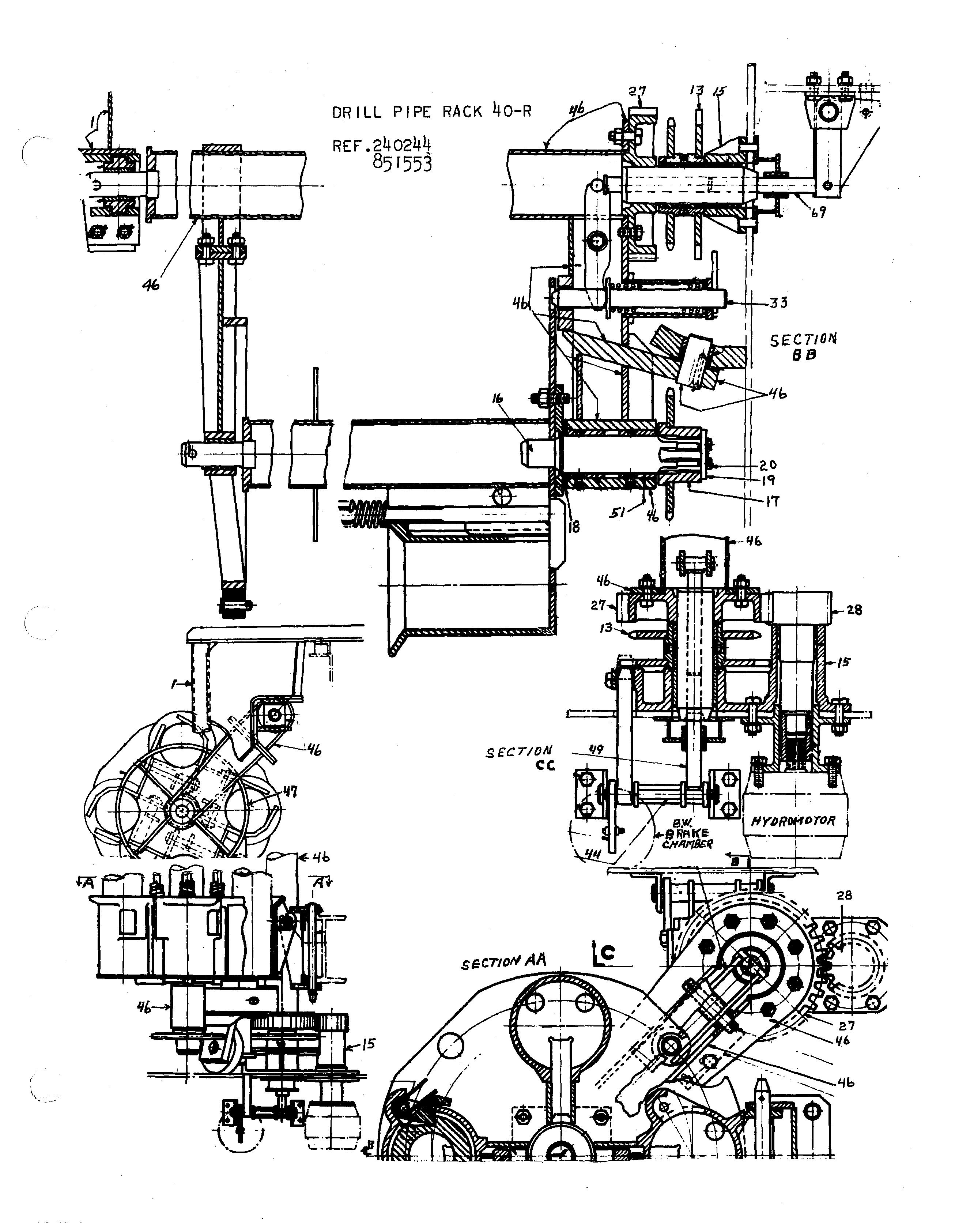
The drill pipe rack must be installed after the derrick is raised. Refer to 240244 and follow the step by step instructions below.
1. Check the match marked teeth on gear "27" and the' drive pinion "28". The marked tooth on the pinion must be meshed between the two marked teeth on the gear when the gears are meshed as the column is lowered into place as described in Step 2.
2. Place lock f.late and sprocket assembly "13" in place on bearing '15", then pick up column "46" using the auxiliary line, and set it in place in bearing "15". Insert bar "6g" from below, pulling pin "44" out far enough to clear the bar, then replace pin "44" in its original position.
3. Bolt the bearing at the upper end of the column to the flanged connection which forms a part of the bearing bracket "1".
4. Lift the pipe rack into place and lower it carefully, entering shaft "16" into bushings "51". Install sprocket "17", retainer plate "lg" and capscrews "20". Make the bolted connection at bearing bracket "47" at the upper end of the pipe rack.
5. Rotate the pipe rack manually until lock latch pin "33" indexes with one of the four holes in the plate which forms the base of the rack. Hold the rack in this position and install the roller chain around sprockets "13" and "17". Check operation of the rack to make sure it is correctly timed to index under the drive head before placing pipe in the rack. If the timing is not right, check the mesh of the gear and pinion as described in Step 1 and also check installation of the to make sure the rack did not move while the chain was being installed.
The rack is powered by a hydraulic motor and controlled for indexing by means of locking latches operated by an a.ir chamber. The ·hydraulic motor which swings the pipe rack is sgt up to limit the swing of the rack to go0 • At the end of the go awing the motor must be reversed for a go0 swing in the opposite direction. Two latches, both controlled by a single air chamber, control the
action of the pipe rack for indexing the correct pipe under the
rotary drive unit.
DRILL PIPE RACK 40-R
REF.240244 Bsrss3

The four sockets in the rack are equipped with spring loaded triggers which connect to vertical reach rods extending up the column. These reach rods terminate in linkages which operate latches at the upper end of the rack. When the weight of the drill pipe is removed from the trigger in the socket the spring forces the reach rod up opening the latch at the upper end thus freeing the pipe from the rack. Each socket also contains spring loaded wrench jaws designed to hold the pipe against rotation when breaking the connection at the rotary drive couplihg.
The two air operated latches referred to previously are interconnected so that when one is engaged the other is disengaged and vice versa. With the latches in one position the pipe rack will rotate 90° while it is swung from its storage position to the limit of its travel under the rotary By reversing the position of the latches the pipe rack will be held station• ary while it swings under the rotary drive unit. A little practice will show how by combining the use of the latches with the hydraulic swing motor it is possible to bring any one of the four pipe sockets into correct position under the rotary drive for removing or adding a length of pipe.
G. GENERAL DRILLING PROCEDURE
Once the drill has been lubricated and checked mechanically, the power cable connected, and the derrick raised and bolted into working position the drill is ready for work. Using the auxiliary reel, hoist two, three or four sections of drill pipe up into position placing the sections in the socl{ets in the drill pipe rack. Then follow the step by 'step instructions below.
1. Screw the bit into the bit collar and set the bit and collar in place in the opening in the drill platform. Hold it in place by clamping it in the tool wrenchv
2. Raise the rotary drive unit to the upper limit of i.ts travel and lock it there by setting the bull reel brake.
3. Using the drill pipe rack hydraulic motor, swing the rack into position so one section of drill pipe is located under the drive coupling. Clean the threads on the pin joint at the upper end of the drill pipe and the threads on the box joint at the drive coupling and coat the threads with thread lubricant. A can of metallic thread lubricant is included with each drill. This is a special lubricant designed for this particular purpose. Do not use ordinary grease as it is not a proper lubr-icant for this application. Thread lubricant is sold by most of the major oil companies. X-1597 Page 9
4. Lower the rotary drive unit onto the first section of pipe and slowly start the rotary drive motor to screw the first section of pipe into the drive coupling. When the joint is made up, raise the drive unit pulling the first section of pipe from the rack. Swing the rack out of the way.
5. Slip the guide bushing over the end of the drill collar. Lower the drive unit and connect the pipe to the drill collar using the same procedure that was used for connecting the pipe to the drive coupling. Use care in making up the joints to avoid damaging the threads.
6. Raise the tools and place the bit wrench in position on th& drill platform and lower the bit in position in the wrench. Start the rotary motor to tighten the bit. When the joint is made up, raise the rotary unit to pull the bit out of the wrench and then store the wrench for future use.
7. Lower the drive unit until the bit rests on the ground and the guide bushing is resting in the guide on the platform. Drop the front and rear doors of the dust enclosure and start the Roto-Clone Motor. Start the rotary machinery, open the main air valve and slowly release the bull reel brake allowing the drill to feed by gravity. As the drilling progresses and the formation becomes h'rder, gravity alone· may not provide sufficient force to insure penetration of the tools. In this case the hydraulic pull down unit may be engaged to promote faster penetration.
8. When the hole has progressed deeply enough so that. the drive unit is approaching the lower limit of its travel and the wrench notches at the upper end of the drill pipe are in line with the air operated wrench jaws under the drilling platform, stop the rotary motion, engage the wrench, close the main air valve and then reverse the rotary motion to unscrew the coupling from the upper end of the pipe. Raise the drive unit to the top or the derrick, swing another drill pipe into position, make up the joint at the drive coupling and raise the pipe from the rack. Swing the rack out of the way, lower the drive unit and couple the new pipe to the one being held in the wrench jaws.
9. When the hole has been completed, let the tools continue to turn as they are withdrawn thus reaming the hole and avoiding the possibility of the tools becoming stuck in the hole. Raise the tools until one section of pipe X-1597 Page 10
is out of the hole, clamp the tools in the air operated wrench, reverse the rotary drive and break the When the pipe is free, raise the drive unit, swing the tool rack into position, set the pipe in the socket, reverse the drive motor to disconnect the pipe from the drive coupling and when the pipe is free swing the rack out of the way. Lower the drive unit and couple up to the pipe being held in the jaws. Raise the tools until the next section of pipe can be removed and proceed as before. When all pipe except the one to which the collar and bit are attached have been placed in the rack, couple up to the last pipe section, raise the drive unit to the limit of its travel and aet the bull reel brake to hold the drive unit and the tools suspended in the derrick. Clamp the lower end of the tool string in the air wrench to hold the tools steady while propelling.
Next open the doors at each. end of the dust by means of the air control valve and lower the machine onto its cats by operating the hydraulic jacks. Checl{ to make sure that the auxiliary and bull reel jaw clutches are disengageds then engage the "Airflex" propel clutches and move.to the next hole.
While moving up it is advisable to stop the Rotc-Clone motor as· it will not be needed while propelling and this gives it a chance to cool and saves some power.
During the actual drilling operation the rotary speed, the amount of down pressure or of feed and the air pressure must all be watched carefully by the driller. speaking excessive rotary speed will shorten bit life and may not result in an increase in feet drilled per hour that is anywhere nearly proportional to the increase in rotative· speed. The amm.int of down pressure applied to the bit either by the pull down unit or by gravity alone will depend on the hardness of the formation being drilled and the rotative speed of the bit. In softer rock' such as decomposed limestone, soft shale or at the top of a hole where the rock is overlain by a layer of earth or clay the rate of feed must be controlled to prevent the bit.from penetrating · faster than the air can remove the cuttings. By watching the air pressure gauge the driller can control the of feed to prevent excessive penetration. If the air pressure gauge shows the pressure to be between 70 and 80 lbs. per square inch the rate of feed is correct. When the gauge reading gets close to 90 lbs. per square inch or exceeds 90 lbs. it is a warning to the driller that the bit is going down toe fast and is apt to plug up. If plugging starts back the bit a foot or two and let the air blow the excess cuttings from the hole, then proceed with the drilling reducing the rate of feed to keep the air gauge reading at about 70 to 80 lbs. The rotatiVe speed should be fairly high in soft formations. About the 5th or 6th notch on the drive motor controller is approximately correct for soft drilling. X-1597 Page 11
• Thank you very much for reading the preview of the manual.
• You can download the complete manual from: www.heydownloads.com by clicking the link below
• Please note: If there is no response to CLICKING the link, please download this PDF first and then click on it.