• Thank you very much for reading the preview of the manual.
• You can download the complete manual from: www.heydownloads.com by clicking the link below
• Please note: If there is no response to CLICKING the link, please download this PDF first and then click on it.


. purpose manual isjto provide information concerning , :the care, maintenande and operation of the : 380W drag line. Every:
beem .to make manual as c.omplete as possible ! :i ja,t th7 tJ.me of Howevef Bucyrus-:ErJ.e Company: . reserves ,:;:-t:.he r.l;ght to .cont1m1;ally improve. J.ts products. For thJ.s
::J7 1 hanges may bE;! are not in this manual.
i Thls. manual is :ki[vided into chapters with appendixes· in Each. chapte!c:.•!is divided in.to sectiori.s:· Pages.are numbered:; each chapter. : For example, page 2-1 J.S the fJ.rst page of ;
2. ' Each has tfble ·of co11;tents at the beginning,. thj chapter. : 1 1
NOrE 1.
i thiFil the wrrds CAUTir, WARNING, and NOTE:
CAUTIONS dover personal injury, death, and machine ,.
I?ay result; from failure to comply with
• the. J.nstructJ.ons. i · :
machine that re-
sul ts from failure to ,comply with the particular
instructicins therein. ·
Notes, Cautions and Warnings serve as critical reminders 1 td alert mining crews of unusual situations and forewarn then of possible hazards on the excavation ;site. Heed these warnings at all times!


I " • 11
SECTIPN 1
I . '!t MAJOR UNITS AND COMPONENTS . . !:i '·
The 380W dragline is designed as an excavating which is powered by a diesel engine or electric motor. The macpine is !ideally sui ted for mining shallow or thin seams of coal! and where 'mining duration is fairly short. The 380W dragline has been designed to use the proven principals larger walking i drag lines an.d at same time incorporates hew modular The modular des1gn allows for ease of dis.assembly and reassembly if the machine is to be moved from one
• loc;:a tion to another.
UNITS
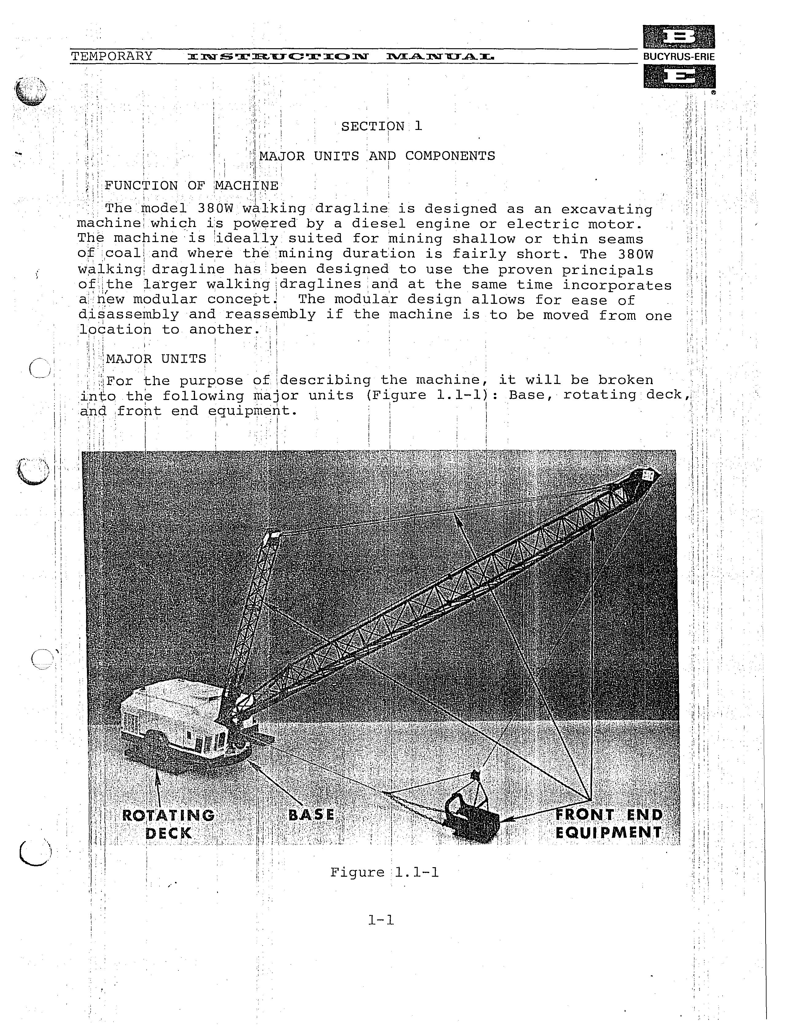
; the purpose ofidescribing the machine, it will be broken
into the following units (Figure : Base, rotating deck,, ci.nd .fropt end 1
The base is the foundation of the machine and consists of a · circular structure which is connected to the rotating deck by a .'center pintle. The base contains a swing rack around which the :machine is driven by the swing machinery and a roller circle I ,assembly. :
rotating • ipcludes the revolving frame, the main 1\ciachiriery, the machinery house, .and the,operator's cab. The · frame of modular units bolted to and
by two mc;tl.n trusses.' Each contains. or supi:Ports, one or more: of the operatlng un1ts of the mach1ne. The ,!ffiachirery house all the:. main machinery, air, lubricai:fion electricallunits of machine. The machinery house ilconsikts of ci. bol te'd ·. framework dove red with clamp-on panels. . !'The operator •s cab, mounts to the: right :front of the revolving : 'I ' and contains'tthe control station. The hoist •: and drag machinery is a modular ,unit which 1 can be removed from . frame !as a complet 1 e unit., \
', ·,The front end equipment consi.sts of the boom, the mast, the 1'fairlead, the' running ropes, boom structural strands, and the \! The···boom is of triangular tubular :construction. It is ii .·manufactured in sections and. bolted together. The boom pins to fli( , the main trusses. The mast 1s of rectangular tubular It isimanufactured in two sections and bolted together. The masti•;l pins to lugs on the ,revolving frame. The boom and mast are sup- I"i ' ported in their working positions by structural strands. The fair-; lead is pinned to on the revolving frame and the truss front!, f ' beam. i ' ' I
CO.r.IPONENTS
BASE '), l ! ; :
. The base consists of three separately welded box sections that l are bolted together. to form .a circular unit (Figure 1.1-2)
:.The two outer secti6ns are aligned to the center section with ·· and the top and bottom with bolts. Welded
!.ii:egral to the center section is a center pintle around which the,: ',::r:evolving frame rot;ates and which also secures the base to the li ;;!;evolving frame. ·The. center pintle is held in the revolving frame' means of a' clampJ 1 collar. Mounted to the upper flange on the router diameter of. base are pads on which hook rollers ride. r. (! · ' :

SWING RACK & LOWER RAILS
to the center base section and concentric with the center pintle is the swing rack (Figure 1.1-3). The swing rack is a large etternal tooth gear which with the lower pinions of the machinery. Mounted in the machined groove on the top inner su,r)face !of the swing rack are the lower rails of the roller circle. ' rails are held with chocks and dlamps.
.iROLLER CIRCLE ASSEMBLY i 'j . !The roller circle:' qssembly consists of 42 tapered and flanged rcillersiwhich ride on 1the lower rails and are held spaced apart lr and outer frames (Figure 1 1.1-3). The tapered rollers ·::; t even distr;i;bution of roller loads both the base and : i; th¢ Furthermore, the action: of the tapered rollers:; orj)the tapered rails''ienables a smooth swing dt the macri,ine with a :t\: mihimumCof roller ski:dding. The rollers are witp poly- ' :l bushings are lubricated througp fittings\ mounted in · ;· the roller pins. The roller circle upper raiis form a complete circle and are secured to the bottom of the fiame with and clamps. \

ROTATING DECK
REVOLVING FRAME & MAIN TRUSSES
The frame consists of four separately welded box sections 1.1-4). The 'first three sections are bolted to and supported by two: main trusses. i The fourth section is bolted to the third se(!tion and supported by hangers pin connected to the main trusses. Each volving frame .section is designed as a module and contains one or :rqre of the operating s of· the machine. ''·:
HOOK ROLLERS
! There are a to.f.al: of six hook' rollers. Twp single hook roller ; t: assemblies are bo+:ted to the swing module at 'the front of the re-

;!-volving frame (Fi 1 q.ure 1.1-5), and two dual hobk roller assemblies 'tare bolted the propel module at the rear (Figure 1.1-6). The 1,
'\:rollers are cpncentric to the center pintle bJ,aring, and engage , ,: I
,: r9ller pa;th/o.n the ·.base The duc;tl hook roller assem-:-
1 • ·engage hook path to the edge of the base
during the walking'mode. During the digging mode all hook rollers, .stabilize the, , · lving frame throughout .the d:i\gging cycle. J
:
\;SWIN? MODULE! :. ,
; i .:IThe first section. of the revolving frame (swing module) conswing units of which the lower gear case is welded integral with:the module structure (Figure 1.1-7). Also welded integral to the module structure are lugs for mounting the mast and fairlead. An optional auxiliary winch can be mounted between the two swing units. The left side of the module holds the auxiliary power generator, the AC power cabinet and the storage batteries used to start the diesel engine. The operator's cab mounts to the right side of the swing module. An extension is mocinted to the front: left side of the module and contains there,sis"tor cabinet. In;,the center of .the bottom plate of the swing · mbaule is the bearing with bushing. Access to the pintle is gai:r'ied through a manhole:cover in.the top surface, of!! the module. to the ,center pintle bearing are the rO'ller circle assembly upper rails. The rails.form a cOmplete c.i'tcle and are chocked and clamped in position. The module is with all 'wiring both air anR- lube, for the on the module.

• Thank you very much for reading the preview of the manual.
• You can download the complete manual from: www.heydownloads.com by clicking the link below
• Please note: If there is no response to CLICKING the link, please download this PDF first and then click on it.