
• Thank you very much for reading the preview of the manual.
• You can download the complete manual from: www.heydownloads.com by clicking the link below
• Please note: If there is no response to CLICKING the link, please download this PDF first and then click on it.

The information is subject to change without notice.
Because of the many variations of';the.,'2810 Drum Miners produced by EIMCO Coal Machinery Incorporated, no drawing will apply to. all miners. Therefore, the drawings - .",',,' ,.. contained in this tYi>idlk . For "-',; specific'i;drawingsand for ordering p:atts,; refer; to' the Parts Manual supplied with the machine.

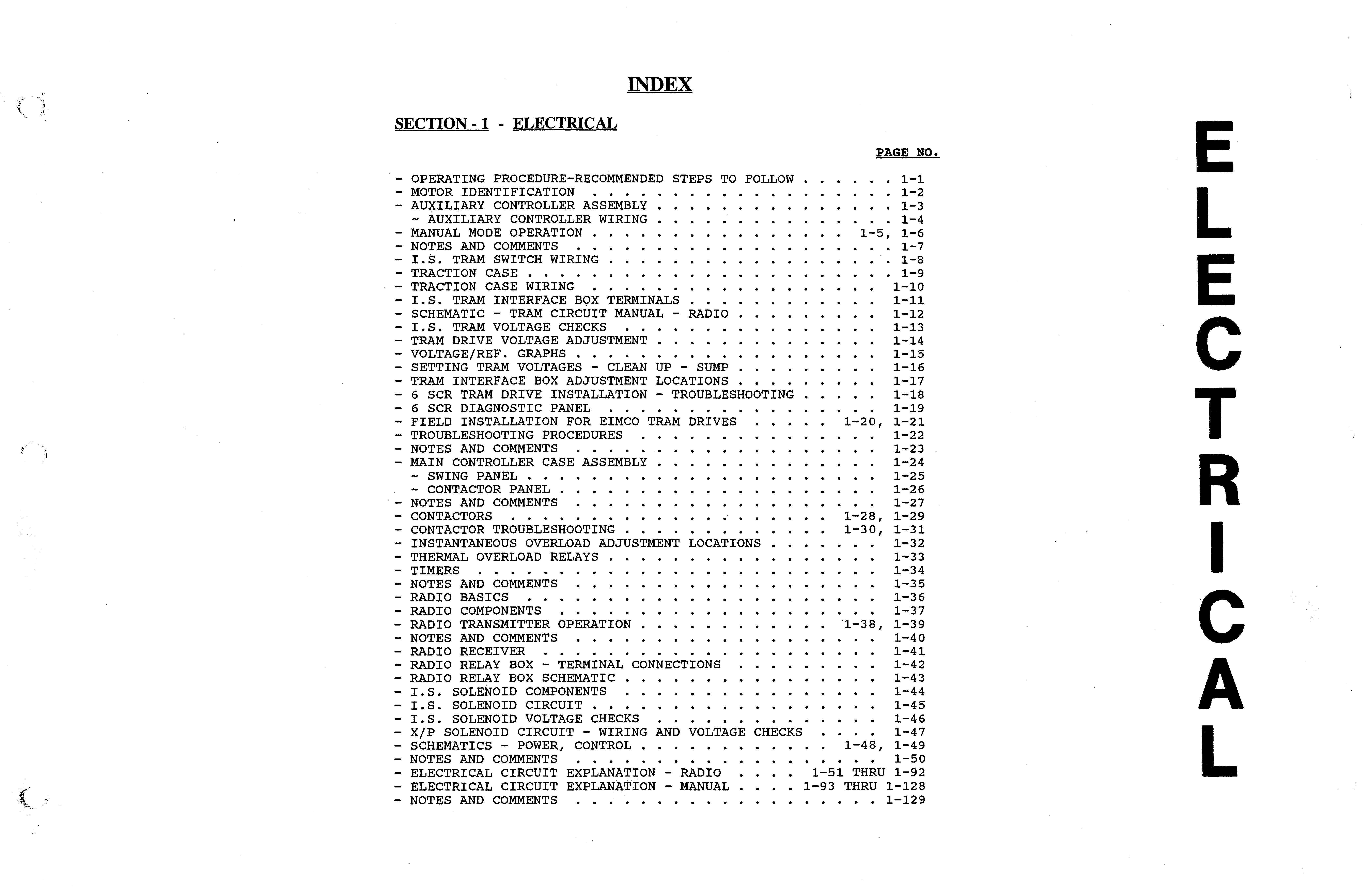
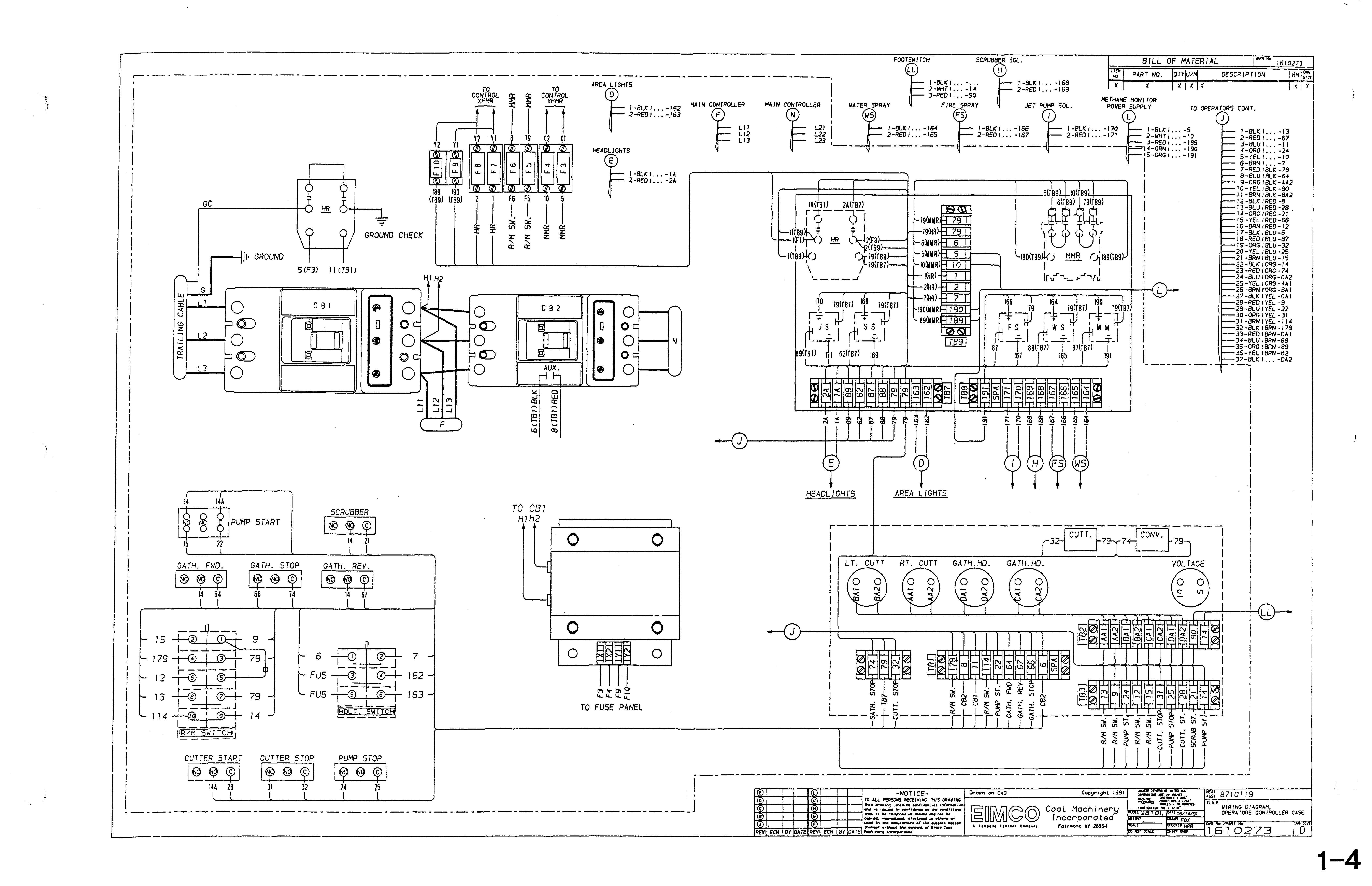
SECTION -1 - ELECTRICAL
RECOMMENDED STEPS TO FOLLOW WHEN OPERATING THE 2810 (Individual Mines May Require Different Cycles of Operation)
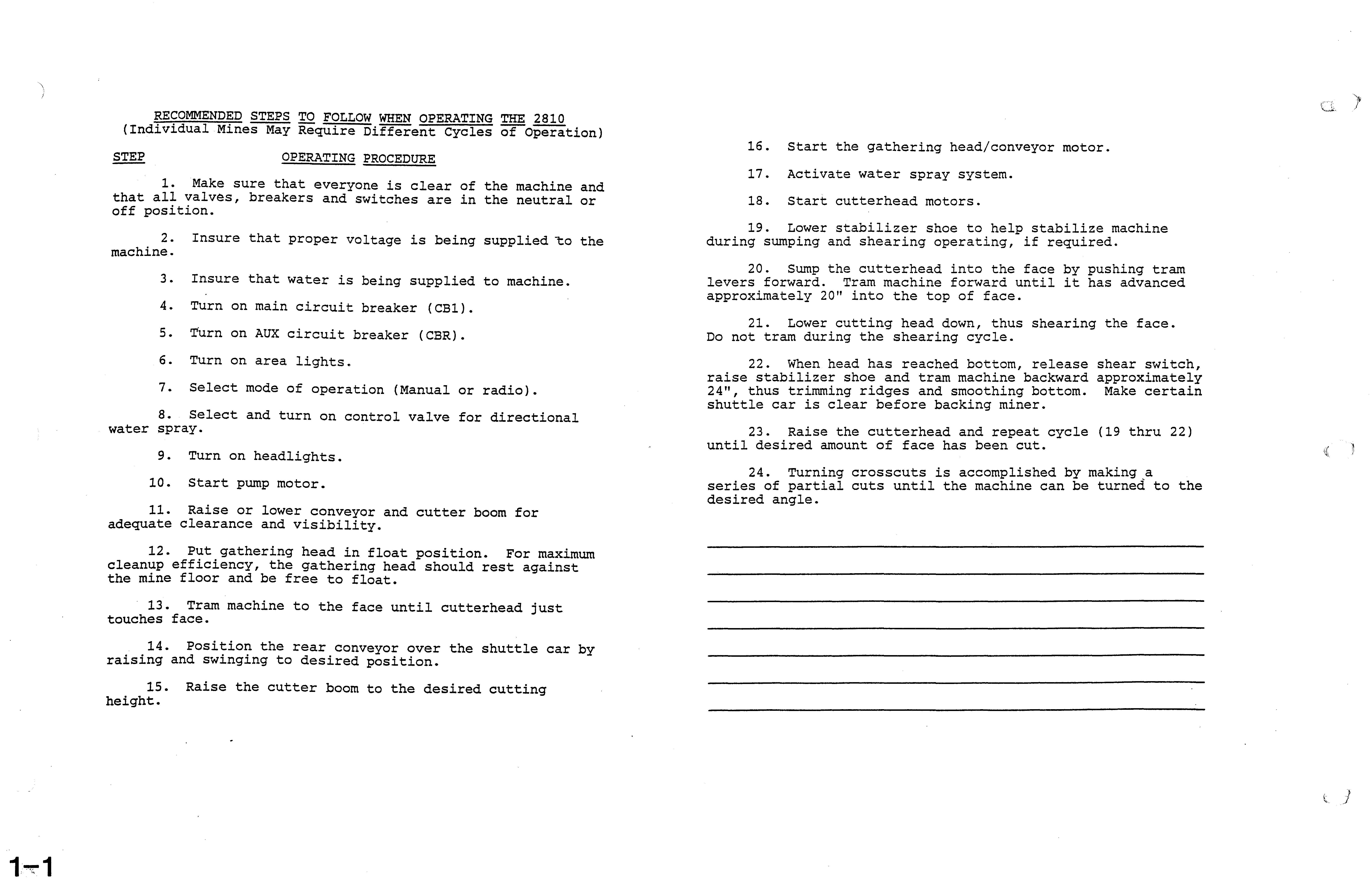
OPERATING PROCEDURE
1. Make sure that everyone is clear of the machine and that all valves, breakers and switches are in the neutral or off position.
2. Insure that proper voltage is being supplied the machine.
3. Insure that water is being supplied to machine.
4. Turn on main circuit breaker (CB1).
s. Turn on AUX circuit breaker (CBR).
6. Turn on area lightse
7. Select mode of operation (Manual or radio).
8. Select and turn on control valve for directional water spray.
9. Turn on headlights.
10. Start pump motor.
11. Raise or lower conveyor and cutter boom for adequate clearance and visibility.
12. Put gathering head in float position. For maximum cleanup efficiency, the gathering head should rest against the mine floor and be free to float.
13. Tram machine to the face until cutterhead just touches face.
14. Position the rear conveyor over the shuttle car by raising and swinging to desired position.
15. Raise the cutter boom to the desired cutting height.
16. Start the gathering head/conveyor motor.
17. Activate water spray system.
18. Start cutterhead motors.
19. Lower stabilizer shoe to help stabilize machine during sumping and shearing operating, if required.
20. Sump the cutterhead into the face by pushing tram levers forward. Tram machine forward until it has advanced approximately 20" into the top of face.
21. Lower cutting head down, thus shearing the face. Do not tram during the shearing cycle.
22. When head has reached bottom, release shear switch, raise stabilizer shoe and tram machine backward approximately 24", thus trimming ridges and smoothing bottom. Make certain shuttle car is clear before backing miner.
23. Raise the cutterhead and repeat cycle (19 thru 22) until desired amount of face has been cut.
24. Turning crosscuts is accomplished by making a series of partial cuts until the machine can be turned to the desired angle.
t--r-----I 40 hp I
L___ .....L_
------J --'----1
I DC TRAM I SO hp I CUTTER HEAD / GATHERING HEAD 1
, '------1 ,. ! 1 - -- --- -- - - - ----..- -- ----- L-_ _ ---a._'--__
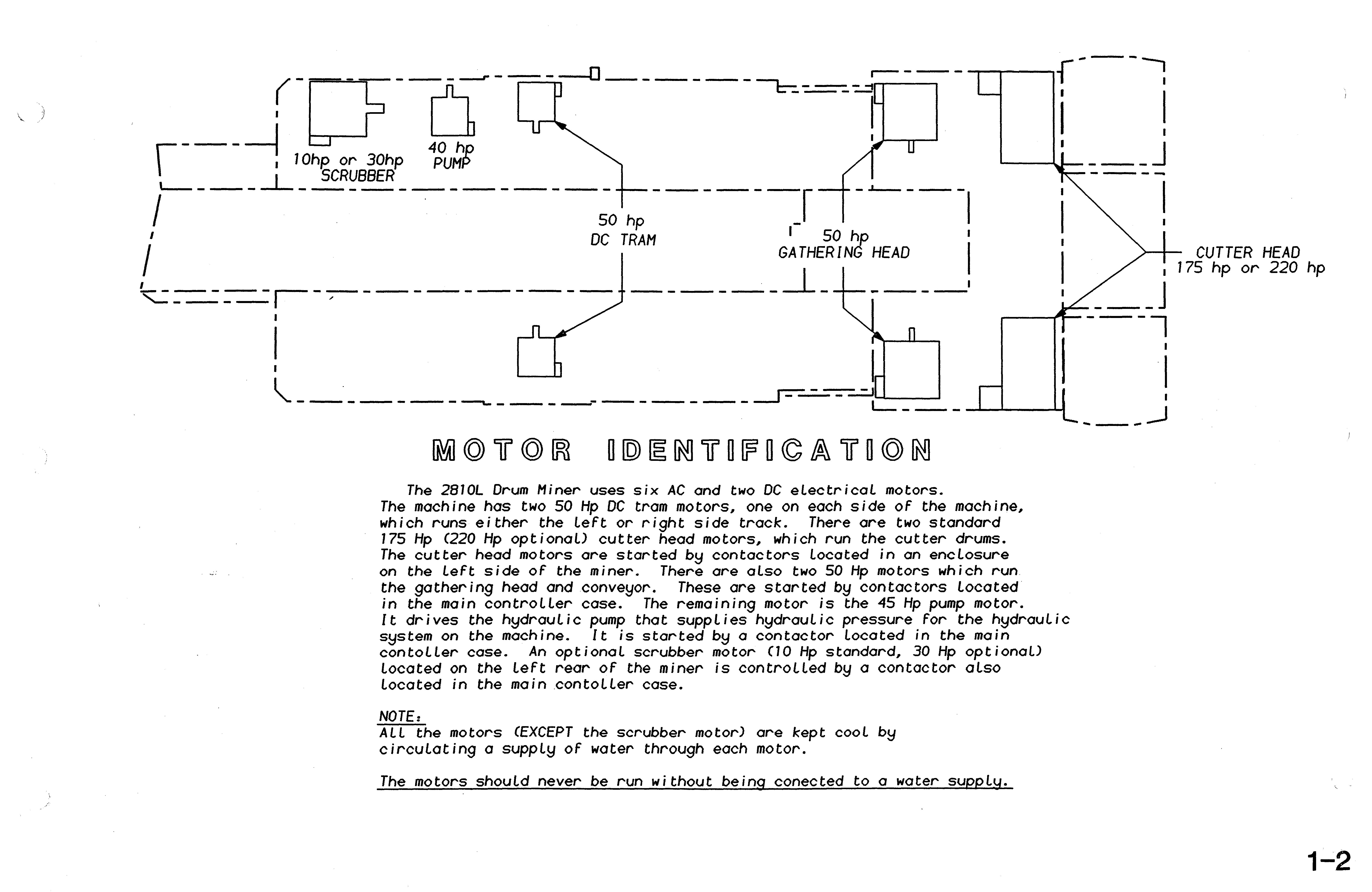
The 2Bl0L Drum Miner uses six AC and two DC electricaL motors. The machine has two 50 Hp DC tram motors, one on each side of the machine, which runs either the leFt or right side track. There ore two standard 175 Hp (220 Hp optional) cutter head motors, which run the cutter drums. The cutter head motors are started contactors located in an enclosure on the LeFt side of the miner. There are aLso two 50 Hp motors which run the gathering head and conveyor. These are started by contactors located in the main controller case. The remaining motor is the 45 Hp pump motor. It drives the hydraulic pump that supplies hydraulic pressure For the hydrauLic system on the machine. It;s started by a contactor located ;n the main contoLler case. An optional scrubber motor (10 Hp standard, 30 Hp optionaL) located on the leFt rear of the miner is controlled by a contactor also located in the main .contoller case.
NOTE:
ALL the motors (EXCEPT the scrubber motor) are kept cooL by circulating a supply of water through each motor.
___ J ---l I I 1-2 BI000234
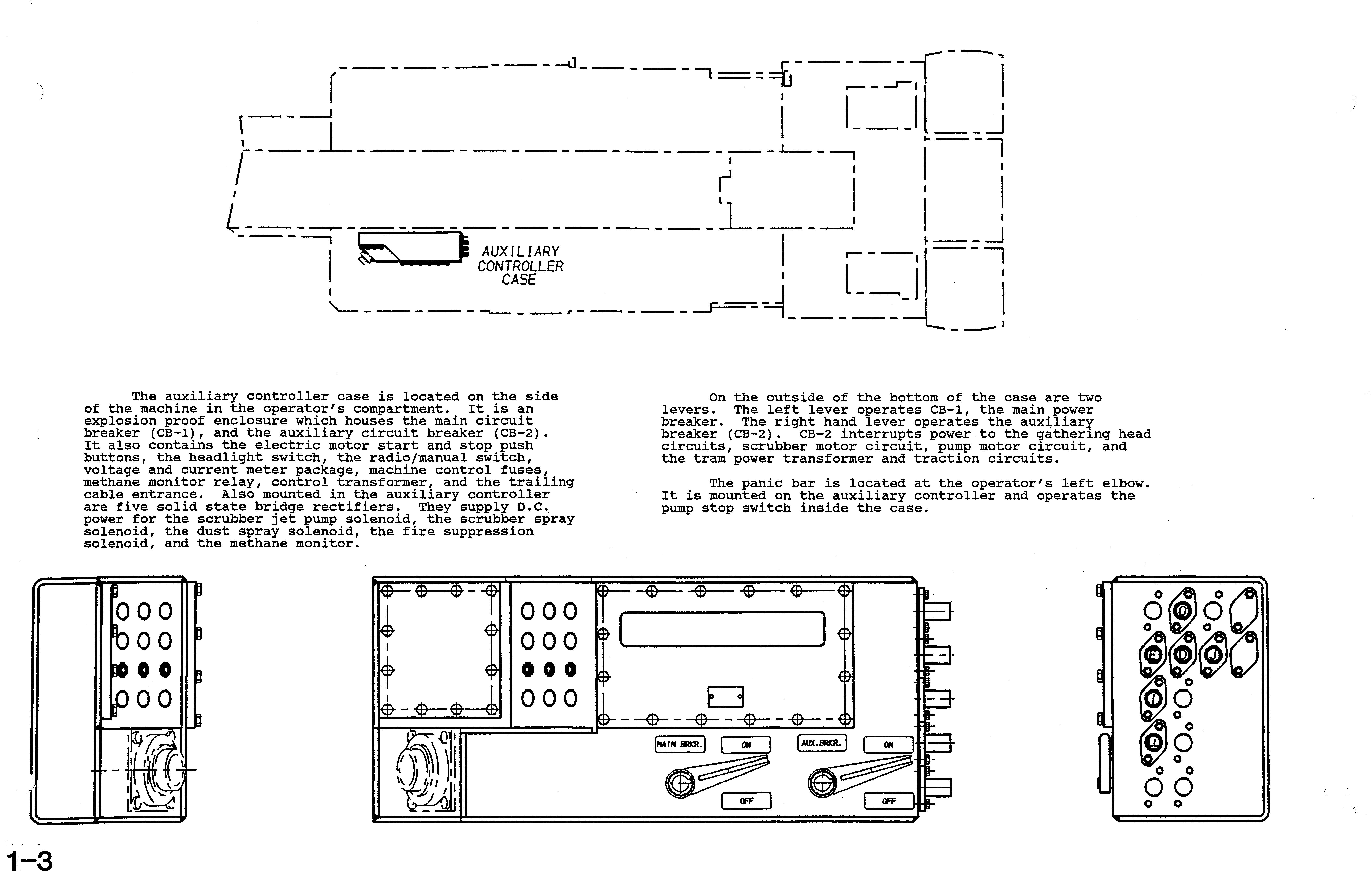
The auxiliary controller case is located on the side of the machine in the operator's compartment. It is an explosion proof enclosure which houses the main circuit breaker (CB-l), and the auxiliary circuit breaker (CB-2). It also contains the electric motor start and stop push buttons, the headlight switch, the radio/manual switch, voltage and current meter package, machine control fuses, methane monitor relay, control transformer, and the trailing cable entrance. Also mounted in the auxiliary controller are five solid state bridge rectifiers. They supply D.C., power for the scrubber jet pump solenoid, the scrubber spray solenoid, the dust spray solenoid, the fire suppression solenoid, and the methane monitor.
On the outside of the bottom of the case are two levers. The left lever operates CB-l, the main power breaker. The right hand lever operates the auxiliar¥ breaker (CB-2). CB-2 interrupts power to the head circuits, scrubber motor circuit, pump motor circuit, and the tram power transformer and traction circuits.
The panic bar is located at the operator's left elbow. It is mounted on the auxiliary controller and operates the pump stop switch inside the case.
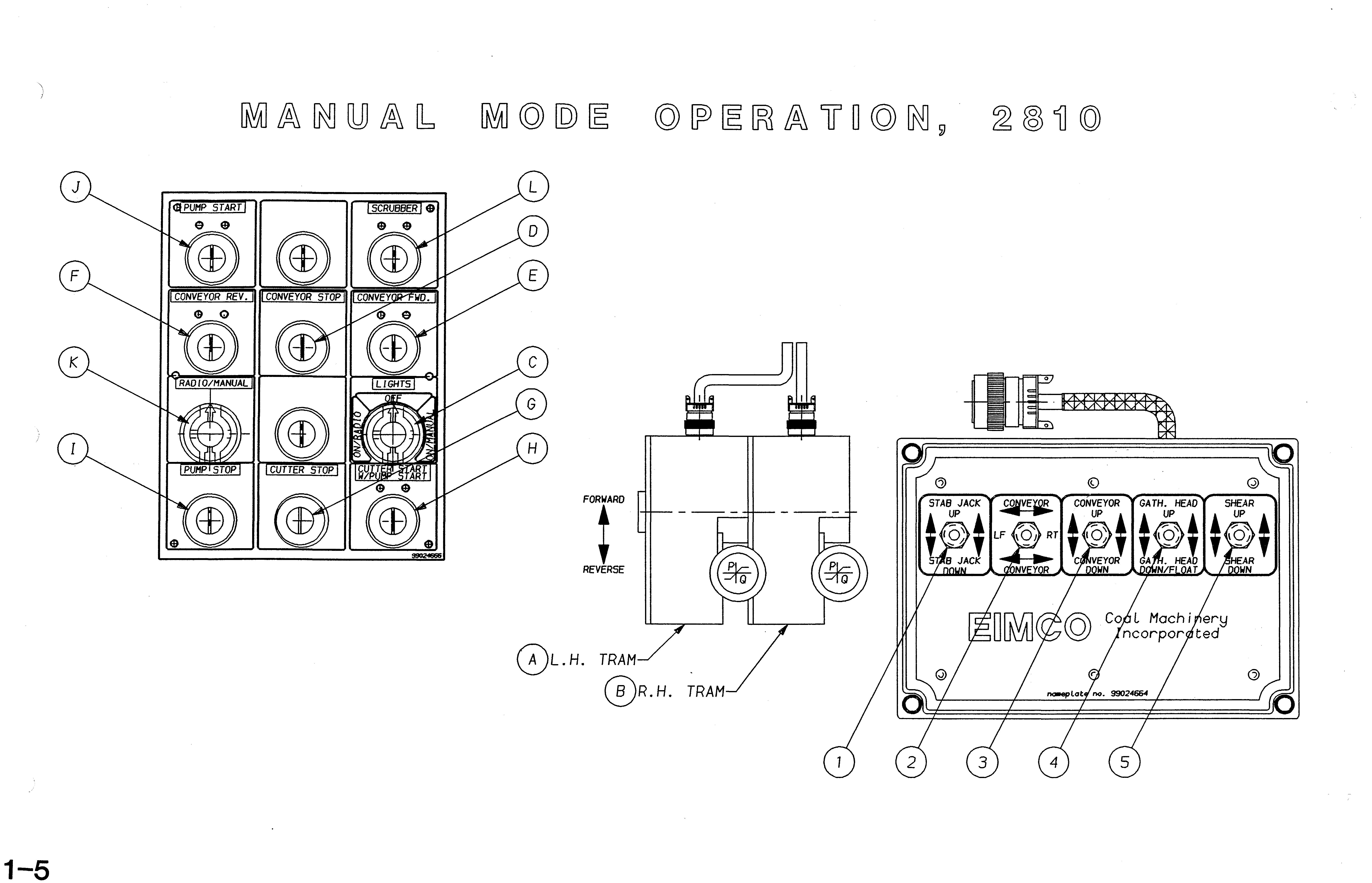
ITEM PURPOSE
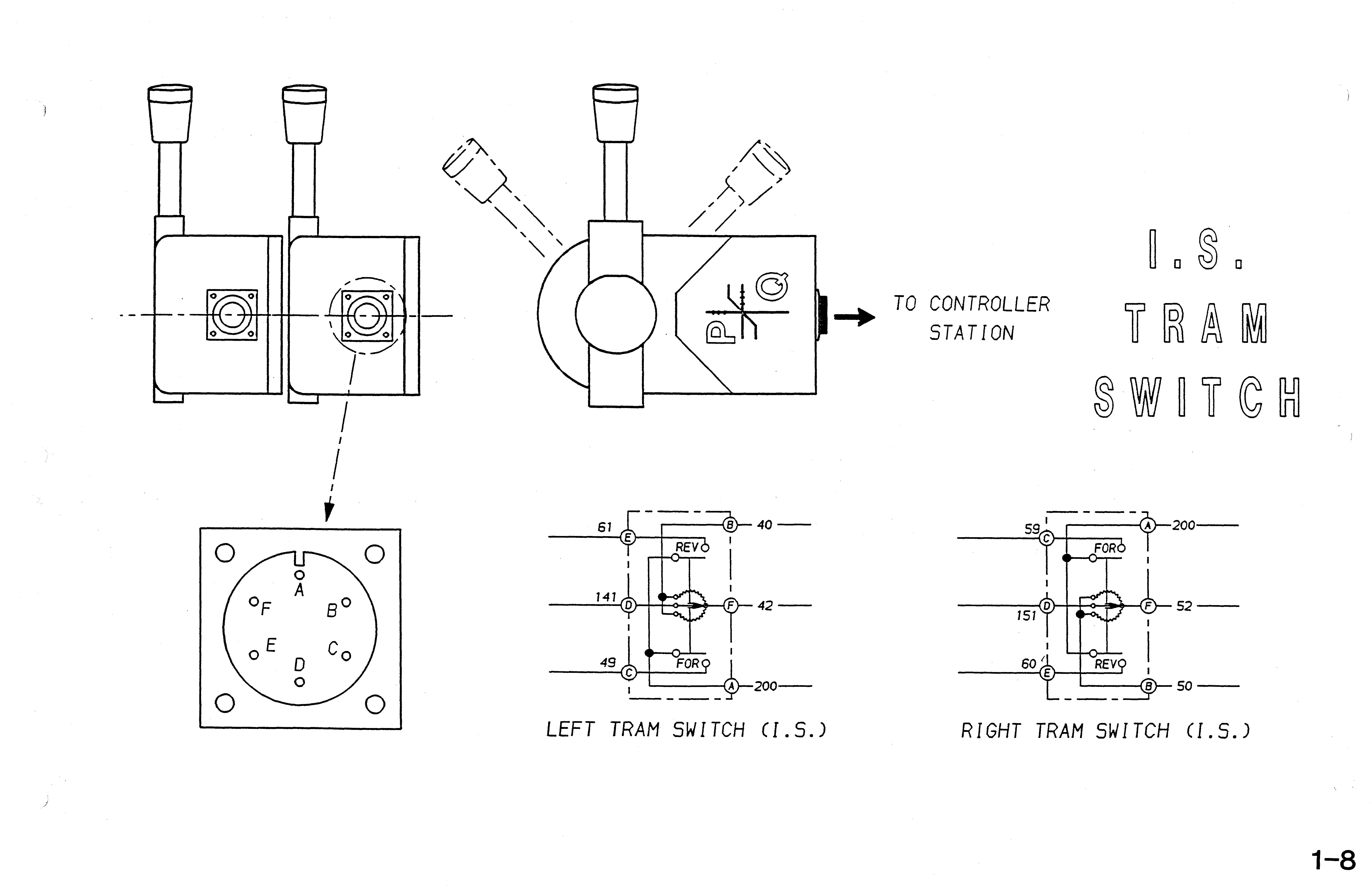
A. Activates left tram motor, thus making left track go forward or backward.
MiffiNS oJ:t' OPERA'.1.'.lUN
Make sure foot operated deadman switch is held down. Push lever up for forward and down for reverse. Lever is spring activated so it will return to neutral when released.
PURPOSE MEANS OF OPERATION
Activates cutterhead motors. Lift lockout flap up on cutterhea start and pump start. Push both buttons in and hold for 2 sec. to activate both motors. When released, switch will spring return to center position.
Activates right tram motor, thus making right track go forward or backward.
Make sure foot operated deadman switch is held down. Push lever up for forHard and down for reverse. Lever is spring activated so it will return to neutral when released.
Shuts machine down in case of emergency.
Activates by panic bar and linkag located to left of operator operator's compartment. Push bar to activate, returns but functions off until starti sequence is reinitiated.
Activates headlights.
Turn knob clockwise to trun headlights on. Counterclockwise to turn headlights off.
Activates pump motor, thus creating hydraulic pressure for hydraulic functions.
Lift lockout flap up and push but ton in to activate, spring return; but motors remain on until deactivated using stop button.
Deactivates gathering head and conveyor motors.
Push button in to deactivate, spring returns but motors remain off until reactivated using start button
Position determines either radio or manual mode of operation.
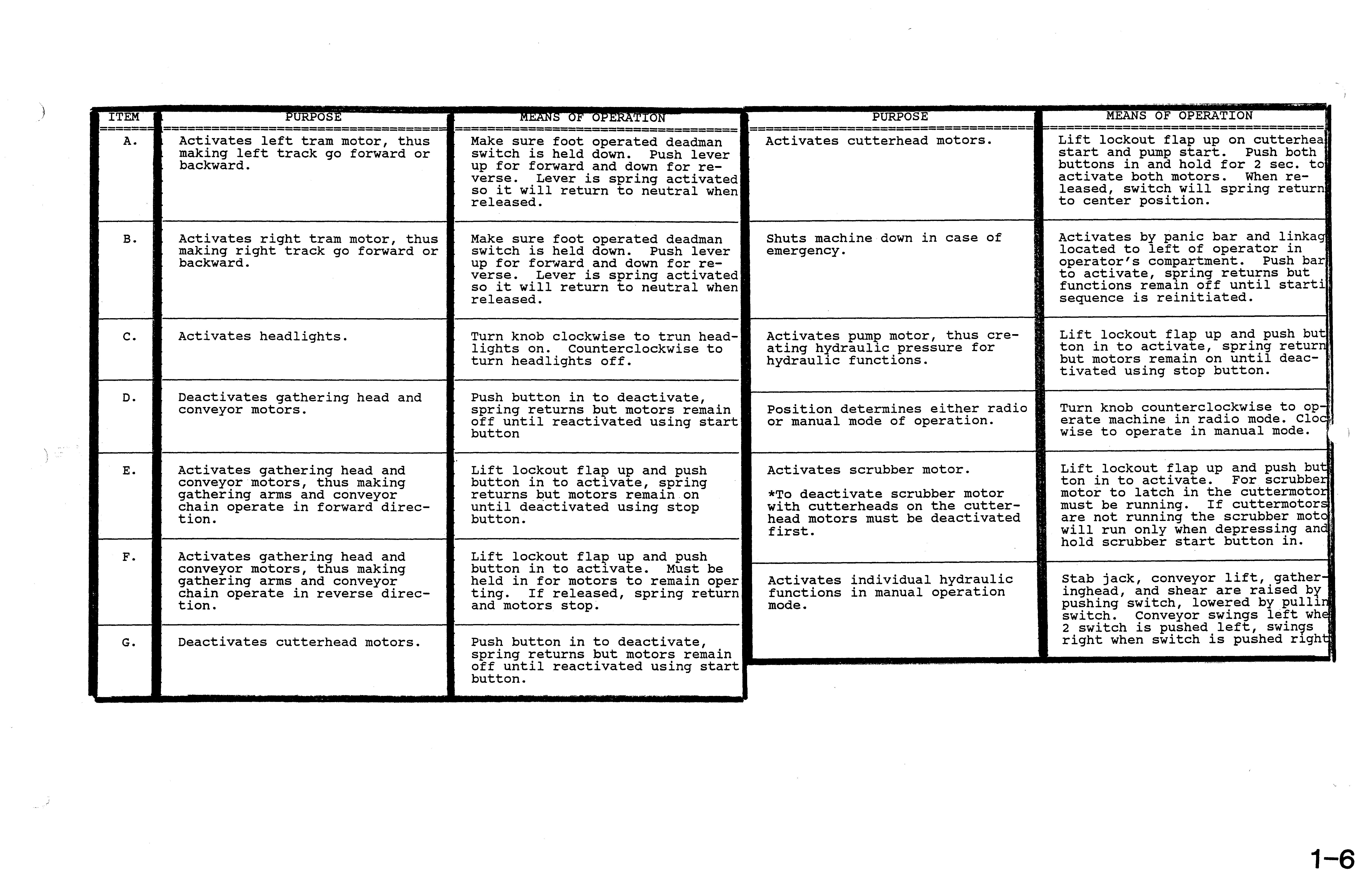
Turn knob counterclockwise to op-.· erate machine in radio mode. Cloe wise to operate in manual mode. .
Activates gathering head and conveyor motors, thus making gathering arms and conveyor chain operate in forward direction.
Activates gathering head and conveyor motors, thus making gathering arms and conveyor chain operate in reverse direction.
Deactivates cutterhead motors.
Lift lockout flap up and push button in to activate, spring returns but motors remain on until deactivated using stop button.
Lift lockout flap up and push button in to activate. Must be held in for motors to remain oper tinge If released, spring return and motors
Push button in to deactivate, spring returns but motors remain off until reactivated using start button.
Activates scrubber motor.
*To deactivate scrubber motor with cutterheads on the cutterhead motors must be deactivated first.
Activates individual hydraulic functions in manual operation mode.
Lift lockout flap up and push but ton in to activate. For scrubbeJ::' motor to latch in the cuttermotoJ:: must be running. If cuttermotorE are not running the scrubber mote will run only when depressing and 4 hold scrubber start button in.
Stab jack, conveyor lift, gatheringhead, and shear are raised b¥ pushing switch, lowered by switch. Conveyor swings left whe 2 switch is pushed left, swin9s right when switch is pushed

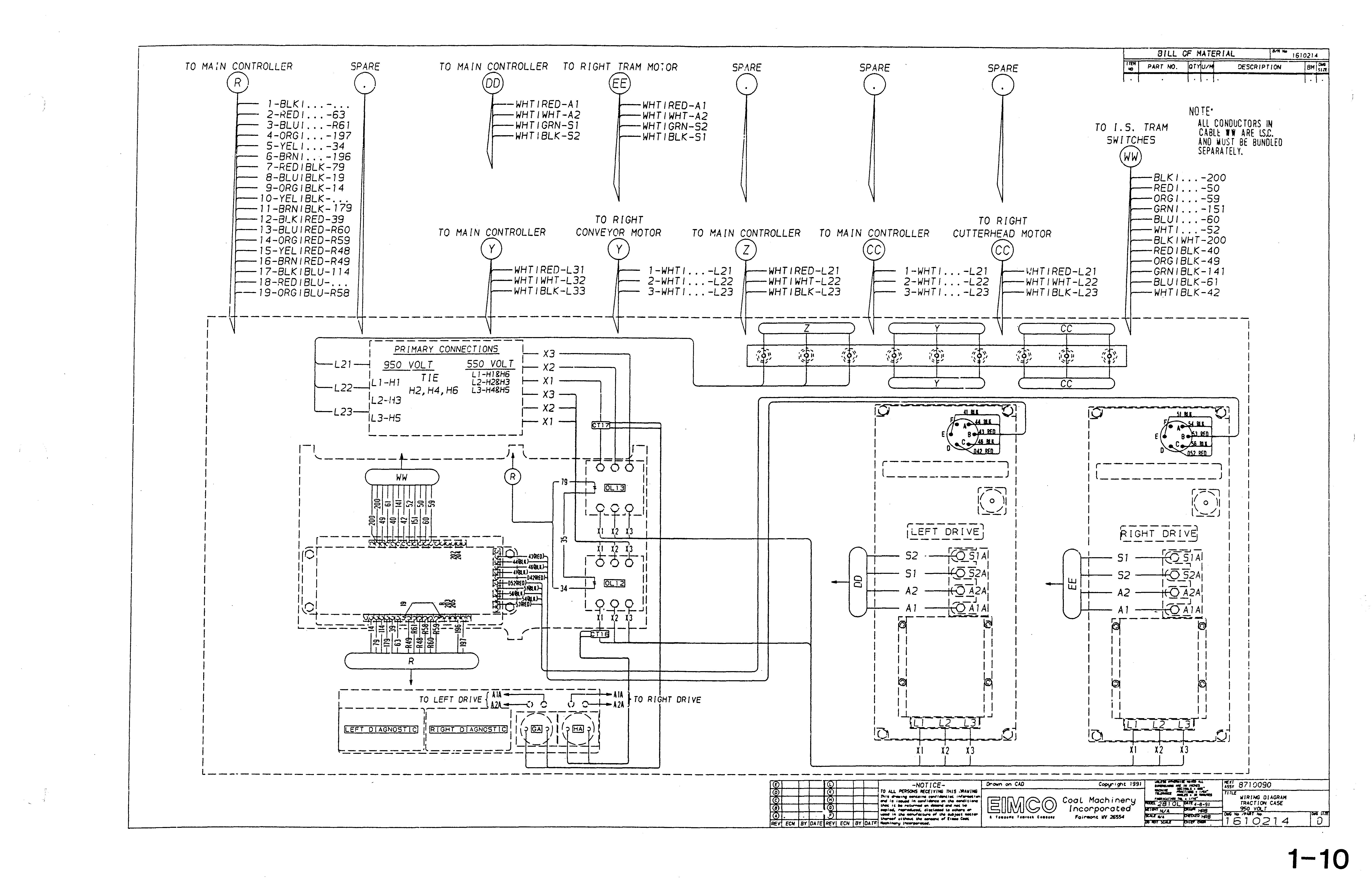
TRACTION CASE
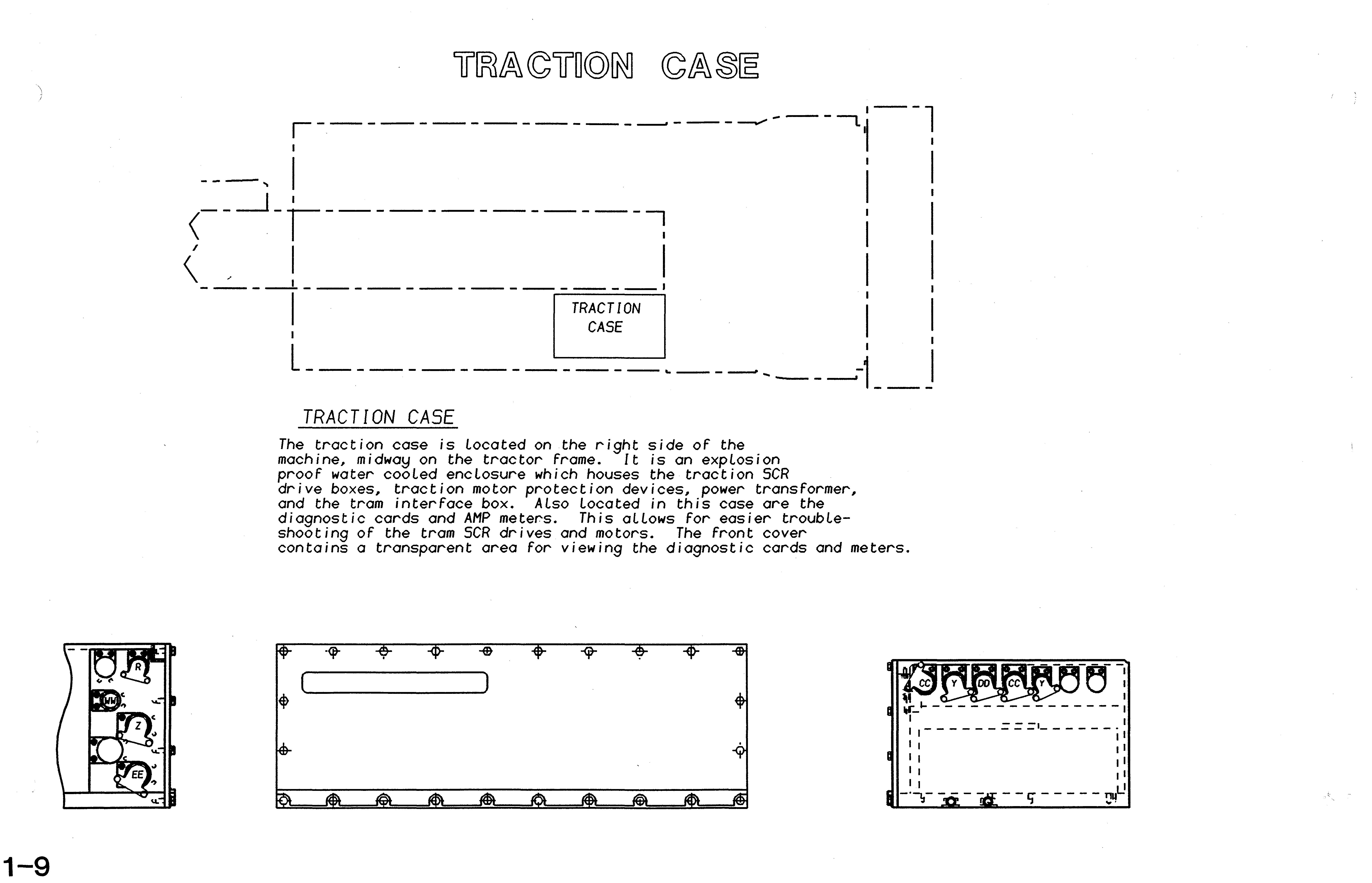
The traction case is located on the right side of the machine, midway on the tractor frame. It is an explosion proof water cooled encLosure which houses the traction SCR
drive boxes, traction motor protection devices, power transformer, and the tram interface box. Also Located in this case are the diagnostic cards and AMP meters. This aLlows For easier troubLeshooting of the tram SCR drives and motors. The front cover contains a transparent area for viewing the diagnostic cards and meters.
I-BLK I . -
2-REDI -63
3-BLUI -R61
4-0RG/ -197
5-YEL I . -34
6-BRNI -196
7-REDIBLK-79
B-BLUIBLK-19
9-0RGIBLK-14
10-YEL IBLK-
II-BRNIBLK-179
12-BCKIRED-39
13-BLUIRED-R60
14-0RGIRED-R59
15-YELIRED-R4B
16-BRNIRED-R49
17-BlK I BLU-114
1 IBlU-
- WHT I RED-A 1
WHT I WHr-A2
WHT I GRN-51
WHT I BlK-52
TO MAIN CONTROLLER Y
--19-0RGIBlU-R5B \ r I PRIMARY CONNECTIONS
r--L21---i 950 VOL T 550 VOLT
WHTIRED-Al
WHTIWHT-A2
WHTIGRN-52
WHTIBLK-51
TO RIGHT CONVEYOR MOTOR TO MAIN CONTROLLER
NOTE' ALL CONDUCTORS IN
• Thank you very much for reading the preview of the manual.
• You can download the complete manual from: www.heydownloads.com by clicking the link below
• Please note: If there is no response to CLICKING the link, please download this PDF first and then click on it.