
Technical Manual
• Thank you very much for reading the preview of the manual.
• You can download the complete manual from: www.heydownloads.com by clicking the link below
• Please note: If there is no response to CLICKING the link, please download this PDF first and then click on it.

INTRODUCTION
1. Read Instruction Manual Carefully.
This manual has been compiled to give the owner and operator information as to the care, operation and maintenance of the machine.
For convenience this manual has been written in sections. Familiarize yourself with the various sections so that you can easily locate the particular information you may need.
Every effort has been made to have this manual as complete as pos sible at the time of printing. However, since the Bucyrus -Erie Company reserves the right to improve its products continually, changes may be made that are not covered in this manual.

II. General Maintenance.
A regular planned inspection of all moving machinery parts should be made at least once each shift.
Structural parts, castings and all non-moving connections should be inspected once a week.
Keep all bolts tight and free from oil or grease.
Keep the machine clean and painted.
Motors, generators and other electrical equipment should be cleaned frequently.
It is best to dig with crawler belts tight on the bottom.
Check grounding of machine frequently. ground should never exceed 25 ohms. Contact resistance of each
Never attempt to inspect the collector rings unless the trail cable is disconnected from the power line. An open switch may not be sufficient protection since there is the possibility that dirt or water in the oil might cause sufficient leakage to result in a dangerously high voltage.
TIl ALwAY2 U2E THE PART2 CATALOG wHEN ORDERING PARTS TO INSURE GETTING THE RIGHT PART FOR YOUR SPECIFIC SERIAL NUMBERED [ViA CH I NE •

HOIST &. MOTOR
FAWICK CLUTCH
ELEVATION VIEW UPPER PROPEL DRIVE
A PLAN VIEW MOTOR DRIVE BI05554

, CHAIN DRIVE
POWER FLOW
SPROCKET
I cVERTICAL SHAFT
PROPEL BRAKE
I. GENERAL OPERATING INSTRUCTIONS

How to operate a power excavator effictently must be learned in much the same way as any skilled trade. No one is a "born" operator. Regardless of previous experience, the new operator must use care to operate the machine safely so as not to endanger men or equipment.
At first glance the large number of levers and switches looks as though operating the machine might be complicated, but most of them control some auxiliary function of the machine such as steering, etc., and are not used in the regular operating cycle. The two levers and the two pedals in front of the operator are the principal controls used in the regular operating cycle and their use will be described in detail further on in these instructions. The first thing the new operator must do is to familiarize himself with the purpose of each of these levers and operating switches.
When learning to operate the machine it is a good plan to study each separate function until fully familiar with the control of all the auxiliary functions of the machine such as propelling, steering, etc., then tryout the main controls which are used in actual digging operations. The main functions can be tried separately until the operator becomes accustomed to the response of the machine to the controls.
When learning to handle the controls be sure there is plenty of clearance and no danger spots around the machine such as overhead wires, culverts, ditches or embankments.
A. INSPECT MACHINE BEFORE STARTING SHIFT
Before beginning to operate the machine at the start of a shift, make a general inspection of the machine to make sure it is ready for operation:
1. Look under the crawlers and around the machinery to see if there is any evidence of lubricating oil leaks. Correct any major leaks and refill to required level. Make a note of minor leaks and correct at first opportunity possible.
2. Look over the eiectrical accessories to.make sure all units are securely mounted and properly adjusted.
3. Lubricate all twice-a-shift (4 hour) and once-a-shift (8 hour) points as covered in the lubrication section of this instruction book.
4. Consult the lubrication record for the machine and service all points which have gone the specified length of time since the last previous servicing.
5. Check operation of all hand levers and foot pedals to see that they work freely without binding, yet with no lost motion.
6. Check main line air pressure which must be at least 110 lb. sq. inch.
7. Engage the clutches to check operation of each motion.
B. POINTS TO WATCH DURING SHIFT
During the shift, watch for any signs of improper operation or adjustment. The following items are of particular importance:
1. Check generator, motors and gears for any unusual noise, loss of power or failure to respond.
2. Check the clutches immediately if they should start to slip excessively during normal operation.
3. Watch the cables to see that they do not become crossed on the drums.
4. When propelling check the tracking of the drive tumblers on the crawler links and; if necessary, readjust the belts to correct improper
5. When operating auxiliary functions such as the steering clutches, etc.) note any tendency of the controls to "hang up" or jam which would indi¢ate improper operation. Correct the adjustment at the earliest possible opportuni ty •
6. watch the air gauge in the operator's cab and investigate immediately should there ·be a sudden drop in air pressure.
C. CHECK MACHINE AT END OF SHIFT
At the end of the shift go over the machine again for evidence of excessive wear or which may have occurred during the shift.
1. Examine all cables carefully for broken strands or other evidence of weak .. ness. Arrange to replace weakened cables before starting another shift;.
2. Clean out carefully any grease or dirt which may have accumulated arou:tld the machinery during the shift. .
3. Clean out excessive mud or .dirt in the crawler belts. This is particularly important in freezing weather. Put planks, brush or dry material under crawlers before shutting down machine if it is likely to freeze. ,
4. If the maehine is to be idle for several hours, move it away from a hi4sh bank where it might be damaged by a slide or falling rocks. Do not leave the. machine in a low spot where there is any. danger of flooding.
5. Let the dipper down to the ground, be sure all brakes are set and place all controls in neutral position. Close the windows at the operator's position and lock all cab doors.
STARTING INSTRUCTIONS
The motor generator set starting equipment usually furnished consists of an . across-the-line oil breaker. Special installations may have push butt?n start and/or a double throw oil circuit breaker and an auto transformer. •
Before initial starting of machine read Section covering Care and Maintenance

Electrical Equipment and the electrical manufacturer's bulletins included in apother book for proper starting procedure of oil circuit breaker and maintenance of equipment.
The direction of rotation of M.G. set should be checked on initial start and anytime thereafter when the cable has been removed from machine, or line trouble has been encountered. It is a good practice to number or letter the plugs and jacks to avoid difficulty.
The air compressor should be started as soon as possible so that sufficient pressure may be built up to operate brakes and clutches.
The emergency reset button should then be depressed, this supplies D.C. current for the operation of the brake and clutch magnet valves and the control field of the rotating control units. It will be necessary to have hoist blower motor operating and oil circuit breaker in before contactor will close.
I. Control of Brakes
All brakes are controlled by means of switches located in the operatoris cab.
Flipping the switch to the "off" position energizes the magnet valve which in turn allows air to enter the brake cylinder and thus releasing the brake. If the magnet valve is de-energized by power failure, by opening the brake sWitch, or if a broken air line causes loss of pressure, the brake shoes are set by spring pressure.
The hoist brake, as are all others, is separately controlled by the snap switch marked "Hoist-Brake" in the panel at the operatoris right. If the loaded dipper is held extended or the hoist line is otherwise under load when shifting from hoist to propel, it is a good plan to set the brake by means of the "Hoist-Brake" snap switch before snapping the "Dig-Propel" switch to the propel position. The swing and crowd brake are controlled by the switches marked "Swing Brake" and "Crowd Brake".
The drag brake, as are all others, is separately controlled by the snap switch marked "Drag-Brake" in the panel at the operatorus right. If the loaded bucket is held suspended or the drag line is otherwise under load when shifting from drag to propel, it is a good plan to set the brake by means of the "Drag-Brake" snap switch before snapp:i,ng the "Dig-Propel" switch to the propel position. The swing and hoist brake are controlled by the switches marked "Swing-Brake and "Hoist-Brake".
II. Control of Clutches
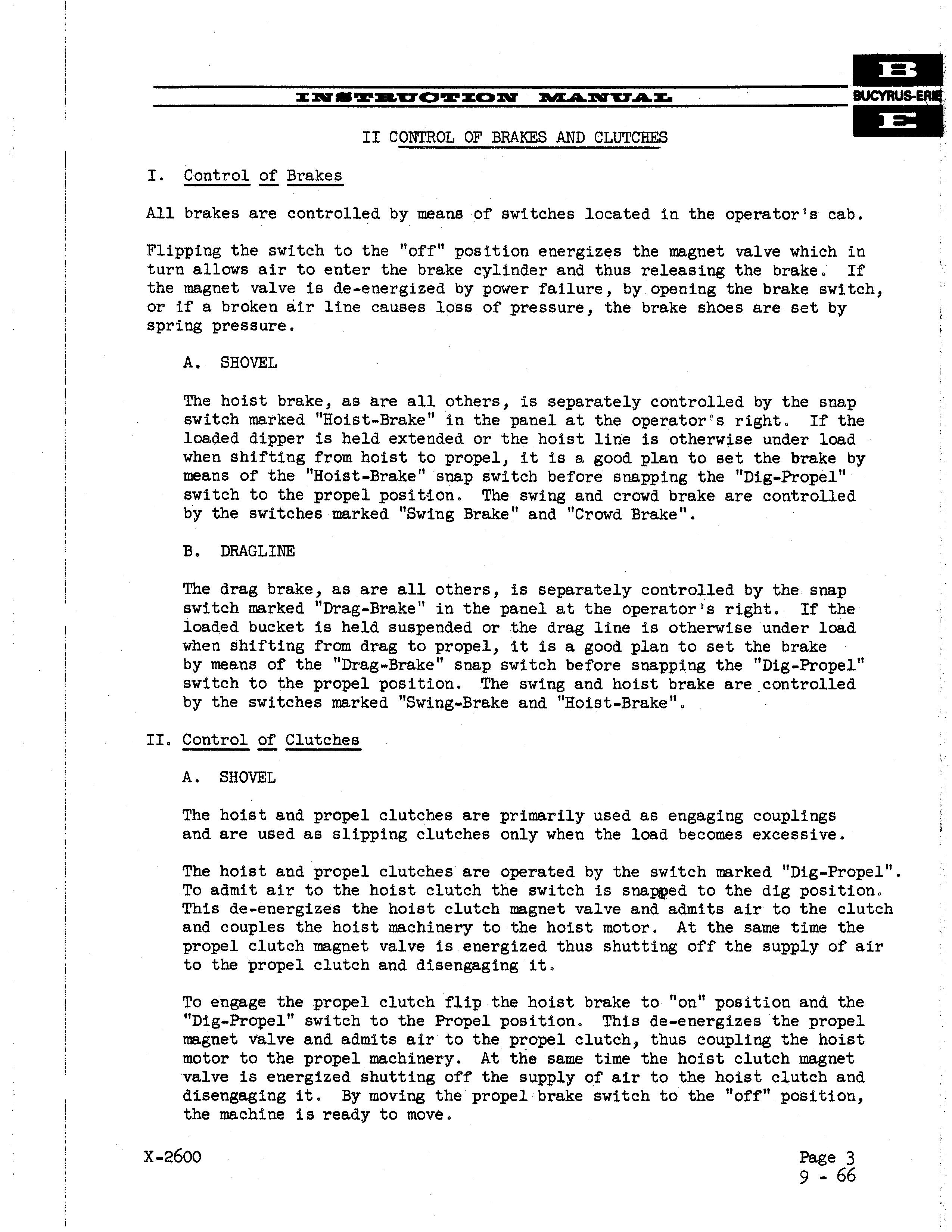
A. SHOVEL
The hoist and propel clutches are primarily used as engaging couplings and are used as slipping clutches only when the load becomes excessive.
The hoist and propel clutches are operated by the switch marked "Dig-Propel". To admit air to the hoist clutch the switch is snapped to the dig position. This de-energizes the hoist clutch magnet valve and admits air to the clutch and couples the hoist machinery to the hoist motor. At the same time the propel clutch magnet valve is energized thus shutting off the supply of air to the propel clutch and disengaging it.
To engage the propel clutch flip the hoist brake to "on" position and the UDig-Propel" switch to the Propel position. This de-energizes the propel magnet valve and admits air to the propel clutch, thus coupling the hoist motor to the propel machinery. At the same time the hoist clutch magnet valve is energized shutting off the supply of air to the hoist clutch and disengaging it. By moving the propel brake switch to the "off" position, the machine is ready to move.
x-2600 Page 3 9-
The crowd clutch is engaged at all times as long as sufficient air is available. The crowd air gauge should be checked daily to see that proper pressure is being obtained. Adjust .pressure at regulator in crowd line in accordance with instructions shown on the instruction mounted near the gauge. The crowd clutch differs from the hoist and propel clutch in that a certain amount of slippage is permitted under,heavy loads thus protecting the machinery from shocks encountered in hard digging.

The Airflex clutches require very little maintenance other than a daily visual inspection to insure proper working .order. Air lines should be checked for leaks, clutch lining inspected for wear, clutch tubes for cracks or weak spots. Lubricants should not be allowed to get on clutch lining as it will cause wea:r and slipping.
The dipper trip cylinder is connected directly to the main pressure line and thus insures maximum pressure for positive operation of the dipper latch.
B. DRAGLlNE
The drag and propel clutches are primarily used 8S engaging couplings and are used as slipping clutches only when the load becomes excessive.
The drag and propel clutches are operated by the switch marked "Dig-Propel". To admit air to the drag clutch switch is snapped to the dig position. This de-energizes the drag clutch magnet valve and admits air to the clutch and couples the drag machinery to the drag motor • At the same time the propel clutch magnet valve is energized thus shutting ·off the supply of air to the prope·l clutch and disengaging'it.
To engage the propel clutch flip the drag brake to "on" position and the "Dig-Propel" switch to the Propel positiQn. This de-energizes the propel magnet valve and admits air to the propel clutch, thus coupling the drag i motor to the propel machinery. At the same time the drag clutch magnet valvJ is energized shutting off the supply of air to the drag clutch and it. By moving the propel brake switch to the "off" position, the machine is' ready to move.
The Airflex clutches require very little maintenance other than a daily visual inspection to insure proper working order. Air lines should be checked for leaks, clutch lining inspected for wear, clutch tubes for cracks or weak spots. Lubricantssl.1ould not be a.llowed to get on clutch lining as it will cause wear and slipping.
QUARRY & MINING MACHINES
110-B, lSO-B, 190-B, '95-8
INSTRUCTIONS FOR CROliD MACHINERY SLIPPING CLUTCHES

The Airflex Clutch is used as a slipping clutch to protect the machinery and crowd ropes from shock loads. In order for the clutch to be effective, the air pressure must be adjusted so that the clutch will slip slightly (1/4 to 1/2 turn) under shock loads, but it should not be allowed to slip to such extent that it gets hot. For normal digging the air pressure is to be between 65 - I 10 lbs., and for tougher digging the pressure must be raised to limit the slipping so that clutch does not overheat. Air gauge pressure should be checked a few times a shift to see that proper pressure is being obtained.
Through field experience it was found that in some cases· the clutch lining has a tendency to seize or adhere to the housing. This could happen when machine is working in tough digging and the clutch warms up due to slippage, and later when easier digging is encountered where no slipping occurs. The seizing could also occur when the machine is not working steady and is shut down for a period of time.
Therefore to make sure that the clutch is in good operating condition, let air out from the clutch through the vented cock which should release the clutch. If clutch fails to release, operate crowd machinery slowly to make sure the clutch lining frees itself from the housing •. After clutch is disengaged the pressure should be raised to proper level so that clutch will slip a little (1/4 to 1/2 turn) under shock loads, but it should not be allowed to slip excessively to such extent that it gets hot.
To insure proper functioning of the slipping clutch for protection of machinery and ropes, it is that the clutch be checked for slippage at least once a week.
The Boom Angle Indicator mounted on the right side of the boom foot is a simple device for indicating the angle the boom makes with the true horizontal. A plate, showing angle in degrees" is bolted to the right side of the boom. A pendulum pointer suspended from one end hangs free. When the boom is parallel with level ground the pendulum would indicate zero degrees. As the boom is raised ,the angle indicated by the pendulum increases.
CONSULT MACHINE SPECIFICATIONS FOR CORRECT OPERATING RADIUS.
For successful operation of machines with dragline type booms it is necessary to operate well wi thin the stability of the machine. The machine specifications, included with these instructions, tabulate permissible bucket size or maximum suspended load (bUCket and contents) for all lengths of booms at various operating radius. The operating radius means the distance of the suspended load from the center of rotation when the machine is on firm level ground.
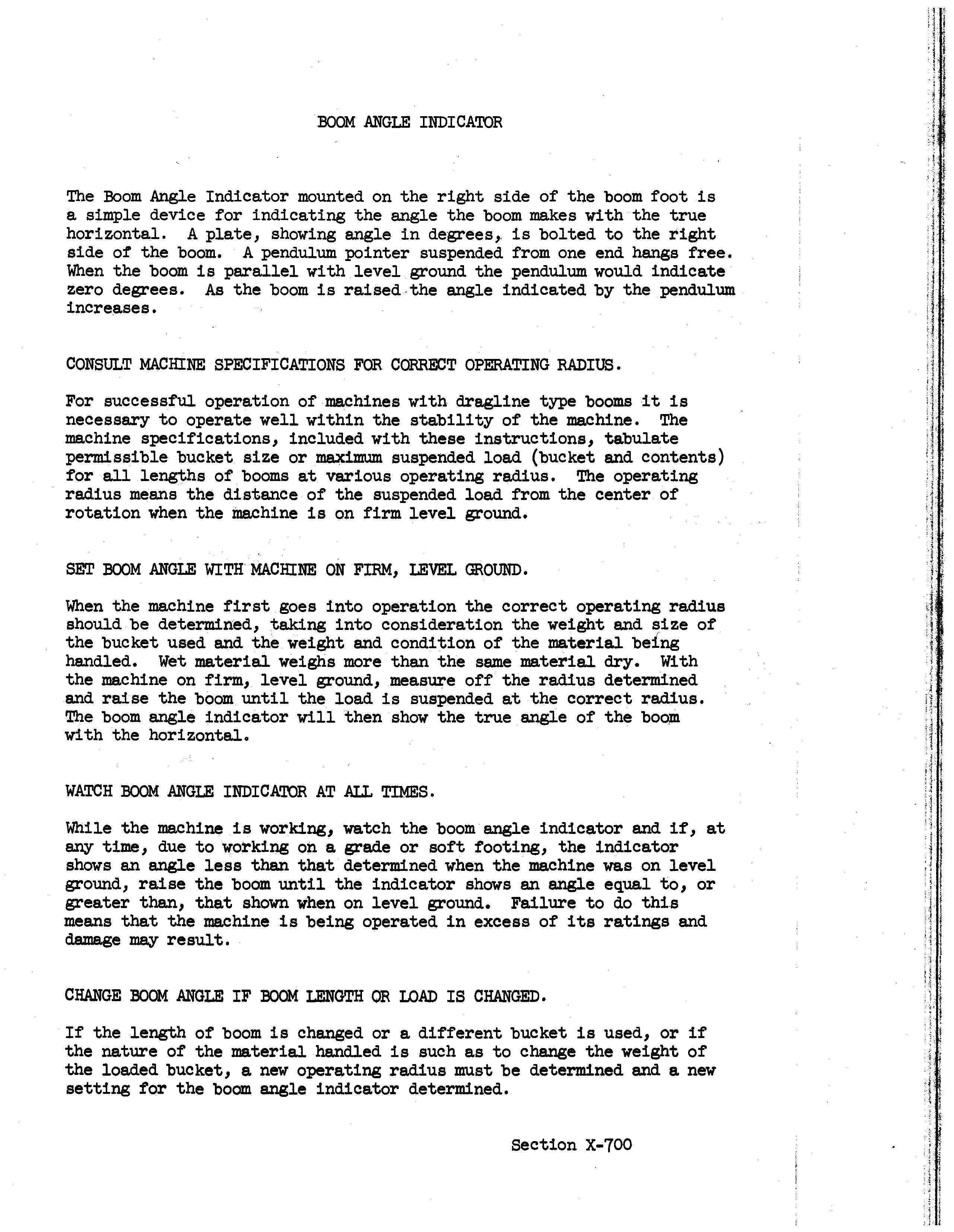
SET BOOM ANGLE WITH MACHINE ON FIRM, LEVEL GROUND.
When the machine first goes into operation the correct operating radius should be determined, taking into consideration the weight and size of the bucket used and the weight and condition of the material being handled. Wet material weighs more than the same material dry. Wi th the machine on firm, level ground, measure off the radius determined and raise the boom until the load is suspended at the correct radius. The boom angle indicator will then show the true angle of the boom with the horizontal.
WATCH BOOM ANGIE INDICATOR AT .AU.. TIMES.
While the machine is working, watch the boom angle indicator and if, at any time, due to working on a grade or soft footing, the indicator shows an angle less than that determined when the machine was on level ground, raise the boom until the indicator shows an angle equal to, or greater than, that shown when on level ground. Failure to do this means that the machine is being operated in excess of its ratings and damage may result.
CHANGE BOOM ANGLE IF BOOM LENGTH OR IOAD IS CHANGED.
If the length of boom is changed or a different bucket is used, or if the nature of the material handled is such as to change the weight of the loaded bucket, a new operating radius must be determined and a new setting for the boom angle indicator determined.
The t.2§..gle spring @ should first be adjusted by means of the T-head bolt @ to a length of "A" in the released position.
The compression spring @ should also be adjusted to 0' C" with the brake set by means of the reach rods and the spring rod.
The brake band is adjusted at the splice with adjusting bolt @ with toggle link in released position, so that when toggle is moved in set position toggle spring is not more than
Brake lining wear is taken up with adjusting bolt @ only.

II-----Truck frame
Lower roller ---t---__..f\
Crawler frame
Take-up tumbler--r- u
("=.,.---- Jack "-"--Front axle
·---Retainer
-------Chock bars
Crawler belt
Crawler Belts
No definite rule can be given as to how tight or loose the tread belts should be as the correct adjustment depends on the type of ground over which the machine is to be moved. In general, the belts should be kept as loose as possible without losing proper tracking of the driving tumblers.
Adjustment of Crawler Belts
Adjustment of the crawler belts is made at the take-up tumbler end of the mounting. The take-up tumblers are bushed on a single forged axle which slides in guides formed in the cat side frames. Chock bars, held in place by a retainer, hold the axle with the desired tension on the belts.
To adjust the crawler belts, first remove the chock bar retainer from each side bolted on the take-up axle. Then place the hydraulic jack furnished with the machine in position on one side between the truck frame and the take-up axle as shown on the drawing. Be sure jack handle points up. Pump the jack until the cat belt is just tight enough to insure proper tracking of the driving tumbler. Insert the necessary thickness of chock bars, back off the hydraulic jack and replace chock bar retainer. Repeat this procedure on the other side; be sure to insert the same thickness of chock bars.
After the crawler belts have been properly adjusted, store the hydraulic jack where it will be readily available the next time it is needed.

• Thank you very much for reading the preview of the manual.
• You can download the complete manual from: www.heydownloads.com by clicking the link below
• Please note: If there is no response to CLICKING the link, please download this PDF first and then click on it.