Technical Manual
• Thank you very much for reading the preview of the manual.
• You can download the complete manual from: www.heydownloads.com by clicking the link below
• Please note: If there is no response to CLICKING the link, please download this PDF first and then click on it.

The purpose of this manual is to provide information concerning the mechanical maintenance of the 1370W Walking Dragline.

The Model 1370W consists of three major units, the lower works, the rotating deck and the front end equipment. The lower works provides a foundation for the revolving frame and contains the base, swing rack and roller circle. The rotating deck includes the revol ving frame and machinery house. The machinery house encloses all of the hoist, swing, drag and propel machinery, and the electrical systems required to control machine functions. It also contains an air filtration system to minimize heat and dirt build-up in the machinery house. An elevated cab mounted on the house provides the machinery operator's station. The cab contains all machine operating controls. The front end equipment is comprised of the A-frame, fairlead, mast, boom, running ropes, boom structural strands, and dragline bucket.
This manual consists offour chapters, each divided into sections. A table of contents is located in the front of the manual.
Throughout this manual the words CAUTION, WARNING and NOTE appear in bold face type. CAUTION is preceded by the safety alert symbol .A, and indicates that injury to personnel could occur if the proper procedures are not followed during operation or maintenance. Always read the CAUTION note carefully and use extreme care while performing that particular function.
WARNING indicates a possible hazard to the machine orits components ifthe proper procedures are not followed. Whenever the word WARNING appears, special attention should be given to prevent possible equipment damage.
NOTE is used to stress a point or to give additional information concerning the procedure being discussed.
These CAUTION's and WARNING's are not all-inclusive. It is impossible for Bucyrus-Erie Company to know, evaluate, and advise maintenance and service personnel in every conceivable way a service operation might be performed and of the resulting possible hazardous consequences of each method. It is therefore extremely important that anyone who uses a service procedure or tool which is not recommended by Bucyrus-Erie Company to first satisfy himself that the service procedure or tool he chooses will not jeopardize his own safety, the safety of others, or cause machine or component damage.
 ROTA TIN G DEC K

CHAPTER 2- AIR SYSTEM

SECTION 1- MAINTENANCE PROCEDURE
GENERAL
This section of the manual describes those aspects of maintenance such as schedules, reports, and safety as related to the Model 1370W Walking Dragline.
MAINTENANCE SCHEDULES AND REPORTS
Ideally, all maintenance should be approached from the preventive standpoint and on a regularly scheduled basis. Obviously, this approach keeps downtime to a minimum and results in reduced maintenance costs. To establish a preventive upkeep program, scheduled inspections and an operator's daily report are the most useful tools available. Scheduled inspections should be conducted by the Mine Mechanical and Electrical Maintenance Departments since they are the most qualified. Either department should generate a certain amount of paperwork, such as inspection records, that become a part ofthe mine's permanent file on the machine. The inspection records should be explicit, complete, and cover every part of the machine. Each machine operator should complete a daily record ofthe machine's performance. This record should include time worked, time down, reasons for all delays, and observations on any unusual conditions encountered during operation. From these records, items that can potentially cause machine downtime can be corrected or prevented immediately, or scheduled for a future date when the machine availability can be coordinated with the other mine activities.
Each problem should be thoroughly reviewed and evaluated before scheduling any maintenance or repair. The following points should be considered during the evaluation.
1. Is the problem one of normal wear?
2. Is the problem caused by machine application?
3. Is the problem a result of operator error?
4. Is the problem a result of unavoidable circumstances?
5. Is the problem of a repetitive nature?
6. By leaving repairs to a later date, will any other component be affected?
7. Can repairs be accomplished immediately?
8. Will the cost of repairs immediately, rather than later, be worthwhile?
9. How long will the machine be down?
Once maintenance or repair has been scheduled, take following points into consideration to minimize downtime and expense.
1. Are all tools and equipment needed to accomplish maintenance or repair available on the job, and are they in good repair?
2. Are all replacement parts on hand and readily available?
3. Is replacement of auxiliary parts, such as seals and bearings, necessary to accomplish repair, and have they been ordered?
4. Is all disassembly and reassembly data available?
5. Have repair crews been scheduled?
6. Will there be adequa te supervision on hand for the repair crews?
7. Has the manufacturer been consulted for Service or Engineering assistance?
8. How long will the machine be down?
Once repair has been accomplished, the problem should again be reviewed with the following things in mind.
1. Was the cause of the problem permanently corrected or just patched?
2. What guarantee is there the same problem will not occur again?
3. Is consultation with the manufacturer for design improvement necessary?
4. What costs were incurred in downtime, parts, tools and labor?
5. Could the problem have been prevented by prior action?
SAFETY GENERAL
The importance of overall safety in the maintenance of a dragline should always be emphasized; excavating operations may involve a varie;;y of hazardous conditions. Many critical dra/;;line components are subject to wear and other deterioration which limits their useful life; thus they are expendable. When new, all such parts have a builtin reserve strength against unknown factors and reasonable loss of durability from gradual wear. If, however, inspection and adjustment are neglected, these parts eventually reach a condition where they become a safety problem. Similarly, failure to replace various mechanisms to insure proper performance of the dragline also constitutes a safety problem. Study this manual carefully and follow all recommended procedures to avoid unsafe conditions. Review the manual periodically to refresh your knowledge ofthese procedures. Supervisors, operators and maintenance men should continuously follow safe practices.
IN-OPERATION MAINTENANCE
Safety requirements dictate that all draglines in acti ve service be inspected at regular intervals for proper adjustment of operating mechanisms, excessive wear of components, system cleanliness andany other defects. In-operation deficiences should be carefully investigated. It should be determined if a safety problem exists. Remember, maintenance is vital to safe operation. It should be performed systematically by competent personnel.
From an economic standpoint, it is advisable to perform as much of the upkeep as can be safely accomplished while the dragline is running Obviously, there are some maintenance such as gear tooth inspection and replacement, which require machine shutdown. However, many support duties can be safely and handled at shift change when the dragline is still activated.
Automatic lubrication systems function throughout the operational cycles of the machine. These systems release premeasured lubricant which lengthen the wear life of the machinery units. Other parts of the machine may be manually lubricated in a safe manner through extended grease or oil fittings designed to keep the operator's hands at a safe distance. Where this is not possible, the machine must be shut down during the required lubrication.
A repair or maintenance job on dragline equipment is not complete until guards, plates and other safety devices have been replaced before the equipment is restored to operation.
PRECAUTIOI\IS BEFORE AND DURING MAINTENANCE WORK
The operator must be sure the dragline equipment is in a safe position before repairs or adjustments are made. The machine should not be endangered by falling rock or a yielding support surface. Before beginning repair or adjustment, the operator shall:
• Set the bucket on the ground.
• Set all brakes.
• De-energize control functions.

• Do whatever else is necessary to prevent accidental movement of the machine.
NOTE: Ifpower is essential to the repair, it should only be energized when all personnel are clear of electrical and mechanical hazards. The power should only be energized during the required period and not when repair work is being done.
Prior to undertaking any work, maintenance personnel should notify the operator about the nature and location of the job. If work is to be done on or near moving parts, the starting con troIs should be locked in the "off' position and tagged. The lock and tag should be removed only by the maintenance people who installed them or other authorized personnel. During all phases ofmaintenance, use extreme caution when working near electrical equipment. Never work near exposed, energized high voltage connections.
Approved protective equipment such as gloves and insulated hooks or tongs should always be used when high voltage electrical cables are handled. Only qualified electricians are permitted to directly maintain electrical equipment such as motors, transformers, and switches.
--
h CAUTION: Many of the component parts of the 1370W are heavy, bulky items. Extreme caution should be used when lifting these items. Personnel should be certain of the weights of components before attempting to lift them, either manually or with some lifting device. All applicable safety rules should be followed when using cranes or other lifting equipment. Be sure of the load, lifting height and radius, and capacity of the machine before lifting a load. Failure to follow all applicable safety rules when lifting heavy parts can cause serious or fatal injury.
CHAPTER 1
SECTION 2- LOWER WORKS
The lower works (figure 1) of the 1370W drag line should be checked periodically for wear and damage. The base structure should be checked monthly for cracking or buckling, especially in the areas of the center pintle and the roller circle diaphragms. The roller circle rails and rollers should be checked weekly for proper lubrication, pitting, spalling, and galling of the wear surfaces. The rail clamp bolts and chocks should be checked for tightness. The swing rack should be checked weekly for proper lubrication, cracked or broken teeth and pitting, spalling or galling of the teeth. The swing pinions should also be inspected at this time paying close attention to the condition of the pinion
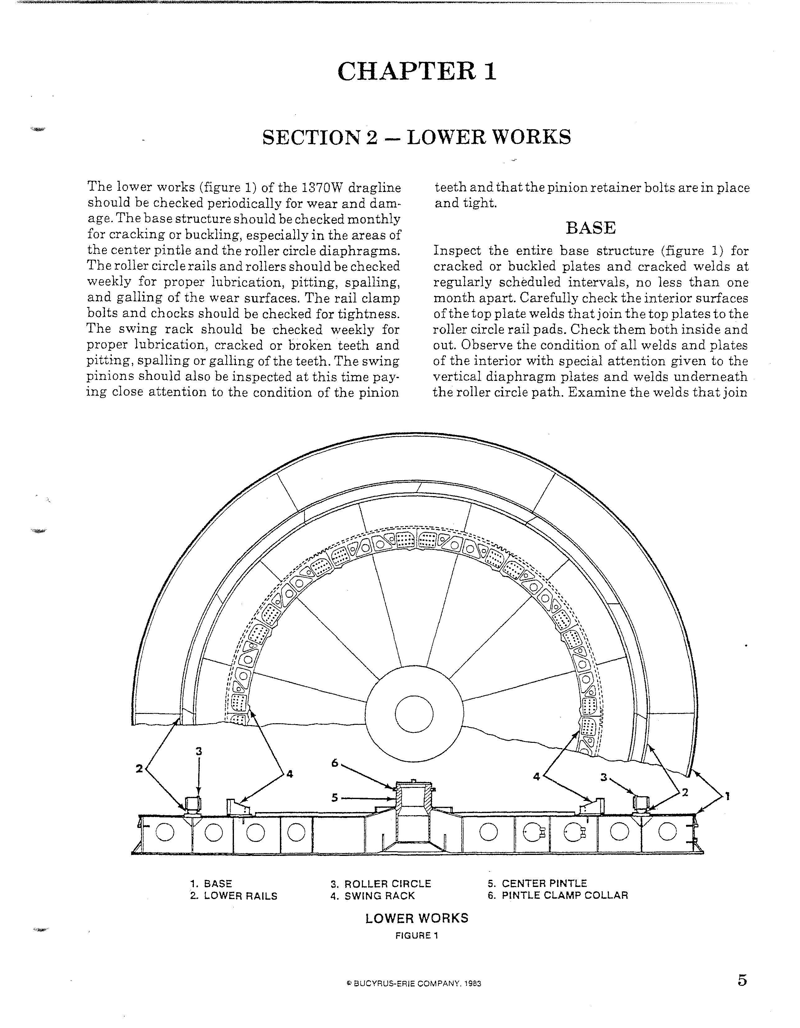
teeth and that the pinion retainer bolts are in place and tight.
BASE
Inspect the entire base structure (figure 1) for cracked or buckled plates and cracked welds at regularly scheduled intervals, no less than one month apart. Carefully check the interior surfaces of the top plate welds that join the top plates to the roller circle rail pads. Check them both inside and out. Observe the condition of all welds and plates of the interior with special attention given to the vertical diaphragm plates and welds underneath the roller circle path. Examine the welds that join
1. BASEthe center pintle section to the intermediate sections. Check all bottom plates for buckling and indentations to make sure no localized high ground loading is occurring. Watch all vertical diaphragms, both radial and circumferential, for paint cracking or checking in lines. This condition indicates high stress pattern development.
REPAIR
The basic repair procedure for the base is repair welding of cracked or damaged welds or plates. Use welding procedures as outlined in appendix. When repairing cracks do not add reinforcing plates unless so advised by Bucyrus-Erie Service Departmen t.
SWING RACK
Inspect the swing rack and pinion weekly to insure there are no bare metal spots or contact points, broken tooth ends, loose bolts or broken welds at back of rack. In particular, check for pitting, abrasion, scratching, spalling, and galling as shown in appendix under the topic, GEAR INSPECTION. All teeth should carry a good coating of protective lubricant.
If during inspection a broken tooth is noted, shut down the machine immediately and do not operate the machine until the tooth has been repaired. For repair instructions for broken or cracked teeth, refer to appendix.
WARNING: Continued operation of the machine with one or more broken teeth in the swing rack could result in additional damage to the swing rack, swing pinions and swing machinery units.
REPAIR
Although uncommon, if complete cracking of a swing rack segment is noted, the rack segment can be replaced using the following procedure. Prior to initiating the repair, contact the Bucyrus-Erie Service Department so that the cause of the crack· ing can be traced.
1. Move the machine to a safe area with adequate space to perform the repair.
2. Swing the machine so the damaged rack segment lies behind a roller circle section not having an upper rail. Shut down the machine and tag the controls.
3. Remove the roller circle section completE3ly as described under topic ROLLER CIRCLE. In-
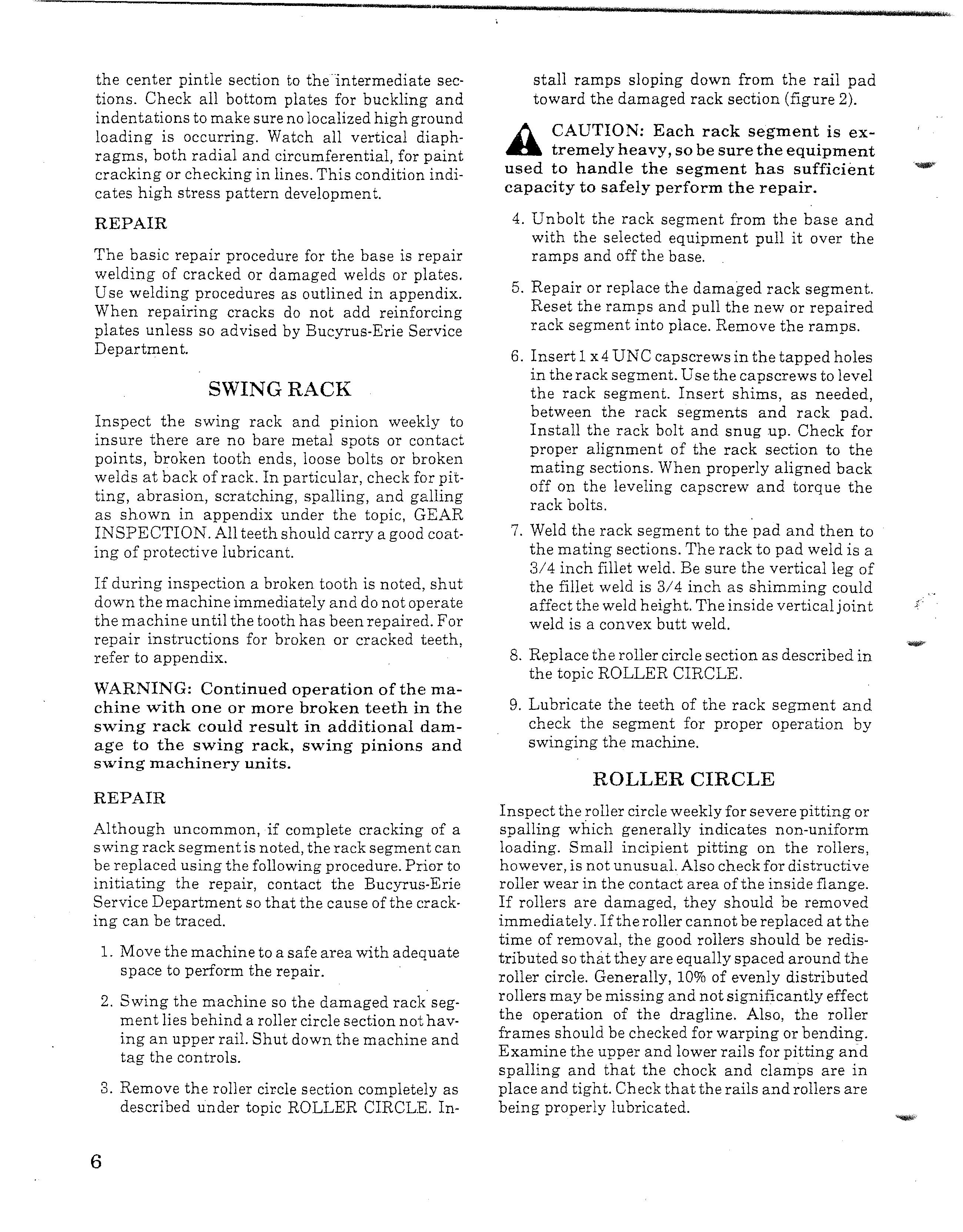
stall ramps sloping down from the rail pad toward the damaged rack section (figure 2).
/). CAUTION: Each rack segment is extremely heavy, so be sure the equipment used to handle the segment has sufficient capacity to saf-ely perform the repair.
4. Unbolt the rack segment from the base and with the selected equipment pull it over the ramps and off the base.
5. Repair or replace the damaged rack segment. Reset the ramps and pull the new or repaired rack segment into place. Remove the ramps.
6. Insert 1x4 UNC capscrews in the tapped holes in the rack segment. Use the capscrews to level the rack segment. Insert shims, as needed, between the rack segments and rack pad. Install the rack bolt and snug up. Check for proper alignment of the rack section to the mating sections. When properly aligned back off on the leveling capscrew and torque the rack bolts.
7. Weld the rack segment to the pad and then to the mating sections. The rack to pad weld is a 3/4 inch fillet weld. Be sure the vertical leg of the fillet weld is 3/4 inch as shimming could affect the weld height. The inside vertical joint weld is a convex butt weld.
8. Replace the roller circle section as described in the topic ROLLER CIRCLE.
9. Lubricate the teeth of the rack segment and check the segment for proper operation by swinging the machine.
ROLLER CIRCLE
Inspect the roller circle weekly for severe pitting or spalling which generally indicates non-uniform loading. Small incipient pitting on the rollers, however, is not unusual. Also check for distruetive roller wear in the contact area of the inside flange. lf rollers are damaged, they should be removed immedia tely. If the roller cannot be replaced at the time of removal, the good rollers should be redistributed so that they are equally spaced around the roller circle. Generally, 10% of evenly distributed rollers may be missing and not significantly effect the operation of the dragline. Also, the roller frames should be checked for warping or bending. Examine the upper and lower rails for pitting an.d spalling and that the chock and clamps are in place and tight. Check that the rails and rollers are being properly lubricated.
SWING RACK SECTION REMOVAL
FIGURE 2
REPAIR
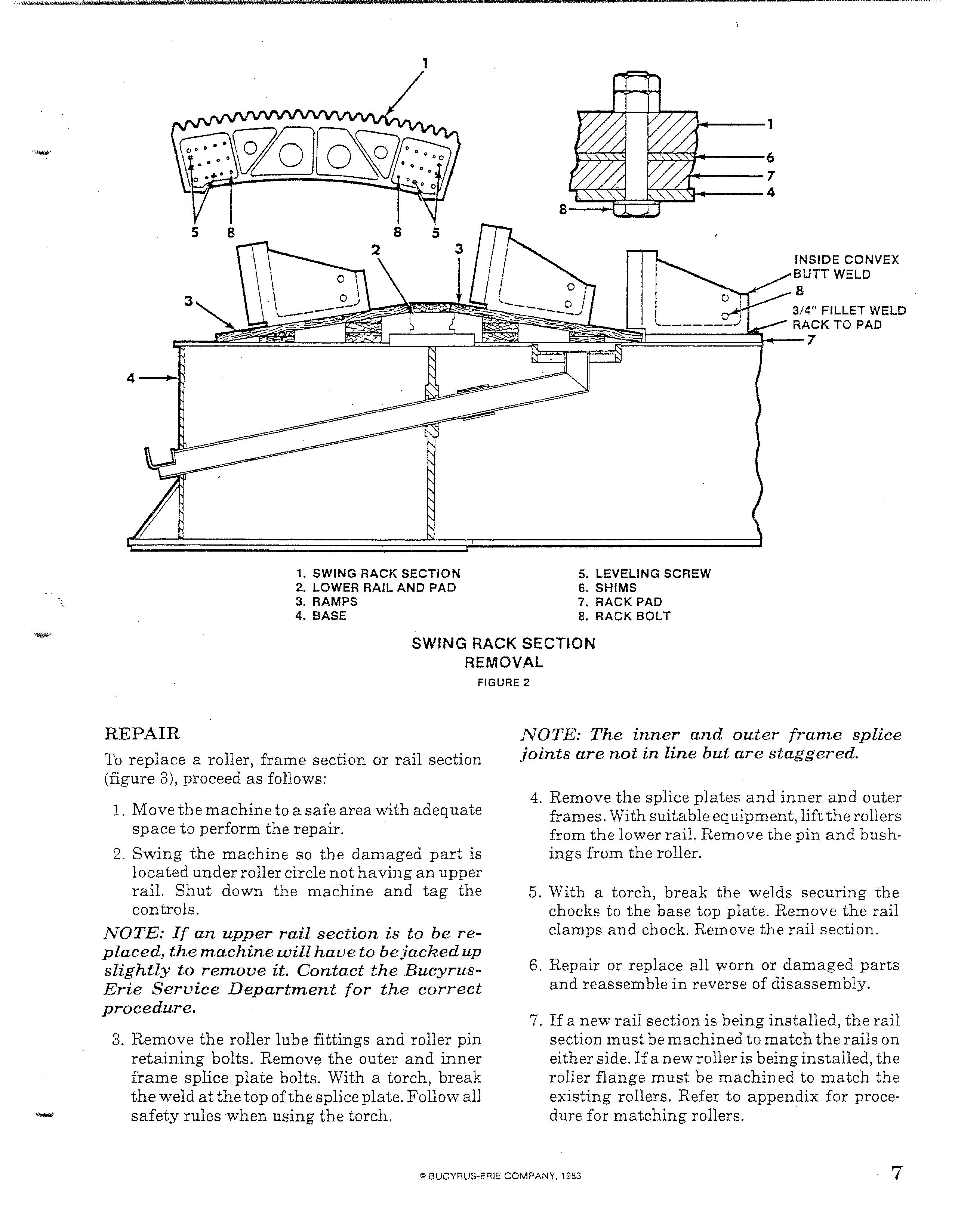
To replace a roller, frame section or rail section (figure 3), proceed as follows:
1. Move the machine to a safe area with adequate space to perform the repair.
2. Swing the machine so the damaged part is located under roller circle not ha ving an upper rail. Shut down the machine and tag the controls.
NOTE: If an upper rail section is to be replacedJ the machine will have to bejacked up slightly to remove it. Contact the BucyrusErie ServiceDepartment for the correct procedure.
3. Remove the roller lube fittings and roller pin retaining bolts. Remove the outer and inner frame splice plate bolts. With a torch, break the weld at the top of the splice plate. Follow all safety rules when using the torch.
NOTE: The inner and outer frame splice joints are not in line but are staggered.
4. Remove the splice plates and inner and outer frames. With suitable equipment, lift the rollers from the lower rail. Remove the pin and bushings from the roller.
6. With a torch, break the welds securing the chocks to the base top plate. Remove the rail clamps and chock. Remove the rail section.
6. Repair or replace all worn or damaged parts and reassemble in reverse of disassembly.
7. If a new rail section is being installed, the rail section must be machined to match the rails on either side. If a new roller is being installed, the roller flange must be machined to match the existing rollers. Refer to appendix for procedure for matching rollers.
• Thank you very much for reading the preview of the manual.
• You can download the complete manual from: www.heydownloads.com by clicking the link below
• Please note: If there is no response to CLICKING the link, please download this PDF first and then click on it.