FOREWORD
The purpose of this manual is to provide information concerning the mechanical maintenance of the 1260W Walking Dragline.

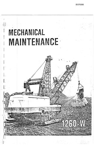
The Model 1260W consists of three major units, the lower works, the rotating deck and the front end equipment. The lower works provides a foundation for the revolving frame and contains the base, swing rack and roller circle. The rotating deck includes the revolving frame and machinery house. The machinery house encloses all ofthe hoist, swing, drag and propel machinery, and the electrical systems required to control machine functions. It also contains an air filtration system to minimize heat and dirt build-up in the machinery house. An elevated cab mounted on the house provides the machinery operator's station. The cab contains all machine operating controls. The front end equipment is comprised of the A-frame, fairlead, mast, boom, running ropes, boom structural strands, {lnd dragline bucket.
This manual consists offour chapters, each divided into sections. A table of contents is located in the front of the manual.
Throughout this manual the words CAUTION, WARNING and NOTE appear in bold face type. CAUTION is preceded by the safety alert symbol A and indicates that injury to personnel could occur if the proper procedures are not followed during operation or maintenance. Always read the CAUTION note carefully and use extreme care while performing that particular function.
WARNING indicates a possible hazard to the.machine or its components if the proper procedures are not followed. Whenever the word WARNING appears, special attention should be given to prevent possible equipment damage.
NOTE is used to stress a point or to give additional information concerning the procedure being discussed.
These CAUTION's and WARNING's are not all-inclusive. It is impossible for Bucyrus-Erie Company to know, evaluate, and advise maintenance and service personnel in every conceivable way a service operation might be performed and ofthe resulting possible hazardous consequences of each method. It is therefore extremely important that anyone who uses a service procedure or tool which is not recommended by Bucyrus-Erie Company to first satisfy himself that the service procedure or tool he chooses will not jeopardize his own safety, the safety of others, or cause machine or component damage.
Every effort has been made to make this manual as complete as possible at the time of printing. However, Bucyrus-Erie Company reserves the right to continually improve its products. For this reason changes may be made that are not in this manual.
MACHINE SERIAL NUMBER , BUCYRUS-ERIE COMPANY
General Olflces: South Milwaukee, Wisconsin, U.S.A•
•1M SPS 485
© BUCYRUS-ERIE COMPANY, 1985
I

\\ f""';-'

1\ I [I I II I I I l ! lei I I I I, ! I I I ! I I I I
CHAPTER 1- MECHANICAL MAINTENANCE PAGE Section 1 - MAINTENANCE PROCEDURE General .............................................•..................................... 1 Maintenance Schedules and Reports 1 Safety 2 General 2 In-Operation Maintenance ' 2 Precautions Before and During Maintenance Work 2 Section 2- LOWER WORKS Base 5 Center Pintle ' 6 S\ving Rack ............................................................................. .. 7 Roller Circle :................................................... .. 8 Lifting Hook and Hook Path 10 Section 3- ROTATING DECK Revolving Frame 13 Machinery Units 14 Hoist and Drag Machinery 14 Swing Machinery : 20 Propel Machinery :................. 30 Brakes - Style 4 and 5 38 Brakes - Style 7 : 41 Brakes - Style 2 44 Brakes - Style 6 47 Drag Rope Support Rollers 50 Machinery I'fouse and Cabs '" 50 Structural Members and Panels 50 Dynavane Air Cleaner 50 House Fans 50 House Fans (Propellair) 51 House Fans (Chicago Blower) 51 Auxiliary Hoists and Overhead Crane 52 Walkways and Stairways 54 Windshield Wiper 54 Operator's Seat 55 S\ving Control Unit 55 Section 4- FRONT END EQUIPMENT Boom 57 Upper and Lower Deflection Sheaves and Towers :. 60 Boom Point ' 60 Hoist Rope House Deflector Rollers 62 Mast 62 A-Frame 62 -------,-...
TABLE OF CONTENTS


Structural strands........................................................................... 63 A-Frame Safety Structural Strands : ; 65 Upper ,Lower and Intermediate Structural Strands............................... 65 Hoist and Drag Ropes..................................................................... 70 Hoist Rope Replacement. 71 Drag Rope Replacement.............................................................. 72 Fairlead .....................................................•................................ 74 Buffer Cylinder , 78 Dragline Bucket. 81 CHAPTER 2- AIR SYSTEM Section 1- GENERAL MAINTENANCE Safety .....................................................................•................... 85 Genera1. 85 Maintenance of Air System 85 Air Compressor........................................................................ 85 Air Lines :..................... 85 Air Tank 85 Air Line Lubricator 87 Air Line Filter 87 Air Line Regulator : 87 Anti-Freezer - Alcohol Type (Optional) 87 Solenoid Valves ,, 87 Pressure Switches 87 Air Dryer 87 Air Compressor - Leading Particulars and Description 88 Two Compressor Regulation Pane1. 88-5 :. '; .Section 2- COMPONENT MAINTENANCE ' Air Compressor(CompAirBroomWade)(6020E-13A) 89 Routine Maintenance and Schedule............................................... 89 Maintenance Procedures 90 Servicing Points and Maintenance Parts 91 W D' 92 IrIng Iagrams . Air Line Lubricators 93 Micro-Fog Lubricator 93 Oil Fog Lubricator(Type 10-002,3 oz. and 1/3 pint size) 93 Oil Fog Lubricator(Type 10-002, 1/2 pint size) 93 Automatic Drain Filter '.' 94 Anti-Freezer - Alcohol Type 96 Air Regulator : 96 Air Dryer.................................................................................... 97


l ;: [ 0" I [ I I1 CHAPTER 3- LUBRICATION Section 1 - GENERAL MAINTENANCE General 99 Lubrication Benchmarks , 99 Lubrication Charts " 100 Section 2 - AUTOMATIC SYSTEMS A System 107 '-B System 107 C System " 107 D System 108 E System 108 F Systeln ' 108 G System , " 108 H System " 108 I Systenl " 109 J System 109 K System 109 L System 109 Control Panels '" 109 PUlnps 109 Warning Devices '" '" 110 Cold Weather Equipment (Optional) : 110 Lubricant Drum Handling Equipment (Optional) ,lID Pumped Lubrication System on Swing Boxes 110-1/23 CHAPTER 4- TROUBLESHOOTING Base Components '" , : III Revolving Frame 112 Hoist, Drag, Swing and Propel Machinery 112 Machinery House and Cabs 113 Lubrication Systems 114 Air System 115 Air Compressor 115 Centrifugal U nloader ' .. 117 Air Line Regulator " 117 Air Lines and Storage Tank , 117 Air Line Lubricator 117 Automatic Drain Filter 117 Dynavane Air Cleaner 117 A-Frame 117 Mast 118 Boom 118 Dragline Bucket 118 Drag and Hoist Ropes " 119 Fairlead 119
• Thank you very much for reading the preview of the manual.
• You can download the complete manual from: www.heydownloads.com by clicking the link below
• Please note: If there is no response to CLICKING the link, please download this PDF first and then click on it.

CLICK HERE TO DOWNLOAD THE COMPLETE MANUAL
CLICK HERE TO DOWNLOAD THE COMPLETE MANUAL