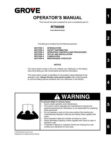
OPERATOR’S MANUAL
This manual has been prepared for and is considered part of -
RT9000E
Crane Model Number
This Manual is divided into the following sections:
SECTION 1 INTRODUCTION
SECTION 2 SAFETY INFORMATION
SECTION 3 OPERATING CONTROLS AND PROCEDURES
SECTION 4 SET-UP AND INSTALLATION
SECTION 5 LUBRICATION
SECTION 6 MAINTENANCE CHECKLIST
NOTICE
The crane serial number is the only method your distributor or the factory has of providing you with correct parts and service information.

The crane serial number is identified on the builder’s decal attached to the operator’s cab Always furnish crane serial number when ordering parts or communicating service problems with your distributor or the factory.
To prevent death or serious injury:
• Avoid unsafe operation and maintenance
• This crane must be operated and maintained by trained and experienced personnel Manitowoc is not responsible for qualifying these personnel
• Do not operate or work on this crane without first reading and understanding Operator’s Manual and Rating Plate supplied with crane
• Store Operator’s Manual in holder provided on crane.
• Attach laminated Capacity Charts supplied with crane to chain in operator’s cab
• If Operator’s Manual or Capacity Charts are missing from cab, contact your distributor for new ones
1 2 3 4 5 6 Published 2-27-2006 Control # 076-00
© 2005 Manitowoc Crane Group
• Thank you very much for reading the preview of the manual.
• You can download the complete manual from: www.heydownloads.com by clicking the link below
• Please note: If there is no response to CLICKING the link, please download this PDF first and then click on it.

CLICK HERE TO DOWNLOAD THE COMPLETE MANUAL
CLICK HERE TO DOWNLOAD THE COMPLETE MANUAL
To Contact Us:
Manitowoc Cranes, Inc.
2401 South 30th Street
Manitowoc, WI 54220

(920) 684-6621
(920) 683-6277 (fax)
Grove Worldwide
1565 Buchanan Trail East
P.O. Box 21
Shady Grove, PA 17256
(717) 597-8121
(717) 597-4062 (fax)
National Crane Corporation


1565 Buchanan Trail East
P O Box 21

Shady Grove, PA 17256
(717) 597-8121
(717) 597-4062 (fax)
Grove Worldwide
1565 Buchanan Trail East
P.O. Box 21
Shady Grove, PA 17256
(717) 597-8121
(717) 597-4062 (fax)
Technical Publications Field Service
Service Training Parts
Factory
See end of this manual for Alphabetical Index

TOC-1
T O C
RT9000E TABLE OF CONTENTS
SECTION 1. . . . . . . . . . . . . . . . . . . . . . . . . . . . . . . . . . . .INTRODUCTION General 1-1 Noise/Vibration Test Results 1-1 Noise Level Test Results Are As Follows: 1-1 Vibration Level Test Results Are As Follows: 1-1 SECTION 2. . . . . . . . . . . . . . . . . . . . . . . . . . . . . SAFETY INFORMATION Diesel Engine Exhaust 2-1 Battery Posts, Terminals, And Related Accessories 2-1 Safety Messages 2-1 General 2-1 Safety Alert Symbol 2-1 Signal Words 2-1 General 2-1 Operator’s Information. . . . . . . . . . . . . . . . . . . . . . . . . . . . . . . . . . . . . . . . . . . . . . . . . . . 2-2 Operational Aids 2-2 Operator’s Qualifications 2-3 Crane Stability/Structural Strength 2-3 Load Charts 2-4 Work Site 2-5 Lifting Operations 2-5 Counterweight 2-6 Multiple Crane Lifts 2-6 Load Moment Indication (LMI) Systems . . . . . . . . . . . . . . . . . . . . . . . . . . . . . . . . . . . . . 2-7 Two-Blocking 2-7 Work Area Definition System . . . . . . . . . . . . . . . . . . . . . . . . . . . . . . . . . . . . . . . . . . 2-7 Electrocution Hazard 2-7 Set-Up and Operation 2-8 Electrocution Hazard Devices 2-8 Electrical Contact . . . . . . . . . . . . . . . . . . . . . . . . . . . . . . . . . . . . . . . . . . . . . . . . . . . 2-9 Special Operating Conditions and Equipment 2-9 Crushing Hazards . . . . . . . . . . . . . . . . . . . . . . . . . . . . . . . . . . . . . . . . . . . . . . . . . . . . . 2-10 Personnel Handling 2-10 travel operation 2-11 Accidents 2-12 Maintenance 2-12 Service and Repairs 2-12 Lubrication 2-12 Tires 2-13 Wire Rope 2-13 Batteries 2-14 Engine 2-14 Work Practices 2-14 Crane Access 2-14 Job Preparation 2-14 Working 2-15 Lifting . . . . . . . . . . . . . . . . . . . . . . . . . . . . . . . . . . . . . . . . . . . . . . . . . . . . . . . . . . . 2-15 Hand Signals 2-16 Transporting The Crane. . . . . . . . . . . . . . . . . . . . . . . . . . . . . . . . . . . . . . . . . . . . . . . . . 2-17 Shut-Down 2-17 Boom Extension/Jib 2-17 Cold Weather Operation 2-17 Temperature Effects On Hydraulic Cylinders 2-18
TABLE OF CONTENTS RT9000E TOC-2 SECTION 3. . . . . . . . . . . OPERATING
AND
Controls And Indicators . . . . . . . . . . . . . . . . . . . . . . . . . . . . . . . . . . . . . . . . . . . . . . . . . 3-1 Defroster Switch 3-1 Hand Throttle Control . . . . . . . . . . . . . . . . . . . . . . . . . . . . . . . . . . . . . . . . . . . . . . . 3-1 Ignition Switch 3-1 Voltmeter 3-1 Transmission Oil Temperature Gauge 3-1 Heat Control Knob 3-1 Fan Control Switch 3-1 Park Brake Control Switch. . . . . . . . . . . . . . . . . . . . . . . . . . . . . . . . . . . . . . . . . . . . 3-1 Air Conditioner Control Switch (Optional) 3-5 Swing Brake Control Switch . . . . . . . . . . . . . . . . . . . . . . . . . . . . . . . . . . . . . . . . . . 3-5 Axle Differential Lock Control Switch (Optional) 3-5 Swing Speed Control Switch 3-5 Drive Axle Selector Switch 3-5 Cab Tilt Switch 3-5 Outrigger Control Switches 3-5 Work Light Switch . . . . . . . . . . . . . . . . . . . . . . . . . . . . . . . . . . . . . . . . . . . . . . . . . . 3-5 Headlights Switch 3-5 Boom Lights Switch (Optional) 3-6 Hazard Lights Switch 3-6 Hose Reel Brake On Indicator 3-6 Fuel Gauge 3-6 Engine Diagnostics Switches 3-6 Engine Coolant Temperature Gauge 3-6 Tachometer 3-6 Crane Function Power Switch . . . . . . . . . . . . . . . . . . . . . . . . . . . . . . . . . . . . . . . . . 3-6 Outriggers Extend/Retract Switch 3-6 Load Moment Indicating (LMI) and Work Area Definition System Control Panel 3-7 Auto/Manual Boom Telescope Mode Switch 3-7 Center Mid/Inner Mid Boom Telescope Section Select Switch 3-7 Rear Steer Control Switch 3-7 Auxiliary Hoist Speed Selector Switch. . . . . . . . . . . . . . . . . . . . . . . . . . . . . . . . . . . 3-7 Swing Control Lever 3-7 Turn Signal Lever and Windshield Wiper/Washer controls . . . . . . . . . . . . . . . . . . . 3-7 Bubble Level Indicator 3-7 Cab Circulating Fan 3-7 Swing Brake Pedal 3-7 Telescope Control Foot Pedal 3-8 Windshield Wiper 3-8 Defroster Fan. . . . . . . . . . . . . . . . . . . . . . . . . . . . . . . . . . . . . . . . . . . . . . . . . . . . . . 3-8 Service Brake Foot Pedal 3-8 Spotlight (Optional) . . . . . . . . . . . . . . . . . . . . . . . . . . . . . . . . . . . . . . . . . . . . . . . . . 3-8 Foot Throttle Pedal 3-8 Transmission Shift Lever 3-8 Circuit Breaker Panel 3-8 Pin Swing Lock Control (Pin Type) 3-8 Hoist Rotation Indicators 3-8 Main Hoist Control Lever 3-8 360 Degree Swing Lock Control (Positive Lock Type) 3-8 Main Hoist Speed Selector Switch 3-8 Engine and System Diagnostic Connector (Not Shown) . . . . . . . . . . . . . . . . . . . . . 3-9 Luffing Jib Raise/Lower Switch 3-9 Luffing Jib On/Off Switch 3-9 Seat Switch (Not Shown) 3-9 Cab Dome Light 3-9
CONTROLS
PROCEDURES
TOC-3
T
C Fire Extinguisher. . . . . . . . . . . . . . . . . . . . . . . . . . . . . . . . . . . . . . . . . . . . . . . . . . . . 3-9 Boom Lift Control Lever 3-9 12 VDC Accessory Outlet 3-9 Auxiliary Hoist Control Lever 3-9 Horn 3-9 Right Turn Signal Indicator 3-9 Left Turn Signal Indicator 3-9 Rear Wheels Not Centered Indicator 3-9 Hoist 3rd Wrap Indicator (Optional W/CE) 3-9 Engine Stop Indicator . . . . . . . . . . . . . . . . . . . . . . . . . . . . . . . . . . . . . . . . . . . . . . . . 3-9 Engine Warning Indicator 3-10 Engine Service Indicator 3-10 Wait To Start Indicator 3-10 Low Brake Pressure Indicator 3-10 Transmission Service Indicator (XMSN) 3-10 Water In Fuel Indicator . . . . . . . . . . . . . . . . . . . . . . . . . . . . . . . . . . . . . . . . . . . . . . 3-10 Boom Not Sync Indicator 3-10 Throttle Mode Switch . . . . . . . . . . . . . . . . . . . . . . . . . . . . . . . . . . . . . . . . . . . . . . . 3-10 Hourmeter (Not Shown) 3-10 Skylight Wiper (Not Shown) 3-10 Backup Alarm (Not Shown) 3-10 Armrest Switch (Not Shown) 3-10 Boom Telescope Mode A/B Select Switch 3-10 Low Steer Pressure Indicator (CE Option) . . . . . . . . . . . . . . . . . . . . . . . . . . . . . . . 3-11 Electrical System Diagnostic Indicator 3-11 Operating Procedures . . . . . . . . . . . . . . . . . . . . . . . . . . . . . . . . . . . . . . . . . . . . . . . . . . 3-12 Pre-Starting Checks 3-12 Cold Weather Operation 3-12 Engine Operation 3-12 Crane Travel Operation 3-14 General Crane Operation 3-18 Using Your Load Chart 3-19 Crane Functions 3-19 SECTION 4. . . . . . . . . . . . . . . . . . . . . . . . . SET-UP AND INSTALLATION General 4-1 Installing Cable On The Hoist 4-1 Cable Reeving 4-1 Standard Counterweight And Auxiliary Hoist Mounting Structure (Figure 4-3) 4-4 Removal 4-4 Installation 4-4 Heavy Counterweight Assembly And Auxiliary Hoist Mounting Structure (Figure 4-3) 4-5 Removal 4-5 Installation 4-8 Outrigger Removal and Installation 4-9 Bleed Valve Operation 4-9 Procedure 4-9 Removal 4-9 Installation. . . . . . . . . . . . . . . . . . . . . . . . . . . . . . . . . . . . . . . . . . . . . . . . . . . . . . . . . 4-9 Erecting And Stowing The Swingaway Boom Extension 4-10 Erecting. . . . . . . . . . . . . . . . . . . . . . . . . . . . . . . . . . . . . . . . . . . . . . . . . . . . . . . . . . 4-10 Stowing 4-16 Connecting and Disconnecting the Hydraulic Boom Extension 4-17 Connecting 4-17 Disconnecting . . . . . . . . . . . . . . . . . . . . . . . . . . . . . . . . . . . . . . . . . . . . . . . . . . . . . 4-17 Swingaway Mounting Adjustment 4-18
RT9000E TABLE OF CONTENTS
O
TABLE OF CONTENTS RT9000E TOC-4 Boom Extension (With Inserts) . . . . . . . . . . . . . . . . . . . . . . . . . . . . . . . . . . . . . . . 4-19 Assembly of Boom Extensions 4-19 Checklists For Rigging Work 4-20 Description of Rigging Work 4-23 Installing/Removing Two-Stage Swingaway Lattice Extension for Boom Extension 4-24 Hydraulic Connection On the Boom Extension (If Unit Is Equipped With Hydraulic Luffing Boom Extension) 4-25 Electrical Connection On the Boom Extension 4-25 Folding Out/In the Deflection Sheaves On the 8 m Sections. . . . . . . . . . . . . . . . . 4-26 Positioning/Removing the Hoist Cable 4-27 SECTION 5. . . . . . . . . . . . . . . . . . . . . . . . . . . . . . . . . . . . . LUBRICATION general 5-1 Arctic Conditions Below -18°C (0°F) 5-1 lubrication points 5-1 Surface Protection for Cylinder Rods 5-1 Wire Rope Lubrication 5-10 SECTION 6. . . . . . . . . . . . . . . . . . . . . . . . . .MAINTENANCE CHECKLIST General 6-1 Instructions 6-1
SECTION 1 INTRODUCTION
1-i 1
TABLE OF CONTENTS General 1-1 Noise/Vibration Test Results . . . . . . . . . . . . . . . . . . . . . . . . . . . . . . . . . . . . . . . . . . . . . . 1-1 Noise Level Test Results Are As Follows: 1-1 Vibration Level Test Results Are As Follows: . . . . . . . . . . . . . . . . . . . . . . . . . . . . . . 1-1
INTRODUCTION RT9000E OPERATOR’S MANUAL 1-ii
SECTION 1 INTRODUCTION
GENERAL
NOTE: Throughout this handbook, reference is made to left, right, front, and rear when describing locations These reference locations are to be considered as those viewed from the operator’s seat with the superstructure facing forward over the front of the carrier frame
Basic nomenclature is shown in (Figure 1-1)
This Handbook provides important information for the operator of the Model RT9000E Series Grove Crane
The rough terrain crane incorporates an all welded steel frame, using planetary drive axles to provide four-wheel drive Axle steering is accomplished utilizing hydraulic steer cylinders The engine is mounted at the rear of the crane and provides motive power through a six speed forward and reverse transmission Hydraulic, double box, sliding beam outriggers are removable.
The carrier frame incorporates an integral fifth wheel, to which the rear axle is mounted, to provide axle oscillation
Axle oscillation lockout is automatic when the superstructure rotates from the travel position
The superstructure is capable of 360°rotation in either direction. All crane functions are controlled from the fully-
enclosed cab mounted on the superstructure The crane is equipped with a five-section, full power, sequenced and synchronized boom. Additional reach is obtained by utilizing an optional swingaway boom extension Lifting is provided by a main and auxiliary hoist.
NOISE/VIBRATION TEST RESULTS
Noise Level Test Results Are As Follows:
• At the operator’s station with closed cab operation, the value is 82 5 dBA maximum when measured at 114.4dBa(A) according to the directives 79/113/EEC and Kebomatief 27 and 93 0 dBA with open cab operation
Vibration Level Test Results Are As Follows:
• At the operator’s station with closed cab operation, vibration levels are less than 0 5 m/s/s for Whole Body Vibration exposure and are less than 2.5 m/s/s for Hand Arm Vibration exposure when measured according to 89/392/EEC Community Legislation on Machinery per standard ISO 2631/1 - Evaluation of Human Exposure to Work Body Vibration, ISO 5349 - Guidelines for the Measurement and Assessment of Human Exposure to Hand Transmitted Vibrations, and ISO/DIS 8041Human Response Vibration Measuring Instrumentation
1-1
RT9000E OPERATOR’S MANUAL INTRODUCTION 1


INTRODUCTION RT9000E OPERATOR’S MANUAL 1-2 6018-1
6018-4
1 2 3 4 5 7 8 5 7 6 1 10 9 11 12 13 14 15 16 7 17 20 18 7 19
FIGURE 1-1
1-3
INTRODUCTION 1 Item Description 1 Counterweight 2 Spotlight 3 Cab 4 Work Light 5 Outrigger Float 6 Valve Cover 7 Outrigger Jack Cylinder 8 Steps 9 Auxiliary Hoist 10 Main Hoist Item Description 11 Boom Pivot 12 Swingaway Nose 13 Lift Cylinder 14 Boom Nose Sheaves 15 Swingaway 16 Auxiliary Boom Nose 17 Front Axle 18 Rear Axle 19 Hydraulic Tank 20 Hydraulic/Transmission Oil Cooler
RT9000E OPERATOR’S MANUAL


INTRODUCTION RT9000E OPERATOR’S MANUAL 1-4
6018-3
6018-2
1 1 2 3 4 6 11 10 9 7 5 7 4 6 23 9 12 2 13 14 17 18 20 19 21 16 22 16 5 8 15
FIGURE 1-1 continued
1-5
INTRODUCTION 1 Item Description 1 Swingaway Extension 2 Boom 3 Hydraulic Tank 4 Main Hoist 5 Auxiliary Hoist 6 Counterweight 7 Air Conditioning Components 8 Windshield Washer Fluid Container 9 Cab 10 Work Light 11 Spotlight 12 Lift Cylinder Item Description 13 Boom Sheaves 14 Auxiliary Boom Nose 15 Outrigger Jack Cylinder 16 Outrigger Float 17 Front Axle 18 Fuel Tank 19 Fuel Water Separator 20 Battery 21 Rear Axle 22 Muffler 23 Boom Pivot
RT9000E OPERATOR’S MANUAL
• Thank you very much for reading the preview of the manual.
• You can download the complete manual from: www.heydownloads.com by clicking the link below
• Please note: If there is no response to CLICKING the link, please download this PDF first and then click on it.
CLICK HERE TO DOWNLOAD THE COMPLETE MANUAL
CLICK HERE TO DOWNLOAD THE COMPLETE MANUAL