10 minute read
Clinical


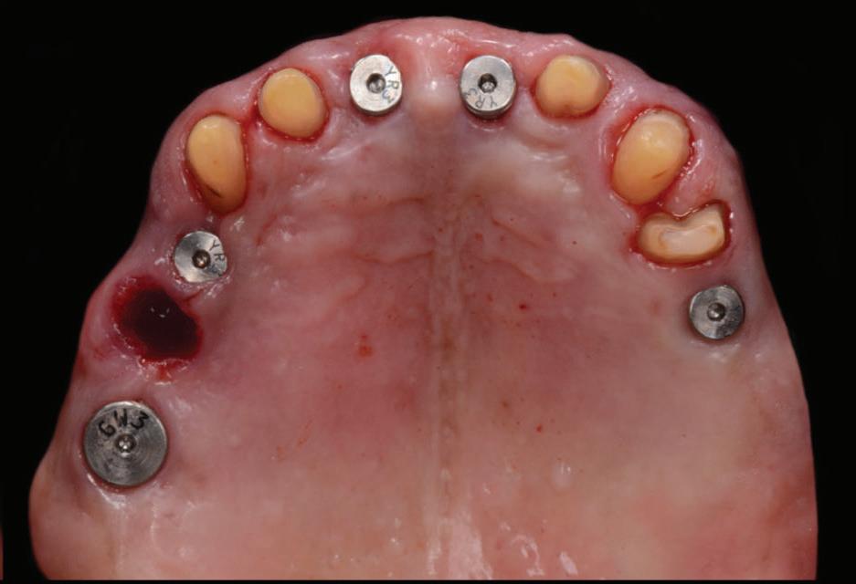
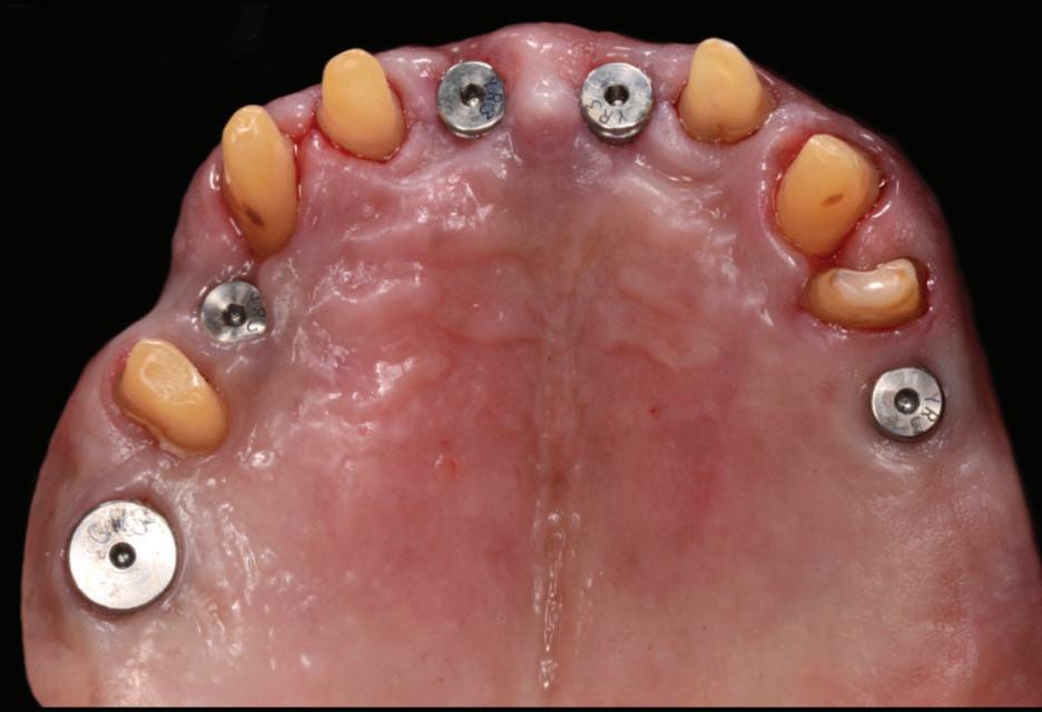
Figure 6: Five implant fixtures were placed using a fully guided surgical protocol.
Figure 7: A flap was raised in the 11 region as buccal bone grafting was required due to a bony defect.
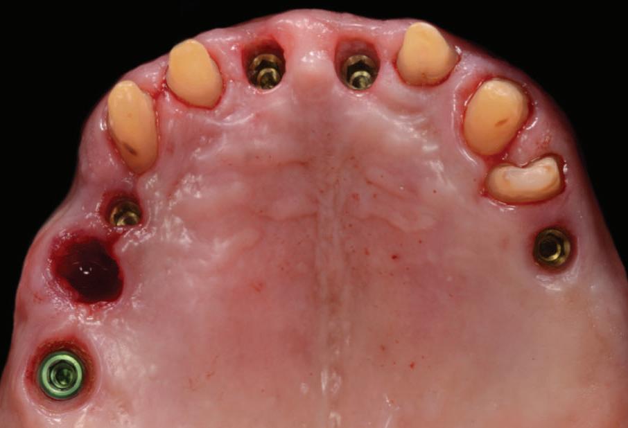
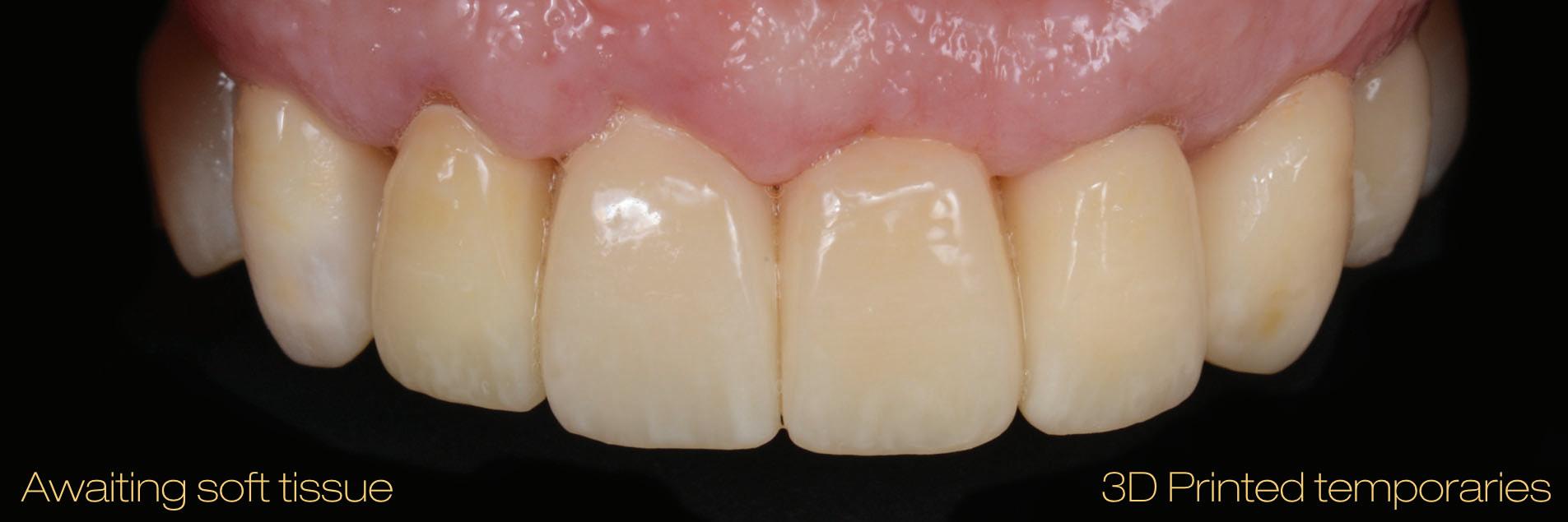
Figure 8: Immediate post-operative following guided implant surgery and temporary cementation of the provisional fixed bridge printed from GC Temp PRINT (medium shade). Figure 9: During the healing phase, tooth 24 developed pulpal necrosis and was endodontically treated.
and fixed to the printed guide/framework.
The design of the previous PFM was also copied and replicated in the digital planning of the temporary bridge. It was then printed using the Asiga Max UV and GC Temp PRINT (medium shade) set at 50µm on the 3D printer.
The following clinical procedures were then completed on the day of implant surgery: • All five implant fixtures were placed following a fully guided surgical protocol with the surgical guide (Fig. 6) and primary stability was confirmed. • A flap was raised in the 11-21 region, a bone graft with
bovine cancellous particulate was placed and covered with a porcine collagen membrane. Cover screws were placed and primary closure was established after a relieving incision and closed with PTFE sutures. At the other implant sites (16, 14 and 25), healing abutments were placed (Fig. 7). • The 3D-printed temporary bridge was then cemented with
GC Fuji TEMP LT on the remaining natural teeth (Fig. 8). A healing period of 16 weeks allowed complete osseointegration of the implant fixtures. During this period, tooth 24 (upper left first premolar) developed signs and symptoms of pulpal necrosis. Hence, it was endodontically treated (Fig. 9).
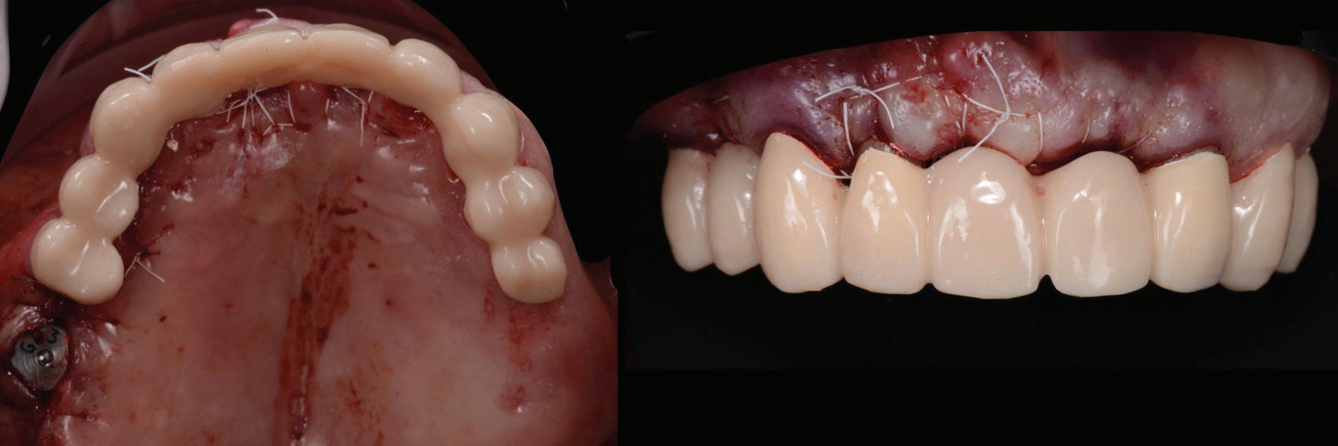
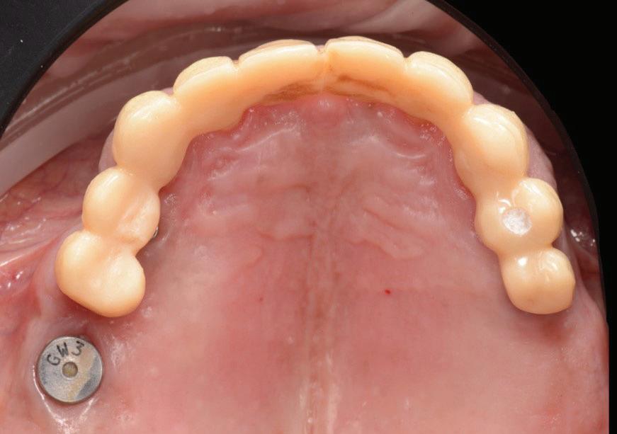
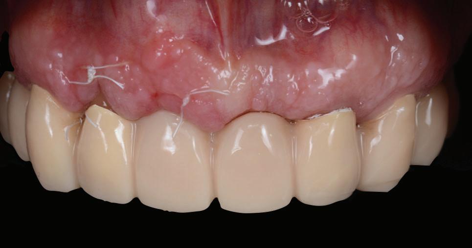
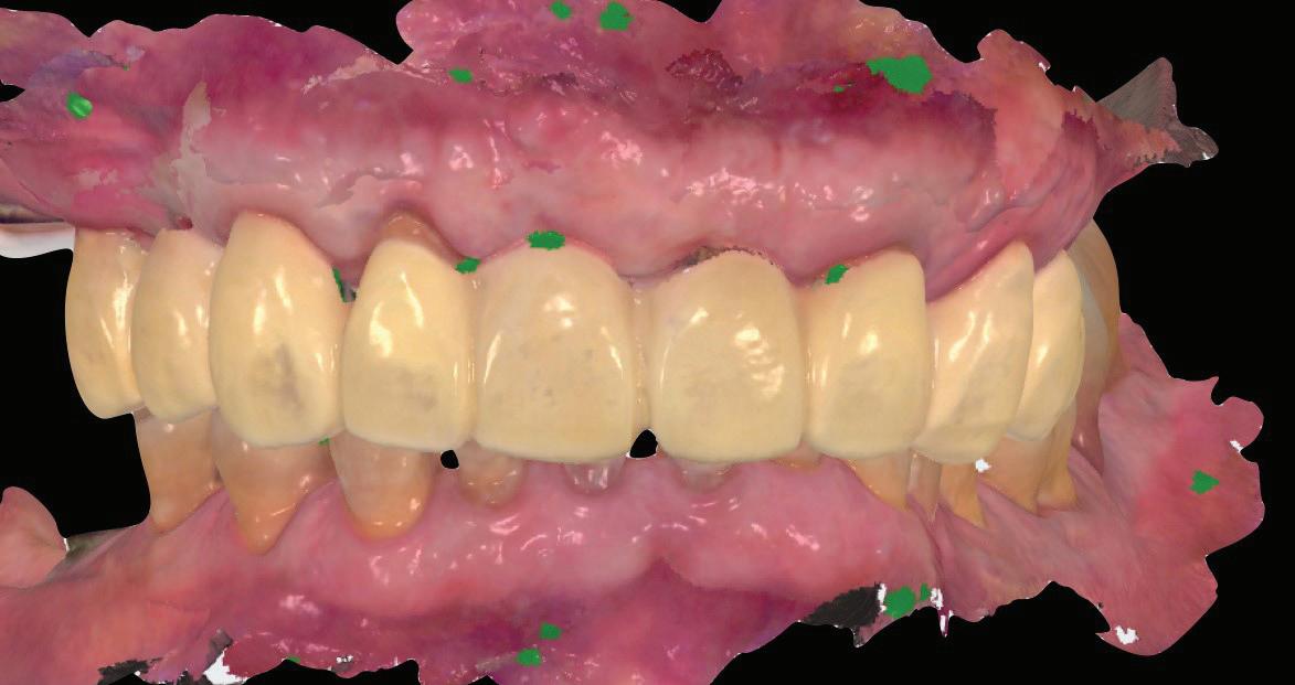
Figure 10: View at 10 days after implant surgery. Figure 11: Pre-operative surface scan.
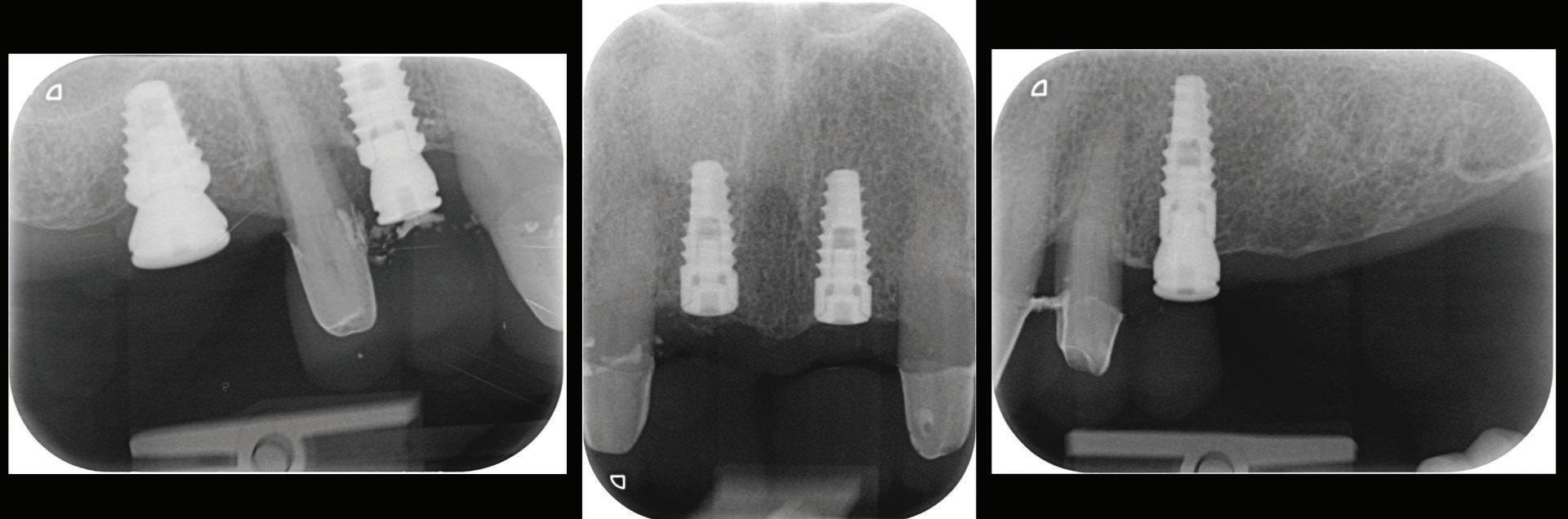
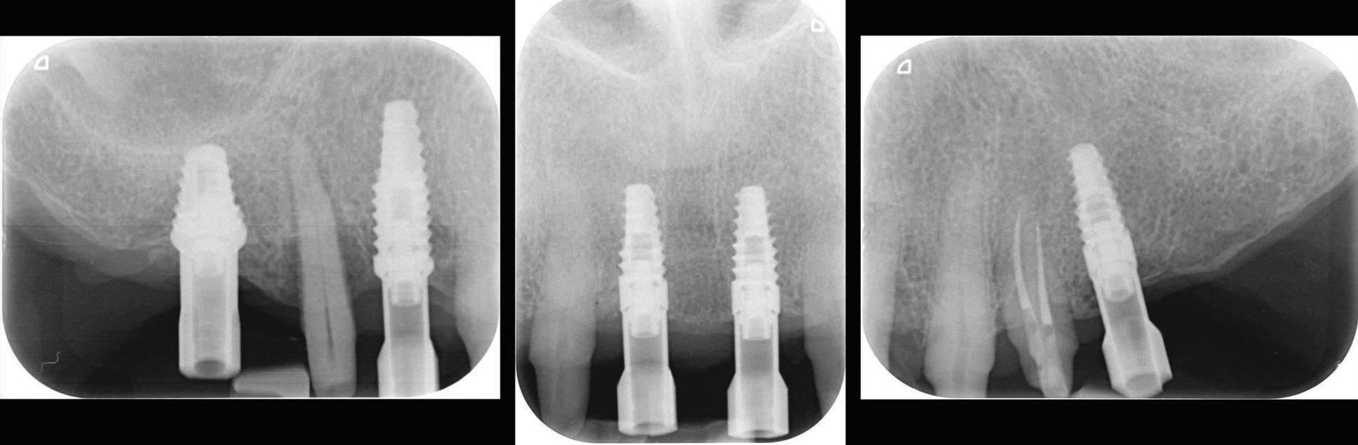
Figure 12: Periapical radiographs to verify the seat of the digital scan bodies.
Second Provisionalization Phase after Implant Integration.
Once the 16-week healing phase was completed and the fixtures were integrated, the restorative phase could be initiated. The patient confirmed that he was happy with the shape and occlusion of the initial temporary bridge (Fig. 10). The aesthetic and occlusal scheme could therefore be replicated in the second phase of provisionalization.
A pre-preparation IOS was taken with the healing abutment and temporary bridge in situ (Fig. 11).
The temporary bridge was then removed and preparation of the abutment teeth finalized and re-margined to the healed gingival tissue levels.
Stage 2 implant surgery on the 11 and 21 sites was completed using a soft tissue diode laser. The implants were exposed and cover screws removed.
An emergence profile scan was taken immediately after the healing abutments were removed to record gingival contours around the implant before any collapse of the tissues. Next, the full upper arch was scanned with digital scan bodies in place to capture the implant position accurately (Fig. 12).
All other prosthodontic records including the bite registration and the opposing arch were also captured with the intra-oral scanner before placing the temporary bridge back. All IOS were taken following the “Mak optimised scan strategy” (MOSS), allowing accurate stitching of IOS images. In soft tissue “pink” areas, the availability of landmarks is often limited; MOSS uses a specific scan path with or without markers for an enhanced scan accuracy and was especially designed for cases with few teeth to correlate to.
All the digital data was then sent to the ceramist for the fabrication the second set of provisional restorations. Provisional restorations were printed with GC Temp PRINT and characterised with OPTIGLAZE color (GC). Temporary abutment cylinders were utilised for the implant-retained restorations. The contours of the 11 and 21 implant-retained provisionals as well as the pontic of 15 were designed and fabricated to shape the soft tissues for optimal support and
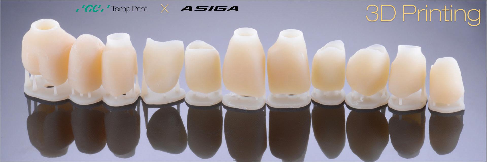
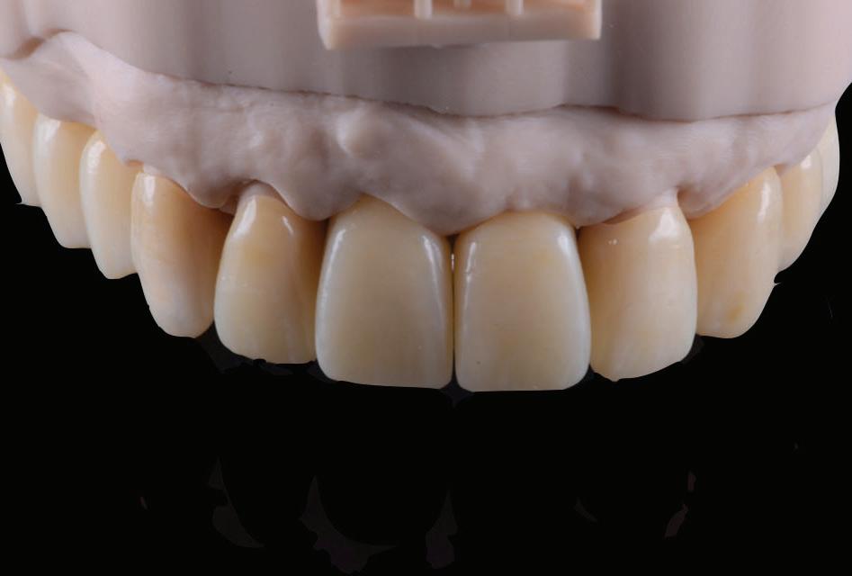
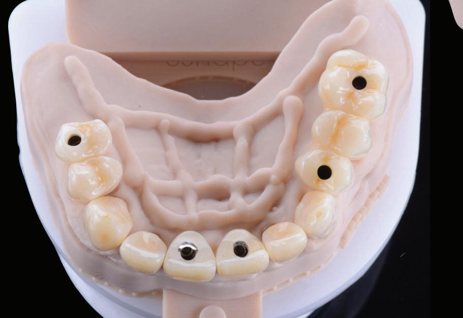
Figure 13: Second set of provisional restorations printed with GC Temp PRINT (medium shade) using the Asiga Max UV 3D printer.
Figure 14: Completed provisional crowns, implant retained crowns and bridge, characterised with OPTIGLAZE color (GC) – Dental technician: Brad Groblar, Oral Dynamics, New Zealand.
Figure 15: Completed provisionals fitted onto the printed models to allow the refinement of the contact points and occlusal contacts. Figure 16: (a) After removal of the temporary bridge from the first provisionalization phase. (b) Tooth 15 was extracted. Figure 17: (a) Healing abutments were removed and (b) the second set of temporary restorations was placed.
(Figs. 13-15).
Following removal of the temporary bridge, all the abutments were cleaned and the tooth 15 was extracted (Fig. 16). The provisional implant restorations, fabricated with direct screw access were torqued to the manufacturer’s recommendation. All other temporary printed restorations were cemented with FujiTemp (GC) (Figs. 17-19).
The soft tissues were prosthetically shaped and allowed to
15 16a 17a

16b 17b

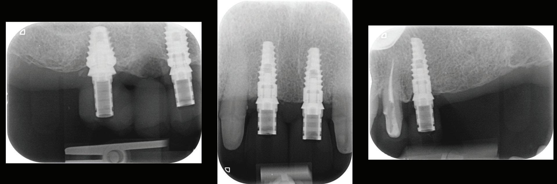
Figure 18: Periapical radiographs to verify the seat of the implant-retained provisional restorations.
Figure 19: Immediate post-operative view of the inserted provisionals.
heal for a period of 3 months before the finalisation of the rehabilitation with the definitive restorations.
Conclusion
The case presented illustrates how advances in digital technologies can provide clinicians with the tools for diagnosis, treatment planning, the execution and provision of dental restorative procedures in a truly transformative way.
Simplification of clinical protocols, increased accuracy over conventional analogue techniques and improved patient comfort and outcomes are compelling reasons of the benefits of a full digital workflow in the field of restorative and implant dentistry.
Reprinted with permission by GC get connected.

Management of the MB2
Kreena Patel1
1 Kreena Patel, BDS(Hons), MJDF RCS(Eng), MClinDent (Endodontology), MEndo RCS(Edin). Specialist in Endodontics. Lecturer on the Endodontic specialist programme, King’s College London Private Practice, Surrey and Berkshire, UK. @kreenaspecialistendodontics. The MB2 or ‘fourth’ canal has a quite the reputation for being challenging to locate and negotiate. Kreena Patel discusses facts about the MB2 and clinical tips for successfully managing it.
Importance
Just how important is this little canal? This question is often debated among clinicians as some feel root canal treatment can be carried out successfully without treating MB2.
Successful endodontic treatment relies on locating, disinfecting and obturating all the canals. Studies have shown the incidence of MB2 canals is roughly 90% in maxillary first molars and 60% in maxillary second molars. Therefore, the majority of maxillary molars contain four canals and we should start root canal treatment of these teeth with this in mind.
There are often multiple ports of communication between MB1 and MB2. The MB2 can join MB1 along its path or terminate via a separate apical foramen (Figure 1 and Figure 2). Rarely, there can be an MB3 canal present (Figure 3).
1a 1b 1c
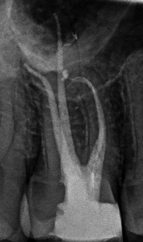
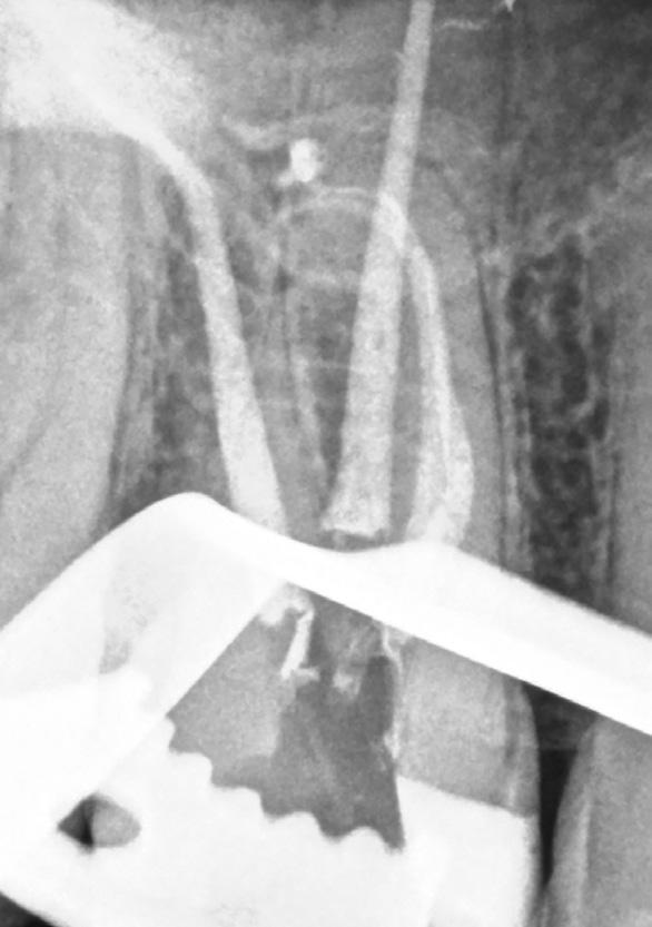
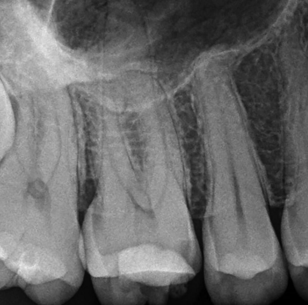
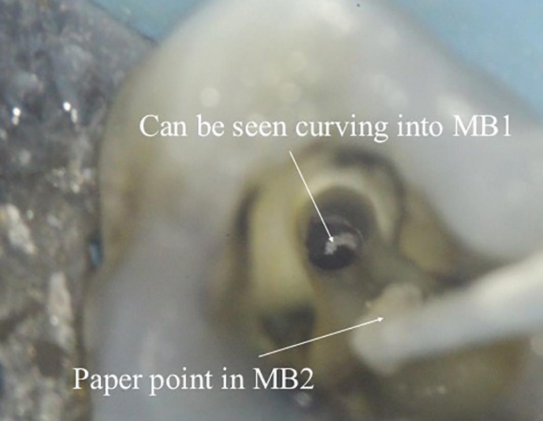
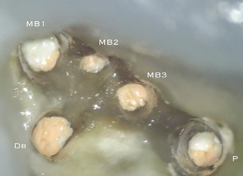
Figure 2: A paper point has been placed in the MB2, and can be seen appearing in MB1 where the canals join Figure 3: Upper second maxillary molar with MB1, MB2 and MB3
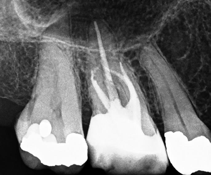
A missed MB2 canal is one of the main causes of endodontic failure in maxillary molars. In cases of irreversible pulpitis, it may be responsible for ongoing temperature sensitivity, and in necrotic cases, residual bacteria will increase the risk of infection (Figure 4).
CBCT
Cone beam CT has become a very useful tool in endodontics because it allows us to see root canal morphology is three dimensions. It is important to note there are large differences in scan quality obtained by various CBCT machines; a highresolution small volume scan is necessary to visualise the fine details required for endodontics. CBCT has been shown to be a reliable tool for detecting MB2 canals and assessing their path up the root (Figure 5). However, studies have shown MB2 canals are still sometimes located clinically even when they are not seen on the scan (Blattner et al, 2010; Parker et al, 2017).
Location
Magnification and lighting make all the difference when trying to locate MB2. Studies have shown that the frequency of MB2 canal detection for microscope, dental loupes and no magnification were 71.1%, 62.5% and 17.2% respectively (Buhrley et al, 2002). The experience of the operator and time spent searching for the canal have also been shown to be important factors.
4a 4b 4c
Figures 4a, 4b and 4c: Patient was referred for the root canal retreatment of UR6. The tooth had been treated privately with her general dentist three years ago; the root canal treatment had been carried out to a good standard (under rubber dam isolation, three canals cleaned, shaped, disinfected using sodium hypochlorite and obturated to length). The patient did not have significant pain but the tooth did not ‘feel right’ and was affecting her function. Root canal retreatment was carried out and an additional MB2 canal was located. The patient’s symptoms settled immediately following treatment and she was advised to proceed with a cuspal coverage restoration
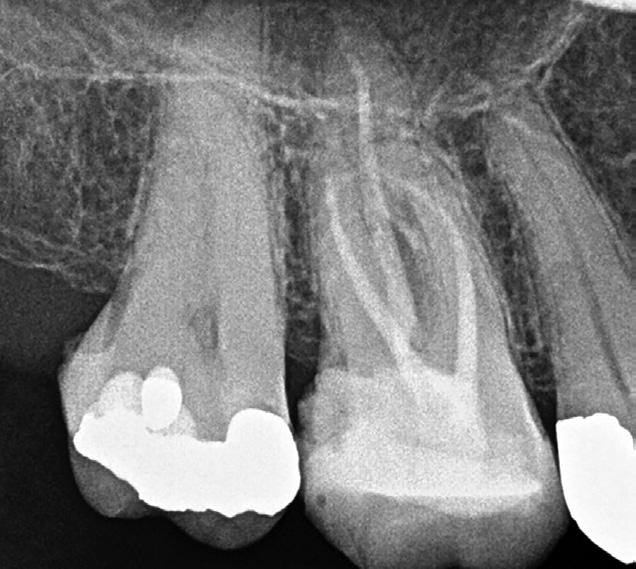
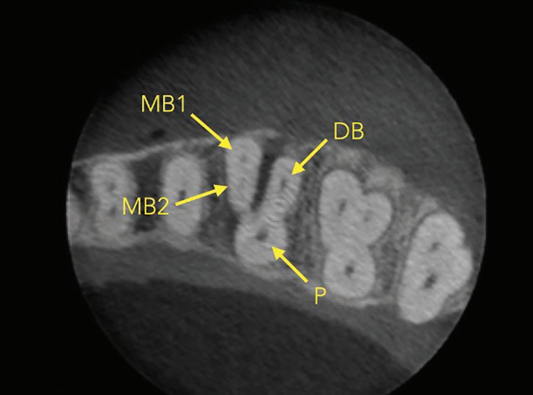
Figure 5: CBCT image (axial view) of a maxillary molar highlighting the presence of two canals in the MB root. Sometimes the MB2 canal is more calcified and cannot be seen clearly. If the MB root form is oval and the MB1 is asymmetrically positioned then there will still likely be an MB2 canal present
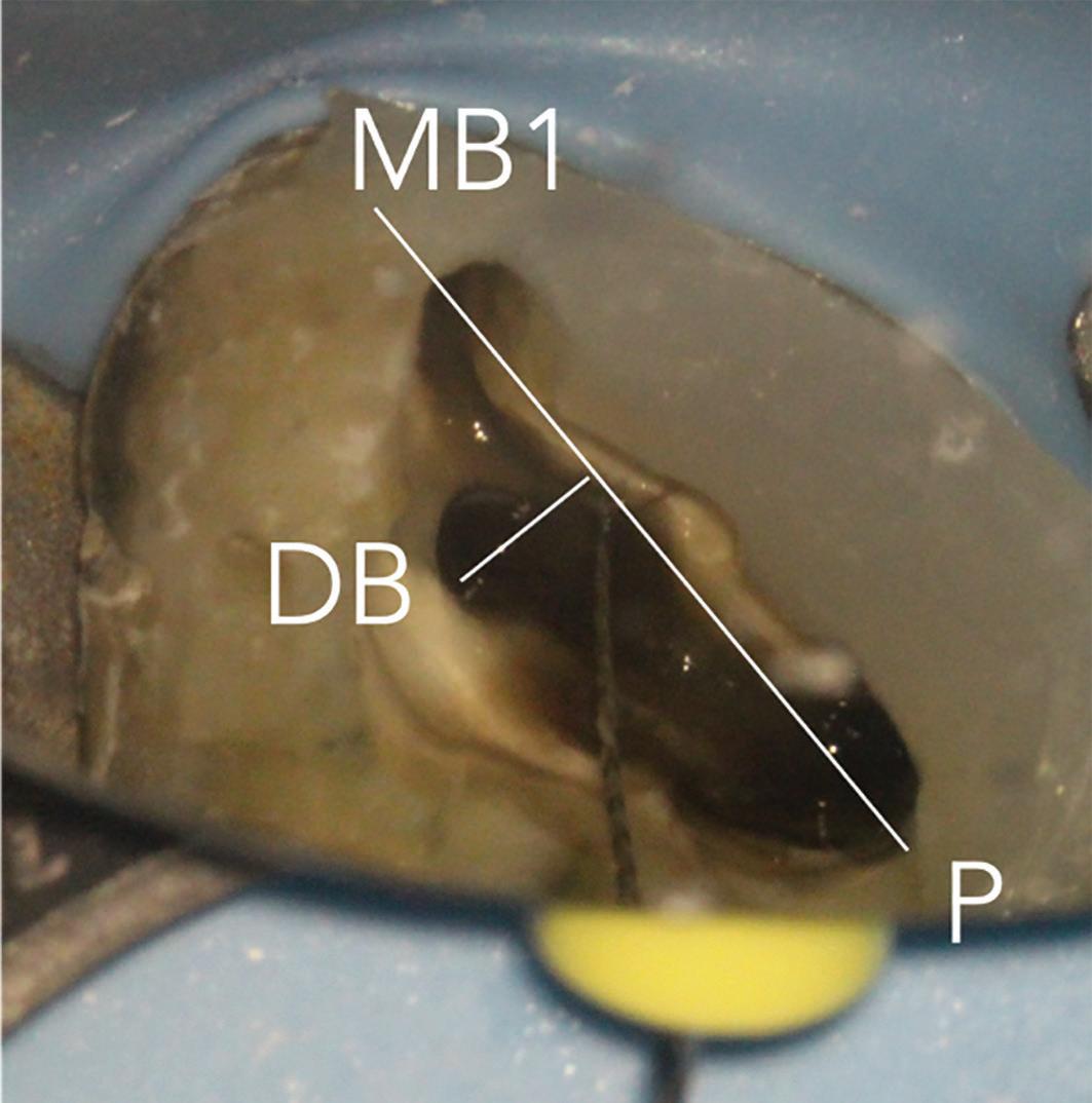
6a: The MB2 orifice normally lies at the juncture of these two lines
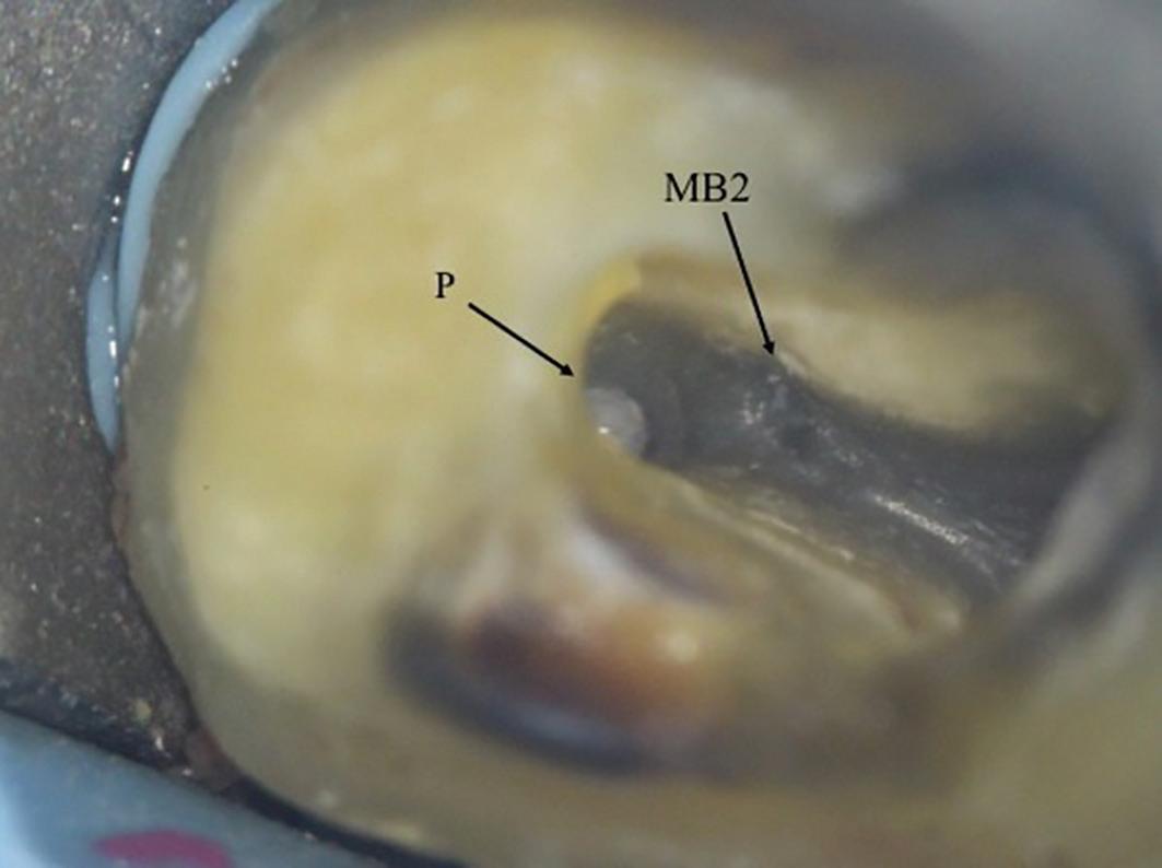
The pulp floor has developmental root fusion lines which are darker; these can provide a road map for locating canals because of where the orifices lie (Krasner and Rankow, 2004). The MB2 canal is commonly located within the developmental groove between MB1 and palatal orifices. Envisage a line joining the MB1 and palatal canal, and draw another line from DB to this line – in the majority of cases MB2 is located at this juncture, and a few millimetres away from the MB1 orifice (Figure 6). A sharp DG16 probe is essential for exploring the area and locating the orifice. Less frequently, the MB2 orifice can lie closer to the palatal orifice (Figure 7) or within the MB1 orifice itself (Figure 8).
The orifice lies at the junction of the pulp floor and mesial wall, and is frequently covered by a mesial lip or ‘shelf’
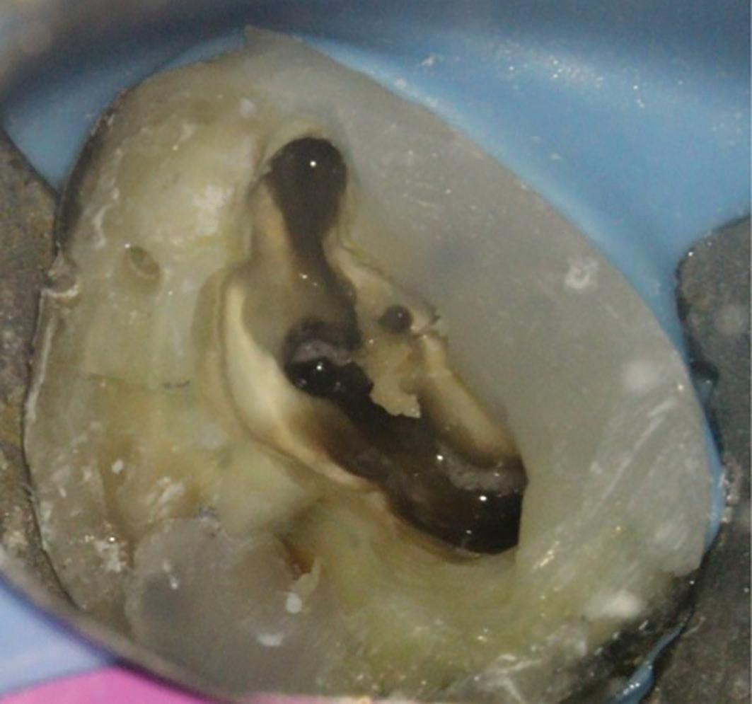
6b: MB2 located with a hand file