THE BUSINESS MAGAZINE FOR THE ELECTRICAL TRADE


8 The key things electricians need to know to stay ahead of the ‘prosumer’ curve
11 Where should fire detectors be used?
14 ‘Codebreaking’ the latest on-site finds from electricians on the job
17 Guidance on the installation of twisted pair network cables
20 The five ultimate leadership tips that trade business owners should know
24 Why is it important to enclose single insulated cables?
26 Answering some of the common questions around the use of SPDs, following Amendment 2
28 The continued importance of safe isolation, Lockout & Tagout
32 Taking a closer look at the requirements for automatic disconnection in case of a fault
34 Why business success is based on consistency rather than greatness
37 Looking at some of the component parts that may be employed in an electrical energy storage system (EESS)
39 What type of lighting is best for use on snooker tables?
43 How should RCBOs be used in the workplace?
44 A closer look at Part F of the Building Regulations for commercial and industrial buildings
46 ‘Codebreaking’ the latest on-site finds from electricians on the job
48 Identifying the different types of control cables and why a new scheme should help to improve the quality of cables being sourced and used
52 Understanding the function(s) of a communication Bus system and its ability to permit interconnected control of devices using twisted multi-pair cable
54 Considering the necessity of maintaining signal integrity for life safety services
56 What is a ‘hazardous area’?
58 ‘Codebreaking’ the latest on-site finds from electricians on the job 62 Five ways to improve your business
63 How to check if the fire qualification you’re signed up for is government-approved 64 Understanding the
66 The dangers involved with electric arcs and the considerations electricians must make in their choice of protective wear
86 Unified Glare Ratings explained
89 Taking a closer look at the requirements for carrying out risk assessments
93 Summarising the requirements in Section 704 for the use of reduced low voltage (RLV) supplies on building and construction sites
96 What is power factor and what purpose does it serve?
98 What makes a fire installation compliant?
100 ‘Codebreaking’ the latest on-site finds from electricians on the jobs
70 Best practice when safely isolating live circuits
72 ‘Codebreaking’ the latest on-site finds from electricians on the job
75 The environmental factors that should be considered when selecting, installing and using electrical supplies and equipment on-site
79 Dealing with a common query related to the use of Earth Electrodes
80 How to make marketing work for your business
82 The considerations professionals must be aware of when installing a new consumer unit
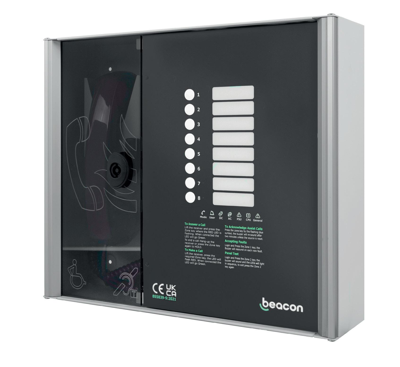
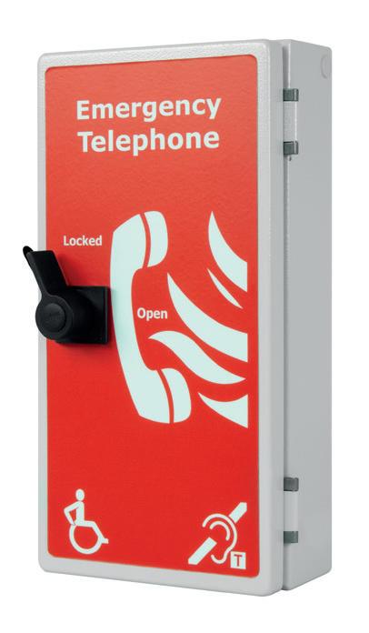
84 A look at the specific recommendation for refuge areas to be provided with an emergency voice communication (EVC) system
102 Where did halogen-free flame retardant cables come from and why are they important?
104 Why you need to apply due diligence when installing cables in thin walls and/or partitions
106 How to improve sales conversions in your business
108 ‘Codebreaking’ the latest on-site finds from electricians on the job
110 What is the best way to deal with employee bereavement?
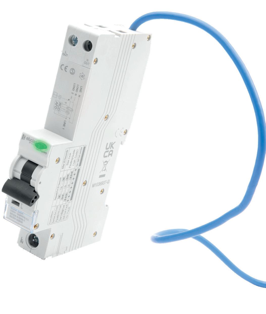
112 Delving deeper into the technology behind AFDDs
114 Taking a closer look at selectivity requirements for distribution circuits
116 How does maximum demand work and why is it important?


W O R K T H R O U G H E A C H S E C T I O N A N D E A R N 6
C P D C R E D I T s ( o r 6 h o u r s o f l e a r n i n g )
T O WA R D S YO U R P R O F E S S I O N A L R E C O R D !
continuing professional development (CPD) can be broadly defined as any type of learning you undertake which increases your knowledge, understanding and experiences of a subject area or role

To help professionals to better document and prove this process, the CPD Book contains content and articles that have been checked, verified and accredited by a third-party specialist organisation
Collectively, the content within this specially designed publication has been deemed worthy of 6 CPD credits, or 6 hours’ worth of CPD, with each individual section providing 1 credit, or 1 hours’ worth of CPD.
Once this content has been consumed, readers will have the
opportunity to scan a QR code which will provide a bespoke, downloadable certificate that can be used as part of a professional’s ongoing CPD record
THE CONTENT WITHIN EACH SECTION!
A large element of CPD involves self-certification and relies on professionals being honest about what they have actually read, consumed and digested A QR code has been placed with the final article in each of the six learning sections within this publication and ONLY once you have read ALL of the articles within each section, should you then scan the code to receive your bespoke certificate
By skipping any of these steps, you’re not just cheating the system, but yourself and your fellow professionals at the same time!
CERTIFICATE IN FIVE STEPS
1. Read ALL of the content and articles included within the six sections
2. Find the QR code with the last article in each section and scan
3 Enter your email address
4. Fill out your details on the contact form
5. Download your certificate for use as part of your annual CPD record

PREVIOUS USERS – ACCESS YOUR CPD CERTIFICATE IN FOUR STEPS
1. Read ALL of the content and articles included within the six sections
2. Find the QR code with the last article in each section and scan
3. Enter your name and email address.
4. Download your certificate for use as part of your annual CPD record
All certificates are valid for one year from the issue date If you’re having any issues with downloading your certificate or using the system, please email us at: pe@hamerville.co.uk
to know to stay ahead of the ‘prosumer’ curve.
“A building that is an active component of the energy network and that moves beyond a unidirectional flow of energy into the building to that of bi-directional flow ” BS7671: Part 8 Chapter 82: The Energy Prosumer
As the UK attempts to use less fossil fuel and move towards a Net Zero Carbon 2050, significant new demands will be placed on our existing energy systems Many more of us will become prosumers This will have three important implications for the electrical and wider electrotechnical sector:
1. More business: prosumer activity is set to provide huge opportunities for retrofitting existing buildings and installation in new buildings
2. Attracting talent: as one of the sectors at the centre of a building and infrastructure Net Zero Carbon 2050, the demand for modern technology and techniques will help to drive recruitment
3. Trusted experts: the electrical services sector will become increasingly relevant to policy conversations about
the UK’s energy direction and future, and to clients, making it a principal agent of positive change
Prosumerism: why now?

“Energy generated from renewable energy accounted for over 43 per cent of the energy provided to the electricity grid in 2020 ” BS 7671 (March 22): Part 8, Chapter 82 The Energy Prosumer
The UK regularly generates more electrical energy from renewables Renewables' share of total generation was 42 8 per cent at the end of 2021, up by 2.1 per cent on 2020. This trend is set to increase However, growing reliance on renewables raises issues such as

consistency of energy supply.
To ensure a sufficiently consistent UK energy supply, the ECA has actively lobbied government and industry stakeholders in three key areas:
1. Generation
2. Storage
3 Energy efficiency
In reality, we need a combination of effective measures across these three areas But even focusing on points two and three improved storage and energy efficiency could save the UK economy £30-£70 billion according to BEIS’s ‘Transitioning to a net Zero energy
system: Smart Systems and Flexibility Plan 2021’ (view this at: bit ly/3xLuonF)
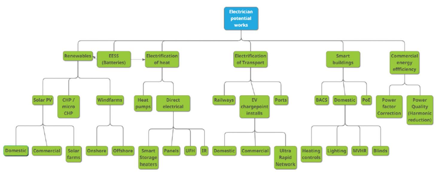
The ECA Guidance Note ‘Planning for a Green Pivot v 1 2’ identifies many opportunities for low-carbon electrotechnical activity, outlined in the diagram on page 36
Looking at three of these opportunities in more detail:
i) Transport: building the domestic and commercial infrastructure
Electric vehicles (EV) have already entered an early exponential growth phase In 2015, just over 1 per cent of new vehicles registered also had a plug, compared with almost 19 per cent in 2022 (according to the Society of Motor Manufacturers and Traders). Key factors such as current fuel prices and the none-too-distant 2030 ban on the sale of new internal combustion engine (ICE) vehicles will reinforce this trend and increase the need for Electric Vehicle Charge Point (EVCP) installation and maintenance for both domestic and commercial use
ii) Heating: making homes carbon-efficient
As part of the Boiler Upgrade Scheme,
a £450m government grant came into force in May 2022, providing £5,000 for households to install air source heat pumps (ASHP)
Furthermore, with no VAT on heat pumps for the next five years, support for this sector looks set to continue, so electrical contractors may decide to invest in training and certification on the basis of improved predictability
As the carbon intensity of grid electricity falls, for new or well-insulated houses, the direct electrification of heating – such as underfloor heating, infra-red heaters, or ‘smart’ storage heaters – may become more and more worthwhile following forthcoming changes to the Building Regulations (which have historically penalised electric heating)
On a domestic scale, solar PV is once again back in vogue With high energy prices set to continue, this solution is growing in popularity for both retrofit and new-build projects. The combination of the Green Homes Grant and Building Integrated PVs (BIPV) has boosted the appeal of solar PV installations for new builds especially

Electrical Energy Storage Systems (EESS) offer a whole new level of flexibility and convenience, allowing users to buy energy from the grid when usage and prices are low, and sell it back at peak times As EVs become ubiquitous, Vehicle to Grid (V2G) charging will become an integrated feature of many homes, making use of the EV’s significant electric battery
To do the work needed to meet our Net Carbon Zero targets, electricians will need to add new skills to their arsenal This means training and certification will be incredibly important, both for businesses and qualified electricians looking to expand their capabilities It will also be vital for the career progression of any new and prospective industry entrants
Electrical energy storage system (EESS), Electric Vehicle Charge Point (EVCP) and heat pump training and Building Automation and Control Systems (BACS) are areas where technicians can expand their skillset right now.
For installers looking to work within funded schemes, MCS certification is required In some circumstances, they will need PAS 2030 when installing under a PAS 2035 Retrofit program
At the outset of this article, I mentioned the recent addition of Chapter 82 to The Wiring Regulations It highlights how the electrical systems within our buildings will need to interact with a smart and decarbonised energy grid. It introduces a couple of new terms: Energy Prosumer and Prosumer Electrical Installation (PEI)
To understand fully connected systems such as PEIs, electricians will need to understand how the various elements on-site generation, energy storage, heating systems, EV charge points, to name a few – fit together, both with each other and with other trades Incorrect specification or installation could lead to expensive mistakes down the line, when a whole building doesn’t work as intended
The electrotechnical sector has a vital role to play in shaping the UK’s decarbonisation given our understanding of the technologies involved and the need for qualified and competent installers to deliver on the government’s objectives
In late March 2022, the IET Wiring Regulations (BS7671 – 18th Edition) were amended to address amongst other things energy efficiency and prosumer

installations, formally introducing us to the terms ‘Energy Prosumer’ and ‘Prosumer’s Electrical Installation (PEI)’
ECA has produced guidance in this emerging area, including the Chapter 82 Energy Prosumer Guide. Additionally, ECA’s ‘Planning for a Green Pivot v1.2’ document covers an array of Net Zero Carbon 2050 opportunities for ECA Members, in particular guidance on support schemes, training and accreditation
The terms, Energy Prosumer, and Prosumers Electrical Installation (PEI) are set to become more common as the industry gears up for Net Zero Carbon 2050
As one of the industries at the forefront of sustainability and Net Zero, we are faced with a unique and unprecedented set of opportunities When these sustainable technologies can be designed to work together the effects can be ground-breaking
However, ongoing training and accreditation will be vital to ensure that installations are carried out in a timely manner (to satisfy government objectives), effectively (to satisfy consumer needs), and efficiently (to satisfy Net Zero Carbon 2050 targets)
The energy prosumer model offers significant opportunities, and a range of new challenges. To work efficiently and effectively, solar panels, batteries, EV chargers and heat pumps will need to work in harmony This means they will need to work as a prosumer system, and not just as individual product types It is therefore vital that designers and installers have sufficient training and skills to make this possible, and to make sure that the technologies are configured to work collectively
Ultimately, customers will become much more aware of their own energy use and production as we move beyond the status quo of taking grid supply, and its flat charges, for granted Load-shifting will become a prominent part of prosumer installations, especially for heating and EV charging A combination of rising or, at best, highly variable energy prices, plus new legislation and standards are shaping the future of UK grid supply and interactions
Below is just one example of what installers will increasingly encounter as we begin to engage with the prosumer environment:
Where a building is expected to run independently of the grid (in what is called ‘island mode’), specific earthing conditions and controls should be applied In addition, checks will be needed to ensure that the local system will be running in-phase with the grid prior to grid re-connection Additionally, installers will need to consider dedicated circuits when running in island mode
o f f l e x i b i l i t y.
The microgrid controller at the heart of this project uses a web-based user interface that communicates real-time energy use, savings and CO2 emissions data This microgrid controller also links directly to third-party sites, such as weather forecasts, to decide whether/when to deplete or charge the batteries
For example, if the user has specified cash saving, then weather forecasting data is combined with energy tariff predictions to decide when to use power, when to store it, and when to sell it back to the grid
Sustainable technologies used:
● 135kWp rooftop solar PV system
● 6kWp carport solar PV + 5 EV charge points
● 216kWh battery storage in bespoke ISO container
● Schneider Microgrid Controller
“It is fantastic to be able to work on this unique, innovative project, implementing new systems and technologies in a way that we hope will be a beacon to future developments The innovations included in the scheme fit perfectly with the University’s aims to enhance its sustainability and reduce its carbon footprint by generating its own renewable power ”
Chris Phillips, Contracts Manager, RDM
I have recently been asked to look at a fire alarm in a building, which is a category BS 5839-1:2017 L1 system. Correct me if I am wrong, but is an L1 supposed to have detectors everywhere? I have looked at the system, and there are detectors missing from cupboards, a toilet and, worse still, a stairway lobby. Also, are you a real Doctor?
Thank you for your Question, Mr S Ives (Fire Risk Assessor)

If you look in Clause 8 2 f of British Standard 5839-1:2017 it states, certain areas may be classed as areas of low risk
The standard states in clause 8 2 f, in categories L1 and P1, automatic system detectors should be installed in all rooms of the premises; however, the following rooms may not be protected if they are at low risk of a fire occurring:
● Bathrooms/shower rooms and toilets

● Toilet lobbies and stair lobbies
● Small cupboards less than 1 m2
There are a couple of notes within clause note 8 that state that in some buildings, such as shopping centres and hospitals, toilets may not be low risk because of the risk of arson
Note 9 states that a riser cupboard that has a fire-stopped floor and ceiling may be considered a cupboard. Note 10 states that detection may be excluded from the same such areas in L2, L3, and L4 category systems
Now here's the bit that does not sit comfortably with me: this clause states: ‘these areas need not be protected if they are of low fire risk’ (see 3 33) This means that for a fire alarm engineer to make this decision, they are deciding that the areas are low risk and then signing a document accordingly
When you look at Clause: 3 33, Low-risk areas or rooms, it states: ‘a room or area that contains very little or no combustible substance and has no ignition sources, which any foreseeable fire is unlikely to spread to cause a threat to escape by occupants or damage to property’.
To me, it is far better for a qualified, competent fire risk assessor to make that decision
Stair lobbies are one of the areas of low risk that I have highlighted for change in the next update of the standard as I do not feel these should ever be classed as an area of low risk
Going back to the original question, it would appear that the designer deemed the areas you
Shower rooms and bathrooms are fairly easy to judge However, pay close attention to the cupboards because what is contained in the cupboard may make it high risk –many will contain a consumer unit or a server, or even flammable liquids; all of these would not be of low risk
Now on to the second part of your question: am I a real Doctor?
The short answer is ‘yes’ I was given an honouree Doctorate in 2014 for the work that I did to help a university with a fire detection system dissertation It does say ‘Doctor’ on my driving licence etc but I’ve not really used the title as its honouree I have just passed a full PhD, however, and am now a fully qualified Doctor. As of earlier this year, I am also now a Professor
DO YOU HAVE A QUESTION YOU'D LIKE ANSWERED?
EMAIL YOUR QUERIES TO: TOM@ZZEUS.ORG.UK
GET


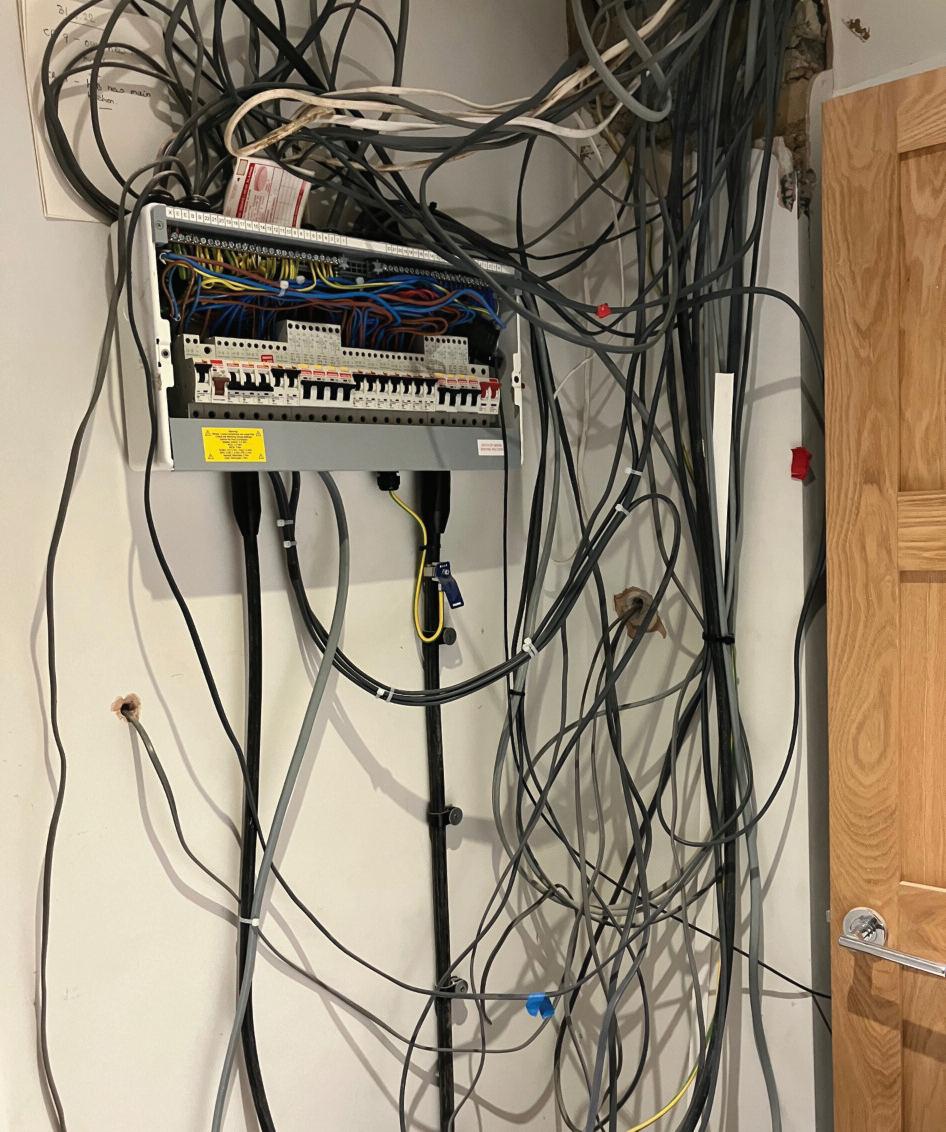
Some things just never seem to change, which is ver y frustrating. There are so many defects here that it's tough to k now where to star t, so I'll tr y and group the various issues together where I can:

1. Terminations and single insulation not taken into an enclosure are a problem as there is no adequate mechanical protection There are a few of those issues in the photo.
2. Terminations not adequately suppor ted may cause strain on them, leading to loose connections and possible arc faults and fires This would explain the intermittent flickering operation repor ted by the Client.
3. Cpc is not taken to each accessor y and point in a circuit, which means there is no shock protection after the first accessor y We can see where the cpc has been intentionally cut and left out of the way on the 3- core flex
B Single insulation and conductor
enclosure
4. The termination of the cpcs in some of the flat twin and ear th cables is not adequate Twisting cpcs together is neither a reliable method to ensure adequate termination nor will it aid in periodic inspection and maintenance.
5. I can’t see from the photo if there is any access to live par ts where the terminal connectors are used A couple of them seem to have multiple conductors in them, which may or may not give rise to access to live par ts

The shameful thing here is that the work seems to have been a recent install, which means the low level of sk ills shown is likely to be found in other installations by the same installer This type of work manship is only ever going to receive an unsatisfactor y result on an EICR
not taken into an
526.6

134.1.1, 526.1, 526.3, 526.5
134.1.1, 416.2 FI C2 C2 C2 C2
Need help with cracking those all-impor tant EICR codes? Ever y month the technical team at NAPIT will be studying your latest ‘Caught on Camera’ photos and offering advice on the next steps, should you find a similar installation. If you want the team at NAPIT to help crack your codes then send your pic tures through to us at: pe@hamer ville.co.uk

DAYS
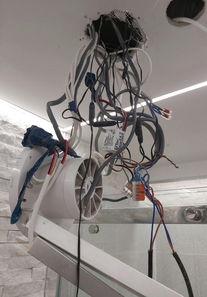
Wow, just wow! A work in progress is one thing, but this is pretty astounding
From the top, the lid being left off and not even in sight to be replaced is leaving this installation dangerous, with access to live par ts before we even star t Even though this isn’t strictly an EICR, the Client has called someone in to give an opinion which can be seen to be an EICR of sor ts
The unacceptable cable management is next up and is a pretty easy fix that could have been avoided from the star t with some well-placed trunk ing I’m not quite sure what the cable connected through the CU front opening is doing, but it will need to be re -routed, as the cover won’t fit with it there!
The state of the cables inside the CU is difficult to see from the photo, so I’ll leave that out of the equation I will comment on the SWA bottom right, though, as it seems to have a BS 951 clamp on it, with a conductor then entering the metal CU in a different opening to the SWA This could have eddy current issues with high loadings; I’m not sure why that ’s been done, as the SWA gland would have adequately and acceptably transferred any cpc requirements to the CU
The BS 591 clamp is also not designed to be used in this way, as adequate torque to the armouring cannot be confirmed, and by doing this, there is a risk that the SWA cores can be crushed and damaged
C


This is a totally unacceptable and dangerous installation that could easily be rectified by a sk illed and competent installer
The Observations, Regulation infringements and Codes applicable to this observation would be:


A cable appears to prevent the CU lid from being tted, causing access to live parts 134.1.1,

No adequate cable containment, the strain on terminations134.1.1, 522.8.5
SWA has a BS 951 clamp used to direct a cpc to the CU, as well as its own SWA gland, also causing a potential eddy current issue on high load with conductors entering a metal enclosure through di erent openings
134.1.1,
The 18th Edition Codebreakers publication is priced at £17.99 (members) or £19.99 (non-members). Hard copies and digital issues are available.


* Prices exclude VAT, postage and packaging

CLIVE HAMILTON: I WAS ASKED TO VISIT A SITE WHICH WAS WIP ( WORK IN PROGRESS) AND THE SPARK WAS STRUGGLING! BEAR IN MIND THE ‘OTHER’ SPARK WASN’ T ON SITE AND THIS WAS LIVE WITH THE COVER NOWHERE TO BE SEEN – NOTHING SURPRISES ME ANYMORE! IT SEEMS THERE ARE FEWER SPARKS TRYING TO FOLLOW GOOD PRAC TICE AND THE REGULATIONS THESE

Many commercial and industrial installations employ networking cables for their main infrastructure of Ethernet networks, enabling a permanent and reliable link for communication between items of equipment such as workstation computers, printers and network servers
However, some devices, such as those used to control office lighting, work on a connected bus system operated through a software interface including, typically, multi-pair cables having a screened data pair and unscreened power pair Within the home, smart devices such as entertainment equipment, lighting and heating control systems often require a network connection. This connection, typically based on a local area network (LAN), allows such devices to:
● access internet-based data sources and services; to retrieve the latest information such as the weather conditions for enhance energy efficiency,
● give the user greater control and monitoring of connected devices while away from the home, to further improve energy performance and/or provide increased security property monitoring.
In larger premises, the use of access points (AP) for expansion of the wireless network may be an option, although these devices typically require a separate network cable, such as a twisted pair cable, which allows for data and power to be transmitted within the same cable.
This is often referred to as Power over Ethernet (PoE)
A l t h o u g h m a n y d e v i c e s c a n c o n n e c t w i r e l e s s l y t o a n e t w o r k , s u c h c o n n e c t i o n s a r e g e n e r a l l y l i m i t e d i n r a n g e, s u s c e p t i b l e t o s e c u r i t y b r e a c h e s a n d c a n s u f f e r f r o m i n t e r f e r e n c e d u e t o e x t e r n a l i n f l u e n c e s , l e a d i n g t o p o o r s i g n a l q u a l i t y o r l o s s o f s i g n a l a n d c o n s e q u e n t l y, f a i l u r e o f e q u i p m e n t
For this reason, the installation of dedicated data network cables may be a favourable option In addition to improving the reliability of connected devices, having a direct link to the LAN also permits larger amounts of data to be transferred at increased speed whilst reducing the latency1 between input and output devices
Twisted pair data cable
N e t w o r k i n g d a t a c a b l e s a r e c o m m o n l y m a d e u p o f f o u r t w i s t e d p a i r s o f c o p p e r c o n d u c t o r s , a l t h o u g h o t h e r v a r i a n t s o f c a b l e s a r e a v a i l a b l e ( s e e F i g 2 ) . T h e t w i s t e d p a i r s a r e t y p i c a l l y u s e d f o r c a r r y i n g d a t a s i g n a l s , a d i g i t a l p u l s e o r t h e v a r i a t i o n s i n v o l t a g e b e t w e e n ( T X + a n d T X- ) a n d ( R X + a n d R X- ) c o n d u c t o r s 2 Ty p i c a l l y, n o t a l l t h e t w i s t e d p a i r s w i t h i n
The team at NICEIC provide guidance for the contractor on the installation of twisted pair network cables to BS ISO / IEC 11801 and BS EN 50173 series, and compliance with BS 7671 requirements.

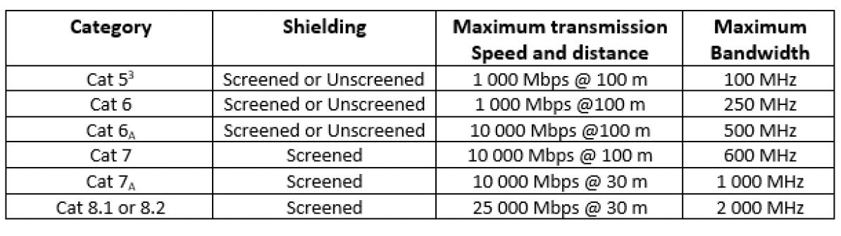
t h e c a b l e a r e u s e d f o r t h e t r a n s m i s s i o n o f d a t a T h e p e r f o r m a n c e a n d a b i l i t y o f a c a b l e t o t r a n s m i t l a r g e a m o u n t s o f d a t a f o r a p a r t i c u l a r a p p l i c a t i o n d e p e n d s m o s t l y u p o n t h e c a b l e’s g r a d e o f c o n s t r u c t i o n T h e s e g r a d e s a r e g e n e r a l l y c a t e g o r i s e d ( C a t e g o r y 5 - C a t e g o r y 8 2 ) a n d a r e u s e d t o i d e n t i f y t h e a m o u n t o f d a t a t h e c a b l e c a n c a r r y, a m e a s u r e o f h i g h a n d l o w b a n d w i d t h , a n d t h e s p e e d a t w h i c h t h e d a t a c a n b e t r a n s m i t t e d f r o m i t s s o u r c e t o o u t p u t d e v i c e ( t r a n s m i s s i o n s p e e d ) ( s e e Ta b l e 1 )
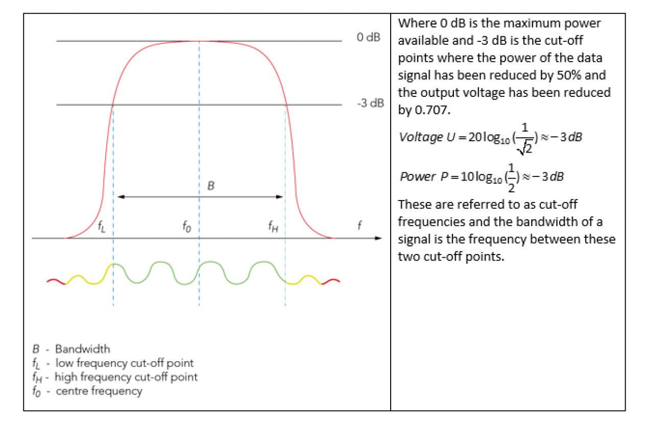
The bandwidth is the ability of a cable to carry a signal ranging across upper and lower bands of frequency over a period of time For example, a Category 5 cable having a maximum bandwidth of 100 MHz would be able to process a signal between point’s f L and f H on a frequency response curve, as shown by Fig 1
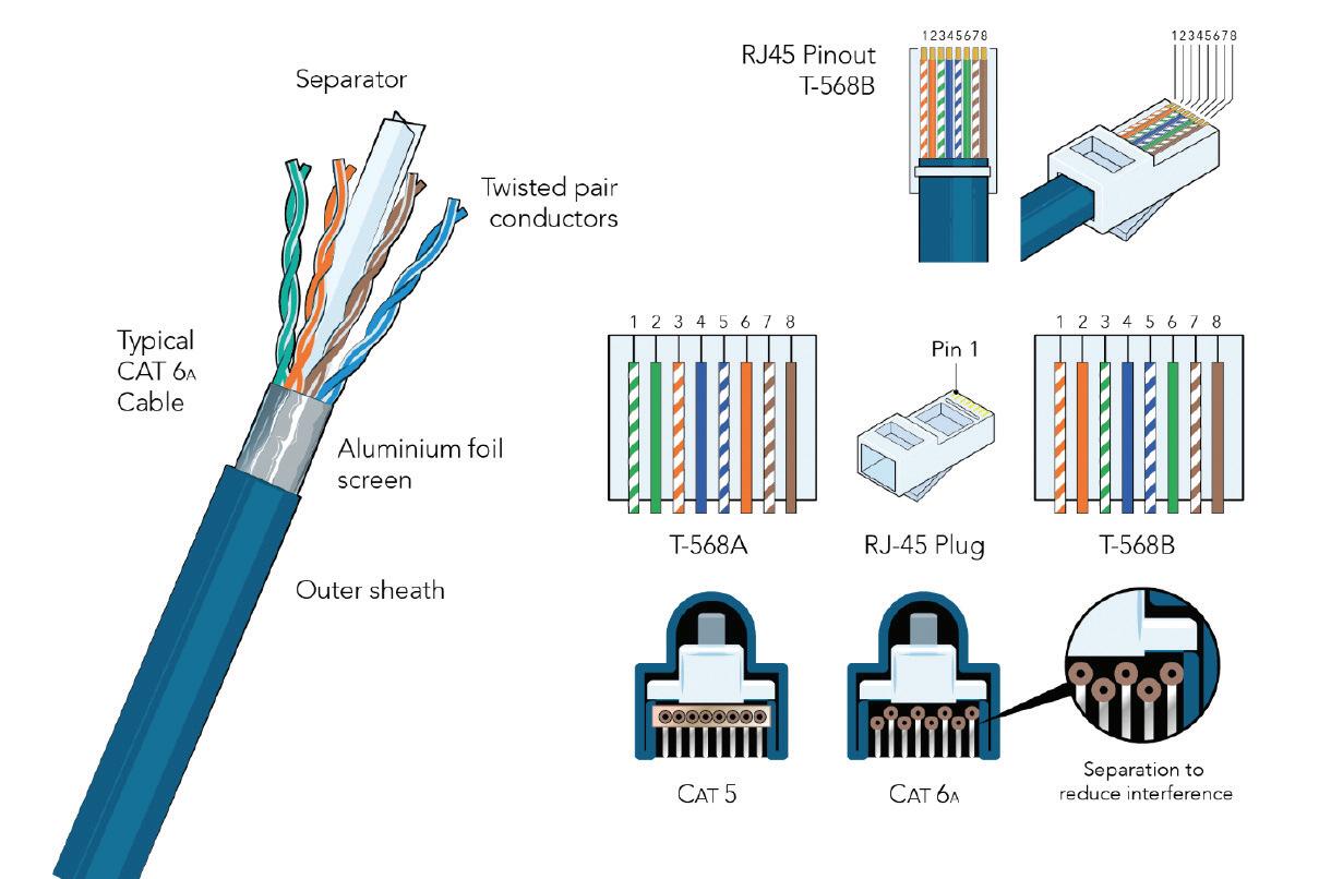
The method of construction varies between the Categories and relates to the performance of the cable For example, a screened Category 6A cable as shown in
Fig 2, is capable of transferring greater amounts of data per second in comparison to that of an unscreened Category 5 cable. This is due to the improved construction, which includes:
● An outer sheath; this may vary between manufacturers but mostly consists of PVC, polyethylene or low smoke halogen (LSZH) insulation3
● Interior separation used for mitigating the unwanted coupling of adjacent conductors and preventing induced noise (crosstalk) transference between each twisted pair of conductors
● Inner aluminium foil screen prevents external noise (alien crosstalk4) from disrupting the transmitted signal
● C onductors, vary in cross-sectional area (csa) between categories
Typically for Category 6A the csa is
0 258 mm2 solid copper, generally covered with high density polyethylene insulation, arranged in four twisted pairs
● The twisting arrangement of conductors varies in pitch between the pairs of conductors within the cable and is measured in twists per inch (TPI) This helps to reduce the internal crosstalk or electromagnetic interference between pairs of conductors, allowing for pure signal distribution with less error
The TPI is typically increased between the pairs of conductors in a Category 6A cable compared with that of a Category 5 Cables having stranded copper conductors provide greater flexibility and would typically be used for patch cables or for final connections to portable devices
The connection of electronic equipment is referenced in the IEC 60603-7 series and relates to the interface of Category cables and the termination of conductors, as shown in Fig 2 There are two standards for the connection of RJ-45 terminations, these include T-568A and T-568B (defined in the US standard ANSI/TIA/EIA-568 2-D), which relate to the order of terminations of conductors within that standard
It is critical to have correct and adequate terminations at both ends of the cable. Any poor termination will reduce signal strength, cause a loss or noise in the transmitted signal creating distortion and data error
The PoE applications use either two or four pairs to deliver power to terminal devices; power can be transmitted over data conductors
Other applications may include the distribution of a DC power supply through a device such as an Ethernet switch, used to connect equipment such as lighting controllers, IP cameras and wireless access points over the same data network cable
The requirements of BS 7671 are applicable to the installation of network data cables within a building – refer to (110 1 2 indent (vi))
Network cables are often distributed throughout the fabric of a building, usually from a central location, which makes it possible for them to be in contact with, or close proximity to, other cables having different operating voltages
To minimise the risk of interference between cables of different voltage levels:
● Band I and Band II circuits shall not be contained in the same wiring system as circuits having a nominal voltage exceeding that of low voltage, and
● Band I and Band II circuits shall not be contained within the same wiring system, unless one or more of the conditions in indents (i) to (iv) of Regulation 528.1 are met.
Where network cables of Band I are installed in a duct or shared void underground, and/or cross with cables of Band II, segregation should be provided to achieve a minimum separation of 100 mm Where this is not practical, mechanical protection shall be provided (528.2).
Similarly, network cables are often terminated within patch panels or media cabinets enabling peripheral equipment such as Ethernet switches, routers and entertainment equipment to be contained within one location However, mixed voltages are likely to be grouped within the same assembly in which segregation will be required (515 2)
It is important to recognise, that where necessary, adequate support must be provided for Band I networking cables to prevent their premature collapse in the event of a fire (521.10.202). This may be achieved in a number of ways including:
● metallic clips inside or outside of plastic trunking
● metallic saddles holding plastic conduits
● metallic clips on wall-mounted cables.
Cables installed in steel trunking/conduits and on top of cable tray/ladder rack are not considered to be an entanglement risk Similarly, additional support is not required for cables installed in floors, above ceilings or behind plasterboard. Furthermore, the methods used for sealing low voltage cable penetrations within a building structure also apply where data networking cables are installed Such sealing arrangements are a fundamental requirement of the Building Regulations in England, Wales, Scotland and Northern Ireland, in addition to the requirements of Regulation Group 527 2 of BS 7671
Where it is necessary to install network data cables for equipment within a building, installers need to be mindful of the suitability of a cable for a particular application; reference should always be made to manufacturer’s recommendations

In addition, where such types of cable are likely to be installed in proximity to cables of mixed voltages, creating a potential for interference and signal error, segregation shall be provided
The need to provide adequate support for Band I networking cables for the prevention of premature collapse in the event of a fire must also be considered
1 The term latency describes the time delay of a data signal having been sent from a source and the receiving device acting upon the signal received
2. TX+ and TX- are the pair used for transmission whilst RX+ and RX- are the receiving signal pair
3 Manufacturers often reference a cable sheath having (LSZH), although Construction Product Regulations (CPR) specify a particular code highlighting product conformity for example BS EN 50399 B2ca s1a d1 a1
4. Alien crosstalk is referenced in BS ISO / IEC 11801 series, which relates to the induction electromagnetic interference from neighbouring cables
Owning a business takes you through the highest of highs and the lowest of lows You’re taking huge personal risk on a daily basis and on top of that you’re responsible for the actions of everyone in your company Of course, there can be huge rewards to reap, but the long and short of it is that it starts and ends with you, the way you build and lead your business, and you can always improve on that.
This year could be another difficult one for businesses, but here are five tips that can help you to be a better business manager:

1. Put structure, systems and policies in place
Without good structure, systems and policies your business has little chance to
grow A big reason trade business owners ‘burn out’ is that it’s easy to fall prey to the false perception that you need to be everywhere at once: quotes and invoices can’t be sent out without you checking over them, the job can’t be finished without you looking over it, and so on What you should be doing is building a business that works for you, not the other way around The way to do this is by setting up policies, systems and processes that are black and white and leave little room for interpretation. These include your materials management policy, your customer service promise, your company values etc If anything goes wrong in a business it’s usually because there’s an issue with the systems or the structure or procedure that the business is built on, and that’s what needs your attention.
The first step here is hiring the right people with the right attitude If you’re hiring individuals who are not up to scratch because they were a bit cheaper and the rest of your team have to pick up the slack, it hurts the productivity of the team as a whole and they will probably resent you for it
The next step is to onboard them properly and make sure they understand your systems, processes and values. For instance, if one of them turns up on a job and he/she hasn’t really slept but didn’t know that your company values are safety and high-performance, is that your fault or theirs? The answer is probably both
The last step is to train them Training is a great way to show that you care about employees’ mental and professional
2 Invest in your teamwellbeing on a personal level and also to show that you’re going out of your way to help them grow Moreover, if you don’t train your people, you’re never going to get the best out of them.
If you doubt yourself sometimes and you’re not overly confident about running or managing your business, here’s a tip: practically no one is. Most tradespeople don’t have a business background and even those who do are never really 100% sure things are going to work out But if your default is to doubt things will work, you can be sure they won’t pan out
If you don’t believe in yourself and your business, you can bet your bottom dollar you’ll see it affect your staff, your productivity and your profitability Having said that, everyone goes through periods of self-doubt, it’s in our nature So if you are feeling down on the company, don’t let your staff see it and definitely don’t take it out on them. Talk to your friends or
other business owners who’ve been through the same things You’ll be blown away by how many other people have been through the same problems and found a way around it.

This is an easy one If someone makes a grave error in your business, you have to be ok with that Delegation is an essential part of growing your business and other people are rarely going to do things exactly the way you want it But, if someone slips up again and again, the consequences are on you It sounds tough but if the process is broken, fix it and if the person can’t be helped, let them go.
Most business owners will hate this one, because most of us know it’s something we should be doing and it will never be more relevant than it is today. Too often, we shuffle a Profit/Loss or cashflow
forecast to the back of our minds and convince ourselves that we have more important things to do If we’re being honest, most of us are just a bit scared to look or don’t know what to look at.
The reality is nothing is more empowering for a business leader than getting a firm grip on your finances because it gives you the ability to make strategic decisions for your company If you’re a little bit in the dark on where your numbers are, download a free cashflow forecast template from the internet and fill it out
In summary, you don’t need to be the best at everything to be a better leader The most effective leaders largely achieve results because of the people and structures they place around them. But you do need to look after your team, be someone they can respect and, more than anything, you need to back yourself


What have we been missing?
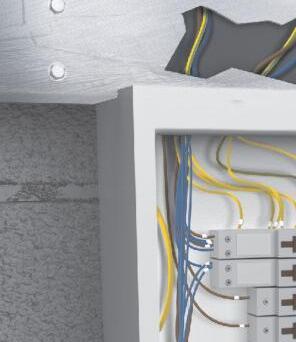
Often overlooked is the importance we should place on enclosures to ensure any conductors and their respective terminations are adequately protected from mechanical damage and accidental contact, especially from ordinary persons
The most common problem we see when we look at installations, either new or existing, are single insulated cables not taken into an adequate enclosure
Whether the exposed single insulation is the result of 6491X cable improperly used, from missing trunking lids (which is very common), or from a sheathed cable with the sheath removed, exposing single insulated cables, such as 6242Y flat twin and earth, 6945X armoured or 6181Y meter tails, the problem is the same.
Why is this a problem?
Single insulation does not provide any mechanical protection, which means it’s susceptible to the rigours and abuses of everyday life. I say abuses because the seriousness of injury from electricity is very much maligned, and there is an assumption that the cable will protect you from the electricity flowing through it against all things – from walking on it to hanging things off it
As single insulation does not possess any mechanical protection properties, by
its design, we need to ensure it’s protected in some way, and that’s where enclosures come in and why they’re so important BS 7671 is very specific when it mentions and defines an enclosure.
According to Part 2 Definitions, an enclosure is:
‘A part providing protection of equipment against certain external influences and in any direction providing basic protection.’
That’s not enough on its own, though, so greater clarity is given in Regulation 526 8, which in turn refers to 526 5, requiring single insulation to be treated as any termination or connection in a conductor. In requesting this, the single insulation must be taken into either:
● An accessory complying with a suitable product standard
● An equipment enclosure complying with an appropriate product standard
● An enclosure partially formed or completed with non-combustible building materials, or
● A combination of two or more of the above
What’s the solution?
A reason for leaving single insulation
outside of an enclosure that we often hear is that there isn’t room in the given enclosure to fit the cables and terminate them adequately As we look at enclosures, we can agree that this is an issue in some cases, but there certainly is no excuse to do it, as there are devices to help overcome this
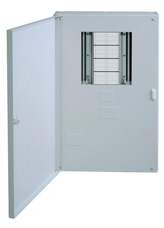
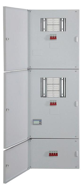
Where there isn’t room in a manufacturer’s enclosure, distribution board (DB) or consumer unit (CU) to adequately encase the single insulated cables, extension and spreader boxes can be used These items provide an extra section of enclosure that can house single insulated cables to allow a tidy and adequate connection inside the main enclosure
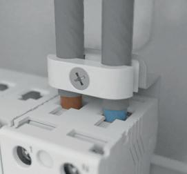
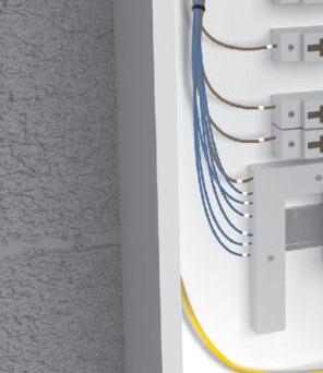
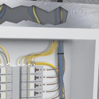
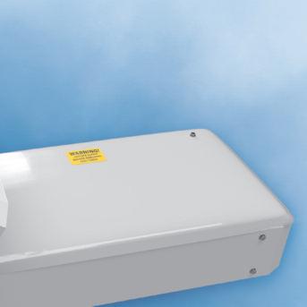
Fig 1 and Fig 2 illustrate the two main types of spreader boxes
Individual entry spreader boxes are designed to allow the sheath of larger cables to be stripped back so that the single insulated conductor can enter the enclosure This facilitates good termination of the conductors without tight radiuses or undue stress on the terminations


Multi-cable spreader boxes, or extension boxes as they are sometimes called, effectively extend the enclosure This allows the sheaths of multiple cables to be stripped back so that the enclosure, generally a CU, is free from masses of cable entries that can cause stress on the eventual terminations and from the issues associated with the close confines of switchgear
Although most of these pieces of equipment are designed to be used with a specific manufacturer’s enclosure, there are alternatives
Where a consumer unit, especially in a domestic setting, requires multiple armoured cables, simple trunking adequately installed can do the job just as effectively
Providing the correct lids and end plates are used, different trunking sizes can be re-purposed to provide a tidy interface between multiple cables and a CU/DB, especially for CU/DB changes, where space and existing cable lengths are challenging

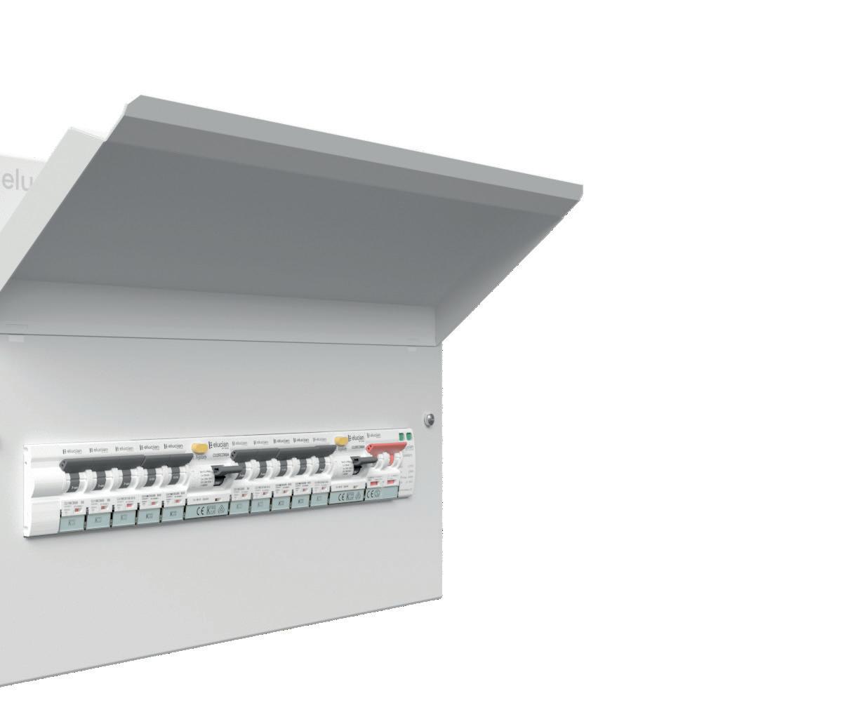
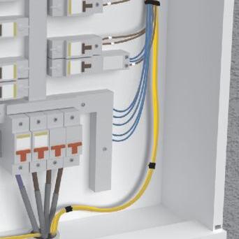
If we look at Fig 3, we can see that a CU/DB has been installed using a section of 100 x 100 mm metallic trunking. Fitted neatly along the top edge of the CU/DB, it


provides a useful interface to terminate several armoured cables

This, in turn, allows the single insulated conductors of these types of cables to enter the CU neatly without causing any obstructions In the same way, flat twin and earth cables have also been installed this way, which stops the sheathes from cluttering the inside of the CU/DB
The following are some useful outcomes of this type of design for an installation practice:


● Removes unnecessary clutter from the CU/DB or enclosure
● Reduces stress on terminations and conductors

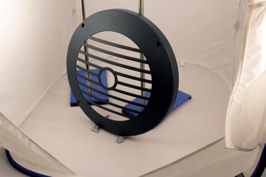
● Promotes air circulation and cooling for


terminations, conductors and devices within the main enclosure
● Allows clear identification and access for future periodic inspections
Although the example in Fig 3 uses metallic trunking as a spreader, because of the extra stress incurred by the armoured cable glands, this does not preclude the use of plastic trunking

Generally, plastic trunking is more than acceptable for utilisation in this way, especially where flat-sheathed cables, such as flat twin and earth used in domestic and less complex installations, are the only cables used in the installation


Using plastic trunking in this way isn’t a problem in domestic installations with metallic CUs as the trunking does not contain switchgear, and as such, it is not required to be of metallic construction, as is the CU


Something to remember, however, is that whenever a site-manufactured spreader/extension box is used in this way, it must be fit for purpose and include the correctly fitted end plates and trunking lid The key to a safe installation lies in its design. Without a solid understanding of design principles, we run the risk of falling short of the most basic requirements

Since the release of the 18th Edition there has been an increase in the use of Surge Protection Devices, and this is only growing with the additional requirements in Amendment 2 As always with a new subject matter, there are a few frequently asked questions that I hope to cover in this article:

QWill an SPD need replacing after every surge?
No, an SPD is designed to take multiple surges and internally reset after each overvoltage An SPD will only need changing at the end of its life (the warranty is manufacturer dependent) and this will be shown in the status indication on the front of the unit
QWhen do I need to use a Type 1?
With the increase in availability of consumer units with the SPD already installed, it is becoming more of a consideration as to whether this is the correct device A Type 1 will be needed in a domestic installation, if the property is supplied via an overhead cable. Outside of domestic installations, a Type 1 device
will also be required if the structure has an external lightning protection system
QWhy do some manufacturers need an MCB (Miniature Circuit Breaker) before the SPD?
According to BS7671, all SPDs shall be protected from overcurrent, which can be done through the use of an MCB or internal fuse. As a company, we specify the use of MCBs with all of our devices The MCB will provide a back-up in case of a failure within the SPD, while also protecting the cable and giving a point of isolation for the SPD
QHow do I measure the cable lengths to ensure I meet the BS7671 requirements?
If the SPD is installed within the consumer unit, cable lengths will automatically be suitable When installing outside of a consumer unit, you must ensure that all cables combined are less than 1m in length. Length A will be from where you take your live supply to the MCB (this is ‘0’ if the MCB is on the busbar), Length B is from the MCB to the SPD and Length C is from the SPD to the closest earth point (not the MET) For a more detailed explanation of this, please look at the installation guide available on our website.
QWill an SPD installed in the consumer unit protect the whole domestic property?
An SPD in the consumer unit will massively reduce the risk of any internal damage within the electrical installation from overvoltage coming from the mains supply Obviously, there are other routes of entry into the electrical system, via aerials, telephone lines or any external cables, but there is no requirement in BS7671 to protect these routes
QDo I need to install Type 3 devices in a domestic installation?
There is no requirement to use Type 3 devices. The Type 2 on the consumer unit provides an enhanced level of voltage protection for the installation Type 3 devices would only be used in specific specialist circumstances
If you have any questions that I haven’t covered in this article, or would like any specific help with a project or installation, please contact me directly at: kirsty@surgedevices.co.uk


Every electrician with experience of working on a busy site knows how it feels to take responsibility for the other professionals around them When you are dealing with live electricity there’s no room for calculated risks and educated guesses.

The only way you can ensure your and your colleagues’ safety is by adopting adequate isolation procedures
For electrical systems where the supply has been cut off to allow dead working, Regulation 13 of the Electricity at work Regulations 1989 applies as follows:
‘Adequate precautions shall be taken to prevent electrical equipment, which has been made dead in order to prevent danger while work is carried out on or near that equipment, from becoming electrically charged during that work if danger may thereby arise ’
This establishes a clear requirement to ensure that conductors and equipment may not be inadvertently energised In other words, safe isolation
In practice, this means not only cutting off the supply but also ensuring the method of disconnection is secured in the OFF position and a caution notice or label is posted at the point of disconnection.
According to the Reporting of Injuries, Diseases and Dangerous Occurrences Regulations (RIDDOR) and although it is difficult to know how many of the following statistics were caused by inadequate safe isolation, in the five years between 2017 and 2022, there were 531 non-fatal incidents and 24 fatalities reported to the HSE which were caused by contact with electricity
The number of fatalities did drop dramatically during 2019 and 2020 due to
TOO LATE!
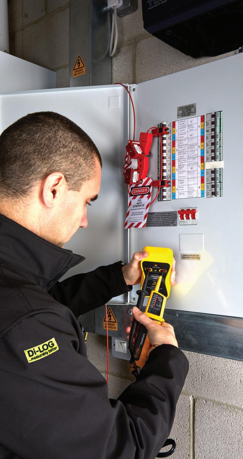
STEP 1: Check with the user that the supply is safe to isolate
STEP 2: Prove that your voltage indicator operates correctly with an approved proving unit
STEP 3: Test the circuit that you are isolating is powered off by performing the following combination of checks: Line-Neutral, Line-Earth and Earth-Neutral
STEP 4: Re-prove that your voltage indicator operates correctly with your proving unit
STEP 5: Refit the cover on the distribution board, Lockout and Tagout
STEP 6: Re-test again on the circuit that you are working on to confirm it is safely isolated
Covid-19, however, this does translate that you have roughly a 1 in 22 chance of being fatally injured if you are involved in an electrical incident in the UK To put this into a little more perspective, this is a dramatic difference compared to the 1 in 500 from other causes.
As well as electric shock, other electrically related injuries arise from burns, arcing and fires Many of the injuries can take a long while to heal and often result in life-changing conditions
With the 18th Edition AM2 now in full effect, safe isolation is continuing to be enforced across the industry, especially by bodies such as the NICEIC and NAPIT Although nothing has changed in the way of the testing requirement on installation test equipment, safe isolation is critical for the safety of yourself and the others around you
The preferred method is to isolate equipment or circuits using the main switch or distribution board switch disconnector The method of isolation should be locked off using a unique key, retained by the person carrying out the work, and a caution notice posted at the point of isolation
Where more than one operative is working on a circuit, a multi-lock hasp can be used to prevent the operation of the main isolator until such time as all persons working on the installation have completed their work and removed their padlocks from the hasp
”The practice of placing insulating tape over a circuit breaker is not an adequate or acceptable means of securing the device in the OFF position ”
Following the isolation of equipment or circuits and before starting work, it should be proved that the area you are about to work on is in fact dead The recommended method for doing this is by use of a test lamp or a two-pole tester (as recommended in HSE Guidance Note 38)
The test lamp or voltage detector should be proven to be working on a known live source or a proprietary
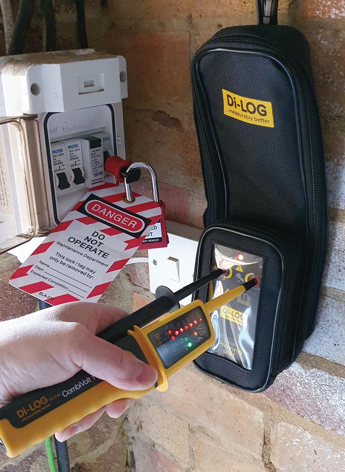
The Di-LOG range of ‘Lockout Kits’ are designed with safety, versatility and affordability in mind With the entry-level DLLOC1 – Personal Lockout Kit, you get a 38mm steel padlock, a universal MCB lock, a standard ‘pins-out’ MCB lock and a warning tag
The higher the level of the kit the more features are included By adding items such as multiple isolation lockout hasps the kits enable multiple persons to work on the same circuit, with the ability to hold up to six lockout padlocks
The DLLOC3 – Professional and DLLOC4 – Expert kits provide more scope to safely isolate a broader range of MCBs and main switches Items such as the larger universal MCB lockout device, large main switch lockout device, a fully insulated padlock and hasp, ensure all commercial and industrial applications are covered
proving unit All line, neutral, and protective conductors should be tested to prove they are dead
Electricians who regularly work on installations that have been energised should be equipped with devices for proving that conductors are dead Di-LOG’s latest range of safety equipment for working on LV Electrical Equipment includes an array of Lockout Kits, ranging from a simple single MCB ‘Personal Lockout Kit’ for isolation of individual circuits to the industrial ‘Expert Lockout Kit’ with mostly fully insulated lockout devices for virtually all individual and main sources of energisation.
GET MORE DETAILS ABOUT DI-LOG’S RANGE OF LOCKOUT KITS AT: WWW.RDR.LINK/EAN021
SECTION 1 ENDS!
SCAN THE QR CODE TO CLAIM YOUR CPD CREDIT FOR THIS SECTION OR VISIT

WWW.RDR.LINK/EAN041


BS 7671 Chapter 41 deals with protection against electric shock, and this is where the requirements for automatic disconnection in case of a fault can be found

The disconnection times stated in Table 41 1 are influenced by the type of earthing system and the voltage range used. Also, RCDs are included within the design for fault protection for certain installations, meaning there are many different parameters to be met
In general, there are two aspects involved with this protective measure:
● Basic protection is used to prevent contact with live parts, and
● Fault protection is provided by the protective earthing system and automatic disconnection in case of a fault
Fig 1 relates to TN systems and shows the
path of the Earth fault current in the event of line to Earth fault in one of the circuits. For clarity, only one circuit is shown, and it supplies a load with a metal casing that is connected to the Earth via the circuit protective conductor (CPC) The example shown is for a TN-S earthing system
The direction of the Earth fault current path is indicated by the arrows in Fig 1 It will be observed that the fault current flows in a loop It returns back to the supply transformer via the protective conductors, then goes through the winding of the transformer and returns to the fault within the installation via the line conductor
For TT systems, refer to Fig 2, where the mass of Earth between the installation and the origin forms part of the Earth fault current path
The resistance met by the fault current is known as impedance due to the presence of the transformer winding in the path, and the symbol for impedance is Z This fault path is called the Earth fault loop impedance and is abbreviated to Zs
The unit of impedance is the same as the unit of resistance, which is an ohm. The intention is that the fault current will be high enough to disconnect the overcurrent protective device within the required time, known as the disconnection time
The value of the Earth fault current is directly related to the value of operating voltage and Earth fault loop impedance, known simply as Ohm’s Law
Therefore, the lower the value of Zs, the higher the value of the Earth fault current and the quicker it will operate the protective device in order to disconnect the faulty circuit.
As the severity of an electric shock depends not only on the value of the current flowing but also upon the time that the current flows, BS 7671 quotes the maximum disconnection times for each type and rating of overcurrent protective device This means that the protective device of the circuit must operate to disconnect the electricity supply within these times in the event of a fault to Earth
Regulation 411 3 2 2 states that disconnection times in Table 41.1, found in
The experts at NAPIT take a closer look at the requirements for automatic disconnection in case of a fault.
BS 7671, shall be applied to final circuits with a rated current not exceeding:
● 63 A with one or more socket-outlets, and
● 32 A supplying only fixed connected current-using equipment.
The disconnection times for 230 V AC final circuits, found in Table 41 1, are:
● 0 4 s for TN systems
● 0.2 s for TT systems.
You should be aware that when disconnection is achieved in a TT system by an overcurrent protective device and protective equipotential bonding of all extraneous-conductive-parts has been carried out, in accordance with Regulation 411 3 1 2, the maximum disconnection times for TN systems may be used
In distribution circuits, i e , sub-mains, and for final circuits not covered by Regulation 411 3 2 2, Table 41 1 does not apply In TN systems, the disconnection time must not exceed 5 s; in TT systems, the disconnection time must not exceed 1 s (see Regulations 411 3 2 3 and 411 3 2 4)
When the Earth fault loop impedance, Zs, is measured using an Earth fault loop impedance tester, the reading obtained must be less than the relevant maximum value of Zs in the appropriate table.
Maximum Zs values are given in BS 7671
Tables 41 2, 41 3 and 41 4 The headings of these tables must be carefully noted to understand how each table is to be used
It should be noted that BS 7671 Tables 41 2, 41 3 and 41 4 all have a similar note at the end of the table.
This note states that the maximum impedance given in the table should not be exceeded if the impedance is measured when the circuit conductors are at their maximum operating temperature (i e , 70°C) Usually, the circuit conductors will be at much less than this when testing is carried out They may be assumed to be 20°C
Values taken at 20°C can be corrected to 70°C for 70°C cables by multiplying the maximum value of Zs by 0 8, as stated in Appendix 3 of BS 7671
Maximum Zs figures for commonly used devices, corrected for temperature, are produced in Table 1
RCDs used for fault protection
For TT Earthing systems, RCDs are often used to provide fault protection This is mainly due to the fact that Earth electrode
resistance is too excessive to meet the maximum Earth fault loop impedance requirements for the circuit’s protective device It is important that the electrode resistance remains stable and therefore should be as low as practicable (under 200 Ω is deemed satisfactory) Table 41 5 of BS 7671 lists the maximum Earth fault loop impedance values to ensure effective RCD operation, as summarised in Table 2.
Conclusion
We commonly see multiple protective devices used throughout installations, with ratings for different applications It is vital inspectors are careful to note the exact characteristics of the device to ensure the correct look-up table is used to confirm ADS can be achieved
When I first came across the above quote, I thought it would be from one of the great business minds or geniuses It was, in fact, said by Dwayne Johnson, otherwise known as wrestling superstar, The Rock
The Bright ‘Operations sector’ is about consistency of the ‘work’ of your business, the products and services it delivers The Operations sector is one of the ‘legs’ of our Bright 7 sector


model When you strengthen it to carry the weight of your business, you can grow bigger, go further and achieve things faster
To carry out installations consistently and to a high standard we use the following W O R K S process:

For this, we’ll utilise another acronym –F L E X – to ensure your systems are flexible, yet can still work under pressure
F
Map out your customer journey from start to finish A good idea is to create a flowchart with post-it notes or use a whiteboard This will help you to identify where things are working (or not) and can assist with identifying bottle necks or hot spots

L
Using the flowchart, we now need to ‘brain dump’ from all the team into a ‘how to’ manual List down (in step-by-step checklists) exactly how each area of the business works, much like a recipe book This does not have to be just text, it can be supported with photos, videos or screen captures
In order to engage the team with new or existing systems they need to be involved Training or brainstorming with them to get their ideas for improvements is crucial as they will know where problem areas are By showing that you’re willing to implement their ideas your team are much more likely to get behind them and will be more engaged in the business
The X-Factors are the ‘wow’ elements of your business – the things that will make your customers say: “wow that’s amazing” It’s those little touches that add to the experience and stay in your customers’ memory, meaning they’re more likely to tell others about you, helping you to win more referral work.
THE SECOND LETTER IN W.O.R.K.S IS ‘O’ WHICH STANDS FOR OPTIMISE. Once you've mapped out your flowchart, it’s time to look for ways to optimise it by improving existing systems or adding new technology to create better efficiencies
Could there be a better software system? Does your phone system need upgrading to incorporate things like VOIP, on-hold sales information or auto-attendant call routing? Does your website need an overhaul to include pop-ups, call backs or a live chat

option? Can you improve on training? There’s some excellent field service operations software systems available in the market, such as simPRO, which manages your operations from enquiry to invoicing Our clients love it, but we’ve found that you really need to have an office team member to use it well. For smaller 1-5 employee companies that may utilise their van as their office, the likes of Tradify, Servicem8 or Klipboard can be used
THE THIRD LETTER OF W.O.R.K.S IS ‘R’ WHICH STANDS FOR RESULTS. Ultimately, if you want to produce a great result for your clients you need to incorporate an element of project management to make sure they're getting what they want By managing the whole process and delivering the results along the way, you’ll start to realise that this is where the magic happens!
THE FOURTH LETTER OF W.O.R.K.S IS ‘K’ WHICH STANDS FOR KNOWLEDGE. This is about protecting the knowledge in your business Are you backing up your computers into the cloud? Have you got Disaster Recovery plans in place to keep the business running in the event of an emergency? How can you make sure that the information that might be in team members’ heads remains in your business?
THE LAST LETTER IN W.O.R.K.S IS ‘S’ WHICH STANDS FOR SPECIALIST. Finally, I would highly recommend that you have a ‘specialist’ in the business –someone who works specifically on operational organisation This could be an Operations Director/Manager and really needs to be someone who knows how to make sure that all the things you undertake as a business are done well, consistently and managed properly across the whole company

before we start, it should be noted that such types of storage media may be connected in various configurations to the host installation and/or any embedded generation. Manufacturer’s instructions should always be consulted
Any EESS consists of a number of component parts, including:
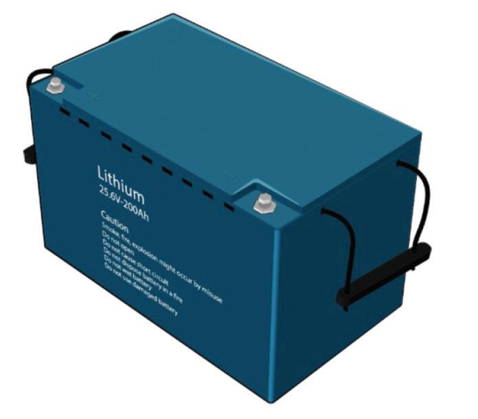
● Batteries
● Inverters
● Charge/discharge control equipment
● DC/DC conversion equipment
● Thermal management equipment
● EESS control equipment
● Independent earthing arrangement (where required)
● Monitoring and metering equipment (not discussed here)
All of these components may be arranged in a series of modules comprising several of the individual functions Their functionality is summarised in this article.
Within the scope of BS 7671, that is operating at a voltage not exceeding low voltage, an EESS may be categorised as a:
● residential EESS, or
● commercial and industrial EESS

An EESS may be designed and built for a particular application or it may be assembled from a range of component parts to provide the desired functionality. A self-contained EESS system is one in

which the components have been matched and assembled at the factory and is ready to be installed on delivery to site
Although exact terminology used in the various standards and guidance documents varies, an EESS may be constructed from a number of subsystems, including:
● the control subsystem containing the communication, management and protection functions and the user interface, and
● the primary subsystem containing the energy storage and power conversion functions and the point(s) of connection to the electrical power system
The two most commonly employed battery types in an EESS are deep-cycle lead-acid and lithium-ion
The following characteristics and factors will have an influence on choice of battery type employed:
● Operational lifespan.
This can be affected by a number of factors including:
■ The frequency of discharge, and
■ The depth of discharge (DOD) (greater DOD generally equates to shorter battery life)
■ Characteristic calendar life (projected life irrespective of usage)
■ Overcharge tolerance (lithium-ion batteries are more prone to damage than lead-acid)
● Required effective/usable energy storage capacity
● Charge/discharge efficiency. This can be affected by factors such as:
■ Battery type
■ Ambient temperature
■ Battery operational temperature
■ Battery age
■ Frequency of maintenance
● Required recovery time.
This is the time needed by an EESS, for the specific operating mode and operating conditions, to recover from a duty cycle so that it can be sufficiently recharged to serve the following duty cycle
Generally, lead-acid batteries perform less well across most of the above categories. However, they may still offer
the most cost-effective option in some cases based on the nature of the system and operational expectations
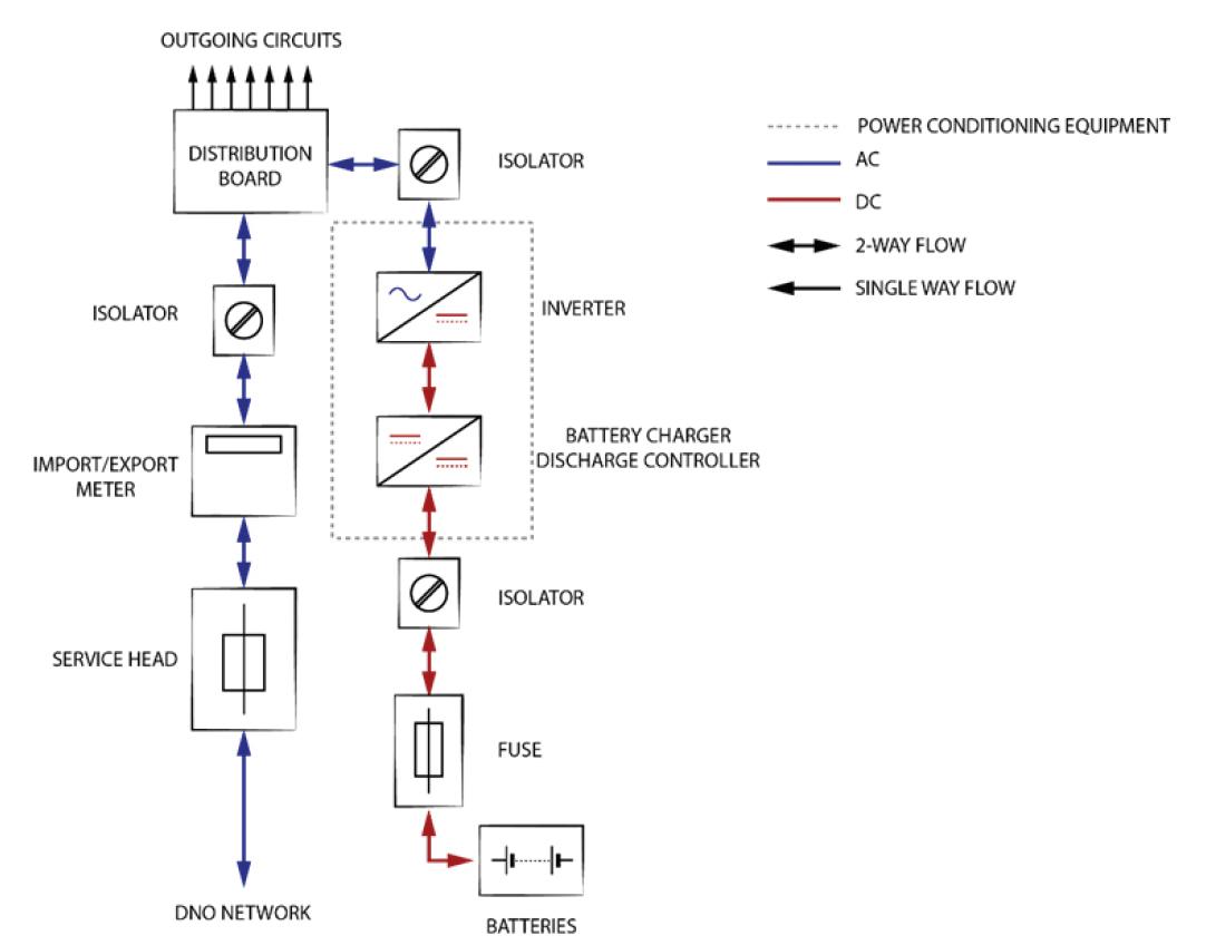
The arrangement of individual batteries or cells to create batteries/battery banks in order to achieve the desired terminal voltage and output current can vary. A system containing battery storage but no local generation is defined as a battery energy storage system (BESS) (see Fig 4)
Inverters: types & characteristics
An inverter is a static semi-conductor device (power converter) which converts DC to AC. Inverters often include additional functionalities, discussed later in this article
A number of types of inverter may be employed within an EESS to permit:
● Grid connection
● Standalone operation (without grid connection)
● Combination grid/standalone operation
● Bi-directional operation, which can allow output to the grid and/or the installation and also act as a charger for the storage batteries. Both grid connection and standalone bi-directional inverters are available
It should be noted that where an EESS is installed at a premises with an existing PV system designed to operate in parallel with the DNO supply only, and is not forming part of a prosumers low-voltage installation (PEI), the associated inverter will shut down when loss of mains or fluctuation in the supply characteristics outside of nominal parameters is detected
If any form of continued battery charging and/or operation of loads within the premises is required a second inverter or other power conversion equipment (charger/charge controller) will need to be
installed or the existing inverter could be replaced
This may be seen as the favourable option where the inverter has been operating for some time, as inverters are often the first component to fail and may be near end of life
In an EESS, an inverter/battery charger is a two-way device which converts:
● DC power from the batteries into AC to supply loads within an installation, and
● AC energy into DC energy to charge batteries
A charge controller sends power in one direction only to charge the batteries whilst also preventing current from draining back into the source of supply.
Inverter/chargers are not designed to charge batteries directly from the DC current provided by an unstable source such as, for example, a PV system A charge controller is needed to match the PV output voltage to the battery and to regulate charging.
In general, an EESS will contain both an inverter/battery charger and a charge controller to ensure optimum functionality and efficiency
In the case of an EESS utilising a PV generator, there may be insufficient capacity to charge the storage batteries effectively using a charge controller alone in the winter or during extended periods of cloudy weather This can affect energy availability and so an inverter/charger will be required to keep batteries adequately charged from the grid supply.
A DC/DC converter makes it possible to:
● Raise/step-up battery output voltage
● Provide a constant DC output voltage regardless of fluctuations in battery output voltage
● Provide galvanic isolation of the battery from the rest of the EESS to provide, for example, corrosion mitigation
It can also simplify the matching of multiple battery sets to the EESS.
Battery discharge controller

A discharge controller can provide the following:
● Control of the rate of discharge
● Prevention of further discharge of batteries when their depth of discharge (DOD) limit is reached (that is, the percentage of total capacity that can be utilised)
● Feedback on battery temperature to optimise efficiency and/or minimise damage
● Control of the times at which batteries can discharge to loads
● Prevent discharge until battery charge thresholds have been reached
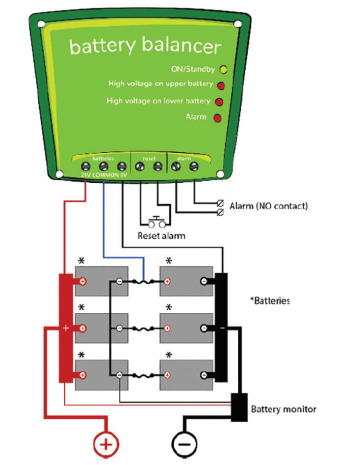
Battery balancer
The service life of batteries forming part of a bank can be shortened considerably by a charge imbalance
A cell or battery having even slightly higher internal leakage current in a bank of several series connected cells or batteries will cause undercharge of the whole battery in relation to the other cells or batteries to which it is connected in series, which may also be subjected to overcharging
Left untreated this can set up a cyclical passage of current between batteries or cells and a resultant temperature increase or thermal runaway. Overcharging can cause damage due to excessive gassing.
In the case of L-Ion batteries the aforementioned effects can result in an explosion and/or fire hazard For lead-acid batteries, undercharging can cause sulphation of the batteries/cells with the lower initial state of charge
Although varying in complexity, thermal management systems maintain the component parts of an EESS within their normal operational temperature limits to maintain functionality and efficiency and to prevent thermal damage At the most basic level, this could be a thermal cut-out In more complex systems, particularly where continuity of supply is essential, it might trigger cooling equipment to start and/or instigate some degree of non-essential load shedding
This term is often used where multiple components/functions such as inverters, battery chargers and controllers, DC/DC converters, battery discharge controllers and thermal management equipment are integrated into a single unit

This may monitor the availability and quality of the connected sources of supply, control charge and discharge operations and may also interface with external resources such as those of distributors and suppliers. It may also instigate other actions such as making/breaking the connection to a public distribution network, load shedding, information exchange and provision of information to building user/operator

An EESS operating in Island mode; that is, where supply to all or part of an installation is maintained from internal sources although the supply from the grid has been disconnected, cannot rely on the earthing arrangement provided by distributor when running independently of the DNO supply (551 4 3 2 1) as doing so could place persons working on the distribution system in danger
A typical EEES consists of a number of component parts designed to provide a system which is both economical and remains reliable for its predicted service life An EEES may be assembled from a number of components or sub-sets, or may be manufactured as a self-contained system
The column where you get to put your lighting questions to the head of the Ovia lighting business, Mike Collins, and his team of technical experts
BEEN ASKED TO QUOTE FOR LIGHTING
TO BE SUSPENDED OVER A NUMBER OF SNOOKER TABLES APPARENTLY, THERE IS A CIBSE AND SPORTS ENGLAND (LG4) REQUIREMENT THAT THE LIGHT VALUE SHOULD BE 500 LUX ON THE TABLE WITH A MAX OF 0 8 REDUCTION FACTOR THE CUSTOMER IS CONCERNED THE FULL LED MAY HAVE A HIGH GLARE FOR THE SNOOKER PLAYERS AND THAT PARTS OF THE EXTREMES (POCKETS) MAY BE IN SHADOW. CAN YOU SUGGEST CAT 2 OR DIFFUSED LIGHTING THAT CAN REDUCE GLARE? THE TABLES ARE FULL SIZE (12 FT X 6 FT), WITH A REFLECTIVE INDEX IN THE LOW 40S OR LATE 30S
The guidelines for snooker are split into three categories based on the level of competition that is being played
Assuming that this isn’t elite level snooker and is more toward recreational, for this application 500 lux is required on the table with a desired unifor mity of 0 8 This is quite a high level of unifor mity and should ensure vir tually no shadowing
Unifor mity is the ratio of the minimum lighting level to the average lighting level in a specific area, in this case a snooker table. The higher the level of unifor mity the less difference there is between the minimum and average level of illumination If the customer has concer ns regarding the glare, we’d steer more toward a UGR friendly luminaire UGR stands for unified glare rating and measures the amount of discomfor t causing glare UGR 19 is considered a good level of glare for wor king at a computer and is at the lower end of the glare rating. In summar y, we would aim to achieve 500 lux with a unifor mity of 0 8 using a UGR 19 luminaire The Ovia Inceptor Slate is a premium range of LED panel lights with a low UGR19 diffuser, making them ideal for this type of installation


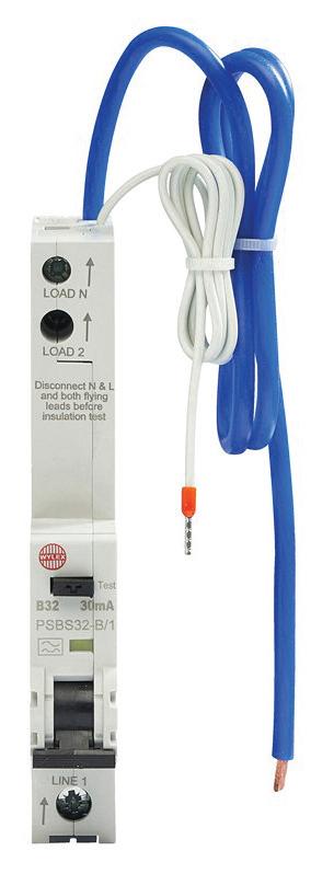
In the workplace power continuity is an important factor. Business services must not be interrupted by unwanted power outages That’s why RCBOs (Residual Current Breaker with Over-Current) should be used when there is also a requirement for 30mA protection for the users of the installation Additionally, personal safety is an equally important factor
Protecting users to Amendment 2
Regulation 411 3 3 of the Wiring Regulations was revised by Amendment 2 This regulation now requires additional protection by means of a 30mA device for users of socket outlets (not rated higher than 32A) in locations where they’re liable to be used by persons of capability BA1, BA2 or BA3
The terms BA1, BA2 or BA3 probably need some further explanation Appendix 5 includes a list of external influences, and under the sub-heading of ‘Utilization’ BA refers to the capability of persons BA1 is described as an ordinary person (a person
who is neither a skilled person nor an instructed person) BA2 as children, and BA3 as disabled
No exceptions permitted
So, in all locations where socket outlets (not rated higher than 32A) are liable to be used by ordinary persons, disabled persons, or children, additional protection by use of a 30mA device is mandatory No exceptions are permitted
Providing protection
Providing additional protection and maintaining power continuity is actually quite easy Each circuit should be protected by an individual Type A 30mA RCBO This will meet the requirements of Regulation 411 3 3 and the requirements of the business because it will eradicate unwanted tripping and guarantee that all healthy circuits remain in service.
Other considerations
In a modern workplace, school or
university environment, for example, the connected equipment, and portable devices will have a significant impact upon the design of the installation and will no doubt bring DC influences and PE currents into consideration for both the designer and installer
Regulation 531.3.2 requires protective conductor currents (standing earth leakage not due to a fault) to be limited to 9mA for a 30mA device in order to help to avoid unwanted tripping, but that can’t be achieved if several circuits are protected by one device
Designers will not only have to take account of PE currents when dividing the installation into the necessary number of circuits, there are also the requirements of Chapter 31 & Regulations 314 1 to consider Regulation 314 1 requires the installation to be divided into the necessary number of circuits to:
-
the possibility of unwanted tripping of RCDs, - facilitate safe inspection, testing and maintenance
Wherever additional protection by a 30mA device is required each circuit should be served by an individual Type A RCBO in order to meet the requirements of BS7671, including Amendment 2
Amendment
to the 18th Edition Wiring Regulations, the team at Electrium provide us with more detail as to the correct use of RCBOs in the workplace.
The experts at Vent-Axia provide advice on Part F of the Building Regulations for commercial and industrial buildings.
Part F of the Building Regulations came into effect from 15th June 2022, but how do they affect commercial and industrial clients?
With Part F (Means of Ventilation) focusing heavily on health and wellbeing, a key addition to the document is a new section on monitoring indoor air quality (IAQ) Other key points include designing ventilation systems to minimise external pollutants entering indoor spaces, and assessing ventilation requirements when installing energy efficiency measures to ensure good IAQ.
The scope of Part F of the Building Regulations covers both new build and refurbishment and now looks to both minimise the entry of external pollutants and ensure humidity and pollutants are extracted effectively and efficiently. The document also includes guidance on minimum levels of air quality, to ensure good occupant health, and considers ways to monitor IAQ as part of this Furthermore, the document looks at energy efficiency and ventilation requirements
While the Regulations cover both residential and commercial, a new change
for the Building Regulations is that flats with communal areas are now seen as commercial rather than residential buildings
With the pandemic highlighting the importance of good ventilation to mitigate virus transmission, Part F is also introducing improvements to ventilation in new non-residential properties to help prevent the spread of airborne viruses In fact, it states that in “locations where continuous talking or singing takes place, or there are high levels of physical activity (such as dancing, playing sport or exercising), providing ventilation sufficient to keep CO2 levels below 800ppm is recommended”.
There is also a sub-section entitled ‘Indoor Air Quality Monitoring’, which states that in new buildings in the occupiable rooms it refers that there “should have a means of monitoring the indoor air quality. This may be achieved using CO2 monitors or other means of measuring indoor air quality ” These actions will help ensure better indoor air quality in non-residential properties

Published on 15th December 2021, the Building Regulations are being hailed as a “vital step to improve indoor air quality”.
Vent-Axia is well prepared for the amendments to Part F for non-residential properties, with a wide range of sensors. These include sensors for CO2, which can be discreetly located on a wall and can intelligently boost ventilation based on the detected CO2 levels They can also provide a warning indication for occupants if CO2 levels rise above acceptable levels with a useful traffic light system on the front, so occupants can activate purge ventilation when required
These sensors are designed to work in conjunction with a wide range of ventilation solutions including the Sentinel range of demand controlled inline fans, suitable for either supply of fresh air or extracts of stale air. The inclusion of a CO2 sensor in the control provides optimal air quality control while minimising the actual running costs of the fan
For more simplistic ventilation solutions where ducting cannot be easily installed Vent-Axia’s Lo-Carbon T-Series fans can provide background or purge ventilation and are easily fitted to an existing window or through a wall

DANNYHARMSWORTH: WE CAME ACROSS THIS ON A RECENT JOB: A SOLAR INSTALLER TOOK THE POWER FOR THE SOLAR CONSUMER UNIT DISTRIBUTION BOARD STRAIGHT OFF THE
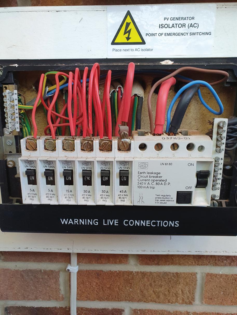
NO OVERCURRENT FUSING USING 2.5 MM PVC T WIN AND EARTH CABLE – VERY DANGEROUS, I THINK!
As m o re s o l a r P V i n s t a l l at i o n s a re re q u e s te d, t h e re i s a g o o d c h a n ce we w i l l s e e s o m e p o o r q u a l i t y i n s t a l l at i o n s a l o n g t h e way – i n s t a l l at i o n s w h i c h r i s k b e i n g p u t to g e t h e r w i t h l i t t l e o r n o b a s i c u n d e r s t a n d i n g o f s o l a r P V s ys te m s o r t h e i r i nte grat i o n w i t h a n e x i s t i n g i n s t a l l at i o n by d e s i gn e r s o r co nt ra c to r s
Th e i n s t a l l at i o n i n t h i s p h o to a l s o s h ows a l a c k o f b a s i c u n d e r s t a n d i n g o f i s o l at i o n , a s t h e P V co n s u m e r u n i t c a n’t b e i s o l ate d a s i t ’s fe d f ro m t h e i n co m i n g s i d e o f a n i s o l ato r, w h i c h a l s o m e a n s i t wa s p ro b a b l y e n e rgi s e d w h i l e l i ve !
A P V i nve r te r m ay b e s u p p l i e d by a s u b - b o a rd, a s t h e i n s p e c to r p o i nt s o u t , b u t t h e s u p p l y to i t , w h i c h i s e f fe c t i ve l y a s u b - m a i n , n e e d s to b e d e s i gn e d a n d co n f i g u re d co r re c t l y. Th e s t i c k e r s t at i n g ‘AC I s o l ato r ’ i s a l s o i n d i c at i n g t h at t h e m a i n C U i s p rov i d i n g i s o l at i o n Th i s i s n o t t h e c a s e, a n d e ve n i f t h e s u b - m a i n we re fe d f ro m a n M C B, t h i s s t i l l wo u l d n’t b e
t h e c a s e Th e i s o l at i o n n e e d s to b e v i a a s e p a rate d e v i ce, w h i c h m ay o r m ay n o t b e t h e s u b - b o a rd ’s m a i n i s o l at i n g s w i tc h Th e t y p e s o f d e v i ce s u s e d m u s t a l s o b e c a p a b l e o f o p e rat i n g u n d e r o p e rat i n g co n d i t i o n s t h at w i l l a l l ow c u r re nt f l ow
b i - d i re c t i o n a l l y, a s t h i s i s a re q u i re m e nt fo r a l l ow i n g t h e g e n e rate d e n e rg y to f l ow i nto t h e u s e r ’s
n e t wo r k
S o l a r P V i n s t a l l at i o n s
c a n b e co m p l e x a n d m u s t
b e d e s i gn e d a n d i n s t a l l e d
by a p p ro p r i ate l y s k i l l e d
a n d co m p e te nt p e o p l e.
Wh i c h e ve r way we l o o k at
t h i s, a l a r m b e l l s w i l l b e
r i n gi n g d u e to t h e p o o r d e s i gn c h a ra c te r i s t i c s b e i n g d i s p l aye d. The Observations, Regulation infringements and Codes applicable to this observation would be:
Need help with cracking those all-impor tant EICR codes? Ever y month the technical team at NAPIT will be studying your latest ‘Caught on Camera’ photos and offering advice on the next steps, should you find a similar installation. If you want the team at NAPIT to help crack your codes then send your pic tures through to us at: pe@hamer ville.co.uk
Whether its fault finding or an EICR, an inspector needs to understand or have a good work ing k nowledge of previous installation techniques and legac y equipment available to an installer at that given time. Equipment and advanced termination devices that we use today simply weren’t around or commonplace 15+ years ago
H istorically, termination blocks and adaptable boxes (metal or plastic) were the ‘go -to’ wiring centres for many applications This t ype of arrangement was commonplace (as shown here in the photo) and I’d imagine there are thousands more still out there I f they ’re put together correc tly, they ’ll continue to give good ser vice with no requirement or need to upgrade them. Unfor tunately, they can wear with age, deteriorate and need replacement, as with any installation
I should also point out that I see numerous modern termination devices that are damaged by heat, incorrectly sized
or not fitted in accordance with their manufacturer ’s requirements, that have failed or caused more sinister damage

In general, the photo shows a site -built wiring centre that looks to have been put together as well as a site -built centre could be I t ’s not that visually stunning, admittedly, and could have been tidier, and some identification wouldn’t go amiss, but other than the thermal damage, is it a real issue?
The thermal damage to the terminal block could be heat build-up over many years, or it could be that the circuit has been modified past its original design parameters Larger capacity accessories may have been installed, which may have caused the thermal damage
Simply upgrading the damaged terminal block with a similar accessor y or a newer variant may not solve the problem I feel the whole circuit should be investigated to ensure that the existing accessories and replacements are adequately rated and consider any
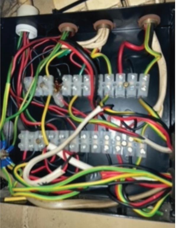
Although the original design may not be available, the equipment there now is available for inspection, and any design deficiencies can be understood via a retrospective circuit design process
The Observations, Regulation infringements and Codes applicable to this observation would be:

Thermal damage to terminal block
Possible circuit overloading and design issues
Possible multiple circuits may require identi cation

133.2.2, 133.2.4, 651.2 (ii)
133.2.2, 133.2.4, 512.1.2
134.1.3, 514.1.2, 514.1.3
 GERRY ARNOLD: WE DISCOVERED THIS LIT TLE FIND IN AN ADAPTABLE BOX AT A WORKING MEN’S CLUB WHERE THE W.C LIGHTS HAD STOPPED WORKING!
The experts at ECA explain more about the different types of control cables and why a new certification scheme should help to improve the quality of cables being sourced and used.

Control cables are found in a vast array of industrial and everyday applications These products are flexible, interconnecting and used to measure, control or regulate equipment like assembly or production lines, and to provide support for their associated computer units and work processes
Control cables are used when a direct connection to the controlled object is impossible As such, control cables can occupy an intermediate position between communication cables and power cables
A new BASEC certification scheme
Currently, these control cables are not governed by any specific standards, which can often confuse manufacturers, installers and users In response to demands from the marketplace to help address this problem, BASEC has launched a certification scheme to encourage standardised and consistent levels of quality for control cable product ranges Reflecting industry requirements, the new scheme refers to YY, SY and CY control cables.
What do YY, SY, and CY mean?
YY, SY and CY control cables are some of the most commonly used cables for applications such as industrial automation, railways infrastructure and more The cables transmit information about the location, status and operating condition of an industrial component being controlled YY, SY and CY originate from the European Committee for Electrotechnical Standardisation (CENELEC) naming conventions, where the first characters refer to the following:
● ‘Y' = unscreened
● 'S' = steel wire braid
● 'C' = copper braid
The second character, ‘Y', in each group refers to the material types – usually PVC – but the cable sheathing may also be a low smoke type SY control cable may also be referred to as flexible, braided, flex or instrumentation control cable.
YY cables are unscreened, flexible control cables available in various cores and conductor sizes
suited to environments with light mechanical stress.
SY cables have a braid of galvanised steel wire (GSWB); these cables are suited to installations with medium to high mechanical stress
CY cables are screened, flexible control cables with construction options similar to YY types but they include a tinned copper braid over the bedded, laid up cores – this extra braid adds protection against external electromagnetic influence
All control cables are available as PVC or low smoke emission versions (LSHF), depending on their application. Low smoke cable variations should be installed for environments where safety is critical, to limit the danger to life or equipment
Under the IET Wiring Regulations (BS 7671), YY, SY and CY control cables are not recommended for use as part of a fixed installation The IET’s supporting guidance states: "For the purposes of ensuring compliance with BS 7671, the installation and use of non-standard cables, such as SY, CY and YY cables is discouraged.”
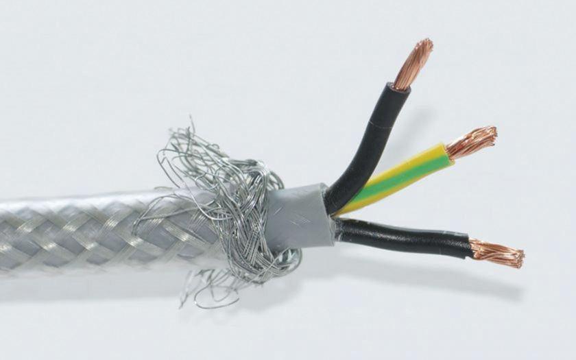
This means that a deliberate decision not to fully comply with the Wiring Regulations by using control cables in a fixed installation, must be noted as a departure Any use of a custom, non-standard, or partially compliant cable must be declared and assessed, and it
must be ensured that the degree of safety isn’t compromised
Some manufacturers claim that YY, SY and CY cables comply with the general requirements of the BS EN 50525 series (flexible cables) but these designs differ from the requirements of the mentioned standards For example:
The BS EN 50525 series BS EN 50525-2-11 is the British Standard for PVC flexible cables, but it has no provision for any braid Therefore, braided cable, such as SY cable, can’t conform to this standard
In 2017, it was reported that the insulation and sheath thicknesses of cables designated YY, SY and CY often have lower insulation and sheath thicknesses in comparison with the BS EN flexible cables Therefore BS EN 50525-2-11 is not an appropriate standard for YY, SY and CY cables
Some YY, SY, CY cables claim to be made to continental standards, though it is not clear what these standards are.
As an authority and preferred testing and certification partner to the worldwide cable industry, BASEC is regularly contacted to support and advise on control cable products' comparability and application
The BASEC scheme offers the cable industry and its users a way to improve and evidence the levels of quality and safety that the products manufactured, specified or sourced hold. There is
presently no referenceable standard for this, hence the reason these cable products are often a debated hot topic
The scheme comprises six BASEC specifications: BA 1411, BA 1413, BA 1415 for PVC design and BA 1412, BA 1414, BA 1416 for LSHF design
The new certification scheme is relevant to cable products up to and including 300/500 V, with a maximum conductor operating temperature of 70°C Where applicable, standards EN 50525-1 and EN 50565-2 will be referenced in conjunction with the control cable scheme document
BASEC is known within the industry for rigorous certification, factory auditing and testing schemes, which work continuously to improve the quality and safety of cable products at manufacturing sources With this in mind the new scheme has been developed, offering an all-inclusive testing programme for this widely used and barely regulated range of cable products


This article considers the function(s) of a communication Bus system, such as KNX, and its ability to permit interconnected control of devices using twisted multi-pair cable (KNX TP)
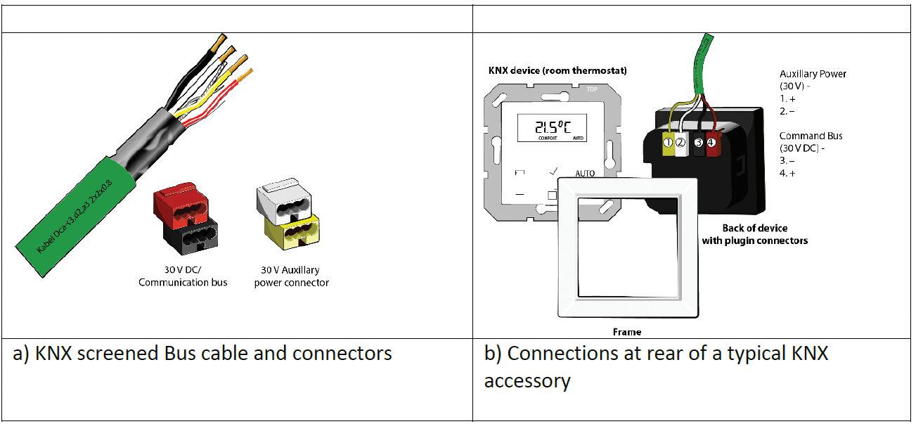
KNX is a control system based on a common standard for commercial and domestic building services automation that allows products from various manufacturers to work seamlessly together. Communication between devices is achieved using the dedicated KNX protocol, guaranteeing interoperability between the many manufacturers signed up with the KNX Association
The KNX standard allows communication through other types of media, offering a higher degree of flexibility in system design, however, only KNX TP will be considered in this article
Cables used with KNX systems are similar in construction to that of Ethernet cables, typically incorporating a foil screen protecting the twisted pairs1 from interference.
The conductors are terminated into dedicated connectors allowing for termination into any KNX device, as shown in Fig 1
The use of cable Bus systems is more often associated with larger installations such as commercial and industrial type premises However, such use is becoming increasingly popular when designing new installations for larger domestic premises
As shown in Fig 2, local lighting and shutter radial circuits can be connected directly into their output channels of the associated actuators which incorporate switching and dimming functionality, therefore negating the need for a conventional type localised wall switch2
Although actuators often have many channel outputs facilitating control of multiple circuits, consideration should be given for the provision of separate lighting circuits within larger installations over multiple actuators
Some devices offer means to measure current, switching cycles and power consumption within a circuit. Additionally,
a back-up function is often provided with manual on/off switching in case of communication failure on the Bus
Generally, some form of training in the installation and application of the chosen equipment will be necessary

The wired KNX system operates on a series of British Standards, BS EN 50090 and International Standards, BS ISO/IEC 14543-3. Each KNX device has the ability to function independently, thereby removing the need for a centralised control system Because KNX is an open protocol3 , communication between devices on the cable Bus is possible using around 6,500 products from 400 assigned manufacturers on any particular system
Many of the devices are typically DIN rail mounted in an enclosure often located adjacent to the consumer unit Although, flush type devices are also available, and commonly used in metal back boxes and ceiling voids within existing installations.
All input/output devices, including wall switches, sensors and actuators are interlinked to the KNX network Bus via a dedicated cable
Regulation 557.6.2 of BS 7671 recognises the need to take into consideration the characteristics of a cable when used in auxiliary circuits for the control of relays (actuators) The rated voltage of an auxiliary circuit, and the components used, shall be compatible with the supply to that circuit. Excessive voltage drop in
This article from the experts at NICEIC discusses intelligent cable Bus technology, such as the KNX system, for the connection and control of smart devices within a building, and as an alternative to using wireless devices.Fig 1 Typical KNX cable and device connections
an auxiliary circuit may reduce the reliability of operation of the actuators and other components within the system (Regulation 557 3 5 1)
In-line with the KNX standard, manufacturers of such control systems often specify a dedicated type of cable and a maximum length, to ensure signal quality and system reliability against issues such as voltage drop and, consequently, non-functioning devices
Although most commonly used cables incorporate two twisted pairs, the distribution of power and data signals (telegrams) within a KNX system typically share the same two-conductors, red (+) and black (-) A secondary pair, yellow (+) and white (-), is often included for the distribution of auxiliary power.
The cable’s inner foil screen protects the conductors from external interference, and is not to be considered as an exposed-conductive-part It is therefore, not necessary to connect the protective screen to the installation’s Main Earthing Terminal for reasons of safety.
Furthermore, as the system operation is not reliant upon a 0 V reference point, no such connection is necessary for functional purposes
Devices connected on the cable Bus typically receive a 21 V – 30 V DC supply from a DIN rail mounted SELV power supply Unit (PSU) A commonly used 640 mA PSU is normally capable of supplying up to 64 devices, although an increase in connected devices across separate Bus lines and line couplers in a system will
typically require separate PSUs
Typical devices connected to the KNX Bus line include:
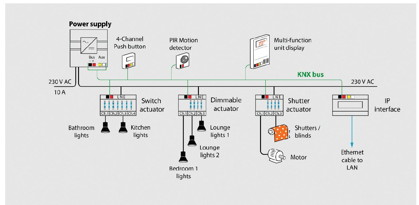
● IP interface module, a DIN rail mounted router allowing communication with the KNX Bus, required for all systems and used for programming and system configuration
● Single or multi-gang retractable wall switch, click for (off/on) or hold for dimming. Touch screen wall controllers are also available
● Actuators, remote contactors rated at 10 A – 20 A, consisting of 2 – 15 individual channels capable of switching and dimming including those used for RGB(WW)(CW)4 LED lighting
● Individual lighting sensors/heating thermostats
● Dedicated controllers and binary actuators allowing interlinking between third party non KNX devices
KNX cable Topology
Cables are generally arranged in radial circuits or Bus lines interconnecting devices throughout the installation (see Fig 2) Ring circuit arrangements are not supported
The wired network can be formed with line, tree and star topologies and can be mixed throughout an installation. Branches can be added to any point within the line, for example, during the extension to a building Additionally, devices can be connected and arranged in any order on the cable Bus with the final configuration of each KNX device carried out via application software.
Each Bus line is capable of hosting a maximum of 64 devices Although a line can be extended using ‘line repeaters’ to accommodate a further 191 devices However, such a configuration may reduce the system response time due to the increase in data traffic. For this reason, using separate ‘line coupler modules’ as an alternative for additional Bus lines takes advantage of the in-built filter function, for prioritising and organising data traffic (telegrams) for improved response time.
Summary
The benefit of the KNX system is its ability to operate on the basis of a decentralised structure Each intelligent device is processor controlled and can operate and monitor a circuit independently, removing the need for a centralised control, although this can be included if necessary
Using the KNX control system within an installation allows for the interlinking of a variety of different products from many manufacturers
The ease with which new devices can be added and integrated into the system make it a popular choice for new installations, irrespective of size and complexity
Key references:
1 Cables are available in single-pair or two-pair with a screen or un-screened
2 Flush mounted modules, wired or Rf, are available as an alternative to using DIN rail mounted actuators
3 An open protocol permits different manufacturers’ devices to interoperate without the need for a proprietary interface or gateway In short they talk the same language
4 LED lighting comprising either a combined red/green/blue/warm-white/cool-white chip or a red/green/blue chip and a separate warm-white/cool-white chip These combinations provide the richest colour mix when compared to other LED chip arrangements RGB(WW)(CW) requires five mixing channels and is often referred to RGB+CCT (Correlated Colour Temperature)
In any electrical installation, it is necessary to give adequate support to cables The reasons for this are twofold: a) maintenance of the signal pathway, and b) reduce the risk of premature collapse to protect firefighters accessing a premises during fire
Three specific life safety standards to be considered are:
● BS 5266-1: 2016 Emergency lighting –Part 1: Code of practice for the emergency lighting of premises;

● BS 5839-1: 2017 Fire detection and fire alarm systems for buildings Part 1: Code of practice for design, installation, commissioning and maintenance of systems in non-domestic premises;

● BS 8519: 2020 Selection and installation of fire-resistant power and control cable systems for life safety, fire-fighting and other critical applications – Code of practice
Other relevant references will be made to the requirements of BS 7671: 2018 Amd 2: Requirements for Electrical Installations
Emergency lighting
Emergency lighting systems require installed cables to be able to withstand the effects of fire as well as remain in-situ for a period necessary to ensure safe egress of persons To address these issues, Clause 8 of BS 5266-1 covers wiring systems and circuits in general For self-contained emergency luminaires, there is no recommendation for
fire-protected cables (clause 8 1), and the general requirements of BS 7671 will apply These include the need to support the wiring system in such a way that it is not liable to premature collapse (521.10.202).
However, where the emergency lighting system consists of a central battery, it is of critical importance that the quality of the installation, the fire-integrity of the cables and their supports is maintained. The risk of a loss of signal, and hence illuminance, is increased where poor installation practices are carried out (Note 1 Clause 8 2 1)
Clause 8 22 of BS 5266-1 details the nature of cable types recognised as being acceptable This clause details minimum cable survival times, ranging from 60 minutes to 120 minutes.
Without suitable survival times for the support of such cables, it will be impossible to ensure circuit integrity The methods of cable support and fixings should be non-combustible and such that circuit integrity will not be reduced below that afforded by the cable used (Clause 8.2.3). This means, for example, that where a cable is rated as ‘enhanced emergency lighting cables with inherently high resistance to attach by fire’, the support means should also be capable of performing its function for 120 minutes
Furthermore, where cable management system support is provided by drop rods, the drop rod size should be calculated in accordance with the recommendations of BS 8519
The commentary to clause 26 of BS 5839-1 recognises that all interconnections must operate correctly at the time of a fire Clause 26 2 recommends that cables forming part of the critical path conform to certain
standards. These include mineral insulated copper sheathed cables, cables conforming to BS 7629-1, and the like
Like the recommendations of BS 5266-1, clause 26 2f ) of BS 5839-1 recommends that methods of cable support should be non-combustible and such that circuit integrity is not reduced below that afforded by the cable used, and that they should be able to withstand a similar temperature to that of the cable being supported This recommendation, in effect, precludes the use of plastic cable clips, ties and trunking as means of cable support.
Installation of fire-resistant power and control cable systems for life safety systems

As with both emergency lighting systems and fire detection and fire alarm systems, BS 8519: 2020 addresses the need to ensure cable support systems are adequate to meet the fire survival times of the cables they support
The recommendations found in BS
8519 are like those detailed in both BS 5266-1 and BS 5839-1. However, additional guidance is provided where a bracket and rod system is used to support safety critical cable systems Clause 16 of BS 8519 recognises that the strength of steel is adversely affected by fire such that great care should be taken in determining the cross-sectional area of the steel rod drops
Conclusion
It is essential that great care is taken when installing cables supplying life safety systems, such as fire detection and fire alarm systems, emergency lighting systems and fire-fighting lifts The installer must use appropriate cables and support systems to ensure that critical systems continue to function during fire
GET MORE DETAILS ABOUT THE UNICRIMP RANGE OF FIRE SAFETY PRODUCTS AT: WWW.RDR.LINK/EAP017
In terms of explosive risk, a hazardous area is an environment in which an explosive atmosphere is present (or may be expected to be present) in quantities that require special precautions for the construction, installation and use of equipment In this article we explore the challenges faced in the workplace, the risk control measures, and the required competencies to work safely
Fire and explosion are, without doubt, a major hazard and one that electrical contractors may face in a range of projects and working environments
It is a consequence of modern life that we manufacture, store or handle a range of gases or liquids that are deemed flammable, and a range of dusts that are
deemed combustible These substances can, in certain conditions, form explosive atmospheres and these can have major and tragic consequences
Most of us are familiar with the fire triangle – remove any one of the three elements and the fire cannot occur, but what does this mean in the context of hazardous areas? When breaking this down into its simplest terms it is essentially:
● a combination of a certain amount of release or leak of a particular substance or material,
● mixing with ambient oxygen, and
● the presence of a source of ignition
While we can introduce various measures to prevent an unintended release of a flammable or combustible material, we cannot completely rule this out. In most
instances, we can do little about the levels of oxygen in the air, but we can have significant influence on sources of ignition, for example electrical equipment
Hazardous areas are documented on the hazardous area classification drawing and are identified on-site by the triangular “EX” sign Here, amongst other key information, zones are split into three types depending on the hazard, the likelihood and duration that an explosive atmosphere will exist; Zone 0 or 20 is deemed the most hazardous and Zone 2 or 22 is deemed the least.
It is in these areas that we find specific requirements for the types of electrical equipment and installations that are designed not to present a source of ignition The methods by which this is achieved can vary so it is critical that the special features of this electrical equipment
and installation is not compromised
Have you heard of terms such as “flameproof ” , “increased safety” or “intrinsic safety”? Identified by special markings, these are just a few examples of the types of protection (or protection concept) employed by the electrical equipment and installation
To preserve these special features requires a combination of the correct design, equipment selection and installation techniques This is then verified through inspection and testing and is preserved throughout the life of the installation by employing the correct maintenance techniques, supplemented by periodic inspection
When all these measures are taken, they should also be documented The verification dossier includes information such as the hazardous area classification drawing, manufacturers’ documentation, equipment certification, design drawings
and calculations, inspection records, and records of a person’s competency and continuing professional development (CPD), such as via ECA’s eCOMS software
Given the potential consequences of an explosion and the specialist nature of these activities, it is vital that those undertaking this work are competent to do so CompEx is the international scheme for competency validation and certification of those who work in explosive atmospheres, offering a range of qualifications to develop and verify a person’s knowledge and skills through a combination of training and assessment
The scheme has qualifications for a variety of employees working in all industries at varying levels Non-technical staff may attend a Foundation Course (ExF) to gain an overall appreciation of the
hazards and control measures, whilst technicians may undertake a more specialised qualification This addresses the requirements associated with equipment selection, installation, maintenance and inspection.

CompEx also offers qualifications aimed at those who are responsible for the design and management of installations and the persons employed at hazardous installations
The subject of hazardous areas is a very serious one, with some unique challenges. CompEx, therefore, provides a methodology that can offer verifiable core competency validation against a range of activities and hazardous areas
GET MORE DETAILS ABOUT COMPEX TRAINING COURSES AND DATES BY VISITING: WWW.RDR.LINK/EAP018

Leaving the lack of competence shown by the initial installer of these floodlights aside, more so than ever, we can see why regular periodic inspec tion of elec trical installations is necessar y
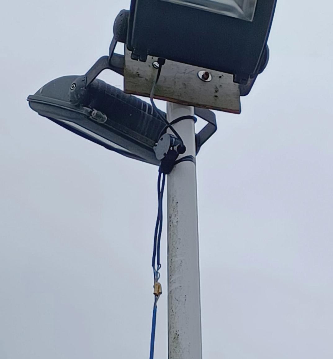
There are numerous infringements of BS 7671 here, so I’ll tr y and deal with them on a sequential basis.
Firstly and most serious is the access to live par ts from the termination blocks that are exposed I n ex treme cases of weather, these could easily contac t the post and cause a potential shock risk for anyone touching it As the terminal block is not suppor ted in any way, the strain on terminations could cause the live cable to fall, leaving a dangerous scenario where live accessible par ts of a cable are on the floor in a public area.
As mentioned previously, the lack of cable containment is a serious issue and could easily cause collapse issues in this scenario Where black insulation tape has been used to secure a plastic conduit box, it must be remembered that this is not designed for this purpose and will eventually harden, crack and fall away, again exacerbating the lack of proper containment
Lastly, the supply cable hanging from the terminal block needs to be contained and suppor ted adequately. Without any suppor ting containment, the likelihood of cable collapse is high in this scenario
I think there is only one way to code these obser vations
Need help with cracking those all-impor tant EICR codes? Ever y month the technical team at NAPIT will be studying your latest ‘Caught on Camera’ photos and offering advice on the next steps, should you find a similar installation. If you want the team at NAPIT to help crack your codes then send your pic tures through to us at: pe@hamer ville.co.uk
Continuing this month’s theme of dangerous findings in public spaces, we have this offering There’s no excuse for not dealing with this, as it ’s fully visible from a public viewing area Fur ther aggravating any issues found is the ex ternal influence of an ice rink which tends to be quite damp and constantly wet in many areas due to the temperature requirements of that type of installation.
We have accessible live par ts from terminal connector blocks, not taken into an adequate enclosure, which could easily come into contact with an exuberant hockey fan
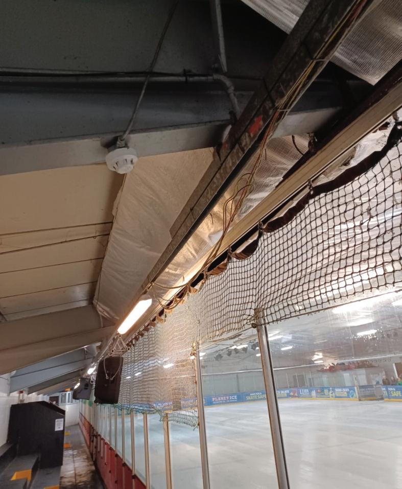
The trunk ing lid missing is now giving access to single insulated cables Coupled with the access to single insulated cables, there is now a potential collapse issue, as par t of the wiring has already star ted to give way and fall away from the trunk ing
Where the single insulated cables have begun collapsing, there could be damage to cables from their weight being pressed against the trunk ing lid securing points
A big issue here is also the danger to fire and emergenc y personnel from fur ther cable collapse in the event of a fire
Although the fire alarm sensor is not entirely within the remit of a BS 7671 periodic inspec tion, its supply cable is and appears to be unsuppor ted Being an unsuppor ted cable may cause strain on terminations and possible premature collapse. The sensor itself cannot be inspec ted or commented on from a BS 7671 perspec tive; however, an obser vation and note can be made on the EICR, highlighting to the Client or person ordering the work that a BS 5839 inspec tion may be prudent
The Observations, Regulation infringements and Codes applicable to this observation would be:
Terminations in connector block not taken into an adequate enclosure: Access to live parts
Connector block not adequately supported: strain on terminations
The re alarm sensor supply cable is unsupported, causing possible strain on terminations and risk of premature collapse
Trunking lid missing allowing the partial collapse of single insulated cables, and potentially endangering emergency services in the event of a re
134.1.1, 416.2.1, 526.5
134.1.1, 526.6
134.1.1, 521.10.202, 526. 6
134.1.1, 521.10.202, 651.2(V)
(Although the collapse of cables, per se, is not directly accessing live parts, the danger to the life of emergency service personnel in the event of a re, in my mind, allows the escalation from a C2 to a C1)
The A2:2022 18th Edition Codebreakers publication is priced at £22.00 (members) and £24.00 (non-members). It is available in both hard copy and digital versions
* Price is VAT exempt and excludes postage and packaging.
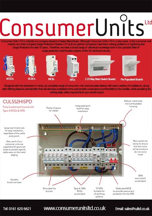

Having a positive cashflow indicates that your business has money left over after receiving payments on invoices and by paying all expenses incurred On the other hand, a negative cashflow often suggests that the company is in a d a n g e r o u s f i n a n c i a l p o s i t i o n a s i t m a y n o t be able to cover all associated running costs
Monitoring your cashflow position is crucial to the success of your business It enables you to meet your financial obligations and to better plan for the future Unfortunately, many businesses have trouble managing cashflow for a variety of reasons, as it’s usually the last thing on their mind at the end of a busy day Using a system to keep on top of your cashflow will help ensure your business is staying on track

Let’s look at five ways you can better manage your cashflow:
1. Have a financial plan
Setting a budget makes a huge difference Establishing a budget for the various costs over the year (such as marketing, supplies, transport, wages, etc ) can help to reduce on-the-fly decision-making and allows you to see if you have room in your finances to spend money in a certain area (or not).
2. Track your money
Avoid any nasty surprises by tracking your finances Knowing where your money is coming from and where it is going can help you identify where you can cut costs each month or where you may be underquoting without realising.
The best way to track your money and stay on top of business finances is with job management software, allowing you to gain real-time visibility of your business finances at a glance
3. Chase up invoices
Your positive cashflow will really suffer if clients aren’t being timely with payments
Aside from gaining a visual into your overall finances, job management software can encourage faster payments from customers by offering a variety of payment options.
A platform such as Fergus can also send automatic email or text alerts to remind customers of their overdue payments, all the while giving them the option to select their preferred way to pay. This helps you to get paid on time, speeding up your cash flow.
4. Plan ahead
Unfortunately, a lot of professionals end up with cashflow issues because they’re owed a lot of money from other construction firms who are lagging on their payments – not just clients and
customers One way you can save money, time and improve your cashflow is to talk to their suppliers prior to purchasing materials and negotiate their terms
Enquire about product discounts, whether you can return materials that are unused or no longer needed and whether you’re applicable for longer payment options
5. Forecast your cashflow
Cashflow forecasting involves estimating your future sales and expenses The aim is to help you predict your cashflow on a month-to-month basis or for the whole year Forecasting your cashflow can help to recession-proof your business because it will tell you if you’ll have enough money to run your business or expand it in the next 12 months
Cashflow forecasting manually, without help from job management software, often leaves businesses encountering shortcomings as they don’t have sufficient data to properly predict rapid changes
In essence, tracking cashflow and implementing a cashflow forecast helps to predict your future incomings and outgoings based on your current known costs and past revenue data
Q. I’m a sub-contractor and like to keep up-to-date with my qualifications and requirements However, I’m getting confused with all the claims by training providers stating they have a Level 3 qualification. When I look into it, it’s not an official qualification, but more CPD. Post-Grenfell, we all saw the ‘Setting the Bar’ government report recommending Level 2 or 3 qualifications for individuals for installers. What’s available, and how can we check if it really is a government-approved qualification?
You’ve picked a subject that drives me mad most days; only yesterday, a manufacturer put a comment on a post on LinkedIn where an individual was asking for a BS 5839-6 Qualification
The response he received was along the lines of: “Why don’t you do our qualification? We let you undertake the first few modules free of charge ” Big and bold was their company’s claim to a ‘City & Guilds Assured Qualification ’ To the non-educational specialist, it sounds like it fits the question
What does ‘City & Guilds Assured’ actually mean, and what is the ‘Assured Benchmark’?
The Assured Benchmark is a quality assurance framework which evaluates eight areas of programme design and delivery, called the Benchmark Standards, to confirm that an organisation has met the global quality standard set by City & Guilds and ILM

So, is that an official City & Guilds government-recognised qualification? No, it is that particular manufacturer’s
own qualification, however the training is approved to a certain standard by City & Guilds
Is that being a bit picky?
Although the standard of training may be excellent, it is not on the government ‘Office of Qualifications and Examinations Regulations’ register as an official qualification All City & Guilds official qualifications have the Ofqual logo
You can check every official qualification using the following web link: https://register.ofqual.gov.uk/. If the one you’ve been recommended is not on this register, employers and companies may not accept it as a qualification For example, the ECS card scheme will only accept official qualifications on the OFQUAL or SQA (Scottish Official Qualifications)
Is the manufacturer’s qualification useless?
Not at all It is good proof of ongoing CPD that all installers should undertake, as recommended post-Grenfell
How do you check if you’re getting an official qualification?
Either ask the question directly: “Is this qualification on the Ofqual Register” or you can check the company in question on the Ofqual register?
If you look at the government’s ‘Setting the Bar’ report, it asks for quite a few requirements and qualifications (one of them is highlighted here); so it is becoming more critical for individuals to have official qualifications and CPD
243. Recommendation: The industry
should adopt a framework for all the installer sectors working on in-scope buildings that can be applied to other project types. The framework will consist of:
● Accredited third-party certification of companies
● Level 2 or 3 qualifications for individuals
● A card scheme such as, but not limited to, the CSCS
● CPD refresher training and the maintenance of individual skills
● All installers have a core knowledge of fire safety in buildings – training to be standardised and made mandatory.
Ofqual has tightened its application process to stop just anyone from getting approval; an awarding body has to prove many things, including quality and financial stability For a qualification to be officially recognised in England and Wales, it will have the Ofqual logo, and in Scotland, it will have the SQA logo All Zzeus Training qualifications are by the awarding body EAL and are fully Ofqual registered As part of this you get a Zzeus CPD certificates plus an official Ofqual-approved qualification certificate, which is accepted for the Fire Operative ECS card
DO YOU HAVE A QUESTION YOU'D LIKE ANSWERED?
EMAIL YOUR QUERIES TO: TOM@ZZEUS.ORG.UK

‘DR. ZZEUS’ TOM BROOKES, md of zzeus training and CHAIRMAN OF THE FSA, ANSWERS YOUR QUESTIONS RELATED TO FIRE SAFETY COMPLIANCE.
When carrying out any new work, whether it is a brand-new building or an addition to an existing installation, BS 7671 requires an assessment of the proposed installation works
T h i s i n v o l v e s a n a s s e s s m e n t o f t h e g e n e r a l c h a r a c t e r i s t i c s o f t h e i n s t a l l a t i o n p r i o r t o s t a r t i n g d e s i g n w o r k W i t h o u t t h i s k n o w l e d g e a n d u n d e r s t a n d i n g o f t h e r e q u i r e m e n t s f o r t h e i n s t a l l a t i o n , t h e p r o p o s e d w o r k w i l l m o r e t h a n l i ke l y f a i l t o m e e t t h e e x p e c t a t i o n s o f t h e c l i e n t I f a n i n s t a l l a t i o n h a s n o t b e e n d e s i g n e d t o t a ke i n t o a c c o u n t a n y c o n t r i b u t i n g f a c t o r s r e g a r d i n g t h e u s e, l o a d i n g o r o p e r a t i o n a l d e m a n d s , a l l m a n n e r s o f p r o b l e m s c a n a r i s e
In this article, I’ll cover this process and provide a reminder of the assessment requirements for any new electrical work
BS 7671 Part One, Chapter 11, lays out the scope for electrical installations The first step is to determine if the proposed design meets the requirements within Regulations 110 1 1 to 110 1 3 This lists each of the type of electrical installations where BS 7671 applies and includes those details covering a wide range of electrical work that electrical installers will normally be involved in designing Regulation 110.2 provides the exclusions from the scope of BS 7671 for which other requirements would have to be considered when designing electrical work in these areas
O n c e t h e t y p e o f p r e m i s e s o r l o c a t i o n s have been established, we can move onto the other considerations that will have to be included in the design
N e w e l e c t r i c a l i n s t a l l a t i o n s h a v e a v e r y straightforward assessment process, since the building or premises has been created, the use has been identified, and all of the work will be completed with new products and materials
Within Chapter 13, Regulation 131 1 provides the requirements that the essential part of the design is to ensure the safety of persons, livestock and property from any dangers which may arise from the reasonable use of the electrical installation.
In the following list, we
outline the areas within an electrical installation where the risk of injury may arise:

● Shock currents
● Excessive temperatures
● Ignition of a potentially explosiveatmosphere
● Undervoltage
● Overvoltage
● Electromagnetic disturbances
● Mechanical movement of electrically actuated equipment
● Interruptions of power supplies and/orsafety services
● Arcing or burning
In the case of existing installations, where additions and alterations are proposed, the designer has extra considerations to make, especially if the installed equipment and services have not been subject to full scrutiny during the initial or subsequent work
If the original design details are not available to determine the use and loading requirements for which the existing installation was intended to be used, it does place additional responsibility on the new designer to attempt to interpret the original designer’s intent
Regardless of the installation being new or existing, the designer has to carry out the assessment of the general characteristics of the installation
BS 7671, Chapter 30, provides the following installation characteristics to be considered:
● Purpose(s) for which it is intended to be used;
● General structure and supplies;
● Any external influences;
● Compatibility of its associated equipment;
● Maintainability;
● All recognised safety services; and
● Assessment for continuity of service
Based on the aforementioned details, it is vital to assess what the installation will be used for before you commence the design process, to ensure there are no inherent problems resulting from excessive loading or inadequate protection for the circuits
Throughout Chapter 31, the term maximum demand is used, and in particular, Regulation 311 1 states how the maximum demand shall be determined It further expands on this where diversity may be considered for the entire installation or part of the installation
There is a requirement in Regulation 641 2 that an assessment of the electrical installation is provided to the person carrying out the inspection and testing, which includes the items mentioned previously regarding the installation’s safety and general characteristics.
The Electrical Installation Certificate (EIC) has a box that requires information to be inserted for the maximum demand either in kVA or Amps It is often listed on the EIC as a figure, but there is very seldom any calculation provided to show how that figure has been determined, or if diversity has been used to calculate.
In some cases, the figure recorded on the EIC may refer to the rating of the service cut-out fuse
So, how do we assess this maximum demand and take into account diversity for an electrical installation?
A typical example of this can be the increased number of electric vehicle charge points being installed, and this type of electrical installation requires additional notification to the distributor In reality, all installations that can increase loading that affects the distributor’s or supplier’s equipment may also require notification
For EVCP installations there is a requirement to assess the maximum demand of an existing installation. The maximum demand is the connected load, including any allowance made for diversity, which is referred to as the maximum anticipated load or the actual load The existing maximum demand must be reviewed as the EVCP electrical load cannot take diversity into account.
To determine the maximum demand of an installation using diversity, Fig 1 shows an example assuming the circuits of a 10-way consumer unit with a main switch rated at 100 A It has four spare ways and supplies six circuits as follows:
One 40 A cooker circuit
Two 32 A ring final circuits
One 16 A immersion heater
Two 6 A lighting circuits
The calculation in Fig 1 shows there is no allowance for diversity, therefore the
EVCP full load shall be used, which is 30 43 A
The inclusion of the EVCP creates a new maximum demand of 76.8 + 30.4 = 107.2.
Therefore, the new maximum demand exceeds the current rating of the consumer unit This arrangement is unacceptable and would require an application to the DNO for assessment of the service intake equipment.

In order to reduce the loading, load curtailment would be an option, which can be used to determine the maximum demand
As you can see in the example in Fig 1, detailed information will be required on the electrical equipment installed within the premises in order to determine the maximum demand figure and insert this figure into the EIC
By carrying out the required assessment of the electrical installation, the designer will have the necessary information to commence the design, arrange any additional work required to increase the supply to the premises, and then install the proposed work This will ensure the client has an electrical installation that will meet their operational and safety requirements
40+ [0.4 x [32+32+16+6+6]] = 76.8 A
Whilst it’s an employer’s legal responsibility to ensure that staff have the right level of protection and training against risks on-site, employees have a personal responsibility to be aware of risks and potential injuries to ensure adequate protection for themselves, their safety and wellbeing
Depending on the job task to be performed, PPE for electricians generally includes safety glasses, face shields, hard hats, safety shoes, insulating (rubber) gloves and flame-resistant clothing.
In terms of clothing, there’s a big difference between conventional workwear and specialist protective wear

Over the years, workwear has evolved to make the working day more comfortable and efficient, with built-in functionality for
tools and fixings, as well as protection against cold, rain and the effects of warm weather
Protective wear, which can have one or more CE (European Conformity) marks, has been designed and developed to protect the wearer from serious risks such as heat, flames, electric arcs and hazardous chemicals.
In order to meet the protective requirements of a specific risk area, protective wear is divided into three categories – the higher the category number, the higher the level of protection.
Category I covers exposure to minimal risks, and for this category there are CE standards such as EN 343 (rain protection) and EN 14058 (cold protection)
Category II includes exposure to medium risks, for instance EN 20471 for high visibility clothing.
Category III covers exposure to serious risks, which include major hazards such as electric arcs and molten metal splashes or liquid chemicals
What protection do electricians need?
To be able to properly identify what protection you need, you have to know what risks you, your employees or your workmates face
Never assume that a Category I garment will protect against the more serious hazards and risks defined in Category III It won’t, and you’ll be putting yourself at serious risk if you think it will.
That means understanding the hazards and risks of a specific electrician’s working environment or knowing the risk level before you start work
That risk assessment and the determination of the ‘calorie levels’ required in the clothing needed has to be carried out by the company buying the
clothing. Importantly, each working situation will have its own required minimum protection, depending on the risk situation
How do I know the protection level of my outfit?
It all starts with having working clothes with the appropriate CE mark for the specific risk environment.
In work locations that involve a risk of electric arcing, you must also ensure your clothing offers a level of protection that corresponds to the risk level – Category III
You do this by adding up the total number of ‘calories’ of all the layers of your outfit and it’s important to remember that high-risk environments require that all the clothes you wear, including underwear and base layers, provide protection against heat and flames
What is a ‘calorie’ in the context of PPE?

In PPE terms, calories are used to define the protection level of a fabric, an item of clothing or the system of materials/garments
When an electric arc is triggered, different types of energy and risk factors are created, such as arc power, arc energy and incident energy, all of which are measured in calories This is why calories per square centimetre (cal/cm2) has become the unit used to measure a fabric’s or garment’s level of protection
What sort of electric arc risks do electricians have to deal with?
Arcs due to electrical faults can cause severe injuries and damage such as thermal injury, serious burns, electric shock, noise, UV emissions, pressure and shrapnel, as well as toxic exposure and the impact of physical and mental shock.

A burn to the skin or other tissue is caused by heat or hot substances in a solid, liquid or gaseous state They can cause tissue damage to various degrees, depending on the nature, intensity and duration of the damage Burns are classified into four types:
First-degree – results in damage to the epidermis (outermost layer of the skin), which normally heals in a couple of days
Second-degree – damages the dermis (thick layer of living tissue below the epidermis), usually causing skin blisters and major inflammation.
Third-degree – causes total damage to skin/tissue and is characterised by hard, white skin resembling parchment In a full-thickness skin injury, sensory receptors in the tissue are damaged, meaning no pain will be felt in the damaged area.
Fourth-degree – extends through the entire skin into underlying fat, muscle and bone and, as a result, the skin is black and charred with dead tissue
The injury area is defined as the TBSA (Total Burn Surface Area) percentage, which expresses the size of the burn as a percentage of total body area For instance an arm is approximately 9%, and a leg 18%
Based on independent tests and reports coupled with our years of experience, we recommend that you should never wear garments that offer total protection of less than 11 calories/cm2 if you are going to work in or near a high-risk environment
This calorie level doesn’t provide total protection, but should be seen as a minimum level. Different jobs require
different levels of protection, and the higher the calorie level your clothes (or outfit) have, the better protection you get That’s why you should know the risk level before you enter a specific risk environment, and wear appropriate clothing
Wear layers to increase your protection
One of the best ways to improve your level of protection is to wear layers – base-, mid- and top-layers A fundamental requirement is of course that all the garments are certified and flame retardant
The main benefit of wearing layers is that the air gap formed between different garments provides increased protection. There is no general rating for how much increased protection the air gap between layers provides We have, however, conducted a number of tests that show that the air gap increases protection by more than 5 calories/cm2.
The calorie level of the extra protection depends on a variety of factors, such as fabric structure, thickness and construction – and for a precise value, combined tests on each layer must be performed
• Powerful LED outputs with robust construction
• Innovative features, including motion sensors and USB charging capability for user convenience
• Comprehensive range, from compact head torches to mains powered tripods
See the full range at: www.luceco-worklights.com


Unfortunately, there have been incidents where failure to use safe isolation procedures has resulted in the needless loss of life Electrical Safety First, in association with other industry bodies such as SELECT, produced a guidance document that covers best practice for safe isolation (Best Practice Guide 2 Issue 3, 2015) This includes guidance on proving isolated equipment or circuits are dead using suitable test lamps and voltage detectors Using the right equipment is one of the most important parts of the procedure, as failure to do so can result in a circuit inadvertently remaining live, resulting in injury or death.
What equipment is required for safe isolation?
Best Practice Guide 2 advises that, where using a main switch or distribution board switch disconnector for isolation purposes;

“The point of isolation should be locked off using a unique key or combination retained by the person carrying out the work or the appointed person, and a caution notice attached to the point of isolation Where more than one operative is working on circuits supplied from an isolated distribution board, a multi-lock hasp can be used to prevent operation ” Locking off kits are available to ensure you have all the necessary equipment to lock out the circuit being worked on at hand There are a number of locking off kits available on the market, however, a basic kit should include the following:
● Selection of MCB and breaker locks,
● Padlock with a unique key or combination,
● Hasp for when more than one person is working on a system,
● Lock out tags and warning labels
Note that the padlock must have a unique key or combination held by the person
Safe isolation procedures are necessary to ensure that workers on-site are not exposed to danger when working on or near live electrical systems, as Martindale Electric’s Managing Director, Steve Dunning, explains.
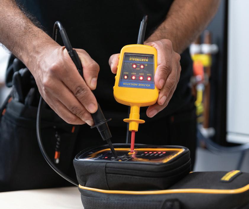
carrying out the work to prevent anyone else from removing the lock and inadvertently activating the circuit Most combination padlocks have a default setting of zeroes If this type of lock is being used, it’s essential to ensure the combination has been changed prior to use
A unique key lock provides the safest solution Once the breaker has been locked off correctly, a warning tag should be attached to clearly identify that the circuit has been locked off and is currently being worked on
Locking off the circuit is just one part of the procedure Next, verifying that the circuit is dead before carrying out any work is essential. Circuits are frequently mislabelled so there is no certainty that the correct circuit is locked off You should use a dedicated voltage indicator and a proving unit to do this
The guidance makes several points in regard to the use of voltage indicators to prove dead, some of the key ones are:
“Following isolation of equipment or
circuits and before starting work it should be proved that the parts to work on, and those nearby, are dead It should never be assumed that equipment is dead because a particular isolation device has been placed in the OFF position ”
So, it is not enough to simply lock off the breaker and assume that the circuit is now dead There are recorded instances where neutrals are “borrowed” and while this is not permitted in BS 7671:2018 Requirements for Electrical Installations, it is not uncommon In this instance, although a particular circuit may be locked off, the neutral conductor can become live if an energised load on another circuit is connected to it
Best Practice Guide 2 advises that you should use a dedicated voltage indicator and a proving unit when carrying out this procedure Equipment must comply with BS EN61243 which, since May 2013, prohibits the use of fuses in two pole voltage indicators
The list of suitable equipment includes test lamps, such as the Drummond MTL10 or MTL20, or a two-pole voltage indicator, such as the Martindale VI13800 or VI-15000 which include a high wattage resistor in the probe to limit the current in the event of damage to the cable
It is important to note that the voltage indicator MUST be able to work without the need for a battery. If you’re using a

device that needs a battery in order to work and the battery is flat, you will not be able to prove if the circuit is dead!
The procedure for proving dead is to take the voltage indicator and check it against a known source, such as a proving unit, then test the circuit, before testing the voltage indicator against the known source again to prove the tester hasn’t failed during testing
Whilst you can use a known live source to test your voltage indicator, we recommend using a dedicated proving unit The reason for this is that the known live source will only light some of the LEDs on the tester, whereas a proving unit will ensure that all LEDs on all ranges are working, again safeguarding against incorrect readings due to a faulty LED In addition, there’s not always a live source nearby and a dedicated proving unit is safer.
Why can’t I use a multimeter or non-contact voltage detector to prove dead?
Firstly, the use of multimeters or non-contact voltage detectors is advised against in the HSE guidance and the use of these has resulted in accidents in the past The reason that a multimeter isn’t suitable is that it is all too easy to select the wrong range In addition, the multimeter relies on battery power to function, thus there is a high risk of making a false “dead” reading on a live circuit. Non-contact voltage detectors also
5 fail-proof steps to safe isolation
APPROVED KIT
Your equipment should meet all legal safety standards (BS EN 61243-3) and you should check this before you begin work.
Identify the point of isolation and lock it off Remember to place warning tags on the equipment
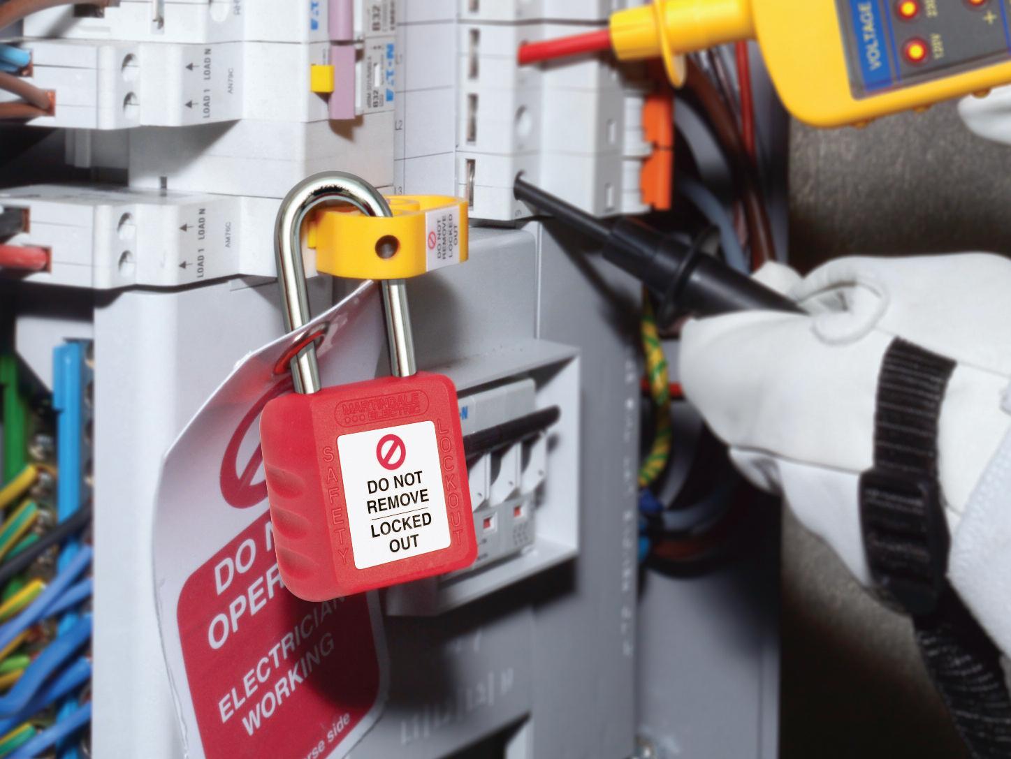
Test your Voltage Indicator against the proving unit to make sure it’s working properly.
Use your Voltage Indicator to confirm there are no dangerous voltages in the circuit you are about to work on
ALIVE A L I V E
Finally, prove and re-test the Voltage Indicator against the proving unit to ensure it’s still working When this is done, you are ready to start working on the circuit with confidence
require a battery in order to work and are often sensitive to other signals, such as static electricity It’s also not possible to prove they are working correctly with a standard proving unit. Whilst these units can be used to detect live cables, they can’t reliably be used to prove dead
ISOLATION AND ELECTRICAL TEST EQUIPMENT AT: WWW.RDR.LINK/EAQ017

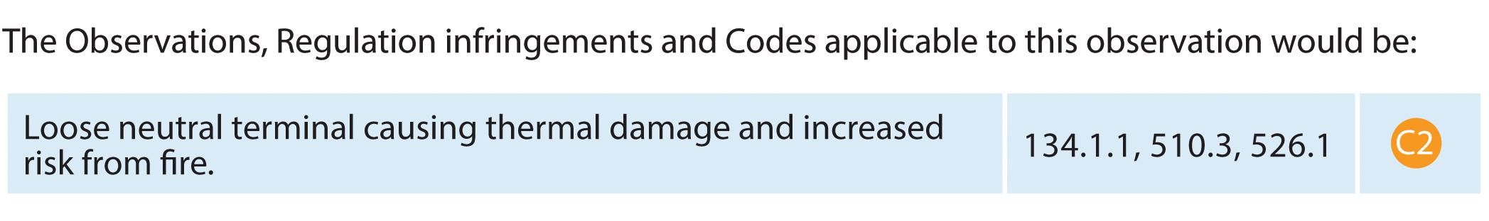
A few years ago, a big emphasis was put on the correct torque requirements for electrical connections, especially those within switchgear, such as consumer units (CUs) and distribution boards (DBs) The drive to highlight the issues caused by incorrectly torqued connectors, both too tight and too loose, was well justified when we see this type of obser vation on an EICR.
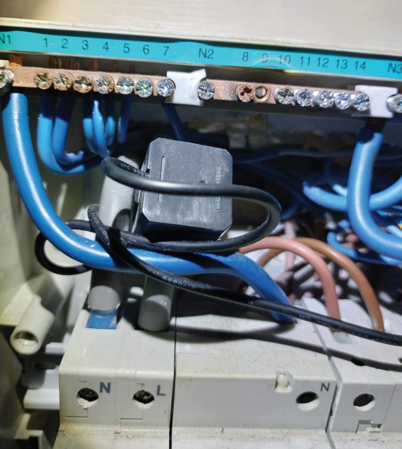
I t is becoming quite common to see, possibly because more EICRs are being carried out, and hopefully, highlighting these faults early can help to reduce the risk of fire Also, remember that this is a plastic CU, which isn’t inherently a problem but does back up the industr y ’s push to ensure connectors are adequately torqued.
A secondar y problem, which is not an issue here, is that access to CUs is vital Where CUs are blocked in or cannot have their front covers removed or connections torque checked, there is an increased risk of fire from poorly torqued or loose connections, which must be coded accordingly
With the thermal damage in this obser vation caught at the right time, the inspector may want to advise that the neutral bars are replaced, as they appear to be star ting to erode due to heat damage. Either way, the loose terminal can only be coded one way
Need help with cracking those all-impor tant EICR codes? Ever y month the technical team at NAPIT will be studying your latest ‘Caught on Camera’ photos and offering advice on the next steps, should you find a similar installation. If you want the team at NAPIT to help crack your codes then send your pic tures through to us at: pe@hamer ville.co.uk
One of the biggest issues we face in our industr y is either a lack of competence or a lack of correct competence We can all be competent in one aspect of work but lack training or competence in another area.
I t ’s vital that you ensure that you and your employees are competent to carr y out the work you under take as a business I t ’s easy to accept work , but underestimating the competence required to fit the equipment required can prove ver y dangerous Likewise, if you accept work and assume your employees have the same competence as you, or if you think they do, you are ask ing for trouble without mak ing sure
The three -phase fused switched isolator is, or should be, a pretty simple and straightfor ward item to install That said, if you are unfamiliar with it or similar equipment, it can be a daunting task and will lead to serious problems when installed incorrec tly If installed correc tly, when the isolator is turned off, the line conduc tors are separated from the fuse holding assembly so that they can be replaced, removed or checked for routine maintenance.
The installation in the photo shows both the supply and load conduc tors connec ted direc tly to the fuse -holding assembly and the neutral link bar This has two effec ts: firstly, the switch isn’t operating anything, as the switch sec tion is at the rear, which is
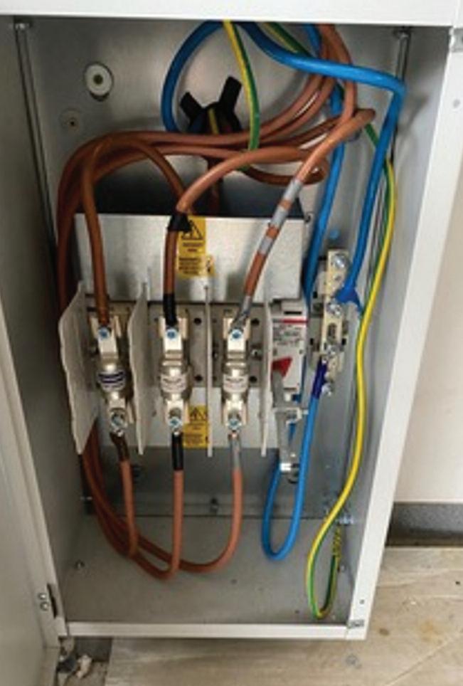
where the supply and/or load conduc tors should be connected, so in this configuration, the fuse assembly is constantly live regardless of the switch’s position.
This leads to the second issue: there is access to live par ts when we expec t them to be isolated, which means the upstream device will need to be isolated to allow work to be carried out. Tak ing the need to check for dead each time we touch any conduc tors, it would only take a moment ’s distrac tion to forget, and the consequences could be fatal.
When coding this, even though it ’s secure and only accessible by a competent person, it has a real potential for danger if you think you’ve isolated it, but it isn’t. These devices come with installation instruc tions, which would have pointed out the correc t way to install, and these clearly haven’t been followed.
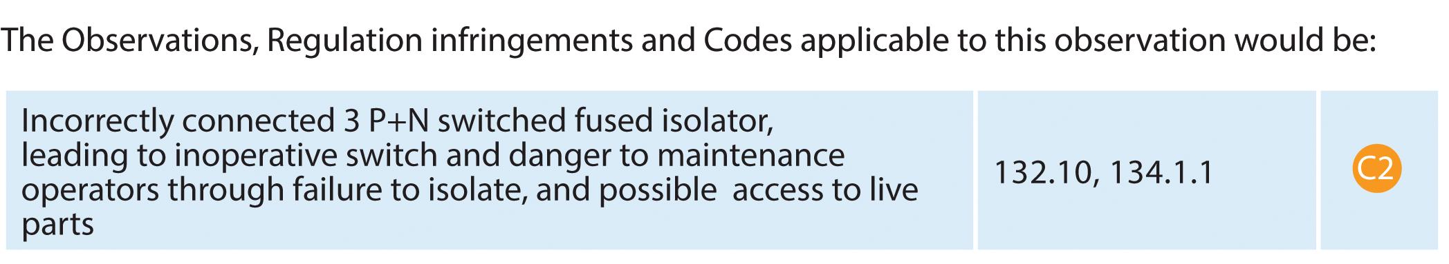
“The installation in the photo shows both the supply and load conductors connected directly to the fuse-holding assembly and neutral link bar. This has two effects...”

This article from NICEIC will look at the environmental factors that should be considered when selecting, installing and using electrical supplies and equipment on a construction site.


Most construction sites require electrical supplies to provide power for tools, equipment, lighting, and the like The adverse environmental conditions typically found on construction sites inherently increase:
● the risk of damage occurring to wiring systems, electrical equipment, and
● the shock risk
These increased risks need to be managed in order to comply with legislative requirements for construction site safety and for the use of electricity
The degree of risk and likelihood of damage to installed equipment, and as a result the persons using it, vary across a typical construction site. Therefore, the
supply to electrical equipment must be suitable for the environment in which it is to be used, taking into account that electrical equipment will be operated by ordinary persons (as defined in Part 2 of BS 7671)
With the exception of the installations in administrative locations such as offices, meeting rooms and site welfare areas, where the general requirements of Parts 1 to 6 apply (704 1 1), electrical equipment used on a construction site must be suitable for the harsh conditions expected for the environment (704 512 2), including:
● contact with corrosive substances,
● ingress of liquids or dust and other solids,
● wear and tear caused in use by impact, abrasion, tension and flexing,
● extreme temperature fluctuations,
● damage by movement of vehicles and structures.
Measures to minimise likely detrimental effects
Wherever possible, electrical equipment and wiring systems should be located in a manner that minimises the chance of exposure to corrosive or polluting substances such as water, cement and/or plaster. One of the most effective ways of achieving this is by avoiding the installation of cables and/or equipment in locations where such exposure is likely
However, where this is not possible, parts of the wiring system likely to be exposed to these detrimental substances should be suitably protected by additional mechanical protection or constructed of corrosion resistant materials (522 5 1)
Work on construction sites generally takes place outdoors and in all weathers However, section 704 of BS 7671 does not state a minimum acceptable degree of ingress protection against either water
other liquids or foreign solid bodies, therefore the general rules given in Section 522 of BS 7671 will apply. For example, where water collects inside a wiring system, provision should be made for its escape, typically at the lower points within an accessory or containment system (522 3 2)
However, Section 704 does specify that:
All assemblies for the distribution of electricity on-site shall be in compliance with the requirements of BS EN 61439-4 (704 511 1) Clause 8 2 2 of this standard requires a minimum degree of ingress protection of:
● IP44 when all doors are closed and all cover plates and removable panels are in place
● IP21 provided that the door can be closed under all conditions of use, or IP44 at the operating face where the door cannot be closed
Any plug or socket-outlet with a rated current of 16 A up to 125 A should comply with the requirements of BS EN 60309-2 Similarly, plug and socket-outlets with a rated current exceeding 125 A up to 800 A, and where interchangeability is not required, should comply the requirements of BS EN 60309-1 (704 511 1)
To avoid damage, cables should not be installed across site roadways or access ways used for transport and mobile plant Where this is unavoidable, adequate mechanical protection shall be provided to minimise damage or potential deterioration caused by vehicles and the movement of building materials on-site (704 522 8 101), see Fig 2
Alternatively, where it is necessary to route cables underground in such locations exposed to site traffic, cables should be laid in ducts at a depth of at least 0 6 m below finished ground level and a cable marker should be installed at each end of each road crossing (Clause 7.1.5 of BS 7375).
Additionally, cables run on the surface
and/or overhead should be protected against mechanical damage, whilst taking into account the environment and likely activities at the construction site (704 522 8 101)

As with any other type of installation, the general rules of Chapters 51 and 52 of BS 7671 relating to effective selection and erection of equipment apply
Where the protective measure of electrical separation of circuits is used in such locations, including for circuits supplying a socket-outlet with a rated current up to and including 32 A, and for any other circuit supplying hand-held electrical equipment, the requirements of Section 413 must be met (704 410 3 10) In particular, any flexible cables should remain visible throughout any part of their length liable to mechanical damage (413 3 4)
Only low temperature 3182/3/4/5A thermoplastic cable complying with BS 6004 or other equivalent flexible cable may be used for a reduced low voltage system (704 522 8 11)
Electrical equipment installed on a construction site must be suitable for the temperatures to which it might reasonably be expected to be exposed Temperatures can fluctuate widely, especially when undertaking work in an open structure (Fig 1), leaving equipment vulnerable and exposed to the environmental elements over a range of seasons
As required by Regulation 522 1 2, cables and associated wiring accessories should not be installed or manipulated outside of the boundary temperatures specified in the relevant product standard or in manufacturers’ data.
Table C 2 in Annex C of BS 6004 states that type 3182/3/4/5A round flexible cables are suitable for intermittent and temporary periods of short duration outdoor use, are resistant to frequent flexing and torsion, and may be both installed and handled at temperatures as low as -25 °C
However Table C 3 of that standard clarifies that type 3182/3/4/5A cables are not suitable for outdoor use at voltages greater than 110 V For applications exceeding reduced low voltage (RLV), flexible cable complying with H07RN-F (BS EN 50525-2-21) type or equivalent heavy duty flexible cable should be used (704 522 8 11)
Similarly, all flexible cables that are subject to movement on construction sites shall be H07RN-F type or equivalent (704.522.8.101). Such cables are generally
“To avoid damage, cables should not be installed across site roadways or access ways used for transport and mobile plant.”
manufactured with a polychloroprene sheath, giving them the capacity to resist abrasion and water They have an operating temperature in the region of -15 °C to +60 °C when used in applications such as construction sites where frequent mounting and flexing is likely
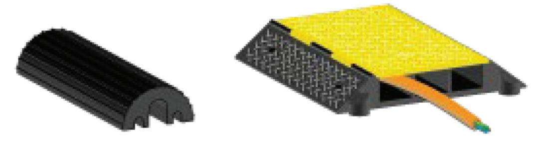
The flexible leads supplying power tools and other portable equipment on-site are particularly vulnerable to damage As such, they should be checked before use to confirm their continued adequacy As with any other cables, additional protection should be provided across routes where personnel or vehicular movement is expected
Regular inspection and testing is essential to confirm the continued suitability of the temporary electrical installation, including the tools and equipment connected to it

Clause 9 of BS 7375 recommends that:
Fixed installations, whether operating at 400/230 V or 110 V RLV, should be inspected and tested at least every three months but more frequently where necessary Records should be kept of any test results obtained for future reference when determining whether deterioration has taken place
Movable installations should be inspected
and tested more frequently, typically weekly, or more often where conditions require it RCDs should be subjected to testing using an RCD test instrument every three months and it should be confirmed that pressing the integral test button causes the RCD to operate prior to operation of the equipment it protects.
A construction site can be a harsh environment for an electrical installation So that the installation may be used safely by electrically unskilled persons, care must be taken when selecting equipment for use in such environments Any chosen equipment must be suitably resilient to the potential sources of damage likely to be present, either by its construction or through the application of additional protective measures.

QDo we have to install an additional earth electrode for all TN systems now Amendment 2 is in force?
Within BS 7671:2018+A2:2022, Regulation 411 4 2 provides requirements regarding the connection of exposed-conductive-parts of the installation to the main earth terminal of the installation This is not a new requirement and has always been part of BS 7671 to provide a reliable connection to the earthing system
The new wording within Regulation 411 4 2 is the final paragraph, where it introduces a recommendation that an additional connection to Earth by means of an earth electrode to the main earthing terminal See Fig 1 for an example of an additional earth electrode
The idea of adding an additional connection to Earth is to supplement the earthing system of the distributor in case
of failure in the ageing network This recommendation contradicts the advice given in Regulation 411.4.1, which advises that conditions external to the installation are the distributor’s responsibility
The important word here is ‘recommendation’, as such, it is not a requirement, and there is no requirement to install an earth electrode for every TN system in a client’s premises
Therefore, the answer would be no, you do not have to install an additional earth electrode If you were to decide to follow the recommendation to install such an electrode, there are several things to consider:
● Type of earth electrode
● Location
● Connection and termination enclosure
● Verification of the resistance
● Identification
● Certification
The type of earth electrode will be selected in accordance with Regulation 542.2. Any location for an earth electrode must be selected taking into account any adjacent surface and buried service pipes or cables
A ground scan of the prospective additional earth electrode location should be carried out to ensure there will be no damage to any other equipment buried in the ground The earthing conductor connected to the earth electrode should be enclosed, protected from the effects of corrosion and securely terminated
The same test requirements for confirming the resistance of the earth electrode should be carried out on the installation earth electrode and recorded on the electrical installation certificate
Identification of the electrode termination shall be marked with the ‘Safety Electrical Earth Connection Do Not Remove’ label. Further identification at the main earth terminal should be provided to ensure the user and anyone working on the installation in future are aware of additional earth electrodes
Within the electrical installation certificate, the details of the additional earth electrode should be recorded separately to the installation earth electrode as this refers to a TT system of earthing only
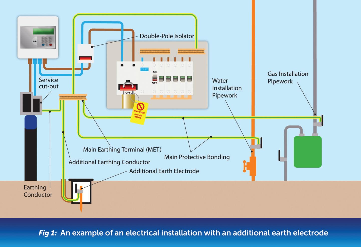
If you are an electrician and are looking to develop your skills and increase the range of work you are competent to undertake, an electrical installation design course with NAPIT Training can be of immense benefit

Marketing is all about the way you communicate to your target market, who you are and what you have to offer It’s also communications with your team so they know what’s going on Marketing is the right arm of the human body use to describe the Bright 7 Sect System The word I use to give a explanation of the five levels of marketing is L E A D S
Ultimately, this is what marketing is all about –generating leads and opportunities for your business and getting a return on your investment (ROI) from you marketing plan We build th using the Market, Message & M Methodology, which is as follow

First determine who you want to target This is sometimes called your target market, avatar, target audience or persona You market to them by understanding where they are (industries, geography), what they need (challenges and problems of that market), what they do, where they go, what they read, their hobbies and interests, where they hang out, etc
When you know who your avatar is, you can start to define your message You
need to grab their attention in this busy world by creating a language that speaks to them personally Content that is interesting to them You need to push their buttons so that they take action.
It’s when people are worried, scared or needing something that they most often take action If you have a toothache, you go to the dentist This is why it’s referred to as a pain point. When researching your avatar, drill down into their pains and also understand their desires to create a powerful message

When you have really defined your message, it’s time to look at media –both online and offline Offline marketing examples include: exhibitions/networking events, flyers/folders/brochures/direct mail, telemarketing and
aper/magazine articles and tising
Online marketing examples clude: Website/SEO and pay per click, Google AdWords, email contact lists, LinkedIn and Facebook pages or groups, Instagram and YouTube
THE SECOND LETTER IS E, WHICH STANDS FOR EVERYWHERE
You want your brand to be seen verywhere across both online d offline media and you want it with consistency and continuity message Ultimately it is about sure your message is in as many different places as you can get it You want to be driving this message at specific areas to give you the best response
The software applications you use in your marketing are based on the type of marketing you want to do. Used correctly, the right software can help you manage your database and email marketing becoming (what is known as) a CRM (Customer Relationship Management) system
emerson patton, foundER of bright business advice and creator of THE ‘bright 7-sector orbit’ business model, shares his advice for building a better business
The CRM is so important and yet most people aren’t using it properly To assist contractor businesses, we use our own ‘Bright Marketing Machine’ CRM software to help them drive leads into their sales funnel/pipeline (usually a specific webpage) from email/text message marketing, social media posts and pre-recoded video content

The leads are nurtured down the business’ funnel/pipeline using emails/texts and phone calls/voice messaging etc., keeping track of all the notes and messages and visually seeing how far along they are in the sales process When the time is right after surveying and quoting you’re then in a position to close and win work more easily
The software also allows you to store documents and useful downloads (such as brochures or job specification details) which you can send to your team or customers at the touch of a button
With a full pipeline you
won’t be chasing around hoping to win some jobs Instead you’ll be lining them up and cherry-picking the work you want!
THE NEXT LETTER IN L.E.A.D.S IS D, WHICH STANDS FOR DO’ER
Do you need a ‘do’er? An individual in your team who enjoys, and has a passion for, marketing Someone who is not just going to talk about it but will actually get it done by creating, writing and posting on social media, updating your website, creating case study content for your blogs etc In turn, this will free up you time for your expertise to be applied to other areas of your business where it may be better suited
THE LAST LETTER IS S, WHICH STANDS FOR SUPERSTAR!
This is essentially the Marketing Director of your company – someone who can be a genius in your business Their job is to pull all the marketing strands together into a plan, devise the strategies and tactics you will use to generate leads for your products and services, and decide on which markets to go into They can help to create and bring to life all the messages you want associated with your business, in every way that you communicate it to your audience
“Do you need a do’er? An individual in your team who enjoys, and has a passon for, marketing. Someone who is not just going to talk about it, but will actually get it done...”
Replacing a consumer unit is classed as an alteration to the electrical installation
Alterations and additions are categorised as ‘new work’ and all new work on an electrical installation must be designed, installed, and verified in accordance with the current edition of BS 7671 (designers and installers should refer to BS 7671 and other relevant documents for full requirements) The current edition is BS 7671 2018 including Amendment 2
Scope of new work
In some circumstances the scope of the new work for such a task may be limited to the installation of a new consumer unit and new circuit protection devices
However, it may be necessary to carry out other new work in order to meet all of the required safety levels, especially if C1 conditions have been observed from an inspection of the installation
New consumer unit and devices
In situations that require a consumer unit to be replaced the new consumer unit should comply with BS EN 61439-3 and Regulation 421 1 201 which requires the consumer unit to have its enclosure manufactured from non-combustible material or be enclosed in a cabinet made of non-combustible material
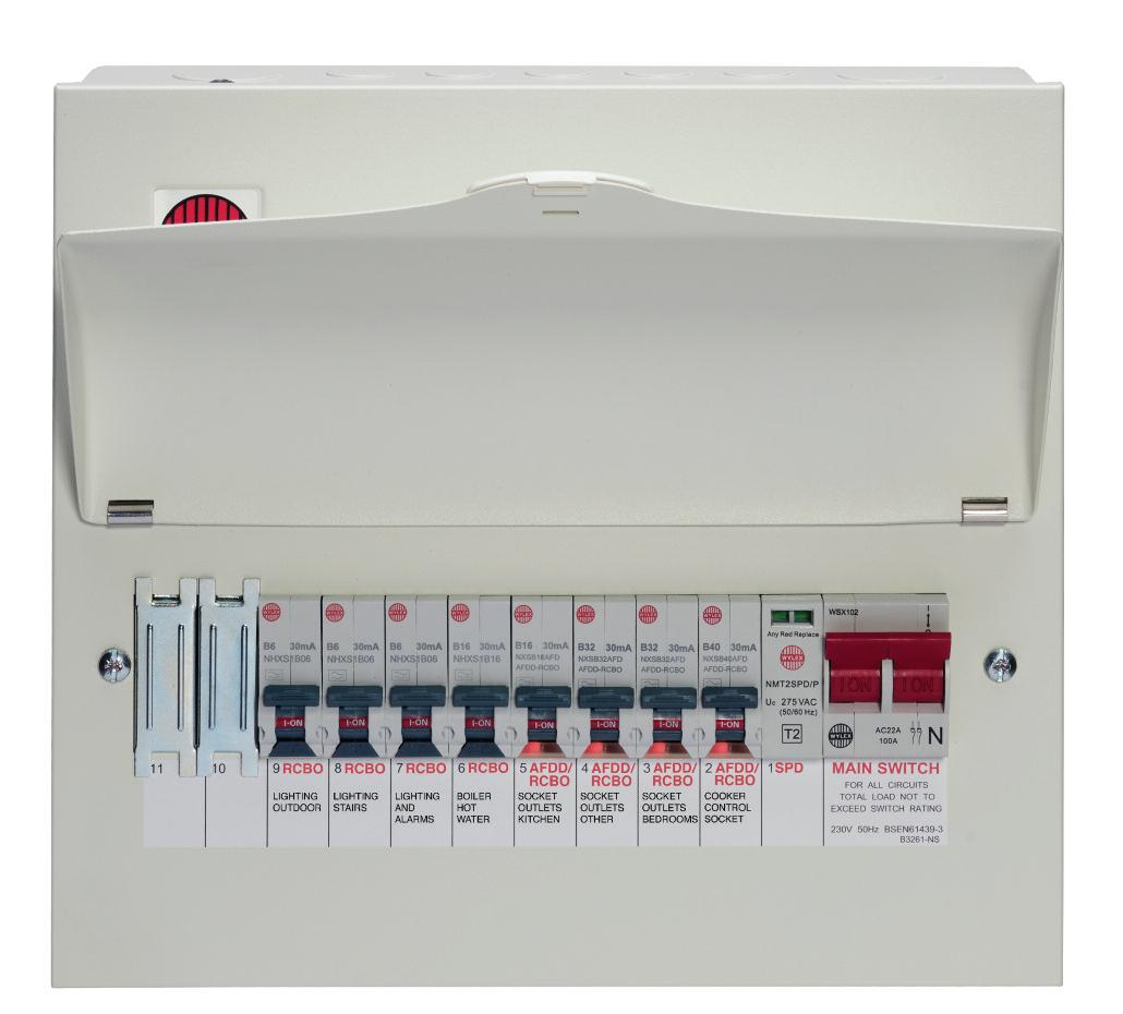
Consumer units that meet the above criteria are designed to incorporate
protective devices such as MCBs, RCBOs, AFDDs, and SPDs that the wiring regulations require These devices provide much higher levels of protection and electrical safety than old fashioned fuses ever could
Where the existing wiring is deemed to be suitable to be connected to the new consumer unit there are some specific requirements within the Wiring Regulations that will determine which type of protective device is required on each circuit
Additional protection by use of 30mA RCD is required on cables buried/concealed in walls and partitions if those cables aren’t installed in/with earthed metallic coverings Therefore, where the existing final circuits are installed in this way additional protection by a 30mA RCD is required (see Regulations 522.6.202, 522.6.203 & 522.6.204).
Additional protection by use of 30mA RCD is required for each circuit that passes through or serves equipment in locations containing a bath or shower (see Regulation 701 411 3 3)
Additional protection by use of a 30mA RCD is required for users of socket outlets (up to 32A rating) in all locations where they’re liable to be used by persons of BA1, BA2 & BA3 capability i.e. ordinary persons, children, and disabled persons No exceptions are permitted (see Regulation 411 3 3) AFDDs are required for single-phase AC final circuits supplying socket-outlets (up to 32A rating) in high risk residential buildings, homes in multiple occupation, care homes and student accommodation (see Regulation 421 1 7) Note: Electrium AFDDs include an integral Type A 30mA RCBO and can provide additional protection as well as arc fault protection.
SPDs should be installed in new consumer units unless the owner of the installation declares otherwise An owner who declares that overvoltage protection is not required accepts all risks, consequences, and losses (see Regulation 443.4.1).
Other considerations also apply Catering for modern demands on an electrical installation means taking account of the connected equipment, and portable devices These will no doubt bring DC influences and PE currents into consideration for the installer.
For example, Regulation 531 3 2 requires protective conductor currents (standing earth leakage not due to a fault) to be no more than 9mA for a 30mA device to help to avoid unwanted tripping, but that can’t be achieved if several circuits are protected by one RCD device There are also the requirements of Chapter 31 and Regulation 314.1 to consider. This requires the installer to:
● reduce the possibility of unwanted tripping of RCDs,
● avoid danger and minimize inconvenience in the event of a single fault,
● take account of hazards that may arise from the failure of a single circuit,
● facilitate safe inspection, testing and maintenance

Therefore, wherever additional protection by a 30mA device is required each circuit should be served by an individual Type A 30mA RCBO to fully meet the requirements of the current edition of the Wiring Regulations.
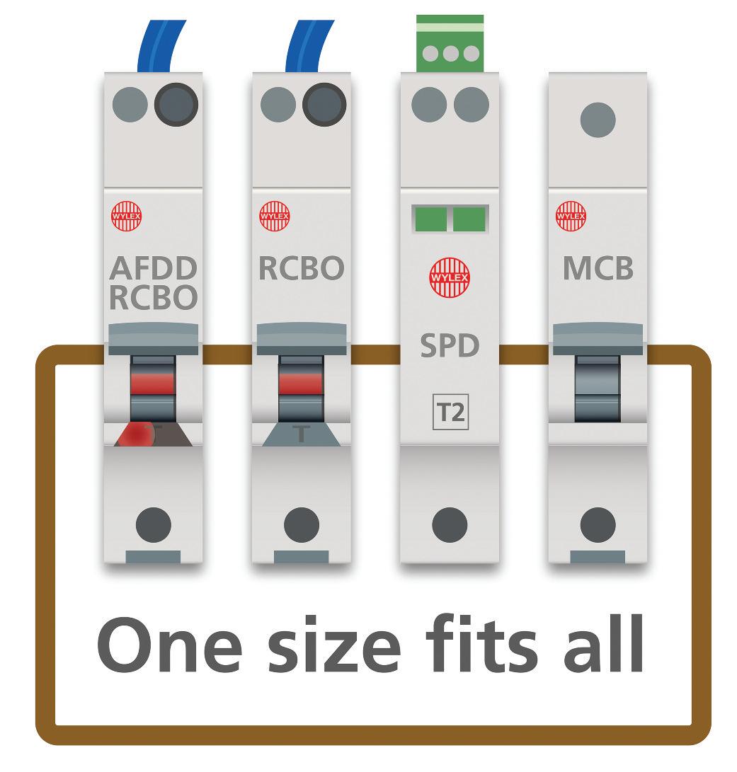
Verification
New work, such as the replacement of a consumer unit and associated devices, should be verified in accordance with the requirements of Chapter 64 of the Wiring Regulations and the relevant electrical installation certificate should be given to the person ordering the work (see Regulations 641 1, 644 1 and 644 3)
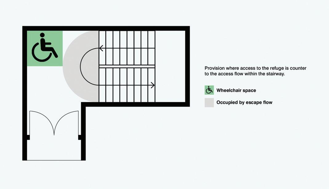


Matt
It is essential that persons can escape from a building should fire occur The building regulations in all parts of the United Kingdom have similar requirements For example, in England Regulation B1 states:
“The building shall be designed and constructed so that there are appropriate provisions for the early warning of fire, and appropriate means of escape in case of fire from the building to a place of safety outside the building capable of being safely and effectively used at all material times ”
It is always necessary for all persons to escape; this will include those with disabilities which precludes rapid and safe evacuation There will, therefore, be times when it will be necessary for persons escaping to have access to areas where it is safe to wait for a short period; such areas are called refuges.
Approved Document B Volume 2 Fire Safety 2019 (incorporating 2020 and 2022 amendments) (ADB2) gives guidance on the recommendations for refuges to ensure compliance with legislation. Further guidance is also given in BS 9999: 2017 Fire safety in the design, management and use of
buildings – Code of practice.
This article briefly considers the specific recommendation for refuges to be provided with an emergency voice communication (EVC) system conforming to BS 5839-9 and the provision of such an EVC system, such as those produced by ESP under the Beacon Range.
Refuge
The presence and nature of a refuge will need to be considered on a case-by-case basis Fig 1 is based on Diagram 3 1 and Fig 2 on Diagram 3 2 of ADB2 These detail examples of refuges formed in a protected stairway
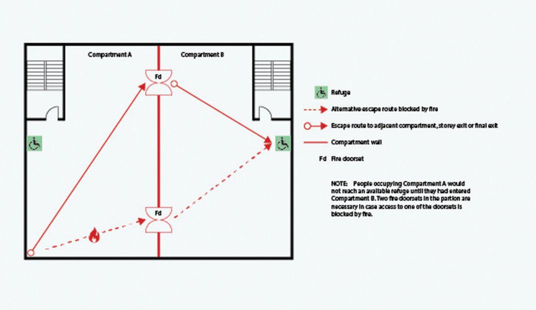
There may be instances where a refuge extends into rooms which are near those exemplar areas detailed in DB2. Annex G of BS 9999 details other examples of refuge areas
Approved Document B
In the refuge, ADB2 recommends that the EVC system consists of Type B outstations communicating with a master station in the building control room (should one exist) or next to the fire detection and alarm panel It is permitted for the EVC system to be wireless
BS 9999
Clause 45.8 of BS 9999 recognises that refuges are places of relative safety and references the normative annex G in the Standard
Once the number and locations of refuges have been decided by the key stakeholders (see Clause 5 BS 5839-9), Annex G recommends that procedures are established for independent communication between the occupants and evacuation management personnel
The recommendations detailed in clause 45 8 and Annex G of BS 9999 will require an emergency voice communication system to be installed. The emergency voice communication system should conform to the recommendations of BS 5839-9: 2021 Fire detection and fire alarm systems for buildings Part 9: Code of practice for the design, installation, commissioning and maintenance of emergency voice communication systems
BS 5839-9
The purpose of BS 5839-9 is not to provide a justification for the installation of EVC systems, rather to provide recommendations for the planning, design, installation, commissioning and maintenance of such systems
The scope to the Standard makes it clear that, other than in exceptional circumstances, EVC systems are not intended as a means of raising a fire alarm instead of manual call points (MCPs).
The Beacon Emergency Voice Communications (EVC) system is designed to fully comply with BS 5839-9:2021 for use as a Fire Telephone system, Disabled Refuge Call system or as a combined system when both Fire Telephones and Disabled Refuge Points are required
The system comprises of a Master Station and one or more outstations Additionally, the “Assist Call” emergency assistance alarm system can either be connected to the same line as a Type B outstation or connected to a dedicated line Neither the outstations nor the “Assist Call” emergency alarm system requires a separate power supply unit as each line is powered from the Master Station This has the additional benefit of each line being fully monitored and battery backed up
Each Beacon Master Station can also perform as a Beacon Repeater Station A Beacon Repeater Station mimics the Beacon Master Station both in operation and indication
The Beacon Master Station has been designed for radial star topology In most cases this will reduce the cable requirements for all ring-based systems The topology consists of spurs formed of one two-core 1 5mm2 CSA cables (soft skin enhanced up to 500 m per leg, MICC 200 m per leg) to each outstation.
If the Beacon Master Station and the Beacon Repeater Station are distributed around a site, it is essential that both Beacon Stations are on the same mains phase Powering from different phases can mean a 400 V potential can be present in a Beacon Station during a major fault incident
The designer of the EVC system should adequately consult with key stakeholders at the design stage Such key stakeholders are:
● User or purchaser,
● Supplier of the system,
● Installer of the system,
● Consultants, including architects M&E, fire safety, access, acoustic and risk assessment – clause 5
To the extent necessary, the installer of the system should consult with the designer, supplier and consultants
An EVC system is typically required in the following situations:
● In any building or sports or similar venue where there are disabled people, or people who may have difficulty negotiating the evacuation route
● In buildings with phased evacuation and/or firefighting lifts where it facilitates secure communications for building managers, fire wardens, and attending fire officers.
● At sports venues and similar complexes, where it will assist stewards in controlling the evacuation of the area in an emergency
Conclusion
The provision of an EVC system is essential in those premises where it is likely that the less able-bodied are present and where the nature of the people on the premises is likely to create problems for evacuation The EVC system will enable those responsible for managing evacuation to safely manage, insofar as they are able, the evacuation.
BROWSE THE ONLINE ESP BEACON RANGE BROCHURE AT: WWW.RDR.LINK/EAQ018
SECTION 4
ENDS! SCAN THE QR CODE TO CLAIM YOUR CPD CREDIT FOR THIS SECTION OR VISIT: WWW.RDR.LINK/EAQ019

The visual sensation of Unified Glare occurs when there is excessive and uncontrolled brightness
There are two commonly considered types of glare: the type that can be disabling and the kind that can simply be uncomfortable Whilst glare is subjective and sensitivity to it can vary greatly, the ageing and shaping characteristics of the human eye also play a part Often, the more senior the user the more susceptible to glare they become.
Overly bright light sources can induce annoyance or even pain, but they do not actually impair vision

Disability glare
Intense light sources in the field of view causing the reduction in visibility It causes a loss of visibility from stray light being scattered within the eye
Lighting arrangements and cut-off angles are two of the most important factors for minimising direct glare from luminaires However, the UGR value as a measurement of direct glare does not depend on the individual luminaire, but rather on the room and the viewer's position within each workspace
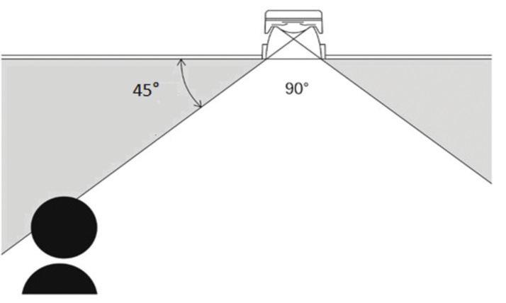
Unified Glare Ratings, simplified as UGR, are calculated using a precise formula Essentially, this formula measures the luminance of a luminaire divided by the background of visible luminance from the room
In order to truly calculate UGR, at the design stage, RAL numbers of wall and floor coverings would enable the truest form of calculation. In many cases this information is yet to be defined so
designers refer to a default set of reflectances
The UGR ranges from 5 to 40 The lower the number, the lower the generated glare For example, a UGR of 10 would mean the glare is so discreet it will go unnoticed and create a comfortable working environment, while a UGR of 30 will cause distraction and potentially discomfort to the user
UGR is applicable to lighting installations, not luminaires. The formula requires the prior knowledge of the position and brightness of each potential glare source, so is often calculated once a lighting design has been finalised
UGR calculations are accurate, but relatively difficult to work with, so they’re
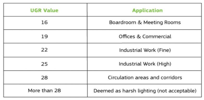
often calculated with the use of computer software Calculating glare involves summing all the light coming from all sources at a particular angle entering the eye at a particular location within each room UGR recommendations are pre-determined and set by SLL in the UK and Ireland A brief and shortform example of this can be seen in the table (pictured at the bottom of page 86)
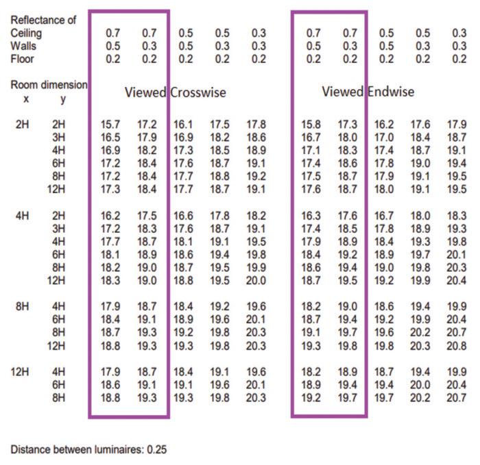
The calculation of UGR is independent of the height of the luminaires above the observer's eye (H) with luminaire spacing (also = H), as H changes the size of the room and spacing of the luminaires A typical UGR table is shown in the image (pictured, left).
You should follow these steps to determine the UGR value:
● Determine room size This can be expressed in terms of the number of luminaires in each direction.
● Determine reflectances of the room surfaces
● Generally, we would assume most spaces would conform to the first two columns of each row
● Determine viewing direction: crosswise or endwise relative to the luminaire dimensions
● Read the UGR value from the table Strictly speaking, there is no such thing as
a ‘UGR19-compliant’ luminaire in itself Luminaires do, however, support the performance of a UGR-compliant design or installation
Full compliance can only be determined once the ergonomics and geometry relative to the occupants of a space have been assessed The UGR calculation of a room where multiple luminaire types are utilised will be calculated based upon the product with the greatest Unified Glare intensity
If a manufacturer claims a product carries a UGR19 compliance, it can only be for a set of pre-determined conditions A luminaire UGR is a way to simply determine if it is likely to cause any discomfort in specific types of work or office environment
BROWSE THE 2023 ROBUS LIGHTING CATALOGUE AT: WWW.RDR.LINK/EAR012


Frank Bertie, Chief Technical Officer at NAPIT, takes a closer look at the requirements for carrying out risk assessments.


Where an electrical installer is involved in carrying out any new work, there has to be a consideration of what the work entails, where it is to be installed, who is to carry out the work and when the work will commence
With the above in mind, part of health and safety legislation requires a risk assessment of the work process to ensure the engagement of any such work does not present a danger to those carrying out the work, to persons near to the work location or any members of the public that
may have access during the work
In this article we discuss the process and provide a reminder of the risk assessment requirements prior to carrying out any new electrical work
What does the legislation require?
The Health and Safety at Work Act 1974 (HSWA 1974) and the Management of Health and Safety at Work Regulations (SI 2006 No 438) are both clear in their requirements for carrying out risk assessments and that such information should be recorded and reviewed
The HSWA 1974 is fundamentally the most important Act that every electrical installer must adhere to at all times. Section 2 (1) of the Regulations states: ‘it shall be the duty of every employer to ensure, so far as reasonably practicable, the health, safety and welfare at work of all of his employees’ Within HSWA, the term ‘his’ is generally interpreted to include all genders.
Although the Act refers to an ‘employer’, by inference it is also applied to those who are ‘self-employed’, considering the self-employed are also responsible for their own safety and those around them, whilst engaged in any working activity. In addition to the steps previously
mentioned, health and safety of members of the public and other workers within the vicinity must be taken into account during the planning of any electrical work
The Management of Health and Safety at Work Regulations (SI 2006 No 438) (MHSWR 2006) goes a step further than the HSWA 1974, in that it calls directly for risk assessments to be carried out in a multitude of instances.
MHSWR (2006): Section 3(1):
(a) The risks to the health and safety of his employees to which they are exposed whilst they are at work; and
(b) The risks to the health and safety of persons not in his employment arising out of or in connection with the conduct by him of his undertaking
As can be seen, this reiterates the message of the HSWA 1974 The employer is responsible for his employees as well as anyone who may be affected by their actions Clearly this is very important, and the MHSWR (2006) gives the same message to self-employed individuals:
MHSWR (2006): Section 3(2): Every self-employed person shall make a suitable and sufficient assessment of:
(a) The risks to his own health and safety to which he is exposed whilst he is at work; and,
(b) The risks to the health and safety of persons not in his employment arising out of or in connection with the conduct by him of his undertaking.
All risk assessments must be reviewed and revalidated if a change of circumstance becomes apparent as in the following:
MHSWR (2006) Section 3 (3)
Any assessment such as is referred to in paragraph (1) or (2) shall be reviewed by the employer or self-employed person who made it if:
(a) There is reason to suspect that it is no longer valid; or,
(b) There has been a significant change in the matters to which it relates; and whereas a result of any such review changes to an assessment are required, the employer or self-employed person concerned shall make them.
What needs to be considered for new electrical installations?
The Electricity at Work Regulations as well as BS 7671:2018+A2:2022 cover the requirements for electrical installations
Although these regulations refer to risk assessments, these are not considered to be part of the main risk assessment for work activities but do need to be taken into account
So, we need to look at what type of work is to be carried out as each installation presents particular risks and hazards and steps are required to manage any of the potential risks
Does the installation include large switchgear and equipment?
This would include machinery to safely move the equipment into place from the delivery to the final position within the premises The days of manhandling this type of equipment should be long gone due to the dangers of back and muscle injury to persons carrying out this work
The Health and Safety Executive (HSE) provides a guide on manual handling at work which refers back to MHSWR (2006) and there is further legislation covering the topic Manual Handling Operations Regulations 1992
Does any of the installation material or methods contain any risks?
All installation work carries a risk For example, during containment installation, which involves cutting, site manufacture, assembly and fixing, all of these activities must be considered as part of the risk assessment, along with any steps necessary for the provision of suitable personal protective equipment, again subject to legislation recently amended by The Personal Protective Equipment at Work (Amendment) Regulations 2022
Are any of the installation materials or processes subject to substances hazardous to health?
This is an important area for which there is legislation called Control of Substances Hazardous to Health (COSHH) It covers a wide range of substances and activities, such as dusts resulting from cutting and grinding, lubricants as well as references to COSHH found in the instructions of the relevant manufacturer
Where is the installation to be carried out?
Each type of premises and
location provides a different challenge –from a dwelling to a hospital – which can lead to a more detailed risk assessment being carried out so as to include the range of very particular requirements and regulations to be considered. These could be as follows:
● Is it a new build or existing premises?
● Is the work to be internal or external?
● Is there working at heights involved?
A new build premises would seem to be a more straightforward case, but the activities will operate in a construction site environment, where the main contractor will have a raft of site-specific requirements

In contrast, with an existing building there may not be construction site issues, but there will be a need to survey or review any records of the materials and services that exist, in order to ensure that appropriate precautions are taken, such as when asbestos is present
Who is at risk during the proposed work?
Although we’re looking at who is at risk, we do have to remember that everyone has a responsibility to ensure the health and safety of those around them
With regards to a work task, we’re trying to highlight the areas of risk to those carrying out the work, not just the work task itself, but also any materials or additional items, such as working at height Additional details would require inclusion for other trades, staff and any members of the public who have access to or are in the vicinity of the work area
When is the work to be carried out?
This is a crucial consideration as the proposed time for the work task can either increase or decrease the risks associated with the task Obviously with electrical installation or inspection and testing this would require some form of isolation to allow safe working, therefore arrangements will have to be carried out to allow this during out of normal working hours
With commercial interests, any downtime for a business is seen as a critical issue, and although domestic premises may seem more straightforward, with many employees now working from home, this also requires to be factored in
When carrying out risk assessments it is vital that the records are adequate and accurate, covering all of the risks associated with the planned work activities. Remember that the Certificates, Records and Assessment documentation produced during your current risk assessment will provide the starting point for the review and maintaining safe working in the future

The method for recording the risk assessment information is only relevant if it is accessible and can be viewed as required Although paper documentation can be suitable, the use and application of software systems for this purpose provide a more effective resource
Each risk assessment should be unique to the work activity and although part of the information can be reused for future risk assessments, the particulars for each work task must be reviewed The
monitoring of the risk assessments carried out will assist in improving the health and safety of the business by learning and adapting the work processes
The
Management Code


BS 7671 permits the use of a range of supplies to equipment on construction sites. This article from the experts at NICEIC summarises the requirements in Section 704 for the use of reduced low voltage (RLV) supplies in such locations.


when considering the use of RLV, it is important to meet the requirements of both Section 411 8 of BS 7671 and also those of BS 4363: 1998 (2013)Specification for distribution assemblies for reduced low voltage electricity supplies for construction and building sites.
Where the use of extra-low voltage is impracticable for functional reasons and/or there is no requirement for the use of SELV or PELV, an RLV system may be used (411 8 1 1)
Such types of system have been used on construction sites for many years as a means of reducing the risk and severity of injury from electricity whilst providing an adequate supply
voltage for maintaining correct functionality of site equipment.
For this reason, Note 1 of Regulation 704 410 3 10 provides a strong preference for the use of RLV for the supply to portable hand lamps for general use, portable hand tools and local lighting up to 2 kW
RLV is a supply in which the nominal circuit voltage does not exceed 110 V AC
between lines. For three-phase circuits, the voltage should not exceed 63 5 V between a line and earthed neutral and, for single-phase circuits, 55 V between a line and earthed midpoint (411 8 1 2) This reduced voltage level provides the primary means of protection against electric shock in the RLV system. As such, historically, a disconnection time was not specified
Permitted sources of supply
The supply to an RLV circuit should be derived from one of the following sources:
● A double-wound isolating transformer meeting the requirements of BS EN 61558-1 and BS EN 61558-2-23
● A motor-generator in which the windings provide a degree of isolation equivalent to that provided by the windings of an isolating transformer
● A source independent of other supplies, such as an engine-driven generator (411 8 4 1)
The secondary windings of a transformer or generator providing the supply to an RLV system must be connected to Earth
As shown in Fig 1, for three-phase supplies, the connection is made at the neutral (star) point and for single-phase supplies the connection is made at the midpoint (411 8 4 2)
Basic protection
Basic protection must be provided by either basic insulation suitable for the maximum nominal voltage of the RLV system or by the use of barriers or enclosures (411 8 2)
Fault protection
All exposed-conductive-parts of the RLV system must be connected to Earth For automatic disconnection of supply during a fault to earth, each line conductor should be protected by either an overcurrent protective device or an RCD. Additionally, Clause 5 5 of BS 4363 requires any circuit-breakers used on output circuits shall disconnect all circuit conductors simultaneously Regulation 411 8 3 of BS 7671 calls for a maximum disconnection time of 5 seconds for an RLV system.
The maximum value of earth fault loop impedance to achieve this disconnection time can be found by the application of one of the following formulae derived from the expression given in Regulation 411 4 4:
For fuses or circuit-breakers:
Where:
U0 is the nominal AC rms voltage to Earth, 55 V for 1-ph RLV or 63.5 V for 3-ph RLV (411.8.3)
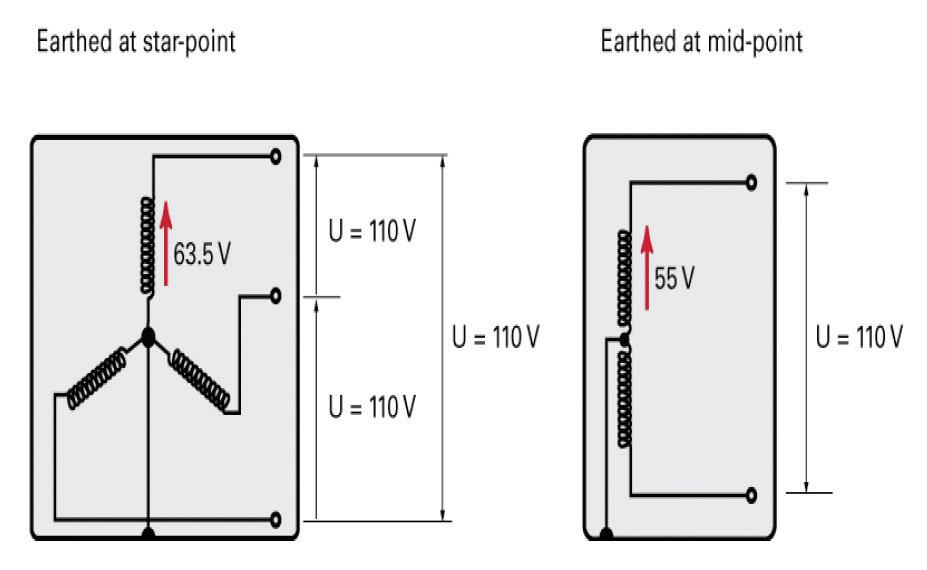
Ia is the current in amperes (A) causing the automatic operation of the disconnecting device within 5s Cmin is the minimum voltage factor, taking account of voltage variations depending on time and place, changing of transformer taps and other considerations (typically taken as 0 95)
Alternatively, Table 41 6 of BS 7671 provides maximum earth fault loop impedance values for circuit-breakers to BS EN 60898, RCBOs to BS EN 61009-1 and for general purpose fuses to BS 88-2 fuse systems E and G
It should be noted at this point that Clause 7 1 of BS 4363 recommends for a single-phase transformer assembly (TA/1) that:
● any single-phase output circuits having a rating up to 32 A supplying socket-outlets, and
● any circuits in excess of 32 A, whether supplying circuits directly or via socket-outlets,
must be protected by double-pole circuit-breakers
Similarly, in a three-phase transformer assembly (TA/3), any three-phase circuit having a rating up to 32 A supplying socket-outlets should be protected by
triple-pole circuit-breakers (Clause 7.3). This precludes the use of fuses at the origin of circuits in such site assemblies
Clause 7 also states that any socket-outlets in excess of 32 A rating must be mechanically or electrically interlocked to prevent the on-load removal of the plug.
Where fault protection is provided by an RCD, the following condition must be met:
IΔn × Zs ≤ 50 V
Where:
(I∆n) is the rated residual operating current of the RCD providing fault protection
However, where an RCD is relied upon for fault protection for example, where the earth fault loop impedance value is high, an appropriate overcurrent protective device must still be provided in each line conductor in accordance with Chapter 43 (411 4 5; 411 5 2)
Particular requirements where the installation forms part of a TT system BS 7671 permits the use of a Class I enclosure to house an RCD at the origin of an installation forming part of a TT system subject to the use of live conductors having double or reinforced insulation on the supply side of the incoming device (531 3 5 3 2 201)
Similarly, Clause 6 5 4 1 of BS 7375 1 states that a metallic enclosure may be used if insulating glands, gland plates or other measures, providing the equivalent Class II insulation between the incoming supply conductors and equipment metalwork are taken to reduce the possibility of earth faults
However, this clause also states that, wherever practicable, an insulating enclosure should be used to avoid the risk of earth faults between incoming cables and metalwork on the supply side of the principal protective device(s)
It should also be recognised that any specific requirements imposed by a Distribution Network Operator (DNO) as conditional to the provision of a supply on a construction site must also be met. For example, Clause 6.2.2.2 of Engineering
Recommendation G12, issue 4 2 does not permit any exposed-conductive-parts before, or enclosing, an RCD As a result, an RCD at the origin would have to be housed in an enclosure of Class II or equivalent all-insulated construction

Every plug, socket-outlet, luminaire supporting coupler, device for connecting a luminaire and cable coupler used in RLV systems should have a protective conductor contact that is not dimensionally compatible with those used for any other system in use on the particular construction or demolition site (411 8 5)
All plugs and socket-outlets including, cable couplers and cable connectors - of current rating 16 A up to 125 A should meet the requirements of BS EN 60309-2 3 (704 511 1) Unless otherwise specified in that standard, the requirements of BS EN 60309-1 4 are also applicable Accessories to BS EN 60309-2 are classified as non-interchangeable with respect to their current and voltage ratings
Clause 7 7 of BS EN 60309-1 states that the operating voltage of accessories may be indicated by colour. Accessories suitable for operation at 100 – 130 V, should be identified by the colour yellow While there is no requirement to do so, this colour coding system is often also applied to the outer sheath of flexible cables
The reduced low voltage (RLV) system provides both a safe system for use in the harsh environment typically associated with construction and demolition sites whilst providing a source of supply that is sufficient for the majority of site electrical equipment to function properly
When an RLV system is employed it is important that all relevant requirements relating to the installation of such systems are met This will require reference to a number of British Standards including in particular BS 7671 and BS 4363.
Key references:
1 BS 7375: 2010 Distribution of electricity on construction and demolition sites – Code of practice
2 Engineering Recommendation G12 Issue 4 - Requirements for the Application of Protective Multiple Earthing to Low Voltage Networks
3 BS EN 60309-2:2022 Plugs, fixed or portable socket-outlets and appliance inlets for industrial purposes Dimensional interchangeability requirements for pin and contact-tube accessories
4 BS EN 60309-1:2022 Plugs, socket-outlets and couplers for industrial purposes General requirements
Are your clients paying for electricity they don’t use? Chauvin-Arnoux UK’s Julian Grant discusses power factor, what it is and why you should be constantly monitoring and correcting it.
While business owners and accountants are worrying about energy prices, many are completely unaware that for the sake of some simple monitoring and correction equipment, their business may be seriously falling short of what is required to be electrically efficient

Recent cases discovered by a renowned Power Quality Improvement Service have identified many examples where as much as half of the electricity being consumed by businesses is literally going to waste
And high energy bills are only part of the problem Power factor also impacts on the reliability of the network itself and can cause a variety of electrical issues that may result in the early failure of capital equipment. This equipment often gets replaced at great expense without the root cause ever being observed or identified Poor power factor can also impact heavily on the capacity to add new loads when a business expands
Saving money by using a cheaper supplier and employing an energy
comparison consultant to get the best deal is an obvious thing to do, and easy to justify However, poor power factor is now such an issue, the businesses installing power factor correction, and saving their customers thousands of pounds on their electricity bills by doing so, are literally inundated with work.
What is power factor?
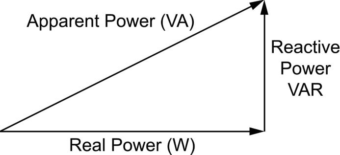
Some electrical equipment used in industrial and commercial buildings requires an amount of reactive power in addition to real or active power in order to work effectively. These tend to be items with copper windings in them, especially transformers, motors, induction heaters, arc welders and compressors
Reactive power (kVAr) is the vector difference between real or active power (kW) and the total power consumed, which is called apparent power and measured in kVA Power factor is a ratio of the real power that is used to do work and the apparent power that is supplied to the circuit It’s quite easy to understand if you consider a pint of beer, where the whole glass that you pay for is the apparent power, the bit you want
most (the beer) is the active power, and the bit you want as little of as possible (the head) is the reactive power.
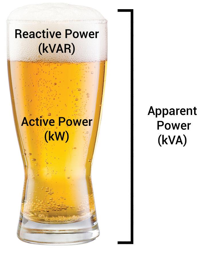
A full pint with no head would represent a power factor of 1, or unity power factor, and in that situation, there would be no reactive power. In reality a power factor greater than 0 95 is generally aimed for –0 98 if you can get it That’s the equivalent of a pint with a nice small head on it!
According to The Carbon Trust it is not uncommon for industrial installations to be operating at power factors between 0 7 and 0.8, which is surprising since measuring power factor is not at all difficult
It can be routinely measured using portable test instruments, or alternatively, can be permanently monitored in real-time with constantly displayed values, while also showing a multitude of other useful parameters including voltage, current and energy consumption In this situation it is also possible to set alarms to remotely warn the facility manager if the power factor strays below a pre-set limit
Similarly, while specification of a power
factor correction (PFC) system requires knowledge of several factors including the voltage level and typical usage of the reactive loads on-site, the usage profile across the site, and the power quality required by the on-site loads, all of this is easily measured and calculated PFC systems are a fraction of the cost of the potential savings they can bring
The simplest form of PFC involves fitting capacitors, and it is worth taking expert advice on the system that will suit you If a single machine has a poor power factor, capacitors can be connected in parallel with the device, so that they compensate for the poor power factor whenever the machine is switched on
If the power factor of a site is permanently poor and no single item of equipment is solely responsible, fixed PFC can be connected across the main power supply to the premises
Where many machines are switching on and off at various times, the power factor may be subject to frequent change
In this case the amount of PFC needs to be controlled automatically. In other words, the banks of capacitors need to be selectively switched in and out of the power circuit appropriately There are various solutions on the market for performing this capacitor bank switching automatically.
Following a request in June 2016 to monitor its electrical supply by a metal fabrication business specialising in the design and manufacture of tubular and sheet metal sub-assemblies and screens, an average power factor of 0 73 was measured over a period of four days.
To put that into perspective, a power factor of 0 7 requires approximately 43% more current to do the same thing as an installation with unity power factor. A power factor of 0.5 requires approximately 200% (twice as much) current to handle the same load
After the installation of appropriate automatic power factor correction equipment in January 2017 the average power factor monitored over a complete week increased to 0 98 The apparent power was reduced by just over 13%
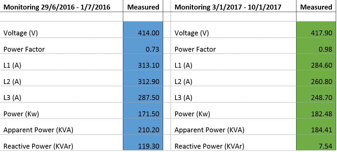
Current dropped by between 10% and 17% per phase, and reactive power was reduced from 119kVAr to less than 8kVAr These reductions were made even with a slight increase in demand during the six months between the initial measurements and the corrective action.
Based on a real to apparent power difference prior to the power factor correction of 38 7 and a real to apparent power difference after the power factor correction of 2, and assuming an electricity cost of £0 15 per kWh, this would equate to a saving of over £8,800 per year in reduced electricity charges
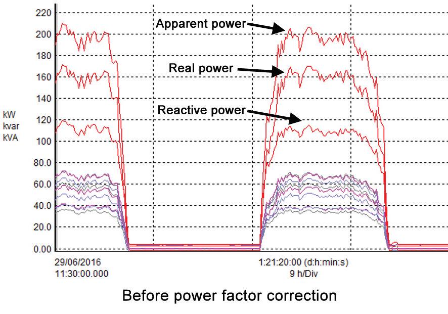
In light of the ever-growing price of the electricity clients are buying, it is probably about time they checked their power factor to see how much of that electricity is being paid for but not used
BROWSE CHAUVIN ARNOUX’S LATEST TEST &
BROCHURE AT: WWW.RDR.LINK/EAR014

Q I’ve been asked to commission a fire alarm system that a subcontractor has installed for our client. The spacing of the detection is all within BS 5839-1:2017. However, the detection on suspended ceilings is just a hole with two lumps of wood screwing the base up without any back box, and no glands or grommets protecting the cable (see picture). I spoke to the contractor, and he said he doesn’t have to do it because it does not say in BS 5839-1 that penetration through a suspended ceiling must have a back to it Can you clarify please?
This type of installer (or worse still, the company in question) boils my blood
Essentially, they’ve taken a theory-only BS 5839-1 installation course, and away they went with a CPD certificate saying they’re now an advanced installer
The short answer to the question is that it must have a back box or, as it is worded in BS 7671, be in an enclosure.
The longer answer is as follows: BS 5839-1 is one of many standards that should be used during the installation of the fire alarm system Within that standard, BS 7671 is referenced no less than 16 times, including, notably, clause 37 Installation that states the entire system should conform to the requirements of BS 7671
This practice breaches several clauses in BS 7671:2018 and amendment 2: 2022 – my first thought was that it breaches clause 526.5. Every termination and joint in a live
conductor or a PEN conductor shall be made within one of the following:
- A suitable accessory that complies with the appropriate product standard.
- An equipment enclosure that complies with the appropriate standards
- An enclosure partially formed or completed with building materials that are non-combustible and meet the requirements of BS 476.4.
So, what does that mean? Basically you should either use a suitable back box/enclosure purchased from your electrical supplier that meets the standards or you can make an enclosure out of fire-resisting materials.
In short, buy a galvanised metal conduit box or a plastic fire-resistant one
With cables where the sheathing is removed, it also breaches Clause 526 8, which states that where cables have been stripped to the bare cores at the termination, they shall be enclosed.
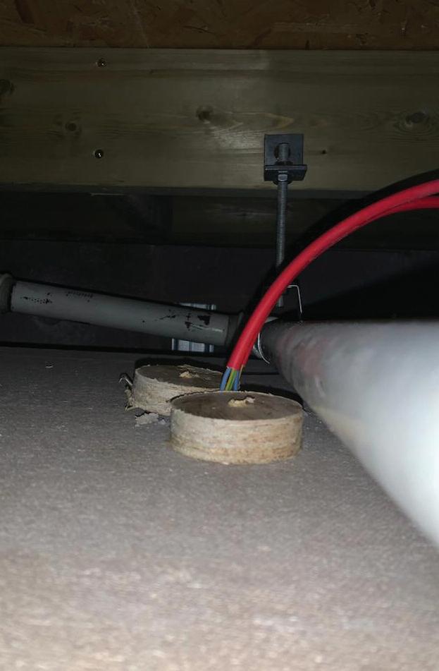
I recently spoke with Senior Technical Manager at the ECA, Gary Parker, who is named in BS 7671 and he listed three other clauses it breaches

521 10 1 Installation of cables 522.8.1 Other mechanical stresses 522 8 5 (dependent on the installation)
This is why when we train to BS 5839-1 at ZZEUS, we always state during our installation training that the reason there are only three clauses in BS 5839-1 on installation is that the bulk of the installation should comply with BS 7671
By not doing so the installer is in serious breach of BS 5839-1:2017 clause 3 12: A competent person who is a person with the relevant current training and experience, and with access to the requisite tools, equipment and information, and capable of carrying out a defined task
DO YOU HAVE A QUESTION YOU'D LIKE ANSWERED?
EMAIL YOUR QUERIES TO:
TOM@ZZEUS.ORG.UK

There’s no excuse for either poor work manship or a lack of competence, and this submission proves that.
The opening in the enclosure for this SWA cable appears to have been made too large for the gland that fits the cable; that said, the nex t size up probably would have done the job, so it was either unavailable, or the installer may have chosen not to bother, for some reason.
The gland per forms many jobs, not just to anchor the cable securely but also to provide a connec tion to cpc or the main ear th terminal (ME T ) or to terminate into an enclosure in a similar manner to a conduit or MICC cable I t also stops undue strain on the terminations from the weight of the cable.
There may be a lack of competence or understanding on the par t of the installer, but to be fair, there is a correc tly fitted and glanded cable to the right that would suffice as an instruc tion of how to fit one, or at least what it should look like!
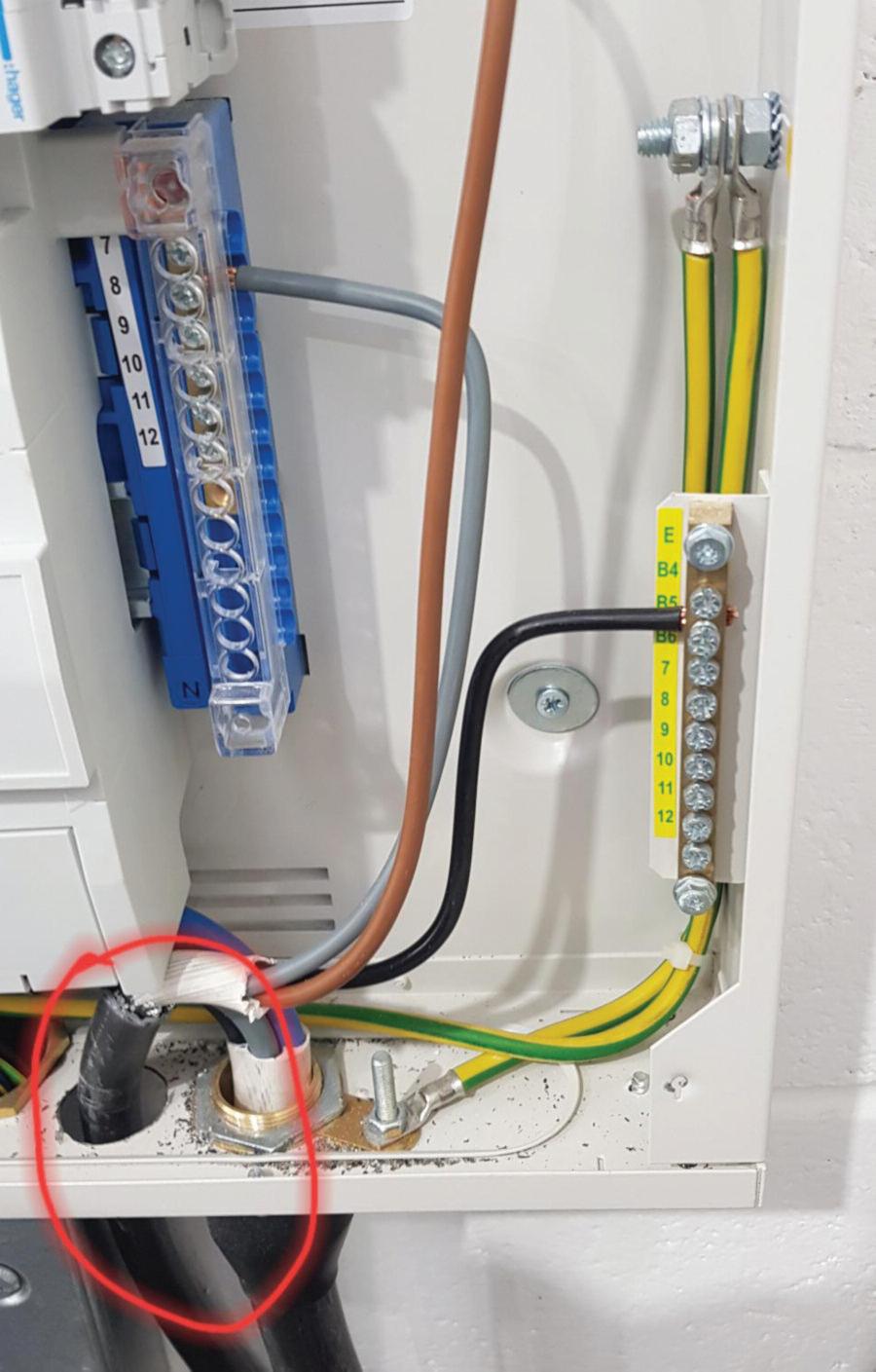
There is also a significant amount of swar f from the hole saw that produced the opening, which should have been removed, as this k ind of swar f contamination can cause faults and issues later if they come into contac t with any terminations
On top of this, it is pretty clear that the armour of the cable has not been connec ted to the cpc; whether this was done on purpose to isolate the armouring for some reason is not k nown, so rather than code against it for non- connec tion to the cpc, I feel an FI would be a better call here
Overall this is a pretty poor show of technique, competence and work ethic.
Regulation infringements and Codes applicable to this observation would be:
SWA cable not glanded in accordance with manufacturers guidance strain on terminations
SWA cable likely armour not connected to circuit cpc or main earth terminal
134.1.1, 134.1.4, 522.8.5
134.1.1, 543.2.7,54
2.1.3.3
134.1.1
Poor workmanship, with swarf left in the consumer unit, could be problematic in the future.
Need help with cracking those all-impor tant EICR codes? Ever y month the technical team at NAPIT will be studying your latest ‘Caught on Camera’ photos and offering advice on the next steps, should you find a similar installation. If you want the team at NAPIT to help crack your codes then send your pic tures through to us at: pe@hamer ville.co.uk
HAMMOND ELECTRICS: THIS WAS FOUND RECENTLY ON A SUMMER HOUSE THE MAIN EARTH WAS IN A BREAKER AS IT DIDN’ T FIT IN THE TERMINALS PROVIDED, BUT WAS SWITCHED OFF AND WASN’ T CONNEC TED TO THE BOARD ITSELF, SO THERE WAS NO EARTH AT ALL!
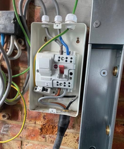
There are a couple of issues here, so I’ll star t at the top and work down Firstly, we have the supply conduc tors and cpc entering a ferrous enclosure through separate openings, which may lead to heat build-up issues in the surrounding enclosure by eddy currents Although this is a ‘shall not do’ from a BS 7671 perspec tive, we must understand that BS 7671 isn’t a purely domestic document; it covers many aspec ts in its scope.
Generally speak ing, eddy currents don’t tend to become problematic until the load current is in excess of 100-125 A continuously I n a domestic scenario, it ’s unlikely we’ll see too much of an issue on lightly loaded circuits or shor t- duration high loads That said, it has to be coded, so without signs of thermal damage and with a low-load design signature, it ’s unlikely to be an issue I f thermal damage were present, we’d need to up the coding severit y
Secondly, and possibly the most dangerous, is the switched overcurrent protec tive device (OCPD) placed in the cpc via an MCB. This is incredibly dangerous from both the switching element and the fusing element Fusing in cpcs is not allowed, and switching is only allowed for specific reasons under stringent design fac tors using devices that simultaneously disconnec t all live conduc tors and
the cpc, such as may be required for alternative supplies
Both of these have significant potential for danger and harm
We’ll overlook the failure to correc tly mount the MCB on a din rail, as the device isn’t supposed to be there!
Thirdly, the load and supply sides of the switch have been connec ted the wrong way around. Although this won’t cause an issue in day-to - day operations, the load-side terminals will be live when the switch is isolated Likewise, the fuse carrier terminals may give access to par ts that would normally be de - energised when the switch is in the off position, and the fuse carrier is swung out to replace the fuse. This k ind of poor installation prac tice has the potential to cause harm if an item is expec ted to be de - energised and then turns out to be live There are also a couple of issues with the adequate mark ing of the SWA conduc tors, which also need to be addressed.
The Observations, Regulation infringements and Codes applicable to this observation would be:
Supply conductors and cpc entering a ferrous enclosure through di erent openings, no eddy current reduction methods in place, no signs of thermal damage
Supply and load side conductors reversed, giving access to live parts when they are expected to be de-energised
Overcurrent protective device (OCPD placed in a circuit protective conductor (cpc)
SWA conductors not adequately marked to indicate neutral and cpc conductors
MCB in an open circuit switched con guration placed in a cpc
134.1.1, 521.5.1
132.10, 132.15.201, 134.1.1, 422.3.13
132.14.1, 134.1.1
134.1.1, 514.3.1
132.14.2, 134.1.1, 543.3.3.101
The A2:2022 18th Edition Codebreakers publication is priced at £22.00 (members) and £24.00 (non-members). It is available in both hard copy and digital versions
* Price is VAT exempt and excludes postage and packaging.
C3
Often overlooked, the electric cable is a fundamental ingredient in any Infrastructure project globally
The greater need for more power, more data transmission and more of everything, in general, has driven significant development of cable technology over the years
In the 1880s, the first cables were insulated with gutta percha, a natural latex material produced from the sap of trees of the same name. In the late 19th century, paper cables were becoming more popular and could operate at voltages up to 10KV However, in the 1930s in Germany, the evolution of the numerous polymeric insulation materials in use today started to gather pace, and by the 1950s, PVC cables were more commonplace Other materials, such as chlorosulphonated polyethylene (CSP), were developed
From this point onwards, the development and progression of cable technology to fulfil the ever-growing requirements of power and a data-hungry
world have continued In the 1970s, using XLPE as an insulating material significantly developed in the power transmission and distribution sector, replacing paper-insulated cables with a much improved dielectric property At this time the use of PVC and XLPE was widespread, however due to the growing uses of cables in a wide range of applications with high power requirements, the suitability of some of these materials was brought under scrutiny
There have been several high-profile tragedies that have driven change, such as HMS Sheffield going down in flames during the Falkland war (1982), the Kings Cross station disaster in 1987 which resulted in the loss of 31 lives, as well as the Dusseldorf airport fire in 1996
In all these instances, the presence of choking black smoke and acidic gases were deemed to be a significant contributor to the loss of life due to the inability to evacuate and the respiratory issues caused by the smoke and fumes, with burning PVC cabling cited as one of the contributory factors in the smoke and fume production.

It has been established that when combusted PVC evolves, significant amounts of choking black smoke and acidic fumes are in the form of hydrochloric acid This is often the case when it comes to in internal cabling, specifically in areas of high human traffic As a result, an alternative to PVC was required.
The detrimental effects of PVC and other halogenated materials in the form of the evolution of acidic, choking, dense smoke-producing fumes and gas in the event of fire have led to the development of materials which offer a much cleaner burn This is particularly important in areas where public evacuation in the event of a fire is of the utmost importance, and hence there has become greater regulation and de-facto regulation in airports, high-rise buildings, and hospitals, to name a few This material evolution has been a journey, though, with several advances
The primary reason for this is that halogenated flame-retardant materials chemically disrupt the production of free
Where did halogen-free flame retardant cables come from and why are they important? Mark Froggatt, Technical Director at BASEC, explains more.radicals and effectively shut down the combustion process Halogen-free materials rely on inorganic materials, such as aluminium trihydrate ATH or magnesium dihydrate MDH, which works by withdrawing heat from the plastic during its decomposition into metal oxide and water. The water vapour propagates and reduces the fuel supply to the flame
This creates formulation problems in that the polymer is required to accept a large amount of mineral filler and maintain some mechanical and electrical properties – mutually exclusive, as adding the filler inherently reduces both.
When it comes to the maintenance of electrical properties, the inorganic materials significantly reduce the dielectric properties of materials such as polyethylene, considered the best polymeric insulator available. This makes using halogen-free low smoke compounds as insulators more difficult, as the primary function of the insulator is compromised
Over the years, there have been many advances in the properties of halogen-free materials in cables The dichotomy between electrical/mechanical performance and flame retardancy has been addressed in a number of ways, with chemical additives allowing increased use of mineral fillers, polymer composition and
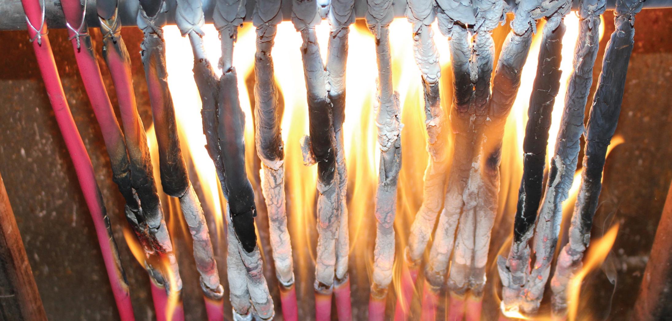
the development of "thermoplastic elastomers" such as Ethylene Vinyl Acetate Copolymer (EVA)
These materials allow significantly higher amounts of mineral filler to be incorporated into the compound to give a higher flame-retardant performance. This does, however, reduce the dielectric properties. Due to this, the usual mechanism for reduced flammability in halogen-free cables adopts the approach that the cable is protected from fire from the outside High-performance, low-flammability cable sheaths are employed to prevent the interior of the cable from becoming compromised by the fire In this way, better dielectric materials such as polyethylene and cross-linked polyethylene can be used as insulation – allowing for better data transmission in data cables (where data speed and integrity are becoming more prominent in a data-driven world) Likewise, smaller wall cables for medium voltage cables are used in buildings –which is becoming increasingly popular
So, why is third-party approval important? High-performance flame-retardant materials allow an improved reaction to fire performance, although it is critical to the cable performance that these are used in suitable applications
The fact that the technology employed in these materials comes at a higher cost
means that the manufacturer must use more expensive materials in their cable designs In today's ultra-competitive world, this leads to the typical discussion around ‘golden samples’, where high-end materials are used for type approval tests, and a cheaper, less effective material is used for ongoing production.
This potential risk can be mitigated with a BASEC product approval, where all cable designs are tested annually, and materials are fingerprinted to ensure that the approved materials are used on an ongoing basis. This type of product approval, along with the CPR/UKCA approach to product selection, means that building designers and specifiers can have peace of mind when it comes to cable selection of BASEC approved products
LEARN MORE ABOUT BASEC CABLE TESTING AND CERTIFICATION AT:
WWW.RDR.LINK/EAR015
SECTION 5 ENDS!
SCAN THE QR CODE TO CLAIM YOUR CPD CREDIT FOR THIS SECTION OR VISIT:
WWW.RDR.LINK/EAR016

Acable embedded in a wall or partition at a depth of less than 50 mm from the surface can be vulnerable to penetration by nails, screws and the like, leading to a risk of electric shock or fire It is therefore important that cable routes are properly planned and adequate measures are taken to ensure that cables are installed to meet the requirements for protection against impact and, in particular, those of Regulation Group 522 6 of BS 7671
Where a wall or partition contains significant metallic parts, such as a metal-framed structure (see Fig 1), there is a greater risk that, as a result of damage to a cable, all the metallic structure of the wall or partition may become live For this reason, BS 7671 treats walls or partitions
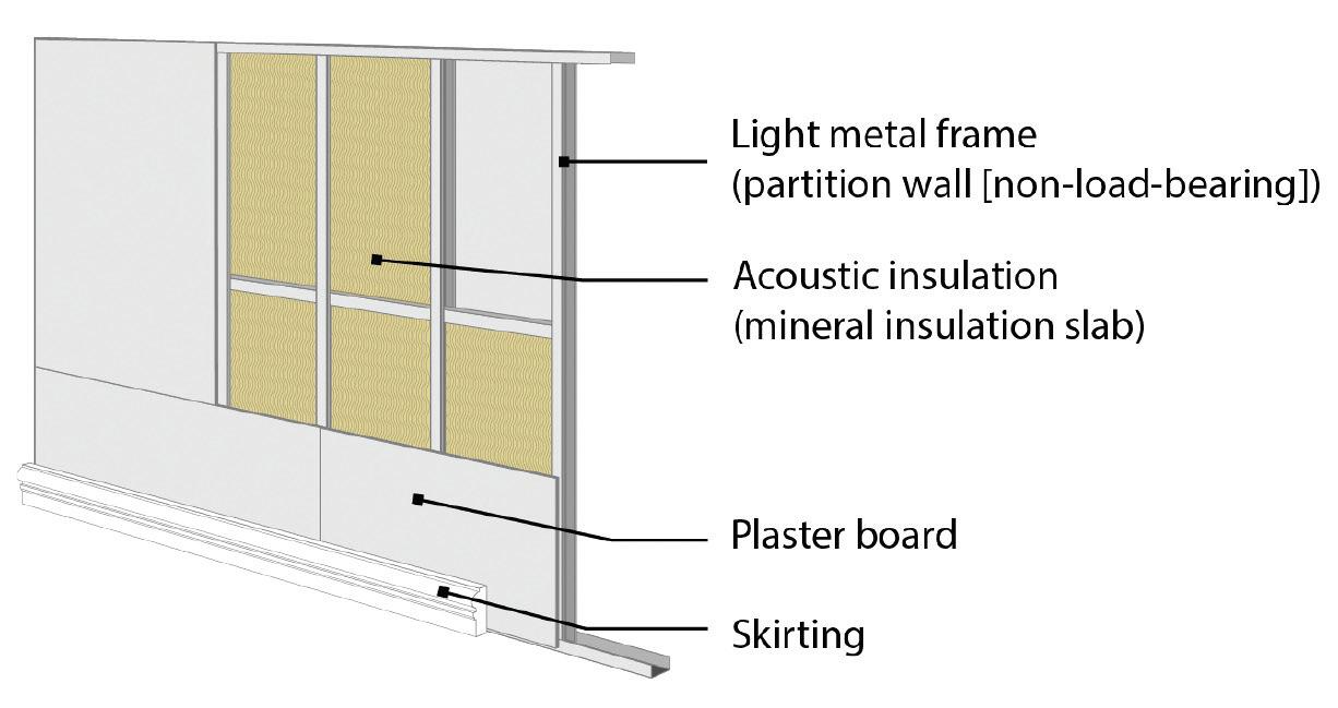
containing significant metal parts differently to those with a traditional construction using timber studding
General requirements for positioning and protection of cables
Regulation 522 6 202 of BS 7671 deals with the requirements for cables installed in a wall or partition of traditional construction (for example brick, block or timber) at a depth of less than 50 mm from the surface of the wall or partition Where the position of an accessory, point or item of switchgear can be determined from the reverse side of a wall or partition less than 100 mm thick, then the zone also extends to the reverse side Cables intended to operate at low voltage not incorporating mechanical protection, or not provided with such a means of mechanical protection sufficient
to satisfy the requirements of regulation 522.6.204, must be protected by an RCD with the characteristics specified in regulation 415 1 1
Prescribed zones in accordance with 522.6.202
When planning cable routes and installing cables within a prescribed zone, consideration must be given to both sides of the wall or partition, especially where the thickness is less than 100 mm and there is access to both sides
Consider a building, for example, where proprietary panels less than 100 mm thick are used to form a partition wall within a room and where access is available to both sides Such panels may incorporate vertical service routes (channels for cables or pipes), positioned midway between the surfaces
Cables installed in these routes will not be more than 50 mm from either surface of the partition Therefore, unless an accessory, point or item of switchgear is mounted within a prescribed zone, such as:
● within 150 mm of the top of the wall or partition; or

● within 150 mm of an angle formed by two adjoining walls or partitions;
then a cable not meeting the requirements of regulation 522 6 204 must be routed to the point, accessory or item of switchgear, only in a zone running horizontally or vertically, as shown in yellow in Fig 2.
Note: This zone will also extend to the reverse side of the wall or partition, where the position of the accessory, point or item of switchgear can be determined from the reverse side
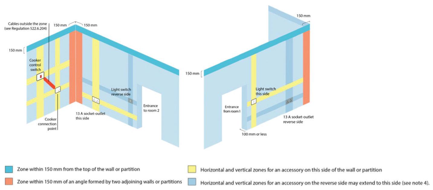
Satisfying Regulation 522.6.202 by other methods
Where a cable is installed outside a prescribed zone, as shown in Fig 2, the requirements of regulation 522 6 202 may also be met by complying with one or more of the methods given in regulation 522 6 204, including:
Cables incorporating an earthed armour or metal sheath
Where a cable such as mineral insulated copper sheathed or steel wire armoured is employed, the earthed metallic sheath or armouring of the cables is required to meet the requirements for a protective conductor for the circuit concerned relating to electrical continuity and cross-sectional area
Cables enclosed in earthed conduit, trunking or ducting
In principle, an earthed steel conduit, trunking or ducting utilises the same method of protection as a cable with an earthed metallic covering and, by construction, provides a higher degree of protection against mechanical damage.
Cables may be provided with mechanical protection sufficient to prevent the penetration of the cable by nails, screws and the like. The mechanical protection,
normally metal and approximately 3 mm thick, need not be earthed
However, in some circumstances, such mechanical protection may not be sufficient to ensure that a cable cannot be penetrated, for example where the fixing methods of other trades employ nail guns
Mechanical protection would therefore be unacceptable, as metallic capping and often proprietary protective plates would not provide sufficient protection against such an impact
Cables forming part of a SELV or PELV circuit
A cable forming part of a SELV or PELV extra-low-voltage circuit meeting the requirements of regulation 414 4 may be used as an alternative to minimising the risk of electric shock in the event of impact to the cable
However, the cable must still be installed in a manner that minimises damage from impact, abrasion, penetration, tension or compression during the installation or maintenance process, whilst also satisfying the requirements of regulation 522 6 202
Additional protection by means of an RCD Additional protection by means of an RCD with a rated residual operating current (IΔn) not exceeding 30 mA (415.1.1) must be provided in all cases where a cable not complying with regulation 522 6 204 is installed in a wall or partition at a depth of less than 50 mm from the surface
It should be remembered that, as well as being provided with additional protection by an RCD, a cable not
complying with regulation 522.6.204 must still be installed in the ‘prescribed zones’ as described previously and given in indent (i) of regulation 522 6 202
Additional protection to cables installed in a wall or partition including metallic parts
Regulation 522.6.203 requires a cable installed at any depth in a wall or partition with internal metallic parts, excluding fixing items, such as nails, screws and the like to be provided with either:
● additional protection by an RCD with the characteristics described previously, or
● one of the measures described in regulation 522 6 204
In addition, regulation 522 6 203 also requires a cable installed at a depth of 50 mm or less from the surface of a wall or partition with internal metallic parts, to meet the “prescribed zone” requirements of regulation 522 6 202
Other considerations to protect cables against damage
Where cables fixed on walls or partitions will subsequently be concealed by “wet” building materials such as plaster or mortar, consideration should be given to the provision of a protective material such as capping to minimise the risk of damage caused by trowels and the like during the application process (522 8 1)
Summary
In order to minimise the risk of impact and the resultant danger, cables embedded in walls and/or partitions at a depth of less than 50 mm from the surface must be installed in accordance with the applicable requirements of BS 7671, and in particular, those of regulation group 522 6

This month’s spotlight is about the all-important sales sector Sales is all about building relationships, and managing your pipeline, process, and automation This is the left arm of our human body model that we use to describe our Bright Business Advice 7-Sector Orbit

The word we use to represent the five levels in the sales sector – from basic to advanced – is C.L.O.S.E.
The first letter is C, which stands for CONSISTENCY
A key reason for low sales is the absence of consistency The manner in which you and your team handle clients is a critical aspect of the sales process Having spent a decade in corporate sales and a furth 18 years coaching, I’ve developed a sales process that we use with our clients – the R A P I D sales process It is also an acronym:
R = Relationships
Establishing strong relationships cultivates trust, leading to more enjoyable business interactions with individuals It's worth investing time in building authentic connections with your prospects, as they may eventually turn into customers who also become friends. These are the kind of people that you genuinely enjoy doing business with, so invest in those relationships for long-term success
A = Ask
The way you delve into the fear, frustrations, or desires of those potential customers demonstrates your knowledge by showing you know the right questions to ask and that you’re doing the groundwork
This is all about getting the potential customer to make a decision and then move them on to the next step of the sales process I recommend using the method in the book The Perfect Close by James Muir
Now back to the second letter of C.L.O.S.E, which is L. This ands for LITERATURE
P = Present
H o w w i l l y o u p r e s e n t t h e s o l u t i o n?
W i l l y o u p u t i t i n a f o r m a t t h a t t h e y w a n t t o l o o k a t ? W i l l i t b e a w r i t t e n t e n d e r o r q u o t e, p r e s e n t a t i o n o r c o m m u n i c a t e d v e r b a l l y ?
I = Identify
Whenever you provide a solution to a customer, you should always give them three levels in your offer: Silver (economical), Gold (middle ground), and Platinum (top end). This way, they feel they have a choice and it’s not just a ‘yes’ or ‘no’ decision
you got literature to back up ales, that will position you as the and represent the quality of your business? This could be case studies, company information folders or brochures, testimonials, product specs/demos, etc
By compiling quality literature you can prove to your prospects that your product or service is the best choice The more evidence you can provide, the easier it is to take away the hesitation that potential customers may have about investing in your product or service.
If your sales are lagging, it may be worthwhile to evaluate the literature you provide to clients Does it
effectively educate them towards a purchase, or are they left with unanswered questions?
The third letter is O, which stands for OUTPUT
To increase sales output, it's essential to have an effective CRM (Customer Relationship Management) system to manage all the opportunities in your pipeline That's why we developed the Bright Marketing Machine software, which helps us and our clients manage the sales process more efficiently. With a CRM system, you can measure your sales progress, track completed surveys or tenders, and assess your conversion rate You can also monitor your prospects as they move through the stages of the sales pipeline, set reminders to follow up, and keep client notes to remember specific project details


Remember, what gets managed gets focused on and ultimately gets improved To stay on track, it's crucial to set monthly, quarterly, and yearly targets for your business and for each targeted salesperson. With the right CRM system in place, you can streamline your sales process, stay organised, and meet your goals
The fourth letter is S, which stands for SALESPEOPLE
As you expand your business, you need to bring the right salespeople in; those who can open opportunities and close sales Nowadays these types of individuals are also know as Estimators, Contracts Managers or Project Managers, but whatever we call them, we all know their job involves bringing in new business and winning new jobs
The final letter is E, which stands for ENERGISER
A Sales Director, sometimes called a Pre-Contracts Manager/Director or Commercial Director, is an important part of the business and their skillset should also include being able to energise the sales team You’re looking for someone who can get them motivated and excited about going out there and selling your products and services, as well as achieving targets
Unfor tunately, this is a commonly found misdemeanour in many proper ties, especially k itchens This type of problem was a key driver for implementing Par t P in England and Wales in 2005 I t was the reason an MP ’s daughter sadly met her death when coming into contac t with a metallic utensil rack that had been installed in an area where cables weren’t expec ted to be.
However, the wiring installer had not taken note of safe zones, and the utensil rack fixing penetrated a hidden live conduc tor When the MP ’s daughter touched the utensil rack while simultaneously being in contac t with a piece of ear thed white goods, she received a fatal elec tric shock
There is a ver y impor tant reason we have safe wiring zones: they are critical and must never be overlooked or ignored Safe zones are fundamental requirements, and the lack of understanding or following them led to the single biggest Regulation change in the elec trical industr y for some years, with the implementation of Par t
P of the Building Regulations
Where a cable is installed in a wall at a depth of less than 50 mm, Regulation 522.5.202 requires that they be installed in safe zones The only way this would not be the case is if the installed cables complied with 522 6 204, which they evidently don’t, as the type fitted here are flat twin and ear th
Failing to comply with this Regulation is only going to have one outcome on an EICR, given its potential for danger, especially where multiple fixings for shelving and wall units have been drilled in the unexpected cable routes
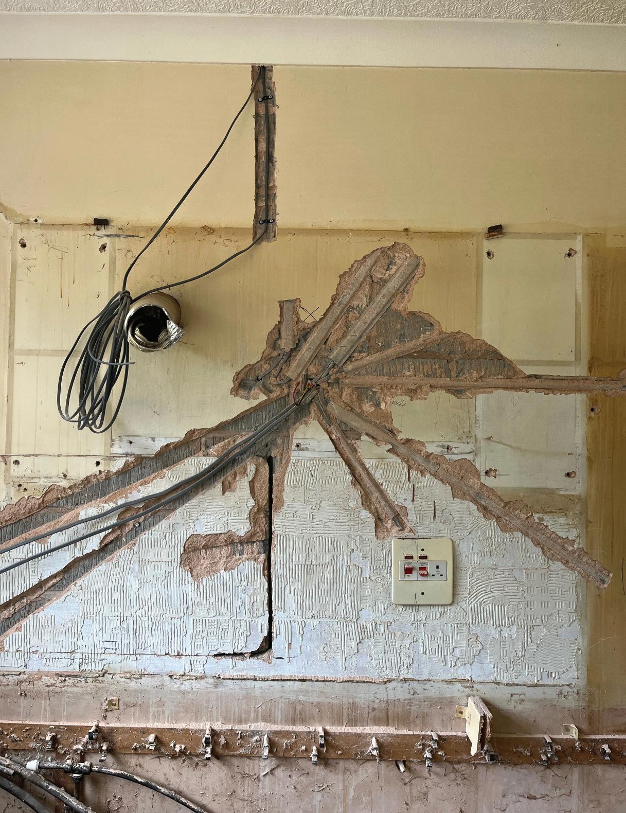
Observations, Regulation infringements and Codes applicable to this observation would be: Cables liable to damage, installed at a depth of less than 50mm from the surface of a wall not in safe zones
Need help with cracking those all-impor tant EICR codes? Ever y month the technical team at NAPIT will be studying your latest ‘Caught on Camera’ photos and offering advice on the next steps, should you find a similar installation. If you want the team at NAPIT to help crack your codes then send your pic tures through to us at: pe@hamer ville.co.uk
One of the biggest problems we face as an industr y is duty holders and clients not understanding the risks to them, their employees or the general public from poor electrical work. Dangers arising from unsk illed and shoddy work manship coupled with a lack of k nowledge and understanding of BS 7671 are risk ing lives
Here we have access to live par ts from the terminals of the connector block, not taken into an adequate enclosure, which may also have a mechanical strain on them from a lack of adequate containment for one of the cables connected to it.
Add to this the lack of mechanical protection for unsheathed and single -insulated cables, and we have the mak ings of a significantly dangerous modification to an existing installation
Even though LED strip lights of this type often do not require or have a facility for ear thing them, they must have mechanical protection for the supply cable, which is
usually a supplied flex. There is a requirement for cables to have a cpc throughout their length and be terminated at ever y point in the wiring, but that can be relaxed where the manufacturer supply cable is of a shor t length and not buried in a wall.
Installing this LED using a junction box and appropriate connecting flex would have been a simple and safe method, yet we find cost- cutting to the degree of danger a
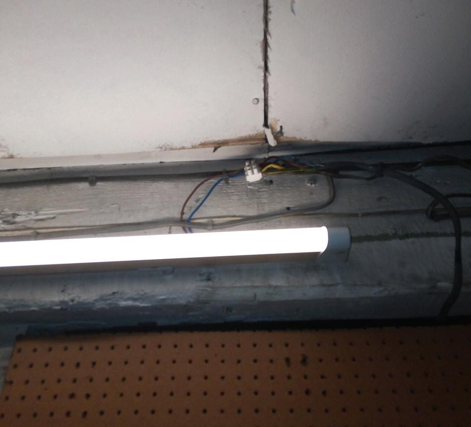
Duty holders and clients should always use a competent and registered installer to
protect themselves, their employees and the general public from these k inds of dangerous installation practices
The Observations, Regulation infringements and Codes applicable to this observation would be:
Access to live parts from terminal block screws not taken into an adequate enclosure
Possible strain on terminations from unsupported cable
Single insulation not taken into an adequate enclosure
LED light connection not connected in accordance with manufacturers instructions, exposing single-insulated cables
134.1.1, 416, 526.5
134.1.1, 526.6
134.1.1, 526.8
134.1.1, 526.8
The A2:2022 18th Edition Codebreakers publication is priced at £22.00 (members) and £24.00 (non-members). It is available in both hard copy and digital versions
MIKE GOHL: WE FOUND THIS WHILE REMOVING SOME LIGHTS, DUE TO THE RELOCATION OF A COMPANY THAT WANTED TO SAVE THE LED LIGHTS SHOCKING!
As an employer, at some point, you’ll ultimately have to deal with a worker who has lost a loved one, since grieving is inescapable
In situations like these, striking the right balance between protecting a worker's mental health and maintaining corporate operations may be tough. But what legal responsibility do employers have in these types of cases?

Bereavement and compassionate leave aren’t clearly defined under UK employment legislation (outside of statutory parental bereavement leave)
But employees do have the right to take ‘reasonable time’ off work to deal with problems involving ‘dependents’, such as a spouse, civil partner, child, parent, or anybody else who needs on their physical care, according to the Employment Rights Act of 1996
What constitutes ‘reasonable’ isn’t defined by law unless it is incorporated in an employment contract or a separate policy, however it is commonly regarded to be between two and five days. However, each case should be evaluated on its own

merits, taking into account the employee's relationship to the dead as well as the circumstances surrounding their death.
Employees who require additional time off beyond what has been agreed upon should do so as soon as possible Extensive bereavement leave is frequently unpaid and granted at the discretion of the employer Employers, however, should be aware of their legal obligation to protect an employee's well-being under the Health and Safety at Work Act 1974 and the Management of Health and Safety at Work Regulations 1999

This includes not rushing a return to work if mental health is an issue.
However, if the employee's lengthy absence is due to sadness or anxiety as a result of the bereavement, a fit note should be issued since the employee may be entitled to sick pay
Employers are responsible for ensuring that workers on bereavement leave aren’t treated unfairly The bereaved must be given the same opportunities for development or training as everyone else, and they cannot be fired simply because they’re physically absent If an employee believes they’ve been marginalised as a result of their absence, they may have grounds for a tribunal claim
When determining leave length, religious beliefs and customs must also be considered Under the Equality Act 2010, for example, denying an employee adequate time to undertake religious mourning rites might be deemed indirect discrimination
Under UK law, parents or primary carers who have lost a child under the age of 18 are treated differently People affected are entitled to two weeks of parental bereavement leave and/or statutory parental bereavement pay under the Parental Bereavement (Leave and Pay) Act.
a member of staff who has suffered a significant loss.“The bereaved must be given the same opportunities for development or training as everyone else, and they cannot be fired simply because they’re physically absent.”
Employees who have worked for at least 26 weeks previous to their bereavement are entitled to statutory bereavement pay of £156 66 per week, or 90% of their average weekly wages (whichever is lowest). Those who’ve not satisfied this service requirement are eligible for two weeks of unpaid parental bereavement leave
The legislation also protects the rights of employees who have a stillbirth after 24 weeks of pregnancy by providing them with 52 weeks of paid maternity leave.
During this time, the employee's usual job rights are also preserved, including the right to pay raises and accumulate annual leave
Some firms will have a unique bereavement policy in place to avoid unnecessary negotiations during a tough period
Such policies should state:
● How the time off will be handled;
● How much time off is reasonable to expect;
● What will be paid to the employee during bereavement leave;
● Procedures for reporting a bereavement;
● The employer's position if the deceased isn’t considered a ‘dependant’ under the Employment Act;
● How the return to work will be handled

Be mindful that a loss might cause substantial changes in a person's personal position, such as a change in childcare needs or greater financial demands
Employees may need to adjust their workload or tasks in order to manage their new circumstances.
The best approach to cope with this is to be flexible Part-time hours, flexible or hybrid working arrangements, or a phased return to responsibilities might all be recommended
Routine one-on-one meetings should be held after returning to work to track progress This ensures that any issues are brought to light as they develop Bereavement should be considered while conducting performance reviews to prevent unjustly damaging a person's work history
Empathy is necessary for effectively addressing a worker's bereavement The most practical way to show your support is to treat people in the same way that you’d like to be treated if the tables were turned The establishment of a safe and supportive environment for the bereaved will help to ensure their sustained participation, loyalty, and integration into the team
An arc fault detection device (AFDD) is a safety device which activates in the presence of series and parallel arc faults by monitoring the waveform (signature) of an arc It does this by electronically analysing the waveform and ‘trips’ when the waveform falls outside of predetermined values
The first Arc Fault Circuit Interrupter (AFCI) was patented in the US in 1980 and was described for use in the US National Electric Code (NEC) in 2008 In 2013 the Product Standard IEC 62606 was introduced and became a UK Standard that same year
BS EN 62606: 2013+A1: 2017 General requirements for arc fault detection devices states that the purpose of an AFDD is: ‘ to mitigate the risk of fire in final circuits of a fixed installation due to the effect of arc fault currents that pose a risk of fire ignition under certain conditions if the arcing persists’
The phenomena of electric arcing were first demonstrated to the Royal Society in
London by the chemist and inventor, Sir Humphrey Davy in 1801. Other studies followed and an electric arc can be considered to be:
‘An electrical breakdown of a gas that produces a prolonged discharge between two means of conduction ’
There are instances where arcing is a desired effect, such as when welding or plasma cutting However, uncontrolled arcing due to a fault is undesirable
Contact arcs can result from either direct or indirect contact between metal parts which are moving relative to one another or have little conductivity, such as a loose electrical connection or a break in conductor
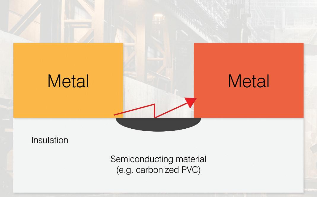
To generate an arc is a complicated process, but principally an arc fault is a function of the voltage and the distance between the two points of contact. Initially, an arc is composed of metallic vapours (for example, carbon) and current can flow through the damaged section
As the current flows through a material that is a relatively poor conductor, heat is built up due to the heating effect.
Whilst it is possible for a stable arc to be formed with low currents, say less than 2 A, there is insufficient energy to ignite the cable and hence, the probability of ignition is severely limited
Most arcing faults detected by an AFDD exist in currents ranging from 3 A to 10 A, and these values reflect normal operating currents in domestic installation circuits Causes of series arc faults vary but include damaged conductor cores and loose connections
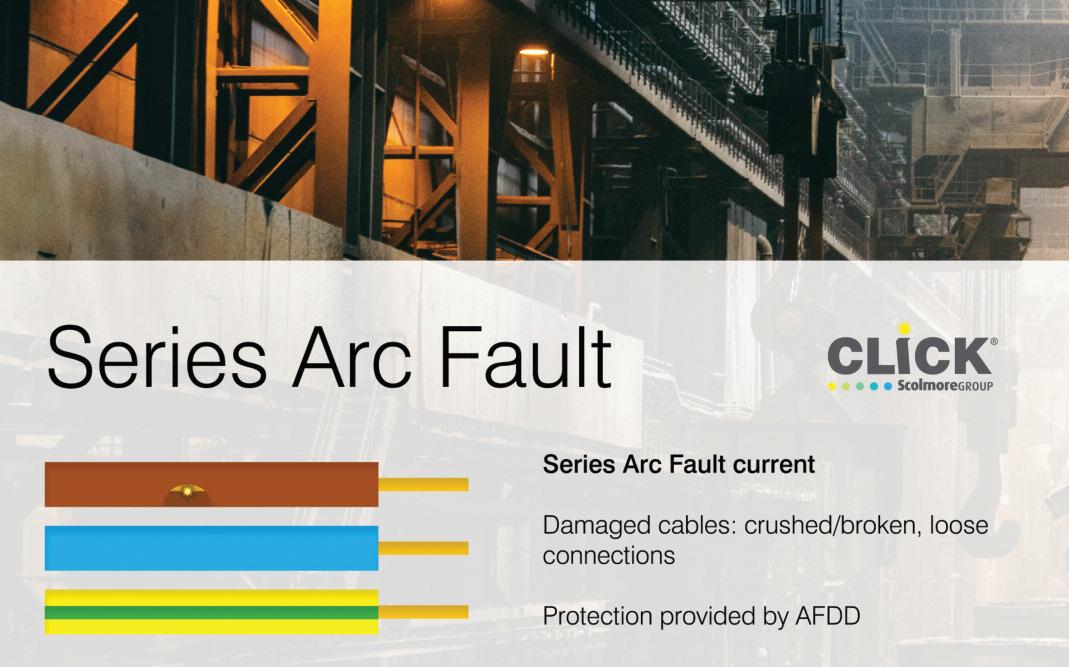
In a parallel arc, insulation breaks down between two or more conductive parts that are normally separated: line to neutral, line to earth and neutral to earth It is more likely that a parallel arc fault will operate a typical overcurrent protective device, such as a circuit-breaker or fuse than a series arc
Parallel arcs may be formed by tight bending radius of cables, twisting and bending of flex (perhaps by being trapped under a door), crushing, other mechanical damage and tracking.
AFDDs have been getting a lot of attention following the publication of Amendment 2 to BS 7671:2018. Jake Green, Technical Engagement Manager with Scolmore, looks at the technologies associated with AFDDs.
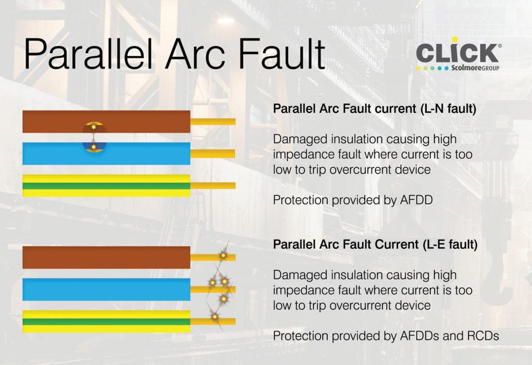
Manufacturers differ in how they choose to conform to the requirements of the Standard. Scolmore applies three characteristics in complex algorithms which, when taken together, will cause its AFDD to trip These are:
● Noise – HF noise in the high kHz to the MHz region. This ‘noise’ is generated by the movement of the arc roots at the cathode Whilst there are other sources of ‘noise’ which are naturally generated by electrical equipment operating normally, these are of a different nature and the algorithm filters them out
● Continuous – ‘noise’ must not be of a brief duration or very intermittent It is only a continuous process that will lead to the creation of a fire risk and, therefore, where ‘noise’ is intermittent
this will not lead to the operation of the AFDD.
● Current variation –erratic variations in current and waveform distorting the typical sinusoidal waveform of the normal supply A series arc will have an impact on the nature of the load current within a final circuit At the point of arcing there will be an increase in heating with a corresponding variation in current. The AFDD algorithm will sense this changing current
Unless all three elements are present the AFDD will not operate, as it is unlikely a true series or parallel arc will be present
Conclusion
It is well recognised that arcing can, and will, lead to fire An AFDD provides additional protection against fire and is particularly beneficial when protecting final circuits supplying socket-outlets
BROWSE THE ELUCIAN ONLINE PRODUCT CATALOGUE AT: WWW.RDR.LINK/EAS016
 Parallel Arc
One question that I have been asked numerous times over the years is: “How do I achieve selectivity in a residential property between a service cut-out fuse and a switch-fuse used for a sub-main without limiting the supply capacity considerably?”


This is a common situation concerning consumer units which are designed to be located in a different position to that of the intake position The electrician understands the supplier/DNO restrictions for consumers meter tail length and rightly

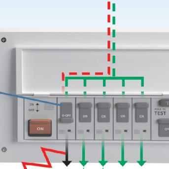
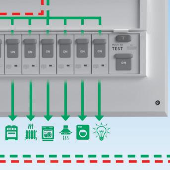
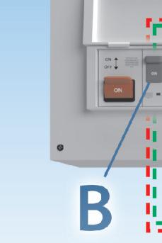
chooses to install a switch-fuse
In this article, I will explain how to achieve selectivity and discuss whether or not it’s actually required


Previously known as discrimination, selectivity is the ability of the protective device to operate in preference to another device, which is in a series connection configuration For correct device coordination, short-circuits, overcurrents and residual currents will need to be considered
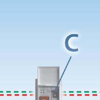
Fig 1 shows a scenario where four protective devices are installed in series (identified as A, B, C and D) as well as the position of a fault which has occurred downstream of protective device D In order to achieve selectivity, only the protective device immediately upstream of the fault should operate BS 7671 Part 2 also makes reference to partial selectivity and total selectivity, as follows:
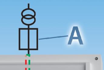
● Partial: Selectivity up to a given overcurrent lower than the breaking capacity of the downstream device
● Total: Selectivity for all overcurrents up to the value of the breaking capacity of the downstream device


Regardless of which aspect of coordination is being studied, BS 7671 provides general requirements for selectivity in Regulation group 536 4, as summarised below:
● Desk study utilising product standards and manufacturer’s literature, or
● The use of appropriate software in conjunction with manufacturer’s data, or
● Tests in accordance with the applicable product standards, or


● Manufacturer’s declaration
The worked example given in this article relates to device coordination between

NAPIT’s
Technical Author, Richard Townsend, takes a closer look at selectivity requirements for distribution circuits.Fig 1: Selectivity achieved with only protective device D operating With higher loading requirements in properties, supply capacity cannot always be reduced
fuses From this, it can be seen that it’s not just a case of simply stepping down one fuse size to achieve selectivity The actual characteristics of the devices used will need to be examined.
For the correct coordination between fuses, there are two aspects to consider:


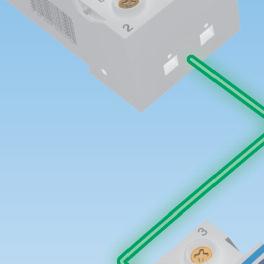


● Selectivity in the case of overloads, and
● Selectivity in the case of short-circuits.
For overloads, selectivity is validated by comparison of the time/current characteristics of the fuses concerned
We’re looking to ensure that the total operating time of the fuse positioned on the load side is lower than the pre-arcing time of the up-stream fuse on the supply side
For short-circuits, selectivity is validated by comparison of the I2t values As a designer, we are looking to achieve a maximum operating I2t value of the fuse positioned on the load side being lower than the minimum pre-arcing I2t value of the fuse on the supply side

Total selectivity can be achieved for most practical situations, where fuses are of the same utilisation category with a rated current of 16 A and above if a coordination ratio of 1.6:1 or greater is applied.
For example, an upstream fuse rated at 160 A will coordinate with a downstream fuse rated at 100 A
Worked example:


Using the coordination ratio 1 6:1, what fuse size is required for the switch-fuse, feeding the consumer unit sub-main? The service cut-out fuse is rated at 100 A
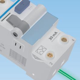


Answer:
100/1 6 = 62 5 A


In order to satisfy the 1.6:1 ratio, the sub-main fuse would need to be rated at 60 A to ensure total selectivity
Depending on the maximum demand for the installation, it’s likely that limiting the homeowner to 60% of their supply capacity will be unacceptable, especially with today’s trends requiring more loading
than ever, for example, by electric vehicles and heat pumps.
No, not in all cases Regulation 536 3 refers to coordination requirements and asks that the interaction between devices shall be considered so they do not affect the safety of the installation
For simple installations such as the example given in this article, there are no safety concerns regarding selectivity requirements not being met Let’s say you have selected a 100 A fuse for your sub-main supply; under fault conditions, if either fuse blows, there would be a bigger issue to worry about than selectivity.
The requirements of Regulation group 536 4, which outlines the requirements for selectivity, only need to be applied where the designer decides that selectivity is required Examples may be commercial installations where safety could be affected or processes disrupted.
Of course, if selectivity is called for as part of a specification or BS 7671 states that it shall be provided, it must be Regulation 711 536 4 1 4 is an example of where selectivity must be provided between RCDs for exhibitions, shows and stands.
The same general requirements can be applied as previously mentioned regarding the use of software, manufacturers’ checks, desk studies, etc. Selectivity, in the case of residual currents, is as follows:
● The upstream RCD should be suitably time delayed, and
● The ratio of upstream to downstream residual current rating should be at least 3:1.


See Fig 2, which illustrates these requirements
Conclusion

Where selectivity is required in any design, desktop studies using product standards may not provide the most accurate results The best approach will be contacting the protective device manufacturers, who provide tables based on tested results
Often manufacturers’ device selectivity figures offer the most accurate and sometimes more advantageous values than those found elsewhere
important, but often overlooked,
In simple terms, the ‘Maximum Demand’ of an electrical installation is the maximum amount of current it is ever likely to draw from its supply

This is expressed as a current in Amps in most cases, such as on EICs and EICRs, but for some installations it may be specified as a Power value in kilowatts or kVA
Maximum demand is addressed in Part 3 of the Wiring Regulations (Section 311), which states that for economic and reliable design of an installation the maximum demand shall be determined. This is an interesting, but important, use of these two terms and illustrates the balance that must be struck
Installing a huge supply that isn’t needed will not be cheap (economically) but installing a small supply when you know it will be inadequate will not be
reliable So, essentially, the electrician is tasked with determining the correct demand and then specifying the smallest supply capable of reliably delivering this The important point, though, is how?
Determining maximum demand can be achieved in many ways and each method has its pros and cons What they all have in common is that the more data you have about the installation and its usage the more accurate the final figure will be Before we look at the methods available to us, it’s worth adding a quick note on what we must avoid. Superficial and basically incorrect methods like just writing down the main fuse rating or simply adding up the current of all the MCBs are not based on the installation usage and are a sure sign that the electrician stating them has little idea what maximum demand is, or how a fuse works for that matter.
Given that maximum demand is based on gathering data about the installation and its usage, the Wiring Regulations also introduce the idea of ‘diversity’, and state that this must be used when determining maximum demand.
Diversity is the concept that not all circuits will be fully loaded at the same time, and if they are it will likely only be for a very short time It’s a sort of averaging effect and is the reason why just adding up all the MCB ratings is a bad idea, as it fails to consider diversity, resulting in an artificially high maximum demand
The method used often depends on the point at which the determination is being made, i e is it a design for a new installation before construction, before an addition or alteration to an existing
installation, or is it to evaluate the suitability of the supply, maybe as part of an EICR?
For a completely new installation we will have to rely heavily on calculation, using diversity values from Table A2 in the IET On-site Guide, or figures chosen by the designer based on their assumptions about how the installation is to be utilised
Calculation is, however, likely to be less accurate than measurement-based methods, and as with all design assumptions it is recommended that these are checked by measurement after the installation is complete This will confirm that they were indeed accurate within the tolerance required.
When assessing additions, alterations and existing installations we have the option to carry out measurements to determine the maximum demand with a greater degree of accuracy This is achieved by measuring the current (or power) consumed by the installation
This could be a single ‘spot’ reading taken with a clamp meter at the origin of the installation, but that will only show the current at that moment It is unlikely to represent the maximum and doesn’t show the full picture of demand over time.
The solution is to use a Power and Energy Logger, or PEL, which can log current and voltage over a given time –say a day, week or longer, dependent on the installation The PEL will record the installation current throughout this period and can be set to also record other parameters such as power and even harmonic content
This will give the designer a clear and highly detailed view of the usage of the
installation which can be used to assist in determining the true maximum demand Where micro-generation, such as PV, is installed a PEL can also allow you to factor this into the maximum demand
The current log shown with this article (bottom left) is typical for a 3-phase industrial installation and was performed over a week The current can be seen to peak at about 250 A Such detailed information enabled the designer to make an informed judgment about the maximum demand of this installation, with the PEL data and graphs to back up their decision.
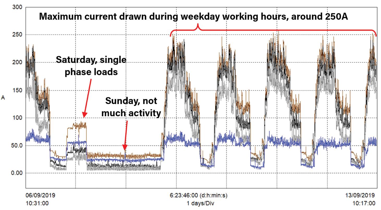
It is hard to imagine in a modern installation how this level of analysis could be achieved by calculation alone, making a PEL an almost essential piece of kit for all electricians

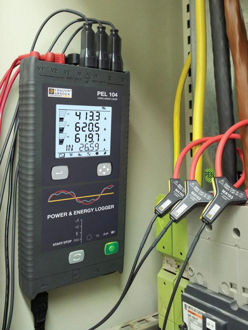
BROWSE CHAUVIN ARNOUX’S LATEST TEST AND MEASUREMENT BROCHURE AT: WWW.RDR.LINK/EAS017
SECTION 6
ENDS!
SCAN THE QR CODE TO CLAIM YOUR CPD CREDIT FOR THIS SECTION OR VISIT: WWW.RDR.LINK/EAS018

Here is a useful summary of all the adverts that appear in this special issue of Professional Electrician.
Taking place across two days, at six regional venues, ELEX is ‘The Electricians’ Exhibition’ Furthermore, we’ve got great news for visitors that are serious about their CPD!

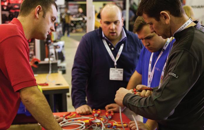
Recent changes to The Electrotechnical Assessment Specification (EAS) which sets out the minimum requirements for a business to be recognised as technically competent by a Certification or Registration Body, includes a requirement for businesses to maintain appropriate records of qualifications, training (including Continuing Professional Development) and experience.
To support this requirement, EVERY ELEX seminar is now CPD accredited, ensuring those individuals who make the time and effort to attend will receive a direct certificate of completion, which can
form a key part of your ongoing Continuing Professional Development record
With industry regulation and legislation changing constantly, the extensive ELEX seminar programme will cover an array of topics, including the latest Amendment 2 to the 18th Edition and the changes this covers, along with best practice and technical advice for professionals to get stuck into Presentations will be delivered by experts in their field and the only cost to delegates is their time
All seminars will take place in the IET Seminar Theatre located centrally in the exhibition hall and there’s no need for delegates to pre-book, just pre-register to attend the show
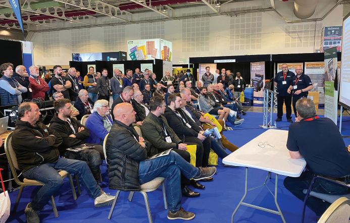
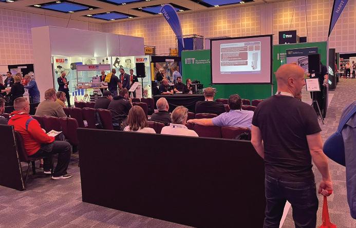
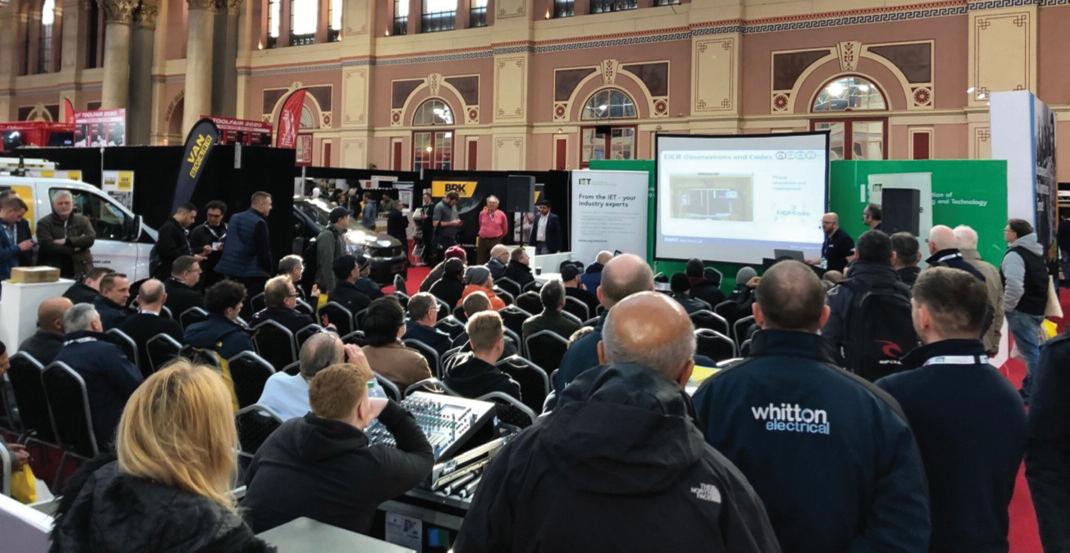
Whether you need some advice on the direction the sector is heading, want to chat with manufacturers about their latest solutions, view live demonstrations of the latest products or bag yourself a great
YOUR S H OW, NEA R YO U. . .
● At a venue near you
● Across two days
● Free parking (van friendly)
● Free entry
● Free T-Shirt & a free bacon roll* (*limited to first 1,000 visitors)
● Show bargains
● Hands-on demos
● Meet manufacturers
● Networking opportunities
● CPD accredited seminars and certificates

show deal on tools and equipment from leading brands, your regional ELEX tradeshow has it all
Make sure you check out the ELEX website to register for your free show ticket and to find out more about forthcoming venues and dates