PNEU-HYDRO CATALOG

Pneu-Hydro|

Gilmore’s line of Pneu-hydro flow control products provide cost effective solutions to the demands of high-spec hydraulic systems. Designed primarily for the energy sector, these versatile valves can be used in a wide range of applications and are designed and manufactured with the same quality for which Gilmore is known. The following list summarizes the product families within the Pneu-hydro line.
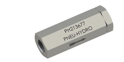
Gilmore’s Pneu-Hydro bar stock Check Valves seal bubble-tight, even without back pressure. Known for durability and reliable performance, these check valves provide a smooth flow-path with minimum resistance.

Gilmore’s Pneu-Hydro Right Angle Relief Valves remain bubble-tight up to cracking pressure and reseal bubble-tight at less than 10% drop from cracking pressure (significantly less in the higher pressure ranges). The external setting adjustment is particularly useful in applications where changes are required.
Gilmore’s Pneu-Hydro Inline Relief Valves remain bubble-tight up to cracking pressure. They reseal at less than 10% drop from cracking pressure in lower ranges, and less than 5% at higher ranges. Cracking pressure is reliable, repeatable, and easily set by an internal adjustment, which is tamper-proof once the valve is installed in the system.
Gilmore’s Pneu-Hydro Miniature Relief Valves provide zero leakage up to cracking pressure, and they reseal bubble-tight within 5 - 10% of cracking pressure. Adjustments are insensitive to temperature variations. Available in vent-to-connection or vent-toatmosphere configurations.


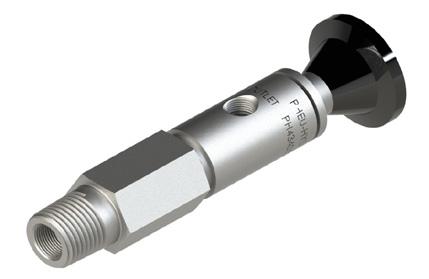
Gilmore’s Pneu-Hydro Quick-Vent Valves are designed to provide high flow rates from an actuator when supply pressure is vented, while also providing reliable and leak free performance under normal operation. This functionality reduces restrictions on actuators, providing more consistent and predictable hydraulic performance.
Gilmore’s line of Pneu-hydro flow control products provide cost effective solutions to the demands of high-spec hydraulic systems.
Designed primarily for the energy sector, these versatile valves can be used in a wide range of applications and are designed and manufactured with the same quality for which Gilmore is known. The following list summarizes the product families within the Pneu-hydro line.


Gilmore’s Pneu-Hydro Excess Flow Check Valves are designed to contain pressurized fluids in the event of catastrophic downstream failure. The spring-loaded poppet is held open during normal operation, permitting free flow in both directions, and automatically closes once a leak is detected and a pressure differential threshold is reached.
Gilmore’s Pneu-Hydro Hand Valves provide durable and precise flow control in a compact design. The Teflon stem packing and pintle swivel help to prevent contamination and washout while also ensuring reliable and effortless operation.


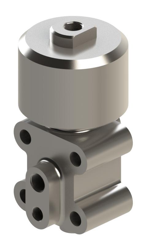
Gilmore’s Pneu-Hydro Interface Valves provide reliable pneumatic control over hydraulic functions up to 10,000 psi. These three-way two position valves are available in both normally open and normally closed versions.
Gilmore’s Pneu-Hydro HL-2 High-Low Pilot Valves are used to sense flow-line pressure and protect equipment from abnormal conditions. These adjustable valves can function as normally closed or normally open, controlling both pneumatic and hydraulic systems.
Gilmore’s Pneu-Hydro Pilot Valve Manifold assemblies utilize a pair of adjustable pilot valves to monitor flow line pressure. When a high or low limit is sensed, the assembly blocks and bleeds control pressure to provide fail safe shutdown of the system.


Gilmore’s line of Pneu-hydro flow control products provide cost effective solutions to the demands of high-spec hydraulic systems.
Designed primarily for the energy sector, these versatile valves can be used in a wide range of applications and are designed and manufactured with the same quality for which Gilmore is known. The following list summarizes the product families within the Pneu-hydro line.
Gilmore’s Pneu-Hydro Pneumatic Control Valves provide reliable control with pilot or manual push button control. These 3-way, 2-position valves are designed to select supply or vent to a function when actuated.
Gilmores’ Pneu-Hydro Shuttle Valves are used in systems where redundant or multiple supply sources are required. A simple ball and elastomeric seat design provides effec tive and reliable passive switching.


Gilmore’s Pneu-Hydro Sand Probe Valves provide a visual indication and a control system signal once a predetermined level of erosion has occurred in a flowline. These 2-way, 2-positon, normally open valves are piloted by flowline pressure entering the valves through an eroded opening in a sacrificial probe.
Gilmore’s Pneu-Hydro Inline Filters provide an effective and economic solution for filter ing control system fluid. These universal filters are equipped with replaceable elements available in several particulate size ranges.
Gilmore’s Pneu-Hydro Pressure Indicators provide a visual indication for the presence of pneumatic pressure.

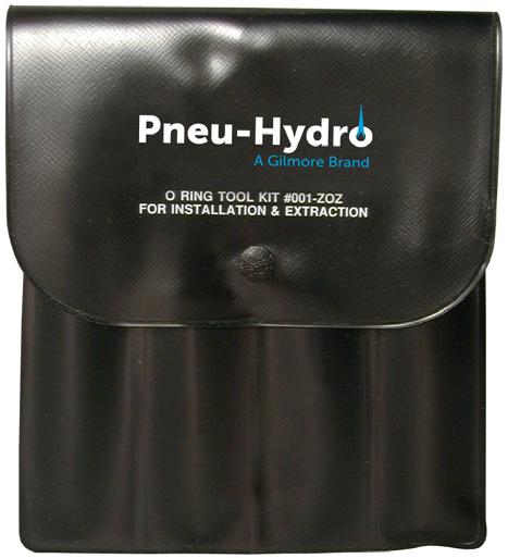
Gilmore's Pneu-Hydro kit of specifically designed tools for installing and extracting O-rings. Tools are invaluable to engineers, technicians and assembly personnel working on pneumatic, hydraulic and other fluid devices. They are fabricated from corrosion resistant materials for compatibility with most fluids and may be used in clean-room applications.
Gilmore's Pneu-Hydro check valves are constructed of 316 stainless steel for strength and corrosion resistance and meet the requirements of NACE MRO175. The poppet is spring loaded for positive operation regardless of orientation.

Back pressure and spring loads are carried by a metal stop rather than the o-ring to ensure long seal life and minimum maintenance.
• Smooth, chatter-free performance
• Reliable and repeatable cracking and reseating pressures
• Also available in Hastelloy, Duplex Stainless Steel, Inconel 625, Monel 400
• Standard seal materials are Buna-N and Viton
• Seal material selections are available for compatibility with virtually any fluid chemistry
Flow Coefficient (Cv) – 1/4” 0.55
Flow Coefficient (Cv) – 3/8” & 1/2” 1.3
Operating Temperature Range – Buna N Seals -40° F to 250° F

Operating Temperature Range – Viton Seals -20° F to 400° F
Hydrostatic Proof Pressure 15,000 psi
Part Number Dimensions (in)
Buna-N Viton Inlet Outlet L Hex
PH301F4Q PH301F4Q-V 1/4” NPTF 1/4” NPTF 2.28 0.75 PH301M4Q PH301M4Q-V 1/4” NPTM 1/4” NPTM 2.34 0.75
PH301M4F4Q PH301M4F4Q-V 1/4” NPTM 1/4” NPTF 2.25 0.75 PH301F6Q PH301F6Q-V 3/8” NPTF 3/8” NPTF 3.13 1.06 PH301M8Q PH301M8Q-V 1/2” NPTM 1/2” NPTM 3.63 1.06
Note: All models are designed for 5 psi cracking pressure. To order valves with the optional pressures shown above, add the indicated suffix number to the basic model number.
Crack pressure suffix number 2 psi -1 10 psi -2 25 psi -3
Repair Kit Part Number
PH613396
For Valve Part Number
For Valve Set Pressure Range
PH301F4Q, PH301M4Q, PH301M4F4Q 5 psi
PH613396-2 PH301F4Q-1, PH301M4Q-1, PH301M4F4Q-1 2 psi PH613396-10 PH301F4Q-2, PH301M4Q-2, PH301M4F4Q-2 10 psi PH613396-25 PH301F4Q-3, PH301M4Q-3, PH301M4F4Q-3 25 psi
Repair Kit Part Number
PH613396-V
For Valve Part Number
For Valve Set Pressure Range
PH301F4Q-V, PH301M4Q-V, PH301M4F4Q-V 5 psi
PH613396-2V PH301F4Q-1V, PH301M4Q-1V, PH301M4F4Q-1V 2 psi PH613396-10V PH301F4Q-2V, PH301M4Q-2V, PH301M4F4Q-2V 10 psi PH613396-25V PH301F4Q-3V, PH301M4Q-3V, PH301M4F4Q-3V 25 psi
Repair Kit Part Number
PH613581
For Valve Part Number
For Valve Set Pressure Range
PH301F6Q, PH301F6Q-1, PH301M8Q, PH301M8Q-1 2 & 5 psi
PH6133581-10 PH301F6Q-2, PH301M8Q-2 10 psi
PH613581-25 PH301F6Q-3, PH301M8Q-3 25 psi
Repair Kit Part Number
For Valve Part Number
For Valve Set Pressure Range
PH613581 -V PH301F6Q-V, PH301F6Q-1V, PH301M8Q-V, PH301M8Q-1V 2 & 5 psi
PH613581-10V PH301F6Q-2V, PH301M8Q-2V 10 psi PH613581-25V PH301F6Q-3V, PH301M8Q-3V 25 psi
Gilmore's Pneu-Hydro Right Angle Relief Valves are pressure balanced internally and pressure referenced to atmosphere. This yields insensitivity to downstream pressure and permits the valve to also be used as a back pressure regulator.

The valve seals against an elastomeric seat and utilizes a metallic positive stop to carry the spring load, prolonging seal life and ensuring reliable pressure relieving performance. The design provides full flow at a very small rise above cracking pressure.
Wide series of available relief pressure
Precise factory set relief pressure
Externally adjustable
Can be used as a back pressure regulator
Smooth, chatter-free performance
Reliable and repeatable cracking and
316 stainless steel construction
Maximum Allowable Working Pressure
10,000 psi
Flow Coefficient (Cv) – set range 100 – 5,000 psi 0.25
Flow Coefficient (Cv) – set range 5,000 – 10,000 psi 0.09
Operating Temperature Range – Buna N Seals -40° F to 250° F

Operating Temperature Range – Viton Seals -20° F to 400° F
Hydrostatic Proof Pressure
Connection - Inlet
Part Number
15,000 psi
1/4” Male NPT
Buna-N Viton Buna-N Viton
PH408M4F4Q-1 PH408M4F4Q-1V PH408M4Q-1 PH408M4Q-1V 100-150 psi (6.9 - 10.3 bar)
PH408M4F4Q-2 PH408M4F4Q-2V PH408M4Q-2 PH408M4Q-2V 150-250 psi (10.3 - 17.2 bar)
PH408M4F4Q-3 PH408M4F4Q-3V PH408M4Q-3 PH408M4Q-3V 250-350 psi (17.2 - 24.1 bar)
PH408M4F4Q-4 PH408M4F4Q-4V PH408M4Q-4 PH408M4Q-4V 350-600 psi (24.1 - 41.4 bar)
PH408M4F4Q-5 PH408M4F4Q-5V PH408M4Q-5 PH408M4Q-5V 600-900 psi (41.4 - 62.0 bar) PH408M4F4Q-6 PH408M4F4Q-6V PH408M4Q-6 PH408M4Q-6V 900-1,500 psi (62.0 - 103.4 bar) PH408M4F4Q-7 PH408M4F4Q-7V PH408M4Q-7 PH408M4Q-7V 1,500-3,000 psi (103.4-206.8 bar)
PH408M4F4Q-8 PH408M4F4Q-8V PH408M4Q-8 PH408M4Q-8V 3,000-5,000 psi (206.8-344.7 bar)
PH409M4F4Q PH409M4F4Q-V PH409M4Q PH409M4Q-V 5,000-10,000 psi (344.7-689.5 bar)
Repair Kit Part Number
PH613369-1
For Valve Part Number
For Valve Set Pressure Range Spring Color
PH408M4F4Q-1 100 - 150 psi (6.9 - 10.3 bar)
Violet
PH613369-2 PH408M4F4Q-2 150 - 250 psi (10.3 - 17.2 bar) Black
PH613369-3 PH408M4F4Q-3 250 - 350 psi (17.2 - 24.1 bar) Yellow
PH613369-4 PH408M4F4Q-4 350 - 600 psi (24.1 - 41.4 bar) Yellow
PH613369-5 PH408M4F4Q-5 600 - 900 psi (41.4 - 62.0 bar) Dark Green
PH613369-6 PH408M4F4Q-6 900 - 1,500 psi (62.0 - 103.4 bar) Dark Green
PH613369-7 PH408M4F4Q-7 1,500 - 3,000 psi (103.4 - 206.8 bar) Dark Blue
PH613369 PH408M4F4Q-8 3,000 - 5,000 psi (206.8 - 344.7 bar) Red
PH613416 PH409M4F4Q 5,000 - 10,000 psi (344.7 - 689.5 bar) Light Orange
Repair Kit Part Number
PH613369-1V
For Valve Part Number
For Valve Set Pressure Range Spring Color
PH408M4F4Q-1V 100 - 150 psi (6.9 - 10.3 bar) Violet
PH613369-2V PH408M4F4Q-2V 150 - 250 psi (10.3 - 17.2 bar) Black
PH6 13369-3V PH408M4F4Q-3V 250 - 350 psi (17.2 - 24.1 bar) Yellow
PH6 13369-4V PH408M4F4Q-4V 350 - 600 psi (24.1 - 41.4 bar) Yellow
PH6 13369-5V PH408M4F4Q-5V 600 - 900 psi (41.4 - 62.0 bar) Dark Green
PH613369-6V PH408M4F4Q-6V 900 - 1,500 psi (62.0 - 103.4 bar Dark Green
PH613369-7V PH408M4F4Q-7V 1,500 - 3,000 psi (103.4 - 206.8 bar) Dark Blue
PH61 3369-V PH408M4F4Q-8V 3,000 - 5,000 psi (206.8 - 344.7 bar) Red
PH61 3416-V PH409M4F4Q-V 5,000 - 10,000 psi (344.7 - 689.5 bar) Light Orange
Gilmore’s Pneu-Hydro Inline Relief Valves provide reliable performance in a compact package with a wide range of available relief set points.

Utilizing an elastomeric O-ring seal on the poppet and a metallic positive stop to carry the spring pre-load, this simple design provides reliable settings, predictable performance, and prolonged service life. The standard valve is constructed of 316 stainless steel for strength and durability in the most corrosive applications.
• Wide set range from a single part number
• Precise factory set relief pressure per customer specification
• Relief pressure easily set by internal adjustment
• Tamper proof adjustment
• Smooth, chatter-free performance
• Reliable and repeatable cracking and reseating pressures
• Standard seal materials are Buna-N and Viton
• Seal material selections are available for compatibility with virtually any fluid chemistry
Operating Pressure Range - Type 401 50 - 3,000 psi
Operating Pressure Range - Type 402 3,000 – 10,000 psi
Operating Temperature Range – Buna N Seals -40° F to 250° F
Operating Temperature Range – Viton Seals -20° F to 400° F
Part Number Connections Cv Length (In) Hex (In) Pressure Range (psi) Dash #

PH401F6Q-
3/8” NPTF 1.3 4.25 1.38
PH401F8Q- 1,2 1/2” NPTF 1.3 4.61 1.38
PH401M4Q- 1,2 1/4” NPTM 0.6 3.5 0.94
PH401F4Q- 1,2 1/4” NPTF 0.6 3.0 0.94 50-250 250-600 500-1,750 1,500-3,000
-1 -2 -3 -4
PH402F4Q- 2 1/4” NPTF 0.6 4.5 1.38 3,000-10,000 N/A
PH402F8Q-
NPTF 0.6 4.67 1.38 3,000-10,000 N/A
Repair Kit Part Number For Valve Part Number Pressure Range (psi) Dash # Spring Color
PH613652- 1,2 PH401F6Q
50-250 250-600 500-1,750 1,500-3,000
-1 -2 -3 -4
Lt Green Brown Brown Uncoated PH401F8Q
PH614114- 1,2 PH401F4Q
50-250 250-600 500-1,750 1,500-3,000
-1 -2 -3 -4
Yellow Uncoated PH401M4Q Red Uncoated
PH613760- 2 PH402F4Q PH402F8Q 3,000-10,000 N/A Uncoated
MODELS
VENT TO ATMOSPHERE
and

Standard models are constructed of 316 stainless steel for strength and durability in the most corrosive applications, with additional material options available. Buna-N or Viton O-rings are standard with other sealing materials available.
• Wide set range from a single part number
• Precise factory set relief pressure per customer specification
• Relief pressure easily set by external adjustment
• Smooth, chatter-free performance
• Reliable and repeatable cracking and reseating pressures
• Standard seal materials are Buna-N and Viton
• Seal material selections are available for compatibility with virtually any Fluid chemistry
• Ported vent models (PH405 and PH407) have 1,000 psi rated vent ports
and
HEX
Operating Pressure Range - Type 404 and 405 50 - 5,000 psi
Operating Pressure Range - Type 406 and 407 5,440 – 13,000 psi
Connection - Inlet 1/4” NPT M

Connection – Vent (Type 405 and 407) 1/4” NPT M
Operating Temperature Range – Buna N Seals -40° F to 250° F
Operating Temperature Range – Viton Seals -20° F to 450° F
Cv – Type 404, 405, 406, 407 0.035
Part Number Vent Type Length (In) Hex (In) Pressure Range (psi) Dash #
PH404M4Q-
4.61 1.38
PH405M4Q
3.5 0.94
50-100 100-150 150-250 250-350 350-600 600-900 900-1,500 1,500-3,000 3,000-5,000
-10 -1 -2 -3 -4 -5 -6 -7 -8
Atmosphere 4.5 1.38 5,000-13,000 N/A N/APH407M4Q
PH406M4Q
4.67 1.38
Repair Kit Part Number For Valve Part Number Pressure Range (psi) Dash # Spring Color
PH613376- 1,2
PH404M4Q PH405M4Q
50-100 100-150 150-250 250-350 350-600 600-900 900-1,500 1,500-3,000 3,000-5,000
-10 -1 -2 -3 -4 -5 -6 -7
Purple Violet Black
Green
Blue
Lt Orange
PH613374- 2 PH406M4Q PH407M4Q 5,000-13,000 N/A Uncoated
OUTLET
Gilmore’s Pneu-Hydro Quick Vent Vales are constructed of 316 stainless steel for strength, durability and in accordance with NACE MR-01-75.

material options are available. Buna-N or Viton O-rings are standard with other sealing materials available.
Features & Benefits
Smooth, chatter-free performance
316 stainless steel construction
seal
Maximum Allowable Working Pressure
Connection - Inlet

psi
NPT F
Connection - Outlet
Operating Temperature Range - Buna N Seals
Operating Temperature Range – Viton Seals -20°
Cv - Supply to Function
- Function to Vent
Part Number Seal Type
PH433254 Buna-N PH433254-V Viton
Part Number Seal Type
PH613254 Buna-N
PH613254-V Viton
NPT F
NPT F Connection - Vent
F to 250° F
to 450°
Gilmore’s Pneu-Hydro Excess-Flow Check Valve are designed not only to prevent fluid loss in the event of a downstream failure but will also remain closed as long as supply pressure is maintained.
Constructed of 316 stainless steel for strength, durability and in accordance with NACE MR-01-75. Suitable for use with liquids or gasses.

• Flow is normally permitted in both directions through the valve
• In the event of a down-stream failure causing an imbalance in pressure, the poppet will close preventing escape of fluid until system repair
• The spring will reset the poppet to its open position after the removal of supply pressure for system maintenance

Gilmore’s Pneu-Hydro Hand Valves include many features designed specifically to improve the durability and performance, while also minimizing the overall size.

A strategically placed packing below the stem threads help to ensure a durable and leakproof seal, and a self-aligning swivel pintle aids in minimizing seat scoring. A very low operating torque (less than 10 lb-inches) provides a precise ‘feel’ and adjustment sensitivity over the lifetime of the valve. The valve stem is designed so that it cannot be inadvertently backed out of the valve, and the low profile makes this valve ideally suited for panel mounted or other limited space applications. Teflon stem seal and 316 stainless steel construction combine to provide maximum compatibility with corrosive fluids.
• Self-aligning swivel pintle to minimize seat scoring
• Teflon stem seal and 316 stainless steel construction to provide maximum compatibility with corrosive fluids
• Weight = approx .5 lbs

Maximum Allowable
Maximum Allowable
Proof Pressure
PH206F4Q
PH202M4F4Q
PH202F4Q
1.93
Gilmore’s Pneu-Hydro Interface Valves utilize a piston style pneumatic actuator to control a three-way two position hydraulic valve. Configured in both normally open and normally closed versions, these valves can accommodate hydraulic pressures up to 10,000 psi and pilot pressures up to 1,000 psi.
The unique spool valve design permits the use of a piston style actuator, eliminating the common failures and leakage associated with pilot diaphragms, while also ensuring safe and reliable operation with consistent low pilot pressure; 50 psi pilot at 5,000 psi hydraulic, and 80 psi pilot at 10,000 psi hydraulic.

A combination of elastomeric and metal seals ensures reliable zero leakage performance in the hydraulic power section. Failsafe closure is ensured, as both the internal spring and hydraulic pressure acting on the differential spool area provide sufficient force to effect closure should one or the other fail.
A positive indicator of operation is provided in the spool extension, which shifts to show position, and the manual override version has a turning handle located at the top center of the piston housing.
Excellent flow capacity is provided with a value of Cv = 0.5 or the equivalent of an orifice of 0.224 inch diameter.
Operating Pressure
Hydraulic or Air
50 psi with 5,000 psi hydraulic 80 psi with 10,000 psi hydraulic
Maximum Allowable Working Pressure 1,000 psi
Proof Pressure
1,500 psi
Burst Pressure 2,000 psi
Connection
1/4” NPT F
Control Fluid Hydraulic or diesel
Maximum Allowable Working Pressure 10,000 psi
Proof Pressure 15,000 psi
Burst Pressure 20,000 psi
Temperature Range
-65° F to 450° F Flow Capacity (Cv) 0.5
Flow Rate 39 Gal/min @ 5,000 psi
Connection
Part Number Description
183834-P
1/4” NPT F
Valve, hydraulic interface 3-wnc 6k psi manual override
433174-P Valve, hydraulic interface 3-wnc 6k psi 433174-PA Valve, hydraulic interface 3-wnc 6k psi arctic 433174-PH Valve, hydraulic interface 3-wnc 8k psi hydraulic pilot
433174-PHA Valve, hydraulic interface 3-wnc 8k psi hydraulic pilot arc 433242-P Valve, hydraulic interface 3-wno 6k psi 433242-PH Valve, hydraulic interface 3-wno 6k psi hydraulic pilot
433242-PHA Valve, hydraulic interface 3-wno 6k psi hydraulic pilot arctic
433707-P Valve, hydraulic interface 3-wnc 6k psi dual inlet 433707-PH Valve, hydraulic interface 3-wnc 6k psi dual inlet arctic
434189 Valve, hydraulic interface 3-wnc 10k psi
434189-A Valve, hydraulic interface 3-wnc 10k psi arctic
Repair Kit Part Number
For Valve Part Number
PH613174-P PH433174-P
PH613174-PA PH433174-PA
PH613174-PH PH433174-PH
PH613174-PHA PH433174-PHA
PH613242-P PH433242-P
PH613242-PH PH433242-PH
PH613707-P PH433707-P
PH613707-PH PH433707-PH
PH613834-P PH183834-P
PH614189 PH434189
Gilmore’s Pneu-Hydro HL-2 High-Low Pilot Valves rely on flowline pressure to pilot an adjustable control valve. Capable of functioning as either normally open or normally closed, these 3-way control valves are intended to initiate a shutdown when flowline pressure is sensed to exceed a low or high setpoint.
Available in eight pressure ranges up to 10,000 psi, and with a wide range of available alloys and seal materials, these valves are compatible with any flowline fluid, and can be safely used in both hydraulic and pneumatic control systems.

• Wide series of available pressure ranges
• Smooth, chatter-free performance
• Reliable and repeatable cracking and reseating pressures
• 316 stainless steel construction (Also available in Hastelloy, Duplex Stainless Steel, Inconel 625, Monel 400)
• Seal material selections are available for compatibility with virtually any fluid chemistry
• Repeatability of set point = 1% of full range max
• Dead Band = 10% of full range max
• Weight = Approx 2.8 lbs
Maximum Allowable Working Pressure - Flowline 10,000 psi

Maximum Allowable Working Pressure - Controls 150 psi Operating Temperature -20° F to 400° F
Part Number Standard/H2S-CO2
Part Number Artic Service Pressure Range

PH433741 PH433741 5 - 50 psi (.34 - 3.4 bar)
PH433742 PH433742 30 - 115 psi (2.1 - 7.9 bar)
PH433744 PH433744 100 - 1,000 psi (6.9 - 68.9 bar)
PH433745 PH433745 500 - 1,500 psi (34.5 - 103.4 bar)
PH433743 PH433743 1,000 - 5,000 psi (68.9 - 344.7 bar)
PH433746 PH433746 1,500 - 3,500 psi (103.4 - 241.3 bar)
PH433730 PH433730 3,000 - 6,000 psi (206.8 - 413.7 bar)
PH433747 PH433747 5,000 - 10,000 psi (344.7 - 689.5 bar)
Repair Kit Part Number For Valve Part Number
PH613730 PH433730
PH613741 PH433741
PH613742 PH433742
PH613743 PH433743
PH613744 PH433744
PH613745 PH433745
PH613746 PH433746
PH613747 PH433747
Gilmore’s Pneu-Hydro High-Low Manifold Pilot Valve Assembly combines two HL-2 pilot valves into a compact manifold assembly to provide reliable monitoring of flowline pressure. Using any combination of two HL-2 valves, limit pressures can be set to any range between 5 and 10,000 psi.
Through a common flowline pressure sensed in the manifold, the HL-2 valves can be set to block and bleed the control fluid or switch to open the control source when pressures are detected to be beyond a low or high pressure set point.

• Wide series of available pressure ranges
• Smooth, chatter-free performance
• Reliable and repeatable cracking and reseating pressures
• 316 stainless steel construction (also available in Hastelloy, duplex stainless steel, Inconel 625, Monel 400)
• Seal material selections are available for compatibility with virtually any fluid chemistry
DRILLING
Control Fluid
Hydraulic or Air
Allowable Working Pressure - Flowline 10,000 psi
Allowable Working Pressure - Controls
Temperature
Sense Port
Pilot Ports
Test Ports
Section Maximum Pressure Part Number Pressure Range
A
psi
F to
1/2" NPT
1/4" NPT
1/2" NPT
High pilot digits 1&2 Low pilots digits
1,500 psi PH433741 5 - 50 psi (.3 - 3.4 bar)*
1,500 psi PH433742 30 - 115 psi (2.0 - 7.9 bar)*
10,000 psi PH433744 100 - 1,000 psi (6.9 - 68.9 bar)
10,000 psi PH433745 500 - 1,500 psi (34.4 - 103.4 bar)
10,000 psi PH433746 1,000 - 5,000 psi (68.9 - 344.7 bar)
10,000 psi PH433743 1,500 - 3,500 psi (103.4 - 241.3 bar)
10,000 psi PH433730 3,000 - 6,000 psi (206.8 - 413.7 bar)
10,000 psi PH433747 5,000 - 10,000 psi (344.7 - 689.5 bar)
High-Low Pilot Manifold Assemblies are ordered under a nine-digit part number starting with PH876-63-, followed with digits 1&2, and 3&4 from the table above. For optimal performance, both the high range and low range valves should be selected from the same section in the table above.

Example: P/N PH876-63-0503 (high set range 1,500 - 3,000 psi; low set range 100 - 1,500 psi (For Artic Service add "-A" at the end of the assembly requirement. Example: PH876-63-0301-A)
PH876-63-0301
PH876-63-0302
PH876-63-0303
PH876-63-0402
PH876-63-0403
PH876-63-0502
Pilot Manifold, HL-2, 100-1000 PSI, 5-50 PSI, CF8M
Pilot Manifold, HL-2, 100-1000 PSI, 30-115 PSI, CF8M
Pilot Manifold, HL-2, 100-1,000 PSI, 100-1,000 PSI, CF8M
Pilot Manifold, HL-2, 500-1,500 PSI, 30-115 PSI, CF8M
Pilot Manifold, HL-2, 500-1,500 PSI, 100-1,000 PSI, CF8M
Pilot Manifold, HL-2, 1,500-3,500 PSI, 30-115 PSI, CF8M
Pilot Manifold, HL-2, 1,500-3,500 PSI, 100-1,000 PSI, CF8M PH876-63-0504
PH876-63-0503
Pilot Manifold, HL-2, 1,500-3,500 PSI, 500-1,500 PSI, CF8M PH876-63-0603
Pilot Manifold, HL-2, 1,000-5,000 PSI, 100-1,000 PSI, CF8M PH876-63-0606
Pilot Manifold, HL-2, 1,000-5,000 PSI, 1,000-5,000 PSI, CF8M PH876-63-0806
Pilot Manifold, HL-2, 5,000-10,000 PSI, 1,000-5,000 PSI, CF8M PH876-63-0808
Pilot Manifold, HL-2, 5,000-10,000 PSI, 5,000-10,000 PSI, CF8M
Gilmore’s Pneu-Hydro Pneumatic Control Valves provide control over two pneumatic sources to a single function. With manual or piloted control, these versatile and robust valves provide reliable, bubble-tight sealing for a wide range of applications.
Options for line, panel or bracket mounting configurations provide a solution for almost all installations.
316 stainless steel construction

Broad selection of o-ring materials
Compact design
Air
Maximum Allowable Working Pressure 250 psi Cv .40

Operating Temperature -20° F to 450° F
Part Number Description
Repair Kit Part Number
PH183552 Panel Mounted, pushbutton PH613612
PH183554 Bracket Mounted, pushbutton PH613612
PH183612 Line Mounted, pushbutton PH613612
PH433553 Bracket Mounted, pilot operated PH613612
PH433555 Line Mounted, pilot operated PH613612
PH434150 Panel Mounted, pilot operated PH614150
Gilmore’s Pneu-Hydro Shuttle Valves provide reliable passive switching for control systems with multiple and/or redundant supply sources.

The simple yet durable ball valve design eliminates breakaway friction, common with sliding seal designs, allowing the valves to switch sources with very low differential pressure. Primarily used in pneumatic control systems, these shuttle valves will also operate in low pressure hydraulic systems.
stainless steel
Maximum Allowable Working Pressure 250 psi
Operating Temperature - Buna
Operating Temperature - Viton
Buna Viton
PH801F4Q PH801F4Q-V

Repair Kit Part Number For Valve Part Number
PH613258-1 PH801F4Q
PH613258-2 PH801F4Q-V
to 250°
to
A carefully designed sensing probe extends into the flow path, providing a hydraulic pilot signal to the Sand Probe Valve. Once a predetermined amount of erosion opens a hydraulic communication path within the probe, the normally open valve shifts to block and bleed pneumatic control pressure, providing a signal suitable to close a flowline valve, trigger an alarm, or initiate a shutdown.
The sensing pilot is designed with a 1/2” NPT male thread for attachment to the flowline. Within this connection, is another 1/4” NPT female connection for the tubular probe. With this arrangement, probes can be readily fabricated and installed in the field from standard fittings and tubing.

Wide pressure range: This device may be safely operated in flowlines containing pressures in the range of 25 - 10,000 psi (1.72 - 689.47 bar)
Control pressure range: The pilot handles a control system pressure of 20 - 250 psi (1.37 - 17.23 bar)
Visual indicator: When the probe has been cut and the pilot spool shifts, the palm button and red band on the main spool indicate that the pilot has been activated
Manual Control: The palm button on the pilot may be used at any time to cycle the valve and test the system
Simplicity: When the probe has been cut by abrasive action of the flowing product, the pressure in the pipeline shifts the pilot spool
Choice of probes: Standard wall probes are available in thicknesses of 0.028; 0.035; 0.049 and 0.065 inches. Standard length probes are 6, 10 and 14 inches
Maximum Allowable Working Pressure - Flowline 10,000 psi
Maximum Allowable Working Pressure - Controls 250 psi Operating Temperature -20° F to 450° F

Part Number* Maximum Operating Pressure Ranges Repair Kit Part Number
PH434051 30 -250 psi (2.07 - 17 bar) PH614051 PH434052 250 - 10,000 psi (17 bar - 689 bar) PH614052 PH434062 PH614062
*Valves and probes are ordered separately. Model numbers above do not include probes.
Prob Length* (inches)
Probe Wall Thickness (inches)* 0.028 0.035 0.049 0.065 6 08-03756-01 08-03756-02 08-03756-03 08-03756-04 10 08-03756-07 08-03756-08 08-03756-09 08-03756-10 14 08-03756-11 08-03756-12 08-03756-13 08-03756-14
*Select the probe length and thickness from the probe kit chart above.
These filters are designed to use a strong, durable element, with a large surface area that reduces the need for frequent cleaning or replacement. A unique assembly retains the filter element solidly, preventing flutter; yet it is easily removed for cleaning or replacement. It will not contribute to system pulsation. A variety of filtration ranges are available.

Maximum Allowable Working Pressure
Operating Temperature
Inlet
Part Number Filtration Size (μm) Repair Kit (Element + Gasket)
PH511F4Q-2 2 PH613511-2
PH511F4Q-5 5 PH613511-5
PH511F4Q-20 20 PH613511-10
PH511F4Q-40 40 PH613511-20

PH511F4Q-50 50 PH613511-40
PH511F4Q-100 100 PH613511-100
Gilmore’s Pneu-Hydro Pressure Indicator offers easy to read visual notification of the presence or absence of pneumatic pressure in a control circuit.

When pressure rises to approximately 1 bar (14 psi), a solid green band shows through the window.
If the pressure drops below 0.5 bar (8 psi), a red and white striped band appears. The colors are reflective for visibility in lighted surroundings. The striped section provides added recognition of system status under dimly lit conditions or when color cannot be distinguished.
• The unit mounts through a 1.75 in. diameter hole and in panels from 17 gauge to 0.18 in. thick
• The indicator is constructed of 316 stainless steel and satisfies NACE MRO175 standard
Maximum Allowable Working Pressure 250 psi
Proof Pressure 500 psi
Part Number 1/8" NPT Connection
Part Number 1/4" NPT Connection
Buna-N Ethylene Viton Buna-N Ethylene Viton PH433774-A PH433774-EPDM PH433774 PH433775-A PH433774-EPDM PH433775
Operating Temperature Ranges
Buna-N Seals Viton Seals
Ethylene Propylene Seals -40°F to 250°F -20°F to 400°F -65°F to 300°F

Buna-N
Ethylene Propylene Viton PH613774-A PH613774-EPDM PH6613774
Pointed prying tool - 462688-1
Piercing tool - 462688-2
Tweezers - 462688-3
Jogging/prying tool - 462688-4
Prodding/removal tool - 462688-5
Vinyl pouch - 462688-6
Instruction sheet - 462688-7