Building Performance Information Renewables UI Reports CHPS
CHPS Sections & Exhibits
CHPS Scorecard
Systems Narrative - Structural
Systems Narrative - Mechanical
Systems Narrative - Electrical
Systems Narrative - Plumbing
Systems Narrative - Fire Protection
Systems Narrative - Audiovisual
Systems Narrative - Food Service
Systems Narrative - Telecommunications
Executive Summary
Ann Arbor Public Schools (AAPS) District was founded in 1905 and serves the City of Ann Arbor, MI and eight surrounding townships, covering 125 square miles. AAPS educates approximately 16,815 students in 32 schools and one on-line academy. AAPS has a diverse student body representing 85 counties and 64 different languages.
The District’s buildings were built around 1992 and various years up through 2008. With an average age of 64 years, it was time to ready the district’s facilities for the 21st century and beyond. In November 2019, the community voted to approve a $1 billion bond referendum to build new, replace, and renovate school facilities.
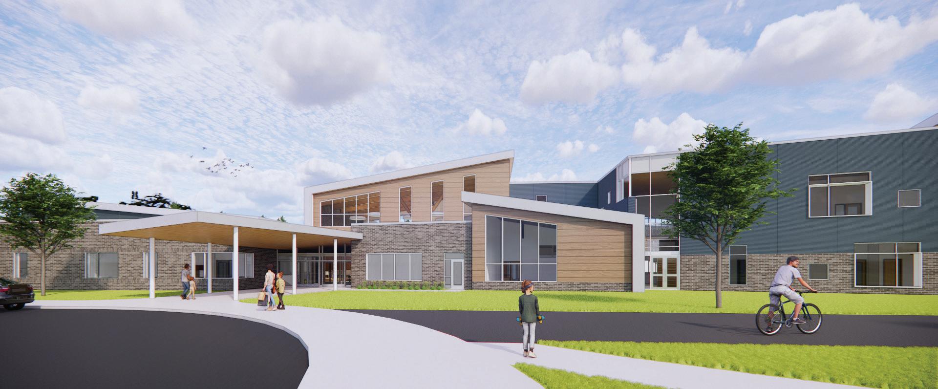
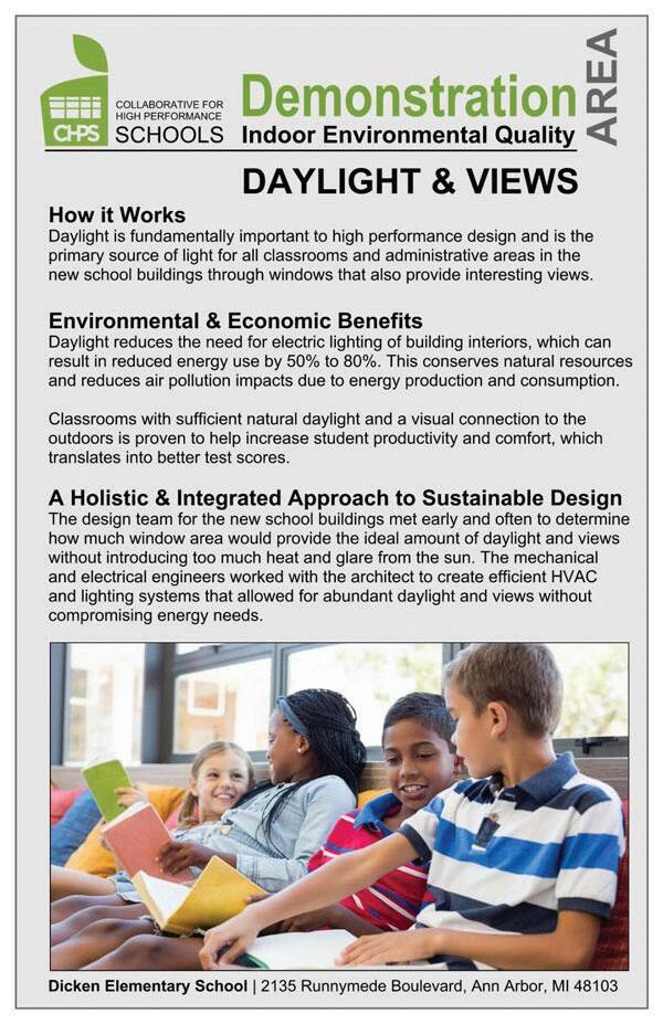
Dicken Elementary School
As part of the first 10-year construction phase, the existing Dicken Elementary School, located at 2135 Runnymede Blvd., Ann Arbor, MI 48103 was programmed to be demolished and replaced with a new school on the same 12 acre site. The new school is targeted to be completed by Fall 2027 and occupied prior to the existing school being demolished.
The new Dicken Elementary School is being designed as a two-story, 64,000 sf building to accommodate the current enrollment of approximately 350 students with spaces sized to for a future potential enrollment up to 420 students if the need arises. The new school design is being developed as a student-centric environment for modern teaching and learning including the use of a CHPS (Collaborative for High Performance Schools) framework for a healthy, environmentally friendly facility. The design will incorporate the following district goals:
District Overall Facility Goals
• Teaching & Learning – Continue the Tradition of Academic Excellence
• Safety, Health & Well-being – Focus on Development of the Whole Child
• Efficient & Effective Support Systems & Services – Continue Technology & Transportation Replacement and Renewal
#1 VALUES | VISIONING AND SUSTAINABILITY
Early March 7, 2023
Lead Sustainability VALUES Workshop
Synthesize top VALUES for Dicken
Create Values and CHPS Report to guide design
Report to inform BOLD
#2 BOLD | MODERN LEARNING
March 22, 2023
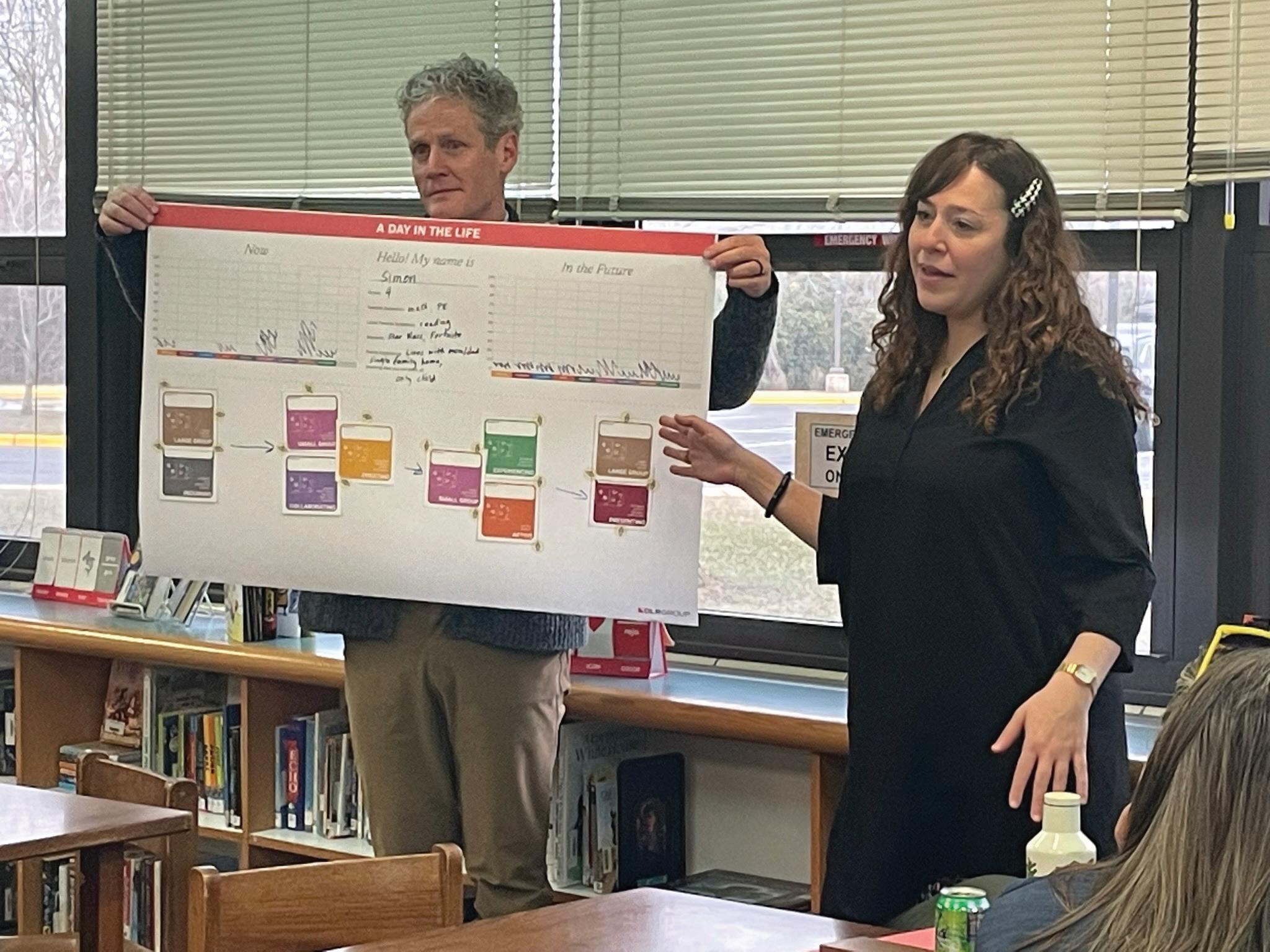
Education, Evaluation, Encactment Day in the Life
Discuss existing teaching methods, planned changes, and affect design
Brainstorm potential space program and design needs rooted in teaching and learning
#3 CURRICULUM | TEACHING & SPACE ALIGNMENT
April 13, 2023
Compare space program needs to outcomes from VALUES and BOLD
Verify quantity and size of space combinations
Explore different spatial relationships to serve teaching and learning outcomes
#4 DESIGN CONCEPT | THEME
May 9, 2023
Compare design options to outcomes from VALUES, BOLD and CURRICULUM
Layer design themes over space programs
Explore design options to support sustainability goals
Choose design options that create opportunities for building as teaching tool
VALUES stands for Viewing Architecture through the Lens of User Experience and Sustainability. This approach focuses on how sustainable design solutions impact the way users interact with and experience their surroundings.
stands Architecture of and Sustainability. focuses on how sustainable design solutions impact the way users interact with and experience their surroundings.
A VALUES session is an important planning and project visioning session used to establish sustainability and wellness goals, while also taking into consideration planning and project specific challenges and resources. VALUES helps the project team and stakeholders identify top project goals, determin how success of these goals will be measured, and create a values-based roadmap for project decision making
A VALUES session is an important planning and project visioning session used to establish sustainability and also and project specific challenges and resources. VALUES team stakeholders identify these measured, and create a values-based roadmap for project decision making
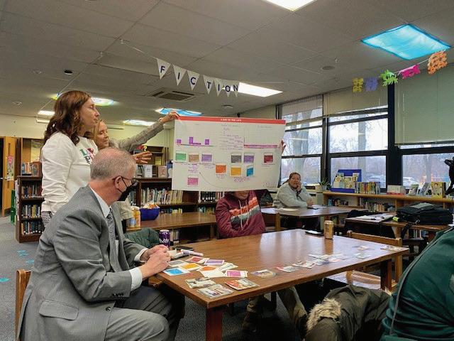
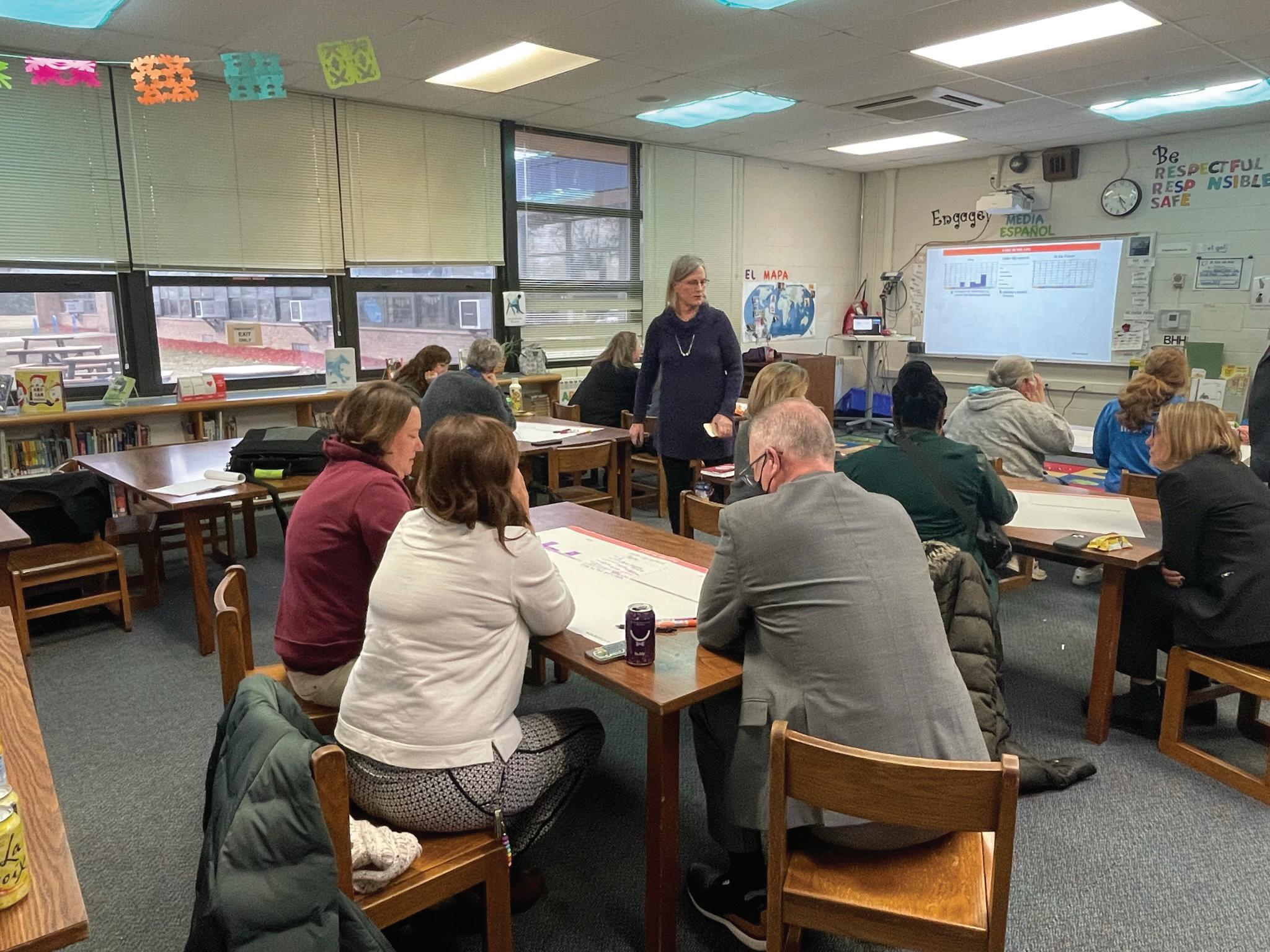
The workshop was facilitated in person on Teusday, March 7th at Dicken Elementary School. It consisted of one session with two groups: teachers and the principal, representing Educators, and staff from the Ann Arbor Public district Capital projects, representing Facilities.
The workshop was facilitated in person on Teusday, March Dicken groups: and representing Educators, and staff from the Ann Arbor Public Facilities. Participants were presented with a headline that 10 based
Participants were presented with a headline that described the project’s ideal future in 10 years based on DLR Group’s understanding of local policy and Michigan goals.
Participants went through a series of sustainabilityrelated themes and design directions to identify top goals for the project.
For each of their top goals selected, participants identified what they would see, feel, and measure if the project succeeded in implementing that goal.
Upon exiting the room, participants were asked how they might change the headlines presented to reflect the results of their VALUES charrette.
Michigan goals. of themes goals for the project. their identified what they would see, feel, and measure if the project succeeded in implementing that goal. were asked they might change the headlines presented to reflect of charrette. were asked they might change the headlines presented to reflect of charrette.
Upon exiting the room, participants were asked how they might change the headlines presented to reflect the results of their VALUES charrette.
Large group share
Connections
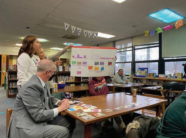
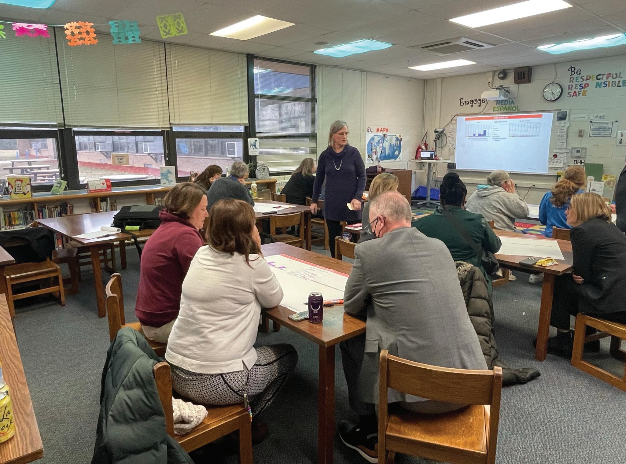
BOLD Workshop in action!
VALUES Workshop Sustainability Topics
What is sustainability
Sustainability is centered around the core idea of meeting current needs while preserving the ability of future generations to do the same.
It goes beyond ecological health and resource conservation to incorporate human health and community health; sustainability cannot be acheived without ecological, social and economic balance. The VALUES exercise is organized into twelve themes that address this holistic definition of sustainability.
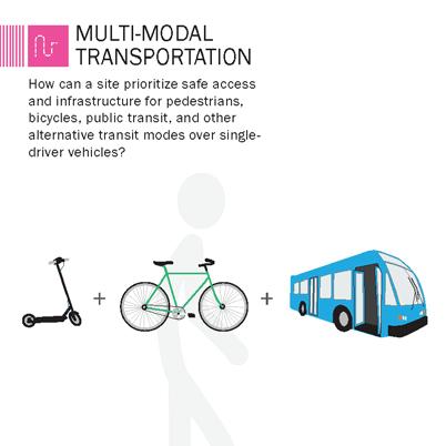
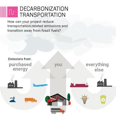
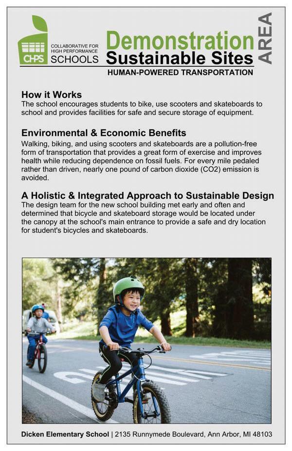
Encompasses transitoriented design, providing transportation options, decarbonizing transportation, and improving walkability and safety.
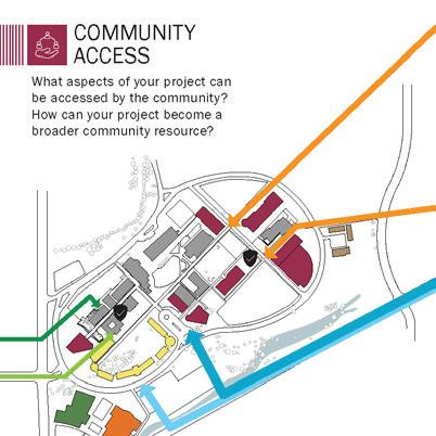
A project can ignite change in communities by providing equitable access to programs, resources, and opportunities, promoting affordability and advocating for those in need
Projects can use their outdoor spaces to restore ecology, build community, and create a strong sense of plance.
A project can support its community by providing public resources and programs, encouraging neighborhood vitality, forging partnerships, and involving the public in decision making processes.
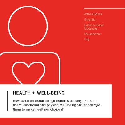
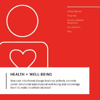
A project’s design can promote mental, physical, and emotional well-being and support users in accomplishing their personal goals.
Projects can establish practices that support safety and security, efficient operations, and responsible procurement and disposal.
A project can use design to celevrate its history and context and develop a strong sense of place that speaks to the identities of occupants and surrounding communities.
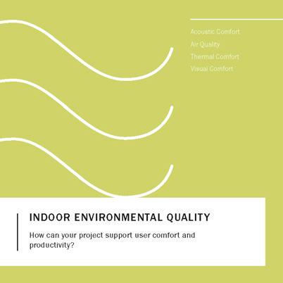
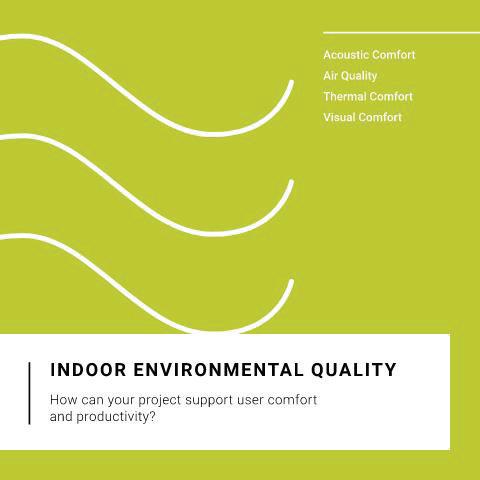
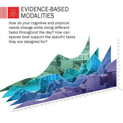
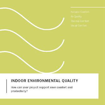
Acoustic comfort, air quality, thermal comfort, and visual comfort support occupant health and well-being, cognitive function, and performance.
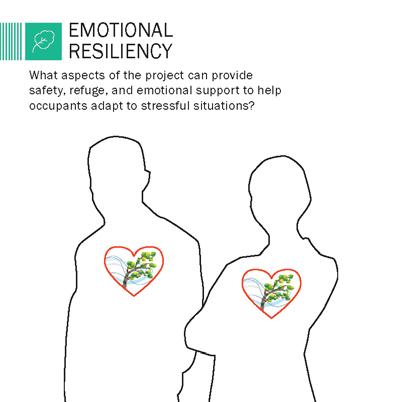
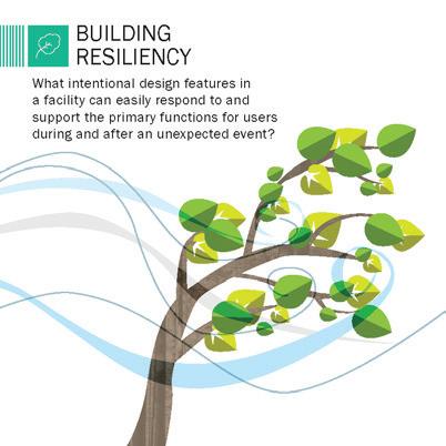
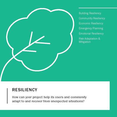
Intentional design can support the ability of buildings, sites, individuals, and communities to respond to, withstand and recover from stressful or adverse situations.
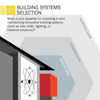
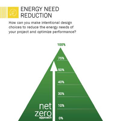
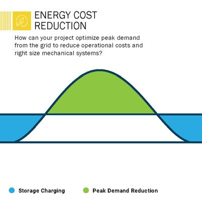
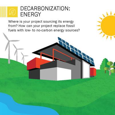
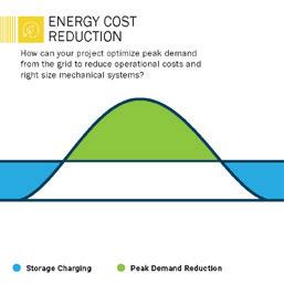
Generating renewable energy, reducing energy consumption and cost, modeling how a proposed building design will perform in the future, and intentionally selecting building systems.
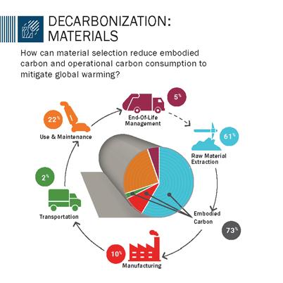
Building materials impact human well-being, carbon consumption (both embodied and operational), and cost over the course of their lifetimes.
Water encompasses water quality, water and stormwater management practices, hydrological balance, and water’s cultural context in a community.
While stakeholder groups chose different cards or interpreted cards in different ways, they often expressed similar goals and values. The following key themes arose across stakeholder groups in the workshop and can be used to guide project decisions going forward. Consensus was reached by comparing the top shared cards across these groups. Despite each groups unique expertise and difference in perspective, there were many shared cards between the two.
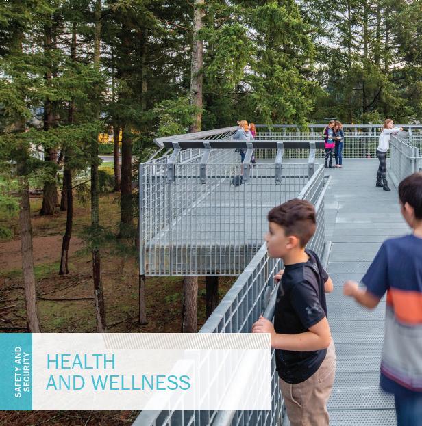
Health & Wellness
The school design and environment should contribute to overall health, well-being, and safety of students and faculty. These contributions all revolve around values of inclusion and sustainability to create a safe space to be in, emotionally and physically. Discussion emphasized mental health and bringing natural elements into the building.
Best Practices in Operations
Designimprovements should amplify and build upon the success of previous accomplishments in energy reduction and decarbonization to truly offer comprehensive education opportunities that meet community needs and provide students opportunities around future careers.
Equity & Community
The student and staff population comes from a variety of backgrounds and want to see themselves reflected in an inviting environment. Allocation of and access to resources on the campus shall lead to socioeconomic justice on campus, within the district and community. Stakeholders emphasized the importance of creating an equitable, welcoming, experience for all, as Dicken embodies the neighborhood school pride that Ann Arbor is proud of.
Top Shared VALUES
Educator Team VALUES
Capital Projects Team VALUES
BOLD Workshop Overview
What is BOLD?
The BOLD visioning Workshop is an investigation into the desired teaching and learning and the relationship with a newly built environment. School design research acknowledges that there are changes happening in teaching and learning. There is an ongoing shift fram a teacher centered model to a student-centered one. Students must encounter a variety of learning activities daily and the educator role shifts to a facilitator rather than the one who imparts knowledge. Developing educational priorities provides a clear focus on what is important as the teaching, learning, and built environment work together.
Two Activities
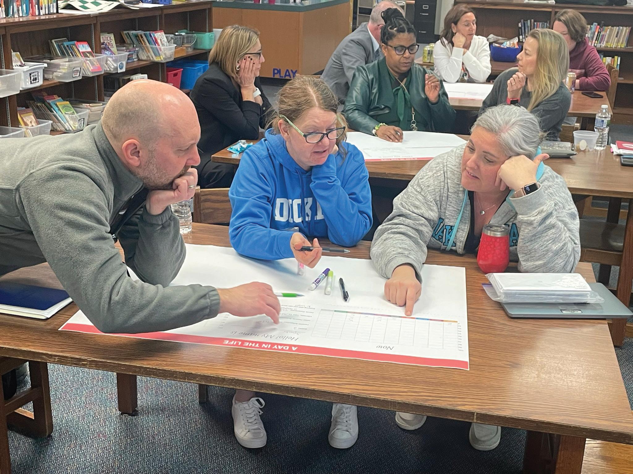
Educators and staff from the Central Office gathered after the school day for the Teaching and Learning Visioning Workshop to develop educational priorities. Participants self-selected table groups and each group chose to represent a different grade level. During the workshop, the participants engaged in two activities.
1.
Day in the Life Now and Future
After creating a student persona, each group utilized learning activity cards to describe how their student would have gone through a day of learning at their current school now. Followed by completing a bar chart for the time the students would engage in different learning activities during the day. After future-forecasting, each group redesigned the day of learning for their student in the future and completed a new bar chart for the time their student would engage in the learning activities for a day in the future. Completing the activity, each group shared their stories that represented the students day in the future and analyzed how the bar chart fiffered based on learning activites now and in the future.
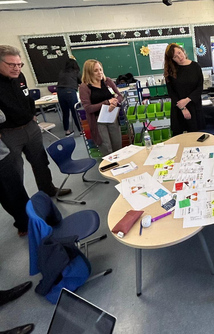
2. Learning Connections
This interactive workshop utilizes descriptive cards to explore the different elements of the learning environment, ensuring that priorities support the desired teaching and learning. To begin, a set of cards describing several types of learning were given to participants who were arranged in groups. Together, each group selected one card describing the type of learning desired within their environment in the future when space constraints were lifted. The next set of cards were provided to each group so they could select a card that descrives the teaching the best supports the learning they chose. Following, the groups then selected three cards describing the space that would best support teaching and learning selections, followed by furniture, technology, and safety.
Day in the Life Discussion
Large group share Learning Connections Share
BOLD Workshop in action!
BOLD Workshop Top Learning Connection Themes
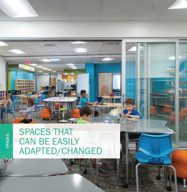
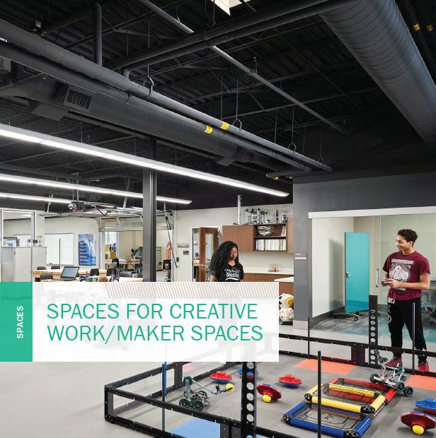
Space Matters
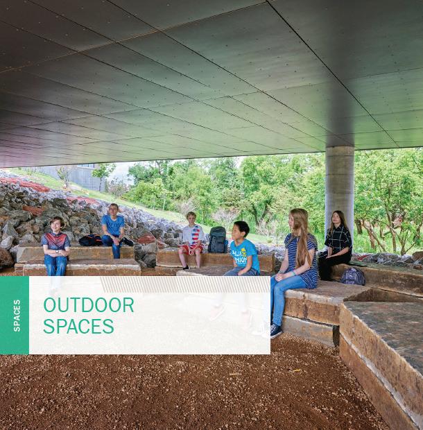
To better perfom the strategies of teaching and learning, the environment must respond. Walls that can be modified to create different configurations will support the cycle of learning in the appropriate times. This allows for the use of diverse activity settings. Spaces that are designed for movement, creation and innovation shared a common importance. Discussions confirmed the importance of spaces that naturally allow for balance and a sense of calm and bringing in a connection to nature. Ideas of easy connections for outdoor learning to extend the experiences of learning were formed with prevailing ambition.
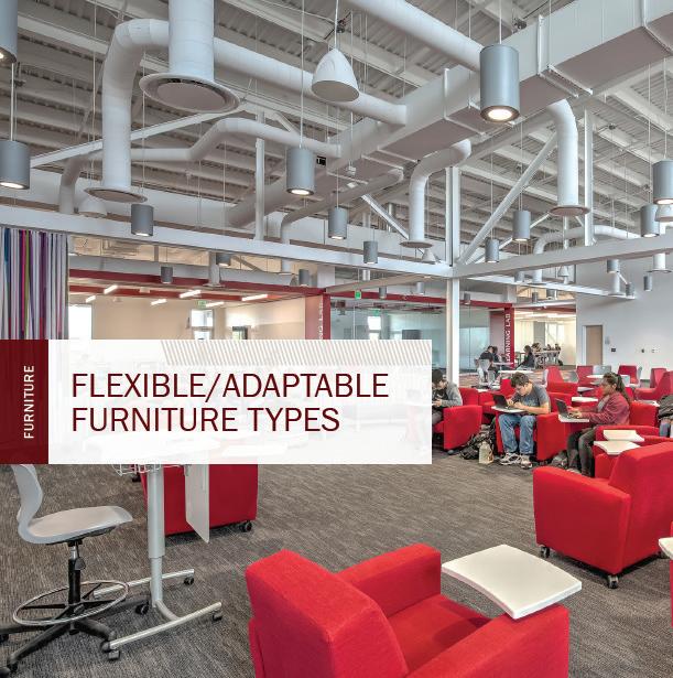
Supporting the Learning Environment
Furniture that is easily moved to and from different groupings, offers different heights, and fuels creativity is a priority. Technology that allows for greater interactivity and can be used on different surfaces was also preferred. Strategies that promote well-being and create smaller social groups within the larger school environment to foster a healthy environment and a sense of belonging are a focus. Also, the focus is to design a facility and curriculum that work together to promote sustainability and the conservation of resources.
Learner-Centered Processes
With the desired spatial affordances, students will increase their abilities to collaborate, create, and experience learning at a higher level. Through learner centered processes, students will participate in large groups, small groups, individual work with spaces to allow for presentations. Spaces that allow for movement and activity will stay engaged. An adaptable learning environment, capable of evolving and adapting with the learning practices, strengthens engagement, agency, achievement, and connectedness.
Overview
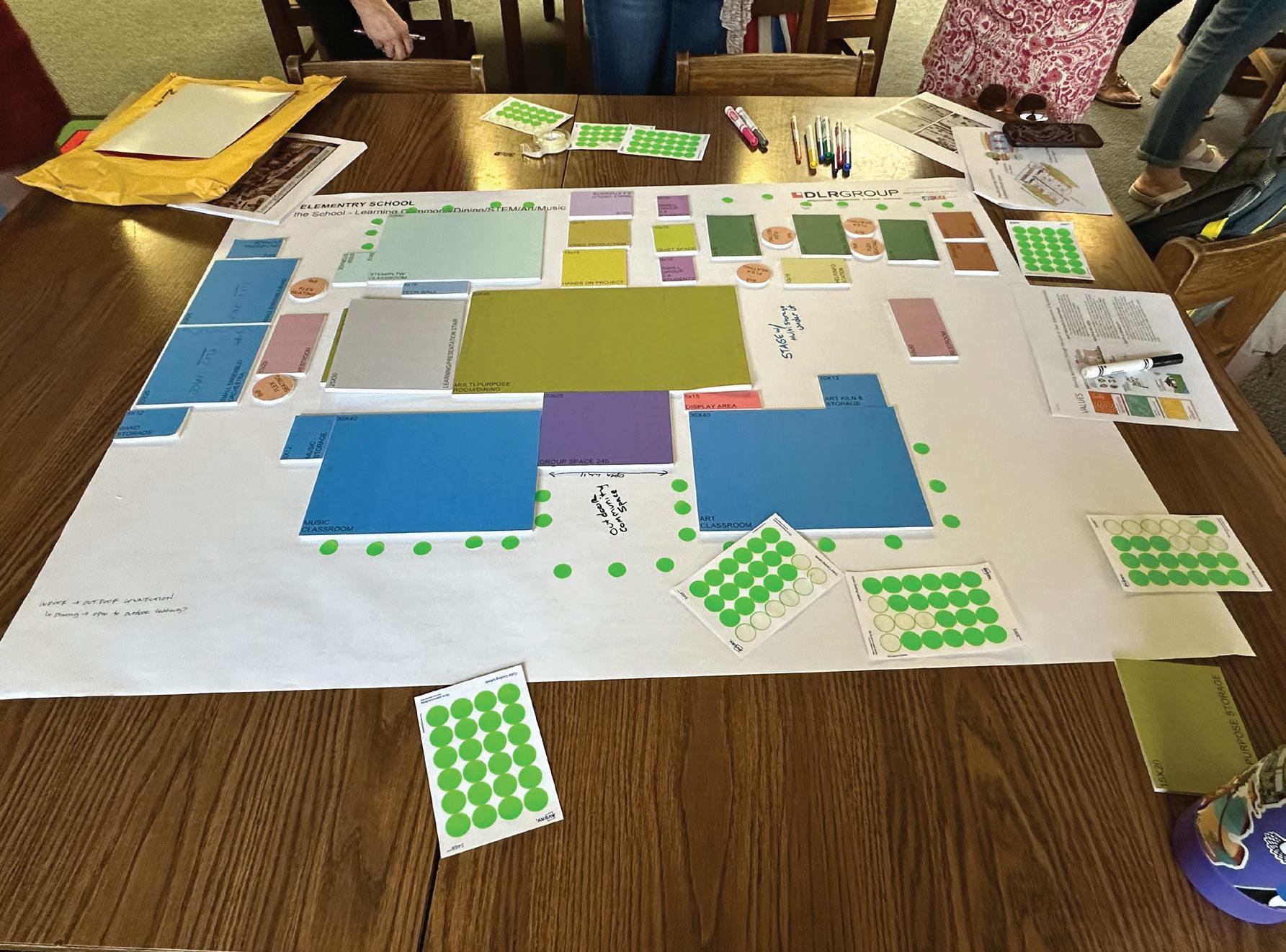
The purpose of the Curriculum/Space Alignment workshop is to bring together the outcomes from the VALUES sustainability and BOLD teaching & learning workshops and engage the teacher/staff groups to translate them into educational space needs.
Activity 1
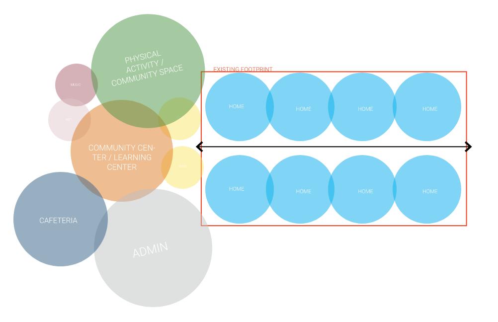
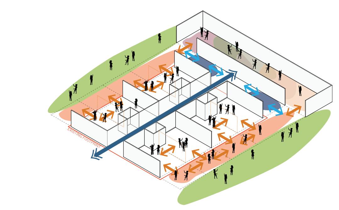
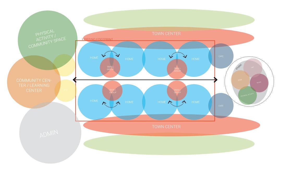
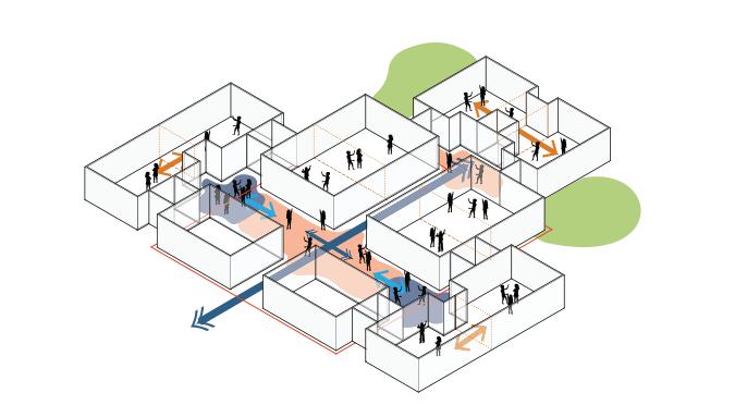
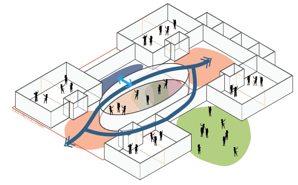
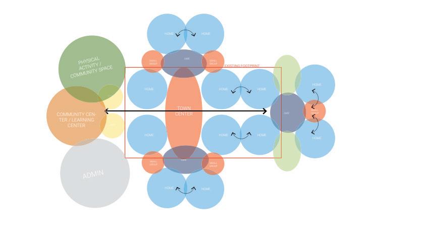
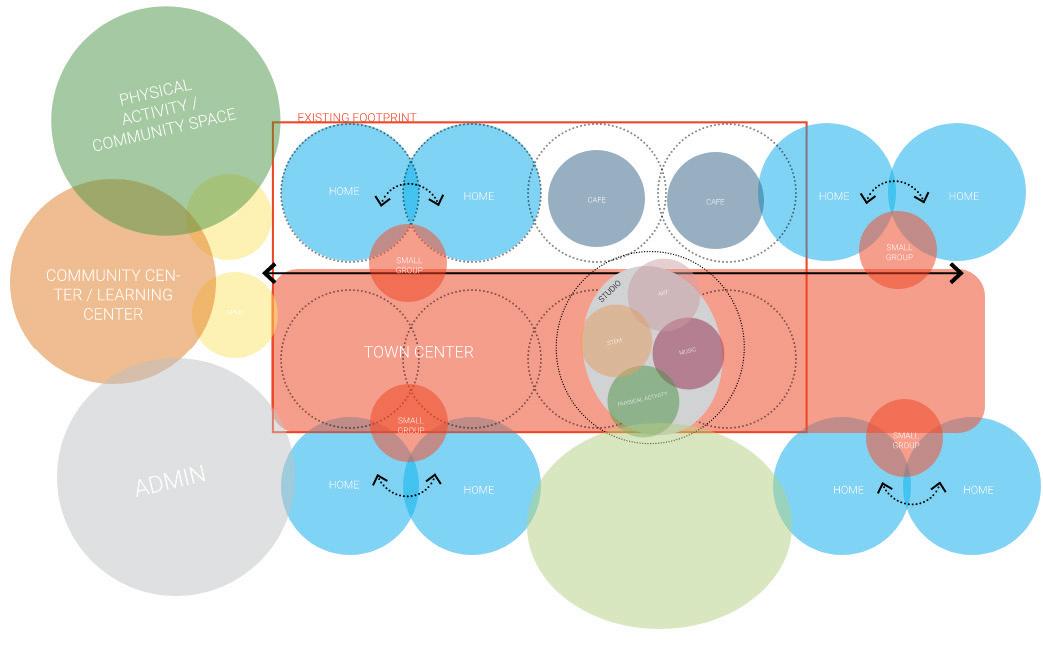
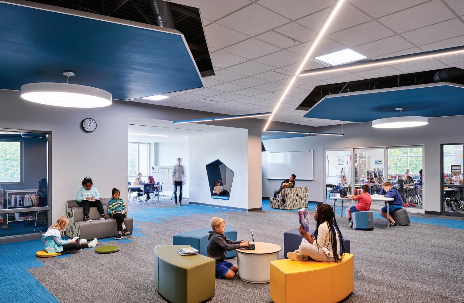
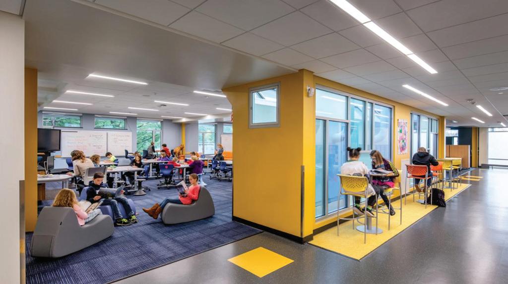
After reviewing a DLR Group presentation on the recent trends in modern learning spaces, the groups discussed the merit of these space trends for the new Dicken Elementary School. The groups spent time together reviewing diagrams for potential layouts and adjacencies of Flexible Learning Environments to a Learning Commons, multi-purpose spaces and administration areas. Flexible Learning Environments were explored to incorporate classroom areas, a shared flexible space outside the classrooms, various-sized group areas for students and support and teacher workspace.
Activity 2
The groups worked collaboratively to arrange foam blocks to describe their optimal teaching and learning space adjacencies for the future new school building.
Each group focused on separate areas of the proposed new school:
Site/Wellness & Fitness - Indoor and Outdoor
Flexible Learning Environment for Grades K-2
Flexible Learning Environment for Grades 3-5
Heart of the School Spaces– Library Media Center, Specials and Dining
Each group presented their layouts, discussed and arrived at consensus on adjacencies represented with the blocks.
Day in the Life Discussion
Large group share
Learning Connections Share
BOLD Workshop in action!
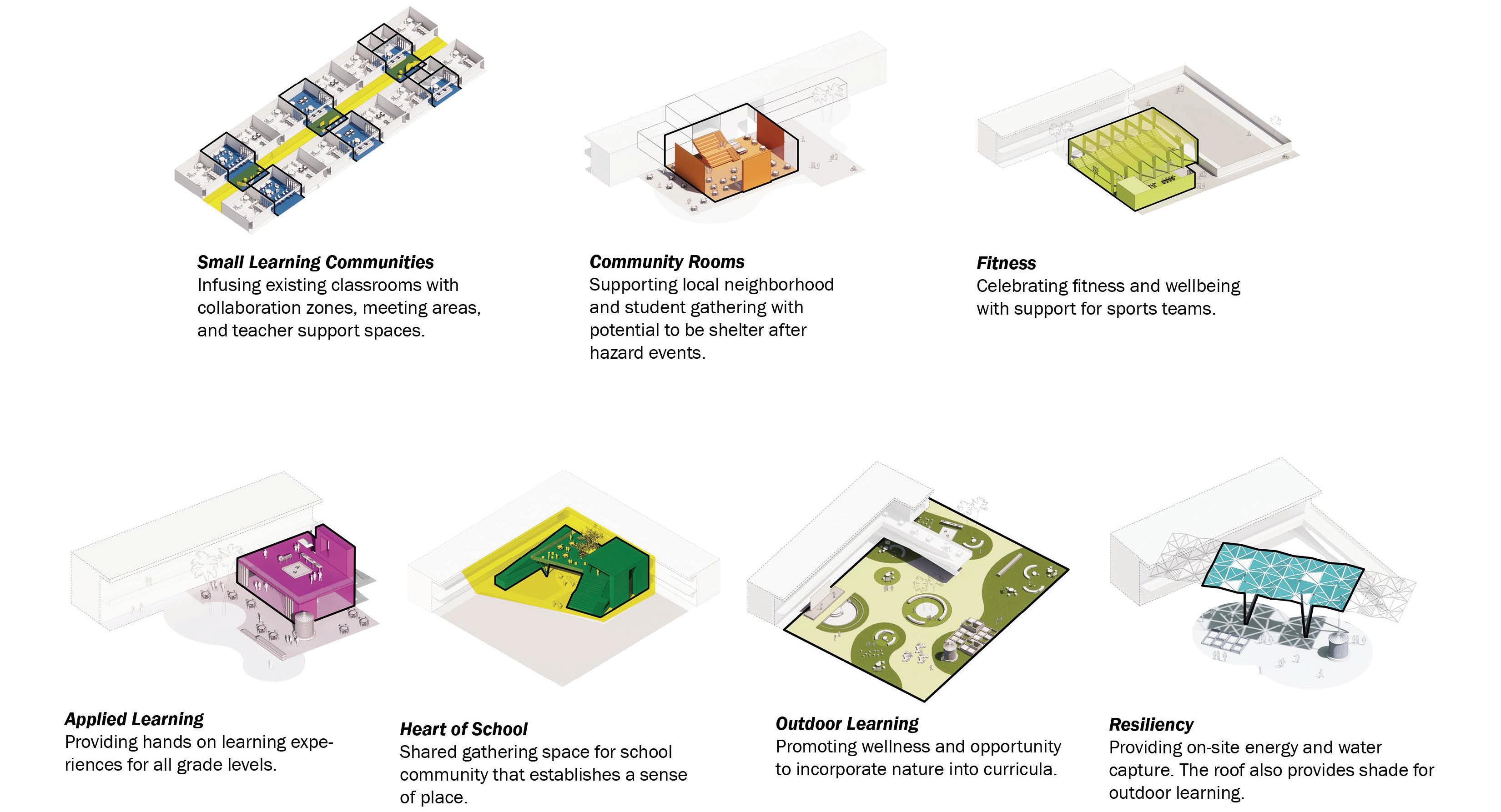
CURRICULUM/SPACE Workshop Programing “Kit
Infusing existing classrooms with collaboration zones, meeting areas, and teacher support spaces.
Supporting local neighborhood and student gathering with potential to be shelter after hazard events.
Celebrating fitness and wellbeing with support for sports teams
Providing hands on learning experiences for all grade levels.
Shared gathering space for school community that establishes a sense of place.
Promoting wellness and opportunity to incorporate nature into curricula.
Providing on-site energy and water capture. The roof also provides shade for outdoor learning.
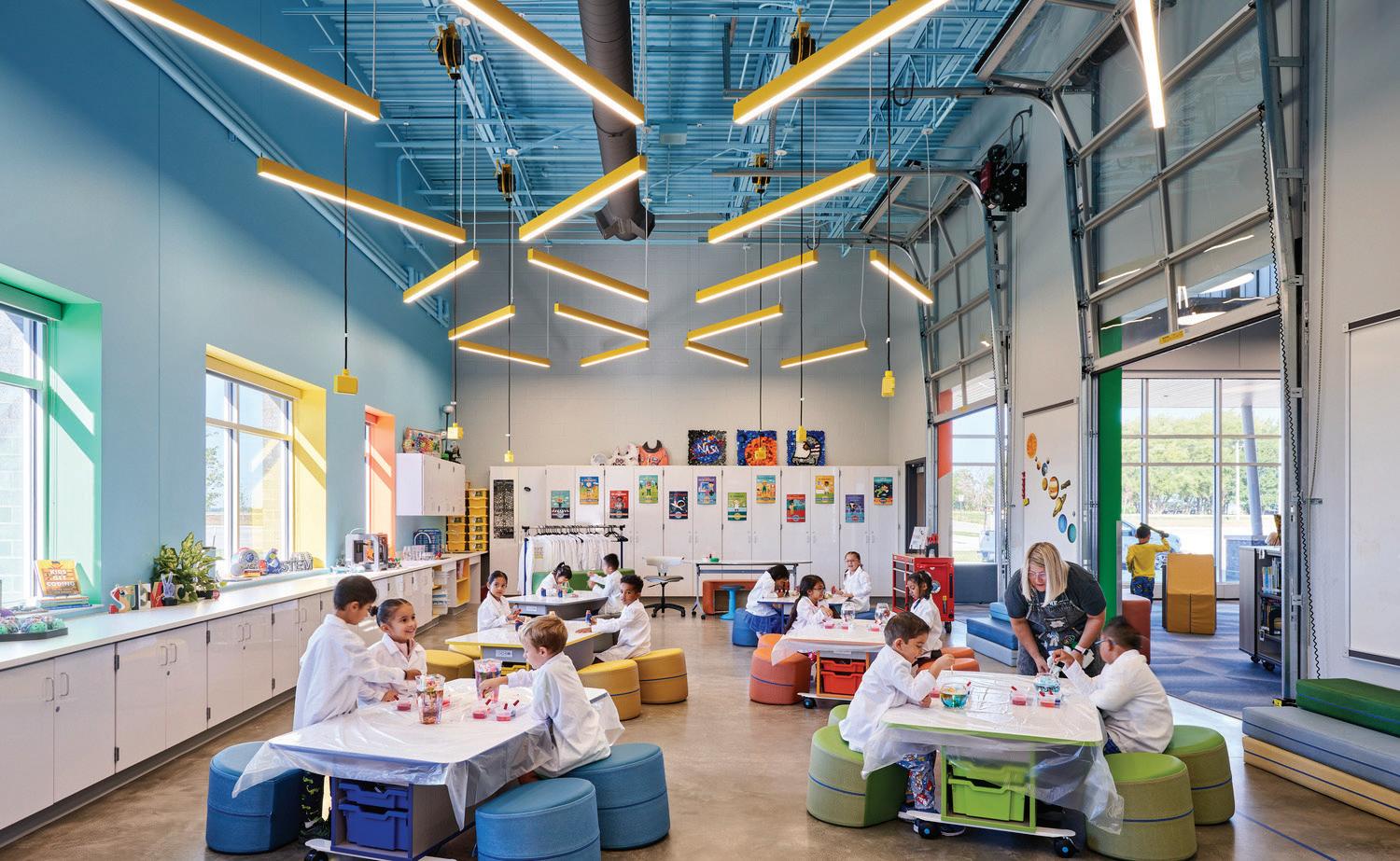
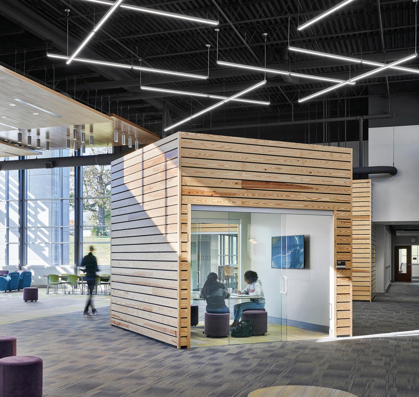
Programing “Kit of Parts” - Emerging Design Trends
OutdoorLearning
CURRICULUM/SPACE Workshop Programing “Kit of Parts” - Emerging Design Trends
Glass Garage Door
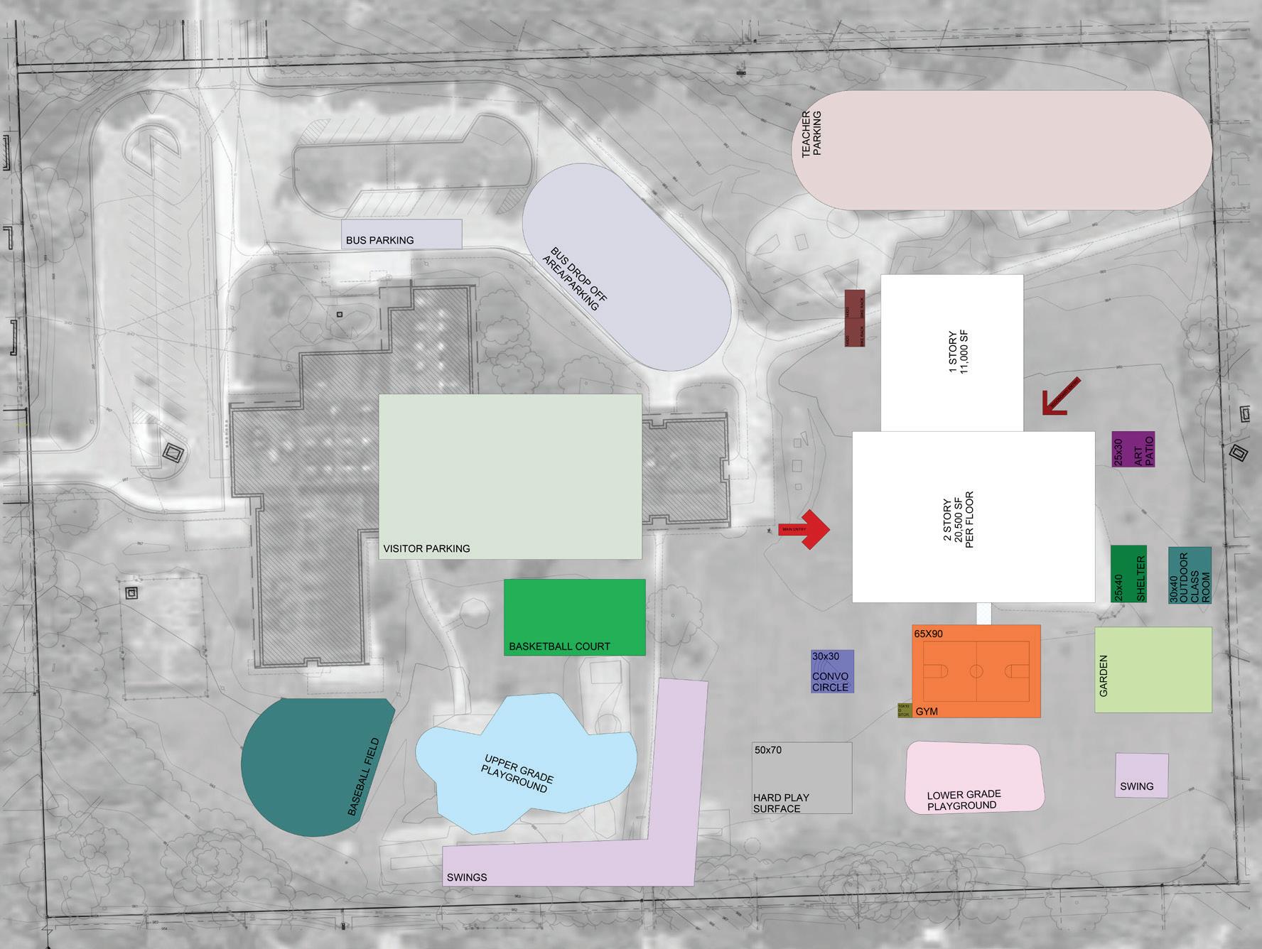
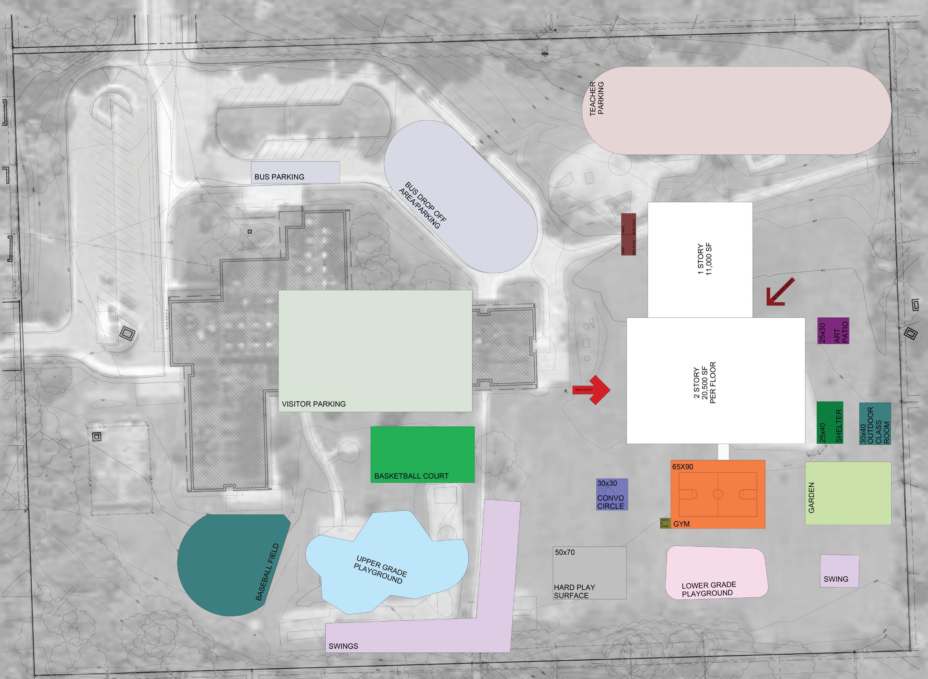
CURRICULUM/SPACE Workshop Site Programing
Parking. Vehicle & Pedestrian Circulation
Separate parking away from play area so students do not have to cross them to get to play ground.
Outdoor Gathering Area Gym Space
Provide reading/presentation circle
Have other rock or natural seating for small groups.
One Wall should be an outside wall to have windows for natural daylight.
Locate Gym near sports fields for easy access
Use Gym for Community Events
Provide adequate ventilation
Private direct access to the outdoors
Art Patio & Garden Area Plat Areas
Locate Pation with direct access to Art room
Provide a storage shed for garden area
Locate away from classroom windows to minimize distractions and noise.
One area for Upper grades and one area for lower grade
Walking Path & Marsh Setting/Pond
Provide trail around site for student/staff fitness and stress relief. Neighborhood amenity when school is not in session
Potentially create learning area around natural, low wet area of site that could be Dicken Pond.
Classrooms & Out Door Classrooms
Located to have easy access to play areas
Good views of landscape
Provide outdoor classroom area with flexible seating
Consider covered structure for rain and sunscreen
Basketball & Game Area
Provide sport surface for basketball and other hard surface games
Private direct access to the outdoors.
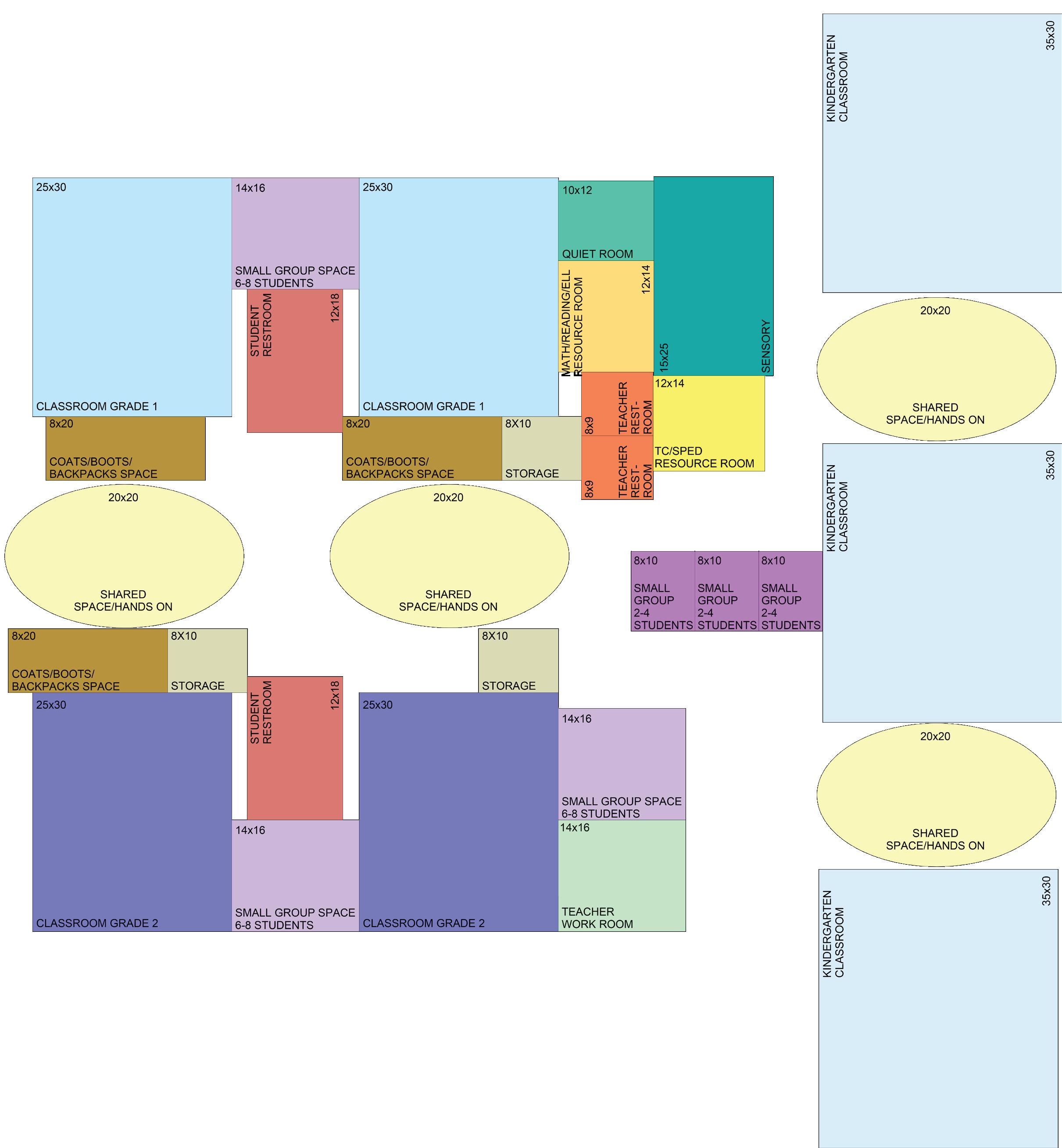
Student Support Grade K-2 CURRICULUM/SPACE Workshop
Add classroo(s) for early 5 year olds that are same size as kindergarten rooms
Pair each grade level classrooms together and provide shared resource and small group collaboration rooms between them.
Locate small collaborative group rooms near classrooms to be multi-use for various students uses
Student support services should use the small group collaborative space between classrooms and perhaps have another small group space in the learning community area. Currently due to lack of space, students are sent to separate are of the building and this is disruptive. Students loose instructional time with the transition distance and it may create a negative stigma to be moved awat from peers.
Sensory/well-being space near/inside the Learning Community.
Student support service staff nees a work space and shared conderence room somewhere in the building
Provide coats/boots storage areas inside the kindergarten and early 5 rooms
Provide coat/boot storage area for grades 1-5 outside of classrooms
Locate restrooms inside the kindergarten and early 5’s Locate restrooms for grades 1 &2 between or near classrooms but not inside.
Provide staff restroom nearby.
Create central shared space that all grades can access Arrange classrooms around central area
Storage for activities within this space
Provide direct access to outdoors from kindergarten rooms and early 5 year old rooms for sure and potentially for other grade level rooms to share.
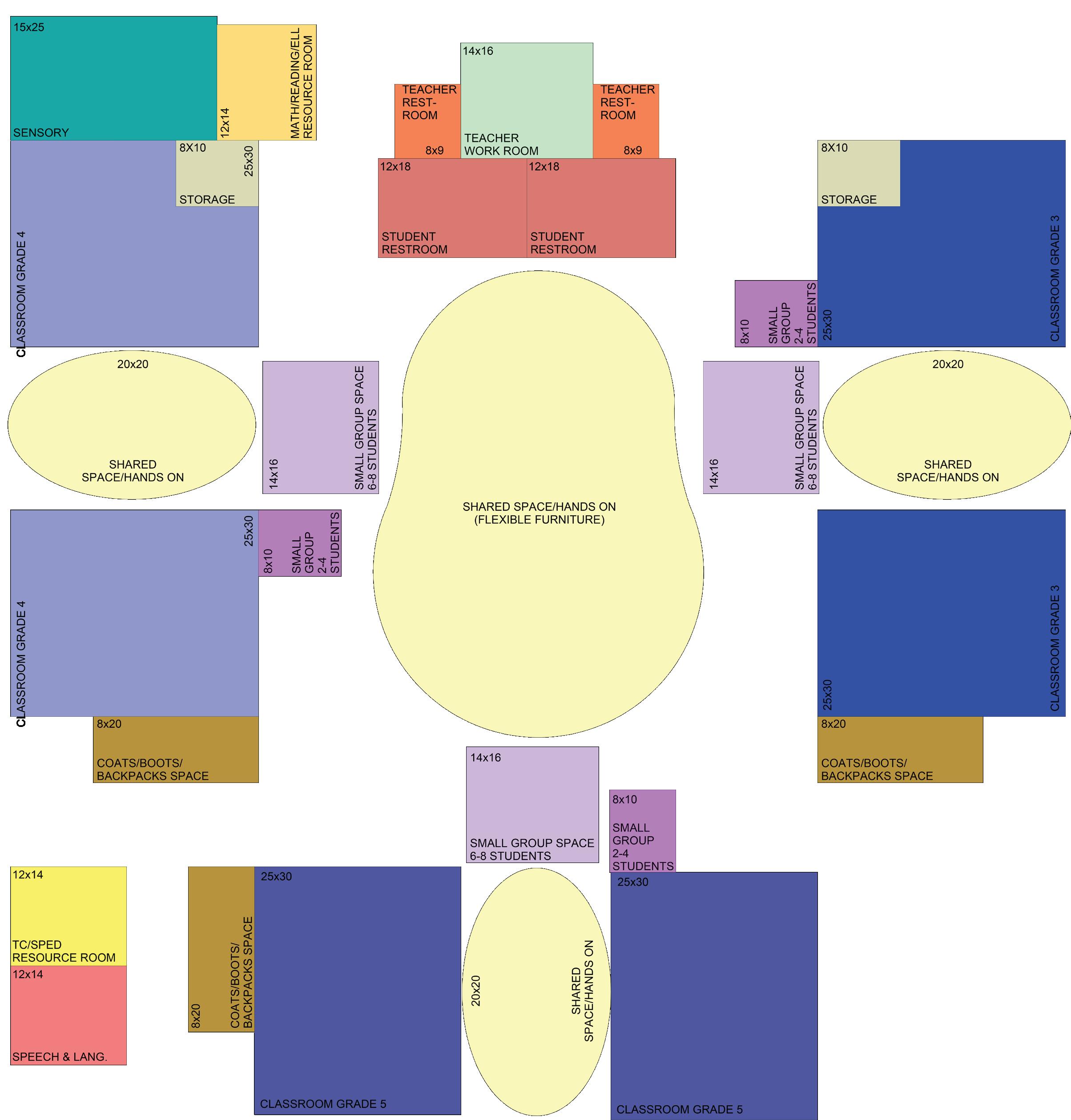
CURRICULUM/SPACE Workshop Student Support Grade 3-5
Classrooms & ELL Classrooms Small group collaboration space
Pair each grade level classrooms together and provide flexible shared space between the classrooms to expand either classroom or connect the two classrooms
Provide glass operable wall or doors
Provide upper level ELL room
Locate small collaborative group rooms near classrooms to be multi-use for various student uses.
Provide coat/boot storage areas for grades 3-5 outside the classrooms
Locate restrrooms at one end of the open space inside the Learning Community
Provide staff restroom nearby
Assuming this 3-5 Learning Community is on the second floor above the k-2 Learning community, provide a shared outdoor patio classroom area.
Student Support Space
Sensory/Well-Being space near/inside the learning community
Speech & Language resource space
Student support service staff needs a workspace and shared conference room somewhere in the building
Central Shared Space
Create central shared space that all grades in this learning community can easily access.
Arrange classrooms around the central area
Provide glass garage door between classrooms and central shared space
Provide daylight/window area that reaches the central area
Staff work room to be shared.
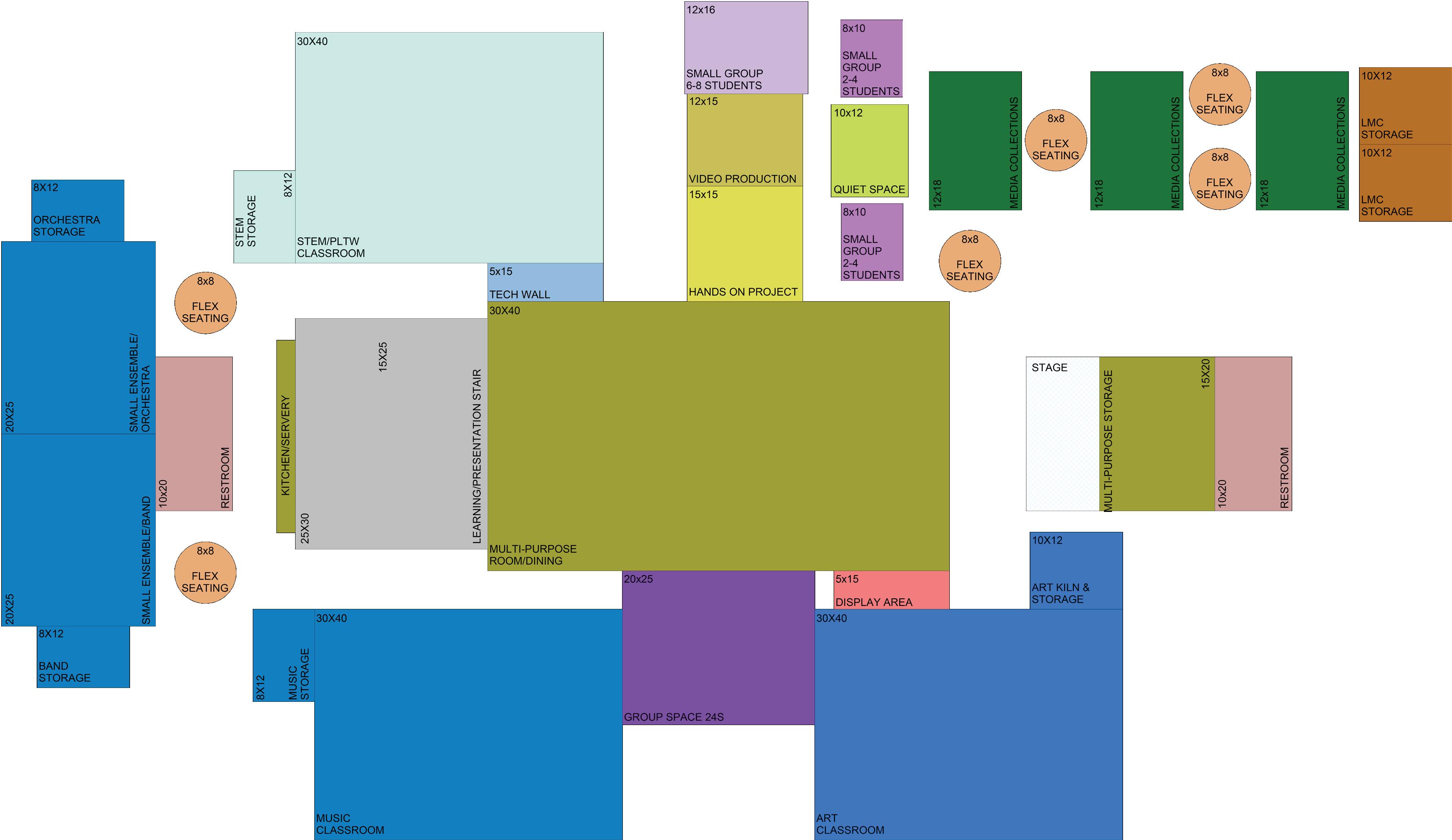
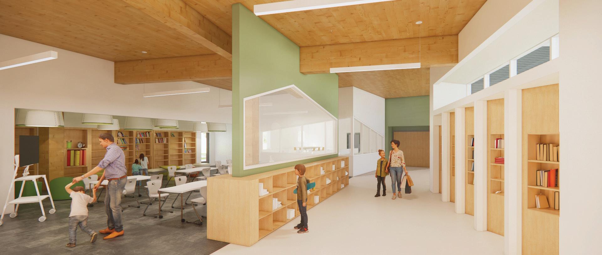
Heart of the School | Learning Commons
Central Area for Dining, Performance & Commons
Library, Commons, Dining and performance areas to be linked to provide flexibility for larger events. Book and media collections should be tucked to the side. Provide learning/presentation seating in the space Learning commons should be open and on-display. Book collection could be split with some older grade level materials on second floor.
Variety of small group and individual seating spaces. Provide storage under stage.
Media/Video/Broadcast/Green Screen and Hands on Maker space near commons.
PLTW | Stem Classroom
When PLTW becomes a full program, provide a dedicated room to avoid carting materials around to all classrooms.
Art Classroom
Natural daylight is important
Provide glass display case to show student work outside art room and all around the central dining/performance area.
Provide access to outdoor patio
Music | Orchestra | Band & Flex Space
Provide Dedicated Music Classroom
Provide two flex spaces with instrument storage and/or Orchestra and band rooms
Restrooms
Provide adequate restrooms for larger group and community activities in center space
Consider two separate banks of restrooms (1) near kitchen/server area and on other end behind stage.
Outdoors
Link dining/performance space to outdoor patio area. this can be an opportunity for community use. Outdoor access from Art and PLTW to outdoor patio space.
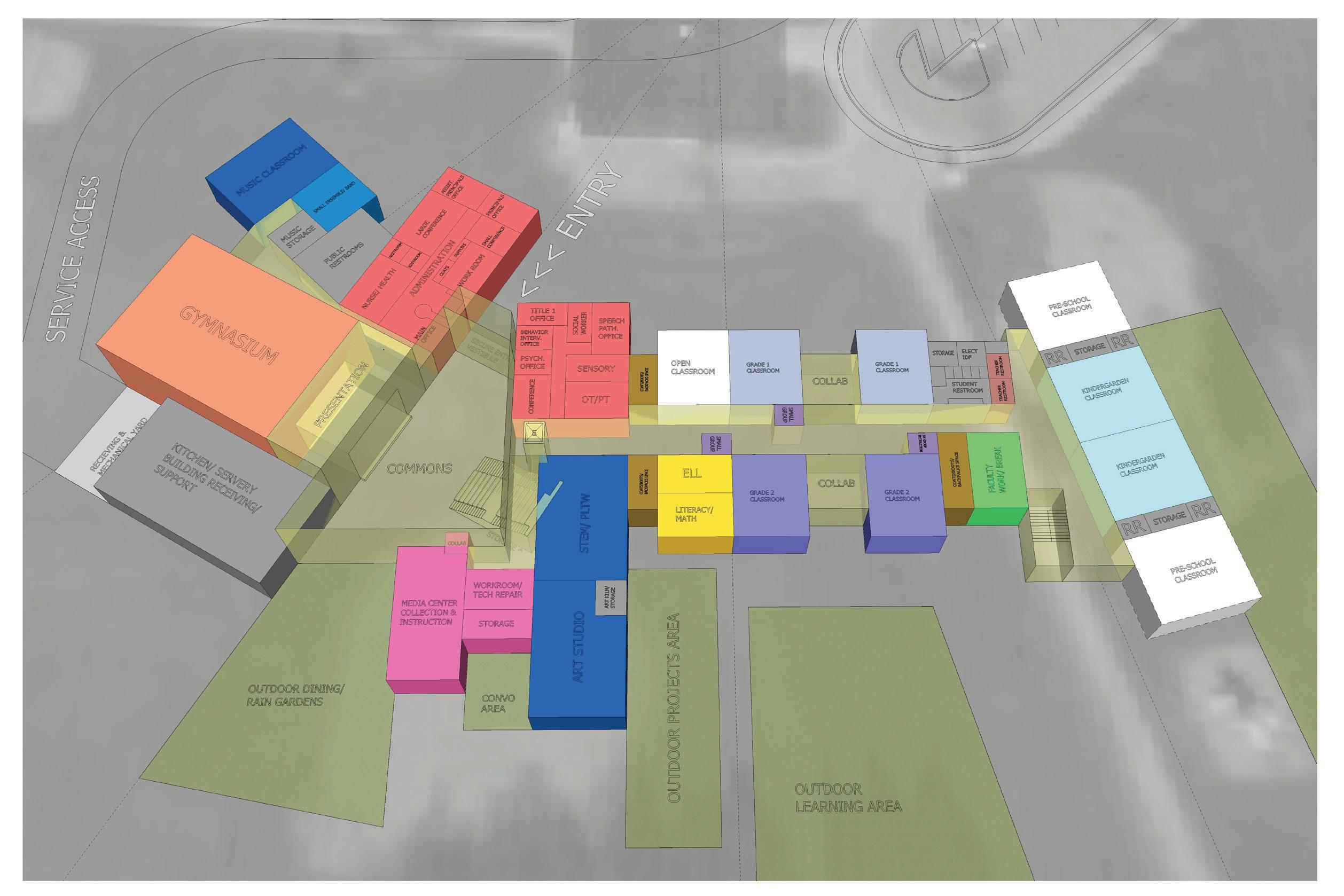
CONCEPT Workshop Overview
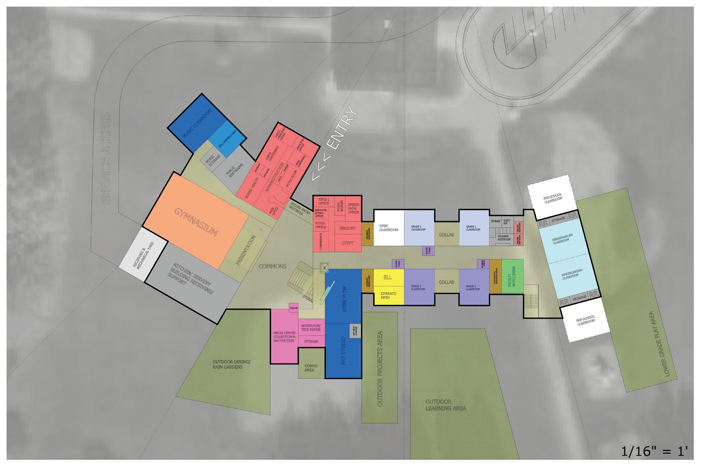
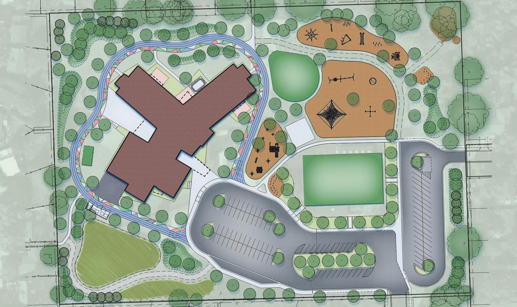
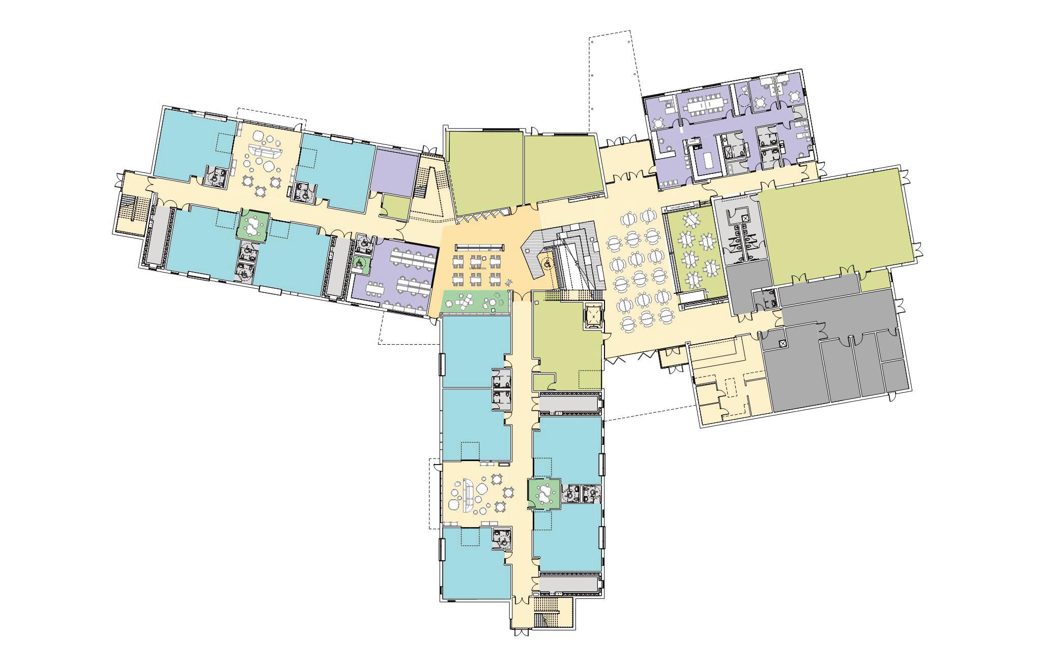
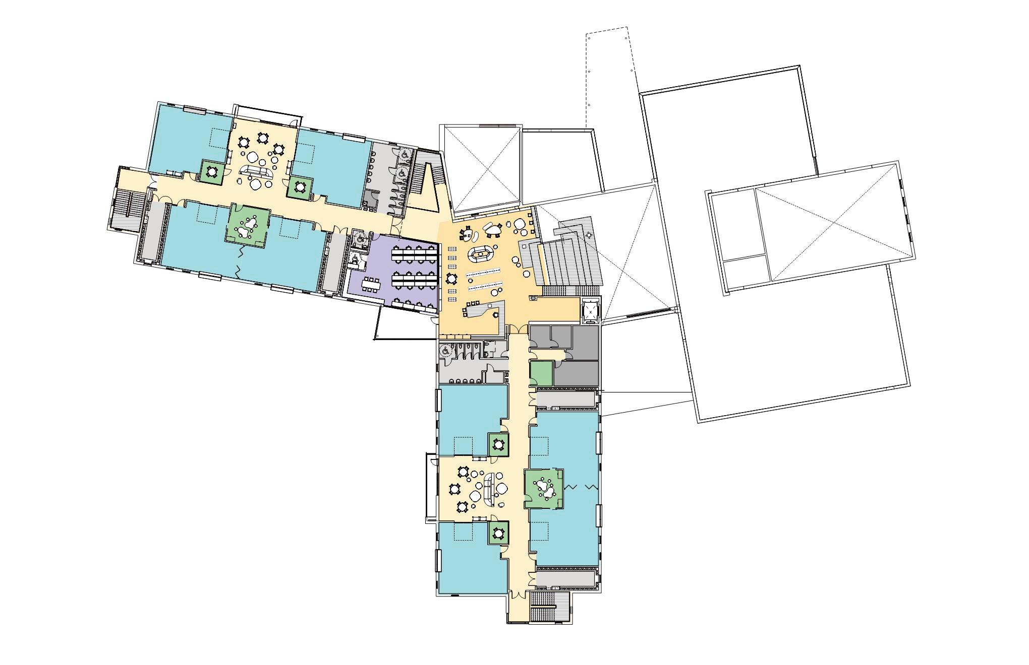
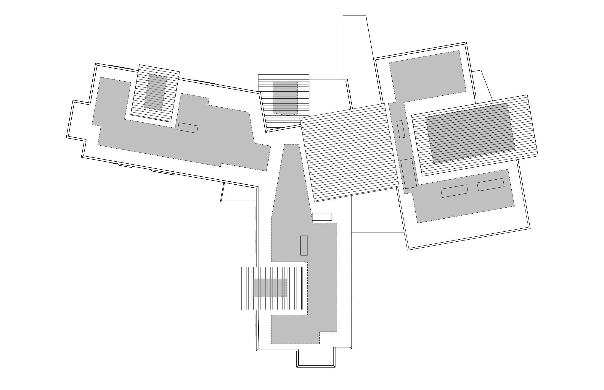
LEVEL 02 - CONCEPT PLAN
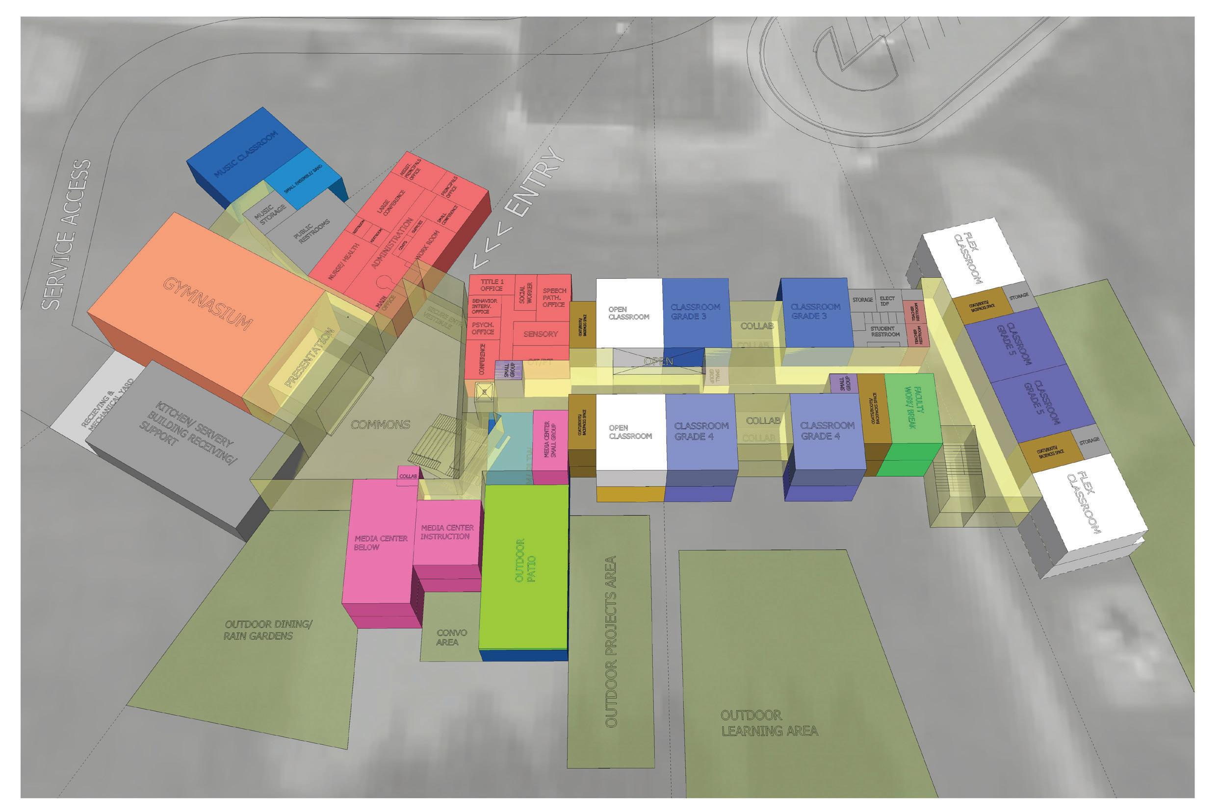
LEVEL 02 - CONCEPT MASSING
This workshop formed the basis for the final concept shown in Section 3 Concept & Site Concept. During this workshop the design team shared floor plans and initial massing with the Dicken Community.
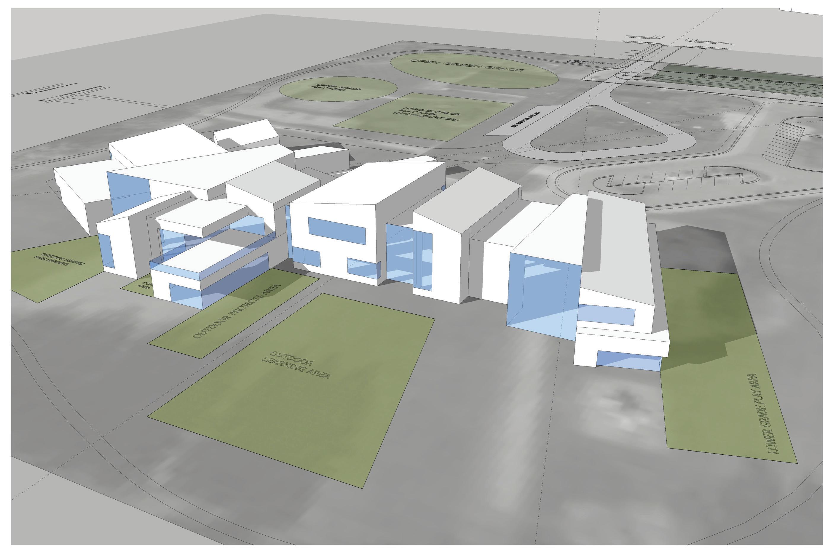
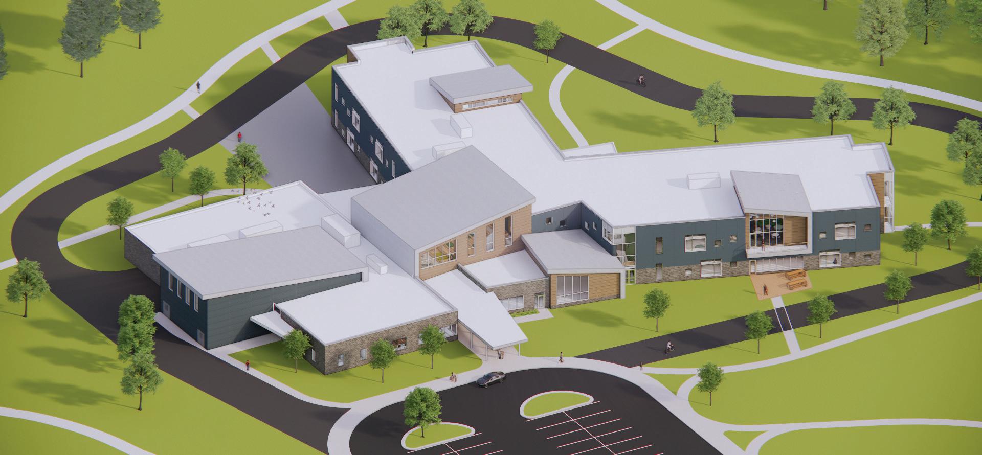
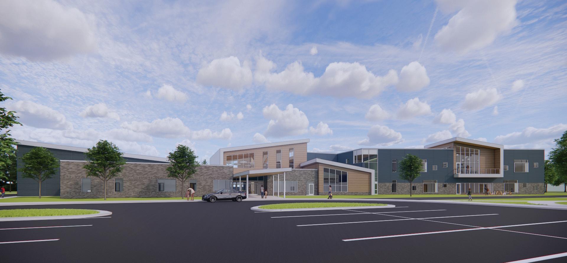
CONCEPT MASSING - VIEW LOOKING NW
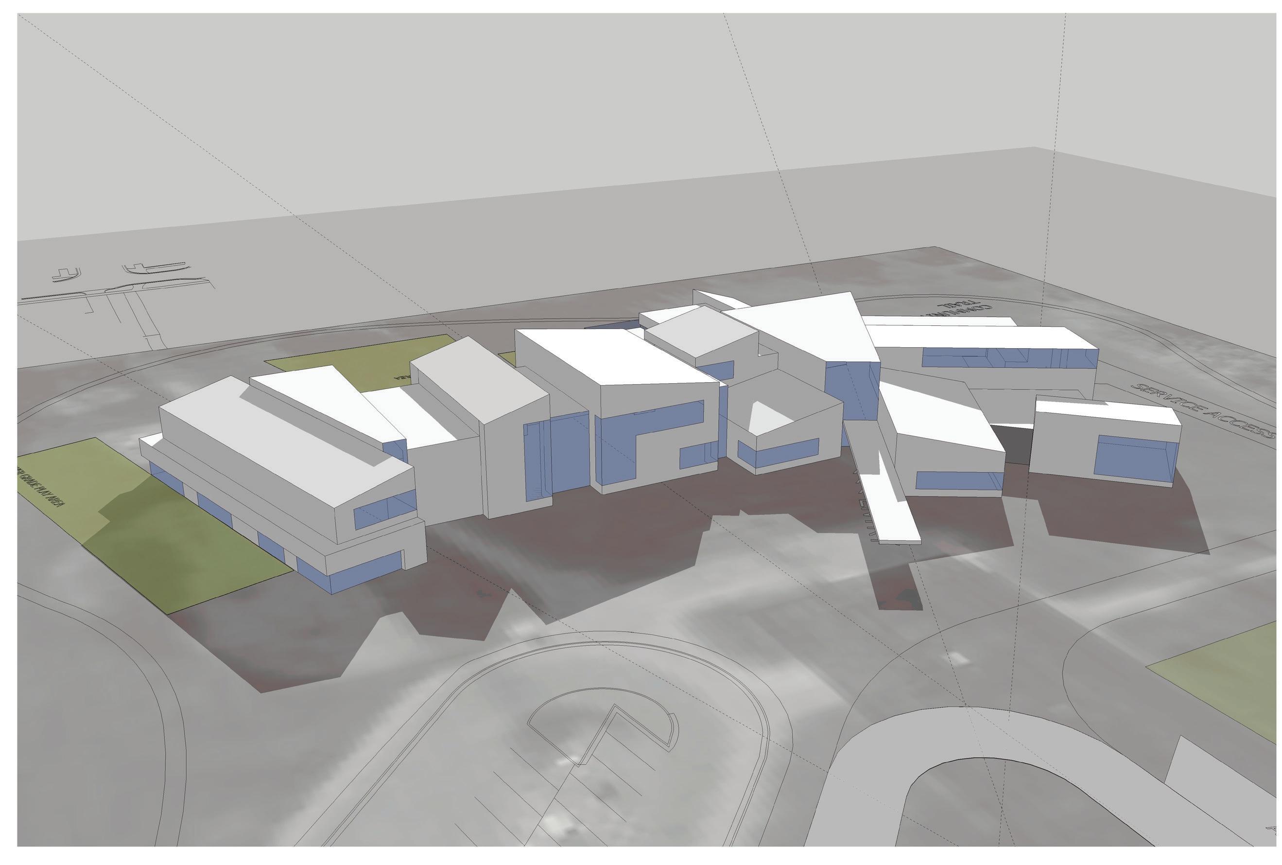
CONCEPT MASSING - VIEW LOOKING SW
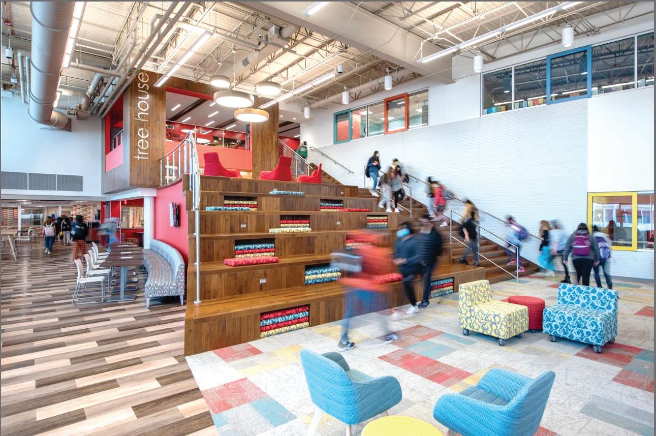
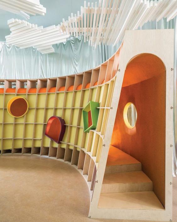
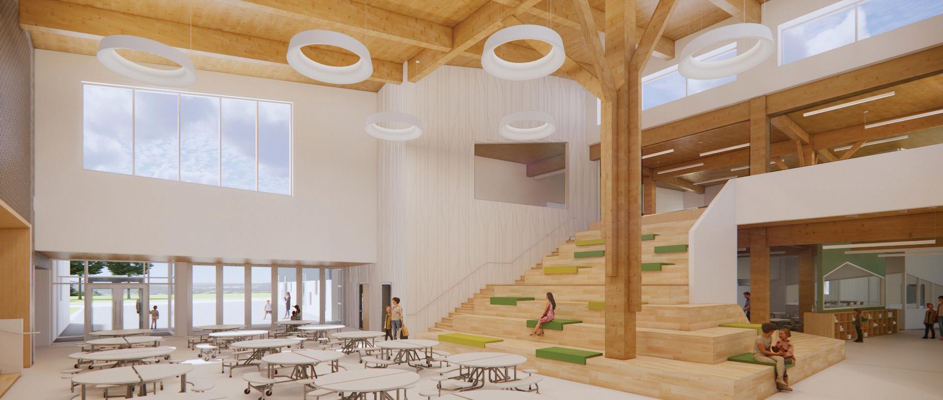
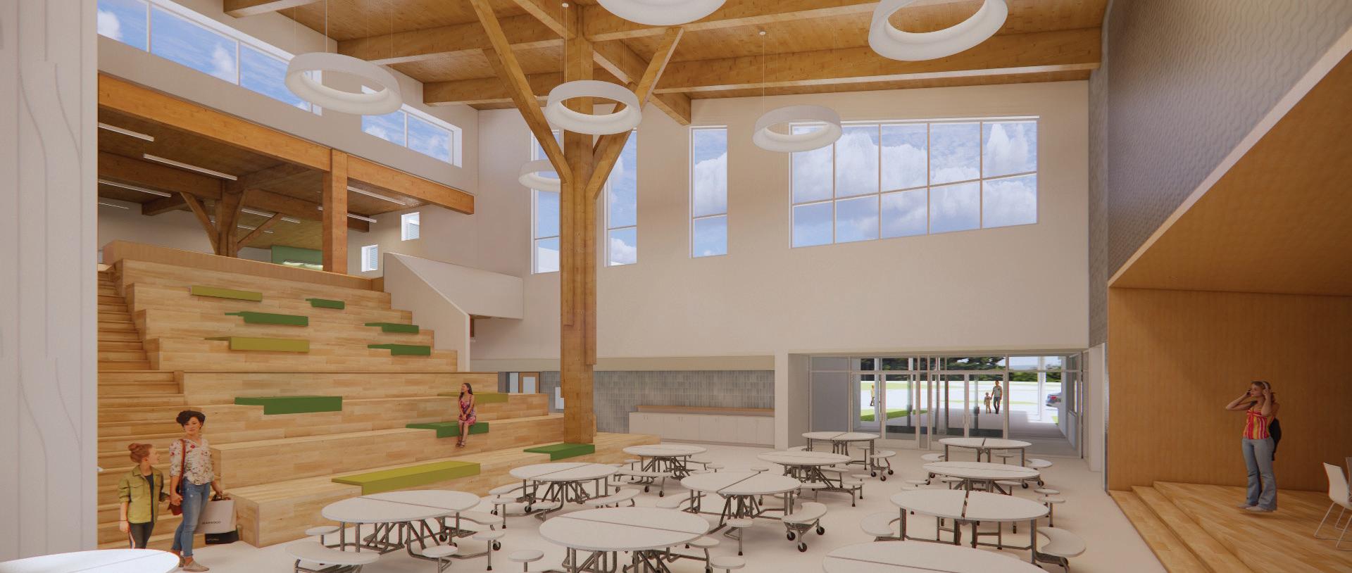
Concept - Tree House
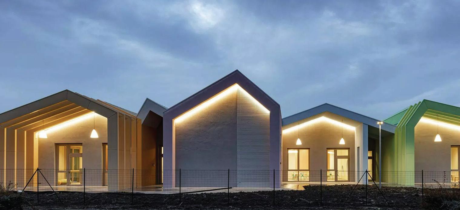
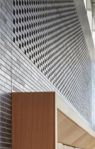
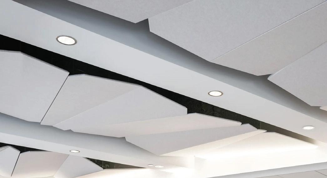
The new Dicken Elementary school will be designed around the idea of a tree house and encouraging exploration. Biophilia will play a large role in the selection of materials and sculpturing the connective tissue throughout the building. Tactile elements will be incorporated thoughout the collaborative and circulation pathways to encourage students to engage their senses. Branch and leaf patterns will be used at various scales to symbolize the sense of surrounding shelter of the tree. Linear patterns of light and shadow will also contribute to a dynamic environment, symbolizing how rays of sunlight radiate through a forest. Pops of color will be used thoughtfully to create different zones and support wayfinding.
• Embrace natural materials & textures
• Emphasize community and collaborative areas with pitched ceiling planes
• Angular geometry and patterns woven through floor plans and design gestures
• Create sense of exploration and play
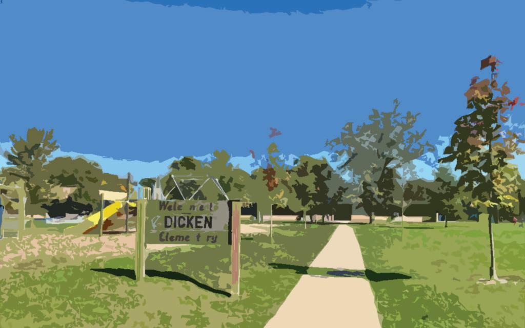
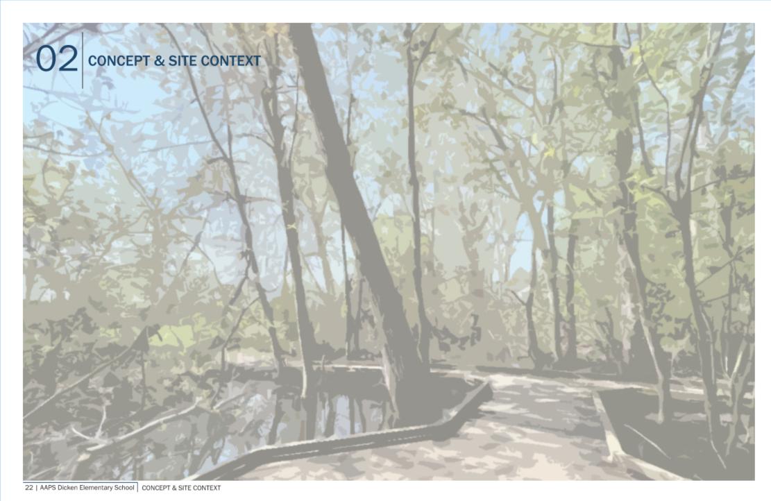
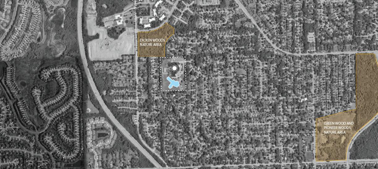
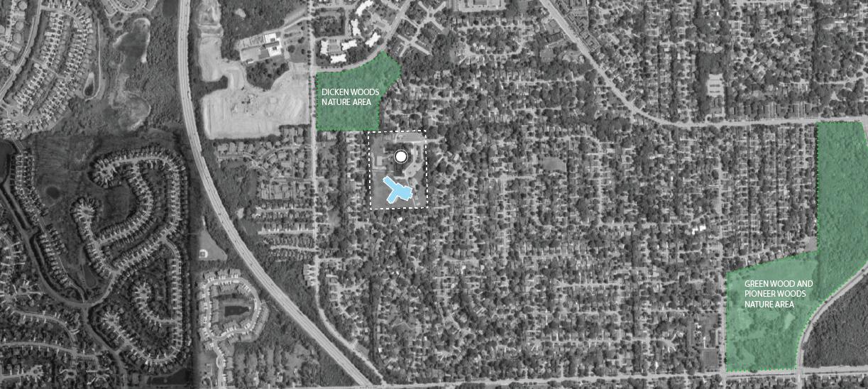
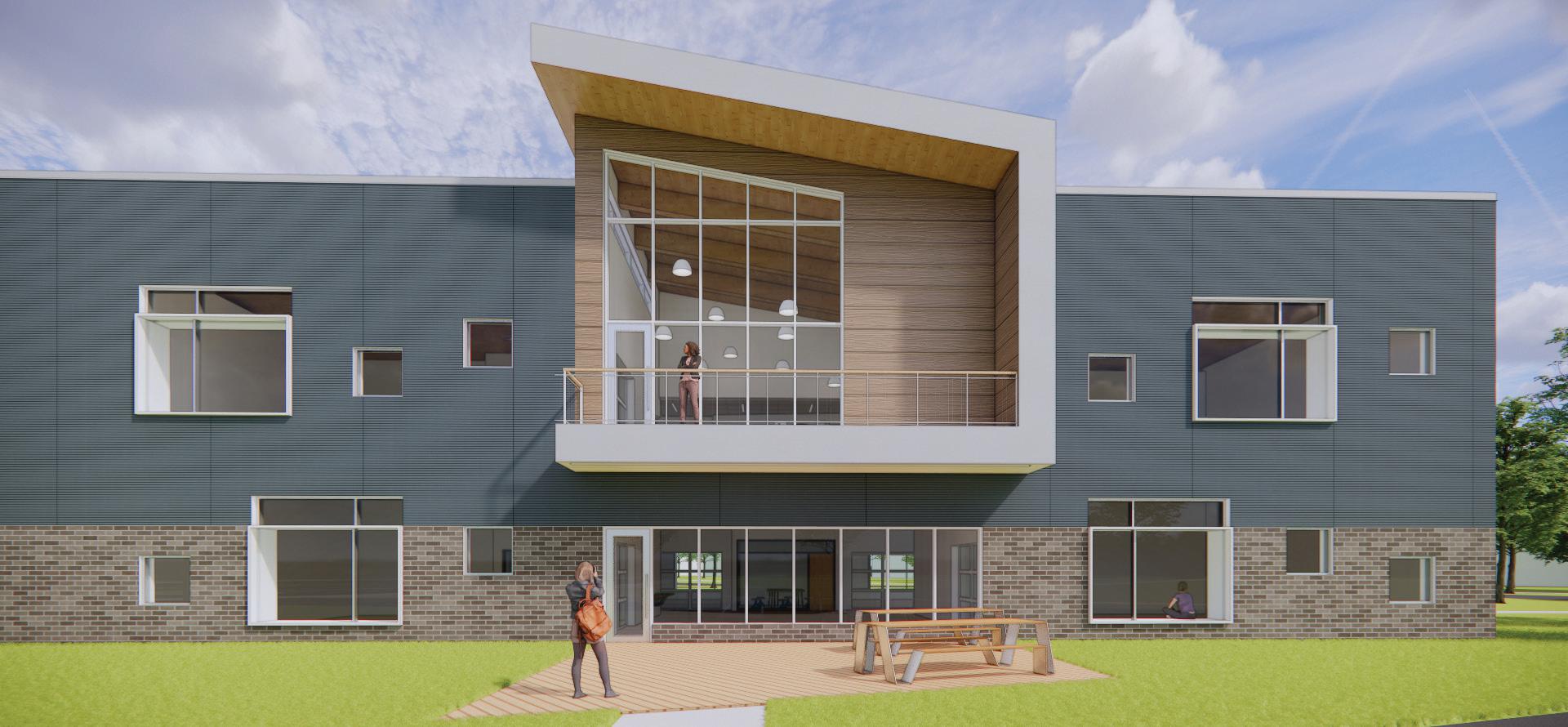
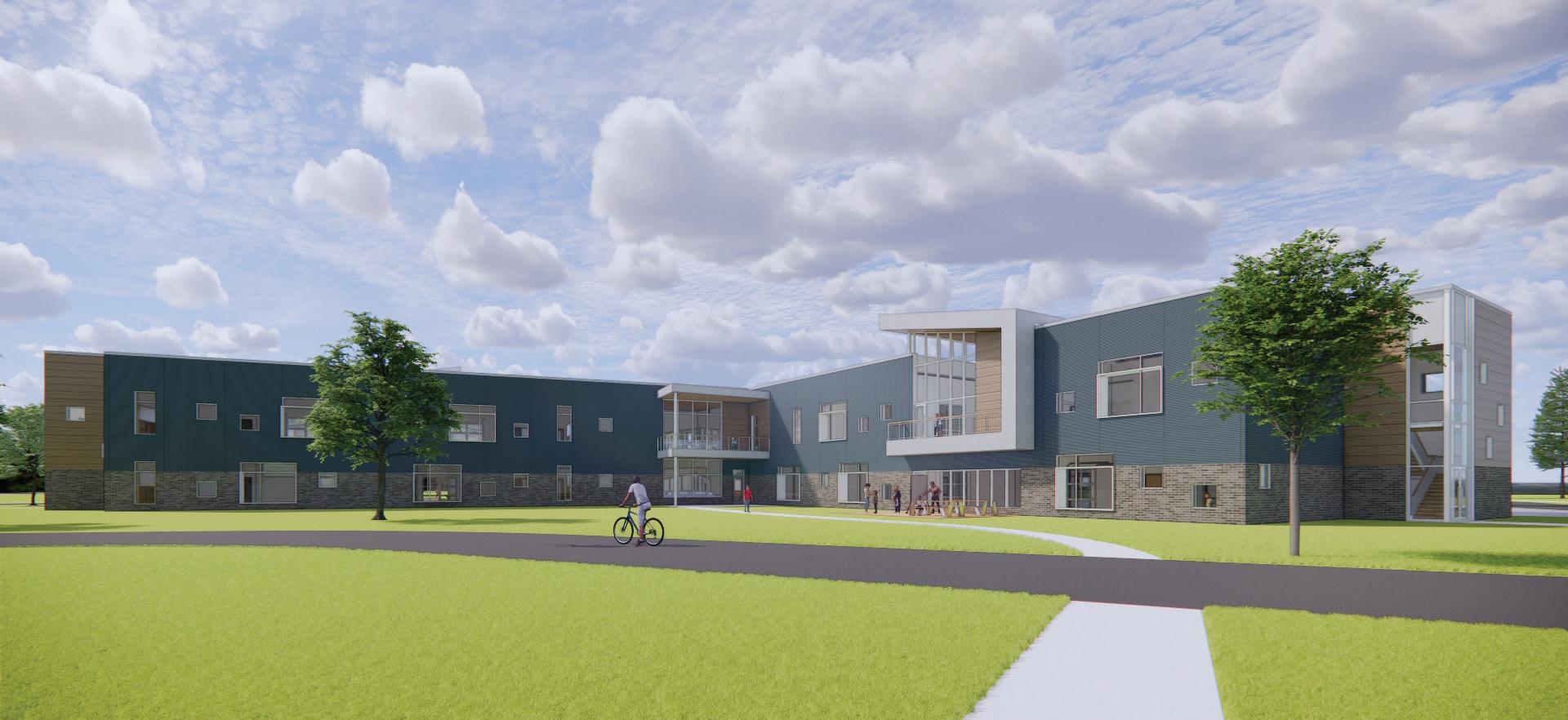
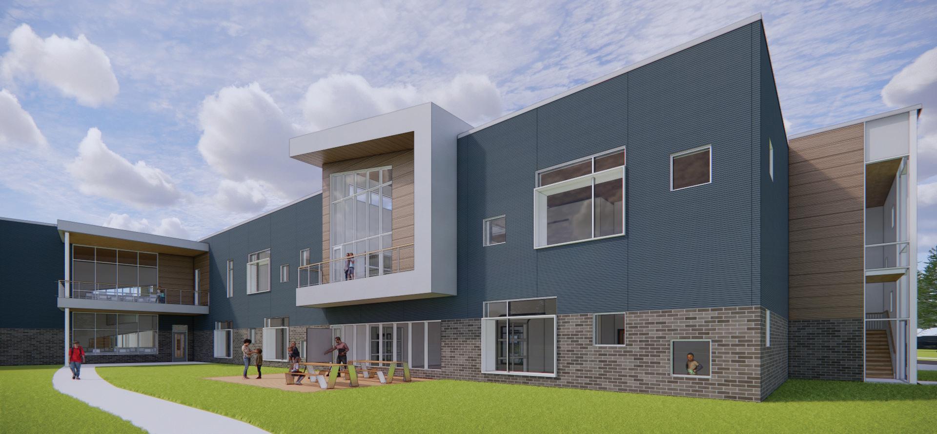
The Dicken Elementary School site is located in a mature, single family, neighborhood with mid-century modern style homes that border all four sides of the rectangular site. The site and neighborhood are canvased in mature oak trees. Historical accounts indicate that the subdivision was once part of Dicken Woods, adjacent to the northwest corner of the school property. Dicken Woods is representative of a large oak savannah that covered this area of Ann Arbor.
In response to the teacher, student and community engagement feedback on the beauty of the site and the school’s connection to nature and the oak savannah, a concept was developed to bring nature and building structure together in the form of tree houses. A strong connection between the building and nature provides a comforting and welcoming place for students plus the connection is an opportunity to incorporate the building and site as learning tools in the curriculum.
Site Context
Scio Church
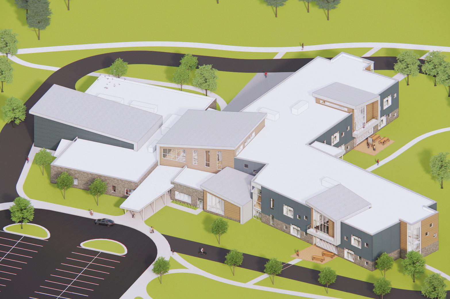
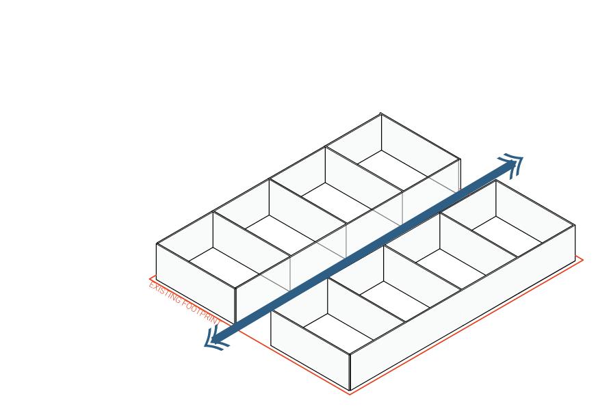
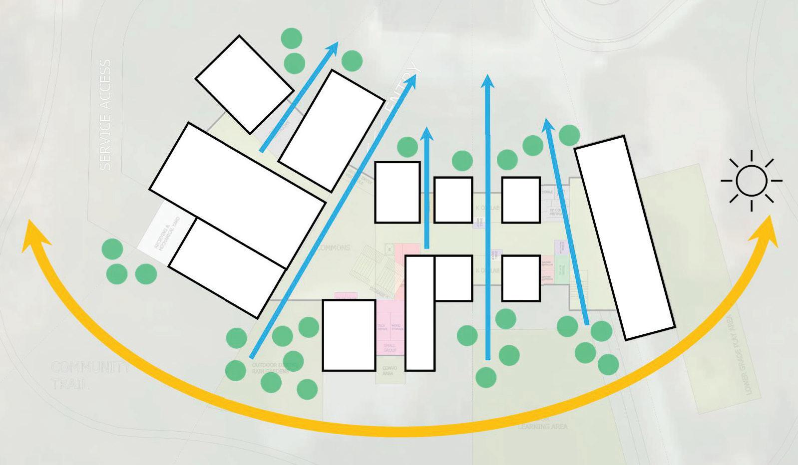
Plan Parti
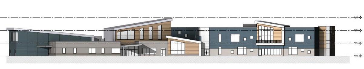
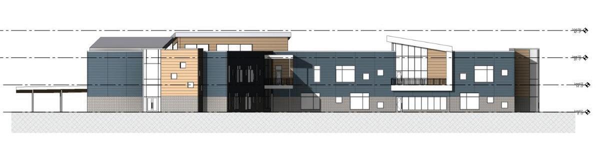
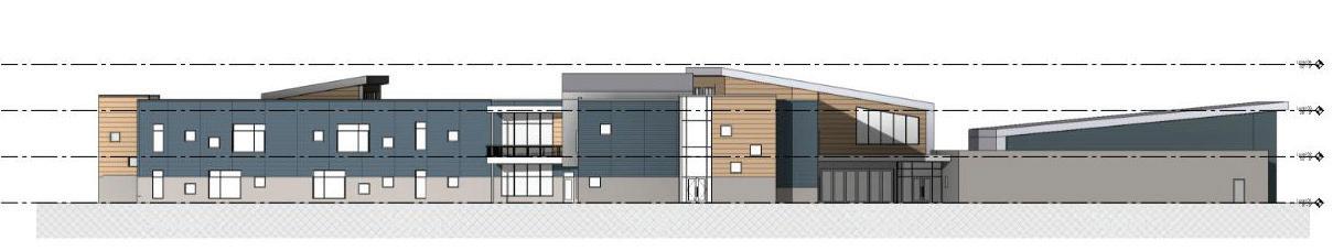
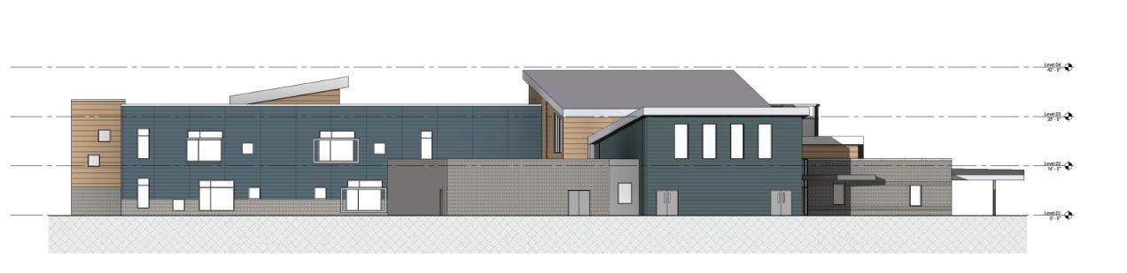
The required school program spaces are arranged to allow slices of light to penetrate though from north to south similar to daylight flowing through and around tree trunks in an oak savannah. Segmented massing of the b uilding spaces, and a soft bend in the floor plan help to break down the scale of the new two-story school and provide gestures to the scale of the neighborhood. Sloped roof forms above common use spaces illustrate the tree house concept and reflect the forms of the nearby homes. Student-shared flexible learning areas in the classroom wings will be expressed with such forms that frame views to the outdoors. Outdoor patios and decks extend from these spaces furthering the connection between students and nature.
Room with Storage
Coat Closet
Storage
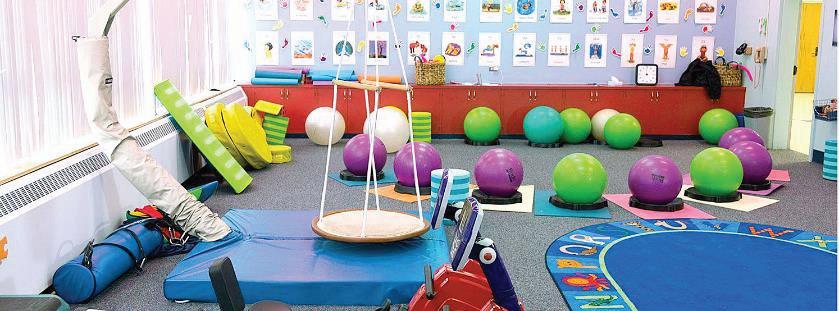
OT/PT
Sensory Room
Psychologist
Social Worker
Laundry/Lost Found Conference
Includes counter and files
12’x16’, desk area and small table for 4-6 person meeting
Shower for Staff that ride bikes to work and student accidents
Shared by Student Services
Files and copier inside work room
Office Supplies
11’x14’, desk area and small table for 3-4 person meeting 11’x14’, desk area and small table for 3-4 person meeting
use one in the office area
Kitchen/Serving
Cooler
Freezer
Commons/ Dining
Electrical
Mothers room
Social Worker
Psych
Closet
Nurse
Presentation
Laundry
Janitor
Storage
Gym/MultiPurpose
Shelter)
Receiving/ Storage
Flammables
Garden
Elec/MDF
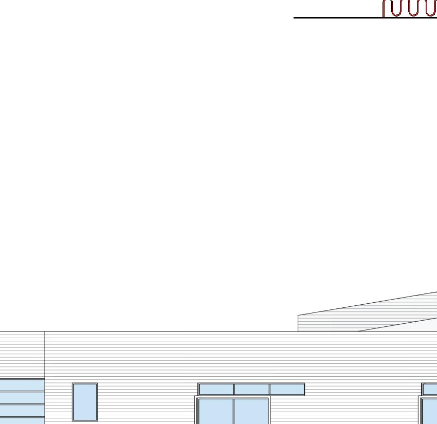
MAX ALLOWABLE AREA FOR PHOTOVOLTAIC PANELS
EPDM ROOF WITH PREFINISHED METAL COPING
SLOPED STANDING SEAM METAL ROOF SYSTEM
Roof top mechanical units, typ.
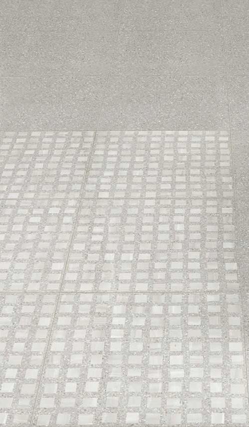
INTERIOR ENVIRONMENT
Interior Environment Narrative & Finish Schedule
INTERIOR ENVIRONMENT
All interior materials (including adhesives) to comply with CHPS guidelines. Refer to CHPS section for more information.
Flooring General Notes
Schluter metal transition trim pieces to be provided at all flooring transitions
Painting General Notes
Exterior and interior colors shall be selected by the Architect from manufacturer’s full range of colors and approved by AAPS.
All interior gypsum board walls and ceilings, doors, frames, exposed steel structural framing and connections, exposed metal ductwork and metal trim shall be painted with low V.O.C. coatings that are lead-free and chromatic-free.
High-performance coatings will be used in all spaces with moisture producing activities and for all exposed structural steel.
Epoxy paint to be used at interior stairwells, receiving, janitor, art classroom.
Manual roller shades are to be provided at exterior windows. Motorized roller shades to be provided at clerestory glazing and curtain wall locations in commons.
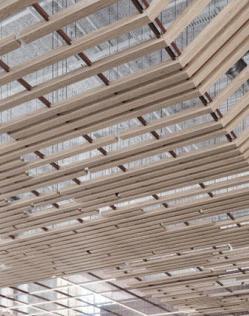
MILLWORK AND CASEWORK
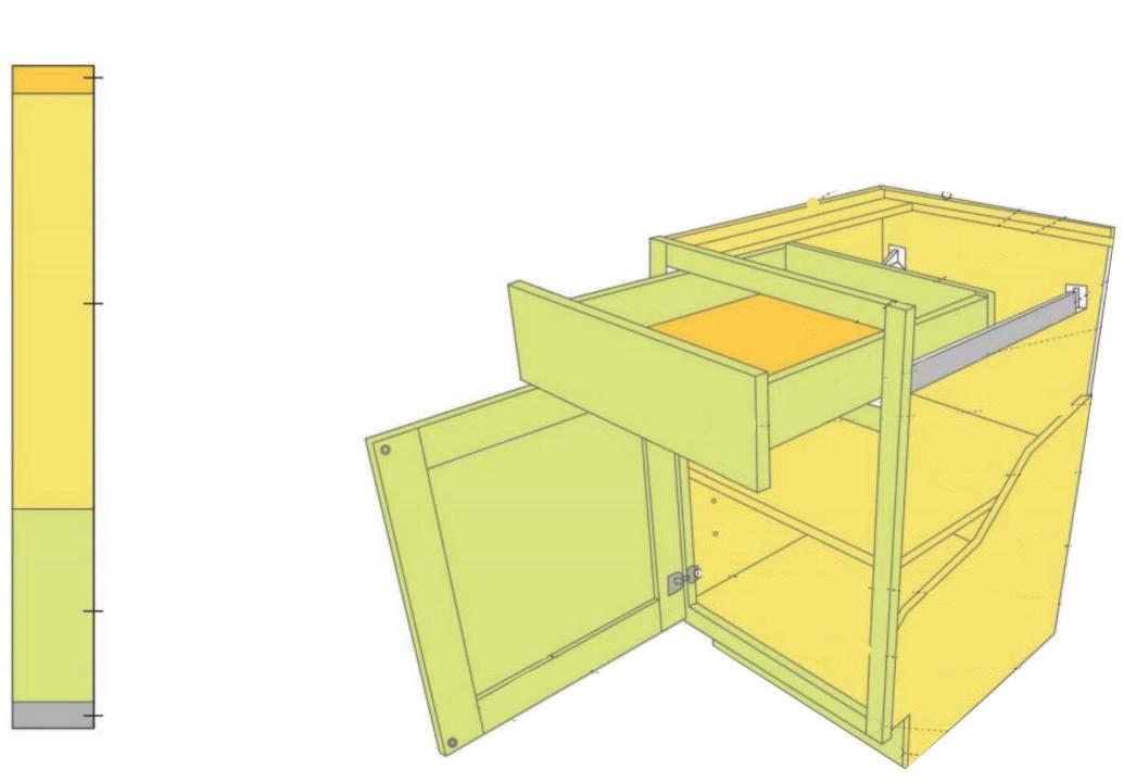
Casework to be constructed of hardwood-plywood and hardwood (see diagram below). Wood veneer with Quartz or manufactured stone countertops to be provided at specialty millwork and high-profile areas. Minimum standard for all other areas to be solid surface and any counters with a sink. Refer to Food Service section for additional information.
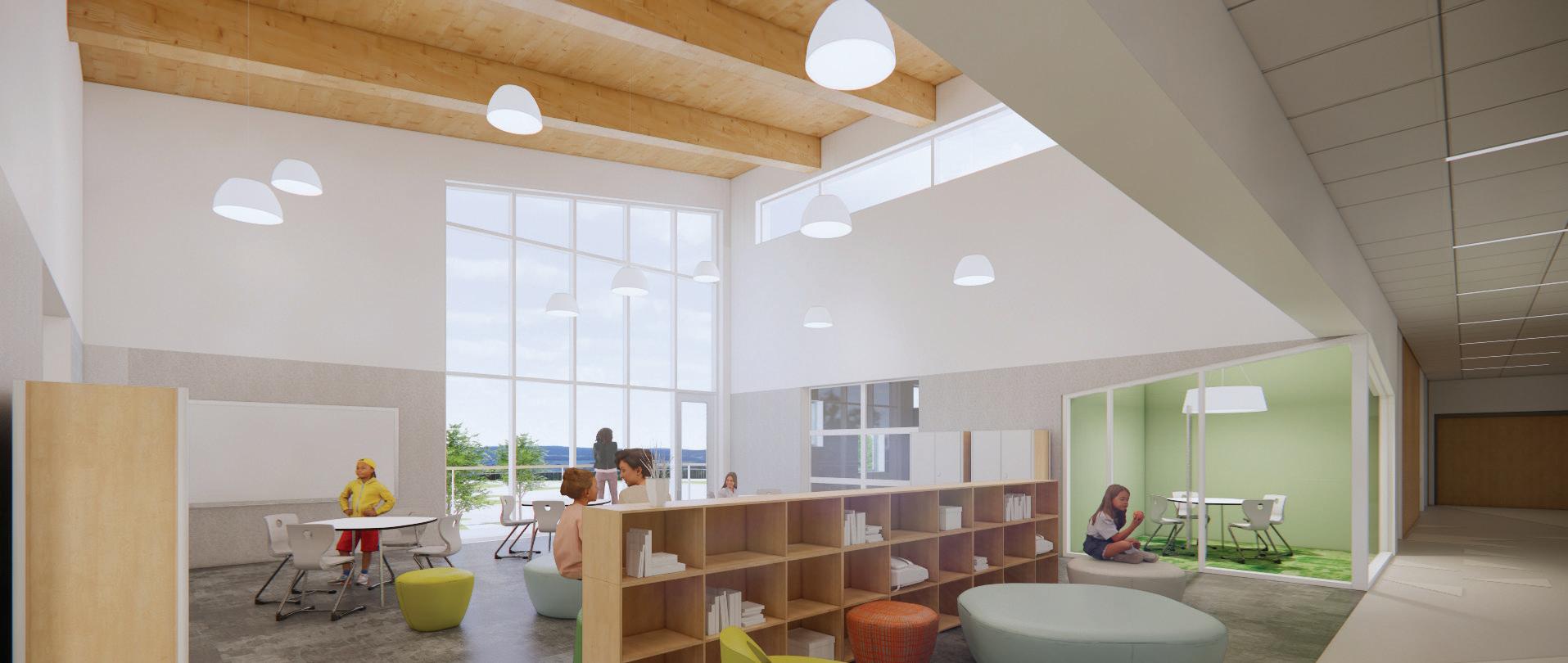
Millwork shelving and display features to be included in Media Center
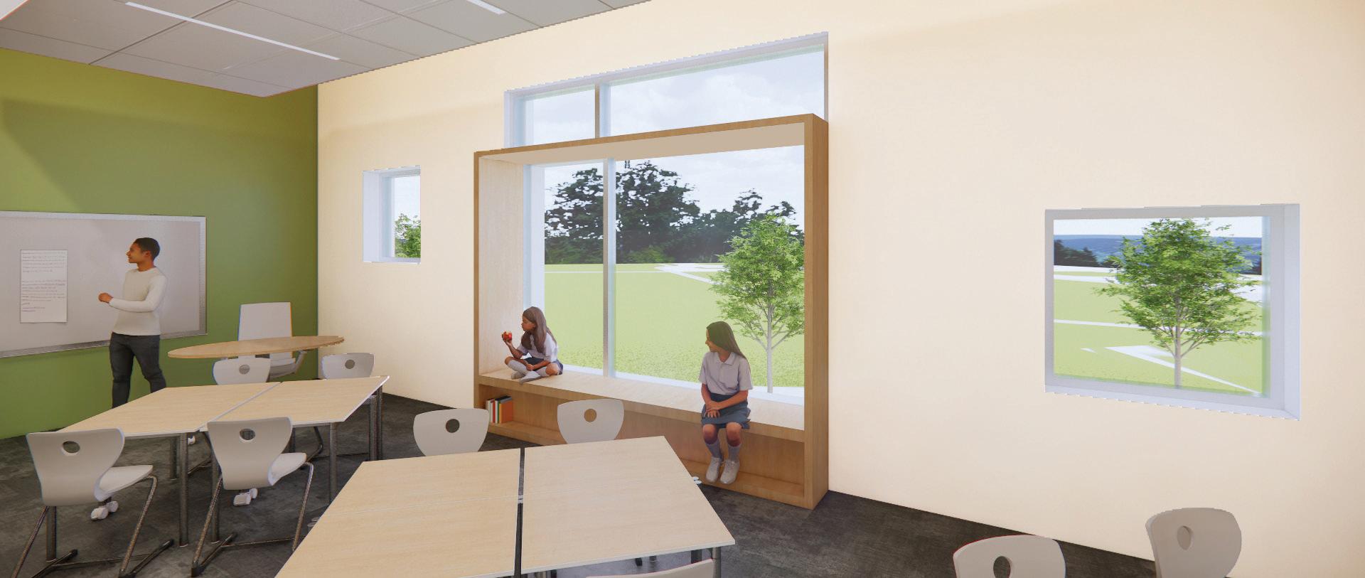
Millwork surround and bench to be included at typical Classroom exterior windows
Millwork cubbies and benches to be included in Coat Rooms
MISCELLANEOUS EQUIPMENT
Interior building signage will be designed to meet ADA requirements. All interior rooms will have plastic plaques with the room name and/or number located to meet ADA mounting heights.
Bathroom partitions to be full-height stud walls with sound batt insulation and full-height ceramic wall tile.
Wet walls at drinking fountains to be full-height ceramic wall tile.
FRP wall panels will be used at wet locations in custodial rooms.
Gym to have high impact athletic wall pads.
Wall Protection: Corner guards located through building at all gypsum wallboard corners. Surface-mounted, stainless steel, height 7 feet.
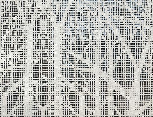
Markerboards, visual display boards, projection screens and tackable wall surfaces will be provided at the classrooms and conference rooms. Tack boards will be located in all classrooms, labs, offices and conference rooms.
Cubicles at Nurse Office: Cubicle tracks and curtains, basisof-design, General Cubicle Co.; anodized aluminum track and curtain curtains
Restroom accessories include framed mirrors, and stainless-steel disposal / dispenser units for toilet tissue, seat covers, etc. Paper towel dispensers, waste receptacles and soap dispensers are Owner-Furnished, ContractorInstalled items.
Unistrut utility grid will be provided select spaces with overhead cord reels.
Perforated metal and netting at typical guardrail locations
DOORS AND OPERABLE PARTITIONS
Interior doors to be solid core wood doors with selected hardwood face veneer and vision panels. All interior frames are to be aluminum with sidelites to the fullest extent possible. Doors to offices and classrooms without sidelites to hallways will have narrow glass vision panels.
Hardware shall be heavy-duty grade with necessary ratings and ADA egress hardware. Provide automatic door operators at main entrance vestibule and exterior café seating
FURNITURE, FIXTURES, AND EQUIPMENT
The following budget numbers should be held for a preliminary furniture budget. Existing furniture to re-use to be evaluated. Budget assumes reusing 50% of classroom furniture.
Typical SF Pricing Used:
Office/Admin Spaces $30/SF
Storage $15/SF
Classrooms $23/SF
Multipurpose, Media Center $30/SF
Specials (Art, Music) $25/SF
Furniture subtotal: $836,804
Install 12%: $100,416
Freight 6%: $50,208
Contingency 8%: $66,945
Escalation (3%/year = 9%): $75,312
Furniture Total: $1,079,478
*Freight currently shown as additional cost; however, VS includes freight in their pricing
7.
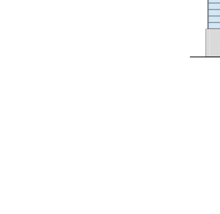
PRECAST CONCRETE PANELS
RIBBED FIBER CEMENT PLANK RAINSCREEN
CURTAINWALL WITH ANODIZED FRAME
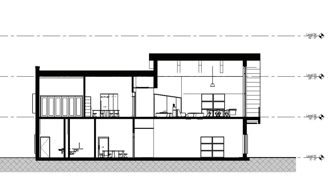
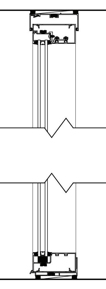
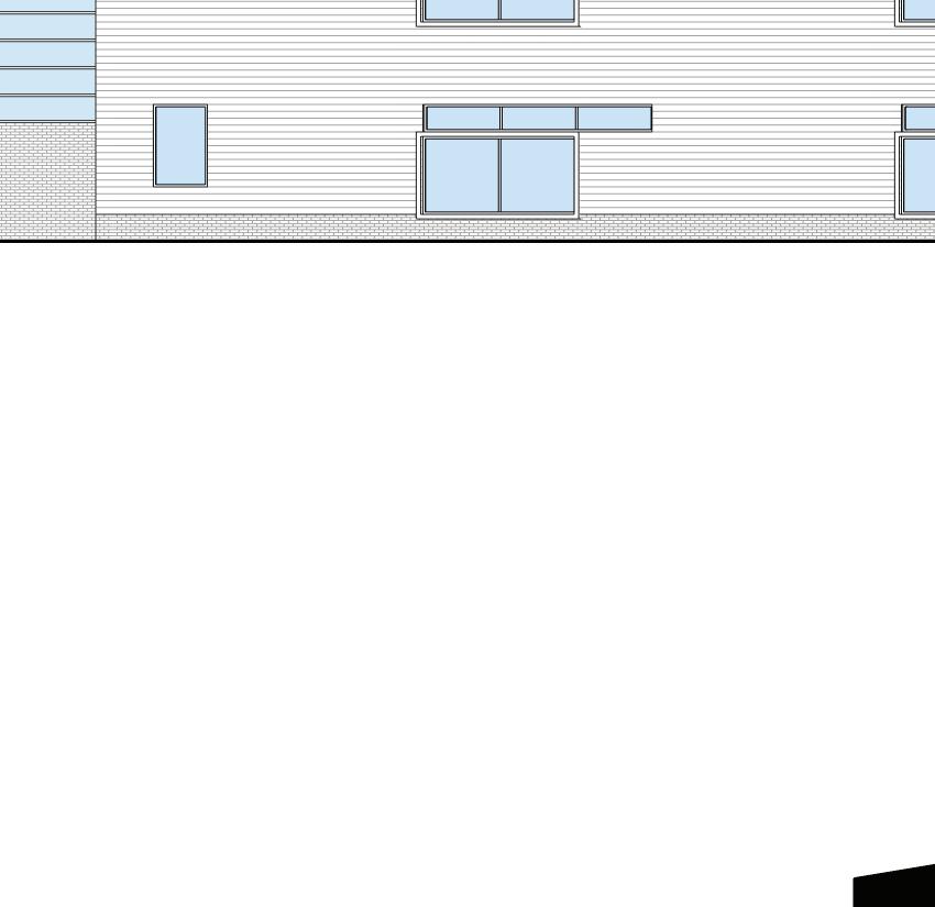
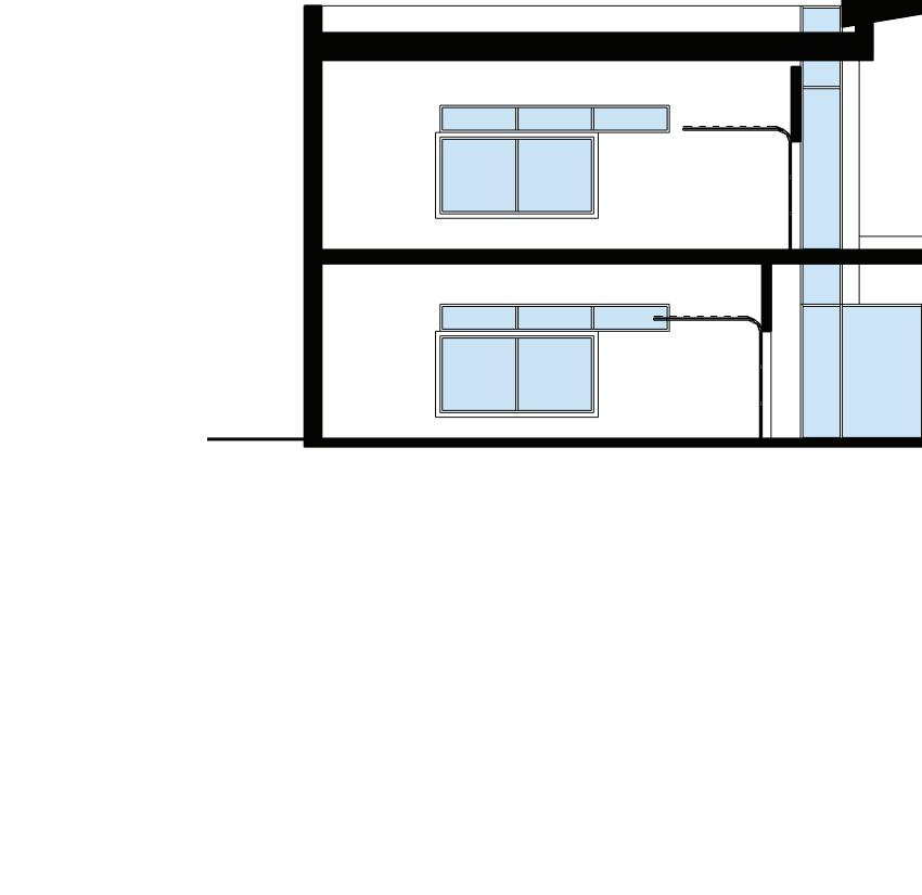
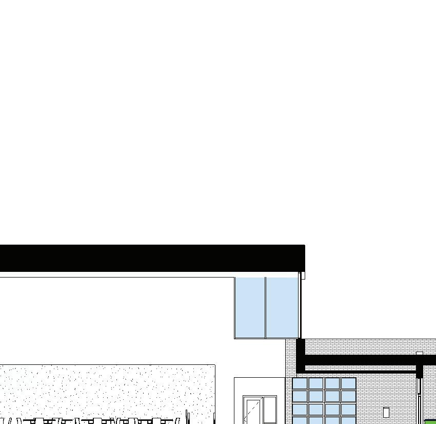
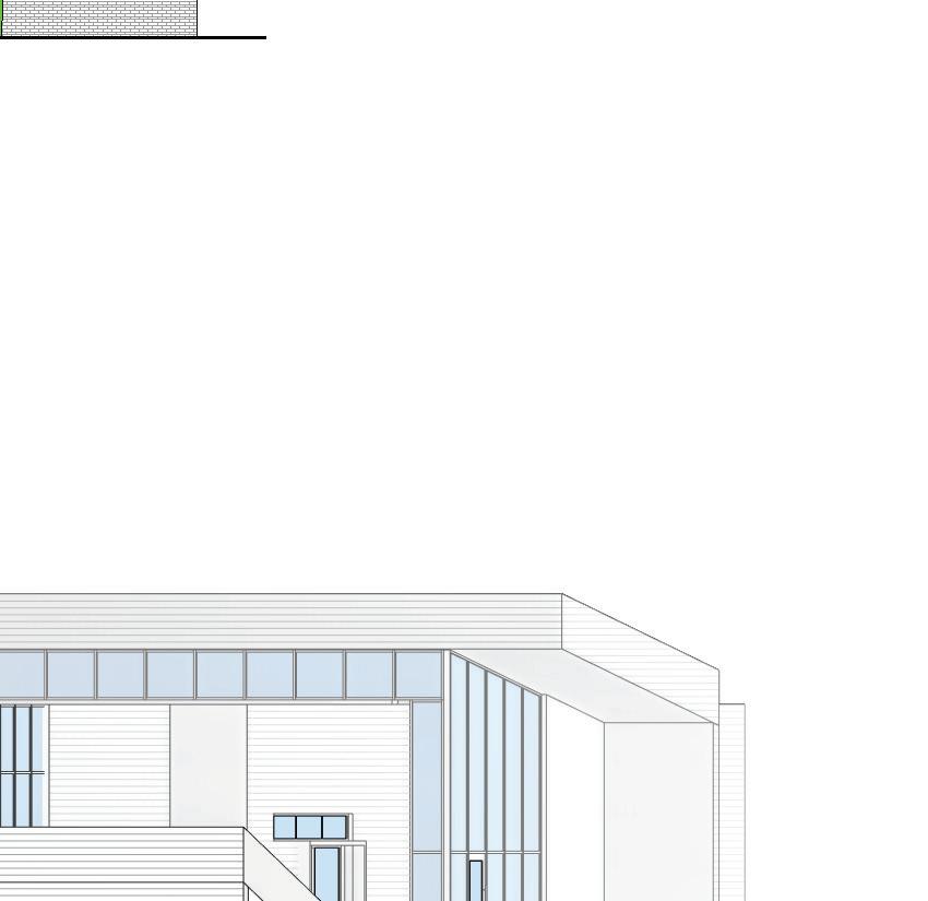
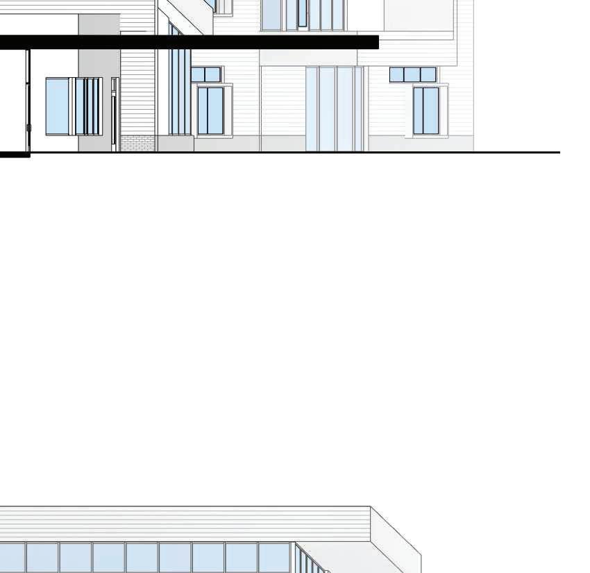
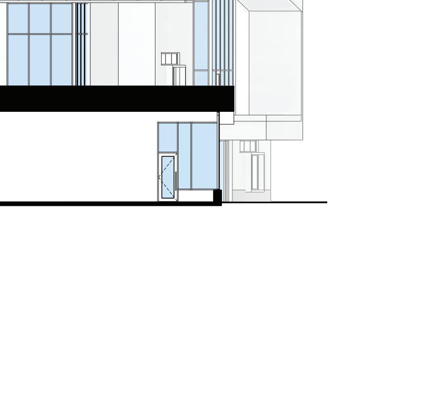
SECTION A - CLASSROOM & COLLABORATION SPACES
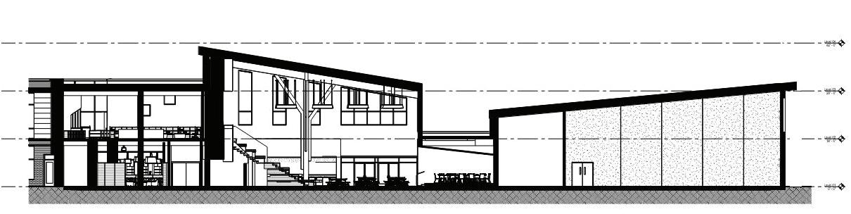
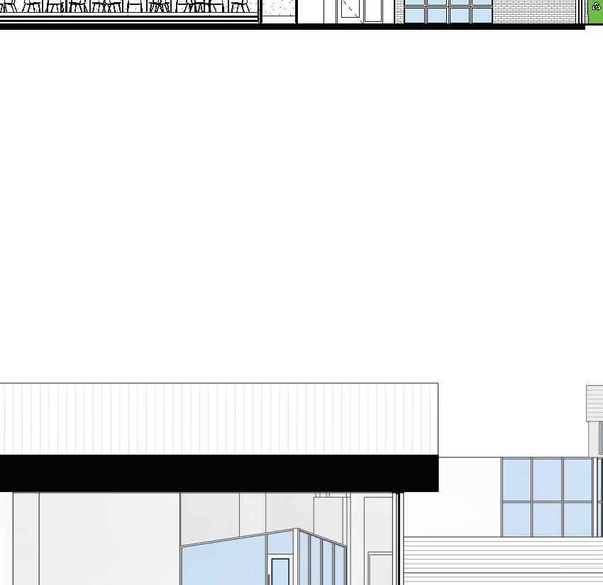
SECTION C - GYM & COMMONS
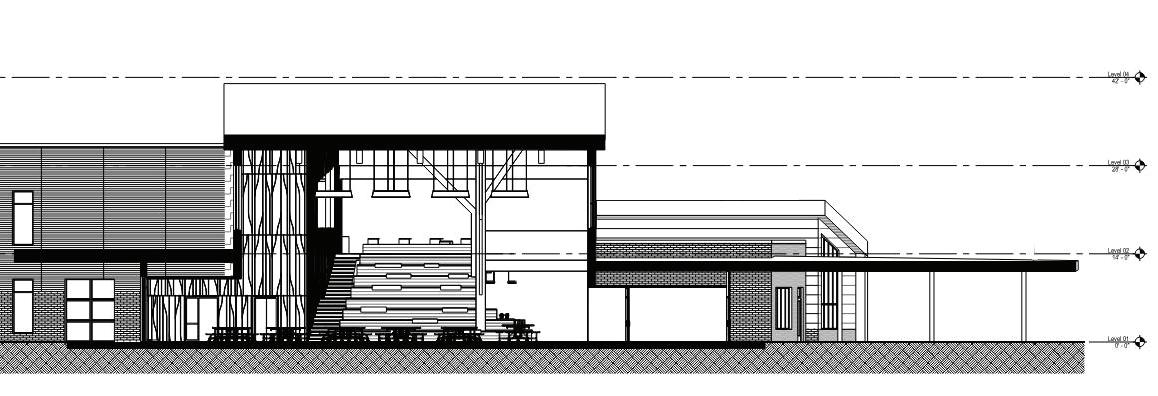
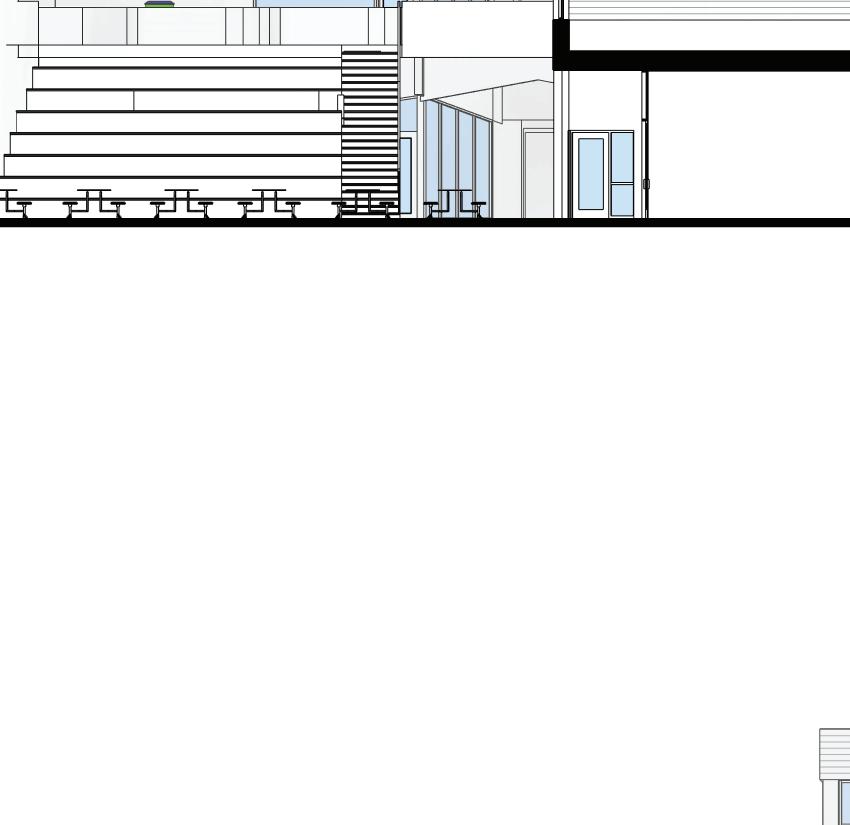
SECTION B - LEARNING STAIR & MAIN ENTRANCE
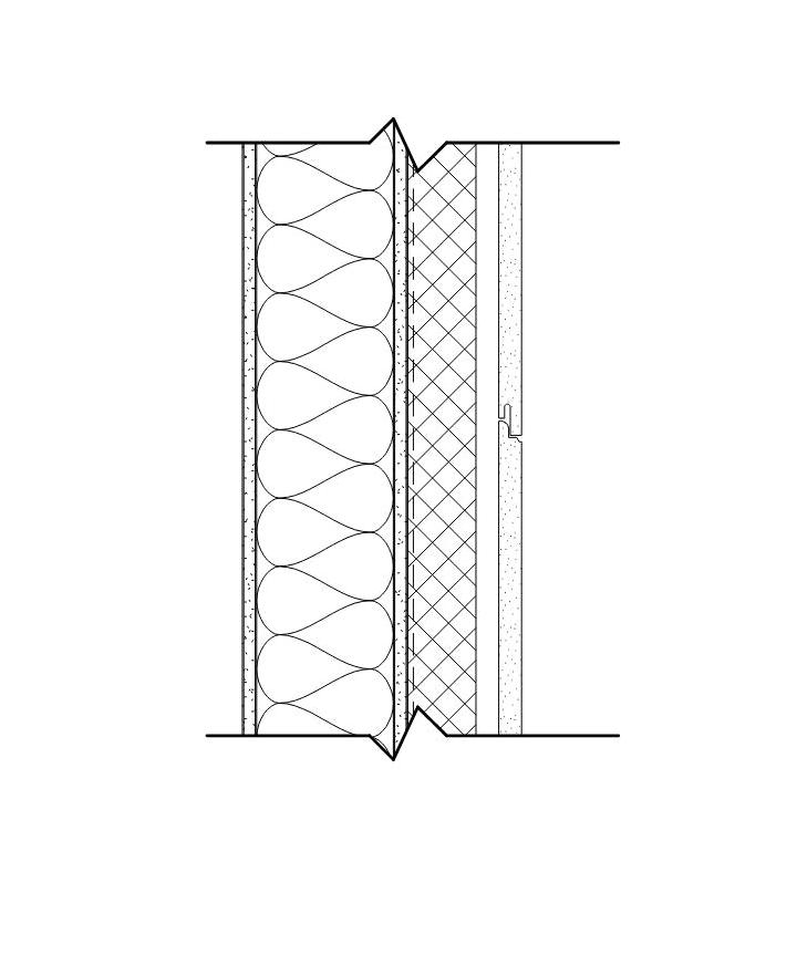
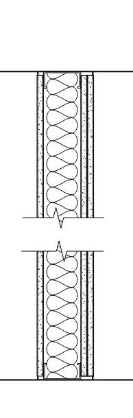
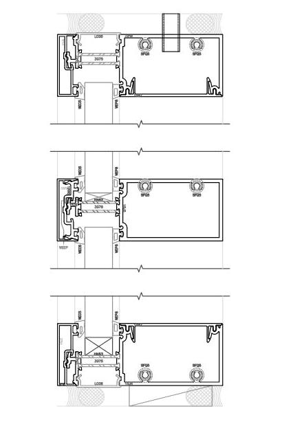
EXTERIOR WALL - FIBER CEMENT RAINSCREEN
The exterior wall construction is anticipated to consist of cold-formed metal framing with exterior gypsum sheathing with pre-applied air/water barrier. Cavity insulation is anticipated to be mineral wool. Façade panels will be anchored to composite framing members. Cold
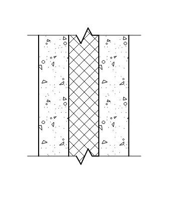
PRECAST PANEL
Exterior precast sandwich panel with continuous polyisocyanurate insulation, minimum R value of 11.4. Precast finish to include integral color and reveal patterns.
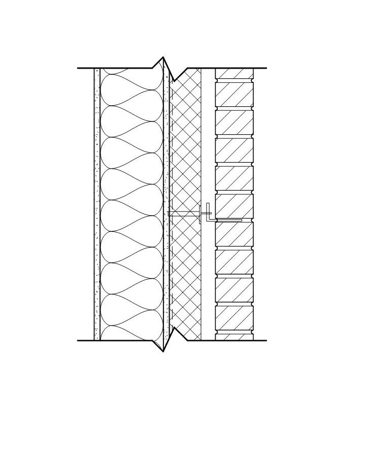
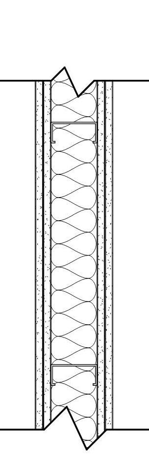
EXTERIOR WALL - BRICK VENEER CAVITY WALL
The exterior wall construction is anticipated to consist of cold-formed metal framing with exterior gypsum sheathing with pre-applied air/water barrier. Cavity insulation is anticipated to be mineral wool. Brick will be anchored to composite framing members. EXTERIOR WALL -
Metal Panels
Self Adhering, high temperature underlayment
Standing seam metal panels will be the roofing covering for the sloped roof areas including the Gymnasium, Flexible Learning Environments, Music Room and the Commons. Provide self-adhering, high-temperature underlayment of minimum 30 mils thickness. Provide manufacturer’s standard sections for support, alignment, and attachment of the metal panel system. Provide gutters and downspouts formed from the same material as the roof panels and finished to match. Gutters and downspouts shall be compliant with SMACNA standards. Provide gypsum cover board and minimum R30 rigid insulation over vapor barrier.
Cold form metal framing Brick
Building Assemblies
Storefront
Curtainwall
For low-slope roof areas provide single-ply fully adhered roofing membrane of EPDM or TPO over cover board and minimum R-30 rigid insulation and vapor barrier. Provide an additional layer of membrane under each foot of the ballasted solar panel system.
For roofing accessories, assume walkway pads, thermally broken roof hatches, aluminum roof ladders and factory finished coping.
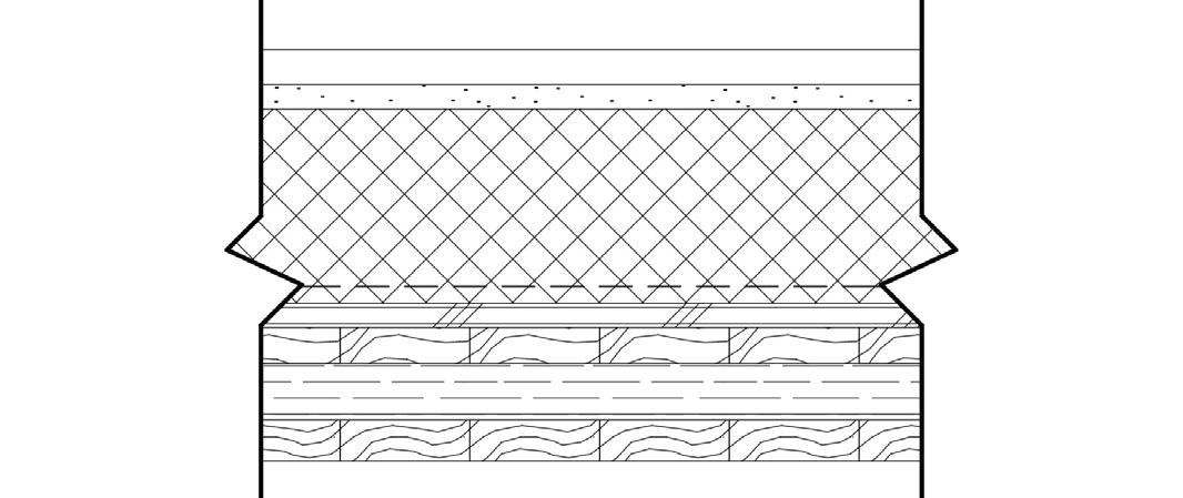
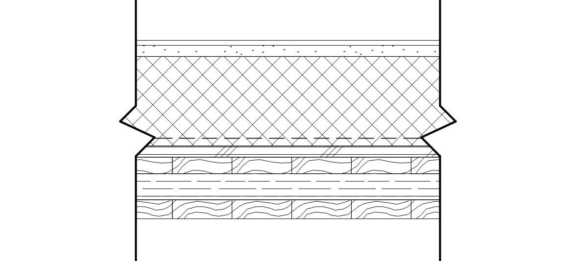
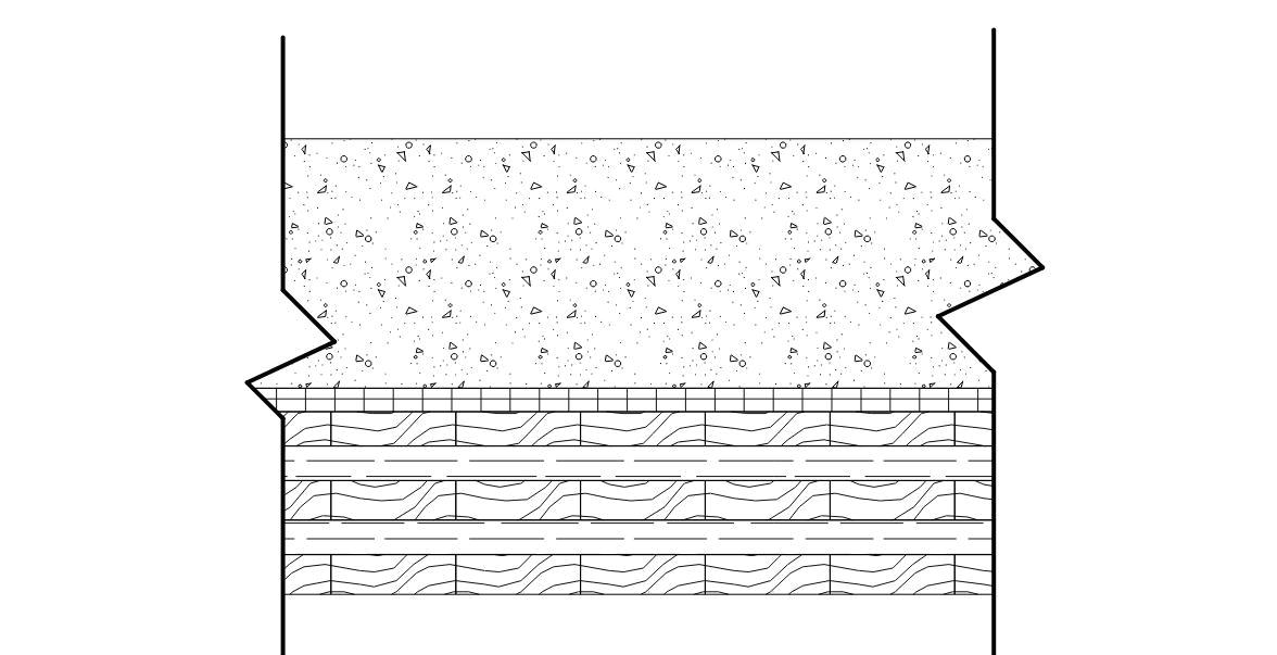
FLOOR SLAB
The floor system will consist of 4-1/8” CLT slabs with steel beams supporting the slab.
Glulam beams and/or flitch beams (composite steel/timber members) will be used in lieu of steel beams in certain areas of the building’s roof system.
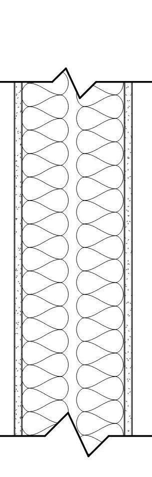
Interior partitions to be steel stud with deflection compensation head tracks. Assume 3 total layers of gypsum board between classrooms. All interior partitions should include acoustical batt insulation and acoustically rated sealant at head and base.
STC 46 - Walls between classrooms
STC 53 - Walls between toilet rooms & classrooms
STC 60 - Walls between classrooms & mechanical spaces
GLAZING SYSTEMS
Provide thermally broken aluminum curtainwall and storefront framing systems of either clear anodized, or high performance coating (ex. Kynar). Provide insulating glass units with insulating airspace and clear annealed float glass or fully tempered or heat strengthened as required. Low-e coating anticipated on surface #2. Refer to the Climate and Environment section for the glass performance characteristics.
For punched window openings in the gymnasium precast walls, tornado-resistant window system and glass panels in accordance with FEMA requirements are anticipated. In aluminum storefront or curtainwall systems provide thermally broken, insulated aluminum doors, medium stile with insulated glazing units including laminated and tempered safety glazing. For service doors provide thermally broken, insulated, corrosion resistant hollow metal doors and frames. For exterior overhead doors provide a motorized insulated coiling overhead door with custom color baked enamel or powder coat finish.
Provide a Multipanel Folding Aluminum Framed Glass Door at the south east wall of the Commons.
The governing codes enforced by Michigan Department of Licensing and Regulatory Affairs (LARA) current construction codes are as follows:
Construction of School Buildings Act 306 of 1937
2015 Michigan Building Code-International Building Code 2015 (IBC 2015 with amendments)
2018 Michigan Plumbing Code
2015 Michigan Mechanical Code
Michigan Electrical Code based on the 2017 National Electrical Code w/ Part 8 State Amendments
2015 International Fire Code
2010 NFPA 13, 13D & 13R
2013 NFPA 72 Fire Alarm Code
Accessibility and universal design are governed by both 2009 ICC A117.1 Accessible and Usable Buildings and Facilities and the Michigan Barrier Free Design Law of Public Act 1 of 1966 as amended.
Energy conservation is governed by both the 2016 International Energy Conservation Code Part 10 with ANSI/ASHRAE/IESNA Standard 90.1-2013 and the 2015 Michigan Energy Code
2015 Michigan Energy Code; 2015 IECC and ASHRAE 90.1.2013
Additionally, The Bureau of Fire Safety (BFS) enforces the following codes:
2012 Michigan Life Safety Code; New and Existing School, College, and University Fire Safety Rules adopted May 19, 2016, including: National Fire Protection Association Pamphlet No. 101, 2012 edition, “Life Safety Code” with amendments.
BUILDING OCCUPANCY USE TYPE
The building occupancy use group will be defined in both Michigan Building Code as follows.
Educational Group E (Elementary School grades K through 5) (MBC 2015)
Additional occupancy groups to include:
Group S-1 Accessory (Moderate-hazard storage)
Group A-2 Accessory (Commons dining)
Group A-3 Accessory (Multi-Purpose Gym, Media Center)
Group B Accessory (Administration)
BUILDING OCCUPANCY USE TYPE, CONT.
Per NFPA 101-6.1.14 each portion of the building shall be classified as to its use in accordance with Section 6.1. The building shall comply with the most restrictive requirements of the occupancies involved unless separate safeguards are approved (6.1.14.3.2). Therefore, the Occupancy Use Type for NFPA 101 shall be as follows:
Mixed-Use – Educational and Assembly (NFPA 101-2012)
BUILDING CONSTRUCTION TYPE
Per Michigan Building Code 2016 Chapter 6, the building will be classified as Construction Type III-B. The fire rating requirements from Table 601 are as follows:
Building Element Rating in HRS
Primary Structural Frame
Bearing Walls-Exterior
Bearing Walls-Interior
Nonbearing Walls
Floor Construction
Roof Construction
Note: MBC Table 601 Footnote C: “In all occupancies, heavy timber shall be allowed where a 1-hour or less fireresistance rating is required.
MBC Table 601: Type III-B
MBC 602.3 Type III: Exterior walls are noncombustible materials, interior building elements are of any material permitted by code.
NOTE: Current MBC Type III-B Group E Occupancy currently allows wood, including mass timber, to be utilized for Interior Framing Materials, Primary Framing, Floor Framing and Roof Framing members.
BUILDING HEIGHT AND AREA LIMITATIONS
Per Michigan Building Code 2015, Table 506.2 the allowable area for a fully sprinklered multi-story building of Type III-B construction is as follows:
Limitation on building area: 43,500 ft2 43,500 ft2 for Educational Occupancy Classification
BUILDING HEIGHT AND AREA LIMITATIONS, CONT. MEANS OF EGRESS
Per Michigan Building Code 2015, Table 504.4 the allowable number of stories for a sprinklered building of Type III-B construction classified as an Educational Occupancy is as follows.
Limitation on number of stories: 3
Anticipated number of stories: 2
Per Michigan Building Code 2015, Table 504.2 the allowable building height above grade for a sprinklered building of Type III-B construction classified as an Educational Occupancy is as follows.
Limitation on building height: 75’ above grade plane Anticipated building height: 41’-6”
COMMUNICATING SPACE
The Michigan Life Safety Code including NFPA 101-2012 permits a Communicating Space provided the following conditions are met:
Does not connect more than 3 contiguous stories. Lowest (or next-to-lowest) story is a street floor.
Entire floor area is open and unobstructed, such that a fire in any part of the space will be readily obvious to occupants prior to time it becomes a hazard.
If building protected by sprinkler system, a smoke barrier shall be permitted to serve as separation requirement.
Egress capacity sufficient to allow all occupants of all levels within space to simultaneously egress by considering it as single floor area in determining required egress capacity.
Each occupant within space has access to not less than one exit without having to traverse another story within communicating space.
Each occupant within space has access to not less than one exit with having to enter communicating space.
It is currently anticipated that all conditions will be met with the exception of the entire floor area being open and unobstructed. It is expected that a variance request using the Life Safety Code of 2021 will be required.
Occupant loads will be calculated based on Michigan Building Code 2015, table 1004.1.2.
Per Michigan Building Code 2015, table 1006.3.1, the minimum number of exits required will be based on the total occupant load calculated per story. A total occupant load of between 500 and 1000 is anticipated at this point that will require 3 exits. Current plans anticipate 3 exit stairs discharging directly to grade from the second level with an additional 5 exits from the first level.
Minimum corridor width of 72” is required by both the Life Safety Code and the Michigan Building Code 2015. Egress stairs shall be sized to 0.2 inches per occupant and corridors and egress doors shall be sized to 0.15 inches per occupant.
Travel distance access to the exits is restricted to a maximum of 250’ for a fully sprinklered building per Michigan Life Safety Code 2012, section 14.2.6.3. The maximum for dead end corridors in a fully sprinklered building is 50’. Maximum common path of travel is limited to 75’ for a fully sprinklered building.
MINIMUM INTERIOR FIRE RESISTANT RATINGS
Minimum fire resistance ratings for interior partitions shall be as follows:
1 hour barrier:
Egress Stair Enclosure partitions
Elevator enclosures
Storage areas greater than 100 ft2
Storage areas for contents requiring a rated enclosure
Separation between Assembly and Educational Occupancy (per NFPA 101, 6.1.14.4)
Smoke Barrier (per Michigan Life Safety Code 2015, Section 8.6.6(4)
Communicating Space enclosure
Openings which are not smoke rated are to be protected with smoke curtains.
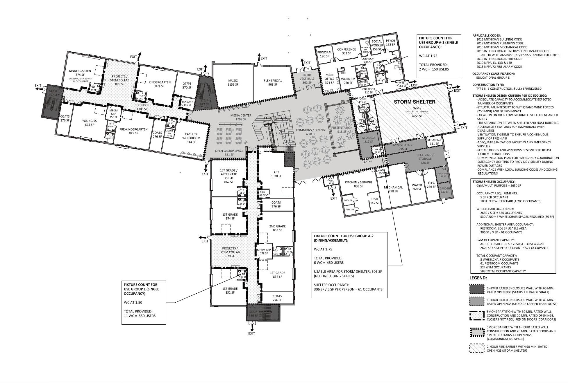
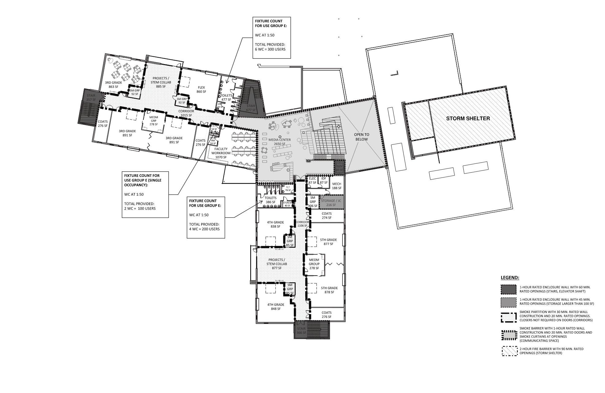
STORM SHELTER
Under the current 2015 Michigan Building Code, storm shelter requirements for Group E Occupancies are excluded. If Michigan adopts the 2021 International Building Code with amendments, educational projects with an occupant load of 50 or more may be required to incorporate storm shelters within the 250 MPH wind zone. The location of Dicken Elementary School falls within the 250 MPH wind zone.
If storm shelters are required, they must meet ICC 500 requirements. It is anticipated that the proposed gymnasium will be designed in accordance with ICC 500 requirements. The required occupant capacity for a new Group E occupancy shall include all buildings on the site and shall be the greater of the total occupant load of classrooms, vocational rooms and offices or the occupant load of the largest indoor assembly space. For community storm shelters, 5 SF must be provided for every standing or seated occupant, and 10 SF must be provided for every occupant using a wheelchair.
MEMBERS
Regulations of Local Utilities Providers
American Refrigeration Institute (ARI)
American Society of Heating, Refrigeration, and AirConditioning Engineers, Inc. (ASHRAE)
American Society of Mechanical Engineers (ASME)
American Water Works Association (AWWA)
National Fire Protection Agency (NFPA)
Occupational Safety and Health Act (OSHA)
Sheet Metal and Air Conditioning Contractors
National Association, Inc. (SMACNA)
American National Standards Institute (ANSI)
American Society for Testing and Materials (ASTM)
Associated Air Balance Association (AABC)
Energy Policy Act of 1992 (EPACT92)
Underwriters’ Laboratories (UL)
LIST OF ALL APPLICABLE CODES
2015 Michigan Building Code
2015 Michigan Mechanical Code
2018 Michigan Plumbing Code
2015 International Fire Code
2015 International Energy Conservation Code Part 10 with ANSI/ASHRAE/IESNA Standard 90.1-2013
2015 International Fuel Gas Code
2014 NFPA 96 Grease Hoods
2010 NFPA 13, 13D & 13R
2020 ICC 500 Standard for the Design and Construction of Storm Shelters
ASCE 7-10 “Minimum Design Loads for Buildings and Other Structures”
ACI 318-14 “Building Code Requirements for Structural Concrete”
AISC 360-10 “Specification for Structural Steel Buildings”
ACI/MSJC 530-13 “Building Code Requirements for Masonry Structures”
AISI S100-12 “North American Specification for the Design of Cold-formed Steel Structural
OVERVIEW
Quality acoustical environments are required in school facilities to facilitate student learning and occupant health. The hybrid mass timber, steel, and precast concrete structure proposed for the building design presents many unique acoustical challenges to address during design.
DESIGN CRITERIA
The new Dicken Elementary School will be designed according to the CHPS Verified leader program. CHPS EQ15.0 Acoustical Performance Prerequisite includes the requirements for room finishes and reverberation time, background noise from HVAC systems and the exterior environment, internal sound transfer between rooms. The CHPS criteria is based on ANSI/ASA Standard S12.60-2010 with specific amendments and clarifications.
The criteria utilized for this project are summarized below. Alternative design methods to meet CHPS compliance are available in some instances and will be considered as the design progresses. Note that CHPS acoustical criteria focuses only on Core Learning Spaces, additional spaces in the building will be designed and considered following other industry guidelines.
SOUND REVERBERATION
Both a Performance and Prescriptive Method are provided for compliance paths, and we recommend following the Prescriptive Method currently.
Prescriptive Method
Core learning spaces with volume less than 10,000 ft3: Ceiling finish with a minimum NRC of 0.70, covering minimum 95% of ceiling area (excluding lights, diffusers and grilles).
Core learning spaces with volume between 10,000 ft3 and 20,000 ft3: Ceiling finish with a minimum NRC of 0.70, covering minimum 85% of ceiling area (excluding lights, diffusers and grilles).
Non-Core learning spaces such as offices, learning star, cafeteria, and gymnasium will be designed with acoustical finishes to achieve appropriate reverberation time performance according to the use and size of each space.
BACKGROUND NOISE
In Core Learning Spaces and in spaces designated as InterClassroom Workspaces and Special Education Rooms, the total background noise from the combination of building HVAC systems and exterior noise shall not exceed 40 dBA.
Non-Core learning spaces will be designed according to background noise criteria guidelines from the ASHRAE 2023 HVAC Applications Handbook.
SOUND ISOLATION (INDOOR TO INDOOR)
Sound isolation will be designed according to CHPS Tables EQ15-1 & 15-2, an excerpt of the criteria is provided here for reference:
Classroom, ICWS, SER
Classroom, ICWS, SER
Classroom, ICWS, SER
Mechanical Equipment Room Corridor
Classroom, ICWS, SER
Classroom, ICWS, SER
Classroom, ICWS, SER
Classroom, ICWS, SER
Operable partitions shall have the same STC rating as the wall they replace.
Interior glazing in walls with STC 40 or higher shall have the same minimum STC requirement as the wall.
Communicating doors between Classrooms must meet STC 40 ratings.
Impact Insulation Class (IIC) ratings for floor-ceiling assemblies of normally occupied room located above core learning spaces must meet IIC 45 minimum performance.
PERLIMINARY MATERIAL QUANITIES
The following material quantity estimates are provided to assist in early cost estimating for the project:
Typical Core Learning Space:
75% of the ceiling area will be absorptive APC style cloud, and an addition 20% of the floor area requires 1” thick acoustical wall panels. (i.e. a 1000 sf room requires 750 sf APC + 200 sf 1” thick wall panels)
Music Classroom:
75% of the ceiling area will be absorptive APC style cloud, and an addition 500 sf of 2” thick acoustical wall panels.
Office, Conference Room: APC + wall panels = 100% of floor area
Gymnasium:
2500 sf of 2” thick impact resistant acoustical wall panels
2000 sf of 2” thick impact resistant acoustical ceiling panels
Cafeteria/Learning Stair/Media Center:
Total acoustical treatment = floor area of the combined spaces (combination of baffles, wall panels, etc.)
TECHNICAL INFORMATION - CLIMATE & ENVIRONMENT
CLIMATE AND ENVIRONMENT - PROJECT GOALS
Goal 1: Operational Performance & Decarbonization
The project aims to design a Net Zero Ready building by integrating optimized energy solutions, without sacrificing the user experience. The project aims to focus on performance of the building while driving the project towards net zero, low carbon and low EUI* in operation. *Site Energy Use Intensity (EUI) is a measure of a building’s gross annual site energy consumption (including all fuels) relative to its gross square footage. The units are kBtu/sf/ year.
Goal 2: Achieve CHPS Certification
Dicken aims to pursue Collaborative for High Performance Schools (CHPS) certification at the Verified Leader. A CHPS Administrator will oversee design and construction teams to ensure all necessary project documentation is submitted for certification.
Goal 3: Operation Performance & Decarbonization
ENERGY TARGETS OVERVIEW
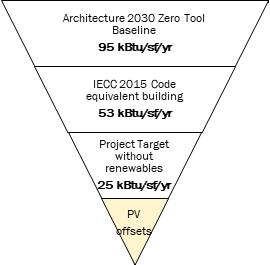
The building energy metrics for this project have been compared against buildings of this type in the region using data reported in the Architecture 2030’s voluntary Zero Tool program. The Zero Tool calculates fossil fuel energy consumption for existing buildings and new building designs and normalizes a building’s performance for comparison to reduction targets and other buildings. The tool analysis engine uses the CBECS 2003 dataset.
The Zero Tool reported median for a K-12 School building in Ann Arbor, MI with an Energy use intensity (EUI) of 95 kBtu/ ft2/yr. A typical K-12 building designed to IECC 2015 codes will report an EUI of about 53 kBtu/ ft2/yr.
The goal for the project would be to reduce the overall energy by optimized use of different climate responsive, sustainable design strategies. To meet the project’s Net Zero Ready goal while complying with the IECC 2015, the project targets achieving an Energy Use Intensity (EUI) of 25 kBtu/ft2/yr and then use solar PV to drive the targeted building EUI to zero.
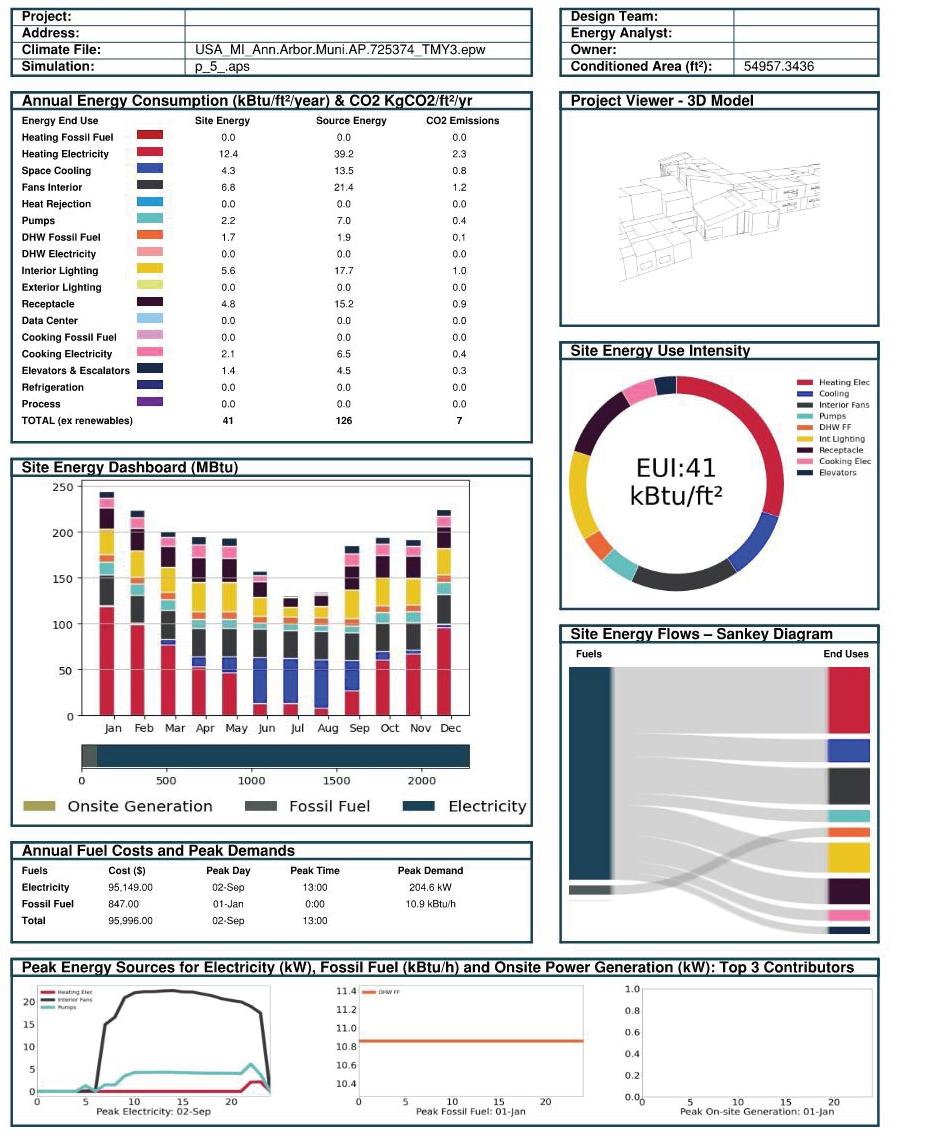
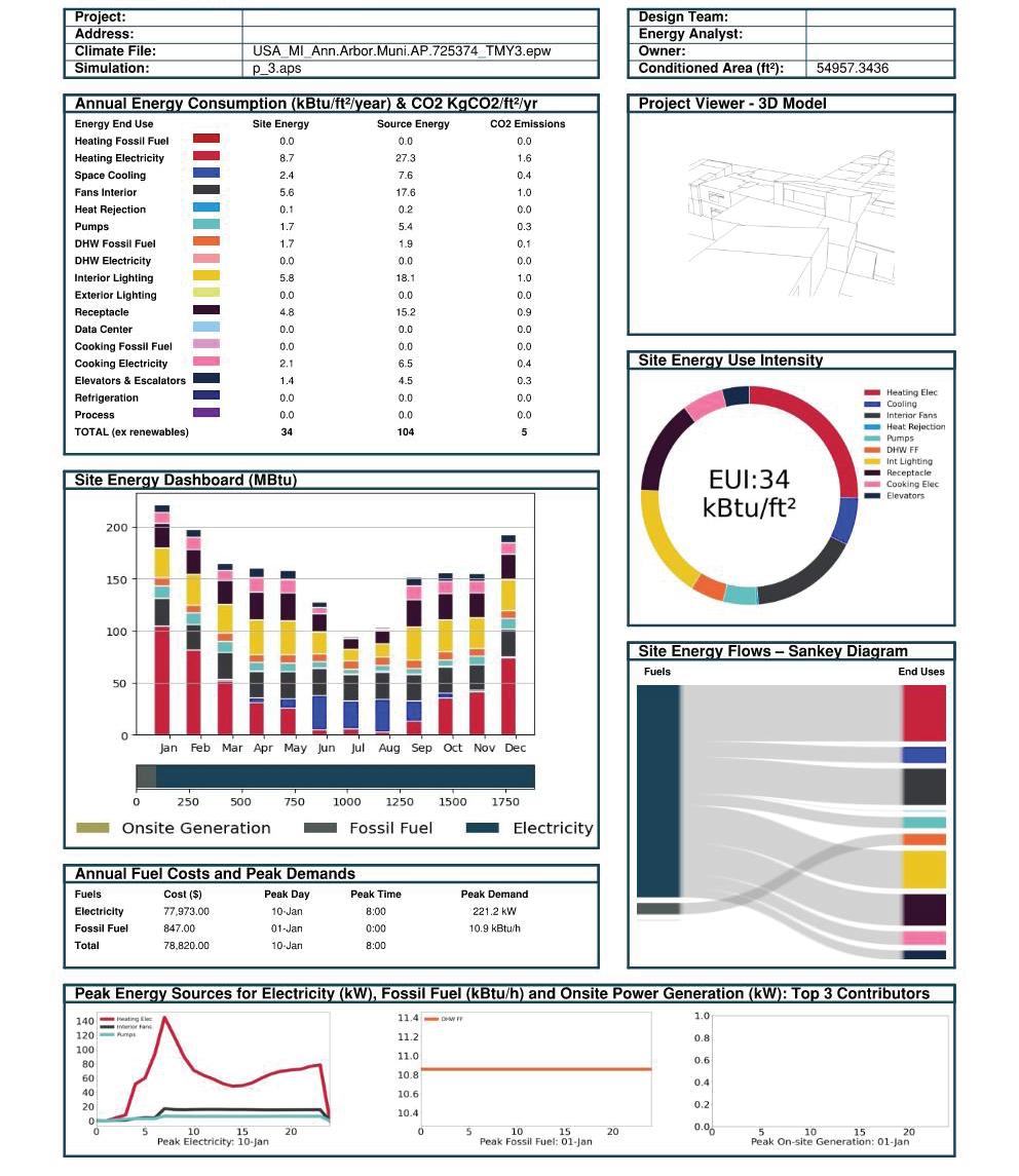
ENERGY PERFORMANCE MODELING
A preliminary energy model was developed using Integrated Environmental Solutions Virtual Environment (IESVE 2023), predictive computer modeling software to reflect an ASHRAE 90.1 2016 baseline for the building design and alongside study different energy efficiency strategies to drive the design towards an optimized energy solution and meet the net zero ready target. The software is used to calculate energy consumption on an hourly basis over a period of one year using the Ann Arbor Airport, MI weather file.
Building Performance Information
ENVELOPE (REFER TO ARCHITECTURE)
Baseline design: The baseline model considered IECC 2015 code prescriptive values for the envelope properties.
Roof: Insulation Entirely Above Deck: R-30
Exterior Walls: Metal Framed: R-13 + R-7.5ci Glazing: Fixed Fenestration assembly U value: 0.38; SHGC for South, East & West Facing windows: 0.40 and North Facing windows 0.53 Window to wall area: 15% for all the studied models.
ENERGY PERFORMANCE MODELING
A preliminary energy model was developed using Integrated Environmental Solutions Virtual Environment (IESVE 2023), predictive computer modeling software to reflect an ASHRAE 90.1 2016 baseline for the building design and alongside study different energy efficiency strategies to drive the design towards an optimized energy solution and meet the net zero ready target. The software is used to calculate energy consumption on an hourly basis over a period of one year using the Ann Arbor Airport, MI weather file.
ENERGY EFFICIENCY MEASURES (ECM) EVALUATED
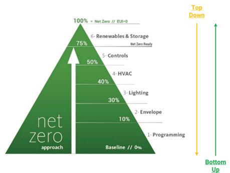
This section covers the different energy efficiency strategies explored on the project. The project uses bottom-up strategy to explore the different energy efficiency strategies to reduce the building energy consumption first and then offset the energy needs by on-site PV system.
Studied ECMs: Roof with insulation value R40 and external walls with assembly R value of R20 were studied. These studies showed minimal impact in reducing the EUI for the building.
Other recommendations:
Explore reducing the assembly U value of the fenestrations while balancing with the daylighting levels in the building.
Explore the use of transpired solar collectors on the south façade of the building for preheating the outside air.
Explore the potential of reducing infiltration through the building facade.
Building Performance Information
Baseline design: The baseline model considered a whole building lighting power density (LPD) of 0.7 W/sf.
Studied ECM: design team will use space by space lighting thresholds from IECC 2015 but aims to reduce the whole building lighting power density (LPD) from 0.7 W/sf to 0.5 W/sf. (Refer to the electrical narrative for more details.)
Other recommendations:
LIGHTING MECHANICAL SYSTEMS
Daylighting - optimize daylighting through effective façade design and programming to ensure artificial lighting can be switched off during the daytime.
Reduce the exterior lighting by 10-15% below code minimum values.
Comparative Baseline System: The baseline model considered ASHRAE 90.1 2016 Appendix G System 5Packaged VAV with reheat, with direct expansion cooling and hot-water fossil fuel boiler heating.
Studied ECMs: Five (5) different HVAC systems were considered and studied during the schematic design phase with the district ultimately deciding to consider two (2) systems moving forward. The two (2) systems being considered are described below. (Refer to the mechanical narrative for more details about these systems):
Base System: DOAS decentralized WSHP, the air side is provided by DOAS and distributed water source heat pumps with energy recovery. The heat source and heat sink are provided by the geothermal well field. Single zone heat pumps are used to provide heating and cooling for common and gym areas.
Alternate System: Chilled box + heat recovery chiller (HRC), the air side is provided by DOAS and chilled box with energy recovery. The water side heating and cooling will be provided by heat recovery chiller and geothermal loop. Single zone ACs are used to provide heating and cooling for common and gym areas.
OCCUPANCY SCHEDULE
Baseline/Worst case Scenario
Yearlong school operation: building systems operate from 7am to midnight on weekdays, 8am to 8pm for weekends and 7am to 10pm for holidays.
Best Case Scenario
Normal school year operation: building systems are in use from 7am to 5pm on weekdays. Buildings are not in use on weekends and holidays.
Summer operation (from Jun 14th to Aug 27th):
June 14th – June 30th and Aug 7th – Aug 14th: building systems serving only the main entry sequence and general office suite operate from Monday to Friday from 8am to 4pm. Other building systems are in setback mode.
July 1st- Aug 7th: building systems are in setback mode.
Aug 8th – Aug 14th: building systems serving only the main entry sequence and general office suite operate from Monday to Friday from 8am to 4pm. Other building systems are in setback mode.
Aug 15th- Aug 27th: building systems serving only the general office suite operate for all the days from 8am to 4pm. Other building systems are in setback mode. The building only has staff during this time.
INTERATIONS AND RESULTS
The predicted EUI, annual energy cost and operational greenhouse gas emissions results for baseline and five (5) HVAC options are shown in the following table.
Energy Cost for SD
Baseline: PVAV+DX Cooling+Gas Boiler
Base System: DOAS Decentralized WSHP
Alternative: Chilled Box+HRC
Offset (150 KW system)
The best-case occupancy schedule was only studied for mechanical system Option 1: DOAS induction ventilation + heat recovery chiller (HRC). Reducing the building operational schedules from worst case scenario to best case scenario reduces the EUI by 9 kBtu/sf/yr, A similar EUI change would be seen on the other mechanical options (Option 2-5) if the best-case operational schedule for considered for modeling.
Note:
The energy, energy cost and GHG emissions results are preliminary based on the SD package and are subject to change as the project progresses. The team will work towards refining the EUI studies further based in the future phases of design.
The cost is based on the following flat rates: 0.89$/therm for Natural gas and 0.13$/KWh for Electricity.
RENEWABLES
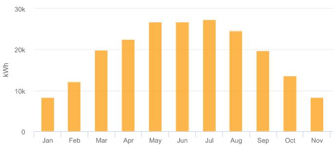
To support the energy needs of the Net Zero building, a renewable energy budget of 25 kBtu/sf/yr was established. This would imply producing about 403,000 kWh/yr through a 366 KW DC rooftop PV system, for a building of roughly 55,000 sf in area.
The design explores different iterations for PV system integration on the roof to meet the net zero ready goal. Refer to the electrical narrative for more information about the studied iterations and the PV system design assumptions.
ROOF TOP PHOTOVOLTAIC (PV) SYSTEM
The Photovoltaic system shall be composed of the following electrical equipment:
Minimum 150kW DC of photovoltaic modules.
Minimum 150kW AC of photovoltaic inverters.
Electricity meters to feed metering data to control system.
The PV system will interconnect to the utility via a line side connection at the main service. A fused disconnect switch will allow for disconnection of the PV rest of the power distribution system and shall act as the utility disconnect as required by DTE.
Contractor is to provide a turnkey system including modules, racking, inverters, panels for a complete operating system.
Contractor to provide commissioning of the system.
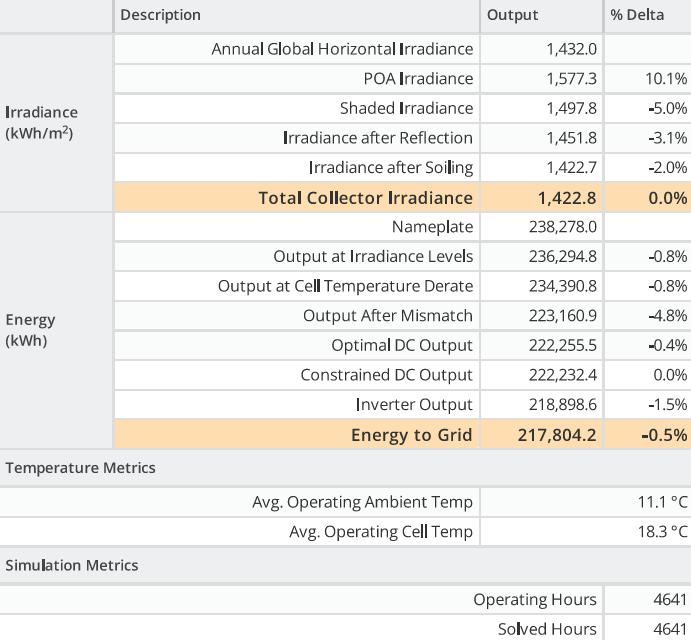
HELIOSCOPE - ANNUAL PRODUCTION REPORT
MODULE DC NAMEPLATE
INVERTER AC NAMEPLATE
HELIOSCOPE - MONTHLY PRODUCTION
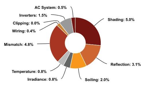
HELIOSCOPE - SOURCES OF SYSTEM LOSS
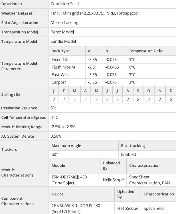
HELIOSCOPE - ANNUAL PRODUCTION HELIOSCOPE - CONDITION SET
- WIRING ZONES
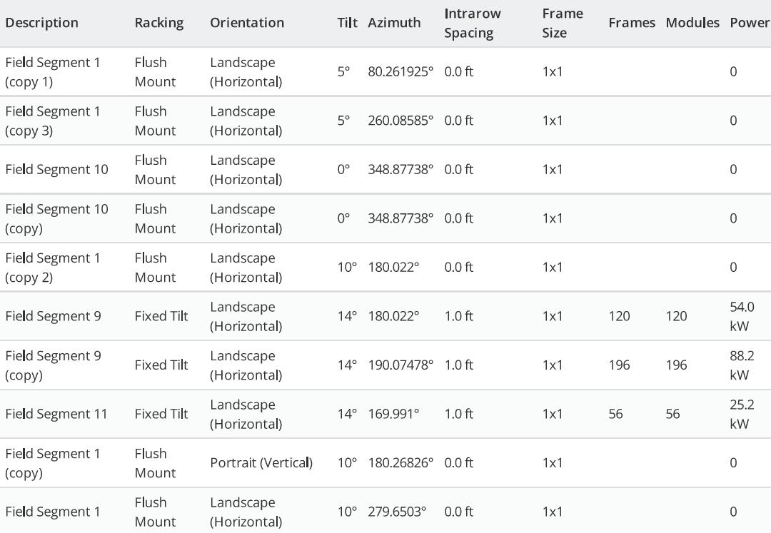
HELIOSCOPE - FIELD SEGMENTS
HELIOSCOPE
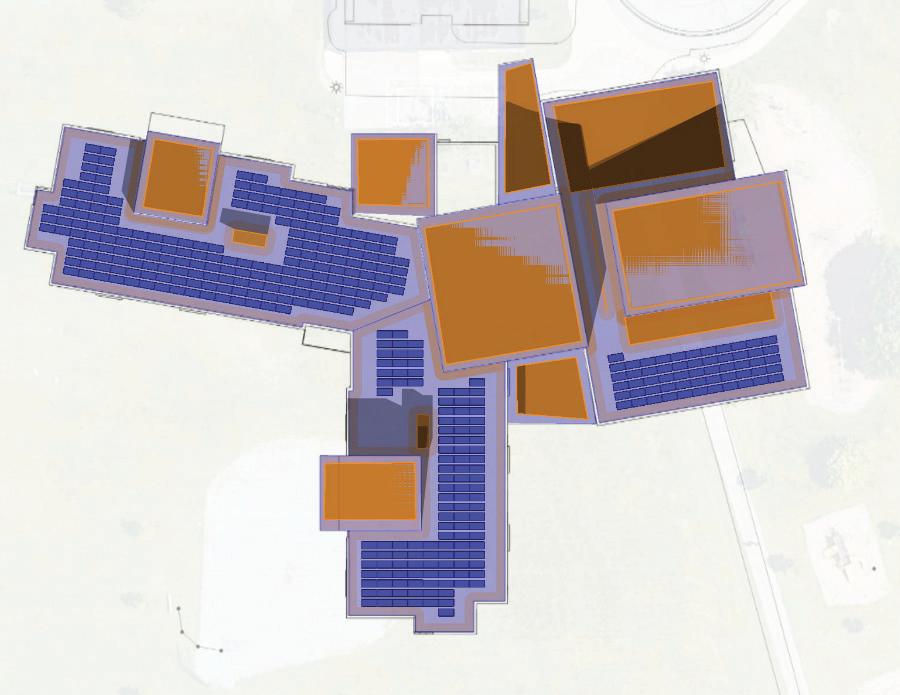
PHOTOVOLTAIC ROOF PLAN
HELIOSCOPE ROOF PLAN AND REPORT SHOWS MAX AMOUNT OF PANELS THAT CAN BE PLACED ON ROOF OF BUILDING. SEE SECTION 3 PLANS AND PROGRAM FOR PLANNED PHOTOVOLTAIC LAYOUT.
Chilled Box Fan Coil System
Decentralized WSHP System
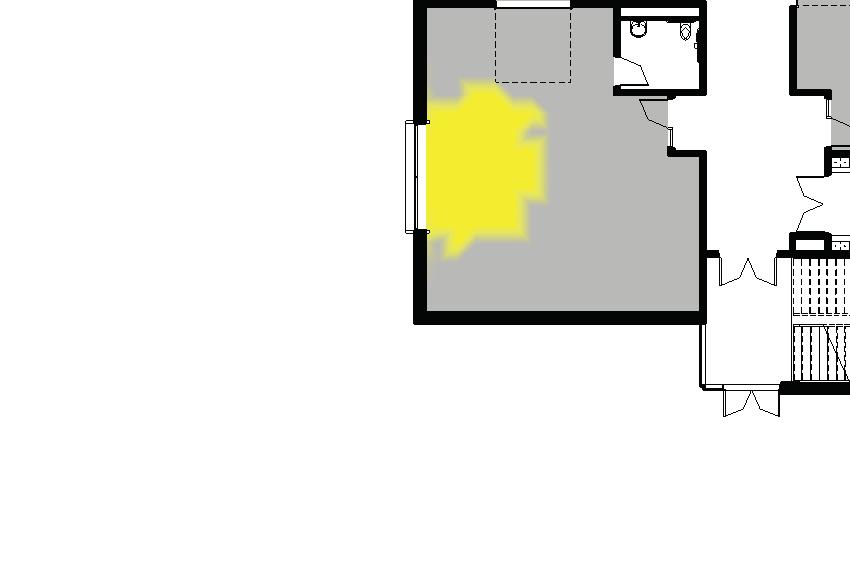
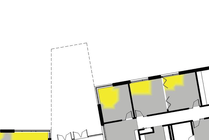
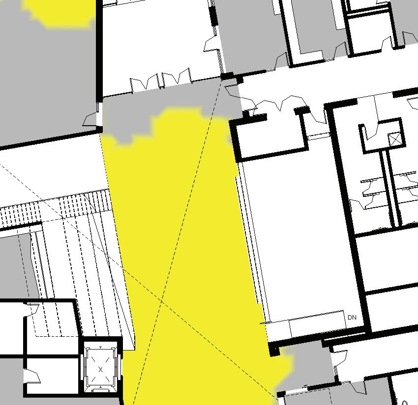
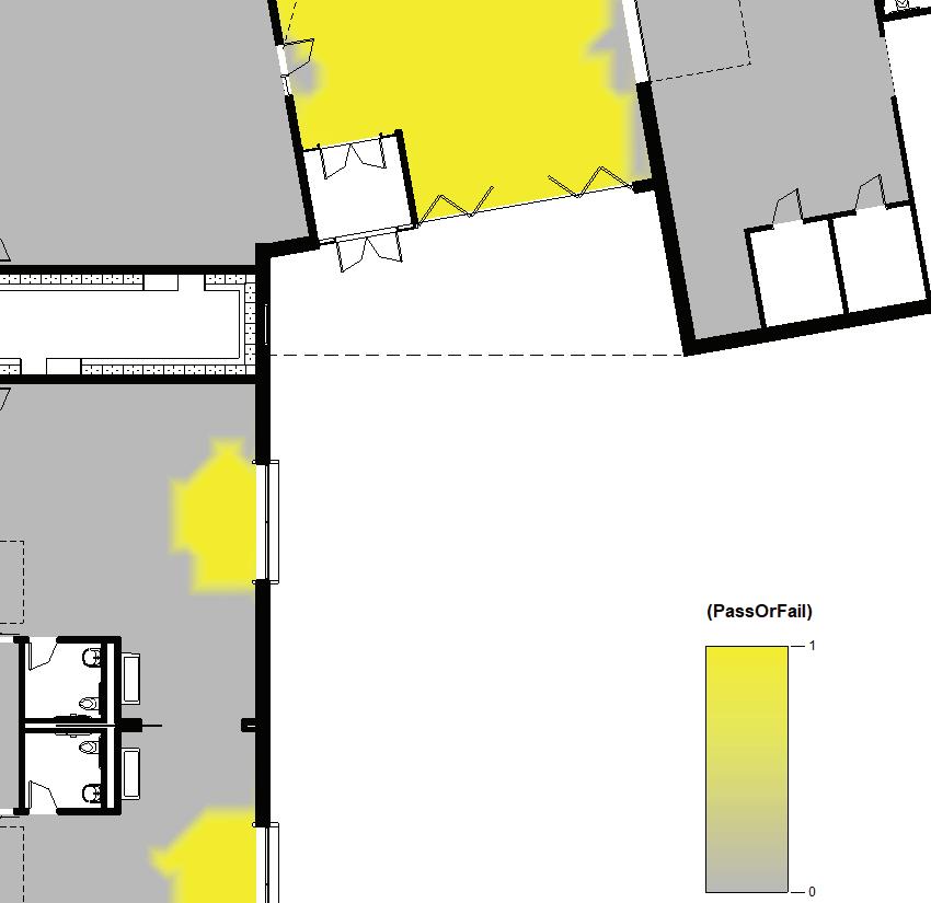
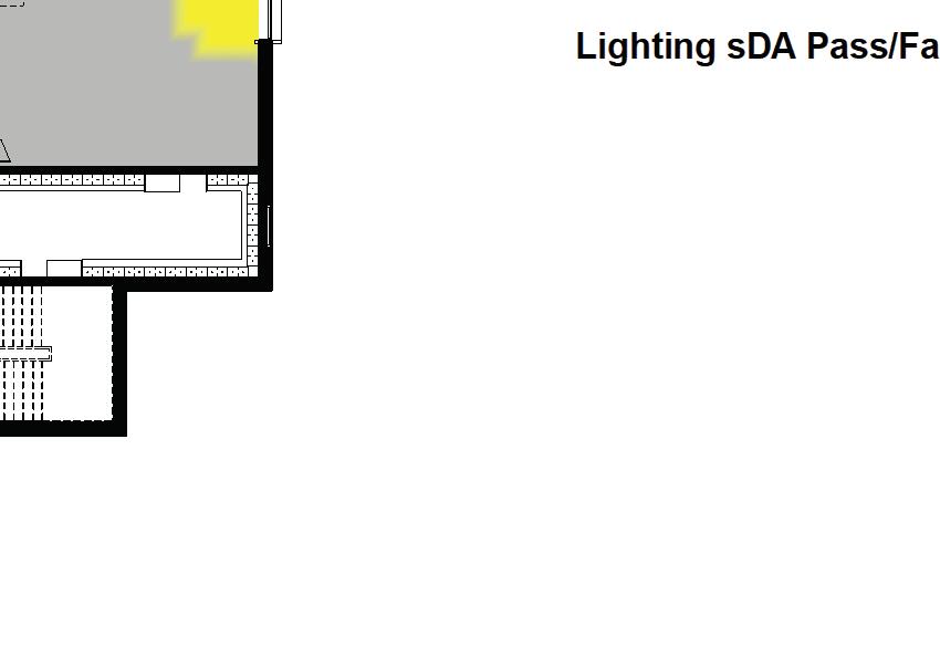
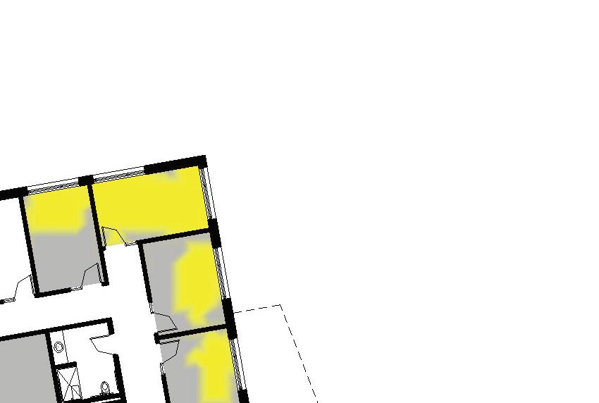
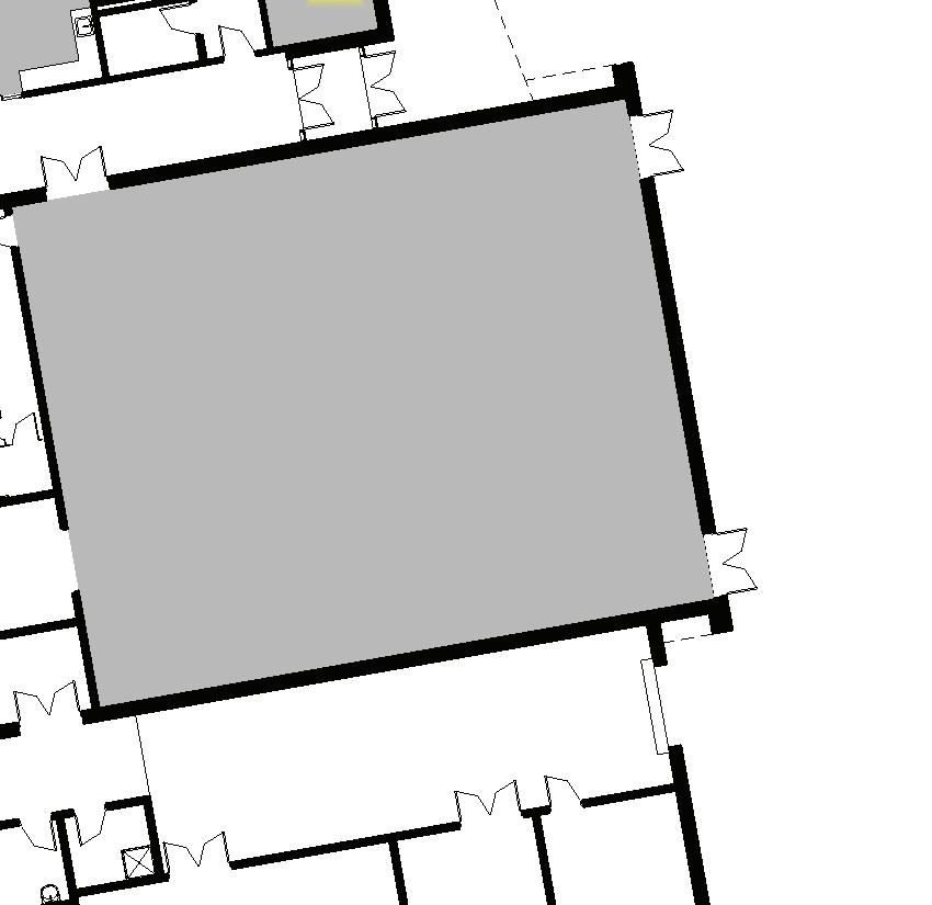
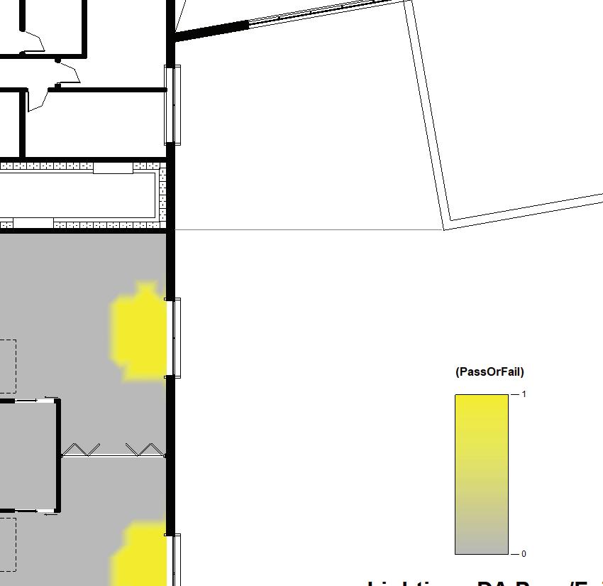
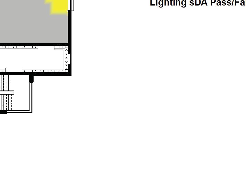
CHPS Insight Lighting Plan - Level 01
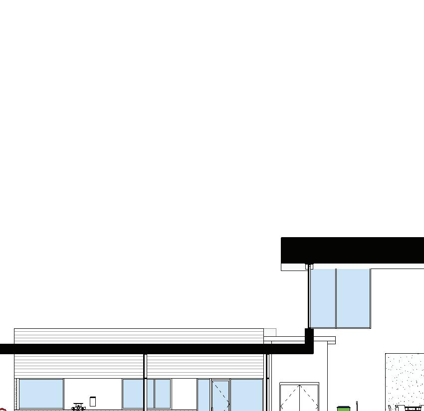
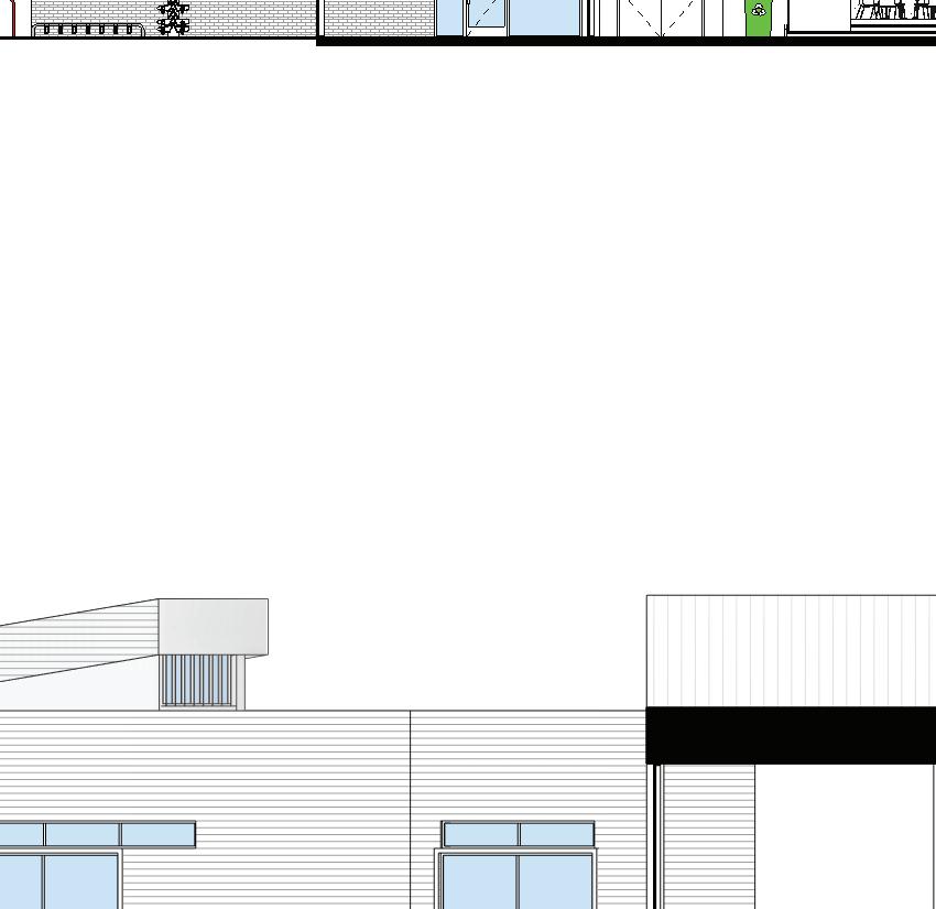
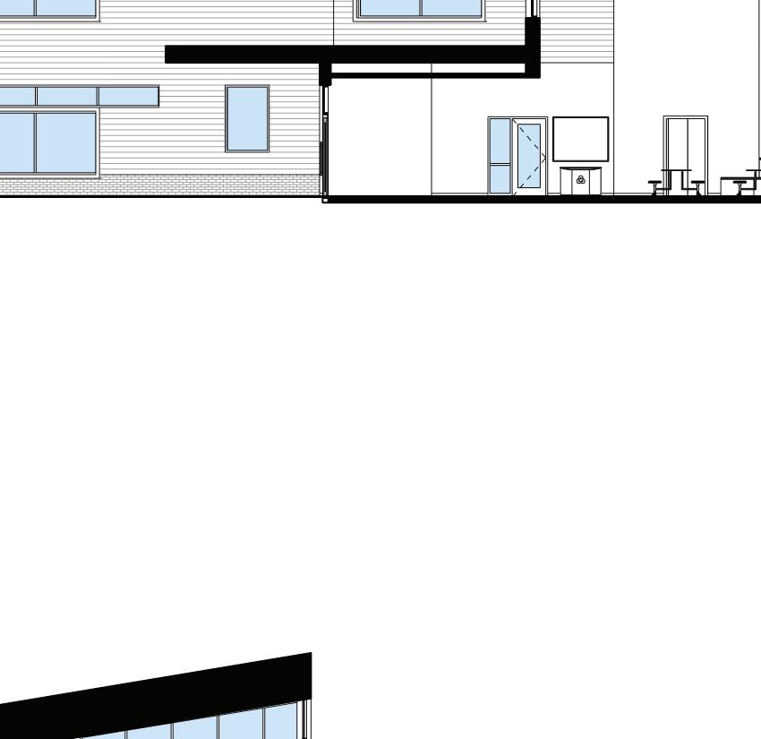
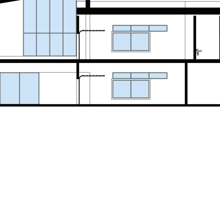
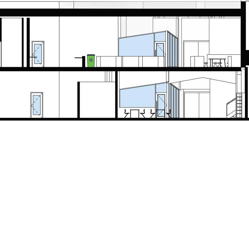
Dicken Elementary School - Section NS-3
Dicken
US-CHPS v2.0 Verified
Project Summary & Status
and provide expected dates of completion. If there are multiple buildings in the project scope, please list them and indicate building type, size, number of classrooms, and student/staff occupancy.
Instructions: Complete the aqua cells under "Project Summary and Status" above and in the "Points Targeted" column below by filling in the blanks or using the drop downs. Columns E-H are for reference regarding submission phase and whether a CHPS worksheet is required. Please use the "Project Team Comments" column to provide CHPS with short notes about your submission not captured elsewhere, and use the "Documentation Reference" column as needed to identify the file name, sheet, or specification section where the required documentation is found (please ensure the documentation within these files is highlighted or otherwise easily found). Use labels such as "DR1", "DR2", "CR1", and "CR2" to indicate which submission the comment or documentation applies to. Prerequisites are highlighted. Subcredits are italicized and can be cumulative, exclusive, or a combination.
Below is an example of how team documentation references should be organized (please delete this when completing the scorecard): DR1:Firstpassteamdesign documentationreference(if applicable).
EQ C2.1.3Electric-Ignitions for Gas Fired Equipment
EQ C2.1.4No Mobile Fossil Fuel Equipment Indoors
EQ C2.1.5Carbon Monoxide (CO)
EQ C2.1.6Electronic
EQ C4.1.1SMACNA
EQ C4.1.2SMACNA
EQ C4.1.3Building
EQ C4.1.4Mold
SS
SS
SS
SS
SS
SS
SS
SS
SS
STRUCTURAL OVERVIEW
A geotechnical report is in progress. The following structural systems were evaluated for their impact on the potential Global Warming Potential (GWP), sometimes referred to as embodied carbon, in Whole Building Life Cycle Analysis (WBLCA).
Mass Timber
Glue-laminated (glulam) beams and columns
Cross-laminated timber (CLT) floor and roof deck
Concrete or gypsum topping at floor
Steel Composite
Steel beams and columns
Steel braced frames
Floor – Composite concrete slab on metal deck
Roof – Steel joists and metal deck
Hybrid A
Steel beams and columns
Steel braced frames
CLT floor and roof decks
Concrete or gypsum topping at floor
Hybrid B
Glulam beams
Steel columns
Steel braced frames
CLT Floor and Roof Decks
PREFERRED OPTION DESCRIPTION
A hybrid steel and timber structural system will be utilized for this building. This system integrates the advantages of steel, a common construction material, with the sustainability of timber contributing to the overall design aesthetic.
The roof system will consist of CLT 3-ply (41/8”/105 mm min) slabs with steel beams supporting the slab.
Glulam beams and/or flitch beams (composite steel/timber members) will be used in lieu of steel beams in certain areas of the building’s roof system.
2nd Floor System
The floor system will consist of CLT 5-ply (5 1/2”/139mm min) slabs with steel beams supporting the slab.
Glulam beams and/or flitch beams (composite steel/timber members) will be used in lieu of steel beams in certain areas of the building’s roof system.
1st Floor System
The floor system will be a 5” concrete slab on ground, f’c = 4,000 psi minimum, with welded wire reinforcement.steel beams in certain areas of the building’s roof system.
Foundation System
As a geotechnical report is still in progress, the following information is preliminary:
The foundations for the proposed school will be formed cast-in-place shallow type foundations with spread footings at columns and continuous strip footings with stem walls at bearing walls. All footings and foundations will be cast-inplace concrete and reinforced with ASTM A615 Grade 60 reinforcing steel. Foundation design will utilize an assumed soil bearing pressure of 3,000 psf minimum.
Lateral System
The lateral system will consist of R=3 steel braced frames.
The structural system supporting exterior stoops will be supported by a 5” slab on void form with shallow perimeter foundations.
FEMA Storm Shelter(as required by code at time of permit)
The roof of the storm shelter will be precast double tees (34” minimum depth) with a 4” concrete topping reinforced with #4 at 12” on center (O.C.).
Alternate for Pricing: 48LH Steel @8’-10’ O.C. with 3.5D Formlock composite steel deck with 2-1/2” concrete (total slab depth = 6”).
The walls of the storm shelter will be a 12” precast sandwich panels (4-4-4 composite panels).
The foundations of the storm shelter will include continuous strip footings.
CODES AND STANDARDS
Design will be per the 2015 Michigan Building Code. This adopts the 2015 International Building Code and the following reference codes:
ASCE 7-10 “Minimum Design Loads for Buildings and Other Structures”
ACI 318-14 “Building Code Requirements for Structural Concrete”
AISC 360-10 “Specification for Structural Steel Buildings”
ACI/MSJC 530-13 “Building Code Requirements for Masonry Structures”
AISI S100-12 “North American Specification for the Design of Cold-formed Steel Structural Members”
Risk Category: III (buildings and other structures, the failure of which could pose a substantial risk to human life)
Dead Loads: Rain Loads: Wind Loads
Roof Superimposed: 35 psf (MEP, ceilings, roofing, deck, solar panels)
Solar Panel Array: 10 psf (accounted for in roof superimposed dead load)
Helical Piles (may be required depending on Geotech report)
Curtain Wall
Metal pan stairs, railings and ladders
Special Inspections
Special inspections will be provided during construction in accordance with Chapter 17 of the Michigan Building Code. The following special inspections will be required:
All concrete (except slabs on grade, sidewalks, and driveways)
Steel construction (load bearing members, shop fabricated assemblies, etc.)
Wood construction (prefabricated wood structural elements and assemblies, etc.)
Welding
Steel detailing (bracing, stiffening, member locations, application of joint details, etc.)
Grading, excavation, and filling
Expansion bolts, screw anchors, and adhesive
anchors
Other inspections as detailed in IBC 2015 ICC 500 Tornado Requirements (structural observations, etc.)
Steel
Wide flange shapes shall conform to ASTM A992 Grade 50.
Channels and angles shall conform to ASTM A36.
Round Hollow Structural Sections (HSS) shall conform to ASTM A500 Grade C (Fy = 46 ksi, Fu = 62 ksi).
Square and Rectangular Hollow Structural Sections (HSS) shall conform to ASTM A500 Grade C (Fy = 50 ksi, Fu = 62 ksi).
Angles and structural plates shall conform to ASTM A36.
High strength bolts shall conform to ASTM F3125, Grade A235N.
Threaded rods shall conform to ASTM A36.
Anchor rods shall conform to ASTM F1554 Grade 55, weldable.
Base plates shall conform to ASTM A36.
Cast-In-Place Concrete
Reinforcing Steel: All reinforcing steel shall conform to ASTM A615, Grade 60 unless noted otherwise on the drawings.
All concrete is normal weight concrete.
Deformed bar anchors shall conform to ASTM A496. (Fy = 70 ksi).
Weldable Reinforcing steel shall conform to ASTM A706.
Headed stud anchors shall conform to ASTM A108. (Fu = 60 ksi).
Foundation walls f’c = 4000 psi, exposure category F2, C1.
Interior slab on grade f’c = 4000 psi, exposure category F0, C0, max. shrinkage 0.035% per ASTM C 157.
Exterior slab on grade f’c = 5000 psi, exposure category F3, W1, C1, air entrained.
Structural Glued-Laminated Timber: Manufactured and identified as required in ANSI/AITC A 190.1 and ASM D3737.
Structural Glued Cross-Laminated Timber: Manufactured and identified in accordance in ANSI/ APA PRG 320.
SPECIFICATIONS - TABLE OF CONTENTS
Maintenance of Cast-In-Place Concrete
Cast-In-Place Concrete
Precast Structural Concrete
Structural Steel Framing
Steel Joist Framing
Steel Decking
Cold-Formed metal Framing
Heavy Timber Construction
Systems Narrative - Mechanical
OVERVIEW
Ann Arbor Public Schools will be building a new 63,000 sq. ft. Dicken Elementary School on the same site as the existing Dicken Elementary School located at 2135 Runnymede Blvd, Ann Arbor, MI 48103. The new elementary school is being designed for 420 students and will be a Verified Leader as certified by the Collaboration for High Performing School (CHPS). The building will have a targeted Energy Use Intensity (EUI) of 25 kBtu/sq. ft/year and be designed to be net zero ready and all-electric ready. The proposed mechanical system for this project will need to be extremely energy efficient to meet these goals and support the overall project goals of being a premier learning environment. With these goals in mind, the project team set out to establish the priorities of the district in addition to the goals outlined above and have proposed a base and alternate mechanical system that meet or exceed the project goals and provide distinct benefits to the district.
The base mechanical system considered would use decentralized, horizontal, Water-Source Heat Pumps (WSHP) to condition the classrooms and admin office areas. The WSHPs would be located and concealed above the corridor ceiling and outside of the classrooms to minimize breakout and radiated noise from the units. These WSHPs would be served by water-source DOAS with VAV Terminal Units to ventilate and dehumidify the spaces. Three (3) SingleZone, Water-Source, VAV Rooftop Units would be provided to independently condition and ventilate the library, commons and gymnasium. The building hydronic system would consist of one (1) pumping system, a condenser water system to serve the compressors located within each of the watersource equipment described above. The building condenser water system would also be directly connected to a geothermal well field via a hydraulic separator to absorb and reject heat from the deep earth and provide conditioning to the building. The geothermal well field is currently assumed to be 50 wells at 500 ft deep and located to the east and south of the building. AAPS has indicated that a geothermal vault is not to be used and a piping manifold shall be located within the mechanical room to serve the geothermal well field.
The alternate mechanical system considered would use FanPowered Box (FPB) Terminal Units with sensible only cooling coils located on the return air inlet to serve the classrooms and admin office areas. These decoupled, sensible only FPBs would be served by Dedicated Outside Air Systems (DOAS) to ventilate and dehumidify the spaces.
The library, student commons and back of house spaces would be served by a Multi-Zone, VAV Rooftop Air Handling Unit (AHU) with VAV Terminal Units serving each of the individual spaces. The Gymnasium would be independently conditioned and ventilated by a Single-Zone, VAV Rooftop AHU. The heating and cooling for all of these devices would be served from the central mechanical room which houses a modular, Heat Recovery Chiller (HRC). The HRC would be capable of providing full heating and cooling during design day periods and able to provide simultaneous heating and cooling during shoulder seasons to reduce energy consumption. The building hydronic system would consist of three (3) separate pumping systems, a heating hot water system, a primary chilled water system and a secondary chilled water system. The primary chilled water system would produce 44°F chilled water and a three-way valve would be used to provide 57°F secondary chilled water to the sensible only cooling devices. Active and passive humidity mitigations strategies would be used to prevent condensation from occurring on secondary chilled water pipes and sensible only cooling coils. Window sensors, pipe condensation sensors and humidity sensors would be used to monitor the humidity in the spaces and adjust the cooling available to spaces or to the entire building to ensure condensation does not occur. The heat recovery chiller would also be connected to a geothermal well field to absorb and reject heat from the deep earth and provide conditioning to the building. The geothermal well field is currently assumed to be 50 wells at 500 feet deep and located to the east and south of the building. AAPS has indicated that a geothermal vault is not to be used and a piping manifold shall be located within the mechanical room to serve the geothermal well field. The design team developed the following documentation to assist the construction manager partner and AAPS in understanding the differences between the systems and to quantify how well each system meets the district’s needs:
Mechanical Systems Schematic Diagrams (located within design book)
Preliminary Geothermal Well Field Layout (located within deign book)
Geothermal Test Bore Formation Thermal
Conductivity Test & Data Analysis (located within appendix of design narrative)
Preliminary Mechanical Room Plans (located within design book)
Preliminary Mechanical Roof Plan (located within design book)
Mechanical Systems Matrix (located within design book)
The mechanical systems matrix will be used to prioritize different factors for the base and alternate systems and quantify how well each system met the needs of the district. This document will ultimately be used to select the preferred mechanical system of the district.
Additionally, the following mechanical systems shall be provided to serve spaces other than the classrooms, admin offices, student commons, library, gymnasium and back of house spaces.
Group and single occupant restrooms shall be served by roof-mounted, downblast, centrifugal exhaust fans and connected via exhaust ductwork and exhaust grilles.
Electrical closets shall be maintained to 10°F above the ambient air temperature with transfer fans that pull adjacent space air through the closet and then transfer it into the ceiling plenum of the corridor.
IT closets and the main electrical room shall be conditioned to 75°F with horizontal, above-ceiling, water-source heat pump fan coil units located in the corridor ceiling plenum. The fan coil unit shall condition the return air plenum air and then be ducted to the IT closet to maintain the necessary space temperature for the IT equipment.
The main mechanical room shall be maintained to 10°F above the ambient air temperature with the use of a roofmounted, downblast, centrifugal exhaust fan to move space air from the adjacent receiving area through the mechanical room.
An emergency ventilation system shall be provided to serve the storm shelter in the event of a tornado that requires the occupants to shelter in place. The emergency ventilation system shall consist of two (2) sidewall, FEMA 361 louvers with motorized dampers, ductwork and an inline exhaust fan to provide ventilation for the emergency design occupancy. The motorized dampers and exhaust fan shall be controlled by a manual switch located in the PE office to operate the system for two (2) hours. All power supporting the emergency ventilation system, including controls, shall be provided from the emergency battery system located within the gymnasium storm shelter.
Natural gas piping shall be extended from the existing underground utility to the north and a meter shall be provided on the exterior of the building near the back of house spaces. The natural gas piping shall be extended to serve the life-safety generator and any gas-fired kitchen cooking equipment. At this time, the emergency power for the 2020 ICC 500 storm shelter is assumed to be provided by batteries located within the storm shelter and natural gas shall not be used for this purpose.
Outdoor Design Conditions
Ann Arbor, MI, USA WMO: 725374
0.4% Cooling DB/MCWB: 89.8°F DB/73.4°F WB
Summer Ambient DB for Air-Cooled Equipment: 105°F
99.6% Heating DB: -2.1 °F DB
0.4% Evaporation WB/MCDB: 76.4°F WB/85.2°F MCDB
Elevation: 839 ft above sea level
Indoor Design Conditions
Spaces with heating, ventilation and air conditioning
- Summer: 75°F DB/50% RH
- Winter: 70°F DB
Mechanical/Electrical Spaces
- Summer: 10°F DB above outdoor ambient temperature
- Winter: 60°F minimum
Acoustical Performance Requirements
Classrooms: 25 NC maximum
Collaboration Spaces: 30 NC maximum
Corridors: 40 NC maximum
Total background noise from the combination of building HVAC systems and exterior noise shall not exceed 35 dBA in core learning spaces and in spaces designated as Inter-Classroom Workspaces and Special Education Rooms.
Total background noise from the combination of building HVAC systems and exterior noise shall not exceed 40 dBA in Performing Arts Spaces and Large Assembly Spaces.
DESIGN CRITERIA
DESIGN CRITERIA, CONT.
Duct Sizing Requirements
Supply & Return in Enclosed Shafts
- Velocity: 2,500 fpm maximum
- Pressure Drop: 0.2” per 100 ft. maximum
Supply and Return Above Ceilings in Corridors
- Velocity: 2,000 fpm maximum
- Pressure Drop: 0.15” per 100 ft. maximum
Supply and Return in Open Ceilings or Above
Ceilings in Classrooms
- Velocity: 1,200 fpm maximum
Pressure Drop: 0.08” per100 ft. maximum
Sizing Requirements
Pipes 2 in and Smaller
- Maximum Pressure Drop: 5 ft. per 100 ft.
Pipes 2-1/2 in and Larger:
- Maximum Velocity: 6 fps
MECHANICAL EQUIPMENT DESCRIPTION
Base System Mechanical Equipment
Central Pump Systems
Basis of Design: Grundfos Hydro MPC
Geothermal Water Pumps
- Pump Quantity: 4 (each pump sized for 33% of flow for N+1 redundancy)
- System Flowrate: 375 gpm
- System Pressure: 80 ft
Condenser Water Pumps
- Pump Quantity: 4 (each pump sized for 33% of flow for N+1 redundancy)
- System Flowrate: 375 gpm
- System Pressure: 80 ft
Packaged, Water-Source, Heat Pump Rooftop Units
Basis of Design: Innovent
Features:
- Energy Recovery Wheels with Bypass
Supply and Return Fan Arrays with - Backdraft Dampers
- Multiple Circuits with Variable Speed Compressors
- Belimo EPIV Control Valves
- Gym & DOAS Units: Hot Gas Reheat
MECHANICAL EQUIPMENT DESCRIPTION, CONT.
Gym WSHP RTU
Supply Airflow: 6,400 cfm
Outside Airflow: 3,200 cfm
Cooling Capacity: 30 tons
Kitchen WSHP RTU
Supply Airflow: 2,000 cfm
Outside Airflow: 750 cfm
Cooling Capacity: 5 tons
Commons WSHP RTU
Supply Airflow: 7,500 cfm
Outside Airflow: 2,500 cfm
Cooling Capacity: 25 tons
Admin WSHP DOAS-1
Supply Airflow: 800 cfm
Cooling Capacity: 5 tons
West Classrooms WSHP DOAS-2
Supply Airflow: 5,500 cfm
Cooling Capacity: 50 tons
South Classrooms WSHP DOAS-3
Supply Airflow: 5,500 cfm
Cooling Capacity: 50 tons
Decentralized Water-Source Heat Pumps
<2 Ton Basis of Design: SmartSource One-Stage Horizontal WSHP
>2 Ton Basis of Design: SmartSource Two-Stage Horizontal WSHP
Classroom Unit Size: 026
Classroom Unit Quantity: 28
Admin Unit Size: 012
Admin Unit Quantity: 6
VAV Terminal Units
Basis of Design: Titus DESV Quantity: 34
Roof-Mounted Exhaust Fans
Basis of Design: Greenheck Model G with VariGreen Motor
Quantity: 7
Inline Transfer Fans
Basis of Design: Greenheck CUE with Vari-Green Motor
Quantity: 4
Horizontal Water-Source heat Pump
Basis of Design: Daikin WaterSource One-Stage WSHP
Unit Size: 012
Quantity: 5
Airflow: 400 cfm
Cooling Capacity: 1 ton
Alternate System Equipment
Heat Recovery Chiller
Basis of Design: Multistack MSH050XNHCIFAA-BDCDC-BAI-CA-B Modules: 4
Cooling Capacity: 176.7 tons
Heating Capacity: 1,370 MBH
Central Pump Systems
Basis of Design: Grundfos Hydro MPC
Geothermal Water Pumps
- Pump Quantity: 4 (each pump sized for 33% of flow for N+1 redundancy)
- System Flowrate: 400 gpm
- System Pressure: 80 ft
Chilled Water Pumps
- Pump Quantity: 3 (each pump sized for 33% of flow for N+1 redundancy)
- System Flowrate: 235 gpm
- System Pressure: 80 ft
Heating Hot Water Pumps
- Pump Quantity: 3 (each pump sized for 33% of flow for N+1 redundancy)
- System Flowrate: 170 gpm
- System Pressure: 60 ft
Gym RTU
- Supply Airflow: 6,400 cfm
- Outside Airflow: 3,200 cfm
Commons RTU
- Supply Airflow: 9,500 cfm
- Outside Airflow: 3,200 cfm
Admin DOAS-1
- Supply Airflow: 800 cfm
West Classrooms DOAS-2
- Supply Airflow: 5,500 cfm
South Classrooms DOAS-3
- Supply Airflow: 5,500 cfm
Reheat Coil
Basis of Design: Titus DLSC Quantity: 34
VAV Terminal Units
- Basis of Design: Titus DESV
- Quantity: 34
VAV Terminal Units with Reheat Coils
- Basis of Design: Titus DESV
- Quantity: 13
Roof-Mounted Exhaust Fans
- Basis of Design: Greenheck Model G with - Vari-Green Motor
- Quantity: 7
Inline Transfer Fans
- Basis of Design: Greenheck CUE with Vari-Green Motor
- Quantity: 4
Rooftop Air Handling Units Horizontal Fan Coil Units with
Basis of Design: Daikin
Features:
Energy Recovery Wheels with Bypass
Supply and Return Fan Arrays with Backdraft Dampers
Gym & DOAS Units: Wrap Around Heat Pipe
Heat Recovery Coil
Belimo EPIV Control Valves
Horizontal Fan Coil Units
- Basis of Design: Titus
- Quantity: 7
- Airflow: 400 cfm
CHPS CONSIDERATIONS
No CFC-based refrigerants shall be used in mechanical systems.
Building shall be all-electric ready.
Indoor Environmental Quality
Integration & Innovation Enery Operations
Filtration media shall a minimum MERV rating of 15. The outdoor airflow shall be no less than 130% of the ASHRAE 62.1 ventilation rates.
The SMACNA guidelines for “Duct Cleanliness for New Construction Guidelines” according to Advanced Levels of Cleanliness
Specify that ductwork be sealed when transported to the construction site.
Store ductwork in clean, dry conditions and keep sealed while it is stored.
Wipe down internal surfaces of ductwork immediately prior to installation to remove dust.
Seal open ends on completed ductwork and overnight work-in-progress.
During installation, protect ductwork waiting to be installed with surface wrapping, etc.
During construction, seal HVAC supply and return openings to protect them from construction dust infiltration (e.g., from drywall installation or wood floor sanding).
The building shall be flushed out with outdoor air to remove indoor pollutants prior to occupancy.
The maximum amount of outdoor air shall be provided continuously for a minimum of 7 days during and after installation of VOC emitting materials
Conduct a flush out of the building for 24 hours a day for 7 days with all supply fans at their maximum rate and position after substantial completion. Temperature shall be maintained at a minimum of 60°F and maximum of 60% humidity. Replace air filter with new filters after flush out and provide two sets of additional replacement filters prior to occupancy.
The mechanical systems shall support the occupied spaces meeting the requirements of ASHRAE Standard 55 for thermal comfort.
Provide an individual temperature control for each classroom with an independent temperature sensor. The isolation between mechanical equipment rooms and core learning spaces, inter-classroom work spaces or special education rooms shall have a STC rating of 60 or greater.
Building shall be net zero ready.
All applicable electrical, mechanical and plumbing systems shall be commissioned by an independent third-party commissioning agent.
Facility staff shall be included in the commissioning O&M training process.
Teachers, administrators and user’s shall be trained to use the lighting and HVAC in the building.
MATERIALS
Metal Ducts
General: Constructed of single-wall galvanized steel with thickness and joining methods to meet the requirements below.
Supply Ducts:
Ducts Connected to Fan Coil Units, Furnaces, Heat Pumps, and Terminal Units:
Pressure Class: Positive 2-inch wg.
Minimum SMACNA Seal Class: C.
SMACNA Leakage Class for Rectangular: 24.
SMACNA Leakage Class for Round and Flat Oval: 12.
Ducts Connected to Variable-Air-Volume AirHandling Units:
Pressure Class: Positive 4-inch wg.
Minimum SMACNA Seal Class: A.
SMACNA Leakage Class for Rectangular: 6.
SMACNA Leakage Class for Round and Flat Oval: 3.
Ducts Connected to Equipment Not Listed Above:
Pressure Class: Positive 3-inch wg.
Minimum SMACNA Seal Class: A.
SMACNA Leakage Class for Rectangular: 12.
SMACNA Leakage Class for Round and Flat Oval: 6
Ducts Connected to Air-Handling Units:
Pressure Class: Positive or negative 3-inch wg.
Minimum SMACNA Seal Class: B.
SMACNA Leakage Class for Rectangular: 12.
SMACNA Leakage Class for Round and Flat Oval: 6.
Ducts Connected to Equipment Not Listed Above
Pressure Class: Positive or negative 3-inch wg.
Minimum SMACNA Seal Class: B.
SMACNA Leakage Class for Rectangular: 12.
SMACNA Leakage Class for Round and Flat Oval: 6.
Outdoor Duct
Outdoor ducts may either be single-wall galvanized steel with weatherproof construction, insulation and pre-fabricated, waterproof membrane made of aluminum top surface bonded to multilayer polyethylene and coated with rubberized asphalt or nonmetal duct specified below.
Ducts Connected to Air-Handling Units
Pressure Class: Positive or negative 3-inch wg.
Minimum SMACNA Seal Class: B.
SMACNA Leakage Class for Rectangular: 12. SMACNA Leakage Class for Round and Flat Oval: 6.
Intermediate Reinforcement:
Galvanized-Steel Ducts: Galvanized steel or carbon steel coated with zinc-chromate primer.
Elbow Configuration:
Rectangular Duct: Comply with SMACNA’s “HVAC Duct Construction Standards – Metal and Flexible,” Figure 4-2, “Rectangular Elbows.”
Velocity 1000 fpm or Lower:
Radius Type RE 1 with minimum 0.5 radius-to-diameter ratio.
Mitered Type RE 4 without vanes.
Velocity 1000 to 1500 fpm:
Return Ducts
Ducts Connected to Fan Coil Units, Furnaces, Heat Pumps, and Terminal Units:
Pressure Class: Positive or negative 2-inch wg.
Minimum SMACNA Seal Class: C.
SMACNA Leakage Class for Rectangular: 24.
SMACNA Leakage Class for Round and Flat Oval: 12.
Radius Type RE 1 with minimum 1.0 radius-to-diameter ratio.
Radius Type RE 3 with minimum 0.5 radius-to-diameter ratio and two vanes. Mitered Type RE 2 with vanes complying with SMACNA’s “HVAC Duct Construction Standards – Metal and Flexible,” Figure 4-3, “Vanes and Vane Runners,” and Figure 4-4, “Vane Support in Elbows.”
Velocity 1500 fpm or Higher:
Radius Type RE 1 with minimum 1.5 radius-to-diameter ratio.
Radius Type RE 3 with minimum 1.0 radius-to-diameter ratio and two vanes.
Mitered Type RE 2 with vanes complying with SMACNA’s “HVAC Duct Construction Standards – Metal and Flexible,” Figure 4-3, “Vanes and Vane Runners,” and Figure 4-4, “Vane Support in Elbows.”
Round Duct: Comply with SMACNA’s “HVAC Duct Construction Standards
Metal and Flexible,” Figure 3-4, “Round Duct Elbows.”
Minimum Radius-to-Diameter Ratio and Elbow Segments: Comply with SMACNA’s “HVAC Duct Construction Standards – Metal and Flexible,” Table 3-1, “Mitered Elbows.” Elbows with less than 90-degree change of direction have proportionately fewer segments.
Round Elbows, 12 Inches and Smaller in Diameter: Stamped or pleated. Round Elbows, 14 Inches and Larger in Diameter: Standing seam.
Branch Configuration
Rectangular Duct: Comply with SMACNA’s “HVAC Duct Construction Standards – Metal and Flexible,” Figure 4-6, “Branch Connection.” Round: Comply with SMACNA’s “HVAC Duct Construction Standards – Metal and Flexible,” Figure 3-5, “90 Degree Tees and Laterals,” and Figure 3-6, “Conical Tees.” Saddle taps are permitted in existing duct.
Rectangular Main to Rectangular Branch: 45-degree entry.
Rectangular Main to Round Branch: Spin in.
Velocity 1000 fpm or Lower: 90-degree tap.
Velocity 1000 to 1500 fpm: Conical tap.
Velocity 1500 fpm or Higher: 45-degree lateral.
Nonmetal Ducts
Outdoor Duct and Fittings: Concealed, Supply-Air Duct and Plenum Insulation:
Phenolic-Foam Rectangular Ducts and Fittings:
Minimum Panel Thickness: 1-3/32 inches.
Aluminum Cladding: Minimum 0.032 inch thick.
Polymeric Sealing System: Coat ducts, including gang-nail couplings, grip flanges, and couplings.
Fabric: Woven permeable polyester.
Shape: Round.
Air-Outlet Configuration: Permeable fabric.
Duct Connection Type: Round zipper.
Internal Retention System:
Air diffusers shall be constructed with internal retention system.
System shall consist of an internal 360 degree hoop system, spaced 5’ on center.
System shall be installed with a one row suspension system located 1.5” above top-dead-center of the textile system.
System attachment to cable or U-Track shall be made using Gliders spaced 12 inches.
U-Track suspension hardware to include 8’ sections of aluminum track, aluminum splice connectors, track endcaps and vertical cable support kits – consisting of a length of cable with cable connectors. Radius aluminum track must be included for all horizontal/flat radius sections. Galvanized steel cable
Support lengths available in 5’(standard), 10’, 15’, & 30’
Accessories
Quick-connect joint.
Fabric tensioning system for both the entire length and circumference of fabric duct.
Snap hooks. End cap.
Removable support hoops.
Duct Insulation Piping
Mineral-fiber blanket, 1-1/2 inches thick and 0.75lb/cu. Ft. nominal density.
Condenser Water, Heating Hot Water, Primary Chilled Water and Secondary Chilled Water Systems Piping, Aboveground:
NPS 2 and smaller: Type L, drawntemper copper tubing, wrought-copper fittings, and soldered joints.
NPS 2-1/2 and larger: Shall be one of the following:
Schedule 40 steel pipe; Class 150, malleable-iron fittings; castiron flanges and flange fittings; and threaded joints
Schedule 40 steel pipe; Class 150; grooved, mechanical joint coupling and fittings; and grooved, mechanical joints.
Horizontal Ground-Loop Heat-Pump Piping, belowground: High density polyethylene pipe, type PE4710, with minimum ASTM D3350 cell classification of PE445576C.
Vertical Ground-Loop Heat-Pump Piping, belowground: High density polyethylene pipe, type PE4710, with minimum ASTM D3350 cell classification of PE445576C with minimum working pressure rating of 200 psi DR 11.
Makeup-water piping: Type L, drawn-temper copper tubing, wrought-copper fittings, and soldered joints.
Condensate-Drain Piping: Type M, drawn-temper copper tubing, wrought-copper fittings, and soldered joints.
Blowdown-Drain Piping: Same materials and joining methods as for piping specified for the service in which blowdown drain is installed.
Inlet: Same as service where installed with metal-to-plastic transition fittings for plastic piping systems according to piping manufacturer’s written instructions.
Outlet: Type K, annealed-temper copper tubing with soldered or flared joints.
Safety-Valve-Inlet and -Outlet Piping for Hot-Water Piping: Same materials and joining methods as for piping specified for the service in which safety valve is installed with metal-to-plastic transition fittings for plastic piping systems according to piping manufacturer’s written instructions. Refrigerant piping:
Exposed in finished areas: Type L, drawn-temper tubing and wroughtcopper fittings, and soldered joints. Concealed or exposed in unfinished areas: Type L, annealed- or drawntemper tubing and wrought-copper fittings, and soldered joints.
Natural gas piping:
Low pressure, indoor, NPS 2 and smaller: Schedule 40 steel pipe, Class 150, malleable-iron fittings and threaded joints.
Low pressure, indoor, NPS 2-1/2 and smaller: Schedule 40 steel pipe, Class 150, wrought-steel fittings and welded joints.
Low pressure, outdoor, NPS 2 and smaller: Schedule 40 steel pipe, Class 150, malleable-iron fittings and threaded joints.
Low pressure, outdoor, NPS 2-1/2 and smaller: Schedule 40 steel pipe, Class 150, wrought-steel fittings and welded joints.
Install dielectric fittings in piping at connections of dissimilar metal piping and tubing with isolation valves upstream and downstream of the fitting.
Plastic piping will not be acceptable for any use on the project.
Pipe NPS 2 and Smaller: Bronze globe valves, Class 150, with bronze disc, and with soldered or threaded ends.
Pipe NPS 2-1/2 and Larger: Iron globe valves, Class 250, with flanged ends.
Hydronic Systems Valve Schedule
Pipe NPS 2 and Smaller: Bronze ball valves, two piece, with stainless-steel trim, and full port. Valves may be provided with solder-joint ends instead of threaded ends.
Gas Valve Schedule
Pipe NPS 2 and Smaller: Bronze ball valves, two piece, with bronze trim, and full port.
Hydronic Systems Valve Schedule
Pipe NPS 2-1/2 and Larger: Iron, Single-Flange Butterfly Valves, NPS 2-1/2 to NPS 12: Ductile-iron disc, 200 CWP, and EPDM seat.
Hydronic Systems Valve Schedule
Pipe NPS 2 and Smaller: Bronze Valves: May be provided with solder-joint ends instead of threaded ends.
Bronze swing check valves with bronze disc, Class 150.
Hydronic Systems Valve Schedule NPS 2-1/2 to NPS 12: Iron swing check valves with lever and spring closure control, Class 125.
Pipe NPS 2-1/2 and Larger: Iron Valves, NPS 2-1/2 to NPS 4: May be provided with threaded ends instead of flanged ends.
Natural Gas Valve Schedule
Line Pressure Regulators: Single stage, cast iron body with zincplated steel trim, nitrile rubber seat, interchangeable aluminum orifice, with factory mounted overpressure protection devices, with maximum inlet pressure rated of 5 PSIG.
Appliance Pressure Regulator:
Single stage, Die-cast aluminum body with zinc plated steel trim, nitrile rubber seat, with maximum inlet pressure rating of 5 PSIG.
Valves
Globe Valves
Ball Valves
Butterfly Valves
Check Valves
Pressure Regulating Valves
Fabric Air-Distribution Devices
MATERIALS, CONT.
Pressure Regulating Valves
Natural Gas Valve Schedule
Line Pressure Regulators: Single stage, cast iron body with zincplated steel trim, nitrile rubber seat, interchangeable aluminum orifice, with factory mounted overpressure protection devices, with maximum inlet pressure rated of 5 PSIG.
Appliance Pressure Regulator: Single stage, Die-cast aluminum body with zinc plated steel trim, nitrile rubber seat, with maximum inlet pressure rating of 5 PSIG.
Piping Insulation
Indoor Piping Insulation Schedule
Heating Hot Water Supply and Return, Greater than 105°F and Less than 140°F: Mineral-Fiber, Preformed Pipe Insulation, Type I, 1.5 inches thick.
Primary and Secondary Chilled Water Supply and Return, Greater than 40°F and Less than 60°F: Mineral-Fiber, Preformed Pipe Insulation, Type I, 1.0 inch thick. Condenser Water Supply and Return: Mineral-Fiber, Preformed Pipe Insulation, Type I, 1.0 inch thick.
Refrigerant: flexible elastomeric: 1 thick
Loose-Fill Insulation for Horizontal, Ground-Loop Heat-Pump Piping, Belowgrade:
Granular, Loose-Fill Insulation:
Inorganic, nontoxic, nonflammable, sodium potassium aluminum silicate with calcium carbonate filler. Include chemical treatment that renders insulation hydrophobic.
Source Limitations: Obtain insulation from single source from single manufacturer.
Thermal Conductivity (k-Value): 0.60 at 175 deg F and 0.65 at 300 deg F.
Systems Narrative - Mechanical
TEMPERATURE CONTROLS
Application Temperature Range: 35 to 800 deg F.
Dry Density: 40 to 42 lb/cu. Ft..
Strength: 12,000 lb/sq. ft..
Insulation at Pipe Joints and Fittings: Provide pipe system manufacturer’s recommended joint and fitting seals, with formed, spray, or loosefill insulation. Provide pipe system manufacturer’s recommended sealants and adhesives required to form watertight boundaries at outer conduit.
Condensate Drain, flexible elastomeric: ¾ inch thick
Geothermal Well Field Borehole Backfill
Grouting shall conform to State Rules.
Grout Base: Processed bentonite selected and milled specifically for grouting of vertical ground loop heat exchangers.
Grout Aggregate: Sand, screened to between 40 to 70 mesh, 99% or higher silica content. PowerTEC graphite as provided by GeoPro Inc., is an acceptable alternative to sand aggregate.
Grout Mixture Properties:
Ratio: One part bentonite to five parts sand to approximately three parts water (by weight).
Graphite may be substituted for sand and mixed at a ratio that will provide equivalent or higher thermal conductivity specified.
Thermal Conductivity: Minimum of 1.0 Btu/hr-ft °F, as determined when tested in accordance to ASTM D-5334.
Density: not less than 10 lb/gal.
Active Solids: not less than 20% (Bentonite’s ratio to Water(by weight)).
Permeability: Less than 1.0 x 10⁻⁷ cm/sec when tested in accordance to ASTM D-5084.
All new temperature controls shall be electronic, Direct Digital Controls (DDC) and integrated into the new Tridium Niagara Building Automation System (BAS). Additionally, the Dicken Elementary School BAS shall be integrated into the AAPS campus wide front end software.
To allow for future integration into the Tridium Niagara BAS, all new direct digital controls (DDC) shall be based on the Tridium Niagara 4 Framework (or “Niagara”). All aspects of the system shall be provided using open protocol and open automation infrastructure that integrates diverse systems and devices (regardless of manufacturer, communication standard or software) into a unified platform that can be easily managed in real time over the Internet using a standard Web browser.
The control system shall consist of sensors, indicators, actuators, final control elements, interface equipment, other apparatus, accessories, and software connected to distributed controllers operating in multiuser, multitasking environment on token-passing network and programmed to control mechanical systems.
Each piece of new equipment shall be integrated to and each alarm that is sent shall be individually mapped and displayed at the BAS. This shall include at a minimum but not limited to: air handling equipment, water-source equipment, pumps, terminal units, mixing valves, and variable frequency drives.
All NACs shall have Niagara Compatibility Statements (NICS) as listed below:
PROPERTY VALUE
STATION COMPATIBILITY ALL STATION COMPATIBILITY ALL TOOL COMPATIBILITY IN ALL TOOL COMPATIBILITY OUT ALL
Systems Narrative - Electrical
OVERVIEW
This report is intended to present electrical systems data applicable for new construction. It is not intended to provide a detailed description of the new electrical systems, nor to encompass all of the work required to construct the new facilities according to any proposed plan. The following is a limited narrative of directives to help develop system design.
The electrical systems involved in the design of this facility include power distribution, lighting, fire alarm, telephone, intercom, data cabling. Design criteria places emphasis on the following:
Systems efficiency and functionality
Sustainability
Economy to the owner
CODES AND STANDARDS
All electrical systems for this facility will be designed in accordance with all applicable codes and standards. The applicable codes and standards include, but are not limited to, the following:
International Building Code
National Electrical Code – 2021
Illuminating Engineering society of North America Handbook, 10th Ed.
NFPA
LEED-NC
LIGHTING SYSTEMS AND CONTROLS
Design Criteria
Typical lighting shall be LED with 0-10V dimming. Automatic controls (vacancy/occupancy sensors and daylighting controls) shall be used throughout the facility, except in areas such as electrical and mechanical rooms where false operation could create a safety hazard. In areas where appropriate. All interior light sources shall have a color rendering index of 80 or higher and have a color temperature between 3500-4000K. A significant daylight contribution is anticipated throughout space and as a result, daylight harvesting technologies shall be utilized extensively.
Lighting control shall be distributed with networkable devices.
LIGHTING SYSTEMS AND CONTROLS, CONT.
Emergency lighting: Assembly areas, egress paths, labs, conference rooms, and windowless classrooms will have emergency lighting.
Night lights: Assembly areas, egress paths, labs, conference rooms, and windowless classrooms will have night lighting.
Interior Lighting Intent by Space Type
Linear pendant up/down LED with 0-10V dimming and 40 fc average. Focal Point Seem series or equal.
Lighting control scheme consisting of wall control station, vacancy sensors, and photocells, where applicable per applicable energy codes. Wall station will consist of on/off, dimming for all zones.
Cylinder LED with 0-10V dimming and 40 fc average.
Focal Point FLC series or equal.
Lighting control scheme consisting of wall control station, dual technology vacancy sensors, and photocells, where applicable per applicable energy codes. Wall station will consist of on/off, dimming for all zones.
Linear wall mounted up/down LED, 0-10V dimming and RGB color tuning. SPI AIC series or equal.
Lighting control scheme consisting of wall control station, vacancy sensors, and photocells, where applicable per applicable energy codes. Wall station will consist of on/off, dimming for all zones.
Linear pendant LED - with 0-10V dimming and 40 fc average. Focal Point Seem series or equal.
Selected fixtures, approximately 48’ on center, shall be connected to a night lighting circuit.
Exit lights shall be white face, red letters, LED type per energy code guidelines. Exit lights shall be connected to the emergency generator.
Lighting control by ceiling mounted occupancy sensors and the building automation system. Lights on occupancy sensor, manual switches will not be provided.
Daylight harvesting will be provided in selected areas of the corridor system where appropriate.
Pendant cylinder LED. Focal Point FLC series or equal. Two to three large scale decorative fixture. BOD - SPI Lighting Novato Line + Arcs series or equal.
All with 0-10V dimming and combined 40 fc average. Occupancy sensors and wall stations shall be utilized. The occupancy sensors shall reduce the overall lighting level to a minimum state when the space is unoccupied. The wall station will provide override functions.
Multiple zones of daylight harvesting will be provided.
A combination of linear pendant direct/indirect, cylinder and decorative fixture all with 0-10V dimming and combined 40 fc average.
Task lighting may also be provided at any tables used for reading.
Lighting controls will consist of dual technology occupancy sensors and wall stations with preset scenes.
Linear recessed LED with 0-10V dimming and 40 fc average. Focal Point Seem series or equal.
The lighting control of these rooms shall be a combination wall station and an vacancy sensor.
Wall sconce in mother’s room (BOD Luceplan D85 series or equal).
Linear pendant LED with 0-10V dimming and 40 fc average.
The lighting control of these rooms shall be a combination wall station and an vacancy sensor.
Cylinder LED
Decorative fixture over furniture (BOD Roll & Hill – Half and Half series or equal)
All fixtures 0-10V dimming and 40 fc average.
The lighting control of these rooms shall be a combination wall station and an vacancy sensor.
Storage Rooms
Storage areas shall have 4’ LED industrial surface mounted directly to structure or pendant mounted with chain.
Lighting control of these rooms shall be accomplished with a ceiling mounted vacancy sensor with on/off low voltage switch on wall.
Public Toilet Rooms
Lighting will consist of LED slot fixtures along the perimeter of the room with downlights.
Lighting controls will be ceiling mounted occupancy sensors. Manual switches will not be provided.
Lighting will consist of 1’ x 4’ LED.
Lighting controls will be ceiling mounted occupancy sensors. Manual switches will not be provided.
The kitchen area shall have 2’ x 4’ LED flat lens, NSF rated.
Lighting control of the kitchen shall be accomplished with local switches.
Mechanical/Electrical Rooms
Mechanical and Electrical Areas shall have 4’ LED industrial; surface mounted directly to structure or pendant mounted with chain.
Lighting control will consist of local switches only. Occupancy sensors will not be used do to safety concerns with live or moving parts.
Gym/Multi-Purpose
Small Toilet Rooms Kitchen Nurses
The gym shall have Linear industrial direct/indirect LED fixture with 0-10V dimming and wire-guard. 40 fc average.
Lighting control shall be from a Gym Control Panel. Multiple control zones will be implemented for flexible use of the space via LV controls. Ceiling mounted high-bay occupancy sensors will be located throughout.
Linear recessed LED with 0-10V dimming and 40 fc average.
Lights located over beds.
The lighting control of these rooms shall be a combination wall station and an vacancy sensor.
Interior Lighting Intent by Space Type, cont.
Projects/STEM Collab
Combination of linear pendant LED direct/indirect, 0-10V dimming and recessed fixtures will be used. Task lighting may also be provided at any tables used for reading.
Lighting controls will consist of occupancy sensors and wall stations. Daylight harvesting will also be implemented. Multiple zones of daylight harvesting will be provided. The multiple zones would allow additional light fixtures to be turned off as the light level increases in the area.
Small/Medium Group
Large decorative pendant LED with 0-10V dimming and 40 fc average. OCL Loop series/ LightArt Empire Shade series or equal.
Lighting control scheme consisting of wall control station, vacancy sensors, and photocells, where applicable per applicable energy codes. Wall station will consist of on/off, dimming for all zones.
Coat Room
Recessed downlight LED with 0-10V dimming and 40 fc average.
Lighting control scheme consisting of wall control station, vacancy sensors, and photocells, where applicable per applicable energy codes. Wall station will consist of on/off, dimming for all zones.
Stairs
LED spaced 0-10V dimming and 20 fc average. Dim to 30% during unoccupied periods.
EXTERIOR LIGHTING
Design Criteria
All exterior light fixtures will be full cutoff, except for special use, such as the flag fixtures (if required).
Building Perimeter:
Building Perimeter shall be lit with LED fixtures, mounted on 15’ poles, or building mounted, located as required to achieve minimum required foot-candles on walkways.
LED downlights shall be utilized in canopies. LED wallpacks shall be utilized for building mounted lighting.
Architectural features, flag poles and signage shall be illuminated with floodlights, or wall mounted fixtures.
Exterior lighting control shall be accomplished by a building automation system in conjunction with a photocell. The exterior lighting shall be zoned so areas can remain illuminated dusk to dawn or be scheduled to turn off at a specified time.
Parking / Roadway:
Roadways and parking lots shall be lit with LED pole mounted fixtures. The pole height shall be 30’ with spacing of approximately 90-100’.
Control shall be the building automation system in conjunction with a photocell and occupancy sensor.
BASIC ELECTRICAL MATERIALS AND METHODS
Emphasis in equipment and systems selection will be placed on manufacturers readily available to and serviceable from the Wahpeton area. Equipment used will be manufacturer’s standard where possible. Major equipment and systems product submittal review copies will be provided to the owner during the procurement stages.
Power Distribution & Wiring
Design Criteria
Main Service: The new electrical service voltage will be 277/480 volts. At 480, the new service size will be approximately 2000 amps. The main circuit breaker will require GFI protection.
Lighting circuits shall be 277V.
480V 3 phase circuits will be used for large motors, pumps, kitchen equipment, plumbing, HVAC, etc.
Main Switchgear: The main gear will be circuit breaker type, located in the main electrical room.
Surge protection will be provided. It is anticipated that the service shall be fed from a utility owned pad mounted transformer.
Power Distribution & Wiring Cont.
Panelboards
Panelboards shall be circuit breaker type and located within dedicated electrical rooms (except in the kitchen, where a flush mounted panel will be located). Some panels may also be located in mechanical rooms.
Panelboards serving computer loads shall have TVSS units installed to prevent electrical surges that can damage computer equipment.
Electrical feeders to panels serving computer areas shall have oversized neutral conductors to prevent overheating due to harmonics from computer loads.
Transformers shall feed all 208V panels.
Transformers shall be located in dedicated electrical rooms, wall or floor mounted as space allows.
Natural gas generator with separate transfer switches for emergency, optional and fire pump.
Fire Pump, if required.
EM Lighting
Exit Signs
Low Voltage Loads
BMS
Access control IT Racks
EM convenience receptacles throughout (red)
Fire Alarm system
Sump Pumps
Shelter
Storm shelter powered by battery inverter
EM Lighting
Exit Signs
Ventilation
Loads
Combination starter/disconnect provided by Division 26.
Variable Frequency Drives supplied by Division 23, installed by Division 26.
Typical motor voltages:
½ hp and less: 120V or 208V single phase ¾ hp and greater: 480V three phase.
Power Distribution & Wiring Cont.
Rough-in for other trades
Temperature control, CO and humidistat sensor rough in by Division 26.
Technology, security, other low-voltage rough-in by Div. 26.
Wiring Devices
Receptacles:
Heavy Duty commercial grade.
Device color: gray
Switches, typical:
120/277, 20A.
Device color: gray
Faceplates:
Finish: stainless steel
Multi-service floor boxes: avoid floor boxes except for computer rooms or areas approved by owner.
Dual service, recessed activation.
Power, data, and phone communications present where necessary.
Walker RFB or equivalent.
Exterior Receptacles:
Exterior receptacles will be placed by exits.
All exterior receptacles will have weather-proof while in use covers and mounted at 24” above grade. They will also be GFI type.
Power Poles:
Dual service.
Power, data, and phone communications present where necessary.
Wiremold/Legrand or equivalent.
Generator
Storm
Motor
DESIGN CRITERIA
System shall be an addressable system. Smoke detection will be located where required by code. Alarm notification devices will be located throughout the building. Strobe lights will be located in corridors, classrooms, conference rooms, bathrooms, and other public areas. Horns will be located as necessary to achieve required sound levels.
Manual pull stations shall be located at all the building engineer’s office, main mechanical room and main administrative offices. Manual pull stations shall also be provided at the lower level parking ramp.
Smoke Detectors shall be located as follows:
In corridors no more than 30’ on center, no more than 15’ from corridor ends.
Storage rooms
Maintenance and mechanical equipment rooms mezzanines
Heat Detectors shall be located as follows:
Kitchen, boiler room, and main electrical room.
Duct Detectors shall be located as follows:
Per NFPA guidelines, in supply and return ductwork for air handling units over 2,000 CFM.
Remote indicator lights will be provided in a visible location for the duct smoke detectors.
Horn/Strobes shall be located as follows:
Position ADA 15 candela horn/strobe combination units in corridors, spaced no more than 100’ on center.
Large assembly rooms: gymnasium, media center, etc., not to exceed 100’ on center.
Areas with high ambient noise levels: machine rooms, music.
Exterior of building: locate in areas of outdoor assembly; weather-proof.
Mini-horn strobes (30 or 75 candela) in classrooms.
Strobes; due to ADA requirements, strobe units are required in the following areas:
Public toilets.
Each classroom
Public accessible conference rooms.
Assembly spaces shall have voice evacuation speakers. Strobes will also be provided in these spaces. The system shall be capable of playing both live and pre-recorded voice announcements.
Interface fire alarm control panel’s alarm output with an auto dialer to notify responsible party(s).
COMMUNICATIONS SYSTEMS
Design Criteria
Clock/PA System
An IP Clock/PA unit will be provided by the owner and installed by the contractor. Located in instructional and common spaces.
Telephone system
A telephone unit will be provided by the owner and installed by this contractor. Cabling shall be CAT6a. Located in instructional, office, conference, and common spaces.
OVERVIEW
Ann Arbor Public Schools will be building a new 63,000 sq. ft. Dicken Elementary School on the same site as the existing Dicken Elementary School located at 2135 Runnymede Blvd, Ann Arbor, MI 48103. The new elementary school is being designed for 400 students and will be a Verified Leader as certified by the Collaboration for High Performing School (CHPS). The district is prioritizing providing the highest quality water possible, reducing water usage and reducing energy used to generate domestic hot water. The proposed plumbing systems and equipment are intended to meet and exceed the district’s goals.
The incoming domestic water utility to the new Dicken Elementary School shall be extended from the existing domestic water utility serving the existing building on the north portion of the site. The Civil Schematic Design documents show the extension of the existing utility to within 5 ft of the new building. The domestic water utility shall enter into the incoming water service utility room in the back of house area below grade as a combined 6” domestic water and fire protection utility. The 6” incoming utility shall then split into a 4” domestic water service and 6” fire protection service above grade. The 4” domestic water utility shall then split again into a 2” lawn irrigation system and 3” domestic water system. Each of the two systems shall have a Reduced Pressure Backflow Preventer to protect the domestic water utility and Water Meter to meter the water consumption. The Lawn Irrigation System shall then be extended below grade and to the exterior of the building. An irrigation system booster pump shall be provided by the landscape architecture design to serve the irrigation system. A domestic water booster pump system shall be provided after the water meter and backflow preventer within the main mechanical room to increase the pressure as required to meet the 30 PSIG minimum pressure requirement at the furthest flush fixture. The entirety of the domestic water system shall be treated by water filters within the main mechanical room to provide the best quality domestic water possible. The domestic water system shall then be extended to serve the plumbing fixtures within the building. The 2020 ICC 500 storm shelter restroom shall be served by a full acceptance, bladder type expansion tank located in a mechanical mezzanine above the restrooms. A pressure reducing valve, double-check backflow preventer and autoflow valve shall be provided to maintain the necessary water volume within the tank during normal operation and during a storm event.
As part of the base mechanical system (decentralized water source heat pump), domestic hot water for the building shall be generated by two (2) redundant, gas-fired, storage-type domestic water heater to produce 140°F domestic hot water. The 140°F domestic hot water will be provided to the kitchen and servery for food preparation. A digital mixing valve, domestic hot water recirculation pump and piping shall be provided to allow 120°F domestic hot water to the rest of the building and minimize water waste. Point of use, thermostatic mixing valves shall be used at all fixtures outside of the kitchen and servery to temper the water to the users and prevent scald hazards.
As part of the alternate mechanical system (chilled box fan coil unit with heat recovery chillers), domestic hot water for the building shall be generated from a double-wall, plate and frame, water-to-water heat exchanger connected to the heat recovery chiller with an electric, storage-type booster heater in series for additional heating. The plate and frame heat exchange shall heat the incoming domestic cold water up to 115°F and the electric, storage-type water heater will heat the 115°F water to 140°F. The 140°F domestic hot water will be provided to the kitchen and servery for food preparation. A digital mixing valve, domestic hot water recirculation pump and piping shall be provided to allow 120°F domestic hot water to the rest of the building and minimize water waste. Point of use, thermostatic mixing valves shall be used at all fixtures outside of the kitchen and servery to temper the water to the users and prevent scald hazards.
All plumbing fixtures shall be connected to sanitary waste and vent piping and one (1) underground sanitary waste utility shall be coordinated with the civil design to connect to the site sanitary waste piping. A traffic-rated, grease interceptor shall be located exterior to the building in the back of house receiving area to serve all kitchen waste fixtures expected to receive waste containing fats, oils and greases.
The roofing system shall include primary roof drains that will be connected to the primary roof drainage piping system to remove water from the roof to the building site. The roofing system shall also include secondary roof drains with integral water dams that will daylight to overflow roof drains at clearly visible locations to alert the building maintenance staff of a potential issue with the primary roof drains.
The design team developed the following documentation to assist the construction manager partner and AAPS in understanding the fire protection systems for the project:
Fire Hydrant Flow Test (located within design narrative)
Domestic Water Sizing Calculation (located within design narrative)
Plumbing Fixture Cutsheets (located within design narrative)
Preliminary Incoming Service Utility Room Layout (located within design book)
Minimum Allowable Pressure at All Fixtures: 30 PSIG
Maximum Allowable Pressure at All Fixtures: 100 PSIG
Incoming Water Temperature: 40°F
Domestic Water
Domestic Water Backflow Preventer
Basis of Design: Watts LF909 Size: 3”
Flowrate: 140 GPM
Pressure Drop: 12 PSIG
Irrigation Backflow Preventer
Basis of Design: Watts LF009 Size: 2”
Flowrate: 60 GPM
Pressure Drop: 12 PSIG
Domestic Water Meter (Provided by Utility)
Basis of Design: Badger E-Series Size: 2”
Pressure Drop: 5 PSIG
Irrigation Water Meter (Provided by Utility):
Basis of Design: Badger E-Series Size: 1”
Pressure Drop: 5 PSIG
Storm Shelter Expansion Tank
Basis of Design: Amtrol WX-452C
Water Volume Required: 100 gallons
Initial Pressure Charge: 40 PSIG
Gas-Fired, Storage-Type Domestic Hot Water Heater (Base System)
Basis of Design: PVI Conquest 40 L 130A-GCML
Quantity: 2
Gas Input: 399 MBH
Incoming Domestic Cold Water Temperature: 40°F
Leaving Domestic Hot Water Temperature: 140°F
Storage: 130 Gallons
Recovery (40°F to 140°F): 471 GPH
Domestic Water Heat Exchanger (Alternate System)
Basis of Design: Bell & Gossett GPX P19-DW
Type: Double Wall, Plate and Frame
Entering Domestic Hot Water Temperature: 40°F
Leaving Domestic Hot Water Temperature: 115°F
Domestic Hot Water Flowrate: 45 GPM
Domestic Hot Water Pressure Drop: 0.2 PSIG
Entering Heating Hot Water Temperature: 120°F
Leaving Heating Hot Water Temperature: 100°F
Heating Hot Water Flowrate: 170 GPM
Heating Hot Water Pressure Drop: 3.0 PSIG
Capacity: 1,686.7 MBH
Domestic Hot Water Electric Booster (Alternate System)
WC-1 Wall-Mounted Water Closet with Sensor Flush Valve
Fixture Basis of Design: American Standard Afwall
Flush Valve Basis of Design: Sloan Solis 8111
Flush Valve Flowrate: 1.1 GPF
Flush Valve Electrical: Hard-Wired, 120 V/ 1 Ø/60
Hz
WMF-1 Washing Machine Box
Basis of Design: Guy Gray Center Drain Galvanized
WMOB
8.4.5 CHPS Considerations
Indoor Environmental Quality
No plumbing shall be rigidly attached to the wall framing in any wall between a classroom and a public restroom.
The wall assembly between a classroom and a public restroom shall not contain large penetrations such as for restroom supply dispenser or disposal and shall support rigidly attached electric hand dryer devices.
Water
Dishwashers, food steamers and ice machines shall meet the requirements of the Energy Star or CEE standard.
MATERIALS
Domestic Water, aboveground:
NPS 3 and smaller: Type L, drawn-temper copper tubing, wrought-copper fittings, and soldered joints.
NPS 4 and larger: Galvanized-steel pipe, galvanized-steel pipe appurtenances, and grooved joints.
Sanitary Waste, Vent, and Storm Drainage, aboveground
Hubless, cast-iron soil pipe and fittings, CISPI hubless-piping couplings; and coupled joints.
Sold-wall PVC pipe, PVC socket fittings and solvent cemented joints.
Sanitary Waste, Vent, and Storm Drainage, underground
Hubless, cast-iron soil pipe and fittings, CISPI hubless-piping couplings; and coupled joints.
Sold-wall PVC pipe, PVC socket fittings and solvent cemented joints.
MATERIALS, CONT.
Install dielectric fittings in piping at connections of dissimilar metal piping and tubing with isolation valves upstream and downstream of the fitting.
Plastic piping will not be acceptable for any use on the project.
Pipe NPS 2 and Smaller: NSF 61 “Lead Free” bronze globe valves, with bronze disc, and with soldered or threaded ends.
Pipe NPS 2-1/2 and Larger: Iron globe valves, Class 150, with flanged ends.
Pipe NPS 2 and Smaller: NSF 61 “Lead Free” bronze globe valves, with bronze disc, and with soldered or threaded ends.
Pipe NPS 2-1/2 and Larger: Iron globe valves, Class 150, with flanged ends.
Butterfly Valves
Pipe NPS 2-1/2 and Larger: Ductile-iron globe valves, 175 CWP, with grooved ends.
Pipe NPS 2 and Smaller: NSF 61 “Lead Free” Bronze swing check valves, Class 150, with bronze disc, and with soldered or threaded ends.
Pipe NPS 2-1/2 and Larger: Iron swing check valves, Class 250, with flanged ends.
Piping Insulation
Indoor Piping Insulation Schedule
Domestic Cold Water: Insulation shall be the following:
Pipe NPS 1-1/4 and Smaller; MineralFiber, Preformed Pipe, Type I: 1/2 inches thick.
Pipe NPS 1-1/2 and Larger: Mineral-Fiber, Preformed Pipe, Type I: 1 inches thick.
Domestic Hot Water Supply and Return: Insulation shall be the following:
Pipe NPS 1-1/4 and Smaller; MineralFiber, Preformed Pipe, Type I: 1/2 inches thick.
Pipe NPS 1-1/2 and Larger: Mineral-Fiber, Preformed Pipe, Type I: 1 inches thick.
Storm Drainage, roof drain bodies and piping in horizontal installation: Mineral-Fiber, Preformed Pipe, Type I: 1 inches thick.
Sanitary Waste and vertical Storm Drainage piping shall not be insulated.
Escutcheons
Split-plate chrome-plated stamped-steel escutcheons with concealed hinge, set-screw or spring clips.
Indentification
Equipment Labels: 1/8-thick with engraved 1/2 inch letters attached with contact-type permanent adhesive.
Pipe Labels: Printed plastic with contact-type, permanent adhesive backing.
Content: System designation or abbreviation matching construction documents with 1/2 inch letters and flow-direction arrows.
Color Coding:
Domestic Water: Green with white letters
Waste: Black with white letters
Valve Tags: Stamped or engraved brass tags with 1/4 system abbreviation letters and 1/2 inch numbers and fastened with S-hook.
TEMPERATURE CONTROLS & BUILDING AUTOMATION SYSTEM
The following plumbing sensors and devices shall be provided with electronic Direct-Digital Controls (DDC) and integrated into the Tridium Niagara Building Automation System (BAS):
Incoming Domestic Water Temperature and Pressure
Domestic Water Meter
Irrigation Water Meter
Domestic Water Heat Exchanger
Domestic Water Booster Pump
Glove Valves
Ball Valves
Check Valves
Piping
Valves
OVERVIEW
The new elementary school will be a fully sprinklered building and served by a fire protection utility that will separate from the domestic water utility within incoming water service utility room within the back of house area The incoming fire protection service shall consist of a doublecheck detection backflow preventer, fire booster pump and zone valve assembly located within the same incoming service utility room as the incoming domestic water service utility. The zone valve assembly shall consist of two zones to serve the building. A nitrogen generator and dry-pipe fire protection system shall be provided to serve any canopies with combustible materials. The nitrogen generator shall be located in a nearby storage or mechanical room near the area served to minimize piping.
The design team developed the following documentation to assist the construction manager partner and AAPS in understanding the fire protection systems for the project:
Fire Hydrant Flow Test (located within design narrative)
Fire Booster Pump Hydraulic Calculation (located within design narrative)
DESIGN CRITERIA
Minimum Safety Factor: 10 PSIG
Static Pressure: 53 PSIG
Residual Pressure: 46 PSIG
Flow Pressure: 11 PSIG
Flowrate: 1,270 GPM
Flowrate at 20 PSIG: 2,934 GPM
Sprinkler Occupancy Hazard Classifications:
- Building Service Areas: Ordinary Hazard, Group 1.
- Electrical Equipment Rooms: Ordinary Hazard, Group 1.
- Elevator Machine Room and Hoistway: Ordinary Hazard, Group 1.
- General Storage Areas: Ordinary Hazard, Group 1.
- Loading Dock Areas: Ordinary Hazard, Group 1.
- Mechanical Equipment Rooms: Ordinary Hazard, Group 1.
- Office and Public Areas: Light Hazard.
Minimum Density for Automat-Sprinkler Piping
Design:
- Light-Hazard Occupancy: 0.10 GPM over 1500-sq. ft. area.
- Ordinary-Hazard, Group 1 Occupancy: 0.15 GPM over 1500-sq. ft. area.
FIRE PROTECTION EQUIPMENT
Backflow Preventer
Basis of Design: AMES Series C300
Size: 6”
Flowrate: 250 GPM
Pressure Drop: 4 PSIG
Fire Protection Booster Pump
Basis of Design: Armstrong 43MF 3x3x38
Flowrate: 250 GPM
Pressure Required: 20 PSIG
Motor Horsepower: 5 HP
Electrical: 460 V/3 Ø/60 Hz
Nitrogen Generator
Basis of Design: ECS AG Series
8.5.4 Materials
Piping
Wet System Piping:
NPS 2 and smaller: Standard-weight, black-steel pipe, ASTM A53/A53M, gray-iron threaded fittings, and threaded joints.
NPS 2-1/2 and larger: Schedule 10 steel pipe; ASTM A135/A135M, with grooved ends, grooved-end fittings for steel piping, and grooved joints.
Install dielectric fittings in piping at connections of dissimilar metal piping and tubing with isolation valves upstream and downstream of the fitting.
Plastic piping will not be acceptable for any use on the project.
Sprinklers
General Requirements:
UL listed and FM Global approved.
Chrome plated in occupied locations and bronze in unoccupied locations.
Glass bulb type in wet sprinkler applications and UL 199 listed heatresponsive element in dry sprinkler applications.
Acceptable manufacturers:
AFAC Inc
Concealed Heads
Sidewall Exposed Heads
Upright Pendant Heads
FIRE PROTECTION EQUIPMENT, CONT.
Flexible Sprinkler Hose Fittings:
UL listed flexible hose for connection to sprinkler with open-gate bracket for connection to ceiling grid. Drop system shall consist of a braded type 304 stainless steel flexible tube, zinc plated steel male threaded nipple or grove style coupling for connection to branch-line piping, and a zinc plated steel reducer with a female thread for connection to the sprinkler head. The drop shall include a UL approved Series AH1 with 3” bend radius; AH2 or AH2-CC braided hose with a bend radius to 2” to allow for proper installation in confined spaces. The flexible drop shall attach to the ceiling grid using a one-piece open gate Series AB1 or AB2 bracket. The bracket shall allow installation before the ceiling tile is in place.
Acceptable manufacturers:
Fivalco
FlexHead Industries
Victaulic
Valves
OS&Y Gate Valves: Cast or ductile iron UL 262 listed 250 PSIG rated outside stem and yolk gate valve.
Check Valves: Cast ductile iron UL 312 listed 250 PSIG rated spring-assisted swing check valve.
Drain Valves: Bronze ball valves, two piece, with stainless-steel trim, and full port.
Escutcheons Indentification:
Split-plate chrome-plated stamped-steel escutcheons with concealed hinge, setscrew or spring clips.
Equipment Labels: 1/8-thick with engraved 1/2 inch letters attached with contact-type permanent adhesive.
Valve Tags: Stamped or engraved brass tags with 1/4 system abbreviation letters and 1/2 inch numbers and fastened with S-hook.
Victaulic Viking
Systems Narrative - Audiovisual
OVERVIEW
The following provides general recommended design criteria for audiovisual systems for Ann Arbor Public Schools Dicken Elementary School spaces currently in program for the project. At this time, the design team has not reviewed the functional requirements of each space with the Owner’s end users, and the following is only to be used as a general guide, subject to change based on further Owner conversations. An Opinion of Probable Cost (OPC) is provided as a placeholder to carry in the current construction budget for systems equipment and infrastructure, and does not include values for the following:
Conduits, cable trays, and cable pathways for low voltage cabling
Structural supports, blocking, framing, or miscellaneous metals to mount equipment
Line voltage receptacles or other power interfaces for audiovisual equipment
Labor, freight, contractor mark-up, or taxes for system installation.
DESIGN CRITERIA
Space type descriptions are provided below to further define the design criteria of individual spaces, the following items are provided as general design criteria for the entire project.
All cabling shall be run in EMT conduit from source to destination for all cable types, unless otherwise noted. Where feasible, data cabling and speaker cabling may be run free air with j-hook support or cable tray support, but this cabling must then be plenum rated. Digital signage near the main entry or in other public circulation areas is anticipated. Exact quantity and locations to be determined. An estimated quantity is provided in the OPC as a place holder.
Wall Mounted Displays shall require blocking for display mounting and be provided with in wall storage boxes for display components/accessories.
Any motorized screens shall require structural supports to walls/ceilings, and those materials for securing to structure are not included in this OPC.
Other wall mount/ceiling mount equipment such as equipment racks, loudspeakers, and other related audiovisual equipment shall require structural support/ backing which has not been included in this OPC Value.
Power for all audiovisual systems shall be fed from an isolation transformer, and power for all AV equipment locations shall require Isolated Ground, unless otherwise noted.
Provisions for General Telecommunications, Security, and Classroom intercom/paging systems is not included as part of the Audiovisual Systems scope of work.
CODES AND STANDARDS
This document provides for preliminary design intent for all audiovisual systems within the facility. As the project continues through the design and construction process, this project will be governed by applicable local, national, and international building codes, ANSI Standard, ADA Standards for Accessible Design (2010), as well as AVIXA/INFOCOMM, and AES standards for audio visual system design & installation, including but not limited to the following:
ANSI-INFOCOMM standards (10:2013) Audiovisual Systems Performance Verification
AVIXA S601.01:201X Energy Management for Audiovisual Systems (revises ANSI/INFOCOMM 4:2012)
AVIXA F501.01:2015 (Formerly INFOCOMM
F501.01:2015) Cable Labeling for Audiovisual Systems
AVIXA V20I.0I:20IX Projected Image System Contrast Ratio (replaces 3M:2011)
AVIXA A102.01.2017 (Formerly A103.01:2017 Audio Coverage Uniformity in Listener Area
ANSI/AVIXA D401.01:20IX Standard Guide for Audiovisual Systems Design and Coordination Processes (replace 2M: 2010)
AVIXAF501.01:2015 (Formerly INFOCOMM
F501.01:2015) Cable Labeling for Audiovisual Systems
AVIXA F502.01:201X Rack Building for Audiovisual Systems
AES 67-2015
Americans with Disabilities Act (ADA), 2010
SPACE TYPE DESCRIPTIONS
The following are assumptions of use based on our experience with similar spaces and building program for K-12 environments. Final design direction to be provided for all spaces based on needs assessment meetings with the owner’s designated representatives regarding audiovisual technology and the use of each space.
Each classroom space shall require a wall mounted flat panel display to support regular classroom instruction and content presentation. The device is anticipated to support interactive touch functionality and shall be mounted on an adjustable mount to account for different use / user heights.
Video input to the display shall include wired and wireless options. Wireless options may include an external wireless sharing device or internal software of the display to support a wireless connection.
A voice lift system including a distributed ceiling speaker system, amplifier, and mixer that can support input of the local audio from the display shall be provided for enhanced vocal reinforcement of the teacher to students in each space. The system shall also support the ability to interface with the school’s paging system and fire alarm system to allow override for announcements and emergency events.
An auxiliary output of the room’s audio / voice lift system shall be provided to accommodate a portable assisted listening system for ADA compliance.
Project / Stem Collab spaces shall function as flexible learning spaces.
Technology shall include a mobile cart with an interactive display. The cart shall also include an enhanced sound system which can allow for use of a wireless microphone for instructor voice lift, enhanced amplification of the video display content, and support an auxiliary output for a portable assisted listening system.
A single interactive display may be provided to assist with Teacher collaboration. Displays shall be similar to provisions for classrooms and support local wired or wireless connections to the display.
A single interactive display may be provided to share video content in the room. Displays shall be similar to provisions for classrooms and support local wired or wireless connections to the display.
A single interactive display may be provided to assist with Teacher/Student collaboration. Displays shall be similar to provisions for classrooms and support local wired or wireless connections to the display.
The media center shall be designed to support up to 2 flexible open classrooms spaces. Each open classroom space will be supported by a mobile technology cart.
The mobile cart shall be provided with an interactive display. The cart shall also include an enhanced sound system which can allow for use of a wireless microphone for instructor voice lift, enhanced amplification of the video display content, and support an auxiliary output for a portable assisted listening system.
All provisions for standard classrooms apply to this space.
Loudspeakers may be enhanced for better fidelity of music playback for this space. To be determined based on needs assessment discussion.
All provisions for standard classrooms apply to this space.
The display solution may be enhanced for better rendering of digital art / content, or include a document camera system to better display physical art. To be determined based on needs assessment discussion.
The learning stair / commons shall operate as an area of regular student dining and support presentation utilizing the platform area of the commons as a presenter area.
A Sound reinforcement system shall be provided to amplify program audio and microphones.
The sound system shall support simple operation with a control system interface and advanced audio mixing for more complex events with a small digital mixer connected to the audio system to manage individual audio source levels.
Connection plates shall be provided on the stage to support the input of audio and video devices for assembly events with more complex technical needs.
A projector and projection screen shall be provided for video presentation.
A wireless microphone system shall be provided for speech reinforcement.
A video presentation switch or video distribution system shall be provided to select sources to display on the projection system.
Wired Video inputs and a wireless video sharing device shall be provided to support the input of presenter sources.
An assisted listening system shall be installed to meet ADA compliance.
A control system shall be provided to provide ease of use for end users, with options for both a wired control interface at minimum and provisions to support wireless control with an OFE tablet.
An equipment rack shall be provided to house system equipment and shall be furnished with cable management, power distribution / UPS, and Thermal Management Accessories as required for standard turn-key system operation.
The Gymnasium shall be used as a space for physical education instruction as well as a space for assembly. For the support of assembly use.
A Sound reinforcement system shall be provided to amplify program audio and microphones.
A projector and projection screen shall be provided for video presentation.
A wireless microphone system shall be provided for speech reinforcement.
A video presentation switch or video distribution system shall be provided to select sources to display on the projection system.
Wired Video inputs and a wireless video sharing device shall be provided to support the input of presenter sources.
An assisted listening system shall be installed to meet ADA compliance.
A control system shall be provided to provide ease of use for end users, with options for both a wired control interface at minimum and provisions to support wireless control with an OFE tablet.
An equipment rack shall be provided to house system equipment and shall be furnished with cable management, power distribution / UPS, and Thermal Management Accessories as required for standard turn-key system operation.
Conference Room - Divisible
A Single Divisible Conference Room shall provide the ability to operate as two independent conferencing spaces or one combined conferencing spaces. Each space shall have a video display, conferencing microphone(s), loudspeakers, camera, and the ability to wirelessly connect to the room for presentation or conferencing with an end user device or an integrated owner provided PC.
Exact locations to be determined, planning for a quantity of (4) to be reviewed / validated in needs assessment meetings
Digital Signage locations shall include a wall mounted display with a dedicated signage player device. The display is not anticipated to support interactive touch.
Content to be provided and managed by owner with a networked connection to upload / update content. Exact player requirements to be confirmed by owner during needs assessment meetings.
As system designers of technology-based solutions, it is understood that solutions that meet program needs may evolve over the course of design and construction, and where possible and feasible within budget accommodations shall be made to support known future technologies.
CODES AND STANDARDS
Spaces shall be designed under the following Applicable Codes and Standards.
Americans with Disabilities Act
National Electric Code
FEMA 424
DHS/FEMA 428
Complete low voltage design and installation shall meet or exceed the latest edition of following standards.
EIA/TIA-568: Commercial building telecommunications wiring standard.
EIA/TIA-569: Commercial building standard for telecommunications pathways and spaces.
EIA/TIA-606: Administration standard for telecommunications infrastructure of commercial buildings.
EIA/TIA-607: Commercial building grounding and bonding requirements for telecommunications.
ANSI, ASTM, UL, NEMA, IEEE and FCC standards as applicable.
BICSI Telecommunications Distribution Methods Manual, current edition.
SECURITY CABLING
Category cabling shall be in accordance with the Division 27 section requirements and provided to the same standards referenced in that section. All cables in air handling spaces and open air in indoor spaces shall be plenum type cable. All cables shall be tested after final installation and labeled at both ends with origination and termination locations. Every cable which leaves the building shall be indoor/outdoor/plenum cable, unless an appropriate conversion from indoor to outdoor occurs within 50 feet of entry into the building (as required by the Electrical Code). Category cables will be provided to each SSTV/CCTV camera, Intrusion Detection Cabinet and Access Control panel. Panels will be located in the IDF’s. Each exterior and controlled door will be connected by a multi-conductor door control cable between the door and the ACM located in the IDF.
Security cabling shall be concealed in all finished spaces and installed within conduit to above the ceiling and in non-accessible ceilings as well as outdoors. Conduit shall be in accordance with Division 26 requirements. The cabled infrastructure shall be supported in a standards compliant “continuous” support system. Along with Division 27 cabling.
SURVEILLANCE SECURITY TELEVISION (SSTV/CCTV)
Cameras will be video over IP high-definition cameras. The cameras will be powered via power over ethernet PoE, everywhere possible. The PoE will be supported by power from the IT room network UPS units. Outdoor cameras will be weatherproof and vandal resistant. Cameras “over Category cable distance limits” will be connected via hybrid fiber optic cable and media converters.
Exterior areas, larger interior spaces and corridors will be provided with multi lens cameras to minimize long tern camera licensing expenses. Small areas will typically be provided with fisheye cameras and large areas with 3 or 4 lens cameras depending on the views needed. Single lens cameras will be used where long narrow views are desired. Cameras will monitor all surfaces of the exterior of the building, the inside of all entry points and the parking and drive areas.
There will be a centrally located video server located in the MDF for image management with storage for 30 days of video images. The video server shall provide “Evidence” quality data and image output. Remote access to the video recordings will be via a password protected web interface within the video server.
VIDEO INTERCOM SYSTEMS
A video intercom system will be provided to “screen” daytime visitors to the school. The system will be comprised of door stations with video and audio from the visitor entry door and the delivery door(s) to the main office and remote offices such as food service office for food deliveries.
INTRUSION DETECTION SYSTEM
Intrusion detection shall be provided at the exterior entries to the buildings by door contacts. Security Credential Readers shall be provided at staff entries to temporarily deactivate the alarm system for school open hours. Multiple zones will be provided as determined by the afterhours usage of the buildings; this will alarm to the staff any unauthorized access to “off limits” areas. Intrusion will be programmed to have a school day, after hours, and civic events schedules as determined by the District.
GENERAL ACCESS CONTROL & COMPARTMENTALIZATION
Building entry and compartmentalization doors shall be remote controlled to limit access of an intruder into the buildings. Remote lock down will be manually controlled by a pushbutton in the office and a secondary “retreat” location, typically the principal’s office. Upon initiation the doors shall be released to close and the hardware set (or strike) shall lock in the direction of entry. Where doors are intended to be held open, the doors shall be held on magnetic door holders (or similar hardware) and released upon initiation. Typical classroom doors locksets shall be non-electrified “Modified Classroom Lockset” allowing the teacher/staff member to lock the classroom door without leaving the room.
Systems
DESIGN CRITERIA
The food served in schools plays a significant role in student academic success and can provide a firm base for their overall health throughout their life. Recent research confirms this belief. Students eating enough food and the right food achieve higher academically, attend school more consistently, and develop better eating habits.
We have proven results that confirm that if we change the presentation of the food, the serving space for receipt of the food offerings, and the dining space where our children consume the food, participation will increase significantly. Although the mechanism will change from elementary level to middle school to high school, the goal remains the same – entice our children to eat healthier.
The foodservice program at Dicken Elementary School will provide traditional National School Lunch Program (NSLP) elements with both breakfast and lunch being available for all 400+ students attending the school in grades Pre-K thru 5. K-5 students will be served from a small kitchen adjacent to The Commons.
Considering the kitchen as a potential learning environment can open opportunities to integrate curriculum. Flexible spaces and equipment can support not only school meals, but also wellness education and community events where applicable. Adjacency to the interior and exterior gathering spaces as well as the PLANT garden can provide opportunities to further support hands on nutrition, wellness and environmental stewardship learning among students, staff and the surrounding community.
CODES AND STANDARDS
All applicable local codes, standards, and regulations including, but not limited to: Michigan Food Code, National Sanitation Foundation (NSF) and American’s with Disabilities Act (ADA).
PROPOSED EQUIPMENT
Taking into consideration the requests of the district in conjunction with available space, we will explore all electric, multi-functional production and serving options such as combination ovens, cook and hold cabinets and quick switch wells to support broad menu offerings and maximize flexibility in a small footprint. Ventless options in lieu of a traditional hood system will be explored in addition to traditional kitchen ventilation systems, to provide agility for future equipment adjustments. A full dishroom with potwasher will support current wares processing and allow for expansion of reusables should programs change in the future. Mobile cashier station(s) and serving counters allow flexibility to adapt to expanded participation in meal programs. These pieces can be cross utilized for community events as well. Our goal is to provide healthy food in an appealing manner for our Generation Alpha consumers while providing flexibility for the district and foodservice operating team.
Please note, we would like to discuss the district programing in greater detail with district representation and nutrition leaders to confirm we are in line with overall goals. Items of note that deviate from the programing document include:
Number of serving lines and cashiers:
Programing language that states that each serving line should accommodate 150-200 students. Additional language in the programing document states that 2 lines minimum or 3 lines for enrollment over 400 are required. Based on an estimated student count of 112 per lunch period, limited space and frontage, we show only (1) serving line. We feel this is more than adequate to meet the outlined needs. With a goal of 6 seconds per transaction, it will take roughly 12 minutes to get all 112 students through the lunch line. To that end we are showing (1) two-sided mobile cashier station.
Double door refrigerator is not currently shown. A single unit pass thru cooler is shown for use in holding items during meal service in addition to a small walk-in cooler. We look forward to discussing this further.