
BUILDINGS DESIGN
TOWARDS SUSTAINABLE FUTURE IN THE CONSTRUCTION
SUSTAINABLE
editor and co-author dr. Aleksandar Petrovski skopje, 2022
This book is produced within the project
Towards Sustainable Future: Sustainable Buildings Challenge
Supported by the International Visegrad Fund, Grant No. 22110280
The project is co-financed by the Governments of Czechia, Hungary, Poland and Slovakia through Visegrad Grants from International Visegrad Fund. The mission of the fund is to advance ideas for sustain able regionalcooperation in CentralEurope.

Sustainable Building Design 2
Editorandco-author:
Dr.AleksandarPetrovski
Citation
Petrovski,A..etal.(2021)TowardsSustainableFuture:SustainableBuildingDesign,Genera,Skopje.
Contributingauthors:
Dr.AleksandarPetrovski -FacultyofArchitecture-Skopje,SsCyrilandMethodiusUniversityinSkopje Macedonia
MSc.LepaPetrovska-Hristovska -AssociationforSustainableDevelopmentGenera-Skopje,Macedonia
Dr.RomanRabenseifer -SlovakUniversityofTechnoogyinBratislava,FacultyofCivilEngineering,Slovakia
Dr.JanKazak-WroclawUniversityofEnvironmentalandLifeSciences,Poland
Dipl.Ing.Arch.AtanasPetrovski-AssociationforSustainableDevelopmentGenera-Skopje,Macedonia
Dr.FrantisekVajkay- BrnoUniversityofTechnology,FacultyofCivilEngineering,CzechR.
Dr.NorbertHarmati-BudapestUniversityofTechnologyandEconomics,Hungary
Dr.OgnenMarina-FacultyofArchitecture-Skopje,SsCyrilandMethodiusUniversityinSkopje,Macedonia
Dr.AleksandarAndjelkovic-UniversityofNoviSad,FacultyofTechnicalSciences,Serbia
Dr.NatasaSimeunovic-TheSchoolofFinanceandAccountingFINraTuzla,BosniaandHerzegovina
Copyright Association for Sustainable Development GENERA Skopje
Coverphotocredit:KseniyaKobi
All rights reserved. No part of this book may be reprinted or reproduced or utilized in any form or by any means without permission in writing from the copyright holders.
Sustainable Building Design 3
Foreword
This book intents to serve as a guide for architects, engineers and other engineers involved in the process of building design and construction, to improve their knowledge in Sustainable Buildings Design and to stimulate implementation in the architecturaldesign practice
Also, it is inteded for common citizens alike which would like to learn more about Sustainable Buildings and how they can contribute to their better life quality as well as the opoortunities they provide for preserving the environment.
It aims to inspire all of them and to contribute to the collective effort of the construction industry towards a sustainable future.
We hope that the material presented will instigate creative and innovative thinking for further advancements in sustainable building design.
We would would like to acknowledge the support of the International Visegrad Fund for the realization ofthis book and their strive towards a more Sustainable Future
Sustainable Building Design 4
Table


Sustainable Building Design 5
of
Foreword.....................................................................................................................................................................................4 Table ofcontents 5 Figures 9 Tables 14 1 Introduction 16 2 Sustainable Buildings 26 2.1. Conventionalresidentialbuildings 26 2.2. Sustainable buildings 29 2.3. Energy-performance buildings definition.............................................................................................31 2.4. Nearly-zero-energy buildings....................................................................................................................32 2.5. Net-Zero Carbon Building 34 2.6. Sustainability assessment and targets 38 2.7. Carbon reduction in residentialbuildings...........................................................................................45 Reducing OperationalEnergy...........................................................................................................45 Reducing Embodied Carbon 46 Carbon reduction guidelines by components 49 Case study for achieving net-zero carbon...............................................................................52 2.8. Sustainable residential buildings examples......................................................................................54 3 Sustainable Buildings design................................................................................................................................59 3.1. Site planning 62 3.2. Building orientation...........................................................................................................................................65 3.3. Building form.........................................................................................................................................................69 3.4. Building layout 79 3.5. Climate design guidelines 82 4 Passive design 88 4.1. Passivhaus..............................................................................................................................................................92 4.2. Passive design strategies 95
contents


Sustainable Building Design 6 4.3. Passive heating design systems...............................................................................................................97 4.4. Passive cooling and ventilation................................................................................................................102 Passive ventilation 103 5 Aspects of Sustainable urban design...............................................................................................................111 5.1. Density ofa city....................................................................................................................................................111 5.2. Urban forms and land uses 113 5.3. Nature based solutions 114 5.4. Social space 116 6 Building Physics and Energy Efficiency 119 6.1. Building physics and thermodynamics 120 Thermodynamics - heat transfer - building physics 120
ofheat and mass transfer 122
two- and
steady-state heat conduction........................123
and
heat
6.2. Modelling heat transfer - classicalbuilding constructions 125 Structures containing thermalbridges 125 Calculation of the heat transfer coefficient Uw ofa multilayer
......126 Calculation of the heat transfer coefficient Uf ofa window
Calculation of solar factor, g-value, ofglazing 127 7 Daylighting design......................................................................................................................................................138 7.1. Introduction...........................................................................................................................................................138 7.2. Daylighting design by EN 17037..................................................................................................................141 Daylighting 142 Exposure to sunlight..............................................................................................................................144 Glare protection.......................................................................................................................................145 View out........................................................................................................................................................146 8 Acoustics..........................................................................................................................................................................147 8.1. Introduction...........................................................................................................................................................147 8.2. Perception ofsound by humans..............................................................................................................147 8.3. Building acoustics 149 Airborne noise 150 Impact noise................................................................................................................................................151 Common problems.................................................................................................................................151 8.4. Spatialacoustics 152
Basicmodes
One-,
three-dimensional
One-, two-
three-dimensionaltransient
conduction 124
construction
frame 126


Sustainable Building Design 7 8.5. Noise studies / Urban acoustics...............................................................................................................153 9 Overview ofLEEDHomes Green Rating system 155 9.1. LEEDstandard structure 155 Residential projects 155 9.2. Credit categories..............................................................................................................................................156 9.3. Energy performance 157 9.4. Indoor EnvironmentalQuality 157 Why is this important for buildings? 158 What are common sources ofindoor air contaminants?..............................................158 What are effective strategies improving occupants’ comfort and control? 158 9.5. LEEDfor Residential Design and Construction 158 9.6. How Certification Works 159 For new projects......................................................................................................................................159 Major Credit categories for Homes..............................................................................................159 10 Sustainable HVAC systems 163 10.1. Introduction 163 10.2.HVAC systems for residentialbuildings...............................................................................................163 Integrated systems for space heating and DHW SSRB and SMRB 165 Integrated systems for space heating, cooling, and DHW for SSRB and SMRB 166 HVAC system for large-scale residential buildings 169 10.3.Feasibility study in designing net-zero residentialbuilding....................................................170 10.4.Conclusions 172 11 Circular Economy........................................................................................................................................................173 11.1. Circular construction.......................................................................................................................................175 11.2. Life Cycle Costing Analysis..........................................................................................................................179 Investment Costs (IC)...........................................................................................................................179 Replacement costs (RepC) 179 Operating costs (OC)...........................................................................................................................180 Maintenance and Repair Costs (MRC)........................................................................................181 11.3. Case study - Clark Center Glazing Option Analysis......................................................................181 12 Sustainability as a process for urban development............................................................................184 12.1. The challenge ofsustainability in cities..............................................................................................185 12.2.Strategies for achieving sustainability in cities..............................................................................186 12.3.Achieving sustainability through project 187
Planning the process............................................................................................................................188 Understanding the context...............................................................................................................188
Creating

Sustainable Building Design 8
the vision - measuring the process 188 Alternative scenarios............................................................................................................................189 Potentialimpact......................................................................................................................................189 Strategy for project implementation..........................................................................................189 12.4.Conclusion 190 Bibliography...........................................................................................................................................................................191
Figures
Figure 1.1 Human activities and environmentalpollution...................................................................................16
Figure 1.2 Historicallevels of CO2 17
Figure 1.3Environmentalchanges....................................................................................................................................17
Figure 1.4Globalsurface temperature changes 18
Figure 1.5Earths` temperature comparison 18
Figure 1.6 Emissions by world region...............................................................................................................................19
Figure 1.7Energy consumption and CO2 emissions 21
Figure 1.8 Globalshare ofbuildings and construction finalenergy and emissions...........................21
Figure 1.9 Sustainable Development Goals 22
Figure 1.10Reaching climate neutrality 25
Figure 2.1 Energy consumption by end use per dwelling..................................................................................26
Figure 2.2 Space heating of residentialbuildings (TWh) 27
Figure 2.3Finalenergy consumption in the residentialsector by use 27
Figure 2.4Costs during conventionalbuilding life-cycle..................................................................................29
Figure 2.5Diagram ofdesign concepts impact 30
Figure 2.6 Energy efficient buildings...............................................................................................................................32
Figure 2.7 Reduction of carbon emissions 35
Figure 2.8 Carbon emissions in typicalresidentialbuilding in UK 35
Figure 2.9 Three net zero carbon scopes....................................................................................................................36
Figure 2.10Reduction of carbon emission targets 36
Figure 2.11 Example ofthe Declare label......................................................................................................................44
Figure 2.12 Embodied carbon emissions in smallresidentialbuildings 46
Figure 2.13Embodied carbon emissions per structure component 47
Figure 2.14Annualoperationalenergy consumption..........................................................................................53
Sustainable Building Design 9
Figure 2.15Residential buildings development.......................................................................................................54
Figure 2.16 UN17village 55
Figure 2.17LEEDPlatinum residentialbuilding..........................................................................................................55
Figure 2.18 Multifamily house in Brdo/Ljubljana.....................................................................................................56
Figure 2.19 Multifamily house in Brdo/Ljubljana 56
Figure 2.20Socialhousing in Bordeaux........................................................................................................................57
Figure 2.21 Bordeaux building winter garden 57
Figure 3.1 Interrelation ofbuildings` design criteria 61
Figure 3.2 Unobstructed access to sunlight..............................................................................................................62
Figure 3.3Establishing solar envelope boundaries 63
Figure 3.4Solar envelope for modeling urban blocks.........................................................................................63
Figure 3.5Building height designed with solar envelope.................................................................................64
Figure 3.6 Analysis of the minimum quantity of direct sun light per day during required period .............................................................................................................................................................................................................64
Figure 3.7Building shaping by the method ofsolar envelope 64
Figure 3.8 Landscaping for improving buildings performance....................................................................65
Figure 3.9 Insolation levels and orientation 66
Figure 3.10Building orientation relative to climate 67
Figure 3.11 Psychrometricchart by Climate consultant.....................................................................................68
Figure 3.12 Heating and cooling load ofappartments relative to the orientation 68
Figure 3.13Software tools for environmentalanalysis 69
Figure 3.14Building with compact form.......................................................................................................................70
Figure 3.15Buildings ratio relative to climaticcontext 71
Figure 3.16 Amount ofsolar radiation applied on a facade relative to its orientation.....................72
Figure 3.17Varying the form factor in smallresidential building 72
Figure 3.18 Compactness ofform 73
Figure 3.19 Compactness ratios........................................................................................................................................73
Figure 3.20Form Factor and building type 74
Figure 3.21 Space heating energy demand for same size buildings and varying Form Factor.75
Figure 3.22 Impact ofForm Factor on heating energy demand 75
Figure 3.23Impact ofdesign solutions onto the energy consumption 76
Figure 3.24Impact ofbalconies and loggias on energy performance....................................................76
Sustainable Building Design 10
Figure 3.25Comparison between the surface to volume and form factor............................................77
Figure 3.26 Comparison ofcompactness and form factor rations 77
Figure 3.27Correlation between the Form Factor and U value......................................................................78
Figure 3.28 Heating and cooling demand relative to the form of the buildings and urban block 79
Figure 3.29 Functional layout relative to the orientation..................................................................................80
Figure 3.30 Double facade as buffer space 81
Figure 3.31 Influence of buffer space on annualenergy demand 81
Figure 3.32 Köppen Geiger climaticzones..................................................................................................................82
Figure 3.33Cold climate building design guidelines 83
Figure 3.34 Temperate climate building design guidelines............................................................................84
Figure 3.35Hot-arid climate building design guidelines 86
Figure 3.36 Hot-humid climate building design guidelines 87
Figure 4.1 Monash student dormitory passive building.....................................................................................89
Figure 4.2 Comparison ofconventional and passive building performance 89
Figure 4.3Passivhaus in Oregon......................................................................................................................................89
Figure 4.4Heat losses through the buildings` envelope 91
Figure 4.5Passive building by Klima architects 92
Figure 4.6 Five principles ofPassivhauss.....................................................................................................................93
Figure 4.7Characteristics of the Passive building 94
Figure 4.8 Effect ofPassive Design on energy consumption 96
Figure 4.9 Strategies influencing passive heating and cooling....................................................................97
Figure 4.10Elements ofthe passive heating system 100
Figure 4.11 Types of passive heating systems..........................................................................................................101
Figure 4.33 Naturalventilation 102
Figure 4.34Effect of naturalcooling 104
Figure 4.35Airflow analysis................................................................................................................................................105
Figure 4.36 Wind induced pressure on building envelope 107
Figure 4.37Wind wheel in Climate Consultant......................................................................................................108
Figure 4.38 Wind velocity gradient relative to physicalbarriers 108
Figure 4.39 Wind pressure coefficients 109
Figure 4.40Wind rose map in Weather tool............................................................................................................109
Sustainable Building Design 11
Figure 4.41 Ventilation strategies.....................................................................................................................................110
Figure 4.1 Accessibility standards for key services 112
Figure 5.1 Overview ofheat transfer calculations.................................................................................................122
Figure 5.2 Example ofa thermalbridge generated by TRISCO software ..............................................126
Figure 5.3Wall EditorEnergy modelling 128
Figure 5.4Sufficiently sized heating system..........................................................................................................130
Figure 5.5Under-sized performance ofthe heating (grey colour) system 130
Figure 5.6 Simplified diagram ofthe controlofa generic simulation model 131
Figure 5.7Externalinterface created as an Excelworkbook..........................................................................132
Figure 5.8 External interface to control the generated generic simulation model of the house ............................................................................................................................................................................................................133
Figure 6.1 Cosmicradiation and visible light 138
Figure 6.2Components ofDaylight Factor 140
Figure 6.3Reference plane set-up and daylighting evaluation of a space........................................143
Figure 6.4Determination of exposure time ofa space on 21th ofMarch. 145
Figure 6.5Position ofevaluation point.........................................................................................................................145
Figure 7.1 Acoustic spectrum 148
Figure 7.2 Sound pressure levels of common sources around us. 148
Figure 7.3 Ways ofsound propagation TO and IN residentialbuildings.................................................149
Figure 7.4 Attenuation ofnoise in structures 150
Figure 7.5 Propagation ofvibrations in structures 151
Figure 7.6 Equipment used to determine airborne noise................................................................................152
Figure 7.7Determination of Early Decay Time 153
Figure 7.83Dmodeland noise bands – Industrialarea and barriers......................................................154
Figure 7.93Dmodeland noise bands – Noise generated by wind turbines 154
Figure 8.1LEEDcredit categories 156
Figure 8.2 LEEDPerformance Path................................................................................................................................156
Figure 9.1 Schematicof a condensing boiler 166
Figure 9.2 Schematicofair-to-air heat pump......................................................................................................166
Figure 9.3Schematicofa solar panelcircuit connected to the heat pump 166
Figure 9.4 COP variation 167
Figure 9.5 EERvariation.........................................................................................................................................................167
Sustainable Building Design 12
Figure 9.6 Embodied Carbon - study results comparison with net-zero targets..............................171
Figure 9.7Reductions in operationalenergy 172
Figure 10.1 Construction Circular Economy Model ..............................................................................................174
Figure 10.2 Circular Construction Actions .................................................................................................................176
Figure 10.3End-of-life scenarios 178
Figure 10.4End-of-life scenarios outcomes............................................................................................................178
Figure 10.5Clark Center Glazing Options - First Cost and Energy Cost Summary by Alternative 182
Figure 10.6Clark Center Glazing Options....................................................................................................................182
Sustainable Building Design 13
Tables
Table 2.1 BREEAM criteria.......................................................................................................................................................40
Table 2.2 Comparison ofassessment points 42
Table 2.3Thermaltransmittance ofbuildings` envelope components...................................................45
Table 2.4Embodied carbon targets 48
Table 2.5Models for lowering carbon emissions 53
Table 3.1 Shelterbelts and reduction ofwind speed............................................................................................64
Table 3.2 Orientation ofresidentialspaces 80
Table 4.1 Passivhaus requirements................................................................................................................................95
Table 4.4Comfortable air flow velocity 107
Table 5.1 Examples ofsome well-known software and associated replacement interfaces 130
Table 9.1. Water-to-water and air-to-water heat pump seasonal COP and seasonal EER according to different hot/chiller water supply temperatures 167
Table 9.2 HVAC system review for smalland medium-scale residentialbuildings.......................168
Table 9.3Apartment design changes 171
Table 9.4Costchanges for the HVAC system..........................................................................................................171
Sustainable Building Design 14

Sustainable Building Design 15
1 https://www.ipcc.ch/report/ar6/wg1/
Changing, Alisa Singer1
1 Introduction
D-r
Atanas Petrovski
In this chapter we will have a broad overview on the challenges and issues the humanity and the planet are facing, the consequences of the human actions on the planet and the impact of the buildings` onto the natural and human environment. We will look upon some of the solutions and efforts which are so far enacted at a global level. Further, we will see how the humanity organizes itself to collectively act and reverse the pace of the climate changes. In that regard, we will outline the key aspects of Sustainable Development goals, the Paris Agreement, the European Green Deal and Net-zero emission targets.
Challenges
The contemporary society, probably as never before in its history is faced with crucial and existential challenges. The population growth, intensive industrialization, rapid urbanization, intensive resource consumption, the overall human activities, conventional lifestyles, conventional way of using the buildings, and many other human related activities, contribute to the climate changes, water and atmosphere pollution, increased rate of natural disasters and the degradation ofthe environment [1], Fig 1.1.
Figure1.1Humanactivitiesandenvironmentalpollution23

The increase of the greenhouse gas emissions (GHG) has been on a scarily exponential rise since the beginning of the first industrial revolution. As we can see, for millennia the CO2 emissions have oscillated within a range not crossing the 300 parts per million level, only to 2 unsplash.com 3 https://cordis.europa.eu/article/id/413275-air-pollution-in-skopje-how-citizens-spurred-policymakers-towards-the-change


Sustainable Building Design 16
Aleksandar Petrovski, Lepa P. Hristovska,
burst upwards in over a century, amounting today to more than 400 parts per million, Fig. 1.2. Advance technologies, like earth-orbiting have enabled thorough data gathering about our planet and its climate, proving the changes. The heat-trapping nature of Greenhouse gasses warms the lower layers of the earths` atmosphere. The scientificevidence is unequivocal: the greenhouse gas emissions emitted by mankind are responsible for the warming trend we are observing.
The scientificevidence is unequivocal: the greenhouse gas emissions emitted by mankind are responsible for the warming trend we are observing.
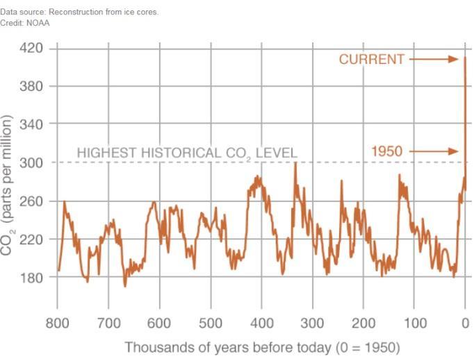


Figure1.2HistoricallevelsofCO24

Increased rate of wildfires, hurricanes, floods and unpredictable weather patterns have higher occurrence. Each year untypical weather causes destruction, large economic losses, losses of forests and fertile land. It is expected that the global GDP will decrease by 18% until 2050 if no mitigating actions are taken and temperatures continue to rise. The cities are getting hotter and more polluted. The “smog” has been present since the early industrial cities, and until this day this issue has continued to worsen and threaten the human health. 9 out of 10 people worldwide breathe polluted air causing allergic, pulmonary, cardiovascular and other health issues.

Figure1.3Environmentalchanges

Sustainable Building Design 17
4 climate.nasa.gov
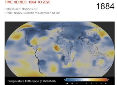
The temperature variations are not unknown in our planets history. Cycles of little ice ages have occurred within the period of 14th-19th century. In the period of 10000 b.c. - 1900 a.d., the temperatures have varied by 2 to 5°C. However, in the period of 1900-2020 they have increased by 2°C up to even 6°C, such as in the Siberia. The globalmean temperature in 2020 is 1.2 °C above the average temperature5 .
Most of the warming occurred in the past 40 years and the years 2016 and 2020 are tied for the warmest year on record at the time of this writing. Global surface temperature in the first two decades of the 21st century (2001-2020) was 0.99 [0.84- 1.10] °C higher than 1850-1900 (which is considered as pre-industrialcomparative period for globaltemperature targets[2]), Fig. 1.4 In 2020 the land average temperature has increased by 1.96 (± 0.04°C) while the ocean surface temperature, (not considering the sea ice regions), has increased 0.82 (± 0.06)°C6
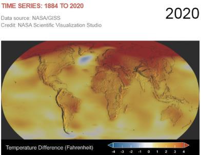
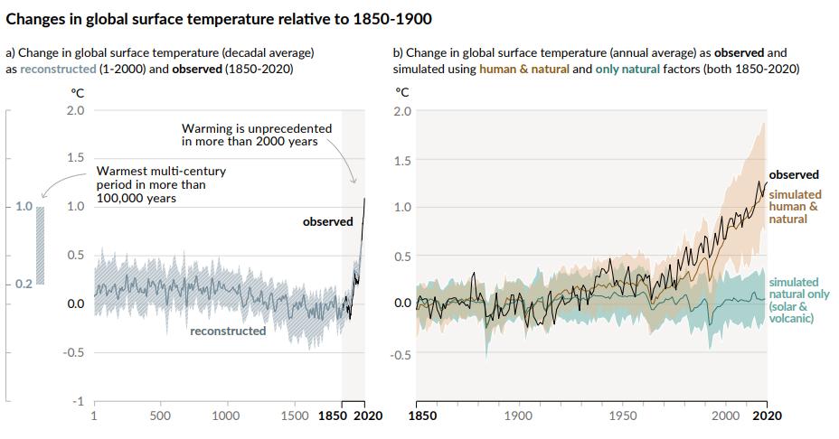
Figure1.4Globalsurfacetemperaturechanges[2]
Figure1.5Earths`temperaturecomparison
Due to the warming, all around the planet enormous glaciers and sea ice are rapidly disappearing in front of our eyes. The snows of Kilimanjaro have melted more than 80 5 {Citation} 6http://berkeleyearth.org/global-temperature-report-for-2020/
Sustainable Building Design 18
percent in the last 100 years. Glaciers in the Himalaya are melting so fast that scientists predict that they could disappear in only 15 years from now. Arctic sea ice has declined by about 10 percent in the past 30 years. Land areas generally warm up twice as much than the ocean7, but even at a slower pace the oceans` warming is a potential disaster for the ocean life.
It is estimated that one million species are at risk of extinction over the next decade[3].
The melting ice has caused raising average global sea level between 10 and 20 centimeters in the past hundred years and it's only the beginning. Large part of the humanity lives close to the coasts. More than a hundred million people worldwide live within a meter of mean sea level, while 40% of the world's population lives within 100kilometers. On the map we can see in the regions marked in red the coastal areas with more than 70 million inhabitants. The continuous rise of the sea levels will instigate chain reaction, causing migrations, economic loss, socialrestructuring, naturaldamage and many unforeseen events.
Greenhouse gas emissions
A small number of countries contribute the largest share of greenhouse gas emissions. The top 10 emitters account for more than 68% of annual global GHGs. Most of them are countries with large population and economies which together account for over 50% of the global population and almost 60% of the world’s GDP. China being the largest emitter has 26% share in the global greenhouse gas emissions, followed by the United States at 13%, the European Union at 7.8% and India at 6.7%. From the 1990 levels, the global annual greenhouse gas emissions have risen by 41% and counting
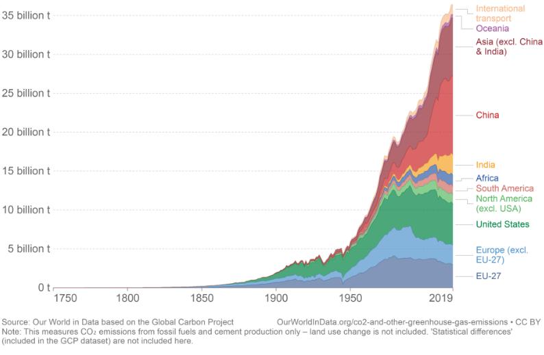
Figure1.6Emissionsbyworldregion8
The greenhouse gasses, consist of CO2, methane and other heat absorbing gases. Carbon dioxide (CO2) comprises 74% of greenhouse gas emissions and is produced by burning fossil fuel, transportation etc. Other GHGs, such as methane (CH4) and nitrous oxide (N2O) make
7 http://berkeleyearth.org/global-temperature-report-for-2020/ 8 https://ourworldindata.org
Sustainable Building Design 19
up 17% and 6.2% of total greenhouse gas emissions, respectively, mostly from agriculture, waste treatment and gas flaring, while the fluorinated gases (HFCs, PFCs etc.) from industrial processes contribute to 2% of global emissions. These gases are much more potent than CO2 in terms their global warming potential, and often provide overlooked opportunities for mitigation. As an example, nitrous oxide is 310 times more harmfulthan CO2.
Carbon dioxide (CO2) comprises 74% of greenhouse gas emissions.
Unsustainable urbanization
Urbanization based on unsustainable practices means increased resource consumption, larger pressure on the environment, on the fresh water demand, on the infrastructure etc., all having detrimentalconsequences to all living forms on our planet.
Cities account for about 70% of global carbon emissions and more than 60% of resource use.The rapid urbanization and population growth are outpacing the construction of adequate and affordable housing. On the other hand, cities are economic powerhouses creating up to 60% of the globalGDP growth.
The rapid urbanization and population growth are outpacing the construction of adequate and affordable housing
The rapid urbanization in the last decades has caused more than half of humanity to live in cities while it is forecast that approximately 70% of the world population will live in cities by 2050 , which is more than 6.5 billion people. Also, it is expected that 90-95% of the urban expansion in the next three decades will take place in the developing world. It is estimated that the buildings floor area worldwide will increase by 75% between 2020 and 2050, mostly in the developing economies. That means that globally, floor area equivalent to the surface of the city of Paris is added every week up to 2050 .
Conventional buildings
The total energy consumption has the largest share of the total greenhouse gas emissions with 30.4% Buildings contribute with 28% of the energy-related CO2 emissions and altogether with the construction industry (production of construction materials) comprise 38% of the total emissions[4] In the EU the buildings are held responsible for approximately 40% of the finalenergy consumption.
According to the Environmental Protection Agency (EPA), buildings in the United States account for:
36% totalenergy use
65% totalelectricity use
12% totalwater use
30% totalCO2 emissions
60% totalnon-industrial waste generated (from construction and demolition)
Sustainable Building Design 20
Among various building types, residentialbuildings are one of the largest contributors with up to 10.9% oftotalemissions, along with the road transport and industry, Fig 1.7, 1.8
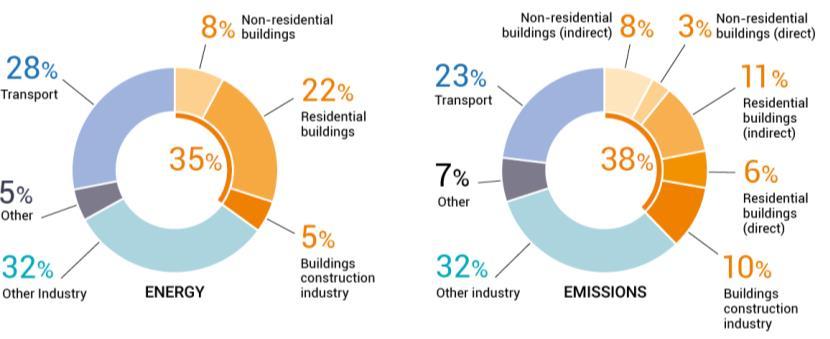
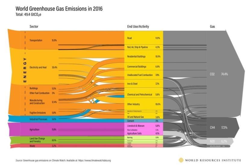
Figure1.7EnergyconsumptionandCO2 emissions
Figure1.8Globalshareofbuildingsandconstructionfinalenergyandemissions[4]
With the increase of the global population, estimated to reach 9.6 billion by 2050, the humanity would need the equivalent of almost three planets to provide the natural resources needed to sustain current lifestyles.
SustainableDevelopmentGoals
In order to address the global climate change issues, the concept of sustainability has been established. It is based on a holistic approach which unites the social, economic and environmental aspects, titled as the Triple Bottom Line [5], and aims to shape the interdependent future of nature and humanity. This approach demands fundamental change of values, practices and lifestyles. The present shortsighted view, in which people are concerned only with issues related to them and their closest environment within a short timeframe, mustbe substituted with a long-term vision for the future ofnature and humanity
"Sustainable development is development which meets the needs of the present without compromising the ability of future generations to meet their own needs." [6]
Sustainable Building Design 21
Therefore, the United Nations (UN), proposed a blueprint for peace and prosperity for people and the planet, now and into the future by establishing "The 2030 Agenda for Sustainable Development", adopted by allUnited Nations Member States in 2015.
In order to collectively and integrally address these issues as humanity the 2030 Agenda is comprised of 17 Sustainable Development Goals (SDG) (succeeding the Millennium Development Goals set in 2000), 169 targets with 232 indicators, designed to ensure the future prosperity and coexistence of the humanity and the nature.
9
Figure1.9SustainableDevelopmentGoals

The Goal 11 - Make cities and human settlements inclusive, safe, resilient and sustainable is addressing the topic of this writing. For this goal several targets are set to be achieved by 2030, among which are: to ensure access for all to adequate, safe and affordable housing and basic services and upgrade slums; to enhance inclusive and sustainable urbanization and capacity for participatory, integrated and sustainable human settlement planning and management in all countries; to reduce the adverse per capita environmental impact of cities, including by paying specialattention to air quality and municipaland other waste management etc.
TheParisAgreement
At the Conference of the Parties - COP 21 in Paris on 12 December 2015 the Paris Agreement was achieved which entered into force on 4 November 2016. It is a highly important legally binding international treaty on climate change, adopted by 196 countries.
Sustainable Building Design 22
9
https://www.un.org/sustainabledevelopment/
The 190 countries that have signed the Paris Agreement, are held responsible for the 93% of the emissions[7].
With the Paris Agreement, countries have agreed to limit warming well below 2°C with a target to 1.5°C. The ongoing manifestations of climate changes, such as melting ice caps, uncommon weather changes, often accompanied by violent storms or fires occur under the presentglobal temperature increase of1.2°C.
More than 130 countries had set targets or are in the process of setting targets for emissions reduction to net zero by 2050. More than 90 have submitted national action plan for emissions reduction, however their planned combined emissions reductions by 2030 are not enough to achieve the 1.5°C goal[8]. Therefore, sharp emissions cut is an imperative in the following 5 to 10 years in order to keep global warming below target temperature and protect the naturaland human environment.
Sharp emissions cut is an imperative in the following 5 to 10 years in order to keep global warming below 1.5°C.
To mitigate the climate impact, the GHG emissions need to be halfed by 2030 and the humanity needs to achieve net-zero emissions by 2050. The Intergovernmental Panel on Climate Change (IPCC) in the Special Report on Global Warming of 1.5˚C states that if the world reaches net-zero emissions by 2040, the chance of limiting warming to 1.5°C is considerably higher. The sooner the emissions are tackled, the more realistic is the achievement of net zero future. However, in 2019, the construction sector and buildings instead of improving, they had moved further away from the goals set with the Paris Agreement[4]
Therefore, in August 2021, the Intergovernmental Panel released a new report, alarming for a Code Red for the Humanity, urging that there is no time for delay and no room for excuses[9] As IPCC states, the global mean temperature in 2021 is 1.2 °C above the average temperature and the 1.5°C limit is likely to be hit sooner than expected.
TheEuropeanGreanDeal
In December 2019. the EU adopted the European Green Dealin which the Commission sets out
"a new growth strategy that aims to transform the EU into a fair and prosperous society, with a modern, resource-efficient and competitive economy where there are no net emissions of greenhouse gases in 2050 and where economic growth is decoupled from resource use. It also aims to protect, conserve and enhance the EU's natural capital, and protect the health and well-being of citizens from environment-related risks and impacts”. To reach these objectives, “energy efficiency must be prioritised”.
Sustainable Building Design 23
With the European Green Deal, all of the 27 EU Member States committed to making the EU the first climate neutral continent by 2050 To reach these objectives, “energy efficiency mustbe prioritized” in all sectors and industries.
EU sets out to be the first climate neutral continent by 2050 These ambitious targets are expected to create new opportunities for: innovation and investment and jobs, address energy poverty, reduce externalenergy dependency, improve the health and wellbeing,
Meeting these targets means that renewables should contribute to the energy supply of electricity with 40% by 2030 and 70-85% by 2050, promoting the uptake of renewables It is estimated that 35 million buildings could be renovated by 2030 while 160.000 additional green jobs could be created in the construction sector by 2030.
The Commission has therefore revised the Energy Efficiency Directive, together with other EU energy and climate rules, to ensure that the new 2030 target of reducing greenhouse gas emission by at least55% (compared to 1990) can be met.
The revised directive also requires EU countries to collectively ensure an additional reduction of energy consumption of 9% by 2030 compared to the 2020 reference scenario projections. This 9% additional effort corresponds to the 39% and 36% energy efficiency targets for primary and final energy consumption outlined in the Climate Target Plan, and is measured againstupdated baseline projections made in 2020.
The proposal nearly doubles the annual energy savings obliging EU countries to achieve new savings each year of 1.5% of final energy consumption (from previous 0.8%) from 2024 to 2030
The Commission proposes to restore Europe’s forests, soils and wetlands which will increase absorption ofCO2 and willmake our environment more resilient to climate change. The EU intends to share these proposals with its international partners at the UN’s COP26 Climate Change Conference in Glasgow in November 2021 and to stimulate joint global effort for achieving these highly urgent targets.
Net-ZeroEmissionsandtimeframe
Reaching net-zero emissions means that all human related GHG emissions will be as close to zero. The remaining GHGs should be balanced with carbon removal approaches, such as
Sustainable Building Design 24
forestation or direct air capture and storage technology10 . In the case of limiting warming to 1.5°C, the CO2 emissions needs to reach net-zero between 2044 and 2052, while total GHG emissions must reach net-zero between 2063 and 2068[10, p. 2]. Therefore, there is an urgent need to quadruple the solar and wind capacity by 2030 and triple renewable energy investments to maintain a net zero trajectory by mid-century.
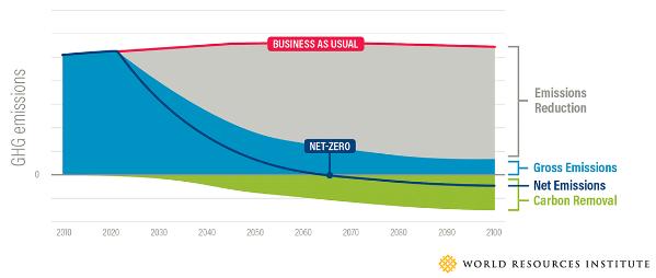
Figure1.10Reachingclimateneutrality[11]
The International Environmental Agency (IEA) estimates that 85% of the building stock needs to be net-zero compliant by 2050, meaning that all new buildings need to be net-zero by 2030 and the existing buildings to be net-zero retrofitted by 2050. In order to achieve the goals for net-zero carbon buildings by 2050, the IEA estimates that there is a need to decrease by 50% the direct building CO2 emissions and indirect building sector emissions decline through a reduction of 60% in power generation emissions by 2030. This means that in the period of2020-2030the yearly reduction ofbuilding related emissions should be 6%[4].
In July 2021, the European Commission submitted a proposal for a DIRECTIVE OF THE EUROPEAN PARLIAMENT AND OF THE COUNCIL on energy efficiency (recast)[12] stressing the importance of energy efficiency as a key area of action for achieving full decarbonisation of the Unions` economy.
Sustainable Building Design 25
10
https://www.wri.org/insights/net-zero-ghg-emissions-questions-answered
2SustainableBuildings
D-r Aleksandar Petrovski, Lepa P. Hristovska, Atanas Petrovski
In the previous chapter we have seen the detrimental consequences the buildings have onto the environment in terms of energy consumption and carbon emissions. In order to mitigate them, the concept of sustainability is being implemented in every human related domain and activity, even though not with the desirable pace. However, given the new agreements and guidelines established by the world governments and within the construction industry it is expected we will gain a faster transition towards sustainable buildings. In this chapter we will outline the sustainability in architect, go through common definitions and have an overview on sustainability assessment schemes. Afterward we will discuss buildings` carbon reduction possibilities and examine severalcase-studies of sustainable residentialbuildings.
2.1. Conventionalresidentialbuildings
Energy performance of residential buildings
Buildings, during their operation spend electricity to meet the human activities and needs for comfort, working, leisure etc. The electricity consumption in European dwellings is shown in Figure 2.1, according to its means for use, whether it is for heating, lighting, appliances, cooking etc.. In almost all EU countries the heating energy demand is being the dominant one. Regarding the energy sources, the natural gas accounted for 32% of the EU final energy consumption in households, electricity for 25%, renewables for 20% and petroleum products for 12%[13]
Figure2.1Energyconsumptionbyenduse perdwelling[13]
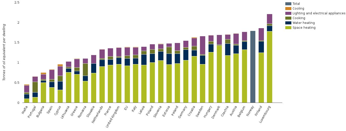
Sustainable Building Design 26
The dominant use of energy by households in the EU is for heating their home, Figure 2.1. However, such average energy consumption does not clearly depict the considerable differences depending on climate, the building type, the buildings` design, activity in the households in different countries and climatic regions, etc. While the share of space heating is above 80% in colder climates, in warmer climates it is lower, around 50% and less.
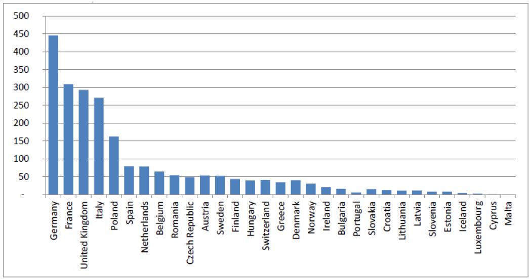
Figure2.2Spaceheatingofresidentialbuildings(TWh)
11
The average final energy consumption in the residential sector by use in the EU is shown in Figure 2.3. The share of energy for heating the homes is 63.6 % of final energy consumption in the residential sector, electricity used for lighting and most electrical appliances represents 14.1 % (this excludes the use of electricity for powering the main heating, cooling or cooking systems), while the proportion used for water heating is slightly higher, representing 14.8 %. Main cooking devices require 6.1 % of the energy used by households, while space cooling and other end-uses cover 0.4 % and 1.0 % respectively. Heating of space and water consequently represents 78.4 % of the finalenergy consumed by households[13]
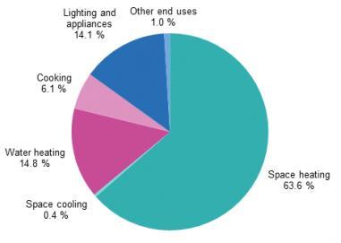
Also, due to the global warming and climate changes, the global cooling consumption of the residentialsector is expected to increase up to 34% in 2050and 61% in 2100 [14].
Figure2.3Finalenergyconsumptionintheresidentialsectorbyuse[13]
11
Sustainable Building Design 27
Communication from the Commission to the European Parliament, the Council, the European Economic and Social Committee and the Committee of the Regionson anEU Strategy for Heating and Cooling, 2016.
Buildings and human health
People, mostly spend their time indoors, up to 90% their time, in travel 5% and 5% outdoor [15] This stresses the importance of the quality of the buildings and the quality of indoor environment.
The intensive use of mechanical systems for conditioning the space and creating an “artificial” interior climate is a cause for a large number ofhealth issues and worsening health conditions among buildings occupants. The health related issues that arise due to unhealthy indoor environment are known as the Sick Building Syndrome (SBS)
Studies show that 23% of employees in office spaces show SBS, manifested in allergic reactions, respiratory difficulties and asthma[16]. The SBS is responsible for a large number of sick leaves among employees. It is having a significant impact on productivity, estimated to 2% in the US, resulting in 60billion losses annually.
On the other hand the sustainable buildings are proven to bring benefits to the mental and physical health of the inhabitants.It is confirmed that the users of sustainable buildings have larger productivity and less sick-leaves by 15%[17], [18] In educational buildings, the adequate daylight contributes to 20-26% higher results among students[19]. According to a study in schools it is proven that when the quality of air and lighting are improved, the students perform better by 15-23% [20]
Research on the impact of the esthetical values onto the life quality is confirmed that those cities and environments with “scenic”, i.e. high aesthetic qualities, positively impact the inhabitants health[21]
Economic aspects of buildings
According to the US Green Building Council [19], sustainable buildings, compared to the conventionally designed buildings have 2-7% larger upfront construction costs. Some articles state that sustainable buildings are more expensive by 17%, however, according to the World Business Council on Sustainable Development the difference in costs is only 5%. The cost for constructing a conventional and sustainable building can also vary depending on the climate conditions which are reflected in the buildings` design. Some buildings would require thicker insulation as in colder climates and compact form, while buildings in warm humid environment would have less compact shape with larger canopies etc
The costs of conventional buildings life-cycle are largest during the operational phase and are energy consumption related[22] The costs of a sustainable are larger upfront due to the investment in high performing building envelope and systems, while during the operation they are designed to be nearly zero, or even producing electricity. The larger upfront costs are considered to be the main obstacle for their broader acceptance[23].
Sustainable Building Design 28
Figure2.4Costsduringconventionalbuildinglife-cycle
However, analysis of sustainable buildings` long-term benefits shows a positive return on investment with a payback between 6-8 years due to the high energy efficient performance and energy savings. Also, they are having an increased market value by 4-7% compared to traditionalbuildings[24].
The demand for sustainable buildings is increasing and the number of buildings designed on sustainable principles is rises steadily worldwide across all continents. The global net zero energy buildings market share value in 2018 is estimated at $896.6. mil, while it is forecast in 2024 to reach $2.1 bil. Cost of office net zero buildings (2025) is 6.2% higher than standard. Looking out to new technologies and standards, by 2030 the cost of net zero buildings is estimated to be 8-17% than standard.
2.2. Sustainablebuildings
The concept of sustainability, based on the integration of the environmental, social and economicaspects is implemented in the construction industry
The EnvironmentalProtection Agency (EPA) defines Sustainable Construction as "the practice of creating structures and using processes that are environmentally responsible and resource-efficient throughout a building's life-cycle from siting to design, construction, operation, maintenance, renovation and deconstruction”.
Similarly, Sustainable Buildings can be defined as:
“buildings that have minimum adverse impact on the built and natural environment, in terms of the buildings themselves, their immediate surroundings and the broader regional and global setting”.
Therefore, the sustainable architecture is based on decreasing the resource consumption, improving the human wellbeing and health while taking into consideration the economic and social circumstances in which it occurs. The integration of all of the three aspects of sustainability in the buildings` design is of utmost importance. We cannot design a building which has good environmental performance and high energy performance, while it is poorly
Sustainable Building Design 29
Use 72% Construction 22% Maintenance 4% Transport 1% Recycling 1%
architecturally designed, unfunctional, uncomfortable and not economically feasible. Or, we cannot have a building which is economically justifiable, while it is not environmentally friendly. Therefore, the integration of the three main aspects of the sustainability in the buildings` design and their fulfilment to the best values possible, ensures a successful delivery of a sustainable building.
Regenerativedesign
In addition to the concept of sustainability, the regenerative concept has been promoted. We've seen that the sustainability is based on doing less harm to the environment and using less resources, while the regenerative concept is defined as enabling social and ecological systems to maintain a healthy state and to evolve [25]. The intent of the regenerative design is to deliver building that is adapted to and utilizing the potential of the natural and climatic context while creating synergistic relationship between the climate, ecosystems and human life[26].
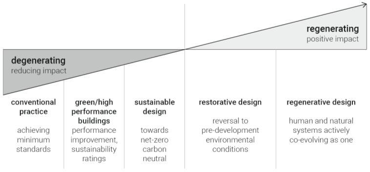
For comparison, we can notice the difference between the following concepts[25], such as: Sustainability is based on limiting the buildings` impact onto the environment and to reduce the negative implications ofthe resource consumption to acceptable levels. Restorative means that there is a positive impact onto the social and ecological systems and they are returned back to a healthy state.
Regenerative means enabling social and ecological systems to maintain a healthy state and to evolve.
Figure2.5Diagramofdesignconceptsimpact[25]
Circulareconomy
The circular economy is an economic model promoting a closed loop system of resource consumption aiming to minimize waste while promoting re-use, recycling and protection of resources. This concept can be applied in the construction industry on different scales, such as on a product level and the production of construction materials, as well as on a building-
Sustainable Building Design 30
scale level, taking into consideration the whole life-cycle of the buildings, until to their end of life stage.
A circular economy is a concept that is restorative or regenerative by intention and design. It replaces the linear economy and its ‘end of life’ concept with restoration, shifts towards the use of renewable energy, eliminates the use of toxic chemicals and aims for the elimination of waste through the design of materials, products, systems that can be repaired and reused[27].
Severalprinciples ofCircular Economy are defined, such as[28]:
1. Eliminate waste, pollution, negative social& environmentalimpact,
2. Keep products and materials in use as long as possible,
3. Regenerate naturalsystems.
More on circular economy is presented further in the latter chapters.
2.3. Energy-performancebuildingsdefinition
As the requirements for the energy-performance of buildings have changed and have been raised throughout the years, severalcategories ofbuildings can be met, such as:
Low-energy houses are buildings with annual heating thermal loads below 80 kWh/m2a
Three liter building has an annual heating energy consumption of 30 kWh/m2a (or 3 liters of light fuel oil/m2 per year), with an envelope airtightness of n50≤1h–1 (less than 50airchanges/hour).
Passivhauss are designed by utilizing the potential of passive solar heating and cooling techniques. Their annual energy consumption for heating is less than 15 kWh/m2a with a total consumption of primary energy is less than 120 kWh/m2a, the annual consumption of electricity is ≤18kWh/m2a, and the heat losses are ≤10W/m2 .
The airtightness less than 50 air changes/hour.
Nearly Zero-energy buildings (NZEB) are defined with the European Energy Performance of Buildings Directive EPBD as a building that has a very high energy performance.
Zero-energy buildings, like NZEBS, are heavily insulated with almost no thermal bridging. They are designed in such a manner that actively and passively exploit the solar energy, reducing the need for conventional heating systems. The need for heating and electrical energy is entirely produced through renewable sources and are not dependent upon the publicelectrical grid.
Plus-energy house is an energy self-sufficient building whose energy needs are entirely produced through renewable sources but also using technology for storing its produced excess energy.
Sustainable Building Design 31
All of these buildings are designed in such a way that they utilize sustainable and passive design principles according to the given climate conditions. The buildings envelope is designed as a very high-performance, meaning it has sufficient and above average level of thermal insulation and it is airtight. Attention is given to detailing in order to avoid or reduce the thermalbridges and thermally insulated windows are used.
0 10 20 30 40 50 60 70 80 90
low energy house three litre house passive house nearly zeroenergy house energy selfsufficient house
Figure2.6Energyefficientbuildings
plus-energy house
The passive buildings mostly rely on passive design principles, while the zero-energy, energy self-sufficient buildings and plus-energy building require additional active technologies which can be an economic drawback due to the larger upfront investment.
The ventilation of the buildings is natural and mechanical which in winter is controlled via efficient heat recovery systems. The heating is provided by efficient heating systems (heat pumps etc.) as an addition to the passive solar heating.
In this book we will focus on the architectural design features which can improve the buildings` sustainable and even regenerative performance. The mechanical and other active systems and equipment required for achieving full energy autonomy is out of the scope of this writing as they do not fall under the architectural design domain. Architects need to be familiarized with those technologies in order to successfully implement them in the buildings` design, stressing the need for a collaborative and integrative project team and management with all of the involved engineers and stakeholders.
2.4. Nearly-zero-energybuildings
The Energy Performance of Buildings Directive (EPBD) defines the nearly-zero energy buildings as: “a building that has a very high energy performance”, while there are no defined metrics and levels for classifying a building as a nearly-zero energy one. Its energy needs should be covered to a very significant extent by energy from renewable sources.
As concrete numeric thresholds or ranges are not defined in the EPBD, these requirements leave room for interpretation and thus allow EU countries to define their nearly zero-energy buildings (NZEB) in a flexible way, taking into account their country-specific conditions.
Sustainable Building Design 32
Therefore, nearly zero-energy buildings (NZEB) definitions differ significantly from country to country.
The nearly zero-energy buildings (NZEB) radar clusters energy efficiency qualities in 4 different categories that have been defined at national levels:
1. Net zero energy buildings / Plus energy buildings
2. Nearly zero-energy buildings (NZEB) according to nationaldefinitions
3. Buildings with an energy performance better than the nationalrequirements in 2012
4. Buildings constructed/renovated according to national minimum requirements in 2012
With the Energy Performance of Buildings Directive (EPBD) it is defined that all new buildings must be nearly zero-energy buildings (NZEB) from 2021. Additionally, since 31 December 2018, allnew publicbuildings need to be NZEB.
The mechanism of EPBD demands that when a building is sold or rented energy performance certificates must be issued accompanied with inspection of heating and air conditioning systems established at a national level. There is a great potential for energy savings in the building sector, since 75% ofthe EU building stock has poor energy performance.
There is a great potential for energy savings in the building sector, since 75% of the EU building stock has a poor energy performance.
The EU countries must:
• provide nationalfinancialmeasures to improve the energy efficiency ofbuildings,
• establish strong long-term renovation strategies, aiming at decarbonizing the nationalbuilding stocks by 2050, with indicative milestones for 2030, 2040and 2050;
• set cost-optimal minimum energy performance requirements for new buildings, for existing buildings undergoing major renovation, and for the replacement or retrofit of building elements like heating and cooling systems, roofs and walls
The 2020 energy efficiency target might not have been achieved, among causes such as Covid-19 pandemic, however, the sum of national contributions communicated by Member States of the EU in the National Energy Climate Plans (NECP) falls short of the Union’s level of ambition of32,5% in 2030.
Another issue is that the Energy Efficiency Directive just sets the overall energy efficiency objectives and delegates the dynamics of carrying out the actions to the Member States upon their decision.
Further, the European Commission (EC) has ambitious targets for renovating buildings and proposes to the:
Member States to renovate at least 3% of the total floor area of all public buildings annually
Sustainable Building Design 33
seta benchmark of49% of renewables in buildings and
require increase ofuse ofrenewable energy in heating and cooling by +1.1%
However, the economic investments are not sufficient to support these goals. Even though there is a slight increase in sustainable and energy-efficient measures, amounting to $152 billion in 2019, they are a small portion of the $5.8 trillion spent in the construction sector. It is estimated that for every $1 spent on energy efficiency measures, $37 are spent on conventional construction technologies and materials[4]. Therefore, strategies and incentives to make buildings net-zero energy and zero-carbon are a key part of the global decarbonisation strategy and must become the primary form of building construction across alleconomies to achieve net zero emissions by 2050[4]
Strategies to make buildings net-zero energy and zero-carbon are a key part of the global decarbonisation strategy and must become the primary form of building construction across all economies to achieve net zero emissions by 2050[4].
Nevertheless, constructing net-zero buildings can be achieved by available technologies and design approaches, to name a few, such as: sustainable and bioclimatic building design, conventional and advanced high-performance facade systems, sustainable materials and material-efficient building design etc. Also, digitalization and smart technologies can substantially contribute, such as building management systems, smart materials, smart technologies etc. In order to achieve net-zero carbon building sector by 2050, all stakeholders involved in the construction industry need to contribute to the effort to reverse this trend and there must be an increase in decarbonization actions and their impact by a factor of 5[4]
In order to achieve net-zero carbon building sector by 2050, all stakeholdes involved in the construction industry need to contribute to the effort to reverse this trend and there must be an increase in decarbonization actions and their impact by a factor of 5[4]
2.5. Net-ZeroCarbonBuilding
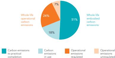
As we have seen previously, buildings are held responsible for carbon emissions during their operational phase, by using non-renewable energy which are referred to as operational carbonemissions
Also buildings are responsible for the carbon emissions which are emitted during the lifecycle ofthe construction materials which are referred to as embodiedcarbonemissions. In this regard, the net-zero carbon buildings can be defined according to two aspects, such as[29]:
Net zero operational carbon emissions and Net zero embodied carbon emissions.
Sustainable Building Design 34
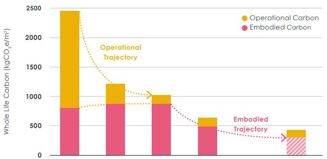
The decrease of the operational carbon emissions and embodied carbon emissions leads to a net-zero whole life- carbon building The energy consumption and related carbon emissions are decreasing with energy efficient policies and sustainable design. Therefore, the embodied carbon emissions from the construction materials is becoming more significant, as it is willhave a larger share in the totalcarbon emissions ofthe building.
Figure2.7 Reductionofcarbonemissions[30]
Figure2.8CarbonemissionsintypicalresidentialbuildinginUK[29]
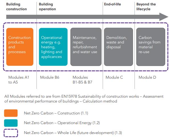
However, net zero whole life carbon is not yet proposed due to limitations regarding reporting of carbon during the maintenance, repair, refurbishment and end-of-life phase ofa building’s lifecycle[29].
Instead, buildings are encouraged to aim for net zero carbon in construction (new buildings and major refurbishments) and for net zero carbon operational energy (existing buildings), until greater familiarity with whole life carbon impacts has been achieved. In terms of lifecycle ofbuildings the net zero carbon scopes are presented in figure below.
Sustainable Building Design 35
Figure2.9Threenetzerocarbonscopes[29]
a) carbon emissions from conventional building b) reduced of carbon emissions in ultra-low energy building
Figure2.10Reductionofcarbonemissiontargets[30]
Net zero embodied carbon
The net zero embodied carbon, considers emissions emitted during the building’s materials production phase, their transport and installation on site as well as their disposal at end of life such as, disassembly, demolition, recycling or up cycling. Net zero carbon construction can be made from recycled, re-used or natural materials and it is encouraged to be designed for disassembly at the end ofbuildings life cycle, in line with principles ofthe circular economy. A building is net-zero embodied carbonwhen:
“the amount of carbon emissions associated with a building’s product and construction stages up to practical completion is zero or negative, through the use of offsets or the net export of on-site renewable energy.”
Net zero carbon operational energy
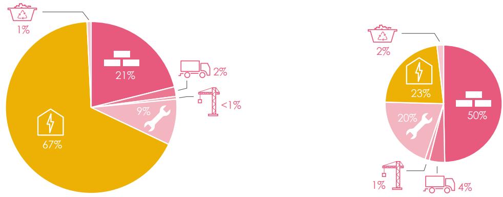
Operational energy is the energy consumed in the building for providing heating, hot water, cooling, ventilation, and lighting systems, as well as equipment such as fridges, washing
Sustainable Building Design 36
machines, TVs, computers, lifts, and cooking. Building that is net zero operational carbon means that it does not burn fossil fuels and is 100% powered by renewable energy. Net zero carbon operational energy is achieved when a building’s total annual net CO2e emissions equalzero, or allcarbon impacts are balanced by carbon credits.
Therefore, net zero carbon operationalenergy is when:
“the amount of carbon emissions associated with the building’s operational energy on an annual basis is zero or negative. A net zero carbon building is highly energy efficient and powered from on-site and/or off-site renewable energy sources, with any remaining carbon balance offset.”
Whole life net zero carbon building is defined:
“When the amount of carbon emissions associated with a building’s embodied and operational impacts over the life of the building, including its disposal, are zero or negative.”
Whole life carbon encompasses all carbon emissions that arise as a result of the energy used in the construction, operation, maintenance and demolition phases ofa building.
Carbon offsetting can be used to achieve net zero embodied carbon, however it is often related to transparency and effectiveness.
A building that is whole life net zero carbon meets the operationalzero carbon balance and is 100% circular, this means that 100% of its materials and products are made up of re-used materials and the building is designed for disassembly such that 100% of its materials and products can be re-used in future buildings. When construction, transport and disassembly is carried out with renewable energy there will be zero carbon emissions associated with the embodied carbon.
Net zero energy and zero energy
Also, we can define the following terms, “netzeroenergy” and “zeroenergy” .
The net zero definition almost always addresses only the site energy usage. The annual of energy consumption must be less than or equal to the amount of renewable energy created onsite.
The zero energy focuses on balancing onsite production with source energy usage, which accounts for the amount of energy it takes to provide the site with the needed energy, accounting for transmission losses and energy generation efficiency. This definition is fueldependent, meaning the offset calculation must account for the differences in source energy needs for different fuelsources.
Sustainable Building Design 37
2.6. Sustainabilityassessmentandtargets
In order to measure the sustainability of a building, its performance and fulfillment of the various demanding criteria, several sustainability assessment methodologies and schemes are developed, such as: LEED (USA), BREEAM (UK), DGNB (Germany), Open House (EU) etc. They based on measurable indicators organized in categories. The sustainability assessment take into consideration the local specific conditions, climate, transport, energy source etc., and several of the sustainability assessment schemes provide adjustment of their measurement systems and indicators to the countries specifics Within the EU, the most common ones are BREAM, followed by LEED, DGNB etc., and we will shortly outline some of them.
BREEAM
BREEAM is launched in 1990 in the UK by The Building Research Establishment (BRE). The assessment system is based on a bottom–up methodology. The key criteria and features of BREEAM are structured hierarchically into Issues, Categories, and Criteria levels. At the top level, there are ten distinct issues (the maximum number of obtainable credits is shown in parentheses): Management (22), Health & Well-being (14), Energy (30), Transport (9), Water (9), Materials (12), Waste (7), Land Use & Ecology (12), Pollution (13), and Innovation (10).
The fore mentioned issues consistof totalof 69 categories, which are comprised of 114 criteria which need to be evaluated The criteria are assigned a certain number of points which are aggregated per category. The points are weighted with predetermined factors in order to sum the final score. The maximum score in the BREEAM assessment is 100 points, with an additional 10points for an extra category, which includes innovation criteria.
Sustainable Building Design 38
According to the number of points achieved from the assessment, the buildings can be rated as: unclassified (<30points), pass (≥30points), good (≥45points), very good (≥55points), excellent (≥70 points), and outstanding (≥85points).
BREEAM provides possibilities to adapt the assessment to the specifics of different countries. It involves a local assessor, knowledgeable on the local specifics, who has a role as a consultant and an on-site auditor.
In the BREEAM for new-build domestic (international only) and non-domestic buildings environmentalsections and assessment issues are:
Sustainable Building Design 39
Table2.1BREEAMcriteria
Management
Project brief and design
Life cycle cost and service life planning
Responsible construction practices
Commissioning and handover
Health and wellbeing
Visual comfort
Indoor air quality
Safe containment in laboratories
Thermal comfort
Acoustic performance
Accessibility
Hazards
Private space
Water quality
Energy
Materials
Reduction of energy use and carbon
Energy monitoring
External lighting
Low carbon design
Energy efficient cold storage
Energy efficient transport systems
Energy efficient laboratory systems
Energy efficient equipment
Drying space
Water
Water consumption
Water monitoring
Water leak detection
Water efficient equipment
Waste
Construction waste management
Recycled aggregates
Operational waste
Speculative floor and ceiling finishes
Adaptation to climate change
Functional adaptability
Pollution
Impact of refrigerants
NOx emissions
Surface water run-off
Reduction of night time light pollution
Reduction of noise pollution
Life cycle impacts
Hard landscaping and boundary protection
Responsible sourcing of materials
Designing for durability and resilience
Material efficiency
Transport
Public transport accessibility
Proximity to amenities
Alternative modes of transport
Maximum car parking capacity
Travel plan
Land use and ecology
Site selection
Ecological value of site and protection of ecological features
Minimizing impact on existing site ecology
Enhancing site ecology
Long term impact on biodiversity
Innovation
Innovation
Sustainable Building Design 40
Aftercare
Insulation
DGNB
DGNB was launched in 2009 by the Deutsche Gesellschaft für Nachhaltiges Bauen (DGNB), with a release of an international version in 2014. The DGNB system includes three equally weighted categories such as: environmental, economic, sociocultural, and the functional quality. It also includes three more categories which have lower weight in the assessment, but important nevertheless: technical, process and site quality The weighting of the criteria is dependent on the building typology.
The maximum score is 100%, and certification can be rated as: DGNB Bronze (≥35 points), DGNB Silver (≥50 points), DGNB Gold (≥65points), and DGNB Platinum (≥80 points).
LEED
LEED is established in 1998 in the USA by the US Green Building Council (USGBC). The scoring system is based on a bottom–up methodology, where the indicators are assessed and their points are aggregated within a category. However, the points between categories are not weighted and the final score is a sum of the criteria. LEED for New Construction 2009 is structured into two levels, Categories and Points, which are similar to Issues and Categories in other schemes. The points scoring system is used. There are seven categories that cover (maximum number of points for each category in parentheses): Sustainable Sites (26), Water Efficiency (10), Energy and Atmosphere (35), Materials and Resources (14), Indoor Environmental Quality (15), Innovation in Design (6), and Regional Priority (4); the maximum possible totalscore is 110points.
In regard to the to the number of points awarded from the assessment, the buildings can be rated as: Unclassified (<40 points), Certified (≥40points), Silver (≥50 points), Gold (≥60points), and Platinum (≥80points).
Sustainable Building Design 41
Comparison of assessment points
The comparison ofBREAM, LEEDand DGNB categories, their similarities and differences, as well as points awarded are presented in Table 2.2.
Table2.2Comparisonofassessmentpoints
BREEAM points LEED points DGNB points Management 12 Sustainable site 26 Environmentalquality 22.5 Health and Wellbeing 15 Efficient water use 14 Economicquality 22.5 Energy 19 Energy and atmosphere 35 Socio-cultural and functional quality 22.5
Transport 8 Materials and resources 14 Technicalquality 22.5 Water 6 Indoor air quality 15 Process quality 10 Materials 12.5 Innovation and design process 6 Location quality 12 Land use and ecology 7.5 Regionalpriority 4 Waste 10 Pollution 10 Innovation 10 Sum 110 Sum 114 Sum 100
WELL Building Standard
WELL Building Standard is developed with a focus on the health outcomes of design, policy, and operational decisions in buildings, evaluating both the environmental performance and the human experience
There are ten categories (concepts) in the WELL v2 assessment, such as: air, water, nourishment, light, movement, thermal comfort, sound, materials, mind and community It is comprised of 108 features (indicators) with distinct health intents. The features are either preconditions or optimizations.Also, WELL is designed to work with the BREEAM and LEEDrating systems.
12 The locationquality isa cateogory whichisasessed by the local authorities.
Sustainable Building Design 42
The WELL certification has 4 levels according to the number of points awarded, such as: WELL Bronze (40 points), WELL Silver (50 points), WELL Gold (0 points) and WELL Platinum (80 points).
Living Building
The Living Building Challenge standard (LBC) is established by the International Living Future Institute and is a certifying scheme made of 20 imperatives, organized in seven categories, or petals, such as: Place, Water, Energy,Health+Happiness,Materials, Equity, andBeauty
The LBC intends to transform the conventional construction paradigm and approach to designing and constructing buildings which will have a positive and regenerative impact on "the greater community oflife and the culturalfabricofour human communities". The categories (petals) are consisted of imperatives (indicators), whereas: Place consists of four imperatives: Limits to growth, Urban Agriculture, Habitat Exchange, and Car-Free Living; Water has one imperative - Net Positive Water; Energy consists ofone imperative - Net Positive Energy; Health+Happiness consists of: Civilized Environment, Healthy Interior Environment, and BiophilicEnvironment; Materials has five imperatives: Red List, Embodied Carbon Footprint, Responsible Industry, Living Economy Sourcing, and Net Positive Waste; Equity has four imperatives: Human Scale+Humane Places, Universal Access to Nature and Place, Equitable Investment and JUST Organizations; Beauty has two imperatives: Beauty+Spirit and Inspiration+Education.
Professionals from the construction industry state that the Materials Petal has become the most challenging one, with the imperative Red List being a particularly difficult one to fulfill. The Red List is comprised of 22 of the worst-in-class materials and chemicals that are ubiquitous in the built environment. These are carcinogens, persistent organic pollutants, and reproductive toxicants, many of which are bio-accumulative, meaning that they build up in organisms and the broader environment, often reaching alarmingly high and dangerous concentrations as they travel up the food chain. The purpose of the Red List is to identify the compounds in the construction materials used and building products and to stimulate manufacturers to avoid the use of these toxic chemicals entirely from the whole life cycle of a product
However, the practice has shown that it is very difficult to obtain the list of all the compounds in the construction material/products from the manufacturer, due to different issues, such as patents, non-transparency etc. In order to overcome this difficulty the International Living Future proposed the Declare program which requires manufacturers to be transparent about their ingredients.
Sustainable Building Design 43
Declare
The Declare program, enables manufacturers to disclose the ingredients within their products. Through the Declare database, product ingredients are screened and vetted against the LBC Red List as it supports the design teams in their search for non-toxic, transparently disclosed materials
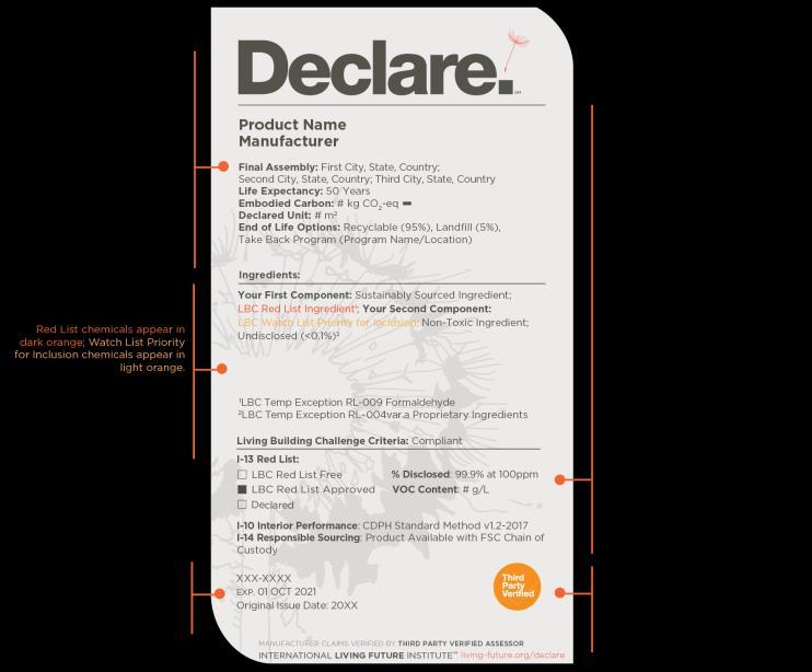
RIBA
Figure2.11ExampleoftheDeclarelabel[31]
The Royal Institute of British Architects (RIBA) has developed voluntary performance targets for operational energy use, water use and embodied carbon. The targets for residential buildings set for 2030 are as follows[32]:
Operational Energy <35kWh/m2 /y;
Embodied Carbon <625kgCO2e/m2 ;
Potable Water Use <75l/person/day;
daylighting >2% avg. daylight factor, 0.4 uniformity
TotalVOCs <0.3mg.m3
Formaldehyde <0.1 mg/m3
However, it the largest architectural companies in the UK develop their own measurement systems and there is a lack ofacceptance of the RIBA targets.
Sustainable Building Design 44
2.7. Carbonreductioninresidentialbuildings
The LETI guide focuses on four building archetypes that make up the majority of new buildings in the UK. They represent 75% of the new buildings likely to be built between now and 2050. LETI propose energy and carbon saving measures for small, residential building typologies as well as medium and large building with more than four floors. The measures are presented below.
ReducingOperationalEnergy
The recommendations are aligned with the Passivhaus standards, meaning that the total operational energy should be lowered to 35 kWh/m2.a, and the energy required for heating the building should be lowered to 15kWh/m2.a.
The building should have a compact form in order to reduce the operational energy consumption. Therefore, for smallscale buildings it is recommended to have a form factor of 1.7-25, while for medium to large scale buildings it is recommended to have a form factor of 0.81.5.
The buildings` envelope has to be well insulated, with low thermal transmittance, Table 2.1. Attention should be given to detailing and lowering the thermal bridging to 0.04 (y-value). The envelope should be airtight allowing maximum of 0.5ach at 50Pa.
Table2.3Thermaltransmittanceofbuildings`envelopecomponents
Construction element U values (W/m2K)
Walls 0.13-0.15 Floor 0.08-010 Roof 0.1-0.12 Exposed ceilings/floors 0.13-0.18 Windows 0.8-1 (triple glazing) Doors 1
Considering that the buildings energy losses are significant through the glazing it is recommended to have a triple glazing with U value under 1 W/m2K. Also, glazing area should be optimized relative to its orientation. The glazing should have g-value of 0.6-0.5. Additionally, the shading should be provided, designed to protect the building from the summer heat. The windows, or part of them, should be operable and enable natural ventilation and cross ventilation through the building. The area of the glazing should be carefully calculated according to the orientation of the façade, Table 2.2.The south façade should have the largest glazed areas with 20-25% of the

Sustainable Building Design 45
total area of the south facing wall, while for the remaining it is advisable to have an area maximum up to 10-15%.
Measures are proposed for lowering the energy demand for heating and hot water, such as: Ensure heating and hot water generation is fossil fuel free
Reduce heating and hot water peak energy demand
Installheating setpoint controland thermalstorage
The average content of heat supplied (gCO2/kWh.a) should be reported in-use
Maximum 10W/m2 peak heat loss (including ventilation)
Maximum dead leg of 1 liter for hot water pipework. "Green" Euro Water Label should be used for hot water outlets (e.g. certified 6 L/min shower head - not using flow restrictions).
ReducingEmbodiedCarbon
Choosing sustainable materials is crucial for achieving net-zero embodied carbon building. As we have seen previously, the embodied carbon can be classified according to the buildings` life-cycle.
In small residential buildings, the largest emissions are in the production (A1-A3) phase, with up to 80% contribution in the total embodied carbon emissions. The maintenance and replacement phase (B1-B5) has a significant 14% share, requiring design for durability in order to reduce these embodied emissions.
Figure2.12Embodiedcarbonemissionsinsmallresidentialbuildings
In a small residential conventional building, the average contribution to the total embodied carbon in a building is:
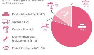
Superstructure - 30% ,
Substructure - 27%,

Internalfinishes - 20%,
Facade - 17%,
MEP - 5%.
It is required to reduce the embodied carbon by 40% or less than 500kgCO2/m2
Sustainable Building Design 46
In medium and large residential buildings the embodied carbon from the buildings` superstructure has a larger percentage share due to the larger number of floors. The share ofthe components are as follows:
Superstructure - 46% ,
Substructure - 21%,
Internalfinishes - 16%,
Facade - 13%,
MEP - 4%.
Also, the share of the maintenance and repair phase (B1-B5) is larger, compared to small buildings, contributing with 25%, while the product phase (A1-A3) participates with 64%.
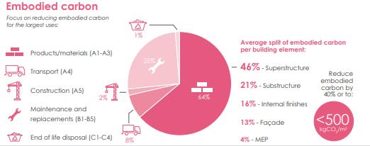
Figure2.13Embodiedcarbonemissionsperstructurecomponent
In order to reduce the embodied carbon emissions, the following recommendations are given.
Build Less
Use ofrecycled/reusable materials or localmaterials.
Recheck/rethink/revise the clients` brief and look for sustainable solutions
Seek for possibility ofdesign of multi-functional spaces
Materialefficient design, using standard component sizes or modular design.
Simplification ofthe design and construction means less embodied carbon
Build light
Optimize buildings` load bearing structure: spans, system and loads.
Build
wise
Ensure longevity of materialand systems specifications.
Structuralmembers should be designed for high utilization rate where possible.
Analyzing a site is an important activity at the start of a project and this can be extended to the identification ofways of reducing embodied carbon.
Possible opportunities include: Existing structures or buildings that can be reused or become a source ofrecycled materials should be considered. There may be locally sourced material options, reducing transport to site while allowing architecturalexpression of the context.
Sustainable Building Design 47
Designing a project around a site topography, reusing excavated soil and reducing the amount removed from site.
Build low carbon
Reduce the use of high embodied carbon materials. Identify the largest carbon contributors in the building especially in the early design phase and finding solutions. Take in consideration and apply when suitable naturaland renewable materials. Use prefabrication and Design for Manufacture and Assembly (DfMA) solutions for reduction of the embodied carbon.
Build for the future
Future uses and adaptability are considered Mechanically fix systems rather than adhesive fix so they can be demounted and reused or recycled, supporting a circular economy. Explore methods of creating longevity for materials without additional coatings, as they can reduce the recyclability of the material. The LETIembodied carbon targets for residentialbuildings are shown in Table below.
Table2.4Embodiedcarbontargets[30]
Residential building type Conventional building 2020 target 2030 target Whole life net zero target
Small scale residential 800 kgCO2e/m2 500 kgCO2e/m2 400 kgCO2e/m2
Medium scale residential 1000 kgCO2e/m2 600 kgCO2e/m2 500 kgCO2e/m2 350 kgCO2e/m2 250 kgCO2e/m2
Small scale and medium material use
0-10% are reused materials 0-10% are reusable material at the end of the buildings` life-cycle
30% of the material in the building is reused 50% of the material to be reusable at the end of the buildings` life-cycle
300 kgCO2e/m2 200kgCO2e/m2 0 kgCO2e/m2 -100 kgCO2e/m2
50% of the material in the building is reused 80% of the material to be reusable at the end of the buildings` life-cycle
100% of the material in the building is reused 100% of the material to be reusable at the end of the buildings` lifecycle
Embodied carbon target (building life cycle stages A1-A5). It includes Substructure, Superstructure, MEP, facade and internal finishes. Embodied carbon target (as previously) while including sequestration.
Sustainable Building Design 48
Carbonreductionguidelinesbycomponents

Recommendations are given for the following building components: substructure, superstructure, structure, envelope, finishes and furniture, site, design for manufacturing and assembly.
Substructure
Use fewer materials - Material efficient design should be applied and reduce the amount of materials used and the overall building weight. An optimization of the buildings layout can be performed. Reuse of existing substructures is stimulated, when possible. The whole life carbon impacts ofany thermalmass benefits should be taken into account
Use low carbon materials - Using recycled reinforcing steel. Opt for reusable formwork to reduce waste. For retaining walls pre-cast units can be considered, which may allow higher cement replacement, or using geotextile reinforced earth walls.
Use concrete alternatives such as Limecrete or Hempcrete where performance requirements allow, such as in ground floor slabs. Investigate low-carbon options such as timber piles (used in maritime applications), rubble trenches or dry-stack masonry. Use low-carbon below-ground insulation such as foamed glass.
Reduce waste - Use recycled aggregate where possible for ground work. On site waste can be effectively reduced by applying material efficient design, prefabrication and modular construction
Adaptability – It is advisable to design the building for future adaptation and changes in use. Also, the building should be designed for climate resiliency, as in the future there may be larger swings between wet and dry, or hot and cold weather.
Structure
Use fewer materials - Preserve and re-use existing structures wherever possible. Review and reduce loading requirements Reduce spans taking into account the impact on long-term flexibility. Design lighter facades that allow larger deflections at slab edges. Post-tensioning can be used in order to reduce the concrete volumes Forms that minimize material use, can be applied, especially in larger spans, such as coffered slabs. Using re-usable formwork to reduce the amount of waste. Using concrete as a surface finish to minimize use of other internalfinishes.
The buildings` structural elements can have a dual purpose, that is, they can serve as a shading device instead of constructing additionalshading elements to controlsolar gain.
Use low carbon materials - Consider the carbon impact of the cladding elements. Sustainably sourced cross laminated timber (CLT) usually has lower embodied carbon than steel or concrete. Consider low embodied carbon materials such as timber, rammed earth, straw bale panels etc. when possible.
Sustainable Building Design 49
When using steel, priorities high recycled content and shorter transport distances to site. Priorities highest possible cement substitution with industrial by-products and use recycled aggregates if they are available, such as : Pulverized Fuel Ash (PFA), aka ‘Fly ash’ and Ground Granulated Blast-furnace Slag (GGBS)
Reduce waste - Use prefabrication, modular design and Design for Manufacture and Assembly (DfMA)
Adaptability - Modular design – consider separating structural elements from functions that could be changed or moved as part of future adaptation. Consider spans, loads and structural grids that allow for changes and alternative uses, particularly if designing for typologies that may become obsolete in the near future (example: car parking)
Disassembly - Avoid composite materials (e.g. concrete on metal deck), which may be hard to deconstruct in future. DfMA strategies are most likely to allow for deconstruction and reuse. The connections between the structural components should mechanical instead of chemical in order to be easily disassembled, need to be visible and reversible
Buildings` envelope (facade and roof)
Buildings` facade can be carbon intensive depending on the materials used, supporting systems, fixings etc. In facades where steel or aluminum substructure is used it can significantly increase the embodied carbon (recycled steel is recommended). Also, the life expectancy of the facade system should be considered alongside the embodied carbon value.
Use fewer materials – Apply material efficient design, prefabricated and modular design in order to reduce total material use and weight. Using BIM platforms in the buildings 'design can facilitate this process.
Use low carbon materials - Perform detailed analysis of the materials applied in the buildings envelope and look for low-carbon materials as substitution.
All parts of the building component should be considered, such as for example the metal secondary framing in structural façade which often contains the most embodied carbon. Overallthe use of metal components should be reduced, or recycled components to be used. Some recommendations are:
Lime render or mineral wool can have a big impact in achieving lower embodied carbon.
Traditionalbrick build-up can be a low carbon solution and further enhanced by using recycled bricks and lime mortar. Use of lime mortar enables bricks to be reused at the end-of-life.
Timber framing can often be used instead ofmetal framing (fire regulations should be considered)
Alltimber should be from regulated and responsible sources.
Sustainable Building Design 50
Specify aluminum from a source that uses less carbon-intensive production methods – Polyester Powder Coating (PPC) aluminum is easier to recycle at the end-of-life than anodized aluminum, but needs more maintenance.
Reuse when possible materials, building elements and/or whole buildings previously utilized that are repurposed to construct a new or retrofitted building, in place of using virgin materials/new building elements.
Reduce waste - Where appropriate, design for repetition and off-site manufacture. Use standard sized components and materials
Adaptability – Façade design using Passive and Active design technologies. Façade that can adapt and regulate the heat transfer through it, thus contributing to lower energy consumption for heating, cooling and lighting. Use of shading devices, operable windows etc. Use ofadaptive facades, kineticfacades, smart materials and other technologies.
Disassembly - Consider prefabricated components with mechanical joints for easier disassembly.
Finishes, Furniture Fixtures and equipment (FF&E)
How to use fewer materials Utilize self-finishing internal surfaces like cement, concrete, timber etc. Use materials with recycled content Avoid harmfulchemicals like formaldehydes and VOCs. Take into consideration the need for maintenance, repair and replacement. Choose products that do not rely on adhesives so fabrics or finishes can be replaced.
Use low carbon materials Use materials with a high percentage of recycled content, (e.g. carpets). Compare materials EPDand apply materials with lower environmentalemissions
Reduce waste Durable materials will last longer, and require fewer replacement cycles over a building’s lifespan. Sometimes this enduring quality may come at a higher upfront embodied carbon cost but this may be a price worth paying to avoid later replacements. Take into consideration the expected lifespan of the building and likelihood for changes to interior finishes when specifying materials that are long-lasting and high embodied carbon.
Disassembly Internalfinishes are often in their nature difficult to disassemble for
Sustainable Building Design 51
Wet trades are particularly problematic, as products that are otherwise ‘good’ in terms of embodied carbon or recyclability may be rendered impossible to reuse/recycle by the nature of their fixing detail.
Composite materials in generalare less likely to be reused and recycled Avoid the use of glues and adhesives when possible, and choose fixings that will not affect the integrity ofthe material in the future, for example screws rather than nails. Where adhesives are required, opt for non-toxic and solvent free products. There are natural adhesives available that can make reuse more straightforward. There are issues with toxicity of glues with regards to disposal/reuse/recycling that will impact WLC.
Pitfalls
Cleaning requirements for different systems can increase their lifetime embodied carbon, as well as contributing chemicals to water systems, which then need to be eliminated through energy (and thus carbon) intensive processes.
Design for Manufacture and Assembly (DfMA)
Compare embodied carbon ofDfMA solutions with standard solutions. If DfMA is to be used, identify the elements by the end of RIBA Stage 2. Examples include, bathroom or WC pods, plant modules, facade elements, repeatable rooms, pre-fabricated structuralelements including twin wall, columns and planks. Engage the supply chain early. Lightweight materials are preferable for transportation purpose. Ensure the repeatable systems are designed for deconstruction.
Casestudyforachievingnet-zerocarbon
In a case study building improvements were made in order to achieve net-zero carbon in construction and operation. The characteristics ofthe models are shown in Table below.

Sustainable Building Design 52
Table2.5Modelsforloweringcarbonemissions[30]
Baseline Medium improvement High improvement Façade U = 0.22 kWh/m2.a U = 0.15 kWh/m2.a U = 0.13 kWh/m2.a Air Infiltration (at 50 Pa) 5 m3/hm2 m3/hm2 1 m3/hm2
Insulation
None Roof - 15 cm Wall - 5 cm Ground - 2.5 cm
Roof - 15 cm Wall - 5 cm Ground - 2.5 cm
Glazed area 51% 51% 29%
Glazing performance Double glazed U = 1.6 kWh/m2.a g value = 0.4
Triple glazing U = 1.1 kWh/m2.a g value = 0.5
Triple glazing U = 0.8 kWh/m2.a g value = 0.6
Case studies on mid-rise residential buildings show that by reducing the structural loads and use of low carbon concrete, the embodied carbon for the concrete and rebar is reduced by by 46% (from 273to 149 kgCO2e/m2).
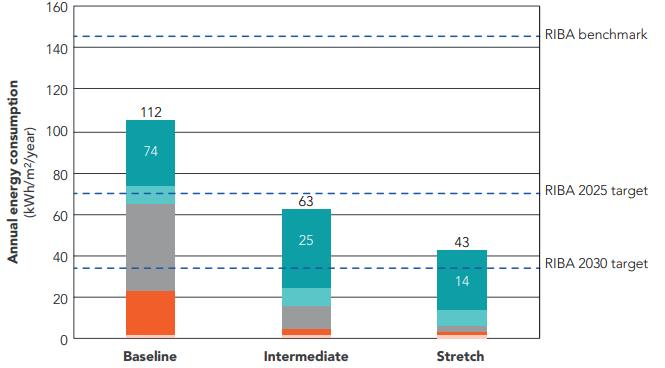
The replacement of concrete with timber structure, along with the removal of a concrete basement a reduction of the total embodied carbon by 74% was achieved, or from 273 to 70 kgCO2e/m2.
Figure2.14Annualoperationalenergyconsumption[29]
Regarding the energy savings, by introducing air source heat pump for domestic hot water and space heating, improved thermal transmittance of windows, reduced air permeability and increased g-value, the energy requirements of the building can decrease more than 40%.
In the residential building, the cost change of the intermediate model, compared to the baseline are increased by 3.5%, and at the stretch modelthey are increased by 5.3%.
Sustainable Building Design 53
2.8. Sustainableresidentialbuildingsexamples
De Oosterlingen residential buildings
Architect: MVRDV
The development covers 13,950 m2 with 144 homes, shops, entertainment etc. The design involves seven sustainable residentialbuildings in Amsterdam The roofs of the lower buildings have urban gardens and a rooftop forest. These green implementations generate very low emissions, achieving a holistic sustainable approach. The design of the masterplan is based on a human-centered approach, meaning that walking routes promote gatherings and stimulate sense of community.
The buildings have varying roof shapes and façades of wood, glass, recycled brick, and biobased composite. One of the building is planned to be made of rammed earth, another should have a completely green facade providing nesting boxes for birds etc[33]
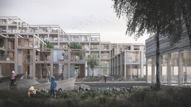
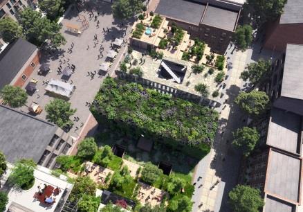
Figure2.15Residentialbuildingsdevelopment
UN17 village, Copenhagen
Architect: Lendager Group and Årstiderne Arkitekter
The development, which is won on a competition, is planned for 400homes in Copenhagen and has apartments, co-living spaces and senior accommodation The area 35,000 m2 is planned to be constructed by using recycled concrete, wood and glass, as wellas upcycled windows. The designers intend to meet allof the 17 UN's Sustainable Development Goals (SDGs) using sustainable resources and creating healthy, social communities[34].
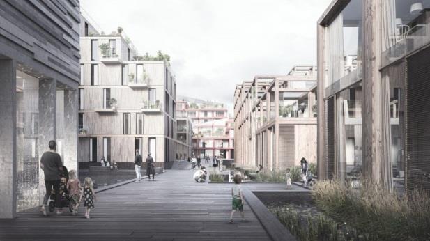
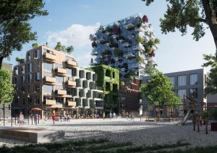
Sustainable Building Design 54
Figure2.16UN17village[34]
Caterpillar house, California
Architect: Feldman Architecture
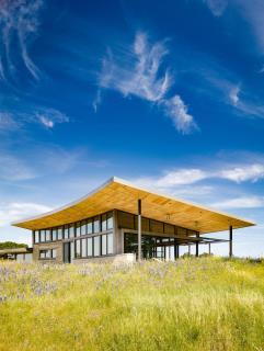
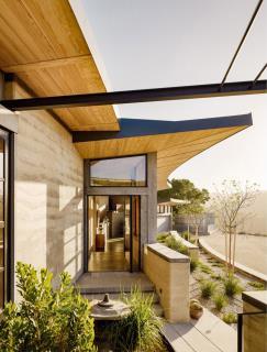
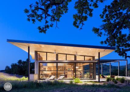
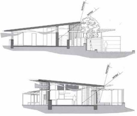
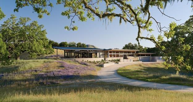
Certification: LEEDPlatinum
The building has a low volume with a horizontal layout. The open plan creates link between the interior and the surroundings. The design of the passive heating and cooling systems are based on south facing high performance glazed areas, natural ventilation and operable shading. Local materials are used, such as excavated earth was repurposed for the construction of the walls, which act as a thermal mass, supporting the interior comfort regulation and reducing the temperature fluctuations. Three tanks close to the home proudly store rainwater and provide all of the property’s irrigation needs. Integrated photovoltaic panels enable the house to produce all ofits own energy requirements.
Multifamily house in Brdo/Ljubljana
Architects: prof. Ales Vodopivec, prof. TadejGlazar, prof. Janez Kozelj, prof. JurijKobe
The buildings` underground garage is made of reinforced concrete, same with the groundfloor and 2 stories, while the remaining 3 stories are made of wooden structure of laminated panels. The thermal transmittance of the facade wall is U = 0,15 W/m²K. The windows are wooden/aluminum, triple-glazed with low-e and argon filled. The glass
Sustainable Building Design 55
Figure2.17LEEDPlatinumresidentialbuilding13
13 https://feldmanarchitecture.com/project/caterpillar-house/
performance is Ug = 0,50 W/(m²K), and the whole window is Uw = 0,68 W/(m²K) with sound insulation of Rw 36 dB and g-value: 0,5.
a) exterior view[35] b)structure of the building[36]
Figure2.18 MultifamilyhouseinBrdo/Ljubljana
The building is Passivhaus certified having RAL installation standard with three-level sealing. The building has a flat roof consisting 36 cm rock wool and 5 cm XPS. The air tightness of the building envelope is n50 = 0,6 /h. The ventilation of the building ismechanical with heat recovery 0,84and naturalventilation is used with hygro-sensible fans.
Figure2.19MultifamilyhouseinBrdo/Ljubljana[36]
The building as a whole is NZEB with an annual heat demand of maximum 25 kWh/m2a, and the primary energy maximum is 80 kWh/m2a. The buildings energy mix comes more than 50% from renewable sources and the CO2 emission in use is 7kg/m2.a.
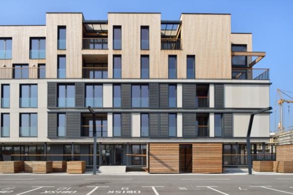
Housing in Bordeaux
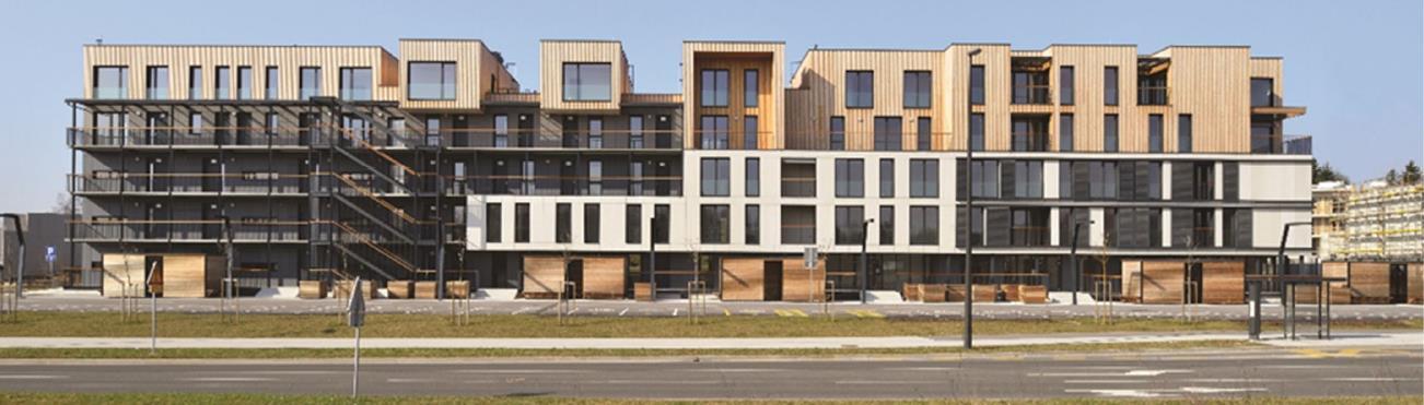
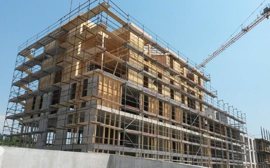
Architect: Lacaton-Vassal
The studio of Lacaton-Vassal utilize the benefits of winter gardens, indoor thermal conditions controlled by geotextiles, adapted structures and nets. They intend to ‘take advantage of the outdoor conditions...manage them and transform them: the opposite attitude from an insulated space that defends itself from climate’ Their residential are applied in various climates ranging from temperate to cold with warm seasons.
Sustainable Building Design 56
Figure2.21Bordeauxbuildingwintergarden[26]
In their project for a social housing complex in Bordeaux they renovate the existing building by adding an external layer of winter gardens in front of the existing structure. The unheated space is considered as a as part of the indoors, and as a buffer zone. In front of the indoor glass, a thermal curtain with a U=1.0 W/m2K intends to provide certain level of insulation, where as its back is made of aluminum, in order to reflect the solar insolation in summer days. In front of the the winter garden glass, a permeable geotextile screen made of aluminum and polyolefin can be used to control solar access or privacy. The interior surfaces ofthe winter gardens are exposed concrete to take advantage of its thermalmass.
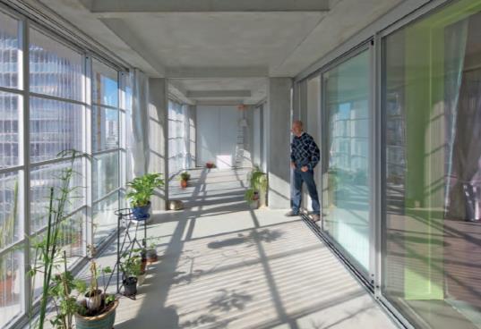
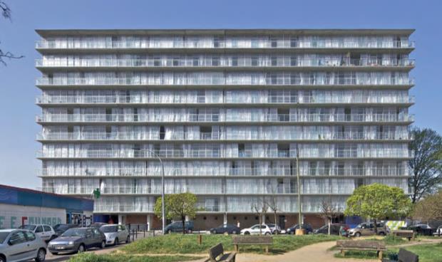
In terms of natural ventilation, the winter gardens reduce the wind pressure on the façade and the air infiltration, while a small opening in the cold period enables intake of fresh air which is pre-warmed. Also the winter gardens contribute to noise reduction. The monitoring of the comfort levels showed that the living room is in comfortable zone 75% ofthe time and the bedrooms 61%. The winter garden has comfortable daytime temperatures
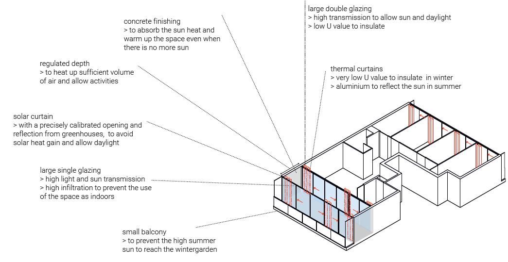
Sustainable Building Design 57
Figure2.20SocialhousinginBordeaux[37]
during 6 months of the year, while during the other half temperatures depend on solar availability.
Heating demand is low, amounting to 7 kWh/m2 with a setpoint of 19°C (according to French regulations) while it is estimated that with a setpoint of 23°C the energy demand would be around 20.3KWh/m2 .
Sustainable Building Design 58
3SustainableBuildingsdesign
D-r Aleksandar Petrovski, Lepa P. Hristovska, Atanas Petrovski
"the symphony of climate... has not been understood...The sun differs along the curvature of the meridian...In this play many conditions are created which await adequate solutions. It is at this point that an authentic regionalism has its rightful place".
Le Corbusier
Sustainable architecture means design and construction of buildings that use less energy and material resources, create less emissions and waste thus having a positive impact on the environment. Sustainable building design also provides the occupants a comfortable architecture that is functional, efficient and meets their needs
The sustainable design focuses on multitude ofbuilding related aspects, some of which are:
Understanding Place - Sustainable design begins with an thorough understanding of the place, climate and site analysis, needed to determine design practices which can be implemented in the design such as solar orientation of the building, preserving and enhancing the natural environment, integrating the nature in the design etc.
Understanding Natural Processes - Meaning understanding the local natural context while improving it and contributing to its thrive. Green and regenerative buildings are conceived on the analogies of the process in nature where there is no waste. The byproduct of one process is used or reused for other purposes. Such is an example of composting, using rainwater, gray water for ponds irrigation etc.
Understanding Environmental Impact - Sustainable design means having an integral evaluation of the impact the building's design has onto the environment, such as energy performance, embodied energy, toxicity ofthe materials etc.
Integrative Design Processes - Due to the various engineering systems in the building, collaboration is needed between, engineers, consultants and other experts, throughout the design process.
Sustainable Building Design 59
Understanding People - Sustainable design requires strong social analysis and sensitivity towards the habits and needs ofthe buildings` users, the culturaland social context
In the core of the sustainable buildings deign six fundamental principles can be distinguished, such as:
1. Maximizethesitepotential
Taking advantage ofthe sun, wind, topography etc. Microclimate and architecturaldesign have an essentialeffect on the energy performance ofbuildings. Multitude of aspects need to be evaluated such as: buildings` orientation, glazing, use of passive design systems etc. Also the landscaping of the site must be integrated with buildings` design.
2. Sustainablematerials
It is crucial to use sustainable, reusable/recyclable materials and low embodied carbon materials which minimize life-cycle environmentalimpacts such as globalwarming, resource depletion, and toxicity. Also, these materials contribute to improved interior comfort, human health and lower maintenance cost.
3.
Efficientenergyuse
With ever-increasing demand of energy it is essential to design buildings with increased efficiency and to maximize the use of renewable energy sources. It can be achieved by high performance building envelope, efficient passive and active systems in the building for heating, cooling, lighting, appliances etc.
4. Efficientwaterandwastemanagement
Buildings have an impact on the water resources as well. Sustainable buildings should use water efficiently, and reuse or recycle water for on-site use, when feasible. This can be achieved by various systems to reduce, reuse, and treat water; capturing and managing rainwater, greater, waste managementand composting etc.
5.
IndoorEnvironmentalQuality(IAQ)
The indoor environmental quality (IEQ) of a building has a very high impact on occupant health, comfort, and productivity. Sustainable buildings are designed in such a way that they maximize daylighting, have adequate natural ventilation and moisture control, comfortable acousticperformance, materials with low-Volatile OrganicCompounds (VOC) emissions.
6. OperationandMaintenance
Monitoring and optimizing the buildings` operating and it maintenance contribute to its more efficient performance, high quality environments, durability, lower costetc.
Sustainable Building Design 60
In order to meet the forementioned demands, there are two types of design principles, measures and systems which can be used, such as: passive and activesystems.
Passive systems take advantage of natural energy flows, such as the solar and wind energy to regulate the buildings` heating, cooling, daylighting and ventilation demand. Sustainable design that utilizes the local microclimate could lead to up to a 60% reduction of the energy demand. The use of passive heating, passive cooling and daylighting can reduce the energy demand by a another 20%, amounting to 50-80% reduction[38]
Active systems require additional energy for their for operation, as they are mechanical, electrical systems and appliances In order to have a net-zero building or plus-energy building which produces more energy than its needs, highly efficient active technologies should be used In building design, passive technologies should predominate over active ones.
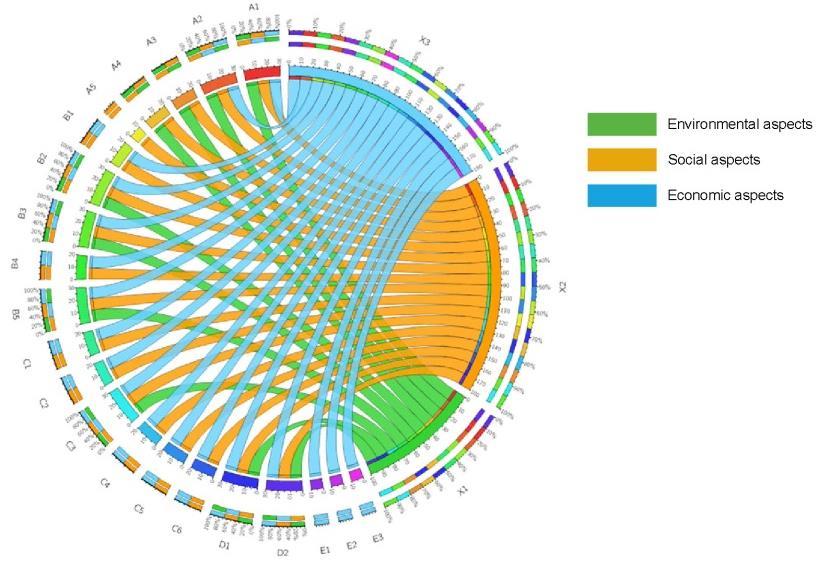
Figure3.1Interrelationofbuildings`designcriteria
Considering the complex and multidisciplinary nature of the sustainability it is necessary to look upon the significance on each design criteria separately in the context of the buildings. Also, all of the design criteria are somewhat interdependent and influence each other. The buildings orientation, form and functional layout can influence the energy performance, daylight quality, construction costs etc. The choice of the materials can influence the buildings` embodied carbon, energy performance, comfort (thermal, acoustic etc.), costs, dimensioning of the mechanical systems etc. In such a complex system of many design criteria it is required to use multi-criteria assessment to inform the architectural design decisions.
In this part we willgo through several architecturaldesign aspects.
Sustainable Building Design 61
3.1. Siteplanning
A site analysis should take into consideration the solar envelope, local wind direction and intensity.
The solar access of the building will depend on the geographical longitude of the building plot, the topography, surrounding buildings and vegetation. The solar access of the site can be investigated using either by:
Physical modeling – 3D site/building model used with a heliodon or solar chart. Digital modeling – 3D simulation of sun and shadows on structures, vegetation and developments; configuration of a solar envelope as a buildable volume that will not shade adjacent sites.
Solar envelope
The solar envelope is primary method of site planning for passive heating and it is defined as the boundaries of a three-dimensional volume, on the site, having unobstructed access to the sun during a certain time period over the year It is required to keep the south elevation free from obstructions in the northern hemisphere (NH) and the north elevation free in the southern hemisphere (SH).
The solar envelope means that a portion of the site, represented by a three-dimensional volume, has access to the sun so that passive heating systems can function properly. Additionally it doesn’t obstruct near buildings from sun access. The simple rule governing layout of buildings to maximize the benefits ofsunlight can be taken as follows: no obstructions within a 30degree angle from the south–north elevation. no other building obstructing the window within an elevation angle of 25degrees.
Figure3.2Unobstructedaccesstosunlight
The solar envelope is determined from the volume created by the range of sun movement during the operating schedule of a building over the year. For example, suppose a building has an operating schedule of 0800 to 1700h year-round, and the site constraints allow the sun in during the winter between 0900h and 1500h, and in the summer between 0700h and 1700h. The sun locations in winter (December 21st) and summer (June 21st) can be plotted for these times and converted to a three dimensional volume. This establishes the solar envelope within which the building is designed.
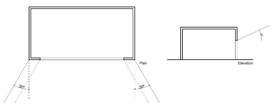
Sustainable Building Design 62
a) roofprofiling[39] b) building volume profiling[40]
Figure3.3Establishingsolarenvelopeboundaries
The solar envelope method enables architects and planners to take into account required direct solar access on existing surrounding facades during the schematic design phase by determining the maximum height and massing that the designed buildings cannot exceed in order to guarantee the required solar rights on surrounding buildings. The solar envelope method is useful tool to be used in the urban planning in order to properly orientate and shape the buildings and the urban blocks.
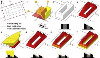
Figure3.4Solarenvelopeformodelingurbanblocks[40]
The inputs for the solar envelope calculation are the: solar azimuth and elevation angle at the required hours; the borders ofthe plot of the new development; the distance ofsurrounding buildings; and, the height ofthe shadow line on surrounding facades.
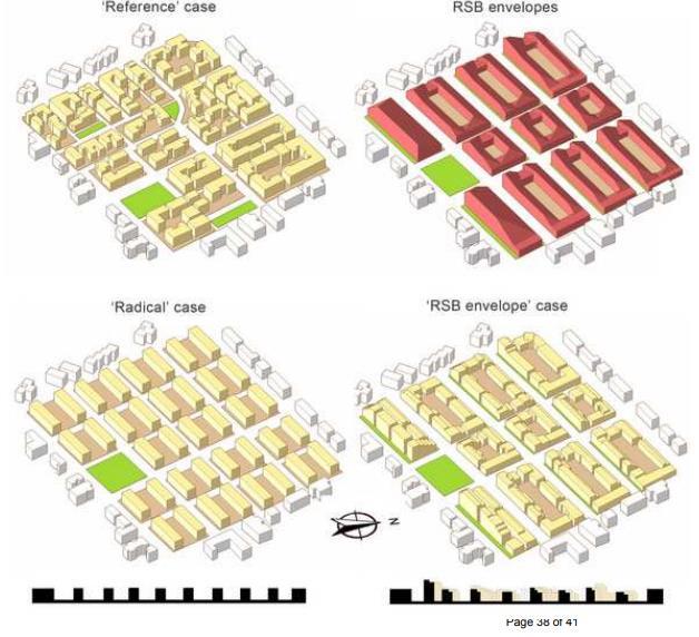
Depending on the plot shape and surrounding building distances, the solar envelope has a variable, irregular pyramidal shape In Figure 3.5b, the buildings` edges are sloped in order to provide solar insolation of the surrouding buildings. Parametric tools can be used in order to properly mass the buildings` volume, Figure 3.6, 3.7

Sustainable Building Design 63
a) designed with conventionaltools b) designed with parametrictools
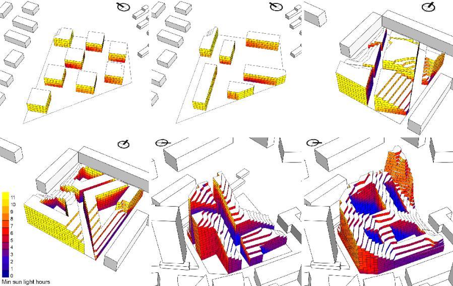
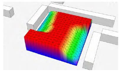
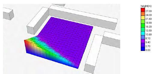
Figure3.5Buildingheightdesignedwithsolarenvelope[26]
Figure3.6Analysisoftheminimumquantityofdirectsunlightperdayduringrequiredperiod[41]
Figure3.7Buildingshapingbythemethodofsolarenvelope[42]
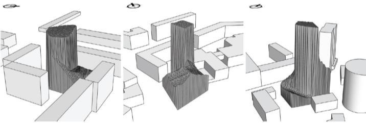
Winds and landscaping
In the site planning phase, local wind and breezes direction and intensity should be analyzed In case of stronger winds in the winter period, wind breaks and wind shelter should be considered Wind shelter can be provided by several means: other buildings, natural vegetation or artificial windbreaks. Providing wind shelter however, may be in conflict with the desire to provide solar access.
Table3.1Shelterbeltsandreductionofwindspeed[43]
Sustainable Building Design 64
Distance from belt in belt height (H)
Percentage reduction in wind speed 2 5 10 15
60 40 20 10
For passive solar buildings facing south, good solar access for winter sun is maintained if the shelter is at least four times the height of the building distant from it for latitudes up to 55° north–south and five times the height of the building distant up to 60° north[43]. Shelterbelts protecting open spaces will be effective at reducing wind speed by the amounts shown in Table 3.1.
Landscaping can contribute to improved buildings` performance. Vegetation contributes to the reduction of the ambient temperature and limiting the heat island effect around buildings, thus reducing the cooling load. It protects the building from sun, wind and precipitation. Deciduous trees provide cooling shade in the summer and after shedding their leaves allow for warm sun to enter the building in the winter.
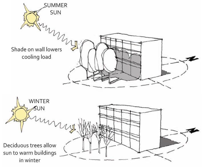
Figure3.8Landscapingforimprovingbuildingsperformance[44]
3.2. Buildingorientation
As we know, the sun`s heat varies according to regions and seasons. During cold periods the suns radiation is welcomed inside the building and the building should be positioned to receive as much radiation as possible. In periods of excessive heat the orientation of the building should limit the undesirable excess solar heat. In terms of a bioclimatic chart these two conditions are named as underheated (winter) and overheated (summer) period of the year. The most desirable orientation of the building should provide maximum penetration of the solar radiation in the underheated period, while reducing the solar radiation impact in the overheated period.
Sustainable Building Design 65
The buildings in the northern latitudes, where the air is generally cool, should be oriented to receive maximum amount of solar insolation. In the south latitudes, characterized with warmer air, the building should be oriented to avoid the solar insolation and utilize the cooling localbreezes.
In Figure 3.9a, the insolation levels are shown in the underheated period in the cold months, where the maximum levels are east of south. In the hot months, in the overheated period, Figure 3.9b the biggest sun gain is far to the west of south. The solution for the buildings` orientation is to position the main facade to the largest winter gains, while the buildings` shorter side facade is being perpendicular to the angle of the undesirable summer sun in the overheated period.
a) underheated period b) overheated period c) compromise orientation to 25° east of south
Figure3.9Insolationlevelsandorientation[45]
A comparison of optimal building orientation relative to four climate types is given for buildings with predominantly one orientation.
In the cool and temperate regions the optimal orientation is south or inclination of 20° to westor 40° towards east, with 12° to the eastare optimal.
In the temperate region the inclination can be 15° and up to 45° to the west and east respectively, with 17.5° to the east are optimal.
In the hot-arid region the orientation should be towards south with inclination of up to 35°, with 25° towards eastbeing an optimum.
In the hot-humid zone the orientation should be perpendicular to the axis of the overheated period, meaning the building can have an inclination of 5° to the west and 15° towards east, with 5° to the eastare optimal
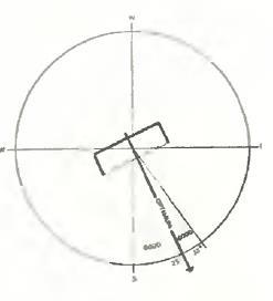
Buildings with apartments back-to-back are unsuitable for southern latitudes and should be replaced by "through" typology of buildings where a same apartment has two opposite orientations. Such bilateral typologies have a large positioning range in the cool and temperate zones. With the rotation of the axis towards the west, the heat distribution on the sides will be equalized, but the west side will receive less sunlight. At most easterly axis positions, the west side should be protected from summer radiation. The back-to-back building type is unsuitable for more southerly latitudes and should be replaced by the through type ofbilateralbuildings.
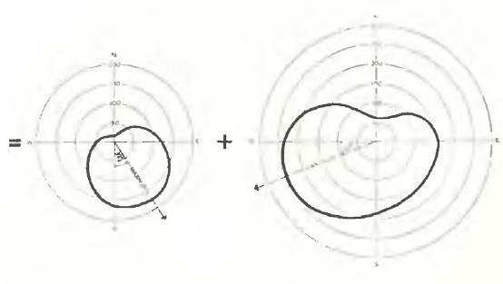
Sustainable Building Design 66
a)unilateralbuilding type b) back-to-back bilateral type c) bilateralthrough type
Figure3.10Buildingorientationrelativetoclimate[45]
Choosing optimal building orientation can be assisted by using software tools. An efficient tool is Climate Consultant which can calculate the effectiveness of passive and active building design strategies for specific geographic and climatic area. The building occupation hours are plotted on a psychrometric chart showing the dry-bulb, wet-bulb temperature and humidity ratio. The comfortable range of these parameters is shown within the rectangles. This chart can help understand the differences in creating a comfortable climate during the summer and winter period as different design strategies are needed for each of them. The Climate Consultant shows possible design strategies that can contribute to improvement ofthe comfort and the user can choose which one of them are preferable for the design. The tool calculates how much of the chosen design strategy contributes to the comfortable levels shown in percentage of occupancy time. Climate consultant can also offer to show best strategies for the design, so the architects can focus on those strategies with largestimpact and benefit for buildings` sustainability
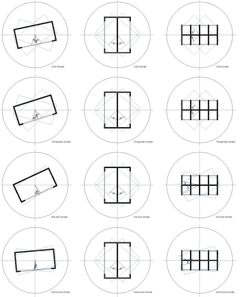
Sustainable Building Design 67
Figure3.11PsychrometricchartbyClimateconsultant
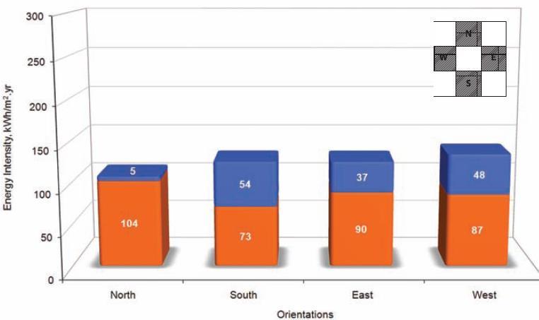
The buildings` orientation, especially its transparent surfaces have significant impact onto its energy performance due to the different solar insolation levels. Therefore it is very important to correctly determine the dimension of the glazed areas relative to the buildings 'orientation Also, appropriate solar control should be designed for the overheated period by shading devices, greenery etc. On a case study it is shown how the orientation of the apartments influences their heating and cooling demand. The apartments to the north have highest heating and lowest cooling demand. The lowest heating demand have the south oriented apartments. The cooling demand of south facing apartments can be decreased by design strategies such as: shading, buffer spaces, double facades, thermalmass etc.
Figure3.12Heatingandcoolingloadofappartmentsrelativetotheorientation[44]
Tools for analysis
Early design decisions can make a significant impact on the buildings` sustainability. Sustainable analysis tools assist the architects and engineers to make informed decisions early in the design process affecting the efficiency and sustainable performance of a building design. Nowadays there are multitude of sustainability analysis tools, such as DesignBuilder, EnergyPlus, Autodesk Revit, Green Building Studio, Rhinoceros and Diva,
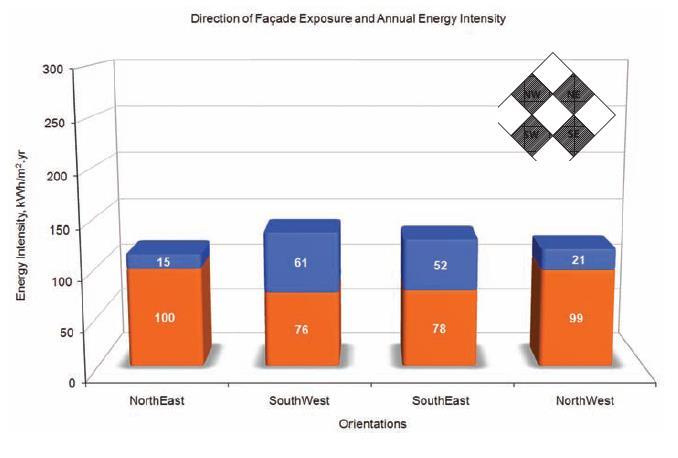
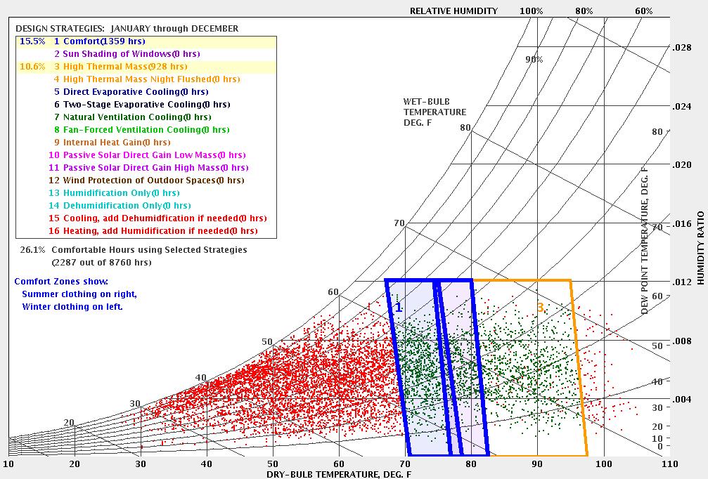
Sustainable Building Design 68
Grashopper plugins (LadyBug, Honeybee etc.), Ecotect and others, help engineers to promptly assess various design aspects and give them the ability to iterate different design proposals in order to choose the optimal sustainable design. Within Rhinoceros/Grasshopper or Dynamo environment, multitude of plugins are available for environmental analysis. Ladybug plugin provides climate analysis with visual representation, Honeybee enables energy performance analysis, daylight and comfort modeling of the building. The plugin Butterfly can be used for analysis of indoor and outdoor airflow, buoyancy calculation, indoor and outdoor comfort as well as the HVAC system, while Dragonfly empowers designers to performance urban modeling and analysis.
a) Shade and solar analysis - Ecotect (above) b) Ladybug plugins (below)14
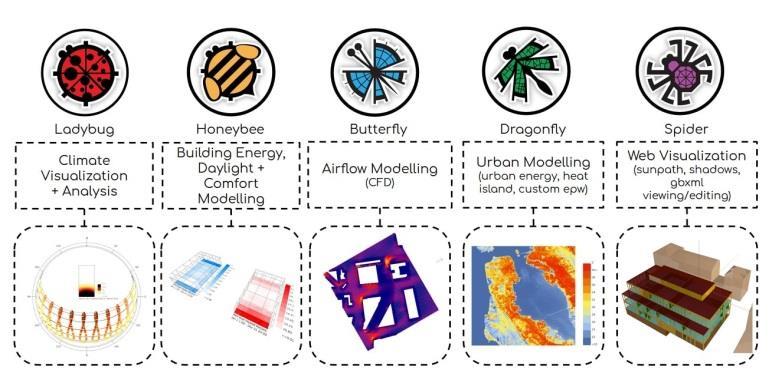
Figure3.13Softwaretoolsforenvironmentalanalysis
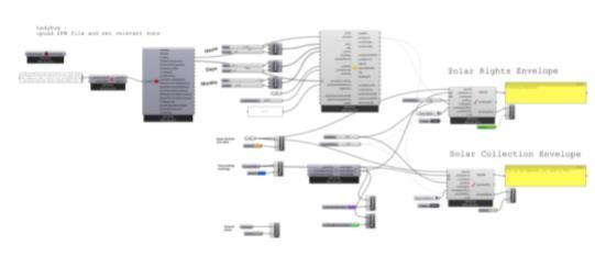
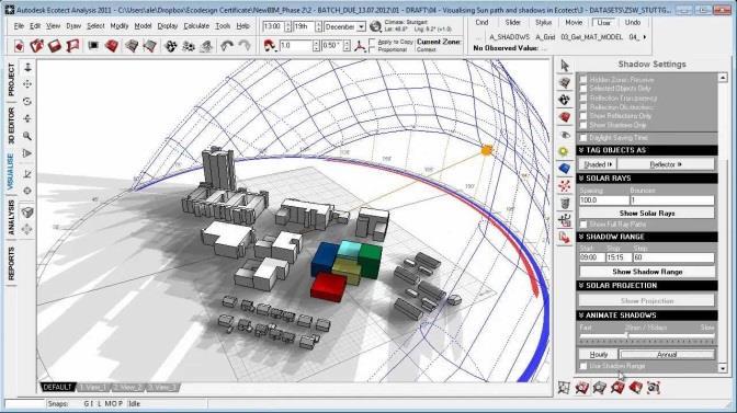
3.3. Buildingform
A building’s from (ratio of its plot size, volume and overall geometry) has a significant impact on a building’s functionality, energy efficiency, carbon efficiency and natural lighting. Designing a building with as much as lower envelope (facade, roof and floor) surface area is an approach to improve buildings efficiency, reducing the thermal transfer, lower the embodied energy and environmental impacts caused by the materials required to construct the envelope. Hence, some building forms are inherently more efficient than others, regardless ofthe materialbeing used to realize them
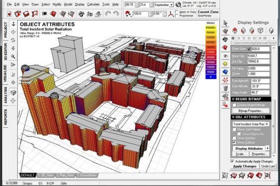
Sustainable Building Design 69
14 ladybug.tools
The solar insolation and regional thermal stress influence the form of the building. In colder climates, the buildings` should have a more compact form, while in regions with heavy radiation impact, the buildings should have elongated shape with an east-west axis.
In the northern hemisphere, the buildings` south facade can receive almost twice as much solar radiation in winter than in summer.This ratio can be even larger in the southern latitude, resulting in a one to 4 ratio. On the other hand, the east and west facade can receive up to 2.5 times more amount of solar insolation in summer than in winter. For comparison, in summer the east and west facades can receive 2 to 3 times more insolation than the south facade. The rooffacade receives the largestamount ofinsolation compared to the others.
The aspect of building form can be described by various parameters some of which offer better description of the interdependent of the form and buildings` performance. These parameters are:
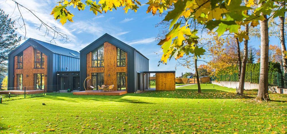
plan ratio
compactness
form factor
Figure3.14Buildingwithcompactform
Plan ratio
Optimal plan ratio of a residential building is recommended relative to the climate zone of the building[45]. The general rule is that the square house is not the optimum plan ratio in any location, rather an elongated form with an axis ofthe elongation to be east-west. The ratio of the length of the building is given for the summer and winter period as a near optimalratio, with a degree of flexibility, such as:
In cool climate the winter optimal plan ratio is 1:1.1 and the summer is 1:1.4.
In temperate climate, the winter optimal plan ratio is 1:1.56 and with summer optimal ratio is 1:1.6. The ratio can be up to 1:2.4.
Sustainable Building Design 70
15
15 https://modelur.com/use-form-factor-to-reduce-energy-consumption-of-buildings/
In hot-arid climate the the summer optimum is 1:1.26, and as the summer stresses are nearly eight times as large as the winter ones, the optimum plan ratio can be 1:1.3 up to 1:1.6.
In hot humid climate the winter optimal plan ratio is 1:1.7 while the summer optimal ratio is 1:2.69, up to 1:3.
Figure3.15Buildingsratiorelativetoclimaticcontext
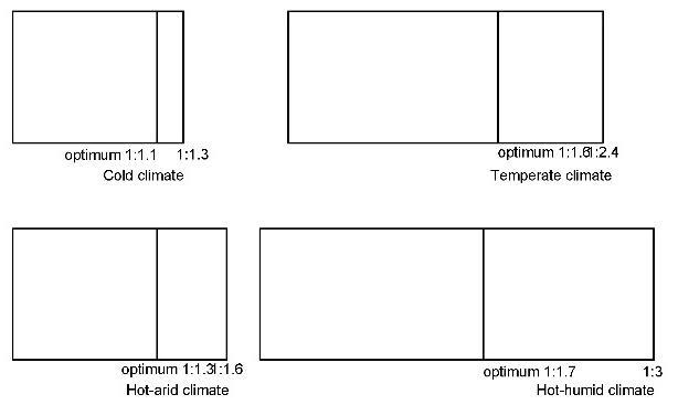
In larger buildings choosing the optimal orientation and form can be more limited due to plot size, surrounding buildings, as well as the spatial and programmatic organization of the building itselfetc. Olgyay lays out generalprinciples for larger buildings, such as:
In cool climates, the compact forms are preferable with a "back-to-back" buildings plans on the north-south axis due to their relatively dense cubature. The environmentalpressure favors higher buildings in this type of climate.
In the temperate zone there is a freedom in form due to the more favorable climate conditions, and the buildings elongated to the east-westaxis are preferable.
In the hot-arid zone, massive shapes are more advantageous, with cubical form or elongated towards the east-westaxis. High buildings are preferable.
In the hot-humid zone the buildings should be elongate to the east-westaxis.
Orientation and sun exposure
The solar insolation intensity vary according to the buildings orientation. In Figure below two positions of the building are shown. In the south position, facade A, faced south, has the largest solar insolation in March and October which are beneficial periods for passive solar warming of the interior, as the heating season ends and begins, respectively. During the summer the insolation decreases on the south facade which lowers the energy demand for cooling. Thus the facade has optimalorientation towards south or up to 20° to the east.
Sustainable Building Design 71
0° to south
20° towards east
Figure3.16Amountofsolarradiationappliedonafacaderelativetoitsorientation[46]
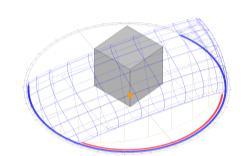
The influence of the orientation and the form factor is shown in four models of a small residential building. The models form factor varies from 1:1, 1:2. 1:3 and 1:4, while maintaining the total area of 108 m2 . The energy consumption is shown with glazing varying from 12-40% ofthe facade surface.
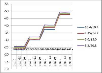
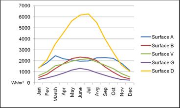
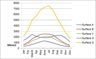
Figure3.17Varyingtheformfactorinsmallresidentialbuilding[46]
Compactness
The optimal building form can also be express in terms of buildings compactness. Compactness is defined as the surface to volume ratio of the total external surface area (A) of a building (the total heat loss area including walls, roof, floor on ground and openings) divided by the buildings internal volume (V)
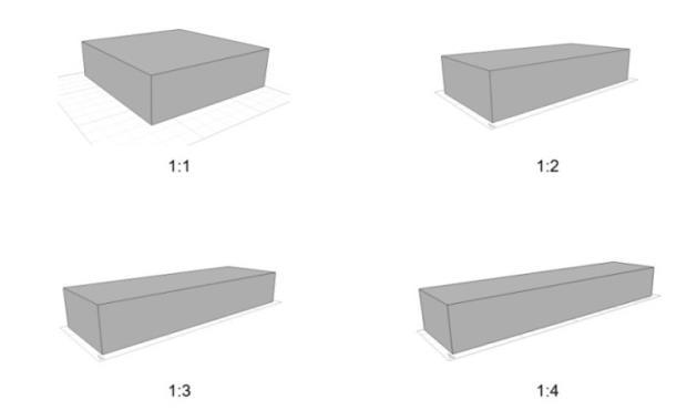
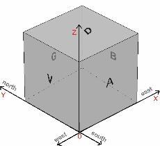
Compactness= A/V (m2/m3)
This ratio, between the external surface area and the internal volume of a building, has a considerable influence on the overall energy demand. Building forms with a lower S/V ratio have higher compactness, meaning that a lower value indicates a more compact, efficient building.
Sustainable Building Design 72
a) reducing S/V ratio
b) reduce perimeter to area ratio
Figure3.18Compactnessofform
The size of a building influences the A/V ratio. Small buildings which have an identical form have higher A/V ratios as compared to larger buildings. Hence, it is of high importance to design small detached buildings with a very compact form. On the other hand, larger buildings provide the architects greater freedom in shaping the building, which can have more complex geometries. This aspect, stresses the decisions the architects make in the early design choices, regarding the shape of the building, the form and massing, which all directly influence on the buildings energy efficiency. A building can have a fairly simple massing, but if it has a lot of recesses or protrusions in the thermal envelope, the surface areas soon add up. As the surface of buildings` envelope decreases, there is less surface area for heat to escape through. In the Figure below, the influence of form and size on the A/V ratio is shown. A favorable compactness ratio can be considered where the A/V ratio is 0.7m²/ m³.
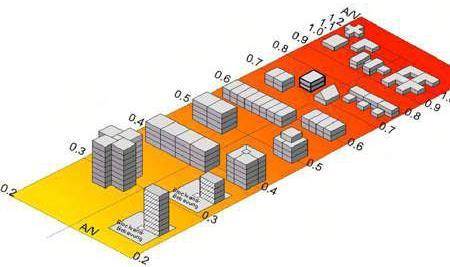
16
Figure3.19Compactnessratios
All of the forms can be designed to meet Passivhaus criteria, but the compactness has an effect on the amount of insulation needed to achieve the same U-value. Hence, if a building has a form factor of 1.0, a lower U-value of the envelope would be required. Therefore instead of the recommended U=0.15 W/m²K the building envelope may need to have approximaive U value of 0.08-0.10W/m²K.
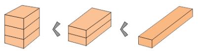
Sustainable Building Design 73
16 https://thefifthestate.com.au
Recommendations are given for Surface to Volume Ratio for a typical single family house to be between 0.8 – 1.0, while others recommend it to be below ≤ 0.8 or even 0.517
Form factor
The Form Factor (F) is another useful parameter which describes the relationship between the external surface area (A) and the internal Net Floor Area (NFA). This allows useful comparisons ofthe efficiency of the building form relative to the useful floor area.
F= A/NFA (m2/m2)
Sustainable buildings should aim to achieve Form Factor value of three or less. If the form factor is over three, achieving the criteria of the Passivhaus Standard becomes challenging. It is can be difficult to achieve a form factor below 2.5 on a stand-alone residential building. However, taller buildings, can more easily achieve a form factor lower than 118
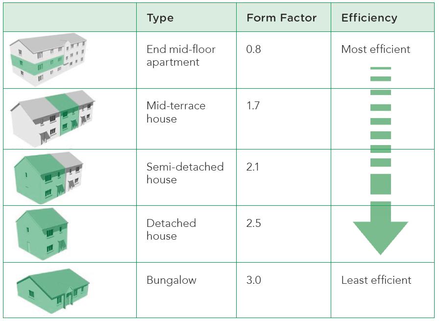
Figure3.20FormFactorandbuildingtype
Also, the complexity of the form can have an impact on increasing the thermal bridges which needed to be solved with the architectural design and increasing the shading- factors that can have an impact on the annualenergy balance.
Another aspect to bear in mind is that the change of the shape of the building and its Form Factor influences the occurrence of thermal bridges. Buildings with higher Form Factor have more thermalbridging which needs to be solved by appropriate detailing.
17 https://www.forum-holzbau.com/pdf/ihf09_Lylykangas.pdf
18 https://www.greenspec.co.uk/building-design/heat-loss-form-factor/
Sustainable Building Design 74
Increase of surface area by 10% and 20%, can approximately increase the need for thermal insulation by 2 cm and 4 cm respectively in colder climate. However, in warm climates this may not be an issue if other cooling strategies are designed in the building.
The impact of the Form Factor is shown in Figure below. All of the buildings have the same size, however the energy demand increases more than twice in the worst case, compared to the bestperforming case.
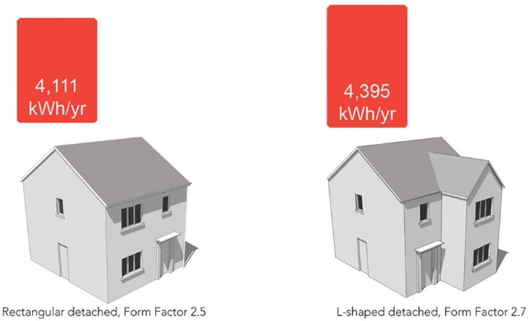
Figure3.21SpaceheatingenergydemandforsamesizebuildingsandvaryingFormFactor
Similarly, the impact of the Form Factor onto the heating energy demand is shown on a case study building presented in Figure below.
Figure3.22ImpactofFormFactoronheatingenergydemand
The impact of various design decisions onto the buildings performance is shown in the following Figure.
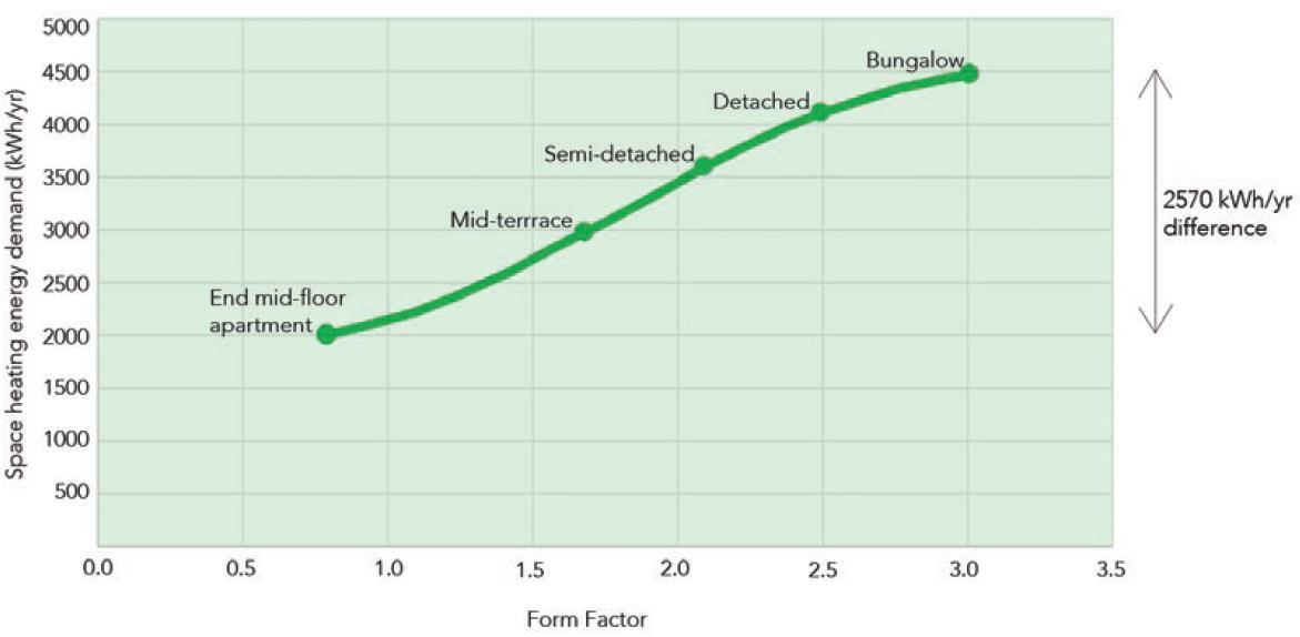
Sustainable Building Design 75
Figure3.23Impactofdesignsolutionsontotheenergyconsumption
The positioning and size of the loggias and balconies impacts the buildings` form factor, shadowed surfaces due to recess of the envelope and the energy performance. It can be seen that the balconies are more efficient solution, however consideration should be given to possible thermal bridging that may occur in this case due to protrusion of the slab through the buildings` envelope.
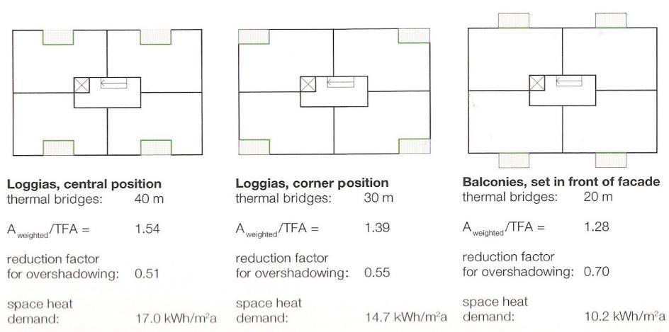
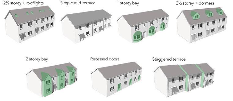
Figure3.24Impactofbalconiesand loggiasonenergyperformance[47]
Achieving higher energy performing building by lower Form Factor, doesn't mean that the buildings` design shall be dull, nor it limits the architects in their creativity. Inefficient features of the buildings` design can be replaced by suitable alternatives which are architecturally compelling. For example, the decrease of building performance due to unfavorable orientation can be compensated with adjustment of the Form Factor.
Also it can be argued that the Form Factor can be even more impactful regarding energy consumption of buildings, compared to the aspect of orientation and utilizing solar gains. However, building which is specifically designed for utilizing solar radiation has undeniably strong benefits and improved energy performance with extremely low consumption as we shallsee in the next chapter.
Considering the large impact of the Form Factor on the energy performance of buildings, analysis of different design proposals should be performed in the early design stage.
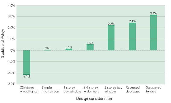
Sustainable Building Design 76
Comparison of compactness and form factor
When compared, the surface to volume ratio (compactness) and Form Factor, it can be concluded that the latter one, the Form Factor is more accurate when comparing buildings with different heights19. When the height of the space increases, the volume and the heating energy demand grow. Surface to Volume ratio falsely indicates that the building got more compact and therefore needs less energy than lower building. Heat Loss Form Factor
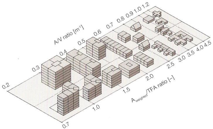
Figure3.25Comparisonbetweenthesurfacetovolumeandformfactor20
Another comparison is given in the following Figures in terms of measurement scale and buildings` size.
Figure3.26Comparisonofcompactnessandformfactorrations[47] 1919 https://www.forum-holzbau.com/pdf/ihf09_Lylykangas.pdf 20 https://modelur.com/use-form-factor-to-reduce-energy-consumption-of-buildings/
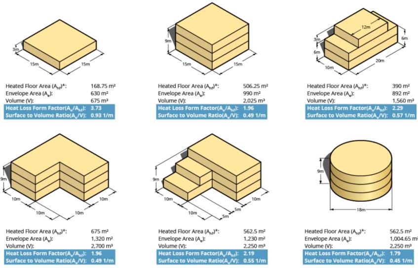
Sustainable Building Design 77
Correlation between the U value and the Form Factor
In the Figure below the corellation between the U-value vs Heat Loss Form Factor is shown.
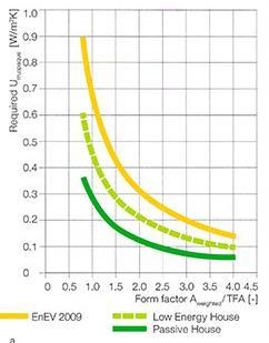
In the cases where the Form Factor is more than 3, the U value doesnt change significantly. However, when the form factor is below 2.5, the changes in U values can be quie significant and exponential. This reflects to the concept of `superinsulating` the Passivhaus buildings which doesntneed bo always the case, but it should be calculated accordingly21
Urban form
In that regard, layout for the urban block in the cities are proposed relative to the climate, where[45]:
In a cool environment the layout should protect the buildings from the cold wind. The buildings should be closely grouped to have less exposed surface to heat loss and spaced properly to utilize the benefit of the solar insolation for heating. This layout is so called, an insolated dense layout.
In the temperate zone, the plans are open, having the possibilities for free arrangements, intertwining the nature and the buildings.
In the hot-arid zone the buildings can be grouped together and with the gardens can provide shade and achieve defense in volume. The buildings can be organized around closed courtyards, which act as cooling wells.
In the hot-humid areas the buildings can be freely elongated. Buildings can be separated in order to utilize the air movement.
Sustainable Building Design 78
Figure3.27CorrelationbetweentheFormFactorandUvalue[47]
21 https://www.greenspec.co.uk/building-design/heat-loss-form-factor/
Therefore, the buildings form and the layout of the urban matrix can influence sustainability of the urban block and cities. Such impact on an example of buildings in Mediterranean climate is shown in Figure below.
Figure3.28Heatingandcoolingdemandrelativetotheformofthebuildingsandurbanblock[48]
The building form influences the quality of the daylight and use of artificial lighting in the interior. An elongated building can have as much as a 15-25% reduction in energy use over a compact building of the same size, due to its greater ability to use daylight. The following guidelines for buildings forms in relation to daylight can be met:
Narrow buildings use less energy in total as they can be more effectively day lit, leading to a reduction in electrical load, which outweighs any slight increase in fabric losses due to a large façade area.
Courtyard buildings do not perform as well as shallow buildings since they have less daylight and naturalventilation.
Atrium buildings perform in a similar way as courtyard buildings, although the ventilation is better than in courtyards (due to stack effects). There may be a need to include mechanical ventilation in the upper floors due to the low stack pressures at higher levels.
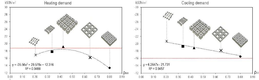
3.4. Buildinglayout
Independent of the building concept, an optimum arrangement of the layout can result in 10 to 20% energy savings
The orientation of buildings with same shape but differently arranged living areas and glass surfaces will require different orientations to take the best advantage of the solar insolation. There are many recommendations for room orientation. Recommendations for residential buildings above 35° latitude are given in Table 3.2. The position of the spaces in residential building is proposed according to their optimal orientation[45]. For determining the orientation the occupancy hours of the spaces should be considered. Also, another factor of the orientation is the germicidal sanitization effect ofthe solar radiation.
Sustainable Building Design 79
Table3.2Orientationofresidentialspaces[45]
space/ orientation north northeast east southeast south southwest west northwest bedroom ■ ■ ■ ■ ■ ■ living ■ ■ ■ ■ dining ■ ■ ■ ■ ■ kitchen ■ ■ ■ ■ library ■ ■ ■ laundry ■ ■ ■ playroom ■ ■ ■ ■ bathroom ■ ■ ■ ■ ■ ■ ■ ■ utility ■ ■ ■ garage ■ ■ ■ ■ ■ ■ ■ ■ workshop ■ ■ ■ terraces ■ ■ ■ ■ ■ sun porch ■ ■ ■ ■
It is recommendable to locate cooling dominant spaces on the north or in the center of the building away from solar gain. The heating dominant spaces should be towards the south or west, avoiding over-exposure to west solar radiation. Therefore, building spaces such as living rooms, bedrooms and similar need to be placed in the most beneficial orientation, such as south, east or west. Spaces that don't require as much thermal comfort, such as utility spaces should be placed in the north area ofthe building or in the middle ofthe floor plan
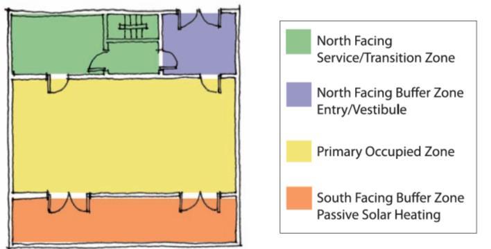
Figure3.29Functionallayoutrelativetothe
orientation[44]
Also, buffer spaces can be used to the south, such as double facades, Trombe walls or greenspace to improve the indoor thermal comfort by regulating the transmission of solar heat to the interior, by storing it and releasing it when necessary. Thermal storage can be provided in the thermal mass of the floor and/or walls of the sunspace structure itself. Stored heat can either reach the building passively through the walls between the sunspace and the interior, or be distributed by an active mechanicalsystem.
Sustainable Building Design 80
a) summer performance b) winter performance
Figure3.30Doublefacadeasbufferspace[44]
During the winter, the buffer spaces create an insulation layer in front of the buildings envelope, decreasing the heat loss between the outdoors and the indoor conditioned space. An example of a buffer space is shown in Figure 3.17. where the double facades prevents the solar insolation from penetrating in the building, while providing natural ventilation and dissipation of the internal heat outside the building. During the winter period, the double facade enables the solar radiation to warm the interior of the building and the thermal mass in the floors/walls. The absorbed heat is then released at night in the interior and decreases the energy need for heating the space.
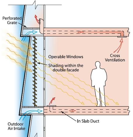
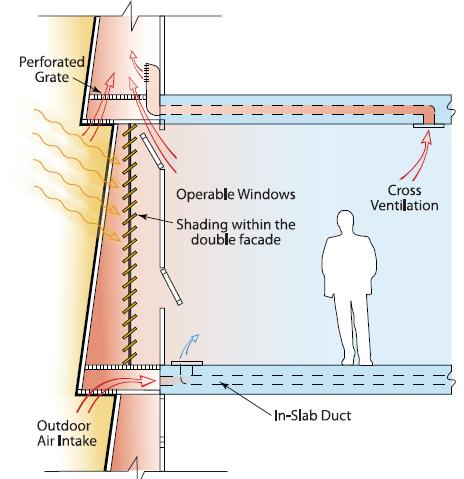
Designing balcony buffer spaces in apartment building contribute to lowering the heating and cooling demand. From Figure 3.31 the contribution of the buffer spaces is evident, relative to the orientation of the apartment. The left column shows the heating and cooling energy demand in a building without balcony buffer space, while the right column shows the performance with a balcony buffer space.
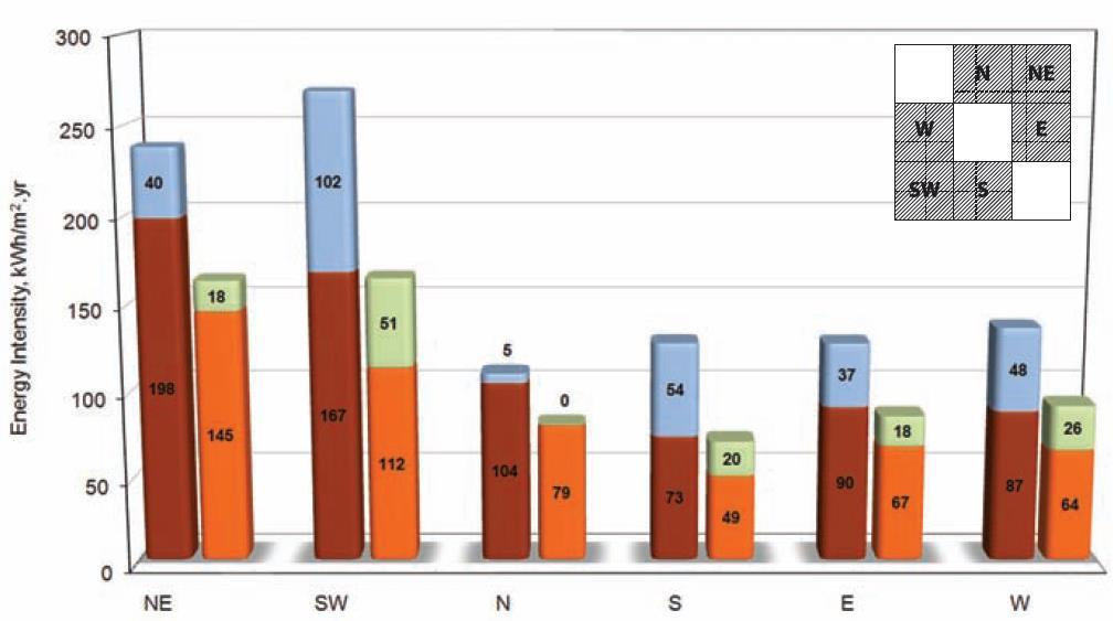
Sustainable Building Design 81
Figure3 31Influenceofbufferspaceonannualenergydemand[44]
3.5. Climatedesignguidelines
During the design process architects and engineers should take into consideration the local climate and weather records, local experience and building related knowledge. Within a given climatic area, the specific characteristics of the location can vary substantially and each demands thorough micro-climate analysis.
The aspects needed to be assessed that affect the micro-climate are: elevation, incident solar radiation, wind, shade ofadjacent buildings, surrounding topographicshades (mountains etc.), water and wetlands, vegetation etc.
There are several climate classifications and the most widely used general climate classification is the Köppen-Geiger system. The United States has the following climatic areas: cold/very cold, mixed-humid, hot-humid, hot-dry/mixed-dry and marine.
In Europe there are 35 climate areas aggregated into six classes, such as: polar, bo-real, temperate continental, temperate transitional, temperate oceanic and medinerranean, Figure 3.1.
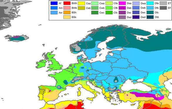
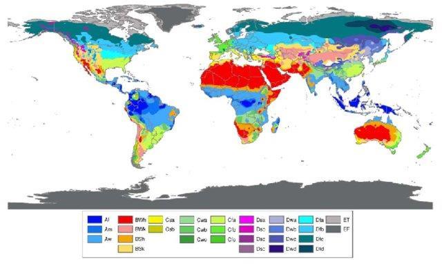
Coldclimatedesignguidelines
This climate is characterized as cold, without dry season and with cold summer. It is classified as Dfc according to the Köppen classification. Some European cities in this zone are: Helsinki, Stockholm, Riga, Gdansk etc. Recommendations for buildings` design in this climate are: Buildingtype - compact buildings are preferred, such as row houses, due to lesser heat loss. Form - In cool climate the winter optimalform is 1:1.1 and the summer is 1:1.4.
Sustainable Building Design 82
Figure3.32KöppenGeigerclimaticzones[49]
Orientation - The optimum orientation ofthe building is 12° eastof south.
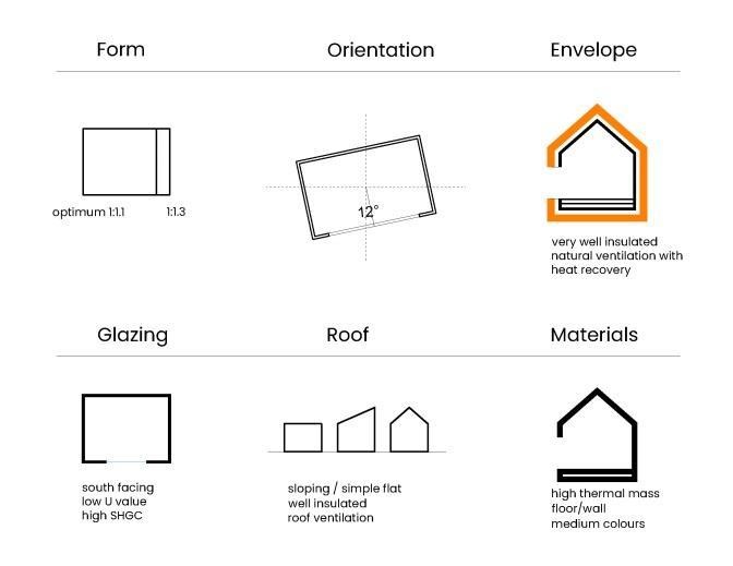
Building envelope - very well insulated building envelope components. The building's interior should have thermalmass. Also balanced ventilation with heat recovery is needed.
Windows - T The total glazed area should be limited in order to prevent heat losses. he south exposed windows should have largest surface. The east and west windows should be small. The windows should be shaded to prevent overheating and should have very low U-value and high SHGC (solar heat gain coefficient). Controlled cross ventilation is desirable.
Roof - A sloping roof encourages snow removal by wind action. Flat roofs should have simple form to prevent moisture penetration and ice-filled gutters.
Materials - High heat capacity mass in the interior will balance the extreme temperature variations. The west wall materials with 6 hour time lag balances the internal heat distribution.
Shadingdevices - Towards south, horizontalshading devices can be used.
Color - sun exposed surfaces can be in medium colors.
Figure3.33Coldclimatebuildingdesignguidelines
Temperateclimatedesignguidelines
This climate is characterized as temperate without dry season and warm summer. It is classified as Cfb according to the Köppen classification. Some European cities in this zone are: Berlin, Amsterdam, Brussels, Dublin, Paris, Warszaw, Prague etc. Recommendations for buildings` design in this climate are:
Sustainable Building Design 83
Building type - This climate permits the most flexible arrangement and free forms of the buildings.
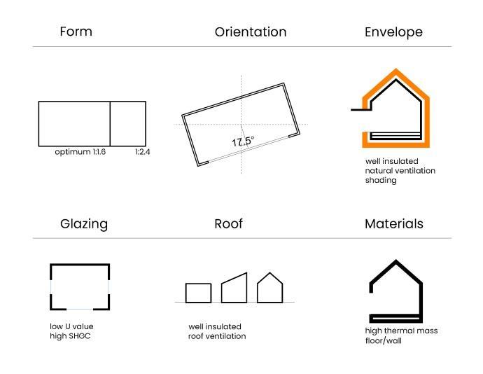
Form - Free forms are possible, however, elongation to the east-west is preferable with an optimum shape of1:1.6. The volume effect is not too important.
Orientation - The optimum orientation of the building is 17.5° east of south. The orientation of high buildings should be correlated with wind exposure.
Building envelope - Well-insulated building envelope is needed. Thermal mass coupled with balanced ventilation with heat recovery is beneficial. Operable shading systems are required to prevent summer over-heating;
Windows - The glazing should be energy efficient with very low to low U-value, moderate to high SHGC. South facing windows should be the largest with small openings on the west side. Windows should be positioned to provide cross ventilation and nocturnalventilation.
Roof - Eave and gable ventilation is needed which might be closed in winter.
Materials - Well insulated. The west wall materials can have 6 hour time lag balances the internalheat distribution.
Shading devices - Shading is needed from solar insolation in the overheated periods. Horizontal shading is recommended to the south, Eggcrate sunshade on the east and westsides while on the north side verticalfins are beneficial.
Color - Medium colors are advantageous, light colors on roof surfaces and dark colors possible on recessed surfaces.
Figure3.34Temperateclimatebuildingdesignguidelines
Sustainable Building Design 84
Hot-aridclimatebuildingdesignguidelines
This climate is characterized with summers which are hot and dry, due to the domination of the subtropical high pressure systems, except in the immediate coastal areas, where summers are milder due to the nearby presence of cold ocean currents that may bring fog but prevent rain (Mediterranean climate). It is classified as Csa according to the Köppen classification. Some European cities in this zone are: Madrid, Rome, Lisbon, Seville, Skopje, Athens etc. Recommendations for buildings` design in this climate are:
Building type - Proffered types are compact "patio" house type, row houses and other group arrangements with an east-west axis, which create a volume effect. High massive buildings are preferable.
Form and layout - Compact form is preferred with somewhat elongation to the east-west with an optimum shape of 1:1.3. In the layout, on the west side non-inhabited spaces should be placed to baffle the sun impact. Walled-in house arrangement can benefit from cool air pooleffects. The layout should be efficient and stimulate naturalventilation.
Orientation - The optimum orientation of the building is 25-35° east of south. For bilateralbuildings with cross ventilation 12° south ofwest is preferred.
Building envelope - Well-insulated building envelope is required with limited glazed area.The thermal mass and lower night-time temperatures provide comfortable indoor conditions after sunset (nocturnal ventilation). Natural ventilation should be provided for cooling during the day and night time.
Windows - Windows should have very low SHGC (solar heat gain coefficient). Also, they need to be protected from direct solar radiation and external shades are preferred. The openings should be located on the south and north, and to a lesser degree on the east side. Windows should be positioned to provide cross ventilation.
Roof - Well insulated and possibly ventilated roof. High solar reflectivity is required to prevent overheating
Materials - Well insulated facade. The thermal heat capacity of the walls can vary, such as: east - 0 hours while the south, eastand westwalls - 10hours.
Shading devices - Shading should be designed to prevent direct sunlight in summer. It is recommended that the devices should be separate from the structure and stimulate air convection.
Color - Reflective or cool colors exterior envelope surfaces (colors with low heat absorption to reduce the solar load during the summer period). White colors are recommended on sun exposed surfaces. Dark colors possible on recessed surfaces intended for winter solar radiation absorption
Sustainable Building Design 85
Hot-humidclimatebuildingdesignguidelines
This climate is characterized as temperate continental climate/humid continental climate without dry season and with warm summer. It is classified as Dfb according to the Köppen classification. Some European cities in this zone are: Bratislava, Milan, Budapest etc. Recommendations for buildings` design in this climate are:
Buildingtype - Individualand freely elongated buildings with loose density are preferred.
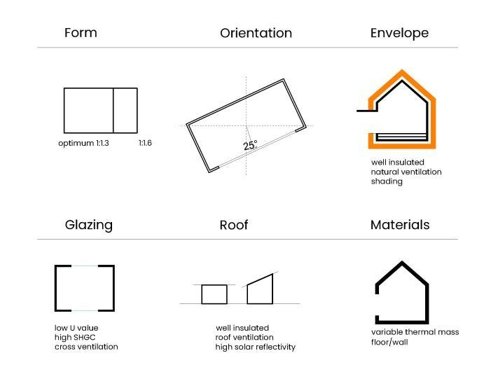
Form and layout - Elongation to the east-west with an optimum shape of 1:1.7 up to 1:3 is acceptable. The volume effect is undesirable. A free plan is possible as long as the building is shaded, with a free air movement inside the building. The plan might be organized into separate elements, since 75% of the time the outdoor conditions are near comfort if properly shaded.
Orientation - The optimum orientation of the building is 5° east of south. The orientation can differ due to wind directions, buy the building should be properly shaded.
Building envelope - It is recommended to design a heavy to moderately insulated building envelope Green roofs are recommended. The design should allow natural ventilation as essential to provide healthy and comfortable indoor air conditions without consuming energy for cooling
Sustainable Building Design 86
Figure3.35Hot-aridclimatebuildingdesignguidelines
Windows - Windows area should be minimized and have low SHGC. The glazing area should be protected from direct solar radiation and the shading structure should be sheltered from the sun and the rain. Cross ventilation is very important , as it is required 85% of the year.
Roof - Ventilation is required. Double roof can be applied with the upper roof serving as sun protection. Well insulated and reflecting solar rays. Wide overhang is required for rain protection and reduction of sky glare.
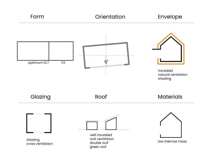
Materials - Walls with light heat capacity as thermal lag may cause night reradiation ofthe heat and morning condensation.
Shading devices - Solar control is needed mainly on the eastand westsides. It should be taken in consideration shading on the north wall as it can get more radiation in summer than the south wall.
Color - Reflective exterior envelope surfaces are recommended. Light and pastel colors are recommended in order to avoid glare towards the outside to the surrounding buildings as wellto the inside.
Figure3.36Hot-humidclimatebuildingdesignguidelines
Sustainable Building Design 87
4Passivedesign
D-r Aleksandar Petrovski, Lepa P. Hristovska, Atanas Petrovski
In today's architectural practice, the buildings` are becoming more energy efficient than ever before with the improvement of the buildings` envelope, by adding large amounts of thermal insulation and using mechanical devices to regulate the indoor temperature. However, large part of the new buildings are designed in a conventional manner and they don't fully utilize the potential of the local climatic context and miss the opportunities to create an even more efficient, comfortable and healthy building. Significant improvement of the forementioned aspects is possible by using Passive Building Design.
The Passive Design is based on exploiting the natural phenomena, such as the sun and the wind to reduce the buildings` energy demand for heating, cooling and lighting and create a healthy and comfortable building. By using passive design principles a building’s requirement for mechanical regulation of the indoor comfort can be even possibly eliminated. As a result, the passive building will contribute to the reduction of non-renewable energy use and reduction of the greenhouse gas emissions.
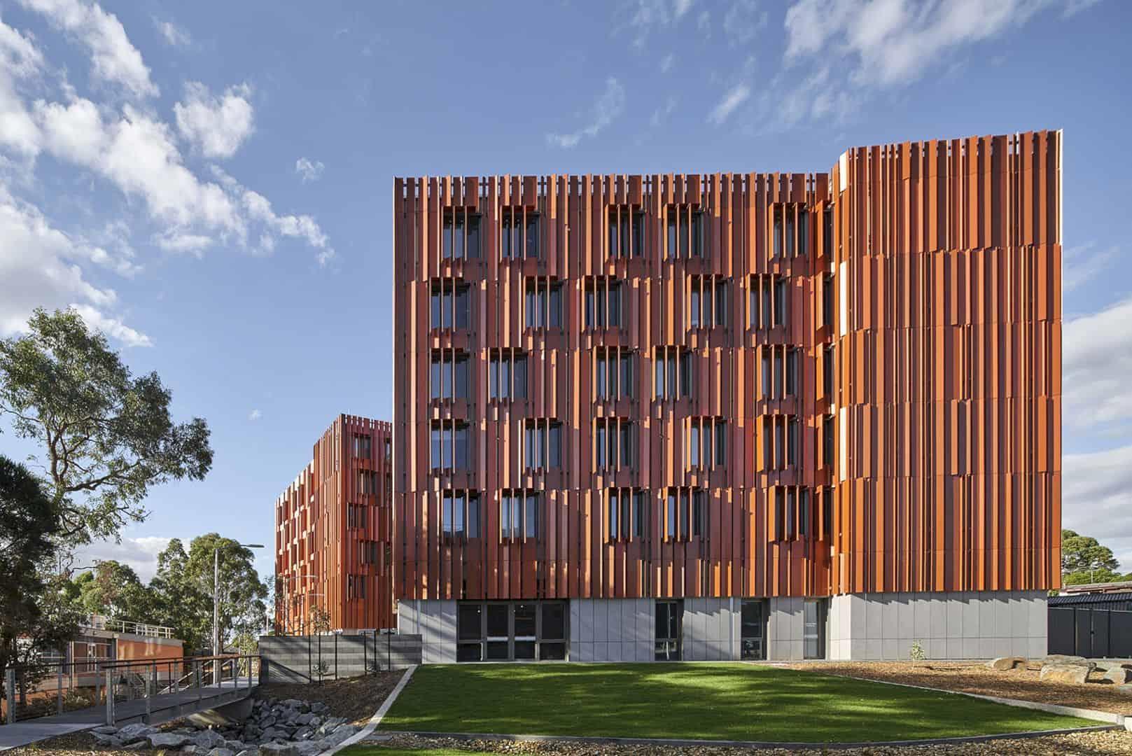
Sustainable Building Design 88
kWh/m2.a
Highly insufficient thermal insulation
Figure4.1Monashstudentdormitorypassivebuilding22
Ventilation electricity
Hot water Household electricity Space heating and cooling
Insufficient thermal insulation
Low-energy house Passive house
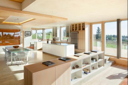
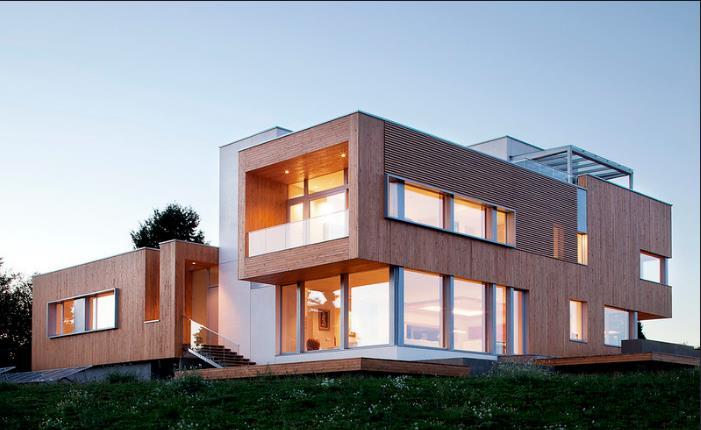
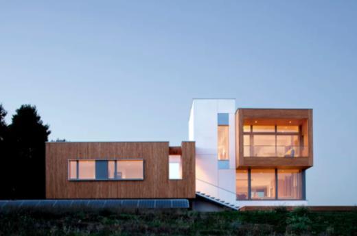
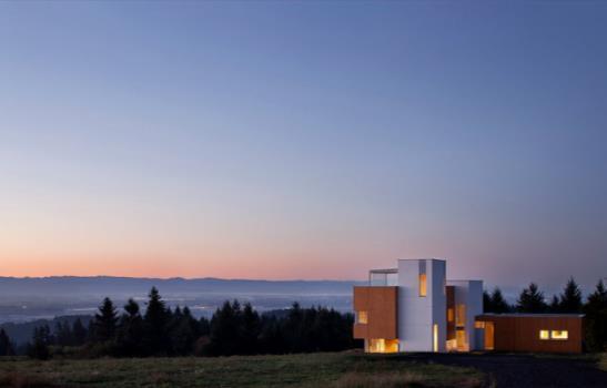
Figure4 2Comparisonofconventionalandpassivebuildingperformance
Many different factors will affect the Passive Building overall performance and these factors all interact: the site planning, the orientation of the building, the form of the building, the insulation, the airtightness, the mechanical system, the appliances and very importantly the activities of the people who live in the building.
Figure4.3PassivhausinOregon23
Sustainable Building Design 89
22 www.futuristarchitecture.com 23
https://archive.curbed.com/2016/9/6/12583346/passive-house-construction-guide 0 50 100 150 200 250 300 350 400
Which strategies and systems will be used in a building is dependent on the local climate. Climate related design aspects are discussed in the previous chapter and in this part we will get familiarized with the Passive systems and way they operate.
Passive building design needs to be based on a holistic approach. Implementing one independent passive design strategy can improve aspect, such as heating, or daylight. However, alteration made in one area of the house is likely to affect the conditions of the rest of the home. Therefore, the passive building is an integral system that can self-regulate by means of using the natural phenomena and the thermo-physical processes. In contrary, the active design approach utilizes mechanical equipment to collect and transport heat, while spending energy and electricity to run its operations.
The buildings designed according to the Passive Design principles have advantages such as:
Environmental performance: improved performance and reduction of nonrenewable energy consumption, greenhouse gas emissions, embodied carbon emissions etc.;
High Energy performance: very low energy consumption and lower bills throughout the year;
Interior Comfort: healthy indoor environment, high comfort levels (thermal, acoustic, daylight, visual air quality) and user satisfaction.
Higher Value: higher resale value, return on investment due to savings and considering future rise ofenergy prices;
LowerMaintenance:durable, reduced need for maintenance during operation.
Before we proceed deeper in these topics, we need to define the term we will mention often, which is the - buildingenvelope.
Buildingenvelope
The building envelope is the physical separator between the conditioned and unconditioned environment of a building which provides certain resistance to air, water, heat, light, and noise transfer. Simplified, it means that the building envelope is made of the walls, floors, roofs (or ceilings), windows and doors that separate the inside from the outside.
The building envelope is responsible for the main heat losses in the building. Depending on the thermal transmittance of the envelope in conventional building the losses are highest through the walls and roof, followed by glazed areas and ground.
Therefore, in sustainable and passive buildings, the envelope is designed as highperformance building envelope, meaning that it has better performance than the conventional constructions regarding controlling the heat and the other aspects. It must be continuous and free of thermalbridges as much as possible.
Sustainable Building Design 90
Figure4.4Heatlossesthroughthebuildings`envelope
The three basic elements of a building envelope are the thermal barrier, air barrier, and water barrier, which altogether provide high-energy performance and highly comfortable indoor environment.
Thermal control layer
In Sustainable and Passive buildings the amount of insulation applied is commonly larger compared to conventionalpractices, however, it should be carefully calculated.
In achieving thermally high-performing envelop, the term ‘super-insulation’ can be met, commonly designating use of thick layer of insulation. However, this doesn't have to be always the case. The amount of insulation is dependent on the Form Factor, described in previous the chapter, as well as to the external surface area of the building. The larger the external surface area, the greater the thickness of insulation will be required and vice versa, less surface area relative to the floor area, would require less insulation.
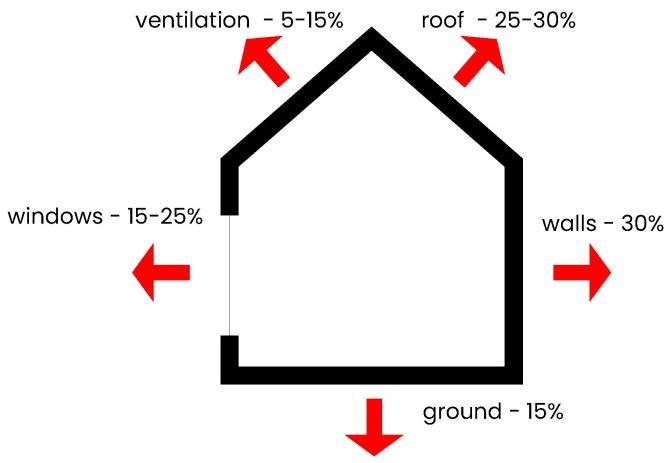
Air and vapour control layer
An airtight barrier on the inside of the insulation has several purposes. At first it stops air (and heat energy) that is inside the building from escaping through uncontrolled gaps in the building envelope. This ensures air only goes in and out of the building in a controlled manner, by naturalor mechanicalventilation.
The vapour control layer prevents moisture from inside the building getting into the building envelope where it might come into contact with a colder surface and condense. Where moisture does condense within the building envelope it increases the risk of mould and associated dangers, as wellas the risk of damage to the building envelope. This control layer also keeps the insulation dry and thus it preserves its performance.
A windtight barrier on the outside of the insulation is also required to preserve the performance ofthe insulation.
Sustainable Building Design 91
4.1. Passivhaus
The Passivhaus is mostcommonly defined as:
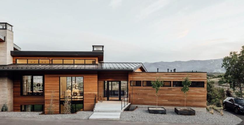
“a building, for which thermal comfort (ISO 7730) can be achieved solely by postheating or post-cooling of the fresh air mass, which is required to achieve sufficient indoor air quality conditions – without the need for additional recirculation of air.[50]”
Pre-requisite for meeting the criteria for Passivhaus building is the fulfillment of the design aspects thoroughly explained in the previous Chapter 3, which are related to: site planning, building orientation, building form, building layout and climate design principles.
A Passivhaus building should have south-facing orientation (in the Northern hemisphere) and even though, such building can also be achieved where a south facing orientation is not possible, the annualheating demand may increase by 30-40% because ofit.
Passive buildings design has the following characteristics:
1. Optimal Insulation - Passivhaus designs almost always feature higher levels ofinsulation above the current recommendations.
2. Airtight Building Envelope - The building envelope is extremely airtight, preventing infiltration of outside air and loss of conditioned air. All opaque components of the exterior building envelope must contain superior products and undergo various tests in order to determine the airtightness of the building.
3. High-performance windows and doors - double or triple-paned windows depending on climate and building type,
Sustainable Building Design 92
Figure4.5PassivebuildingbyKlimaarchitects24
24 http://klimaarchitecture.com/
4. Thermal bridge free design - Has a continuous insulation throughout its entire envelope without any thermalbridging. The joints, edges and penetration are carefully detailed to avoid thermal bridges. They can be difficult to eliminate completely, but their effects must be minimized to prevent detrimentaleffects for the building.
5. Heat recovery ventilation - Uses a minimal space conditioning system and has a balanced heat- and moisture-recovery ventilation
In order to qualify as a Passivhaus, the building should meet the following criteria: annual heating demand less than 15 kWh/m2 for heating and cooling energy, or with a peak heat load of10 W/m2 , annual primary energy consumption (energy for heating, hot water and electricity) should be less than 120kWh/m2 , the building must have an airtightness of 0.6 air changes per hour 50Pa.
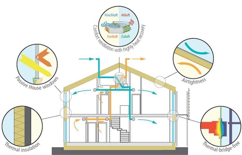
Figure
4.6FiveprinciplesofPassivhauss
25
As well as the original Passivhaus Classic, there are three related standards for new buildings plus another for retrofits, such as:
Passivhaus Plus generates the same amount of renewable energy each year that the building uses. That’s total energy use, not just energy for heating and cooling. The calculation also accounts for energy storage losses and the energy cost of transmission. It is the same classification as a net-zero energy building.
Passivhaus Premium goes further and generates as much renewable energy in a year that the building occupants use in their daily lives. It’s set at a level to make a fully renewable energy grid work for everyone. It is the same classification as a netpositive energy building.
Sustainable Building Design 93
25
about.html
http://www.passiveedge.com/passive-edge-homes
Figure4.7CharacteristicsofthePassivebuilding26
During cold periods (in the northern hemisphere) the building interior temperature is higher than outside due to heating of the space. The heat is lost through the envelope and the building cools down demanding more heat for maintaining desirable interior temperature. The inverse applies for summer periods (in the northern hemisphere) the excessive heat from the outside enters the building through its envelope. Therefore, it is required to restrict the heat flow in any building irrespective of the climate by applying insulation. By designing high performing building envelope the heat loss can be substantially decreased.
Thermal transmittance (U-values) of external walls, floor slabs and roof areas of Passivhauss range from 0.10 to 0.15 W/(m²K) (for Central European climate; these values may be slightly higher or lower depending on the climate). In countries in northern Europe, the buildings should have wall insulation up to around 33-35 cm (U=0.10 W/m2K), roof insulation thickness around 50cm (U=0.067W/m2K) in order to meet the criteria of the Passivhaus Standard.
The Passivhaus standard has been developed for the mid and northern European climates however its guidelines perform well in hot climates as well. High levels of airtightness and insulation work equally well in protecting buildings from overheating provided there is adequate solar shading in place.
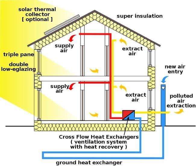
The Passivhaus Institute has listed the following recommendations for Southern European climates, such as::
Double glazing is acceptable in more temperate climates
Thermalmass and moisture absorbing (hydrothermal) materials gain in importance
Movable externalshading is essential
Maybe need for active cooling and/or dehumidifying
Any additionalcooling demand 15kWh/(m²a)
The ground can be used as a heat or cold buffer for tempering the supply air
Sustainable Building Design 94
26 https://www.bobvila.com/articles/passive-houses/
Passivhauss require different levels of insulation depending on the specific climate: more insulation in extreme climates with large temperature variation between winter and summer, and less insulation in milder climates where the temperature difference during the year is lower.
In buildings were the frequency of internal temperature above 25° C exceeds 10% of the year additional measures are required to protect against summer overheating. Cross ventilation and night cooling ventilation strategies need to be considered. Where such strategies are not possible Passivhaus permits 15 kWh/(m²a) of additional cooling energy to be used, which has proven to be sufficient in reducing unwanted heat gains.
Table4.1Passivhausrequirements
Passivhaus Low-energy house Conventional house, low insulation
Heating and cooling energy demand
Conventional house, no insulation
<15 kWh/m2.a 60-90 kWh/m2.a 150-200 kWh/m2.a 250-300 kWh/m2.a
Heating <10 55-80 140-185 20-30 Cooling <5 5-10 15-10 230-270 External Wall (d=25 cm) Insulation
U=0.15-0.25 W/m2K ~15-20 cm
U=0.5 W/m2K ~6 cm
U=1 W/m2K ~2 cm
U=2.45 W/m2K 0 cm
Roof Insulation U=0.15-0.25 W/m2K 15-25 cm
U=0.54 W/m2K 4 cm
U=0.28 W/m2K 10 cm U=1.38 W/m2K 0 cm Windows U=0.7-1 W/m2K Double/triple lowe glazing
U=1.2-1.8 W/m2K Double glazing U=2.7-5 W/m2K Single glazing U=2.7-5 W/m2K Single glazing
Ventilation/Air changes 0.6 ach/h Ventilation with heat recovery
4.5 kg/m2.a 12 kg/m2.a 30 kg/m2.a 75 kg/m2.a
Exhaust air unit Window ventilation Unsealed joints/leaks CO2 emissions from heating (from nonrenewables)
4.2. Passivedesignstrategies
The Passive Design is based on utilizing the building shape, orientation, layout and construction materials to regulate the performance of the building, to offset energy demand
Sustainable Building Design 95
and to provide healthy living environment for the occupants. All of the building design aspects which were discussed in Chapter 3 are a pre-requisite for achieving a passive building.
Further in the text we will have an overview of the three main passive design strategies such as:
Passive heating system Passive cooling system Passive ventilation system
They use the natural occurring phenomena such as such the radiation, conduction and natural convection, not requiring additional energy or mechanical devices. The beneficial solar radiation is stored in the space for warming the interior of the building during the colder periods when it is needed and to reduce the heating demand. Also, strategies are used to protect the building from overheating in the warmer periods. It utilizes the local winds to regulate the indoor air quality, to cool the interior and take out excessive humidity in the building.
Figure4.8EffectofPassiveDesignonenergyconsumption
We can also meet the term - Passive Solar Design which explicitly refers to the use of the sun’s energy for the heating and cooling of the buildings. It means that the solar radiation besides warming the interior it induces air movement which can be beneficial for the comfort.
Application of various strategies for passive heating, cooling and ventilation are shown below, which can also impact the daylight quality.
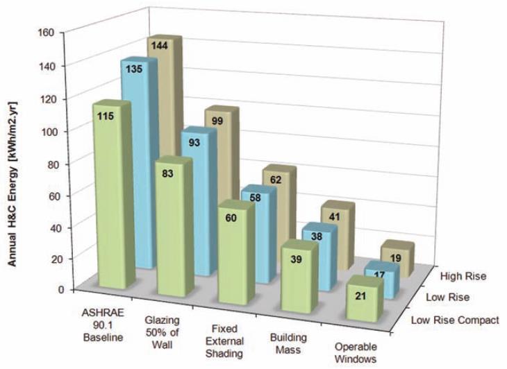
Sustainable Building Design 96
Figure4.9Strategiesinfluencingpassiveheatingandcooling27
Relative impact Passive heating Passive cooling Passive ventilation Daylighting
*** * * Highperformance windows
High performance envelope
** * * * Window to wall area ration <50%
*** * * * Bufferspaces *** * * * * External shading *** * * Thermal mass ** * * Compact form * * Air and moisture tight envelope
** *
4.3. Passiveheatingdesignsystems
Passive heating systems operate by collecting the solar energy which enters the building and store it in the materials with higher thermal mass, i.e. materials with a high heat storing capacity, such as concrete, masonry, water, phase-changing materials etc. The stored energy is then released back into the space when heating requirements are needed. In this way the energy demand for heating the building is reduced. Thermal mass will hold warmth longer in winter and keep houses cooler in summer. South facing windows are considered solar glazing. The area and orientation of the solar glazing and the thermal mass of the interior is interdependent. The more glass are is used larger size of the thermal mass must be provided in order to avoid overheating of the interior and discomfort. North windows lose significant heat energy and gain little useful sunlight in winter. The east and west windows are likely to increase air conditioning needs unless heat gains are reduced by carefulshading design.
Sustainable Building Design 97
27 Passive Tool Kit
Some studies recommend that the total direct gains glass area should be between 7-12% of the house floor area. Beyond that, issues with glare or fading of fabrics are more likely to occur. Also, it is more difficult to provide enough thermalmass and prevent overheating. The heating demand can be significantly reduced by:
Compact plan for reduction of losses through the building envelope.
Low U values of the envelope.
Optimize glazing ratios for heat gains, daylighting and artificiallighting.
Use ofshading systems adequate to the building orientation.
Use thermal mass to absorb solar insolation and reduce fluctuations in internal air temperatures
Proper detailing of building envelope junctions to limit air infiltration and prevent heat losses.
A balance must be achieved between the size, shape, and location of each of the five elements in the system to ensure optimal performance and efficiency. If the elements are not properly designed and they are too large then too much energy is collected and the building can be overheated. Or if they are too small then not enough energy is stored for the passive heating system to be effective. Also, another issue which can arise due to inadequate sizing is that the system either holds the energy in storage too long (oversized) or not long enough (undersized) to provide heat to the building when it is needed. The layout of the spaces is significant as wellin a beneficial heat energy distribution by passive means.
In case of undesirable winds, or from strong cold winds the building should be protected to reduce unwanted cold air infiltration. This can be achieved by landscaping, earth sheltering, vegetation, reducing the window openings on the undesirable side and providing airtight envelope.
Fiveelementsofpassivesystem
Every passive heating system includes five distinct elements:
Aperture (or collector),
Absorber,
Thermalmass,
Distribution and
Control.
They perform different function, but all five must work together for the system to be successful.
Aperture (Collector): The collector subsystem may include windows, skylights, or some other type of solar aperture which allow sunlight into the building to heat the space and, if appropriate, to heat the storage mass. The glazed area has to have optimal
Sustainable Building Design 98
orientation, such as south to south-east glass through which sunlight enters the building. Typically, the aperture(s) should face within 30 degrees of true south and should not be shaded by other buildings or trees from 9 a.m. to 3 p.m. each day during the heating season.
Absorber (surface): The surface which is directly exposed to solar radiation. It is often darkened surface of the storage element. This surface which could be that of a masonry wall, floor, or partition (phase change material), or that of a water container sits in the direct path of sunlight. Sunlight hits the surface and is absorbed as heat.
Thermal mass (storage): The purpose of the storage subsystem is to store the collected solar heat until it is needed by the occupants in the building. In winter the heat collected during the daytime is used at night. Stored energy is released from the storage mass and distributed throughout the building to offset heating energy use.
The type of material used, its thermal storage capacity, thermal conductance, thickness, and the room’s temperature dictate the quantity of energy stored and the length of time it stays in storage.
For example, a 10 cm concrete wall might store energy for 4 hours before completely releasing it as heat. Similarly, 60 cm of concrete might store energy for 18 to 20 hours before completely releasing it.
By varying the type of building material used, and its thickness, it is possible to substantially vary the performance characteristics of a passive heating system. The most commonly used materials in storage systems are concrete and masonry products.
The difference between the absorber and thermal mass, although they often form the same wall or floor, is that the absorber is an exposed surface whereas storage is the materialbelow or behind that surface.
Distribution: The method by which solar heat circulates from the collection and storage points to different areas of the house. A strictly passive design will use the three natural heat transfer modes–conduction, convection, and radiation–exclusively. In some applications, however, fans, ducts, and blowers may help with the distribution of heat through the house. Distribution can also be supported by arranging the functional spaces of the building such that those that need heat are closest to the storage subsystem.
Sustainable Building Design 99
Control: The control is achieved through the use of shading devices, or some other means to regulate the sunlight entering the building. Devices such as roof overhangs used to shade the aperture area and prevent overexposure to the solar radiation during summermonths and prevent overheating.
The size and shape of the solar apertures (collection subsystem) affects the quantity of heating energy available to offset auxiliary heating energy needs. The size of the storage subsystem affects the quantity of heat stored and the time delay between initial collection and final use of energy. The size, shape, and location of rooms in the building impact the optimum distribution of the heat throughout the building.
Heat distribution is accomplished by a combination of radiation and convection. Heat is radiated from the storage subsystem into the rooms being heated after the collected solar energy has passed through the storage system. Heat is convected through the air, warming it, and thereby warming the people in the room.
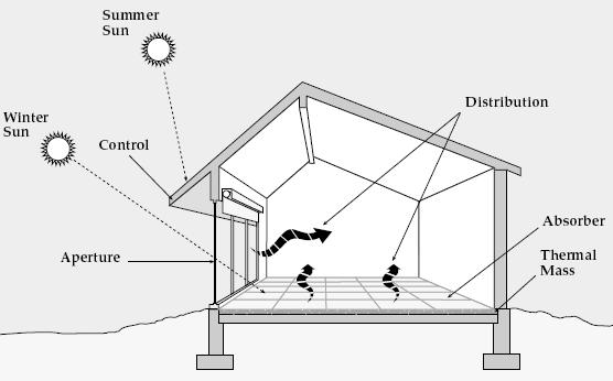
Figure4.10Elementsofthepassiveheatingsystem
Typesofpassiveheatingsystems
When a storage surface is illuminated by sunlight, the energy enters the mass and is stored as heat. The type of material used, its thermal storage capacity, thermal conductance, thickness, and the room’s temperature dictate the quantity of energy stored and the length oftime it stays in storage.
For example, a 4-inch concrete wall might store energy for 4 hours before completely releasing it as heat. Similarly, 24 inches of concrete might store energy for 18 to 20 hours before completely releasing it.
By varying the type of building material used, and its thickness, it is possible to substantially vary the performance characteristics of a passive heating system. The most commonly used materials in storage systems are concrete and masonry products.
In regard to how fast the storage system store and release the heat, they can be prompt or extended:
Sustainable Building Design 100
Passive heating systems that collect and distribute the heat in 4 hours or less are called promptsystems.
Ones that perform this process and take more than 12 hours to release the heat are called extended systems.
Most passive solar heating systems are designed to release their heat between 4 and 12 hours. This is often the case of passive heating systems in commercial or office type buildings, which are not occupied for more than 10to 12 hours a day.
Passive solar heating systems are categorized by the method of the transfer of the stored heat, i.e. the relationship between the solar system and the building, that is, whether or not the solar system is part of a room being heated, part of the building, or totally separate from the building.
Therefore, there are three types of passive solar heating systems, such as:
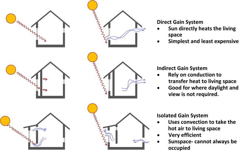
1. direct gain systems
2. indirect gain systems
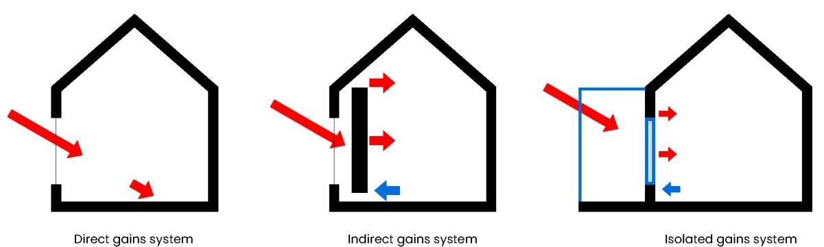
3. isolated gain systems
Figure4.11Typesofpassiveheatingsystems
Sustainable Building Design 101
4.4. Passivecoolingandventilation
Whereas the passive heating systems draw heat into the building, the purpose of a passive cooling strategy is to remove or reject heat from the building without using mechanical devices and without spending energy.
Solar and heat control techniques are used for the reduction of heat gains by using: landscaping, vegetation, high-performance glazing, thermal mass, shading, insulation, etc. Also, lower temperature sinks such as the ground, the ambient air and the water are used in order to remove the excess heat ofthe buildings.
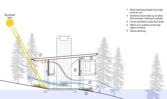
Generally, heat dissipation strategies are classified into three main categories:
Naturalventilation,
Evaporative cooling based on the use of water,
Ground cooling using the ground as a heat sink for building.
The shading and thermal mass are explained in other sections and the landscaping is out of the scope of this book. Therefore in this part we will focus mainly on the previously listed three strategies.
(DragonFlyHouse,OlsonKundig)28
Figure4.12Naturalventilation
Sustainable Building Design 102
28 olsonkundig.com
Passiveventilation

The cooling energy consumption can be up to 20% of the total energy demand of the building, and in warmer regions it can be more. Therefore it is beneficial to decrease the energy demand for cooling by using naturalventilation.
Another aspect must be considered is that conventional buildings mostly rely on mechanical air conditioning systems which contribute to larger energy consumption and frequently cause indoor air quality (IAQ) issues. Most newly built houses are airtight due to energy saving requirements. However, reduced air permeability leads to insufficient air exchange through infiltration, resulting in a negative impact on the health ofthe occupants.
According to the U.S. Environmental Protection Agency (USEPA) indoor air pollution is among the top five environmental health risks. Since people spend on an average of 80–90% of their time working and living indoors it is vital to maintain the indoor environment in a good quality. Poor air quality, can potentially cause “Sick Building Syndrome” and also metabolic diseases which are 30–200% more frequent in air-conditioned buildings.
On the other hand, in naturally ventilated buildings there are no issues of SBS and the occupant comfort and satisfaction is higher. Another important aspect is that, it it is estimated that naturally ventilated buildings cost about 10-15% less to construct than airconditioned buildings.
Therefore, naturalventilation has several purposes, such as: improving the indoor environmentalquality, providing fresh air for breathing and providing passive cooling and control of the indoor temperature and the relative humidity.
Ventilation in general means that there is an air exchange between the building and the outdoors. According to the ASHRAE Handbook ofFundamentals: “Air exchange of outdoor air with the air already in a building can be divided into two broad classifications: ventilation and infiltration.
Ventilationair may be induced as: - forced - naturalventilation, - infiltration, - suitably treated re-circulated air, or an - appropriate combination.
Natural ventilation is the flow of air through open windows, doors, grilles, and other planned building envelope penetrations.
Forced ventilation is the intentional movement of air into and out of a building using fans and intake and exhaustvents.
Sustainable Building Design 103
Infiltration is the flow of outdoor air into a building through cracks and other unintentionalopenings. Infiltration is also known as ‘air leakage’ into a building.”
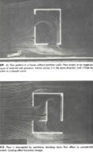
The ventilation and infiltration must be controlled in order to provide the required thermal comfort and indoor air quality to building occupants. A person needs 10 liters of air per second (0.01m3/s or 0.6 m3/minute) and if less air is provided then the building will have indoor air quality issues. The outbreak of the COVID-19 pandemic, stresses even more the need for adequate naturalventilation
The need for fresh air can be expressed by a unit called air exchange per hour, which represents the number of times all air within a building is being exchanged with outside air over the course of an hour. Further we will see how do we shape the building in order to actually get the air exchanges per minute as required.
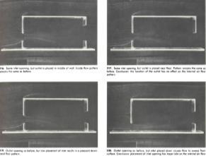
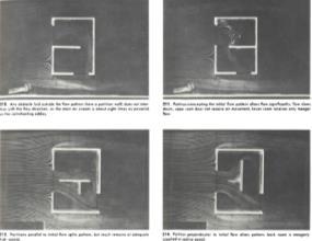
Depending on the climate, naturalventilation can contribute to 10–30% cooling energy savings. Studies in Chinese climate, show savings of 50-60% in cooling. According to other studies, the effect ofthe natural ventilation on decreasing the cooling load in appartments is shown in Figure below. The appartments have different orientation and those to the westand southwesthave the largestcooling demand, which can be decreased up to 80% by using naturalventilation.
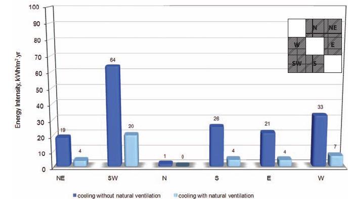
Figure4.13Effectofnaturalcooling
The airflow in the building is dependent on the wall layout, openings position, their size, furniture and similar. Straight flow provides the speediest movement, while any obstacles in the interior can cut air speeds markedly. The internal spaces can be zoned in order to maximize the potentialuse ofnaturalwind forces for natural ventilation.
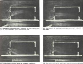
Sustainable Building Design 104
Figure4.14Airflowanalysis
It should be considered that in case of undesirable and strong winds, wind protection can be provided by wind-breaks and orientation of buildings, which is covered in other section. Research shows that in an unprotected building exposed to winds speed of 9m/s have up to 2.4larger heating demand compared to buildings exposed to wind speed of 2-2.5m/s.
Natural ventilation integrated with thermal mass is an effective passive cooling system that can be used to adjust the indoor environment to ensure indoor thermal comfort and maintain acceptable indoor air quality (IAQ). Natural ventilation can be applied for comfort ventilation during day (comfort ventilation) and for cooling the building at night (night ventilation).
Nighttime ventilation reduces the temperature of the internal mass of the building at night so that the mass will absorb heat during the day. The mass temperature is reduced by “flushing” the building with cool (low humidity) night air. The air reduces the temperature of the internalmass sufficiently to keep the building cool during much of the day. Naturalventilation can be utilized by: the orientation ofthe building (not necessarily perpendicular to the wind direction) use ofsurrounds to create low and high pressure zones
locating inlets in high, outlets in low pressure areas
smallinlet and large outlet sizes
inlets which direct the flow
undisturbed inside flow, open plan
The forces producing naturalventilation in buildings are:
air movement produced by pressure differences - wind and
air change caused by difference in temperature- stack effect (buoyancy). Therefore, the impact and effectiveness ofNaturalVentilation in the building depends on:
Prevailing wind velocity and direction
Building conditions and orientation
Window sizing, location, and functioning
Surrounding environment
Outdoor temperature and moisture
Sustainable Building Design 105
29
29 Olgyay
Infiltration
The infiltration in a building is measured with the n50 test, also named as, the blower-door test, which combines both under and over pressurization tests. The resultant air leakage at 50 Pascal's pressure mustbe no greater than 0.6 air changes per hour (0.6 ac/h @50Pa).
There is a difference between ACH50 and ACHnat and it is recommendable to reach an ACH50 <3. An ACH50<1.5 means that the building requires mechanical ventilation. Since the building in its regular occupancy is not decompressed at 50 Pa, in order to convert the ACH50 value obtained from the blower door test into the air exchange under natural settings, a rule of thumb is to divide the ACH50 by 20. Energy efficient houses have an average ACHnat of 0.5 h-1 (with a range of 0.02 h-1 to 1.63 h-1), compared to 0.9 h-1 for ‘normal new construction houses’.
The energy loads caused infiltration and ventilation are related with the the amount of air changes per hour: Qinfiltration= (ACH *volume *c x*ρ) * (Tinside-Toutside)
Where:
ρ = Density of Air 1.2 kg/m3
c= SpecificHeat Capacity of Air (20°C) ~1000J/kg K
The heat losses due to infiltration are similar to the heat losses by conduction through the wall, since the temperature difference between the inside and the outside is causing them.
Windandbuoyancyventilation
Naturalventilation can be caused by wind or buoyancy.
The wind is air movement induced by pressure difference and depends on the wind speed, the window size and placement. The buoyancy (stack effect) is caused by a temperature difference in a space and depends on the height difference between two openings (windows) in a same room.
The air flow or air movement is usually expressed through a volume flow rate, q. Typical units used are cubic meter/hour (m3/h) and liters per second (L/s). Sometimes, the ventilation rate is also expressed on a per person or per unit floor area basis.
q = area *velocity
Air flow is caused by a pressure difference. Air will flow from a zone of high pressure to a zone of low pressure. The bigger your window, the better for natural ventilation. But that has to be the upper part ofyour window.
The air flow speed is an aspect ofthe overallbuilding comfort as shown in the table.
Sustainable Building Design 106
Table4.2Comfortableairflowvelocity[53] Air Speed Impact of Building Occupants
< 0.25 m/s 0.25-0.5 m/s 0.5-1 m/s 1.0-1.5 m/s > 1.5 m/s
Wind induced air exchange
Unnoticed Pleasant Awareness of Air movement Drafty Annoyingly Drafty
As wind forces act on buildings, they typically create a positive pressure on the windward face and negative (suction) pressures on the walls. This type of ventilation depends on the wind speed, wind pressure on both sides ofthe building and position and size of openings.
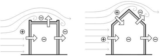
30
Figure4.15Windinducedpressureonbuildingenvelope
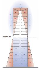
In order to determine where does the wind come from which can be used for natural ventilation we can use the wind rose map. The pressure coefficient for cross ventilation will be higher ifthe building is faced towards the direction where the dominant wind is coming from. The wind analysis can be made by using the wind wheel which is provided in many software tools, among which is the Climate Consultant or Weather tool in Ecotect. The Wind Wheel is a graphical visualization representing hourly wind speed, wind direction, relative humidity, and ambient dry bulb temperature within a specified time period.
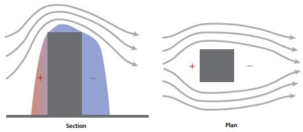
Sustainable Building Design 107
30
https://www.buildingscience.com/documents/digests/bsd-014-air-flow-control-in-buildings
Figure4.16WindwheelinClimateConsultant31
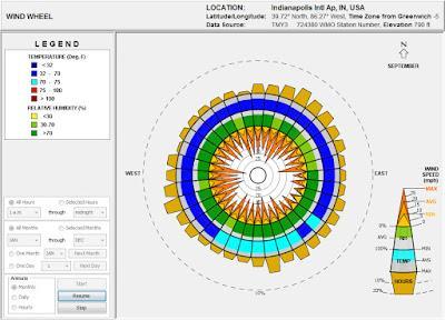
The outer rim of the wind wheel shows from which direction is the wind coming from and its prevalence. The blue circles represents the temperatures during the time period selected. The green circle shows for a given wind direction how high is the relative humidity. The wind which is very humid is not useful for the design as we don't want excess moisture in the building. Instead, the building, its layout or its openings should be oriented to utilize the beneficial wind orientation in the desired period, whether it is for ventilation or cooling.
Climate consultant enables choosing a specific time period for the analysis, which can be monthly, daily and hourly.
The wind in the standardized weather files is usually measured 10 m off the ground. However the wind speed changes relative to the physical barrier its size and height. The further above the obstacle the wind speed increases.

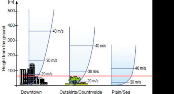
3233
Figure4.17Windvelocitygradient relativetophysicalbarriers
The wind that blows to the building creates positive pressure on the front of the building and negative wind pressure on the back of the building. Example of positive or negative wind pressure relative to the building orientation and form is shown in Figure below. The method showing in the graph is also used in the EnergyPlus tool.
31 https://www.buildingenclosureonline.com/ 32 https://www.flickr.com/photos/mitopencourseware/3030635318
33 https://docs.3di.live/b_wind.html
Sustainable Building Design 108
a.local pressure coefficient for wallsof low-rise building with varying wind direction
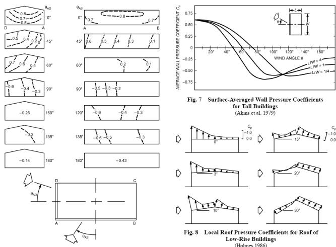
b. surface-averaged wall pressure coefficients for tall buildings (above)
c.local roof pressure coefficients for roof of low-rise buildings (below)
Figure4.18Windpressurecoefficients34
Another tool for wind analysis is the Weather Tool. It shows the wind rose of a given location, the direction, intensity and the amount ofhours the wind is presentfor a given year.
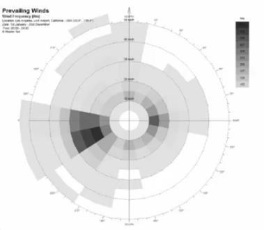
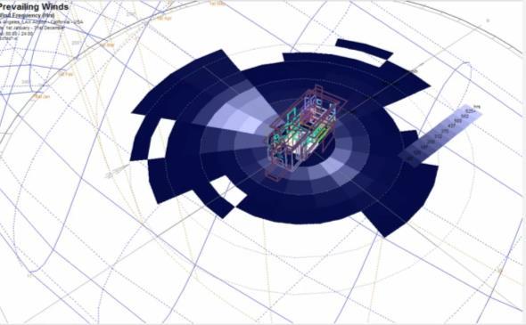
Figure4.19WindrosemapinWeathertool
By utilizing the wind or stack effect air movement, four types of ventilation can be distinguished, such as: single-side ventilation (i.e. operable windows), cross-flow ventilation (i.e. high- and low-levellouvers),
Sustainable Building Design 109
34 AHSRAE Fundamentals2005
stack ventilation (passive stack turrets) and top-down ventilation (i.e. wind-catcher systems).
a.single sided ventilation b. cross-ventilation c. stack ventilation
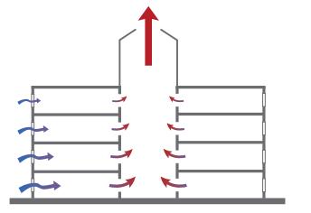
Figure4.20Ventilationstrategies[53]
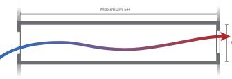
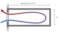
Sustainable Building Design 110
5 AspectsofSustainableurbandesign
D-r Jan Kazak
There are many theories and models that stand in line with sustainable urban planning. Such elements can be found in concepts of smart growth, compact city, urban village, ecopolis, low carbon urbanism, new pedestrianism/walkable city, livable city, etc. Summarizing elements that have been introduced in all these concepts few major components of sustainable urban design should be listed. These components are: density, forms and land uses, nature based solutions and social space.
5.1. Densityofacity
Density of a city influences its functionality, livability, attractiveness, economic feasibility, use of resources and many other factors that result in sustainable performance. Higher concentration of citizens and functions limits distances, reduces costs of infrastructure and transportation needs, saves more area for urban greenery, eases social interactions, reduces water and energy use. In order to preserve character of residential areas (and surroundings which guarantee ecosystem services to residential units) it is also important to keep clear borders of cities, for instance by green belts which were first used in England over a century ago.
Residential areas with higher density result in different access to many functions and services which increase the quality of life of their citizens. The example of accessibility standards for key services that should be located in residential areas are presented in Figure 1.1. (based on: [1])
Sustainable Building Design 111
Figure5.1Accessibilitystandardsforkeyservices
Sustainable residential urban areas should include for example local shops, nursery, primary school, community center, postoffice or pub in the closest neighborhood up to 1 km. In further zone up to 2 km secondary school, health center, leisure center or shopping mall should be located. Larger park, hospital or public institutions like museum or city hall in most cases can be located around 5 km from some residential units, however, lower frequency of visiting these places is not against sustainable patterns of everyday life in these areas. The most crucial aspect is to keep all the necessary services and workplaces, as well as places for entertainment and relaxation which are commonly visited more often in the area or closest neighborhood of residential buildings. The ideal is the distance that we can easily cover on foot in 5-10 minutes, which corresponds to 300-800 m (walking distance). They should be within such a radius from every place of residence locating basic retail outlets, clinics, nurseries, kindergartens, primary schools, meeting places for the local community, widely available sports facilities and small gardens and parks. A well-planned and designed residential area is an environment in which, moving in a relatively small area, we can live life to the full, realizing our everyday needs and ambitions [2]. Therefore, there is a need to calculate some basic indicators characterizing local communities in order to guarantee proper standards of public services. For example while building a new school it is possible to assume how many students can use it in a comfortable way. Knowing this number and the approximate number of kids per household we can analyze from how far student will have to come to reach a school. Lower density will result in the same number of kids on bigger area which will not support walking to school. As a result parents can be more eager to use private cars to transport their kids to school, which increase traffic on roads and emission of air pollutants. This example is applicable to many other objects and publicservices.
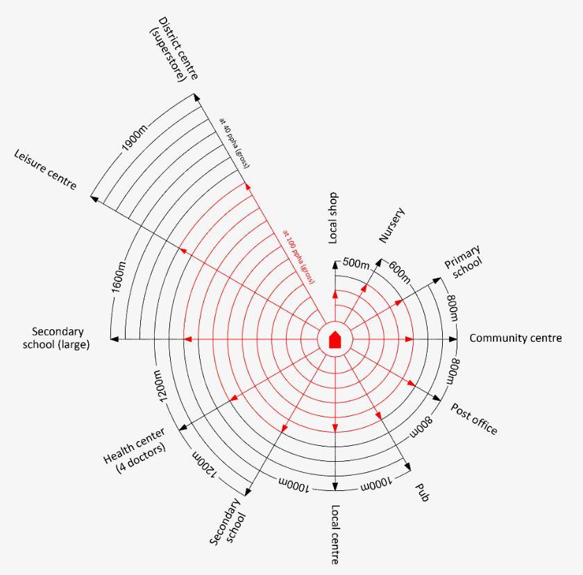
Sustainable Building Design 112
5.2. Urbanformsandlanduses
In addition to the population density and intensity of development, character of a city depends also on forms of objects. It is not a linear feature like “the bigger the better”. Tall buildings, for instance, are potential obstacles in access to the sunlight, in case they are located really close. Limited access to sunlight results in hugher demand of artificial lighting, increasing energy consumption and making this system more energy-dependent. In case of bigger distances between tall buildings, they become not the most dense form. On the other hand single family houses are even less efficient in terms ofdensity. One of the mosteffective form in that aspect are 4-6 storey buildings. That height of buildings does not force all users to use a lift, which makes this residential form more independent from external sources. Buildings with a perimeter form create the most multifunctional, diverse, socially diverse environment (thanks to the diversity of the size of apartments), and at the same time integrated. Continuous frontages favor the shape creating quiet, semi-private courtyards and well-defined interiors of streets, squares and gardens. Comparison of different urban forms characterized by the same congestion of citizens are presented in Figure 1.2. (based on: [3] after [2])
Figure5.2Comparisonofthreetypesofurbanforms
Depending on selected urban form of residential neighborhood we may influence the level of energy use if each district. Therefore, multi-family housing with 4-6 storeys buildings can easier reach high energy efficiency standards and follow requirements of Leadership in Energy and Environmental Design (LEED). Despite different functions of buildings, there is a specific category of LEED certification for residential35 . Considering more complex forms of
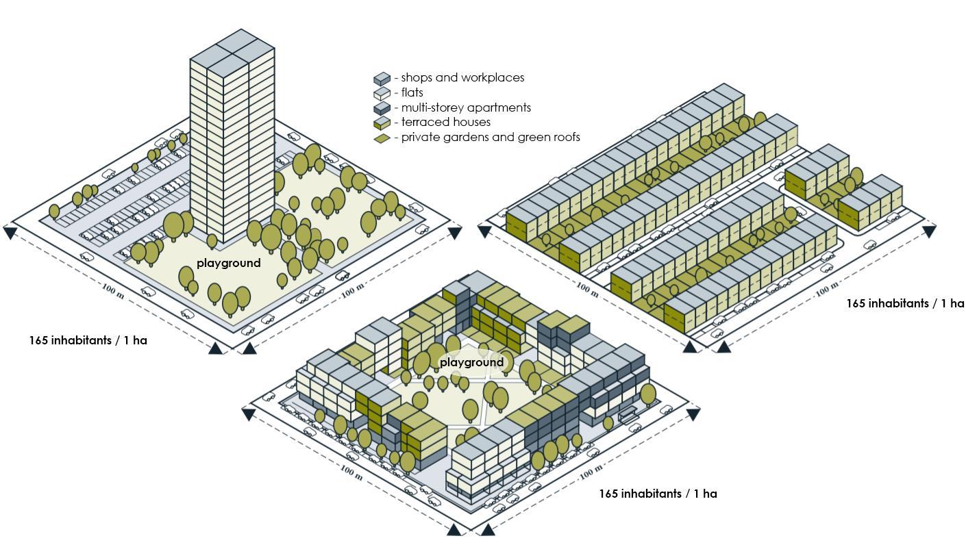
Sustainable Building Design 113
35
https://www.usgbc.org/leed/rating-systems/residential
residential buildings in form of whole neighborhoods LEED for Neighborhood Development was created to inspire and assist in the development of better, more sustainable, and wellconnected communities. It considers entire communities in addition to building scale. There are two levels of LEED for Neighborhood Development. The first one focus on plan phase. Neighborhood-scale project can be certified if it is currently in any stage of planning and design and is up to 75% complete. The second one focus on designed for neighborhoodscale projects that are nearing completion or have already been finished (within the last three years)36 All these solutions strongly rely on compact forms of urban structures with traditionalelements ofa city.
City squares have long served as focal points for local communities' social, cultural, and economic activities. They used to be primarily locations for the exchange of commodities, services, and information, but now they are primarily used for recreational purposes in residential areas as their local community centers. Each district's square should serve as a gathering area, surrounded by the most important public utility, cultural, service, and retail facilities, as well as residential buildings.
The principle should be the openness and permeability of all housing estates as well as the availability and multifunctionality of places used constantly for various purposes, by different users. The share of the housing function is of key importance. The constant presence of people increases safety and a sense of security. Monofunctional spaces, not integrated with the city structure, including industrial parks, shopping and administrative centers, and closed housing estates, are depopulated times of the day or night. Fences, cameras, police and fire patrols are not as effective in the face of a crime threat as the presence of residents who they can appear on the street or in the window at any time.
5.3. Naturebasedsolutions
Considering high level of quality of life that we should ensure to citizens and increasing environmental pressures by extreme events, one of the most important strategic goals of urban planning is to maintain right proportions between built-up and green areas in residential neighborhoods. Green areas, or wider, green infrastructure or blue-green infrastructure all fits to the umbrella concept of nature based solutions (NBS). NBSare defined as actions to address societal challenges through the protection, sustainable management and restoration of ecosystems, benefiting both biodiversity and human well-being. NBS have to be economically viable, resource-efficient, provide environmental and social benefits, adapted to local conditions, and as a result they should support adaptation to climate change. Based on the approach proposen in the project Nature4Cities there are three groups of NBS types that can be distinguished: objects, activities, and strategies. Similarily NBS can be delimited into technological units, spatial units, and supporting units or interventions [4].
Sustainable Building Design 114
36 https://www.usgbc.org/leed/rating-systems/neighborhood-development
Especially NBS objects and strategies are those two groups that should be considered in sustainable urban planning and designing
The first group of NBS are objects. Depending on a level of description it could be possible to refer to various details and names or definitions which differ in approaches used by some researchers. Some examples ofNBSobjects are:
• Green roofs (intensive or extensive),
• Green walls (climber green wall, planter green wall or green wall systems/living walls),
• Vegetated pergolas,
• Constructed wetlands for water treatment,
• De-sealed areas,
• Floodplains,
• Swales,
• Renaturation ofrivers and streams (meander geometry, vegetation on riverbanks),
• Urban meadows,
• Urban farming (including vegetable gardens, urban orchards or vineyards),
• Unsealed and planted parking lots,
• Green tram tracks,
• Street trees,
• Urban greenery (including pocket parks, large urban parks and forests).
Activities that can be considered as a separate group of NBS are: using fauna in urban systems (maintaining beehives, locating hotels for insects, use of grazing animals to maintain green areas), composting, interventions in greenery management to increase biodiversity. NBS activities do not appear usually at the city planning level, but as complementary actions support city management and the use of elements of urban ecosystem
The last group strictly connected with sustainable urban planning are NBS strategies. In this group we can distinguish protection and conservation strategies (zoning regulating specific land uses that are permitted, limiting or preventing access to selected areas to maintain natural processes) and urban planning strategies (connectivity of ecological network, equal distribution of public green spaces around the city, planning tools to control urban expansion on ruralor naturalareas (including green belts)). Examples ofNBS are presented in Figure 1.3.
Sustainable Building Design 115
Usually effective functioning of NBS requires holistic approach using all types of NBS to ensure that they create together green infrastructure that supports a city in a systematic way. Therefore, multilevel thinking is required in that aspect for planning a city that will adapt to climate change and its vulnerability to extreme weather events will be reduced.
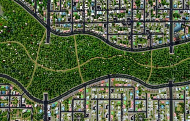
NBS play a significant role especially in case of residential areas due to the fact that in these parts ofcities people have the most frequent contact with them. Benefits from NBSmay cover different ecosystem services, including regulating services like air quality improvement, heat stress mitigation and pollination, supporting services like water cycle and photosynthesis, or cultural services like esthetical values and recreation area. All of them highly contribute to better standards ofresidentialareas.
5.4. Socialspace
NBS very often are located in public spaces which serve final crucial element of integrated city which is a social space. Well-designed, accessible and useful public places are the basic environment of social life and an indispensable component of sustainable urban structures. Their optimal functioning requires high-quality equipment and generating social activity, and this can be achieved thanks to appropriate design standards and efficient management. The basic standards include devices and equipment that guarantee availability of space for seniors, children, parents with small children and other groups of users. This holistic approach considering many social groups was a basis for the concept ofuniversal design.
Universal design (also known as Design for All) is an intervention into environments, products, and services that aims to ensure that anyone, including future generations, can participate in social, economic, cultural, and leisure activities with equal opportunities, regardless of age, gender, capacity, or cultural background. Because human beings are diverse, universal
37
Source: https://www.urbangreenbluegrids.com/measures/green-roofs/intensive-green-roofs/
38 Source: https://planningsustainable.weebly.com/green-belts-and-greenways.html
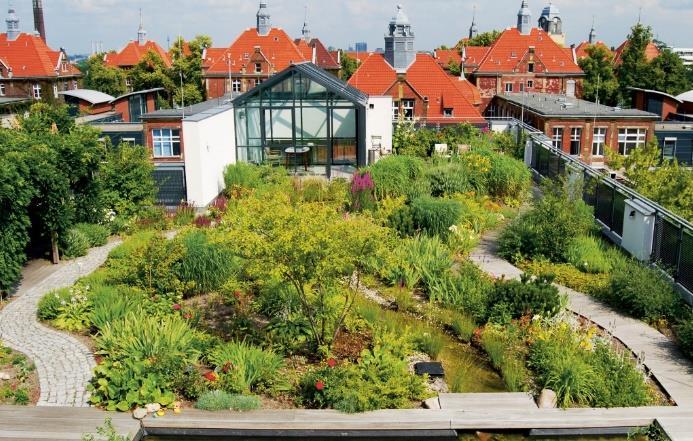
Sustainable Building Design 116
Figure5 3ExamplesofNBS:left–intensivegreenroof37,right–greenbelt38
design should be adopted in all sectors because everyone has the desire, need, and right to be autonomous and choose their own lifestyle without confronting physical or social constraints. According to the Design for All Foundation there are a few characteristics that should be considered when following universal design: respectful, safe, healthy, functional, comprehensible, sustainable, affordable and appealing.
Following these rules can help to make a public space really social and livable. That is the responsibility of local authorities to ensure such high quality of public space. In highly developed countries, safety, comfort and aesthetics of public spaces are sometimes considered as a criteria for assessing localgovernment and its effectiveness.
The interface between public and private space is of key importance for the development of local, small-scale entrepreneurship which complete residential neighborhoods (as described above in accessibility standards for key services). Especially the ground floors of buildings adjacent to streets and squares have a great activation potential, as long as safe and convenient access to the property is ensured. While upper floors are denominated for residential purposes, ground levels are suitable for basic everyday use functions. Calm traffic and wide pavements make it possible to introduce some services into the area of public space, e.g. in the form of very popular gastronomic gardens. Despite public space predesigned for social activity, also other public spaces (like transportation area) can be used temporary for different purposes for example during social events or in case of recent time to reduce social congestion due to COVID-19 pandemic. Having such solution within residentialneighborhood stimulate urban livability (Figure 1.4).
Source: https://www.dailysabah.com/life/health/is-it-safe-to-eat-at-restaurants-during-the-covid-19-pandemic

Sustainable Building Design 117
39
Figure5.4Examplesofsocialspaces:left–streetwithtemporarygastronomicgarden39
The return to traditional perimeter blocks (traditional urban forms often in a shape of regular squares or rectangles; popular until the beginning of 20th century) not only results in the creation of well-defined street and square interiors, but also enables the creation of semiprivate courtyards and yards, which, although open to outsiders, are mainly used by residents. The sense of belonging in such places is shaped by spatial form and, despite the lack of physical barriers to entry, the division between the private and public domains remains clear. The interiors of the perimeters are therefore an ideal environment for the maturation of neighborhood communities; an informally supervised place for play, rest and intergenerationalintegration.
Discussing social space, it is important to adapt well to the existing structures, architectural substance, infrastructure, greenery and forms of human activity. In many cases that refers to local cultural heritage, which brings identity to the community. The planning and design should reflect local cultural heritage and landscape memory and history. Historic buildings should be preserved under a classified protection system. Further, the plan should consider how to revitalize traditional cultures and to provide space for traditional craftsmanship, if possible. New buildings must comply with provisions on the preservation of regional history and mustbe in harmony with the site’s important culturalheritage if any [5].
Sustainable Building Design 118
6BuildingPhysicsandEnergyEfficiency
D-r Roman Rabenseifer
The main aim of this chapter is to make students aware of the relationship between building physics, mathematical calculations and computer-aided modelling of the future behaviour ofa building, including its energy efficiency. On this occasion, it should be said that not only in the future, but even now, the assessment of the future behaviour of a designed building cannot be done without computer-aided calculations, and the software used plays a significant role. In simplified terms, it could be said that software for computer-aided building performance simulation consists of three main levels.
The deepest, almost imperceptible to the average user, is the mathematical level, often called the computational module. At this level, the physical model is first transformed into a mathematical model and then the required calculations are carried out. The transformation is mostly automatic and is based on the chosen method that is specific to the software. Numerical methods, e.g. the finite difference method or the finite volume method, are the most commonly used. Above the calculation module there is a level defining the physical model, i.e. building geometry, material properties, boundary conditions, etc. This level may or may not also be organised in the form of several separate modules. The user cannot fail to notice it, since the creation of the physical model is actually the primary objective of the software. It requires the most work and time, but also knowledge of building physics. The actual data entry or data modification is done through the third level, the interface, as in the case of any other program. Through the interface, both the physical and mathematical modelcan be influenced.
In conclusion, the primary focus of this chapter is not computer simulations, but the creation of building-physical models for the purpose of the correct design of the building envelope or its individual components, not only in terms of energy efficiency, but also in terms of the quality of the indoor environment. Of course, in modern design, the creation of buildingphysicalmodels can no longer be done without computer-aided simulation tools.
We assume that the readers have a basic knowledge of building physics and thermodynamics. The aim of this chapter is mainly to review the knowledge and to complement it with the current state of knowledge in the field of building physics and thermodynamics and point out some key aspects.
Sustainable Building Design 119
6.1. Buildingphysicsandthermodynamics
The chapter deals with the following topics:
1. Thermodynamics - heat transfer - building physics
2. Basicmodes ofheat and mass transfer
3. One-, two-, and three-dimensionalsteady-state heat conduction

4. One-, two-, and three-dimensionaltransient heat conduction
Thermodynamics-heattransfer-buildingphysics
The concept of thermodynamics and its relation to heat transfer is well described by Incropera and DeWitt in Fundamentals of Heat and Mass Transfer [2]. The following text is a loosely translated quotation from the introduction of this publication: 'From the study of thermodynamics, we know that energy can be transferred by the interactions of a system with its environment. These interactions are called work and heat. Thermodynamics is concerned with the final state of the process during which the interaction occurs and provides no information regarding the nature of the interaction or the time value at which it takes place." The authors of the publication find it necessary to recall the basic differences between heat transfer and thermodynamics [2]: "Although thermodynamics is concerned with the interaction of heat and the fundamental role it plays in the first and second laws (of thermodynamics - author's note), it does not take into account either the mechanisms that provide for heat exchange or the methods that exist for calculating the values of heat exchange. Thermodynamics is concerned with equilibrium states of matter, where an equilibrium state necessarily precludes the existence of a temperature gradient. Although thermodynamics can be used to determine the amount of energy, in the form of heat, required for a system to move from one equilibrium state to another, it does not recognize that heat transfer is an inherently non-equilibrium process. In order for heat transfer to occur, there mustbe a temperature gradient, i.e. a thermodynamicnon-equilibrium.
The discipline of heat transfer therefore attempts to do what thermodynamics is inherently incapable of doing, namely to quantify the value at which heat transfer occurs in terms of the degree of thermal imbalance. This is done through the equations for the three modes of heat transfer - conduction, convection and radiation.“
Thus, in simplified terms, the thermodynamics is a pure science at the interface of physics and chemistry describing natural phenomena related to the energy aspect of systems and their changes, the heat transfer science is its extension to solve practical problems (Incropera and DeWitt call them "open end problems"), and the building physics is the engineering application of both the thermodynamics and the heat transfer science to the design of buildings. Of course, building physics deals not only with thermal and energy problems, but also with acoustics and daylighting and building insolation. Within this handbook, for the sake of simplicity, the term building physics is understood to mean that
Sustainable Building Design 120
part of building physics which is called building thermal engineering - sometimes the term thermal protection of buildings is also used. Either way, in the sense of this handbook, the main concern is with the issue of heat and energy transfer through building construction. It is the conceptual ambiguity that encourages constant awareness of the differences between the thermodynamics, the science of heat transfer and the building physics. The building physics, which is very practical in principle, is followed by an extensive system of national (e.g. STN, DIN, ASHRAE) and supranational standards (CEN, ISO) which tend to simplify the issue of heat transfer - in good faith. Their aim is to ensure the basic quality of products, in our case building products, building components and buildings as such. However, the assessment of products according to standards should, by their very nature, be simple and straightforward, with the result that heat transfer models are being simplified. This is fine in the normal cases for which the standards are developed. However, in special cases, heat transfer processes may be misinterpreted. In such cases, it is appropriate to go back one step, to the doctrine of heat transfer, to develop a more detailed model and to use this to demonstrate the suitability or non-suitability of the product, component or building design. A good example in this respect is the heat transfer coefficient, whose standardised values are now used almost as constants. In most cases, this is fine. In special cases such as, for example, building corners with sharp angles of internal surfaces and thus large radiating surfaces in close proximity, the use of standard values may result in an unrealistic heat transfer model. In such a case, it is better to define or model the radiative and convective components of the heat transfer coefficient separately, so that they describe the boundary layer as realistically as possible, based on the geometry and surface characteristics of the fragment under study. Such a model mustalready be based on the theory of heat transfer by convection and radiation, requires more detailed analysis and thus becomes, at least in terms of time, more demanding. Of course, the standard values of heat transfer coefficients are also based on the theory of heat transfer by convection and radiation, but the designer does not need to register it very much in normalcases.
A similar example is the issue of low-emissivity glazing layers or transparent thermal insulation, where a more detailed analysis is also required. In order to do this, it is often necessary to solve a large number of heat transfer equations. So-called computer-aided numerical calculation methods are used to solve them. Calculations of multidimensional and transient heat transfer are practically impossible without them. Fig. 5.1 maps the heat transfer calculations based on the heat transfer direction and the temperature state of the boundary conditions (steady/transient).
Sustainable Building Design 121
1D
Simplified model
2D
3D
Accuracylevelsofheatflow calculations Steady-state model Steady-state model
Transient model Transient model Steady-state model

Transient model Dynamicsimulationmodel
Figure6.1Overviewofheattransfercalculations
At this point we also naturally come to the question of suitable software. If one is proficient in mathematics, physics and programming, one can create and program one's own model using more or less any programming language or use software such as Matlab, designed for scientific calculations. Needless to say, however, this method is, even assuming a high level of knowledge, time-consuming and suitable mainly for non-routine calculations. The advantage of this approach is that almost anything can be modelled, with no predefined constraints. On the other hand, if one is mainly concerned with routine calculations and meeting the standard requirements imposed on the designed building fragments, specialised software focused on 1- and 2-dimensional transient heat conduction is quite sufficient.
Basicmodesofheatandmasstransfer
Heat propagates, as has been stated, in three basic ways - conduction, convection and radiation or a combination of these, provided that there is a temperature gradient in the transfer medium, the substance. Similarly (see [2]), the mass transfer occurs if there is a difference in the concentration of chemicals in the mixture. Just as a temperature gradient creates a prerequisite for heat propagation, a concentration gradient of the chemical substances in the mixture creates a prerequisite for the movement of these substances. However, it is very important to understand the context in which the term 'mass transfer' is used. It does not mean, for example, the flow of water in a pipe as a result of the mechanical work of a pump, although there is, of course, transfer of a mass. Rather, the term refers to cases such as the transfer, diffusion, of water vapour towards drier air, but it may also refer to other cases analogous to conduction and heat transfer. In building physics, the term 'mass transfer' is mainly understood as the diffusion and condensation of water vapour within the moisture content of building fabrics and structures. A special case in which the theory of heat
Sustainable Building Design 122
transfer meets the theory of mass transfer, and in which there is much analogy, is the field of air permeation and air exchange in building structures and buildings.
One-,two-andthree-dimensionalsteady-stateheatconduction
Heat transfer through conduction can now be modelled with relatively high accuracy by numerical calculations based on Fourier's laws of heat flux and steady heat conduction. The body under study (building construction) is translated by a raster, whose individual nodes correspond to the temperature distribution at a certain time instant. Such a raster is called a temperature field. For a temperature field, the temperature at each of its nodes is a function ofposition and time: = f(x,y,z,t)
We also call it a non-steady (transient) temperature field. If the function of time drops out of the above equation for the temperature at a node of the temperature field and the temperature depends only on position, the temperature field is called steady (stationary). Depending on whether we examine heat conduction in one, two or three dimensions, we speak of one-, two- and three-dimensional temperature fields. Two- and three-dimensional temperature fields are used when the heat flow through the structure is not ideally unidirectional. Such fields are also called deformed temperature fields or thermal bridges. The accuracy and speed of calculation of heat conduction in a deformed temperature field depends on the density of its grid. This should be freely definable, i.e. without limits from the side of the numerical calculation method used, although every software ultimately has some limits. In principle, materials with higher thermal conductivity can have a thinner raster and materials with lower thermal conductivity should in turn have a denser raster [4]. Some boundary conditions (e.g., convective heat transfer coefficients or temperature-dependent equivalent thermal conductivity coefficients), nonlinear radiative heat transfer, or transient heat conduction (by principle) require iterative calculations [4]. The results from individual iterative steps for individual nodes or even the entire temperature field should not differ by more than a predetermined deviation to ensure sufficient stability of the calculation. For example, EN ISO 10211:2008 specifies in its normative annex the requirements for the validation of numerical calculation methods. These should be met by any program for the calculation of2- or 3-dimensional heat conduction.
In several countries, 2- or 3-dimensional steady-state heat conduction calculations are mainly used for:

• Assessment ofthe resistance ofthe constrcution to heat transfer,
• Assessment of temperatures on internal surfaces of constructions containing thermal bridges in terms of the critical temperature for mould formation and the dew point temperature,
• Assessment of the impact of thermal bridges on the heat loss of the building or room under study.
Sustainable Building Design 123
The current legislation of several countries, e.g. Czechia and Slovakia, requires the above assessments in the project documentation for the building permit and also in the energy certification ofbuildings.
The issue of 1-, 2-, and 3-dimensional steady-state heat conduction is described in detail in the publication ‘Wärmebrücken’ [5].
One-,two-andthree-dimensionaltransientheatconduction
In contrast to steady-state heat conduction, the transient modelling is still highly optional. It mainly serves to improve the quality of projects in terms of validating proposed solutions, optimising them and, eventually, finding new, innovative and qualitatively better solutions. In certain circumstances, however, it can also serve as a tool for demonstrating compliance with the requirements of the relevant standards and thus also enter into (forensic) expert practice or expert activities. Not everything can be measured and, if so, these are often timeconsuming and costly processes. In such cases, computer-aided transient heat conduction calculations can be a suitable alternative.
The modelling of heat conduction in the non-steady (transient) state is based on Fourier's second law, which is described by Eq. (see [1]): ���� ���� =��(��2�� ����2 + ��2�� ����2 + ��2�� ����2)
where a is the thermaldiffusivity factor in m2/s.
The above relationship is also called the second Fourier differential equation of heat conduction. It is a partial differential equation from the coordinates of space and time as independent variables and temperature as the dependent variable. It gives the dependence between the temporal change in temperature (left side of the equation) and the local change in temperature (right side of the equation). The constant of proportionality in this case is the thermal diffusivity factor or thermal diffusivity (please not to be confused with thermal conductivity coefficient). According to this equation, the temperature changes most rapidly over time in those bodies that have a higher value of thermal conductivity. The thermal diffusivity factor expresses the change in temperature at a particular location in a substance relative to the change in temperature at the surface. The higher the thermal diffusivity factor, the faster the temperature inside the substance changes relative to the temperature change at the surface. To describe the temperature field for three-dimensional heat conduction, then: ����(��,��,��) ���� =��(��2��(��,��,��) ����2 + ��2��(��,��,��) ����2 + ��2��(��,��,��) ����2 )
For a steady-state temperature field, the left-hand side of the equation equals zero and has the following form: (��2��(��,��,��) ����2 + ��2��(��,��,��) ����2 + ��2��(��,��,��) ����2 )=0

Sustainable Building Design 124
6.2. Modellingheattransfer-classicalbuildingconstructions

It has already been mentioned in the introduction of this handbook that modelling heat transfer is not only a matter of knowing the physical laws and mathematical methods, but also a little bit of skill in building the model in terms of correctly selecting the factors really affecting the problem and omitting the irrelevant ones, as well as the appropriate use of software. The aim of this and next chapter is to highlight the possibilities that modelling the transfer of heat and mass in solving building physics problems provides and to allow trainees to try out modelling with pre-prepared examples. This chapter focuses on conventional building constructions, by which is meant conventional masonry or prefabricated structures with flat or pitched roofs. It gives three preliminary examples. However, it is envisaged that it will be expanded over time, based on feedback from module participants. The examples given are based on the use ofthe Physibelsoftware package.
This section deals with the following topics:
1. Constructions containing thermalbridges
2. Calculation of the heat transfer coefficient Uw ofa multilayer construction
3. Calculation of the heat transfer coefficient Uf ofa window frame
4. Calculation ofthe solar factor - g-value ofthe glazing
Structurescontainingthermalbridges
The modelling of constructions containing thermal bridges is described in detail in Wärmebrücken [1] and in Part A of the textbook Physics of the Indoor Environment of Buildings [1] (Chapter 5 Structures with a deformed temperature field). The description is based on EN ISO 10211:2019 Thermal bridges in building construction - Heat flows and surface temperatures - Detailed calculations. This standard specifies in detail the conditions for the correct calculation of heat conduction in a deformed temperature field in both steady and nonsteady state. One of the most common issues for which heat conduction calculations in a deformed temperature field are performed is the question of the risk of condensation of water vapour on the warm internal surface of the structure. If surface condensation does occur, it can lead to mould formation, which is unacceptable from both a hygienic and an aestheticpoint of view.
Sustainable Building Design 125
Figure6.2ExampleofathermalbridgegeneratedbyTRISCOsoftware[10]
CalculationoftheheattransfercoefficientUw ofamultilayer construction
The calculation of the U-value of a multilayer (opaque) structure is based on the calculation of its thermal resistance to heat transfer (R0), which is the sum of the thermal resistances of its individual layers (R), and also includes the thermal resistance to heat transfer at the inner (Rsi) and outer (Rse) surfaces. The calculation of the thermal resistance 'R' assumes that the layers (of different substances) are perfectly adjacent and perpendicular to the direction of heat flow. 'R' does not depend on how the layers of the different substances are arranged in sequence, since their resulting resistance is the same. However, in addition to thermal insulation, each structure must also meet other requirements (to store heat, to prevent condensation of water vapour, etc.), which depend on the order of the layers in the structure. The sequence of governing equations is as follows:
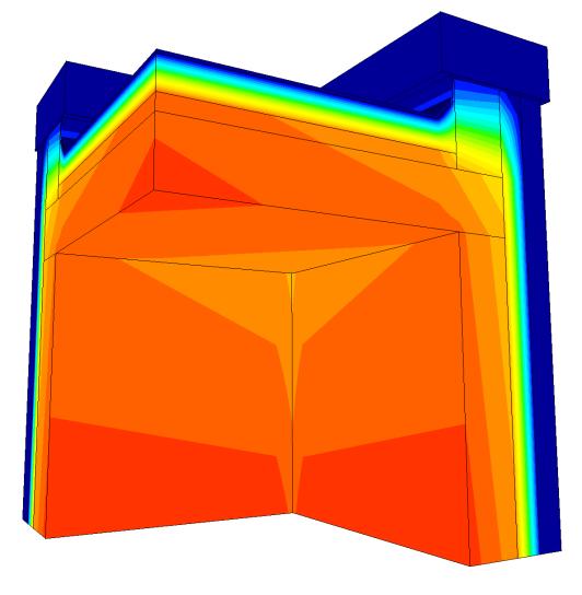
The unit of R, Rn ,R0 , Rsi and Rse is m2K/W and the one of U-value is W/(m2K). The thermal resistance to heat transfer at the inner (Rsi) and outer (Rse) surface consists of a convective and a radiative component.


CalculationoftheheattransfercoefficientUf ofawindowframe
The heat transfer coefficient can be calculated using two different methods:
Sustainable Building Design 126
�� =∑���� �� ��=1 =�� 1 +�� 2 +�� 3 + +���� ��0 = ������ +��+������ �� = 1 ��0
Method 1: The equivalent value of the thermal conductivity coefficient for all air cavities of the window frame determined according to EN ISO 10077-2: 2012 Thermal performance of windows, doors and shutters - Calculation of the heat transfer coefficient - Part 2: Numerical method for frames, Method 2: The radiative and convective heat transfer in the air cavities is taken into account using computer-aided numerical method, calculating the equivalent convective component of the heat transfer coefficient hc for the air cavities depending on the dimensions of the cavities and the temperature difference across them. The radiative heat transfer coefficient in the air cavities is calculated using the view factors model, where the emissivity of the adjacent materialsurfaces is set to = 0.9.
Calculationofsolarfactor,g-value,ofglazing

In contrast to opaque structures, characterised mainly by the thermal conductivity coefficient, the properties related to solar transmittance are also important for glazing. There are two main types of properties - solar and luminous. Solar refers to more or less the whole spectrum of solar radiation as an integrated radiation including both spectral and directional radiation, luminous refers only to its visible part - light and its direction of incidence and reflection. The "betrayal" is that the symbols for both solar and luminous characteristics, i.e. transmissivity (direct transmittance), , reflectance, , and absorptivity, , are the same. It is therefore a good idea to add the subscripts 'sol' (solar) and 'opt' (optical/luminous) respectively to avoid confusion. In addition to the above properties, the total solar energy transmittance factor, the so-called solar factor or also g-value, is given as a global characteristic of the solar properties. The solar factor, g, is defined according to EN 410:2011 as the sum of the direct solar transmittance, sol, and the secondary heat transfer factor, qi, through the glazing towards the inside. The secondary heat transfer factor is due to the longwave infrared radiation (emission) of that part of the incident solar radiation that has been absorbed by the glazing, and also due to the heat conduction and convection induced by it. The corresponding equation for the g-value is then i sol q g + =
The direct transmittance of solar radiation, sol, is a property of glazing. It is the fraction of incident solar radiation that passes through the glazing and can be described as the primary heat gain, g1, divided by the total incident solar heat flux (radiation intensity), e (some standards, such as ISO 15099:2003, use the symbol for the total incident solar radiation intensity instead of e). The secondary heat transfer coefficient, qi, depends on the absorption coefficients, , of the individual layers of the glazing, their emissivity, , and thermal conductance, , including cavities and the transfer of heat through surfaces. It is, as already mentioned, the absorbed fraction of incident solar radiation converted to heat flux by radiation, convection and inward conduction, which can be described as the secondary heat
Sustainable Building Design 127
gain, g2, divided by the total solar radiation intensity, e. A further expression of the g-value can therefore be: e
g g g 2 1 + =
The solar factor is one of the most important characteristics of glazing as it allows an immediate and reliable assessment of the future behaviour of the glazing in terms of solar heat gains. EN 410:2011 provides specific equations for calculating the g-value of single, double and triple glazing. The CAPSOL software uses the same physical principles as those underlying the development of the standard relationships. Based on these, it automatically calculates the g-value of transparent and semi-transparent fragments in its 'Wall Editor' (in the transmittance column, s, no normal material entry must be equal to zero). Figure 5.3 shows a "print screen" of a double-pane glass with a noble gas-filled gap and a lowemissivity layer on the inside of the outer pane. The calculated g-value is highlighted in red at the bottom right next to the U-value ofthe glazing.
The "print screen" of the Wall Editor spreadsheet with a double-glass composition with a gap filled with noble gas. The calculated g-value is highlighted in red at the bottom right next to the U-value ofthe glazing.
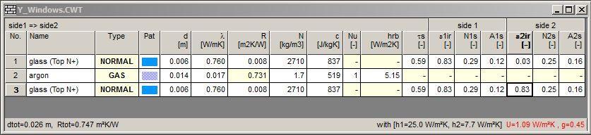
Figure6.3WallEditorEnergymodelling
In contrast to the modelling of heat transfer in building fragments, in energy flow modelling the power of energy sources enters into the balance to maintain the temperature of the indoor environment at the desired thermal comfort level. The energy source does not have to be only the heating or cooling (with a negative sign) system, but can also be the indoor equipment that provides heat to the indoor space as a result of its operation, e.g. computers, televisions, lighting fixtures or refrigerators. Another source may be the users of the indoor space themselves, e.g. family in the home or employees in the workplace. A special energy source is solar gains, which have been discussed in previous chapters and are, so to speak, part of the theory of heat transfer. The energy balance of an indoor space is expressed by the relation:
Sustainable Building Design 128
���� +���� =���� +���� +���� +��
where QT : heat loss due to heat conduction, QV : heat loss due to ventilation and infiltration, QS : heat gain from solar radiation,
QP : heat gain from persons,
QE: heat gain from indoor equipment,
H : output of the heating (+) / cooling (-) system
All quantities are in basic form in W, but can also be given as a function of time, e.g. in kWh, kWh.a-1or MW.a-1. If it is a specific heat loss or gain per unit temperature difference, W/K shall be given. The performance of the heating/cooling system should ideally correspond to the instantaneous difference in heat gains and losses. In reality, however, the instantaneous difference of heat gains and losses in a transient temperature condition depends on many changing factors to which heating/cooling systems cannot immediately react. So, when realistically sizing the performance of a heating system, the heat gains are not considered or, if they are, a sufficient margin is provided so that the system is able to cover even large temperature fluctuations. The importance of correct sizing of the heating/cooling system performance is documented in Figures 5.4 and 5.5, showing sufficiently sized and under-sized heating and cooling system. This aspect is often overlooked in the design assessment and certification of the energy efficiency of buildings, since in both cases the balance of heat losses and gains is made for a more or less constant temperature difference, the number of degree-days for a given location, and the resulting heating/cooling heat demand, even when the efficiency of the heating/cooling system is taken into account, may not be a guarantee that the thermal comfort of the indoor spaces will always be assured. It is therefore advantageous to be able to verify the behaviour of the building at the design performance of the heating/cooling system by computer simulation of energy flows using non-steady-state heat transfer theory. The aim is to be aware of the difference between steady-state and nonsteady-state calculation of the heating/cooling heat demand of a building and the possibilities that non-steady-state calculation offers in the energy optimization of a building. The ambition is also to arouse the interest of the trainees in computer simulations of future building behaviour and to motivate them to use them.
Although the creation of a computer simulation model is not a routine matter, it can often be used for routine calculations with a limited number of changing variables, e.g. for sizing an underground heat exchanger or optimizing the glazing and shading of a typical office in an office building. It can also be used in building management with a variety of promising opportunities, e.g. in estimating the projected heating and cooling costs of apartments or office units. Thus, people who have no or only minimal experience with building physics could very much profit from the work with simulation software. In order to overcome this problem, some IT-development companies create an alternative interface with a user-friendly environment, e.g. in Excel or as a web page, which allows changing some selected parameters, e.g. the required indoor air temperature, or even equipment models, e.g. for heating (radiant, hot air), without the end user entering the simulation software at all.
Sustainable Building Design 129
Sufficiently sized heating (grey) and cooling (blue) capacity; green curve = annual outdoor temperature, red curves = annual indoor temperature (graphical representation from CAPSOL)
Figure6.4Sufficientlysizedheating system
Under-sized performance of the heating (grey colour) system while cooling system is absent; green curve = annual outdoor temperature, red curves = annual indoor temperatures – especially obvious is their significant decrease during the cold periods of the winter months (graphical output from CAPSOL)
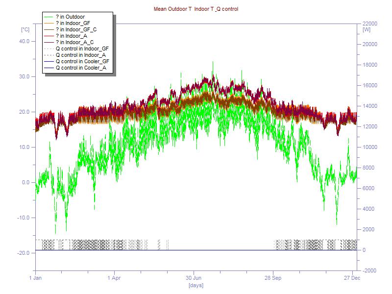
Figure6.5Under-sizedperformanceoftheheating(greycolour)system
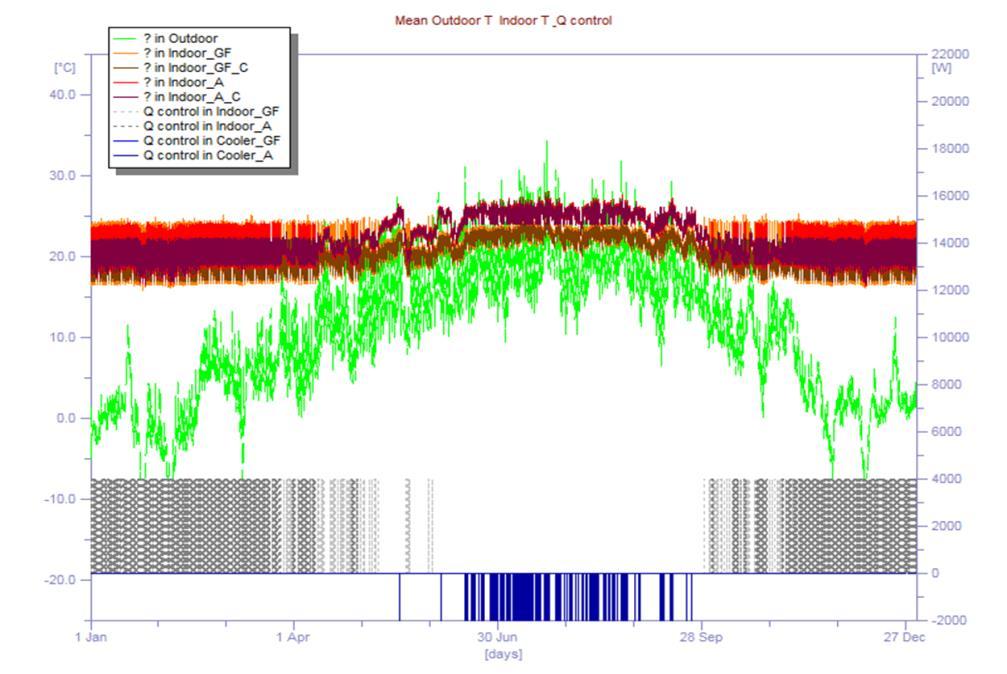
Sustainable Building Design 130
of
softwareandassociatedreplacementinterfaces Software External interface Informationonexternalinterface
Excel
DesignAdvisor
EnergyPlus DesignBuilder
Trnsed
Table6.1Examples
somewell-known
CAPSOL
www.cab.sk
Webpage(html) http://DesignAdvisor.mit.edu
www.designbuilder.co.uk TRNSYS
(html) www.trnsys.com,http://tessinc.com/home
Table 5.1 gives examples of some well-known software and their associated replacement interfaces. In English, this type of interface is sometimes referred to as PAT - Parametric Analysis Tool, and the simulation model itself as the "underlying/generic model". The surrogate interface is tailored, so to speak, to the specific simulation (generic) model and allows, as already mentioned, to change some of the parameters or to select the simulated devices. Figure 1.3.3 describes a flowchart of the operation of such a generic model created by CAPSOL software and "controlled" by a surrogate external interface, which is an Excel workbook. Figure 5.6 shows a typical section of an Excel workbook and Figure 1.3.5 the form of the output. Of course, the generic model created can also be used directly through CAPSOL. However, the Excel workbook simplifies the work if we only want to change some selected parameters. The actual "control" of the generic model from Excel is provided by macros created using VBA (Visual Basic for Applications). The principle of most macros for transferring data from Excel to CAPSOL and back, or for running a calculation in CAPSOL, is described in the publication Excel2007[7] by J. Walkenbach.
Interface(MSExcel)
Callpre-madeCapsol basedgenericmodel (ReadCapsolData)
Defineorselect calculationparameters
RunCapsol (-savesnewcapsolfile -runsthecalculation -readstheresults)
Genericmodelcreated usingCapsol
"Empty"genericmodel containingpresetheating systems,coolingand shading,whichmayor maynotbeusedina particularcalculation
Calculationusingthenew filethatcontainsa genericmodelwith defined/selected parameters,including selectedheating/cooling systemsandshading
Displayresults
Simplified diagram of the control of a generic simulation model created in CAPSOL software through an external interface, which is an Excel workbook.
Figure6.6Simplifieddiagramofthecontrolofagenericsimulationmodel
Similar approach has been chosen by developers of DesignBuilder [11] that “allows users to use EnergyPlus, change system parameters, run simulations, and process output without having to learn the intricacies of the entire EnergyPlus environment”. On the other hand advanced users are still given an opportunity to customise their simulations to match the realcase through a range ofmethods [11]:
- Modify the simulation input files, either manually or automatically in a script (requires the Scripting module).
- Customise the simulation using EMSruntime scripting (requires the Scripting module).
Sustainable Building Design 131
- Modify the EnergyPlus source code (for the more confident modeller with software development experience).
This way the alternative interface (generic model) can give the users high certainty that the achieved results are correct and can also contribute to the improvement of their knowledge, expertise in and feeling for simulation.
External interface created as an Excel workbook, through which the selected parameters of the created generic simulation model of a family house are entered or changed.
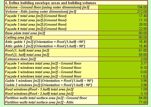
Figure6.7ExternalinterfacecreatedasanExcelworkbook
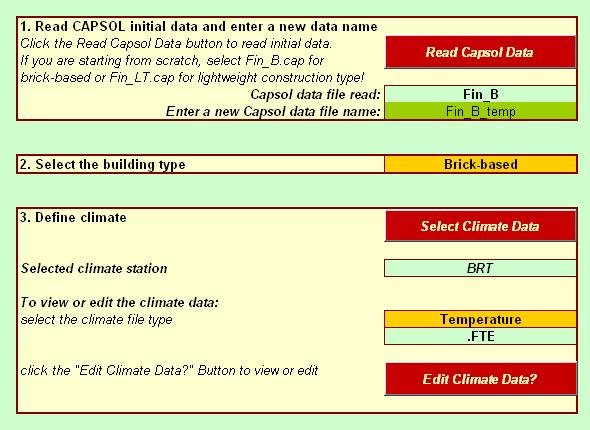
Sustainable Building Design 132
External interface to control the generated generic simulation model of the house - table with the loaded results and graphics for displaying the building energy performance and indoor comfort graph. The "RunCapsol" button starts the calculation in the CAPSOL simulation software.
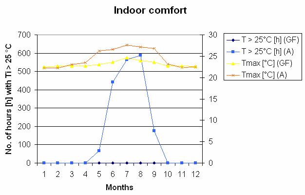
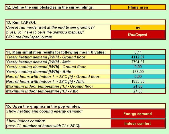
Figure6.8Externalinterfacetocontrolthegeneratedgenericsimulationmodelofthehouse
Glossary
The Glossary is loosely based on the publications Fundamentals of Heat and Mass Transfer [2] and Energy Conscious Design - A Primer for Architects [3] (concepts related to heat transfer and water vapour diffusion) and on Physics of the Indoor Environment of Buildings [1] (concepts related to air movement).
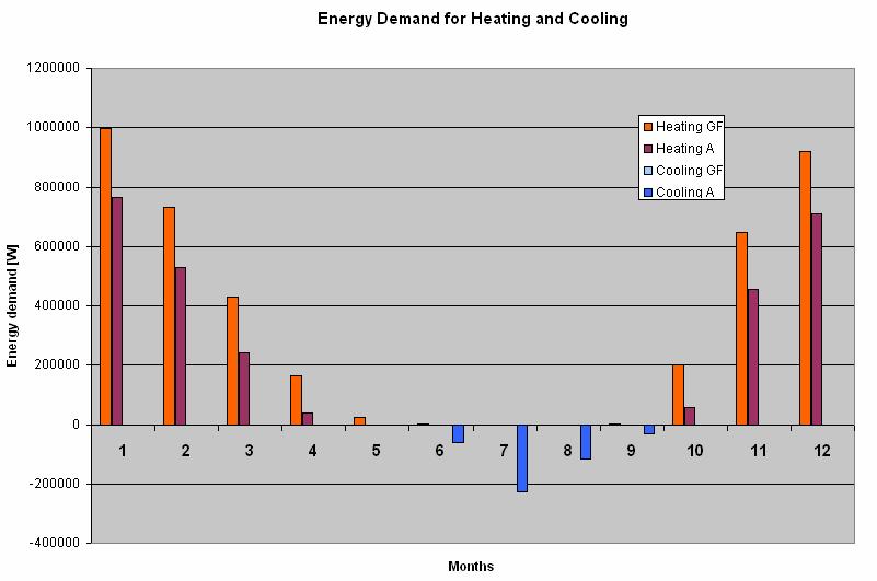
Sustainable Building Design 133
Thermodynamics - a discipline of physics describing natural phenomena related to the energy side of systems and their changes, i.e. laws of heat and thermal processes, relations between quantities characterizing the macroscopic state of a thermal system and changes of these quantities in physical processes associated with heat exchange between the system and its environment. It has three main laws - the law of conservation of energy, the law of impossibility of heat transfer from a colder to a warmer body and the law of behaviour of substances near absolute zero.
The science of heat transfer - based mainly on the first and second laws of thermodynamics, heat transfer (or heat propagation) is the exchange of thermal energy between physical systems. The rate of heat transfer depends on the temperature of the systems and the properties of the intervening media through which the heat is transferred. There are three basicmodes ofheat transfer: conduction, convection and radiation.
Building physics - a scientific discipline dealing with physical problems in the field of building construction. It has three main branches: building thermal engineering, acoustics and day lighting of buildings
Numerical computational methods - they serve to bridge the gap between the theory of mathematics and its practical application, since few problems described by mathematics can be solved completely accurately, even if the inputs are unambiguously specified. A numerical method is a precisely described procedure to solve a numerical problem. Every numerical method should include an error estimate. The basic characteristics of any numericalmethod are stability and convergence.
Heat - one of the forms of energy. It manifests itself as molecular motion in a body, liquid or gas or also as radiation in space. Heat is given in Joules, like other forms ofenergy.
Mass heat capacity (Cp) - the amount of energy required to raise the temperature of a given substance of unit mass by 1 Kelvin. It is given in J/(kg.K). The mass heat capacity of liquids varies with temperature and pressure. Older names for this quantity were specific heat capacity, specificheat, or justheat capacity.
Volumetric heat capacity - is the product of the mass heat capacity (Cp) and the volumetric mass (kg/m3) ofthe materialand is expressed in J/(m3K).
Sensible heat - can be perceived or measured. If the sensible heat of an object increases, its temperature also increases, and vice versa. This happens without any change in the state of the object, e.g. from a solid to a liquid state.
Latent heat - is the heat required to induce a change in the state of a substance, e.g. from solid to liquid. This change of state takes place at a constant temperature. The same amount ofheat mustalways be supplied or removed to reverse the change of state, e.g. water to ice / ice to water.
The laws of thermodynamics
Sustainable Building Design 134
• First law: the law of conservation of energy. Energy exists in different forms. It cannot be created or destroyed. It can only change from one form to another. In any system, the input energy is equalto the energy output plus the change in stored energy.
• Second law: the energy transfer is spontaneous and only in one direction. Always from a higher level to a lower level. In thermal energy, the transfer of heat takes place from a warmer body towards a colder one. It is not possible to reverse the direction of heat transfer without any externalinput ofenergy.
Thermal inertia - is an expression of the resistance of a body to a change in its temperature. It depends on its volumetric heat capacity and its thermalresistance.
Heat flux ( ) - is the transfer of heat in the direction from a higher temperature to a lower temperature. Heat flux therefore assumes both a heat source and a temperature gradient. Heat transfer occurs by conduction, convection and radiation. The rate of heat transfer through a body or space is the amount of energy passing through it per unit time, expressed in J/s or Watts. The heat flux density, q, is the rate of heat flux per unit area and is expressed in W/m2 .
Heat conduction - heat can be transferred through the object by conduction. It is a molecular movement by which heat spreads gradually through an object or between objects in direct contact. The extent of heat transfer through the object(s) depends on the size of the area considered perpendicular to the direction of heat transfer, the thickness of the object, the temperature difference between the two points considered and the thermal conductivity of the material.
Thermal conductivity coefficient () - is defined as the rate of heat flux through a unit area and unit thickness of a given substance at a unit temperature difference between its surfaces. The lower the value, the better the thermal insulating effect of the substance. The coefficient of thermal conductivity is given in W/(m.K) and expresses the ability of a substance to conduct heat. The resistance of a substance to conduction of heat (r) is the inverse of the coefficient of thermal conductivity, 1/ = r (m.K/W).
Thermal resistance (R) - is the product of the resistance of a substance and its thickness (m2K/W).
Heat transfer coefficient (U) - is the inverse of the thermal resistance, 1/R = U (W/(m2.K)). It represents the amount of heat transferred through a square metre of a material or multimaterialcomponent at a temperature difference of1 K between its inner and outer surface.
Convection- is the transfer of heat from the surface of a solid to a fluid (gas or liquid) or vice versa from a fluid to a solid. The rate of heat convection depends on the contact area, the temperature difference between the solid and the fluid, and the conductive heat transfer coefficient, the value of which depends on the geometry of the conduction, the viscosity and velocity of the fluid, and also on whether the fluid conduction is laminar or turbulent.
Sustainable Building Design 135
Radiation - heat can be transferred through space (in a vacuum or in a permeable or semipermeable medium) in the form of radiation from one body to another. The range of the wavelength spectrum of radiation depends on the nature and the surface temperature of the body. The amount of radiant heat flux depends on the temperature of the emitting and receiving surfaces, respectively on the emissivity and absorptivity of these surfaces. Solar energy reaches the Earth's surface in the visible band of the solar radiation spectrum, in the long-wave bands as infrared radiation and in the short-wave bands as ultraviolet radiation.
Emissivity () - is the ratio of the thermal radiation from a unit area ofthe surface ofa body to the radiation from a unit area of a perfect emitter, i.e. a blackbody, at the same temperature, or the ratio between the radiant flux density of the grey body, qs, and the radiant flux intensity ofthe blackbody, qb.
Dalton's law - the total pressure exerted by a mixture of gases is equal to the sum of the (partial) pressures that the individual gases would exert if they each occupied the same volume at the same temperature. This means that each of the gases in the mixture behaves as if the other gases were not present, and that the pressures coming from the individual gases in the mixture can simply be added together. It is assumed that there are no chemical reactions between the gases. Dalton's law applies to so-called ideal gases (source: Wikipedia). It also applies to a mixture of air and water vapour.
Water vapour diffusion - the movement of water vapour in a material based on its partial pressure difference.
Diffusion resistance factor () - indicates the number of times the material's resistance to water vapour diffusion is greater than the resistance ofthe air ( air = 1)
Equivalent diffusion thickness (sd ) - this is the thickness the air layer would need to have in order for its resistance to water vapour diffusion to equal the resistance of the material in question. It is given in metres.
Water vapour condensation - a thermodynamic process in which water changes from the gas to the liquid phase. It occurs at the dew point temperature, which is the temperature corresponding to 100% relative humidity at constant pressure
Air permeability - The movement of air in a structure by a pressure difference, from a higher pressure to a lower pressure, provided that the fabric of which the structure is made is porous, the pores are also interconnected, and/or the joints and cracks in the structure are leaky and air-permeable.
Air infiltration - characterises the air permeability through the structure. It is the volumetric flow ofair at defined conditions expressed as a function ofthe pressure difference
Air exchange - occurs during air infiltration and/or forced ventilation and is defined by the air change rate in 1/hr.
Selectivity (S-value) - The choice of suitable glass depends primarily on the requirements for indoor well-being in the planned room, and these can be quite contradictory. For example, in an office space we need to achieve the best possible daylighting, but we also want to avoid
Sustainable Building Design 136
overheating. The use of a low-emissivity coating reduces the light transmittance of the glass or glazing system, which is an unwanted side effect of reducing the solar factor. Therefore, in addition to the g- and U-values of the glass, the glass manufacturers also indicate the socalled selectivity of the glass or glazing systems to demonstrate their suitability in terms of these conflicting requirements. The selectivity or selectivity factor is the ratio of the optical transmittance, opt, to the g-value. The higher it is, the more suitable the glass or glazing system is in terms of the conflicting requirements for light comfort and reduction of summer overheating. The maximum selectivity value achievable with current technologies is around 2.
Sustainable Building Design 137
7 Daylightingdesign
Frantisek Vajkay
7.1. Introduction
Daylighting in architecture is a relatively new field compared to optics in physics, with which it’s intermingled, or to say without optics there wouldn’t be daylighting design. Daylighting uses the same advances, quantities and units which were and are still defined by physicists and mathematicians like Planck, Fresnel, Maxwell40, as well those unnamed ones from ancient and modern times likewise41,42. The only difference between these two fields is that daylighting is a building (architecture) oriented field. Therefore, it doesn’t care about the dualistic nature of light mitigation, or that energy is carried by photons moving from light sources towards objects in wave like motion. The division ofcosmicradiation and visible light spectrum can be seen ofFigure 6.1.
Figure7.1Cosmicradiationandvisiblelight 43
In optics the origin of light sources might be different, some natural, some artificial, some generating light based on incandescence, while other on bioluminescence, etc. Daylighting
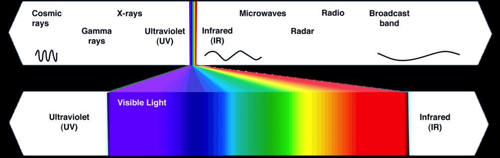
40 Boyce, P., a P. Raynham. 2009. SLL Lighting Handbook. London: CIBSE.
41 Sears, F. W., and M. W. Zemansky. 1965. University Physics, 2 ed. Boston, Massachusetts: Addison-Wesley Publishin Company, Inc.
42 Horňák, P. 1989. Svetelná technika. Bratislava: ALFA - Vydavateľstvo technickej a ekonomickejliteratúry.
43 (PNGWING nedatováno)
Sustainable Building Design 138
D-r
assumes that there is only one light source, namely the Sky. Albeit a sky couldn’t exist without the Sun and the cosmic radiation visible light is part of. There are differences in the Sky as well. Sometimes it is overcast, whereas at other times it’s cloudy or sunny. With the beginning of the 21st century a group of researchers from Bratislava (Slovakia) led by R. Kittler and S. Darula, defined a set of15sky types44 .
As it was already mentioned daylighting is a new field, which basically appeared World-wide at the time of Oil-embargo, causing the prices of energies to rise rapidly45. Even though world-wide is a bit over the edge, since the oil embargo influenced the western countries the most, and in some cases Building Codes of countries did contain certain requirements for sunlight availability already before the 1st world war, just Like the Austrian Hungarian monarchy. Since then, until 2018 (2019 in some countries) and even now, daylighting design is based on daylight factor, a derived quantity. Daylight factor is the ratio of two illuminance levels represented in percent’s. The numerator is the illuminance determined indoors or outdoors in a point which is shaded by different elements ����, while the denominator is the maximal value ofilluminance that can be obtained under the sky over a horizontal surface ����. Formulae 1. ���� = ���� ���� ×100[%] (1)
Daylight factor consists of three components: sky component, externally reflected component and internally reflected component. In case of sky component skylight reaches a reference point directly (or once it passes through the window). Externally reflected component requires light to reflect over the surfaces outside before if reaches a reference point. Internally reflected component is about coming to reflections of light over surfaces indoors. Figure 6.2. ���� =������ +������ +������ (2)
44 Commission Internationale de l’Eclairage, CIE DS 011.2/E:2002
45 Moore, Fuller. 1985. Concepts and Practice for Architectural Daylighting. New-York: Van Nostrand Reinhold.
Sustainable Building Design 139
Figure7.2ComponentsofDaylightFactor(byAuthor)
Daylight factor values can be determined by:
• On-SITU measurements of illumination. This approach is complicated because overcast sky is rare
• On model measurements of illumination under artificial sky. Artificial skies are rare World-Wide. The closest to us are in Vienna (At) and Bratislava (SK).
• By graphicaland numericalapproaches: o BRSProtractors, o Waldrams diagram, o Daniljuks angle grid for plan and for section, o And others.
• By computer tools: o Radiosity based: LightWave rendering software o Raytracing based: Radiance, Daysim, etc. o Others: Building Design WDLS, etc.
Long story short, the simplest (graphical/numerical) methods are faster for a small number of evaluation points, however they aren’t as precise as those modern tools. Nevertheless, a question arises. Is precision a must? - A tool which under rates daylight is often better because it’s on the safe side. So not really. Except if the calculations would/should include photorealisticrendering.
Daylighting design can be done in various stages of the building design process:
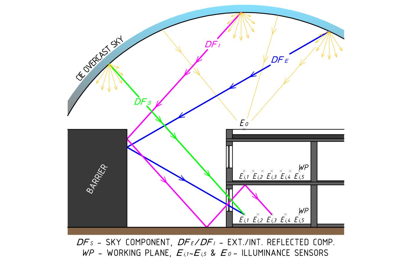
• Pre-design phase when it comes to evaluation of effects of the new build-up volume to its surroundings, to get a better overview ofhow big the new construction can be.
• In-design phase: evaluating the indoor environment ofthe designed building.
Sustainable Building Design 140
• Post-design phase: it’s complicated, most of the time it comes to this when neighbours aren’t satisfied.
So, in general it can be said that daylighting design is neither simple nor complicated. But can be both at the exact same time. Why?
• For 1 – it’s simple because:
o Light sources are already known, may they be naturalor artificial.
o Light reflectance and transmittance characteristics of matters used in the building industry and architecture have already been described and simplified. Current discoveries in these aspects won’t change much.
o Last not least the formulas for mitigation of light do already exist. And methods for simple hand calculations are verified.
• For 2 – Complicated:
o All of us have come across conditions and requirements given to heat losses and energy efficiency at least once. Thus, we already know that heat losses of a room are going to be higher when it’s daylit by bigger a window. The opposite is true as well. Nonetheless, with smaller windows it might be impossible to meet the required values for daylighting. Therefore, most of the time the daylighting design process results in a game, where one has to balance these two aspects.
o Another important aspect is aesthetics / an investors demands. It’s hard to meet the required values with respect to daylighting if a window is shaded by a deep and wide balcony, oriel, or loggia, while at the same time it’s also shaded by surrounding buildings. The only option available then is to raise the dimensions ofdaylighting systems. Or compromise here and there.
7.2. DaylightingdesignbyEN17037
Speaking about daylighting only, architects and engineers (or a specialist) are to know their local BUILDING CODE and European/local daylighting standards. Each country does have its own requirements with respect to distances between buildings, etc. As it was written with the year of 2018, when the EN 170737 Daylighting in Buildings46 standard was published, it became a bit simpler, because each country in Europe should have the same / similar conditions (still localstandards do apply as well, so for example effects ofthe newly designed building to the surrounding isn’t covered by the European standard). EN 17037 classifies the daylighting design process into four stages:
• Daylighting (itself): this stage is about quantification of incoming sky light, not sunshine, into a space.
46 CEN. 2018. EN 17037 Daylighting in Buildings. Comité Européen de Normalisation.
Sustainable Building Design 141
• Glare protection: This stage is about the minimization of dazzling, blinding effects indoors. Especially at working places and more, or less applicable to artificial lighting. For example, nobody wishes a chef to cut off his pinkie while chopping vegetables because he was blinded at a moment.
• View out: In this stage it is necessary to evaluate the quality of view from interior to exterior. It states what one can see when looking out the window. Is it the sky, surroundings and the terrain? A combination of these three brings the highest effects. A combination of two from the three is still acceptable. While only one visible aspect gets the lowest rating.
• Exposure to sunlight: Is about sunlight availability of indoor spaces. It’s determined for certain day of a year. It’s applicable to living spaces and such the most. Flats, houses, etc.
Glare protection and view out are new conditions for most of the countries in the EU.
Daylighting
Daylighting design as it was already mentioned is about quantification of incoming natural light to an indoor space, and its evaluation with respect to current local requirements. The requirements do differ from country to country, although the EN 17037 standard made it as clear as it can be. But it has its limitations. One of those is the dependence on EN 12464-1 standard. EN 17037 classifies an indoor space into ones with minimum, medium or high requirements. This classification results in slightly different requirements. To conclude that a space is sufficiently daylit two conditions are to be met at the same time:
• The target illuminance ET should be higher than 300 lx, 500 lx or 750 lx respectively over at leasthalfof the working plane. The values are included in EN 12464-1 standard.

• While the minimum target illuminance ET,m should be higher than 100 lx, 300 lx or 500 lx respectively over at least95% of the working planes area.
The target illuminance values can be converted to daylight factor values. Table 1 contains the converted values for Macedonia, Hungary, Slovakia, Poland and Czech Republic.
Table 1 Daylight factor values corresponding to 100lx, 300lx, 500lx and 750lx by countries46
Country 100lx 300 lx 500 lx 750 lx
Czech Republic 0.7% 3.0% 3.4% 5.1%
Hungary 0.6% 1.7% 2.8% 4.1%
Macedonia 0.6% 1.9% 3.2% 4.9%
Poland 0.7% 3.0% 3.4% 5.1%
Sustainable Building Design 142
Slovakia 0.6% 1.8% 3.1% 4.6%
Another evaluation method is based on Daylight Autonomy47, which is part of EN 17037. It handles about a year-long analysis of daylight hours. This requirement determines whether the target illuminance and minimum target illuminance values will be met for certain time periods a day.
Daylight factor and illuminance values are to be determined over a reference plane. The reference plane (mostly horizontal) as it can be seen on the figure below (Figure 1.3) is a grid of points, usually set up at a height of 850 mm above the floor (table level) and in a distance of 500 mm away from the closest walls. 850 mm above floor is standard for offices, classrooms, living spaces, and others. For kindergartens it’s at 450 mm (may depend on local conditions), gyms at 100 mm. The distance between points is around 500 mm, for bigger spaces the distance rises.
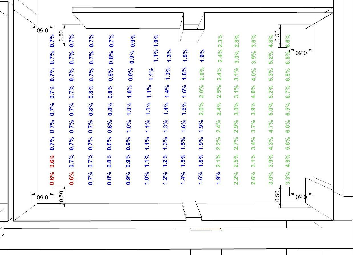
After the values are determined it comes to an evaluation. The space below meets the requirements at an area slightly larger than 70%.
47 New Buildings Institute, University of Washington, Integrated Design Lab, and University of Idaho, Integrated Design Lab. n.d. Advanced Buildings. Accessed 10 10, 2021. https://patternguide.advancedbuildings.net/using-this-guide/analysis-methods/daylightautonomy.
Sustainable Building Design 143
Figure7.3Referenceplaneset-upanddaylightingevaluationofaspace
Exposuretosunlight
Exposure to sunlight is related to three types of spaces: living spaces of flats (may they be in houses or blocks of flats), kindergartens, and rooms of patients in hospitals. Sometimes even to plots around residential objects and kindergartens. The methodology arose from British, Slovak, Czech, and German standards, which were modified to meet the needs of all European countries. Now everyone (owners, developers, architects) can determine for how long does sunshine into the windows / glazed elements of a room. This value is referred to as INSOLATION. It is a minute after minute analysis, where the procedure is kind of simple, it only verifies whether something stands in between the positions of Sun (formulae are in the standard48, they cover whole of Europe) and that ofevaluated point (see Fig. 1.4). When it comes to direct exposure it comes to an increment of insolation time. At the end the time is compared to a value in EN 1703746 or local standard. EN 1703746 classifies three stages for exposure. Table 2.
Table 2 Recommendations for daily sunlight exposure
Level of recommendation Insolation time
Minimum 90min Medium 180min High 240min
Local requirements might differ. For example, before the EN 1703746 was published in 2018 in Germany they required an insulation time of at least 120min for living rooms. The question is whether it’s the same even now.
According to EN 1703746 the evaluation should take place somewhere between 1st of February and 21st of March, with a minimal Sun altitude of 3°and 13°respectively. The resulting insolation time should thus be greater than 90minutes.

One can determine insulation time with the help of graphical or numerical analysis, or by 3D modelling and photorealistic rendering. There are various ways, simplest are the graphical approaches, since these clearly show what is to be changed. On Figure 1.4 the result of a simple graphicalanalysis is show, it was done in Rhino 3Dsoftware through python scripting.
48 Commission Internationale de l’Eclairage. 2002. „CIE DS 011.2/E:2002 Spatial distribution of daylight - CIE standard generalsky.“ Austria: Commission Internationale de l’Eclairage.
Sustainable Building Design 144
Figure7.4Determinationofexposuretimeofa spaceon21thofMarch.

As for the location of evaluation points. EN 1703746 clearly states where it should be. It’s at half of the opening’s width, 300 mm above the sill of the window but at least 1200 mm above the floor. Justas shown on Figure 6.5.
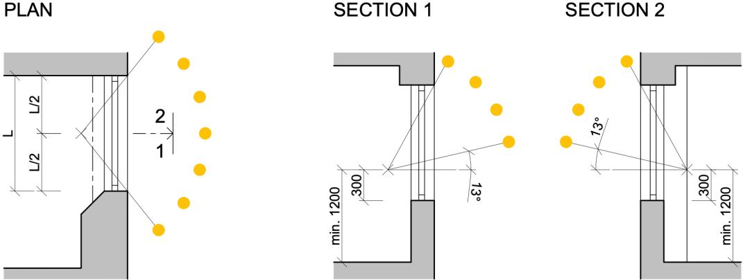
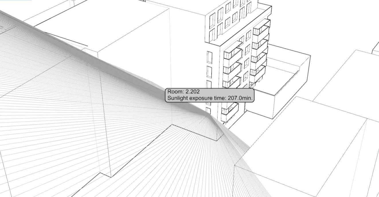
Glareprotection
Figure7.5Positionofevaluationpoint
In the EN 1703746 this requirement is following daylighting, whereas it is all about glare caused by direct daylight. Glare is caused by an increase of brightness in certain areas or by increased contrast ratio, which might affect the sight of the end-user by a blinding effect. Originally it was evaluated for artificial lighting design of workspaces49. Glare probability is
49 CEN. 2011. EN 12464-1: Light and lighting – Lighting of work places – Part 1: Indoor work places. Comité Européen de Normalisation.
Sustainable Building Design 145
analysed at eye level, that is at 1200 mm above floor level. DGP (daylight glare probability) can be categorized as visible in Table 3.

Table 3Recommendations for daily sunlight exposure
Criterion DGP
Glare is mostly not perceived ������ ≤0,35 Glare is perceived but mostly not disturbing 0,35<������ ≤0,4 Glare is perceived and often disturbing 0,4< ������ ≤0,45 Glare is perceived and mostly intolerable ������ ≥0,45
Shading elements or reorganization of a space are possible methods how to overcome problems related to glare. Reorganisation means moving work positions out of fields with high DGP.
Viewout
View out evaluates what and how much can be seen of the surroundings by looking out the window/daylighting systems at eye level (while in sitting position) around 1200mm above the floor. The assessment guide is related to the content of Table 4, which states the necessary conditions stated by EN 1703746
Table 4Assessment ofthe view outward from a given position
For spaces deeper than 4 m the sum of openings widths should be at least1 m and the height of openings at least 1.25m. Bigger windows on the other side don’t necessarily mean that more layers will be visible. There might be cases when the outside distance is beyond 50 m, but due a balcony and openings position and dimensions only the landscape will be visible. Or another case, when the neighbouring buildings are close, yet alllayers are visible.
Sustainable Building Design 146
≥
≥
≥
Parameter Level of recommendation Horizontal sight Outside distance of view Number of layers to be seen from at least 75% of utilized area: sky, landscape, terrain Minimum
14° ≥6�� At leastlandscape Medium
28° ≥20�� Landscape and another layer High
54° ≥50�� Alllayers are visible in the same opening
8Acoustics
D-r Frantisek Vajkay
8.1. Introduction
How humanity views sound, how it’s evaluated, etc. went through a tedious path of development. Sound plays an important role in life of humanity. It’s an integral part of the environment which gives people information about their surroundings and helps in communication.
Nowadays newer and newer sound sources are made, which produce a unique coulisse. As a result, the requirements for ensuring acoustic comfort in residential, civil, and industrial buildings are constantly growing. To ensure this acoustic comfort for the end-users, the issue of harmful sound, otherwise known as noise, must be addressed comprehensively at early stages ofbuilding design processes.
The first step of an acoustic friendly design is in the positioning of the building, i.e., urban design. A building with high requirements for noise levels (meaning low levels of acoustic pressure) in indoor spaces should be in a quiet environment. The concept of the building should be solved in a way that acoustically exposed spaces shouldn’t be adjacent to the acoustically protected spaces. It is a kind of prevention since acoustic protection of these areas from noise can be achieved by correct organization of spaces in buildings. This approach will also save expenses because the need to create acoustically insulating structures between spaces drops.
For a successful implementation of proposed acoustic countermeasures, a lot of attention must be paid to details. Additional adjustments are difficult to implement and unnecessarily increase the costs. It is necessary to focus on:
• Location of the building.
• Internallayout ofspaces.
• Design of partialbuilding structures.
• Look and sources ofnoise and vibration sources located in or near the building.
8.2. Perceptionofsoundbyhumans
The most important task of sound is the ability to provide a person with information about his surroundings. If a person stays in an acoustically exposed space longer, or more often, he or
Sustainable Building Design 147
she will start to consider the sounds that occur there to be normal. Typical for this behaviour is the sound of engine when driving. If a new sound appears, albeit of low intensity, the driver will register it and have unfavourable feelings from it. The degree of harmfulness of sound is determined primarily by its intensity and duration. Each environment has its own characteristicsound spectrum, typical for them.
The acoustic spectrum is a set of values of the monitored quantity, given as a function of frequency, Fig. 7.1.
Figure8.1Acousticspectrum
SOUND is composed of mechanical waves that are perceived by the hearing apparatus and which’s frequencies lies in the range of audibility of the human ear, i.e., in the interval from 16 Hz to 20000 Hz. Ultrasounds are mechanical waves with frequencies higher than 20000 Hz, and infrasound would then be waves with frequencies lower than 16 Hz. Human speech is between 500Hz and 5000Hz.
Annoying sound is referred to as NOISE. Nonetheless, what’s noise and not is subjective. One might take a rock concert as something beautiful, while another takes it as noise. Most of the times sound we refer to as noise does have a higher sound pressure level. See Fig. 7.2.
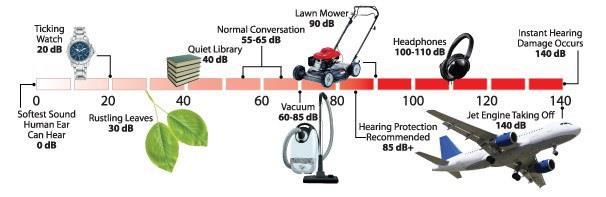
Figure8.2Soundpressurelevelsofcommonsourcesaroundus.50
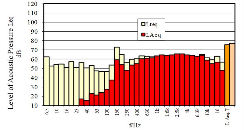
Sustainable Building Design 148
50
Thus, ACOUSTICS is a science that deals with the study of mechanical oscillations in a flexible environment and the study of phenomena associated with these oscillations. Its main purpose is to monitor propagation ofsound TOand IN building objects.
Sound might have its origin in:
• Exterior ofbuildings (traffic, bars and restaurants, and others). Option 1 on Fig 7.3.
• Interior ofthe building mitigating in the air (speech, TV, music, etc.). Option 2 on Fig 7.3.
• Interior of buildings but moving through structures (walking, falling objects hitting the floor). Option 3 on Fig 7.3.
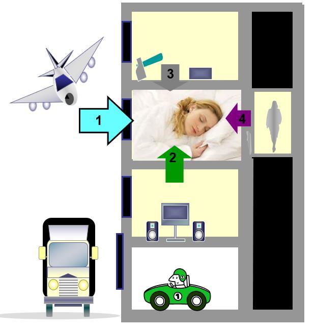
• From technological equipment (elevators, heating, plumbing, and such). Option 4 on Fig 7.3.
Figure8.3WaysofsoundpropagationTOandINresidentialbuildings(byP.Berková)
8.3. Buildingacoustics
The field of building acoustics deals with the propagation of sound in terms of sound insulation in relation with the protection of indoor environment of buildings from adverse noise.
The City of Albuquerque. 2021. City of Albuquerque. Přístup získán 2021. 10 10. https://www.cabq.gov/environmentalhealth/noise.
Sustainable Building Design 149
When sound spreads from one space to another through structures (inner - walls, floors, etc.; outer – peripheral walls, roof), it weakens. The attenuation is caused by the different characteristics of built-in materials like sound reflectance and sound absorbance (Fig. 7.4). In general, this is called as soundproofing. In building acoustics there are two types of soundproofing measures. One againstAirborne noise, the other againstImpact noise.
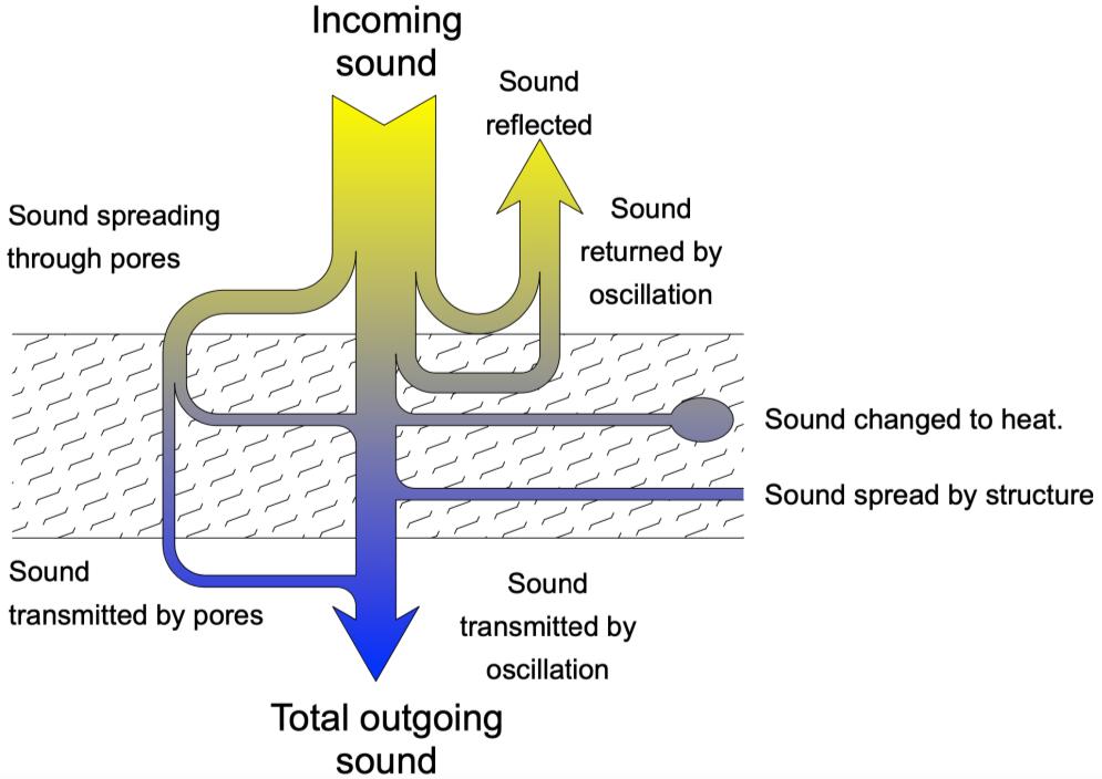
Figure8.4Attenuationofnoiseinstructures(byP.Berková)

Airbornenoise
Airborne noise insulation refers to the soundproofing characteristics of building structures against the propagation of acoustic energy with a source located in the air, through the structures, and propagating once again in the air of a neighbouring room. Simply speaking it’s about how much a wall attenuates the speech of a person going through it. Or another example: the persons are listening to music in adjoining rooms, one listens to rock music, the other to classic music. The sound passing through the structure is going to create and interference.
Airborne noise mainly affects neighbouring spaces. And there is a simple rule, the heavier structures between spaces attenuate airborne noise more, than light weight ones.
The values which are to be met are stated in local standards. Compared to daylighting, there is no generalization.
Sustainable Building Design 150
Impactnoise

Is the ability of the structure to dampen the so-called impact noise caused by direct contact of the sound source with the structure. Mechanical impulses cause bending waves in the structure, which propagate at different velocities from the place of origin in the form of vibrations, tremors. As a result, the structure emits impact sound in a protected space that belongs to the interval of vibrations (from 20 Hz upwards). The noise can be caused by walking in dress shoes over ceramic tile flooring, or by an elevator moving up and down. Vibration is then transmitted by anchors to the adjacent structures. The source of noise in the reception areas are then the surrounding vibrating structures, which radiate noise into the rooms.
The sound propagated by the structure can therefore be transmitted to more distant places. In older panel-based buildings, noise generated by washing machines are transmitted to the top floor from the ground floor, and vice versa.
How vibrations do propagate in structures is shown on Fig. 7.5.
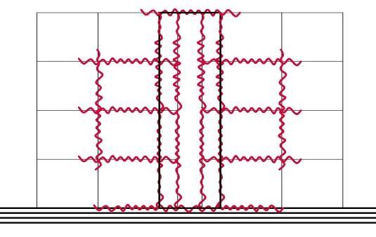
Figure8.5Propagationofvibrationsinstructures(by
 P.Berková)
Impact noise can be negated with elastomers, elastic bands, or absorbing mats under the flooring. The restaffects Airborne noise.
The values which are to be met are stated in local standards and they may vary from country to country. Compared to daylighting, there is no generalization.
Commonproblems
Today, building structures must simultaneously fulfil many requirements (thermal, acoustic, static requirements, etc.), which often contradict one another. The current trend is to make lighter building materials and structures, use precise blocks for masonries with lower bulk density, also dry binding processes. These indeed result in better thermo-technical and
Sustainable Building Design 151
structural properties, but adversely affect the acoustic characteristics which mostly depend on weight.
In building acoustics, airborne and impact noise resistances are evaluated in the range of 100Hz to 3150 Hz. However, new building processes and lightweight materials do result in problems at lower frequencies. The sound insulation capabilities of building structures are minimal at low frequencies. Signals at these frequencies pass through building structures with very little attenuation. They are so to say "filtered" by design so that high frequencies are attenuated, and low frequencies pass through.
Based on measurements performed in buildings it is possible to obtain values for airborne noise resistance, respectively for impact noise resistance. Fig. 7.6.
(a) and impact noise
Figure
(b) resistances (by P. Berková)
8.6Equipmentusedtodetermineairbornenoise
In Germany it is enough to design and construct a house with pre-set structures, in the Czech Republicand Slovakia measurements are to be made.
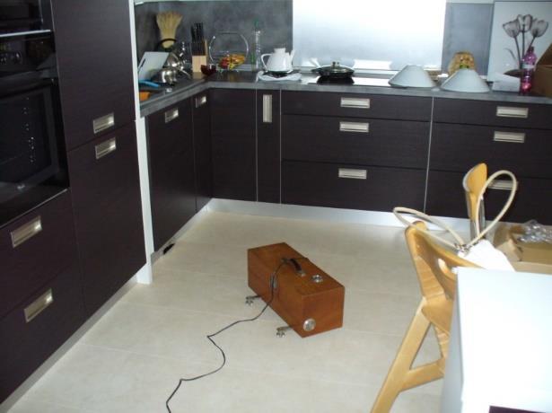
8.4. Spatialacoustics
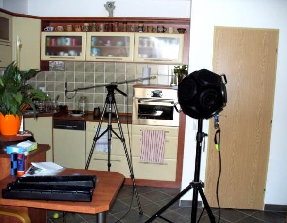
Spatial acoustics is one of the most demanding disciplines of building acoustics. It is no longer possible to rely solely on diffusion field theory. It is necessary to deal with other phenomena that affect the sound field in an enclosed space. Its aim is to ensure the best possible listening conditions for the sound generated by someone or something in a certain indoor or outdoor space. Spatial acoustics depends on reverberation time, decay time, intelligibility, and clarity. Another ofits aim is to diminish ECHO.
Every sound source generates two types of acoustic fields around it. Fields of direct waves (near the source) and fields of reflected sound waves (at a greater distance). The density of sound energy at any point of an enclosed space depends on the energy of the sound source and on the sound absorption of surrounding structures. It’s all about the law of conservation
Sustainable Building Design 152
of energy, where the sum of energy in a space and energy absorbed by structures equals to the energy emitted by the source.
The ability of a surface to absorb incoming sound energy is expressed by the sound absorption factor α [-], and its value is between 0 (total reflection) and 1 (total absorption). According to sound mechanics it’s possible to classify absorbers as:
• porous materials - these absorb sound at higher frequencies.
• oscillating panels and membranes - absorb sound mainly at medium frequencies.
• resonators - can absorb sound at low frequencies.
On the following figure an evaluation of an assembly hall is highlighted. The simulations were done in ODEON software by Yi Xu, Gang Liu51 .
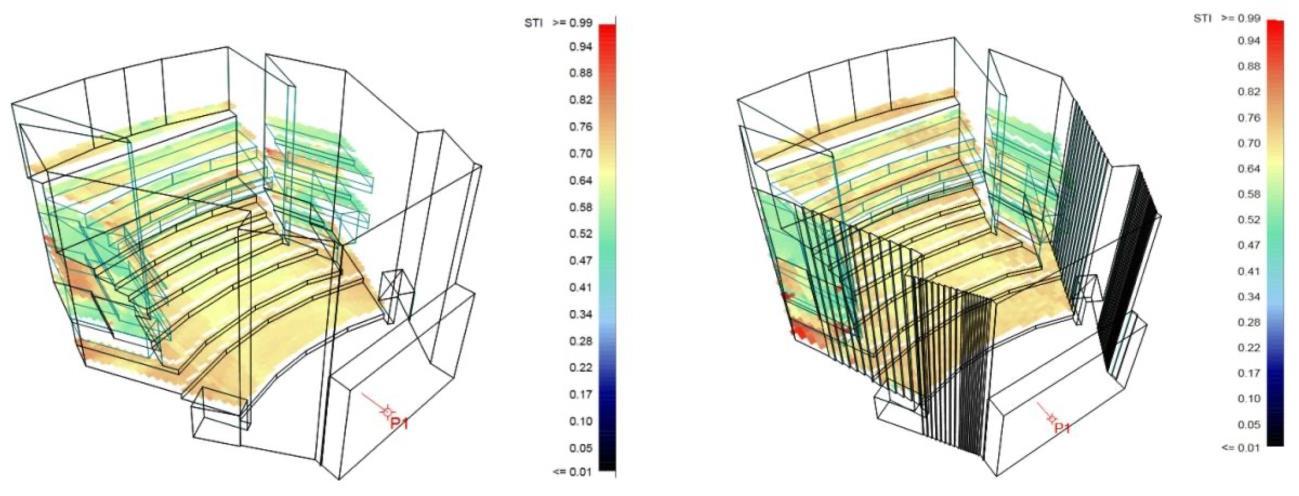
51
Figure
8.7DeterminationofEarlyDecayTime
The actual evaluation parameters are country and room dependant. There are different requirements for reverberation time for classrooms, cinema halls, and so on. Simplified calculations can be done as well, for example by Water’s methodology. But computer simulations allow a higher flexibility.
8.5. Noisestudies/Urbanacoustics
It’s last of the discussed topic, but usually first in case of a buildings design. Noise studies are used to evaluate the noise load of areas before the actual buildings are designed and constructed either with simplified methods or advanced computer tools. Computer tools are better, since with them it is possible to find out what the noise situation will be even after the construction works are done. Noise studies are required for almost all buildings, from family
51 Yi, Xu, a Liu Gang. 2014. „The Simulation of Acoustics by ODEON in the Acoustic Design of Assembly Hall.“ ASIM 2014 IBPSA Asia Conference. Nagoya, Japan: IBPSA. 555-563.
Sustainable Building Design 153
houses to residential buildings, through production and sporting facilities, cultural centres, roads, railways, wind turbines, airports and more. It’s necessary to evaluate the effects coming from different noise sources at day and night times (separately). For example, the effects vehicles moving down the street to living spaces in a house. Or the noise level coming from a heat pump or external air-conditioning unit (or just a funnel) to surrounding buildings, etc. At night-time most of the local building codes do have higher requirements, that means that less noise is allowed.
In the Czech Republic the required equivalent level of acoustic pressure ����,����,�� isn’t to exceed 50dB for daytime and 40dB for night-time. Noise studies do discuss positioning ofbarriers as well, which might decrease the noise levels in inhabited regions through attenuation. The creation of these studies is dependent on noise maps for day and night times. Fig. 7.6, 7.7.
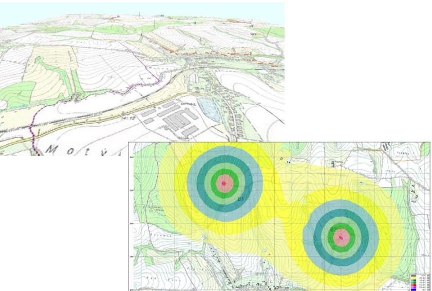
(images by P. Berková)
Figure8.83Dmodelandnoisebands–Industrialareaandbarriers (images by P. Berková)
Figure8.93Dmodelandnoisebands–Noisegeneratedbywindturbines
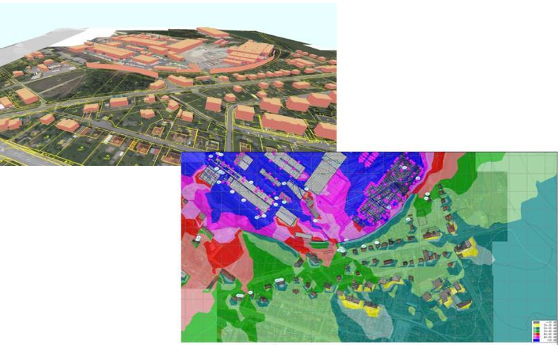
Sustainable Building Design 154
9OverviewofLEEDHomesGreenRating system
D-r Norbert Harmathy
A LEED ‘green’ building is a building that, in its design, construction or operation, reduces or eliminates negative impacts, and can create positive impacts, on our climate and natural environment. The LEED certification standards stand for a standardized design and measurement of the energy, water, sustainable and environmental efficiency of a building or neighbourhood. LEED stands for Leadership in energy and environmental design. The LEED certification was founded by the USGBC (United States Green Building Council). The slogan for LEED is ‘Better buildings equal better lives’ which reflects that sustainable green buildigns bring a more comfortable and heailthier environment for the users. Green buildings are the foundation of something bigger: helping people, and the communities and cities they reside in safely, healthily and sustainably thrive. [1,2]
9.1. LEEDstandardstructure

Residentialprojects
LEED is for all building types and all building phases including new construction, interior fit outs, operations and maintenance and core and shell. [3] This material will focus on residential projects only. The following standards are eligible for residential buildings.Neighborhood DevelopmentFor new land development projects or redevelopment projects containing residential uses, nonresidential uses, or a mix. Projects can be at any stage of the development process, from conceptual planning to construction. Includes: Plan and Built ProjectHomesFor single family homes, low-rise multi-family (one to three stories) or mid-rise multi-family (four to six stories). Includes: Homes, Multifamily Lowrise and Multifamily Midrise LEED ZeroAvailable for all LEED projects. LEED Zero is for projects with net zero goals in carbon and/or resources.
Sustainable Building Design 155
9.2. Creditcategories
The rating system evaluates the building in different categories, which are the following, Figure 8.1. [4]
Figure9.1LEEDcreditcategories
LEEDPerformance Path (LPP) for existing buildings:
LPP is a pathway to earn LEED for Existing Buildings (LEED EB) certification. In order to get certified, a building must meet all of the LEED v4 for Existing Buildings prerequisites and earn 40 or more of the 100 possible LEED credits. The main difference between LPP and a traditional LEED certification is that 90 of the 100 possible credits (or optional points) are earned based directly on how your building performs in the following five categories Fugure 2: [5] Energy (33), Water (15), Waste (8), Transportation (14), and Human Experience (20).
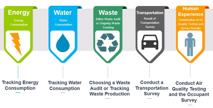
Figure9.2 LEEDPerformancePath[5]
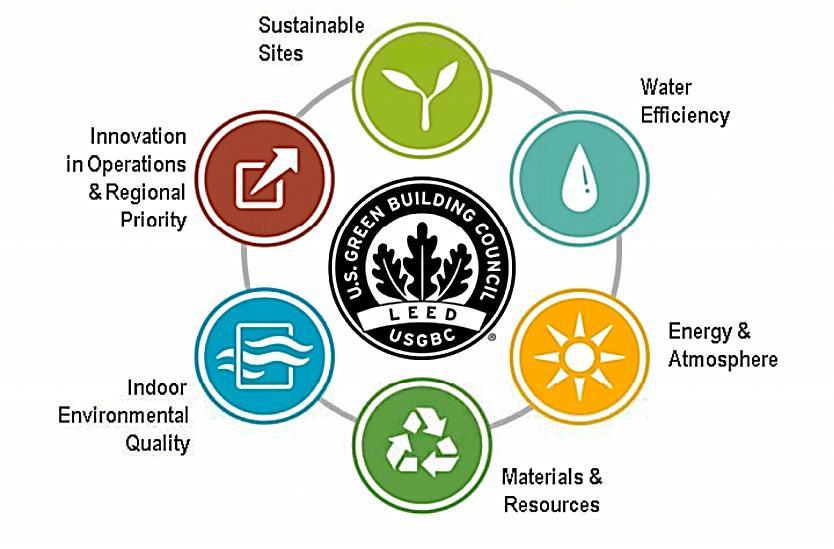
Sustainable Building Design 156
9.3. Energyperformance
The LEED credit categories with the most credits are the Energy and Atmosphere, and the Indoor Environmental Quality Category. The more energy efficient and healthy and comfortable a building is the higher rating system can be achieved. The intent of the Optimize energy performance is to achieve increasing levels of energy performance beyond the prerequisite standard to reduce environmental and economic harms associated with excessive energy use. [6] The requirements are to establish an energy performance target no later than the schematic design phase. The target must be established as kBtu per square foot-year (kWh per square meter-year) ofsource energy use. Three options are available:
Option 1. Whole-building
energy simulation
Analyze efficiency measures during the design process and account for the results in design decision making. Use energy simulation of efficiency opportunities, past energy simulation analyses for similar buildings, or published data (e.g., Advanced Energy Design Guides) from analyses for similar buildings. Analyze efficiency measures, focusing on load reduction and HVAC-related strategies (passive measures are acceptable) appropriate for the facility. Project potential energy savings and holistic project cost implications related to all affected systems. Project teams pursuing the Integrative Process credit must complete the basic energy analysis for that credit before conducting the energy simulation. [6] Credits are awarded according tot he cost reduction.
Option
2. Prescriptive compliance: ASHRAE Advanced Energy Design Guide
To be eligible for Option 2, projects must use Option 2 in EA Prerequisite Minimum Energy Performance. Implement and document compliance with the applicable recommendations and standards in Chapter 4, Design Strategies and Recommendations by Climate Zone, for the appropriate ASHRAE 50% Advanced Energy Design Guide and climate zone. For projects outside the U.S., consult ASHRAE/ASHRAE/IESNA Standard 90.1–2010, Appendixes B and D, to determine the appropriate climate zone. [6] ASHRAE 50% Advanced Energy Design Guide for Small to Medium Office Buildings Building envelope, opaque: roofs, walls, floors, slabs, doors, and continuous air barriers (1 point) Building envelope, glazing: vertical fenestration (1 point) nterior lighting, including daylighting and interior finishes (1 point) Exterior lighting (1 point) Plug loads, including equipment and controls (1 point)
9.4. IndoorEnvironmentalQuality
Indoor Environmental Quality (IEQ) encompasses the conditions inside a building air quality, lighting, thermal conditions, ergonomics and their effects on occupants or residents. Strategies for addressing IEQ include those that protect human health, improve quality of life, and reduce stress and potential injuries. Better indoor environmentalquality can enhance the lives of building occupants, increase the resale value of the building, and reduce liability for building owners. [7]
Sustainable Building Design 157
Whyisthisimportantforbuildings?
Since the personnel costs of salaries and benefits typically surpass operating costs of an strategies that improve employees’ health and productivity over the long run can have a large return on investment. IEQ goals often focus on providing stimulating and comfortable environments for occupants and minimizing the risk of building-related health problems. [7]
To make their buildings places where people feel good and perform well, project teams must balance selection of strategies that promote efficiency and conservation with those that address the needs of the occupants and promote well-being. Ideally, the chosen strategies do both: the solutions that conserve energy, water and materials also contribute to a great indoor experience.
Whatarecommonsourcesofindooraircontaminants?
People smoking tobacco inside the building or near building entrances or air uptakes Building materials such as paints, coatings, adhesives, sealants, and furniture that may emit volatile organic compounds (VOCs), substances that vaporize at room temperature and can cause health problems Combustion processes in HVAC equipment, fireplaces and stoves, and vehicles in garages or near entrances Mold resulting from moisture in building materials. Radon or methane off-gassing from the soil underneath the buildingPollutants from specific processes used in Pollutants tracked in on occupants’ shoes Occupants’ respiration, which increases carbon dioxide levels and may introduce germs [7] The best way to prevent indoor pollutants is to eliminate or control them at the sources. The next line of defense is proper ventilation to remove any pollutants that do enter. Both approaches need to be considered at allphases ofthe building life cycle. [7]
Whatareeffectivestrategiesimprovingoccupants’comfortand control?


Use daylighting. Install operable windows. Give occupants temperature and ventilation control. Give occupants lighting control. Conduct occupant surveys. Provide ergonomic furniture. Include appropriate acoustic design. [7] Examples of certified green buildings Some selected outstanding projects are presented worldwide which demonstrated very good and high energy efficiency.
9.5. LEEDforResidentialDesignandConstruction
Impact for renters, owners and the environment LEED helps create living spaces where people can thrive. LEED-certified homes are designed to provide clean indoor air and ample natural light and to use safe building materials to ensure our comfort and good health. They

Sustainable Building Design 158
help us reduce our energy and water consumption, thereby lowering utility bills each month, among other financial benefits. Using the strategies outlined in LEED, homeowners are having a net-positive impact on their communities. LEED homes are also designed, constructed and operated to be resilient in adverse conditions and are developed with proactive design planning for potential impacts of catastrophic weather. [3] Health: LEED homes are designed to maximize indoor fresh air and minimize exposure to airborne toxins and pollutants, making it healthier and more comfortable. Savings: LEED homes use less energy and water, which means lower utility bills. On average, certified homes use 20 to 30 percent less energy than non-green homes, with some homes saving up to 60 percent. Value: With proper planning, LEED homes can be built for the same cost as non-green homes. LEED homes can qualify for discounted homeowner’s insurance, tax breaks and other incentives. And in many markets, certified green homes are now selling quicker and for more money than comparable nongreen homes. For better homes, accountability makes a difference. Through a carefully managed, independent, third-party verification system, LEED-certification affirms the integrity of green building commitments by ensuring project teams are delivering on design plans and goals. Third-party validation helps guarantee that each project saves energy, water and other resources, reducing overallenvironmentalimpact.
9.6. HowCertificationWorks


Fornewprojects
Determine your project type (Single Family, Multifamily or Multifamily Core and Shell). Select your priorities. LEED credits allow project teams to customize how they pursue LEED (ex. health, energy and water efficiency, resilience, etc.). By fulfilling credits, project teams earn points that, once added together, determine a project’s certification level. Build your team. Goals and roles are key elements to consider when starting any project and it's no different in LEED. There could be several people who are members of the project team. All LEED residential project teams must include a LEED Green Rater (projects in the USA and Canada may also contact a Homes Provider organization). Deadlines. At any given time, a LEED rating system is either open for registration and certification, closed for registration but open for certification or sunset (closed for both registration and certification).
MajorCreditcategoriesforHomes
Major categories with the highest influence on the building perfroamce fist of all is the energy category where the intent is to improve the home’s overall energy performance and reduce its greenhouse gas emissions. The requirement is to design and construct a building whose modeled annual energy usage is lower than the LEED energy budget. The LEED energy budget
Sustainable Building Design 159
is based on the ENERGY STAR for Homes, HERS Index Target Procedure for National Program Requirements, version 3, with the following modifications: size adjustment factor is always 1, the building is a slab-on-grade ranch whose floor area is equal to the ENERGY STAR reference home’s conditioned floor area, there are no floors over unconditioned spaces, there are two exterior half-lite doors, unshaded, one on the south wall, one on the west wall, the glazing is 15% of the floor area, the ceiling is insulated, and its gross area equals the conditioned floor area. the storage water heater has an energy factor of 0.59 for gas, 0.92 for electric, the thermal distribution system is 100% in the attic, above insulation. Balancing of heating and cooling distribution systems has the intent to improve thermal comfort and energy performance by ensuring appropriate distribution of space heating and cooling in the home. For Option 1. Multiple Zones the owner has to install a system with at least two spaceconditioning zones with independent thermostatic controls. In houses with both a heating system and a cooling system, each must have at least two zones. Single-family houses with less than 800 square feet (74 square meters) of conditioned floor area and multifamily buildings whose average unit size is less than 1,200 square feet (110 square meters) automatically meet the requirements of this credit. For Option 2. Supply Air-Flow Testing: Have the total supply air-flow rates in each room tested using a flow hood with doors closed, or another acceptable method, per RESNET or ACCA Quality Installation Specifications. Supply air-flow rates must be within +/- 20% (or +/- 25 cfm or 11 lps) of calculated values from ACCA Manual J. Test multirate or multispeed HVAC systems at the rate for which they were designed. Supply air-flow requirements must meet the higher of the cooling or heating designed air flow for each room. Ductless systems qualify for this credit. For Option 3. Pressure Balancing (1 point) for each bedroom, demonstrate a pressure difference of less than 3 Pa (0.012 inch w.c.) with respect to the main body of the house when doors are closed and the air handler is operating on highest speed. [3]
The intent for single family housing projects is to minimize indoor demand for water through high-efficiency fixtures and fittings. Install fixtures consuming more than 2.5 gallons per minute (9.5 liters per minute) per shower compartment must use WE Credit Total Water Use. Each lavatory faucet or faucet aerator must be WaterSense labeled. The average rated flow volume across all lavatory faucets must not exceed 1.5 gallons per minute (5.6 liters per minute) for 1 point or 1.0 gallons per minute (3.7 liters per minute) for 2 points. Each showerhead fixture and fitting must be WaterSense labeled. The average rated flow volume per shower compartment must not exceed 1.75 gallons per minute (6.6 liters per minute) for 1 point or 1.5 gallons per minute (5.6 liters per minute) for 2 points. Each toilet fixture and fitting must be WaterSense labeled. The average rated flush volume across all toilets must not exceed 1.1 gallons (4.1 liters) per flush (1 point). Each clothes washer must be ENERGY STAR qualified or performance equivalent for projects outside the U.S. (1 point) The water pressure in the house must not exceed 60 pounds per square inch (414 kPa), with no detectable water leaks. For projects outside the United States, a local equivalent to WaterSense may be used.
Sustainable Building Design 160
The second important category is the efficient hot water distribution where the intent is to design and install an energy-efficient hot water distribution system, based on either maximum pipe length requirements. The source of hot water is assumed to be a water heater, boiler, circulation loop piping, or electric heat-traced piping. Multiple water heaters and multiple distribution systems may be used to comply with this credit. Systems that use heat traces that serve a single unit or house are awarded only half credit. All heat traced piping mustbe insulated. Afterwards the renewable energy category has the intent to design and install a renewable electricity generation system. Receive 1 point for every 500 kWh produced per year by the system. The maximum allowable points for this credit is equivalent to the total points earned from all other credits. Renewable energy certificates (RECs) must be retained by the building owner.
Environmentally preferable products are also prioritizes where the intent is to increase demand for products or building components that minimize material consumption through recycled and recyclable content, reclamation, or overall reduced life-cycle impacts. Use products that meet one or more of the following criteria. At least 90% of each compliant building component by weight or volume, must meet one of the requirements. A single component that meets more than one criterion does not earn additional credit. These requirements are that the product contains at least 25% reclaimed material, including salvaged, refurbished, or reused materials. For renovation projects, existing components are considered reclaimed. Wood by-products can be counted as reclaimed material. These include items from secondary manufacturers; felled, diseased, or dead trees from urban or suburban areas; orchard trees that are unproductive and cut for replacement; and wood recovered from landfills or water bodies. The product contains at least 25% postconsumer or 50% preconsumer content. Wood products must be Forest Stewardship Council (FSC) Certified, or USGBC-approved equivalent. Bio-based materials. Bio-based products must meet the Sustainable Agriculture Network’s Sustainable Agriculture Standard. Bio-based raw materials must be tested using ASTM Test Method D6866 and be legally harvested, as defined by the exporting and receiving country. Exclude hide products, such as leather and other animal skin material. Concrete that consists of at least 30% fly ash or slag used as a cement substitute and 50% recycled content or reclaimed aggregate OR 90% recycled content or reclaimed aggregate. Extended producer responsibility. Products purchased from a manufacturer (producer) that participates in an extended producer responsibility program or is directly responsible for extended producer responsibility [3] Air quality is also a major issue. The LEED requirement demand to install air filters with a minimum efficiency reporting value (MERV) of 8 or higher on all recirculating space conditioning systems, per ASHRAE 62.2–2010. Design ductwork and specify the central blower to account for the pressure drop across the filter. Air filter housings mustbe airtight to prevent bypass or leakage. Nonducted systems are exempt from the minimum MERV 8 requirements but must have an internal air filter in the air-handling unit. Install air filters rated MERV 6 or higher for mechanically supplied outdoor air for systems with 10 feet (3 meters) of ductwork
Sustainable Building Design 161
or more, per ASHRAE 62.2–2010, Section 6.7. Projects may use equivalent filtration media class of F5 or higher for MERV 8 and G4 or higher for MERV 6, as defined by CEN standard EN779 2002. [3] Projects that earn the EPA Indoor airPLUS label automatically meet the requirements ofthis prerequisite.
Sustainable Building Design 162
10 SustainableHVACsystems
D-r Aleksandar Andjelkovic
10.1. Introduction
“Buildings consume 30%–40% of the yearly primary energy in developed countries, and approximately 15%–25% in developing countries” [1]. “In the residential sector, space heating uses 20–50% and DHW, 10–20% of the totalbuilding energy consumption” [2]. In the UK, 49% of annual carbon emissions are attributable to buildings. According to the London Energy Transformation Initiative (LETI) report over the next 40 years, the world is expected to build 230 billion square meters of new construction, adding the equivalent of Paris to the planet every single week [3] “So we must act now to meet the challenge of building net-zero developments” [3]. Energy consumption in the residential sector primarily depends on the building type, building construction (building shape and orientation and construction materials), Heating, Ventilation, and Air Conditioning systems (HVAC), and climate conditions. The efficiency of the equipment and appliances used in residential buildings has increased greatly over the past three decades. However, there is still much that can be done to reduce the amount and slow the growth ofenergy consumption in this sector.
10.2.HVACsystemsforresidentialbuildings
“As normal resources swiftly exhaust around the world, the want for green or environmentally responsive building practices is becoming supplementary and more perceptible. So-called “green buildings” are constructed or refurbished under sustainable expansion, a design process that condenses the detrimental impact on natural resources and looks at the lifecycle costs of the facility” [4]. The benefits of designing and constructing green buildings are significant and easy to comprehend. First, comparing to conventional constructing residential buildings, green buildings have lower operating costs. Second, sustainable design helps in decreasing GHG emissions, ozone layer depletion, and excess water usage. Third, residents feeling healthier and happier when they are living in well-lighted, properly ventilated, and thermally conditioned living spaces.
HVAC systems are targets for sustainability improvements in many facilities because of the high costs related to their installation, operation, and maintenance. A properly designed and installed HVAC system can provide years of comfort for occupants, lower energy bills, and improved water consumption. But a lack of proper planning can jeopardize material costs for
Sustainable Building Design 163
preventive maintenance activities, energy costs, and occupant comfort. According to [4] in the majority state ofaffairs, HVAC systems willsignificantly impact how “green” building is.
Designing a sustainable, efficient HVAC system for residential buildings is not only a challenge for mechanical engineers but also for architects, structural and civil engineers as well. Collaboration between mechanical engineers and other engineers throughout all designs phases is necessary if we want to design the net-zero building (Integrated Sustainable Building Design). Applying ISBD allows designers to deal with crucial details about architectural design, building structure, and HVAC systems in the early stage of the design process. In this way, design errors are kept to a minimum. While designing the building architects should thoroughly analyze building orientation and envelope design (structure type and applied materials). Properly oriented buildings constructed from low U-values materials can significantly reduce heating and cooling loads. Also, the building should be designed to allow maximum daylight utilization and maximum use of natural ventilation. Further, the building should be design to meet the Indoor Air Quality and Indoor Environment Quality requirements. In the end, architectural and structural building design should allow the use of renewable energy sources (RES) and HVAC systems based on “green” technologies. There are many available principles, rules, and recommendations on how to design the building. Fanney and Healy, In their report [5], proposed ten principles for designing a residentialbuilding:
1) Design for comfort and function;
2) Establish an airtight building enclosure; 3) Provide controlled ventilation;
4) Incorporate insulation that exceeds presentenergy code requirements; 5) Ensure the building enclosure controls water and moisture movement;
6) Orient the building to maximize renewable energy production;
7) Select efficient mechanical equipment;
8) Select efficient lighting, plumbing fixtures, and appliances;
9) Use energy modeling to predict total energy use, size of on-site renewables, and identify high-value improvements to energy efficiency;
10) Develop project plans that coordinate and commission systems.
A residential sector can roughly be divided into three subsectors: small, medium, and largescale residential buildings. For each subsector, specific energy sources and HVAC design can be defined. The most common energy sources for all three subsectors are natural gas, electricity, and RES. There is a variety of energy uses in a residential building: space heating, domestic hot water (DHW) production, space cooling, mechanical ventilation and air handling, electric lighting, and plug loads [6]. Based on previous, HVAC systems used for small-scale (SSRB) and medium-scale (SMRB) residentialbuildings can be divided into [6]:
• Integrated systems for space heating and DHW;
• Integrated systems for space heating, cooling, and DHW;
Sustainable Building Design 164
For large-scale residential buildings (LCRB) mostcommonly used system for heating, cooling, and DHW is the district heating/cooling system (DHC).
IntegratedsystemsforspaceheatingandDHWSSRBandSMRB
Gasorelectricboiler
One of the most accepted and characteristicsystems for space heating and DHW production is wall-mounted gas or electric boiler. “Over the years, the efficiency of these systems increased significantly. In particular, the condensing boiler technology appears attractive in virtue of its potential to go beyond 100% efficiencies, measured on the lower heating value, exploiting condensation heat from the fuel combustion” [6]. To reduce fossil fuel consumption gas boilers can be connected to the solar panel system allowing space heating and DHW on a high and low thermalenergy level(Figure 2.1).
Heatpumpwithacondensingboiler
Heat pump systems are grounded as one of the most used RES-based HVAC systems for heating, cooling, and DHW in small and medium-scale residential buildings. Heat pumps allow transferring thermal energy from a low-temperature medium to a high-temperature medium. A heat source is used as a medium to extract thermal energy through an evaporator and a heat sink is used as a medium to reject thermal energy through a condenser. The energy sources for heat pumps are air, water, ground, or geothermal energy, and based on that they are classified. Due to the inconstant temperature of the energy source, especially in the case of air-to-water/air heat pumps, the efficiency of these systems can significantly vary during the season. Most of the past studies were conducted on heat pumps as stand-alone systems, while new researches are currently more oriented to the integration of heat pumps with other energy systems [7]. Heat pump hybrid systems have reduced costs and improved energy efficiency compared to conventional systems. One of the characteristic hybrid systems with a heat pump is shown in Figure 2.2. The heat pump runs when temperatures are mild. When the outside air temperature decreases, the heat pump's coefficient of performance (COP) decreases, while the heating load increases and the boiler is used since it is more convenient in terms of energy efficiency. Integrated system (1) shown in Figure 2.2 contains an air-to-water heat pump (6-8 kW), condensing boiler (3.333 kW), a 300l stratified water heater, solar panels, and PV solar system. According to [6] the average seasonalenergy efficiency ratio ofsuch a system amounts to 127%.

Sustainable Building Design 165
Figure10.1
Schematicofacondensingboilerconnected tothesolarpanelcircuit
Figure10.2
Schematicofair-to-airheatpump,condensingboiler, solarpanel,andPVpanel
Solarsystemcombinedwithair-to-waterheatpump (SAHP)
Another hybrid system that can produce energy for space heating and DHW is shown in Figure 2.3. Heat is generated both in the air-to-water heat pump and solar panel circuit and stored in a tank (e.g. 750 l hot water for space heating and 200 l for DHW), and used for radiant heating and DHW production.
Figure10.3Schematicofasolarpanelcircuitconnectedtotheheatpump
Integratedsystemsforspaceheating,cooling,andDHWforSSRBand SMRB
Reversibileheatpump
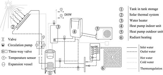
Fabrizio et al. stated that the most recurring solution integrating space heating, DHW and space cooling is based on the reversible heat pump technology [6]. “Recent upgrades led
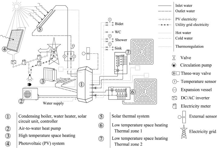
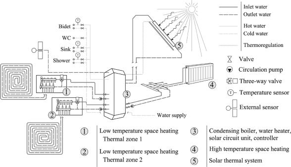

Sustainable Building Design 166
heat pumps to produce, along with hot and chilled water for space heating and cooling, also hot water for domestic use at appropriate thermal levels” [6]. The same authors pointed that for low energy demand users, reversible heat pumps with heat recovery are currently very commonly adopted, operating on “single-stage” (space heating or space cooling or DHW) and “two-stage” (space heating and DHW, space cooling, and DHW with heat recovery).
Table 2.1 and Figure 2.4-2.5 are showing thermal capacity and seasonal COP and EER variations for different condenser outlet temperatures, water source temperature, and outside air temperatures.
Table10.1.Water-to-waterandair-to-waterheatpumpseasonalCOPandseasonalEERaccordingto differenthot/chillerwatersupplytemperatures [6]
Tout(°C) Water-to-waterheatpump
Air-to-waterheatpump SCOP SEER SCOP SEER 35 5.70 3.76 45 4.72 3.35 18 5.48 5.23 7 4.59 4.02
Figure10.4
COPvariationinrelationtothewatersource temperatureaccordingtovaryingloadsforasmall capacitywater-to-waterheatpump/refrigeratorfor residentialapplications
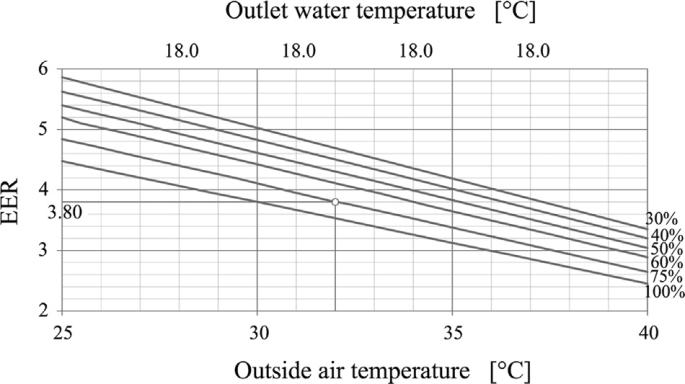
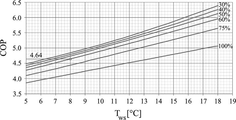
Figure10.5
EERvariationinrelationtotheoutsideair temperatureaccordingtovaryingloadsforasmall capacityair-to-waterheatpump/refrigeratorfor residentialapplications
VariableRefrigerantVolume(VRV)orVariableRefrigerantFlow (VRF)system
Another system for space heating, cooling, and DHW production is VRV or VRF system. A VRF system exploits a variable speed compressor and the indoor unit's electronic expansion
Sustainable Building Design 167
valves to vary the refrigerant flow rate to cover the heating and cooling loads and reach the set-point temperature.
Summarized data about system type, capacity, efficiency, strengths, and weaknesses of the above-mentioned HVAC systems for small and medium-scale residential buildings are shown in Table 9.2. For all previously described systems ventilation system with possibility for the heat recovery is acceptable.
Table10.2HVACsystemreviewforsmallandmedium-scaleresidentialbuildings
Energy system Energy input Energy output
Smallsize gasboiler Gas, (solar)
Heating/Cooling/ Electricity Capacity Design Efficiency
Space heating, DHW Upto24kW >1.00
Strengthsand advantages Weaknessesand drawbacks
Low-temperature space heating (e.g., in-floor radiant panels); Optimal performances at low return temperatures; Instantaneous DHWproductionor through integratedstorage tank; Integration withsolarthermal
Non-renewable energy source; Hightemperature space heating(e.g.,radiators)
Heat pumpCondensing boiler
Electricity from grid, solar, gas
Space heating, DHW, (space cooling)
3.3–33kW condensing boiler;6–8kW heatpump Upto1.27
Upgrading of the heat pump performances; Maximization of theenergysystem total efficiency; Flexibility: peak loads can be covered by the condensing boiler above the cut-off temperature; integrated or separate set-up; different heat pumps types are suitable (also absorption heat pumps); Potentiallyclosedcycleifintegrated withPV
Complex integrated design
SAHP
Electricity fromthe grid, solar
Space heating, DHW, (space cooling)
8-16kW
3.9–4.2COP (35°Cwater supply temperature); 4.20–4.50EER (18°Cwater supply temperature)
Appropriate for detached houses; Maximization of renewable energy exploitation; Variety of available technologies; Evaporator–collector
Centralized storage and integrations are neededinmulti-family residentialbuildings
Sustainable Building Design 168
Reversible heatpump
Electricity from the grid, (solar)
Space heating, DHW, space cooling
5-20kW
5.70 SCOP (35°C water supply temperature)
5.48 ESEER (18°C water supply temperature) – Depending onthedesign conditions
efficiencies are higher than the one of conventional collectors; Potentiallyclosedcycle if electricity isprovidedbyPV
Widely used solution for space heating and cooling; Recently also DHW can be produced with heat recovery; Integration with solar thermal; Potentiallyclosedcycleifintegrated; with PV; Optimal performance at lowerloads
Dependence on the outdoor-indoor temperature gradient; Potential mismatch betweenexpectedand real operating conditions (evaporator/condenser source side temperature, ΔT); Lack of data from manufacturers on operating conditions different from referencepoints
VRF/VRV
Electricity from the grid, (solar)
Space heating, DHW, space cooling
From12.5kWup (heating) from 1.2 kW up (cooling)
2.5–5 COP dependingon design conditions

Energy performance and cost effectiveness; The indoor unit refrigerant flow rate can be calibrated on the cooling loads; Integration with solar thermal; Heat recovery from thermal zonesunderspace cooling for the integration of hot waterproduction
Limited hot water thermal level (45°C); Superheats in indoor units and compressor speed should be carefullydesigned
HVACsystemforlarge-scaleresidentialbuildings
As was mentioned for large-scale residential buildings most commonly used system for heating, cooling, and DHW is the district heating/cooling system (DHCS). A district heating (DHS) system is a system that produces heat, in the form of hot water and superheated steam, from a central power plant using gas, renewable energy, or waste heat. The produced heat is distributed via the DH distribution system (pipe network) to the district heating substations and the end-users. DH system efficiency is around 85%. Combining with electricity production (Combine Heat and Power-CHP) efficiency can increase up to 92%. Additionally, applying the fourth generation DHS will increase the efficiency of the existing systems. The fourth-generation DHS is a concept that applies modern smart, sustainable
Sustainable Building Design 169
systems and renewable energy sources to upgrade existing systems. It provides an optimum energy supply with low production and grid losses. A district cooling (DC) network is a centralized system that provides chilled water to supply an air conditioning system. In practice, it includes chilled water production and distribution facilities to provide cooling services to all connected buildings.Numerous studies into the improvement of the destring heating and cooling system efficiency were conducted [8]
10.3.Feasibilitystudyindesigningnet-zeroresidentialbuilding
The study was based on a real-world project, a residential block, that was in the concept design stage at the time of publishing and it was conducted by the UK Green Building Council (UKGBC) [9]. The study was done for three different design scenarios: baseline scenario (represents business as usual levels of building performance), intermediate scenario (uses net-zero targets for 2025 to represent buildings that are in or will soon be in design), stretch scenario (uses net-zero targets for 2030 to represent design changes that may be seen as challenging today but will need to become the norm over the next decade) [9]. During the study, key design changes were made in building structure, facade, building HVAC systems, and apartment design. Regarding structure, changes were made in the superstructure, substructure, and concrete mix. Facade changes were oriented toward reducing glazing ratio and using triple-glazed transparent surfaces with lower U-values [3], [9], using thermodynamically more efficient insulation and envelope materials [9]
The baseline scenario design for the HVAC systems uses a traditional gas boiler to produce low-temperature hot water at 70°C with an efficiency of 95% for both space heating and domestic hot water. Mechanical ventilation with heat recovery (MVHR) with a heat recovery efficiency of 85% is included for all scenarios. The intermediate design utilizes an air source heat pump (ASHP) in place of the gas boiler. The air source heat pump generates lowtemperature hot water at 45°C. This is distributed to the dwellings for space heating and is typically uplifted to 60°C for domestic hot water by an electric immersion heater in the hot water cylinder. The anticipated annual COP for heating is 3.22 and for domestic hot water (DHW) 2.06. COP was anticipated based on the manufacturer efficiency profiles, local weather data, heating loads, and DHW loads [9]. The stretch design includes the same ASHP as the intermediate design, introduces additional energy recovery technologies, and assumes improved lighting and appliance efficiencies. A chemical treatment method, such as a chlorine dioxide dosing system, is incorporated which allows the storage of domestichot water at 45°C (negating the need for temperature-based legionella control). Applying this water treatment method annualCOP of 3.77for the DHW system is achieved [9].
Apartment design changes refer to the type and efficiency of the white goods and appliances and unregulated loads (Table 9.2) [9].
Sustainable Building Design 170
Appliances
Table10.3Apartmentdesignchanges
Baselinescenario Intermediatescenario Stretchscenario
Occupier choice of white goods and appliances
Occupier choice of white goods and appliances AAA-whitegoods and bestappliance
Unregulatedloads 38 kWh/m2 38 kWh/m2 29 kWh/m2
After the design changes study phase, the cost analyses phase was conducted. Applying all the above-mentioned changes will result in the cost changes between the baseline scenario and the other two net-zero design scenarios. Costchanges for the HVAC system are shown in Table 3.2 [9].
Table10.4CostchangesfortheHVACsystem
Baselinescenario Intermediatescenario Stretchscenario
£/m2 £/m2 % change from baseline £/m2 % change from baseline
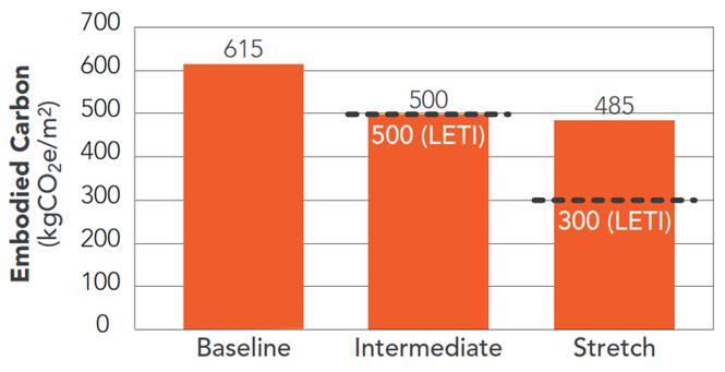
HVAC system 580 590 2% 625 8%
The following Figures 9.6-9.7 provide a summary of results for the three design scenarios alongside a comparison with relevant net-zero targets is provided [9]
Figure10.6EmbodiedCarbon- studyresultscomparisonwithnet-zerotargets
Sustainable Building Design 171
Figure10.7Reductionsinoperationalenergy
These results show that the intermediate target is just achievable. It is however extremely challenging for the stretch target to be met. The stretch scenario falls short of the RIBA target despite an 80% reduction in regulated loads (74 kWh/m2 in the baseline, 15kWh/m2 in the stretch design). The target can only be met with reductions in unregulated loads [9].
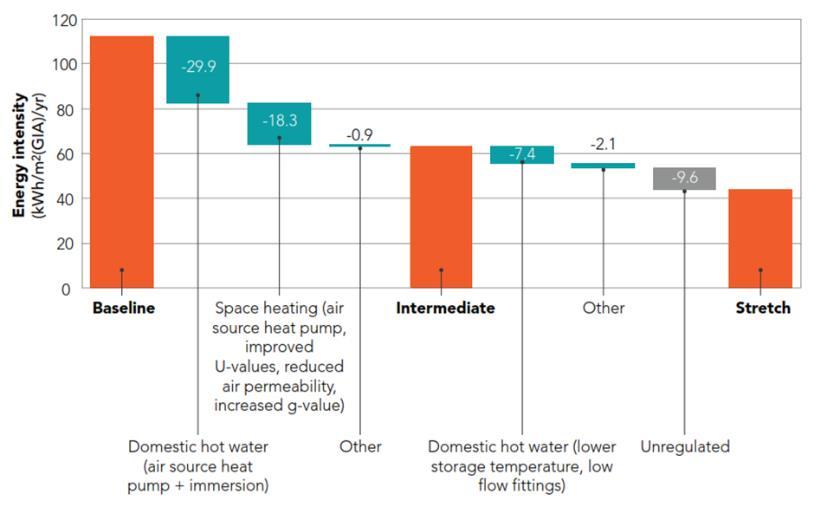
10.4.Conclusions
HVAC systems are the biggest energy consumers in residential buildings. Due to that fact, GHG emissions are for this building type are significant. As it was mentioned in the paper, HVAC systems are targets for sustainability improvements. An integrated and complete design process commencement at a project’s inception is requisite to optimize the HVAC design and maneuver for green buildings. A properly designed HVAC system will result in lower energy consumption and lower carbon emission both operational and embodied. Designing a residential net-zero building is still a novel principle. The targets for GHG emissions reduction and energy efficiency improvements are setbut still difficult to achieve.
In the paper detailed review of the HVAC systems for small, medium, and large-scale residential buildings is presented. The most commonly used HVAC designs are described with a detailed overview of the design capacities, system efficiencies, energy inputs and outputs, system strengths and weaknesses. Besides that, recommendations for architects and civil engineers are provided. Also, a feasibility study in designing net-zero residential buildings was shown. Results of the study showed that for the baseline and the intermediate scenario is possible to meet set up targets for embodied carbon. The same case is for operational energy. Achieved operational energy for the baseline and intermediate scenario met the designated targets while the stretch scenario falls short of the RIBA target despite an 80% reduction in regulated loads.
Sustainable Building Design 172
11 CircularEconomy
D-r Natasa Simeunovic
There is only one planet Earth, but by 2050, 9 billion people will be living here and will be consuming as if there were three Earths [1], [2]. Global consumption of such materials as biomass, fossil fuels, metals and minerals is expected to double over the next forty years, meanwhile annual waste generation is expected to increase to as much as 70% by 2050 [2]. At the same time, we live in a time of enormous economic inequalities between people and societies, accelerated environmental degradation, climate change and social inequalities. It is obvious that current economic models, whose ultimate goal is economic growth at any cost [3], measured in terms of gross domestic product (total and per capita), are not sufficient to achieve a better distribution of wealth, economic equality and well-being, and their prioritization ofeconomic growth has a negative impact on the environment [4].
Since the early 2000s, different economic models have been promoted that are designed to achieve social equality and inclusion, to stop environmental degradation and to stimulate environmental regeneration while maintaining economic productivity. Some of these are well known - green, blue and circular economy, while others have emerged more recentlyregenerative economy and doughnut economics.
The circular economy is a fairly well-known concept dating back to the 1960s and 1970s. However, it has gained popularity and application since the late 2000s. The concept was developed as a contrast to the still dominant linear economy model in which the raw materials are extracted from the environment during production and processed into new products that are eventually discarded into the environment [5]. Raw materials are not infinite and eventually run out, while waste accumulates and drives up the cost of its disposal or pollution (Fig. 10.1).
Sustainable Building Design 173
Figure11.1ConstructionCircularEconomyModel[6]
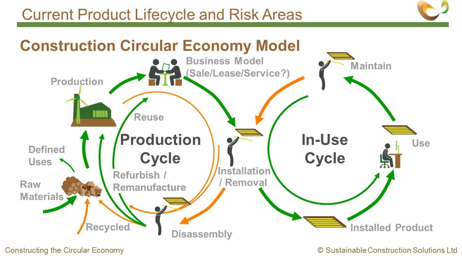
More than 100 different definitions of circular economy are used in scientific literature and professional journals. There are so many different definitions in use, because the concept is applied by a diverse group of researchers and professionals [7]. A philosopher of science emphasizes a different aspect of the concept than a financial analyst. The diversity of definitions also makes it more difficult to make circularity measurable.
Definitions often focus on the use of raw materials or on system change. Definitions that focus on resource use often follow the 3-Rapproach:
• Reduce (minimum use ofraw materials)
• Reuse (maximum reuse ofproducts and components)
• Recycle (high quality reuse of raw materials)
Mobility can serve as a good example. Sharing cars, from companies such as MyWheels and WeGo, mean that fewer people have to buy their own cars. This reduces the use of raw materials (reduce). If the engine of a car is broken, it can be repaired or the chassis and interior of the car can be used to make or refurbish another car (reuse). When these parts can no longer be reused, the metal, textile and plastic of the parts can be melted down so that a new car can be made ofthem (recycling) [8].
According to Korhonen, Nuur, Feldmann & Birkie [9], definitions that focus on system change often emphasize three elements:
• Closed cycles
• Renewable energy
• Systems thinking
Sustainable Building Design 174
A circular economy is based on the principles of designing out waste and pollution, keeping products and materials in use, and regenerating naturalsystems [10]
The circular economy, as such, is seen as a new way of creating value and prosperity, by extending the life of products and moving waste from the end to the beginning of the supply chain. It uses two different cycles – biologicaland technological. The biological cycle refers to the consumption of food and bio-based materials designed to be returned to the environment through composting and anaerobic digestion processes (e.g., wood products), or transformed into energy. The technological cycle involves the design of products that can be reused and restored as whole products, components, and resources (e.g., buildings, airplanes...) [10] In other words, in the circular economy, products are manufactured in such a way that they can be disassembled and materials can be broken down by nature or returned to nature, with the goalofnot throwing anything away and reducing the need to buy new goods [11]. Ultimately, resources are used more efficiently by using them more than once, which should lead to less waste [5]
On the supply side, the circular economy focuses mainly on production chains in: electronics and ICT, batteries and vehicles, packaging, plastics, textiles, construction and buildings, and food, water and nutrients. While looking from the demand side, it should provide citizens with high-quality, functional and safe products that are efficient, affordable, last longer and are designed for reuse, repair and high-quality recycling [2].
11.1. Circularconstruction
Circular construction, the application of the circular economy to the construction industry, aims to close building material loops by reusing, sharing, leasing, repairing, refurbishing, upcycling or recycling rather than continuing the traditional take-make-consume-dispose process. It is about considering how to maximise the lifespan and reusability of entire buildings or materials at the very start of the design process (Fig. 2).
A true circular building is made of components of fully recyclable, non mixed technocycle materials, that can be 1 on 1 upcycled in the end of life (e.g. concrete columns), combined with building components that are fully fitting with the biocycle (e.g. prefab CLT components) that may recycled and even downcycled (particle board, bio-energy). Also it is important to use as many fully non-toxic materials as possible, proven by C2C (Cradle to Cradle) Gold / Platinum certification [13]. Ideally these building components are leased and there is an accurate overview of the materials used in a Material Passport of the building, this way a building becomes a material bank as shown in the BAMB2020 project [14]. In the Netherlands, Venlo City Hall [15] and Circl Pavillion [16] ABN AMRO bank Amsterdam WTC are showcases of a circular building project.
Sustainable Building Design 175
Figure11.2CircularConstructionActions[12]
Specifically, this applies to contractors and manufacturers of key materials and building elements along with designers. If known, the end user and/or the building/estate management provider should also be engaged. This is especially important to determine the lifecycle implications of the design approach, for example:
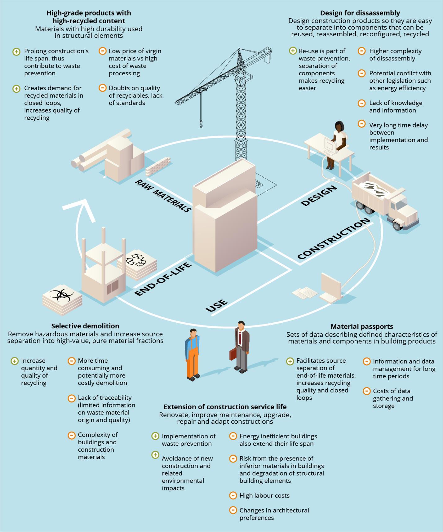
➢ How the building willbe maintained?
➢ What is the available budget?
➢ Is there an operational cost benefit from a circular approach?
Sustainable Building Design 176
Where possible, partnerships should be sought with integrated teams that have sustainability as a primary mission. Initial outcomes and objectives for the development should be revisited periodically through focused workshops and reviewed regularly at key stages.
Scarcity of resources and the need to reduce the environmental impacts of winning and processing construction materials and products is placing a greater emphasis on resource efficiency within the construction industry. It is estimated that the UK construction industry consumes some 400Mt of materials annually and generates some 120Mt of (construction, demolition and excavation) waste, of which 5Mt ends up in landfill. [17] Therefore, there is significant scope for improving resource efficiency within the industry, particularly at the endof-life ofbuildings.
The benefits ofrecycling are wellunderstood and include:
▪
Reducing waste, i.e. diverting waste from landfill ▪
Saving primary resources, i.e. substituting primary production ▪
Saving energy and associated greenhouse gas emissions through less energy intensive reprocessing.
Although these benefits apply to many commonly recycled materials, there are some important differences in the properties of materials that influence the environmental benefit ofrecycling and particularly how these benefits are quantified.
Metals, for example, are infinitely recyclable, i.e. they can be recycled again and again into functionally equivalent products - this is the most environmentally beneficial form of recycling.
Other products are ‘down-cycled’ into new products that are only suitable for lower grade applications because the recycled product has different, usually lower, material properties. Although waste is diverted from landfill by down-cycling, only lower grade primary resources are saved. For example crushing bricks and concrete for hardcore, sub-base or general fill saves aggregates but doesn’t save the resources required to make new bricks or new concrete.
For recycling to be sustainable in the long term, it is important that the recycling process is financially viable. This is frequently the biggest hurdle to recycling, particularly for products and materials that are down-cycled into lower grade, low value applications.
According to vand den Berg & Durmisevic [18] at this time of diminishing of resources and increase of environmental problems, it has become crucial to understand the capacities of buildings to transform a negative environmental impact of built environment to a positive one. The question is: how does one transform the current linear approach to design of buildings that has one ‘end-of-life’ option (demolition) to a circular design solution that will guarantee multiple life options of the building as well as of its systems, products and materials? Durmisevic has suggested that this can be achieved by systematically considering independence and exchangeability of building systems/components in three
Sustainable Building Design 177
dimensions of transformation (1) dimension of spatial flexibility of building; (2) dimension of technical flexibility of systems and product; and (3) dimension for material flexibility that can make a transition from a linear to circular building. Buildings designed with three dimensions of transformation open opportunities for a great palette of new value propositions of buildings and its systems, products and materials. Those buildings are called reversible buildings.
“Reversibility” is defined as process of transforming buildings or dismantling its systems, products and materials without causing damage. Building design that can support such processes is reversible (circular) building design (RBD) and can be seen as key ‘accelerant’ of Circular Economy in construction. Reversible Building Design is therefore seen as a design that takes into account all life cycle phases of the building and focuses on their future use scenarios. Design solutions that can guarantee high reuse potential of the building, systems, products and materials and that have high transformation potential are described as reversible. A key element of RBD is design for disassembly, which allows for easy modifications ofspatialtypologies and disassembly ofbuilding parts [19].
Current end-of-life scenarios for three of the most common construction materials; concrete, timber and steelare shown in Fig. 10.3with explanations of outcomes given in Fig. 10.4.
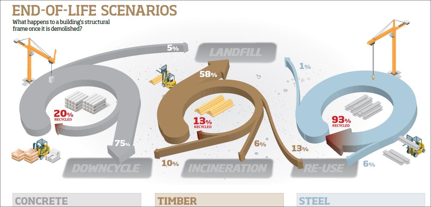
Figure 11 3 End-of-life scenarios [17]
Figure11.4End-of-lifescenariosoutcomes
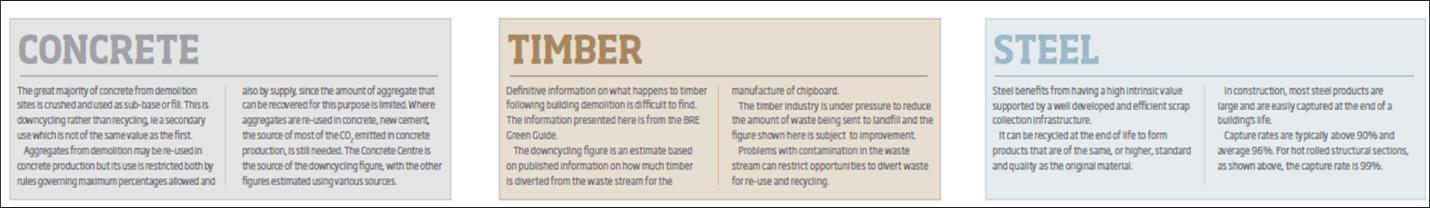
Sustainable
178
Building Design
11.2. LifeCycleCostingAnalysis

Life-cycle cost analysis (LCCA) is an economic method of project evaluation in which all costs accumulated from all life stages of a building are considered as potentially important to the decision. Those life stages include construction, operation, maintenance, and demolition. LCCA provides significantly better assessments of the long-term costefectiveness of renovation investment than alternative economic methods that only focus on initial costs [20]. Furthermore, LCCA helps to compare and determine which energy renovation strategies are economically justified from the investor’s (i.e., client’s) perspective based on energy consumption reduction and other costmeasurements [21]. The life cycle cost (LCC) can be calculated either in present-value or annual-value terms. Present-value terms require all future costs to be discounted to their present-value equivalent while the latter method amortizes those future costs evenly over the study period [22].
The generalformula used for the LCC present-value modelis Equation (1): LCC = IC + RepC + OC + MRC (1)

Where:
- LCC equals the total life-cycle cost in present-value dollars of a given renovation scenario (RS).
- IC indicates the present-value investment costs, - RepC is the present-value capitalreplacement costs, - OC is the present-value operating energy cost, and - MRC is the present-value maintenance and repair costs.
InvestmentCosts(IC)
The investment costs include allcosts spent on:
(1) the building systems (structure, HVAC, building envelope, etc.); (2) the process of producing, transporting, and assembling all building components onsite; (3) installation labor; and (4) the utilities and energy spent on construction.
Replacementcosts(RepC)
Replacement costs are the planned expenditures for major building systems, such as heating ventilation air-conditioning (HVAC) systems and water supply systems, to keep the building
Sustainable Building Design 179
in operation. RepC is to be discounted to its present value, prior to the addition of the LCC total, using Equation (2) [20]
���� =∑ �� (1+��)�� �� ��=1
Where:
(2)
- d is the discount rate (interestrate), - t is the year, and - n represents a specificyear when the presentvalue is calculated.
- PV indicates the presentvalue and - F is the future case amount occurring at the end of the year n [22].

The NIST takes the definition of discount rates a step further by separating them into two types: real discount rates and nominal discount rates. The difference between the two is that the real discount rate excludes the rate of inflation and the nominal discount rate includes the rate of inflation. This is not to say that real discount rates ignore inflation, their use simply eliminates the complexity of accounting for inflation within the present value equation. The use of either discount rate in its corresponding present value calculation derives the same result.
For instance, if the discount rate is 5%, then the present value of a cash amount of $78.35 today receivable at the end of the fifth year will be $100. For a decision-maker, those two amounts are time equivalent. Therefore, they will not have a preference between $78.35 received today and $100received at the end offive years.
Operatingcosts(OC)
Operating costs include the cost of normal electricity use, water consumption, and other expenditures, such as custodial and insurance. Operating costs are annual costs that exclude maintenance and repair and other costs not directly related to the operation. The value is also adjusted to the presentvalue using Equation (3): ���� =����(1 (1+��) ��) ��
(3)
where:
- d is the interestrate (%),
- n is the study period ofthe analysis (years),
- PV is the present value, and
- PA is the annual recurring operating cost.
Most goods and services do not have prices that change at exactly the same rate as inflation. On average over time, however, the rate of change for established commodities is close to the rate of inflation. Like discount rates, escalation rates are adjusted to remove the
Sustainable Building Design 180
effects of inflation. Where the real escalation rate is close to zero or zero, the escalation rate for that category is essentially the same as the inflation rate [23]. The formula for calculating the future costofan item with a known costtoday and a known escalation rate is:
COSTYEAR–Y = COSTYEAR–0 (1+ESC)Y
Where:
- COSTYEAR-Y is the costat Y years into the future
- COSTYEAR-0 is today’s cost(at Year 0)
- ESC is the escalation rate
- Y is the number ofyears into the future

MaintenanceandRepairCosts(MRC)
Maintenance costs are planned/scheduled costs associated with the upkeep of the facility, for example, the annual inspection of the HVAC and roofing systems is a typicalmaintenance cost. Repair costs include expected and unanticipated expenditures required to prolong the life of a building system and thus avoid replacing the system [24]. Certain MRCs are incurred annually and others less frequently.
11.3. Casestudy-ClarkCenterGlazingOptionAnalysis
For the purpose of this course, we will use the Case Study of Glazing the Clark Center at Stanford University, California, United States, described in details in Guidelines For Life Cycle Cost Analysis published by Stanford University Land and Buildings.
Project Description
In 2001, the James H. Clark Center Project Team considered eight glazing options during the design process. Since glazing is a large part of the building exterior, this decision would have a large impact on both the aesthetics and the energy performance ofthe building.
Objectives
The goalof this study was to evaluate an improved glazing option.
LCCA Metrics and Criteria
The life cycle costs of the seven options were reviewed, and the one that best met the criteria was compared to the base case.
Studied Alternatives
The Project Team narrowed the selection to one option and the base case after considering the following criteria:
➢ Firstcost
Sustainable Building Design 181
➢ Energy performance (U-factor, solar heat gain coefficient [SHGC], and visible transmittance [VT])
CostInformation
The general contractor provided the cost of the two options. As shown in the table below and in detail in Appendix A, the base case (Glazing Option 1) had a first cost of $400,000 and the alternative (Glazing Option 2) a first cost of $517,000. Since the glazing had not yet been purchased, only the $117,000 incremental cost of the more expensive glazing was considered. (The installation and maintenance costs for both options were considered to be the same.)
The project HVAC consultant adjusted the glazing characteristics in the energy modeling software to arrive at approximately $20,000 per year avoided energy cost with the alternative (Glazing Option 2) (Fig.10.5)
Figure11.5ClarkCenterGlazingOptions-FirstCostandEnergyCostSummarybyAlternative(in$) Life Cycle
Cost Calculations – Payback Analysis
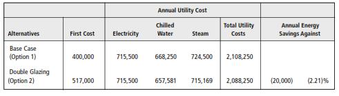
One way to evaluate the cost-effectiveness of LCCA alternatives is to look at their “payback” against the base case. The payback term is the time it takes an option to have the same life cycle cost as the base case. Fig. 6 shows the cumulative cost of the LCCA alternative compared to a base case. The point at which each alternative line crosses the base-case line is the payback point.
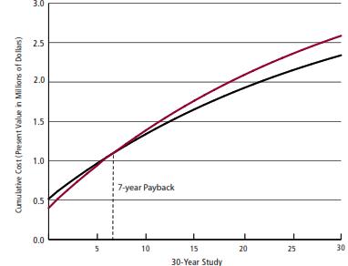
The LCCA showed that despite the $117,000 increase in first costs for the improved glazing, the avoided cost of approximately $20,000 per year in steam and chilled-water costs resulted in a payback of less than seven years. As a result, the alternative, Glazing Option 2, was selected.
Figure11.6ClarkCenterGlazingOptions
Sustainable Building Design 182
Sustainable Building Design 183
12 Sustainabilityasaprocessforurban development
D-r Ognen Marina
Today, cities are everywhere. From the first sedentary settlements to the contemporary territorial and digital extensions cities have become global phenomena. According to The World Bank urban development report52 over a half of the world population already lives in the urban environments with the prospect that more than 80% of the world population will become urban until year 2020 Cities are at once an expression of the cultural practices and technologies of the present53 During this process of urbanization human civilization has become heavily depended on dynamics and the complexity of urban environments. The density of the population in the urban areas pose a constant challenge on urban and spatial planning, energy, transportation, water, public buildings and area, provisions of services, as well as on the climate change and the urban resilience. So, solutions for these pressures should be both highly efficient and sustainable on one hand, and on the other hand should generate development and socialwellbeing with increased resilience.
Cities are complex and cities are dynamic. Cities have always been a mixing place between people and social, structural, cultural, legal, governmental, technological and other systems. The complexity of the cities and the emerging interactions make cities interesting and important for people. The variety of possibilities emerging through endless iterations of diverse systems and people are creating a unique environment for development and innovations. The density of people, ideas, interests and variety of social and spatial practices also create a critical territory of everyday conflicts that must be resolve, hence cities also face immanent pressure for adaptation and change. This process of constant adaptation and change is fertile ground for urban, social and technological development. This leads to reinvention of cities, where sustainability and the new requirements mandate smarter and resilient solutions and operations in cities.
However, the big questions that pertains is what actually sustainability means for cities and for urban development in general? Although its official definition from the
Sustainable Building Design 184
52 TheWorldBank,2014 53 Verebes,2014
1992 Brundtland Report54is unambiguous, but, what does it mean and how should cities approach it? The realm of participants showed a variety of understandings. For many researchers and practitioners, it is for society to become more resilient, which in turn would make our ecosystems more resilient. From a people-based approach, to a planning-based one, focusing on regeneration or the inclusion of environment in local policies can only bring in consensus and a chance for all stakeholders to adjust their visions and priorities55
12.1. Thechallengeofsustainabilityincities
At the end of the 20th Century and beginning of 21st Century two emergent phenomena, urbanization and technologies shaped the societies through technological advancement and economic growth while increasing the quality of living especially in urban centers. This fostered the progressive development of urban areas at the expenses of the rural areas with manifold increase of the urban population. Such enormous congregation and concentration of people inevitably led to both positive and negative effects at local and global level. On one side it created new job opportunities, improvement of economic conditions and creative multicultural environment, but on the other side it also created the enormous pollution of the environment, traffic congestion, carbon dioxide and other greenhouse gases emission, enormous energy consumption, waste and deterioration of quality of living conditions. Another set of problems are more social and associated with lack of comprehensive vision for cities, competing interest and objectives, multiple stakeholders, lack of civic participation in decision making, social and political confrontation and complexity. Ensuring the positive effects of the urbanization and new technologies with high quality of living conditions in cities requires a deeper understanding of the synergies and interdependence between processes that are shaping contemporary societies. These challenges are triggering many cities around the world to find smarter ways to manage them.
The latest considerations brought afore by Saskia Sassen reflecting on the urban sustainability concept brings a fresh look on the idea of sustainability. Sassen suggest that historically, the city is formed through its complexity and its incompleteness, its unfinished nature, always developing and expanding, with no clear limits. According to her, setting up enclosed technical systems in a city to govern all its main functions can only weaken this vitalmix56 . 54
Sustainable Building Design 185
"Sustainabledevelopmentisdevelopmentwhichmeetstheneedsofthepresentwithoutcompromisingtheability offuturegenerationtomeettheirownneeds." WorldCommissiononEnvironmentandDevelopment,‘OurCommon Future’. 55 URBACT-Bringingmoresustainabilitytocities:5golednrules 56 Sassen,2014.
12.2.
Strategiesforachievingsustainabilityincities
The 2030 Agenda for Sustainable Development, adopted by all United Nations Member States in 2015, provides a blueprint for achieving the desired sustainability through establishment of 17 Sustainable Development Goals (SDGs), which are an urgent call for action. They recognize that ending poverty and other deprivations must go hand-in-hand with strategies that improve health and education, reduce inequality, and spur economic growth – allwhile tackling climate change and working to preserve our oceans and forests57 .
The multitude of the definitions and goals of the sustainability concept suggest that the idea of the sustainability is still open for exploration and that it is still a subject of improvement through practical, real-life implementations that provide a valuable knowledge and experience for enhanced view of the smart cities. In the context of the urban development it is also providing a wide opportunity for local and context sensitive interpretations that should respond better to the specifics of the diversity of the urban aspects that comprise the complexity of contemporary cities and integrating them into a sustainable organicand functional whole.
The importance of the integration of city’s various systems, transport, energy, education, health care, built environment, physical infrastructure, food, water, public safety and others in creation of Smart Cities has been emphasized through acknowledgement that these systems does not operate within the frame of the cities as a separate entity but rather as mutually interdependent complex network of interrelations and influences creating the overarching multitude of the urban reality. This fact that infusing technology or intelligence into each of the subsystems of the city in a separate manner does not improve the efficiency and functionality of the system nor does it provide enhanced potential within the urban complexity. However, the inherent complexity of the urban systems and subsystems especially when observed as a whole does not permit a comprehensive understanding of the specifics of the systems in the scope of the Sustainability concept application. With the intention of the better understanding what constitutes the sustainability many authors have proposed several dimensions and characteristics of the concept providing an integrated framework for observation of the Sustainability concept through development of sustainable strategies
Development sustainable strategies are focused on several principles or dimensions of sustainable development. The Sustainable development strategies’ focus is on five dimensions: economic sustainability, social sustainability, ecological sustainability, sustainable spatial development, and cultural continuity. The main dimensions of the sustainability and accordingly the sustainable urban development can be defined through following actions: Economic stability which can be defined as outcome of better allocation and efficient management of resources and continuous flow of private and governmental investment; Social sustainability which means: creating development process, that its
Sustainable Building Design 186
57 TransformingourWorld:the2030AgendaforSustainableDevelopment, UNHABITAT,2015
continuance is depended on another growth; Ecological sustainability, through limiting the consumption of sources which are exhaustible; reducing the waste, pollution and recycling the sources; The sustainable spatial development, whose aim is to achieve a more balanced rural- urban institution and a better distribution ofland; The cultural continuity which includes finding endogenous roots of renewal patterns, and farming systems and the processes that can create some changes in the cultural continuity.
Thus, sustainable urban development is one of the fundamental pillars of sustainable development, and the process of sustainable urban development can be discussed in this context. The target of sustainable urban development process is to achieve the status of "sustainability" in urban communities and also to create or to strengthen the sustainability’s characteristics ofeconomic, social, culturaland environmentalcity.
12.3.Achievingsustainabilitythroughproject
Among the methodological and practical approaches that enables all the stakeholder to shape the sustainable urban development through a process that is inclusive, comprehensive and goal oriented is Symbiocity approach. This approach is a holistic and inclusive approach to sustainable urban development based on Swedish municipal experiences. SKL International and the Swedish Association of Local Authorities and Regions (SALAR) use SymbioCity to help local, regional and national administrations around the world to plan and build sustainable and inclusive cities.
By focusing on the opportunities that urbanization offers, SymbioCity contributes to achieving Goal 11 – Sustainable cities and communities: Make cities and human settlements inclusive, safe, resilient & sustainable. However, the complexity of the cities determines that Goal 11 cannot be viewed in isolation and in reality, the only possibility for innovation and creation of innovative and sustainable solutions is only through observation of the existing challenges within the broader and more inclusive context The Symbiocity approach is structured around the proactive idea of creation of a vision of the future urban development rather than a reactive approach to the existing problems58. This change in the approach enables all the stakeholders in the process to focus on the opportunities rather than to the obstacles. It provides an inclusive approach to sustainable urban development in most of its main dimensions: environmental, sociocultural, economic and spatial. It seeks to provide synergies in the three main dimensions of the urban life: environmental, socio-cultural and economic. In order to improve living standards, safety, comfort and quality of life it is based on comprehensive assessment of urban systems, tackling institutional factors and a profound and proactive actions in the spatial dimension of the society and cities. It is foreseen to be an approach that should enable sustainability in urban development by including stakeholders and citizens in the urban development process. 58 Throughvariousworkingmethods,SymbioCityenablescitiestomakesustainabilityassessmentsoftheirurban environmentsanddevelopsolutionsthataretailoredtolocalconditions.
Sustainable Building Design 187
In the recent update this holistic and inclusive approach to sustainable urban development lays the foundation for the practical model in five key principles: From silos to multidisciplinary teams; From problem-based to vision-based; From single effects to synergies; From top-down to bottom-up processes; and From reactive to proactive. The approach has been shaped as a six-step working process with associated entry points and tools forms the practicalmethodology59
Planningtheprocess
For a successful process of sustainable urban planning it is most important to have a clear vision of the process, stakeholders that will be involved and the time plan of actions. An organizational plan must define activities, their relationships and the involvement of all relevant stakeholders. At this initial stage, it is necessary to identify possible stakeholders for the review phase and define an organizational structure, including the representatives from different fields, tiers of government and other community stakeholders. The project organizational structure should also reflect the specific conditions and a comprehensive structure of project steering group, multidisciplinary planning or review team, and involvement from local and regionallevelare allpotentially useful.
Understandingthecontext


In order to be able to understand the context and the sources of the current challenges it is necessary to map the local conditions, to identify needs, problems challenges and opportunities. Through analysis of existing urban strategic plans, policies, statistics and other relevant data it is foreseen to gain oversight of primary challenges and potential opportunities in the city and to make the diagnosis of the current conditions. It is important to look at how issues interrelate and connect to different sources and causes and also start to delimit and concentrate on specific areas. Communication with stakeholders – ranging from ordinary citizens to businesses – is crucialin this phase.
Creatingthevision-measuringtheprocess
The aim of this step is to enable creation of the vision for the future urban development. In order to make this important step it is necessary to articulate the establishment of goals and objectives of the project based on the assessment and analysis of the results of the previous step. It is expected to specify objectives, targets and indicators using the set of methods through inclusive and participative process of discussion with key stakeholders. The main overall objectives should reflect the basic ambition of improving sustainability over the short,
Sustainable Building Design 188
59 ImplementingtheAgenda2030throughSymbioCity
mid and long term. For the purpose of measuring the development of the process and the levelof success targets and indicators must be formulated based on measurable objectives
Alternativescenarios
Creating a solution through a linear process of analysis, research and decision making could lead us to a viable solution to one of the problems but in the same time creation ofa series of new challenges jeopardizing the idea of the sustainable solutions. Therefore, it is necessary to embrace the processes an iterative and circular activity of understanding the problems and creation of solutions through constant challenging the decisions. Hence, it is essentialin order to be able to respond to multiple challenges to develop alternative proposals through use of findings from the first three steps to identify and formulate a range of alternative development proposals for the city development You can perform this iterative analysis of solutions and create alternative scenarios through back casting exercise and devise scenarios for your city highlighting different options for urban infrastructure and systems development. The idea is to find different ways to reach your targets and identify potential opportunities and limitations so you can make the right choices going forward.
Potentialimpact


Creating solutions through comprehensive analysis of socio-cultural, economic and environmental factors could lead to complex scenarios with multiple influences on various domains of the society. Hence, studying and evaluating the economic, social, environmental and spatial impacts of alternative proposals and solutions is a critical step towards finding the right way forward for the city. The impact of the designed solutions must be evaluated as a basis for If any of the proposed solutions suggest a harmful impact to any of the domains of the society and the environment or community it is of utmost necessity to resort to alternative scenarios or to investigate the positions developed in the previous steps in an iterative process.
Strategyforprojectimplementation
The final proposal might be structured as a single scenario or synergy of multiple measures and actions. Synergies between different systems are vital for optimization of the effects and sustainable urban development. The decision to choose the right and suitable implementation strategy might lead you to a successful transformation or to the utter failure to the otherwise good measures and actions. These measures must take account of the full range of sustainability challenges in the local context and also mesh with existing plans and strategies. From here, you’re ready to decide on a suitable implementation strategy for a sustainable urban development.
Sustainable Building Design 189
12.4.Conclusion
The process of sustainable urban development must address all the dimensions of the contemporary societies with the people in its very core. The synergies of the existing dimensions of the cities and the urban environment must enable the creation of a comprehensive and viable approach to the pending problems through creation of integrated and sustainable solutions. This process for achieving sustainability must provide both a theoretical approach and a practical methodology stated in the New Urban Agenda and the Global Development Goals in order to address the urban challenges defined and depicted by the institutions, researchers and citizens in a comprehensive and complex way.
Sustainable Building Design 190
Bibliography
[1] W. Bakens, ‘Realizing the sector’s potencial for contributing to sustainable development’, UNEP Industry and Environment, no. Април-Септември, pp. 9–12, 2003.
[2] V. Masson-Delmotte et al., ‘IPCC, 2021: Climate Change 2021: The Physical Science Basis. Contribution of Working Group I to the Sixth Assessment Report of the Intergovernmental Panel on Climate Change’, Cambridge University Press. In Press.
[3] ‘Global Assessment Report on Biodiversity and Ecosystem Services’, United Nations’ Intergovernmental Science-Policy Platform on Biodiversity and, May 2019. Accessed: Aug. 09, 2021. [Online]. Available: http://ipbes.net/global-assessment
[4] U. N. E. Programme and G. A. for B. and Construction, ‘2020 Global Status Report for Buildings and Construction: Towards a Zero-emissions, Efficient and Resilient Buildings and Construction SectorExecutive Summary’, 2020, Accessed: Aug. 09, 2021. [Online]. Available: https://wedocs.unep.org/xmlui/handle/20.500.11822/34572
[5] J. Elkington, Cannibals with Forks: Triple Bottom Line of 21st Century Business. Oxford: Capstone Publishing Ltd, 1999.
[6] World Commission on Environment and Development, ‘Our common future’, Oxford: Oxford University Press, 1987.
[7] J. Friedrich, M. Ge, and A. Pickens, ‘This Interactive Chart Shows Changes in the World’s Top 10 Emitters’, Oct. 2020, Accessed: Jul. 25, 2021. [Online]. Available: https://www.wri.org/insights/interactive-chart-shows-changes-worlds-top-10-emitters
[8] UN, ‘Net Zero Coalition’, United Nations, 2021. https://www.un.org/en/climatechange/net-zerocoalition (accessed Jul. 25, 2021).
[9] ‘Secretary-General’s statement on the IPCC Working Group 1 Report on the Physical Science Basis of the Sixth Assessment | United Nations Secretary-General’, 2021. https://www.un.org/sg/en/content/secretary-generals-statement-the-ipcc-working-group-1report-the-physical-science-basis-of-the-sixth-assessment (accessed Aug. 09, 2021).
[10] J. Rogejl, D. Shindell, S. Jiang, and V. Forster, ‘Chapter 2: Mitigation Pathways Compatible with 1.5°C in the Context of Sustainable Development. In: Global Warming of 1.5°C. An IPCC Special Report on the impacts of global warming of 1.5°C above pre-industrial levels and related global greenhouse gas emission pathways, in the context of strengthening the global response to the threat of climate change, sustainable development, and efforts to eradicate poverty’, 2018. Accessed: Jul. 25, 2021. [Online]. Available: https://www.ipcc.ch/report/sr15/mitigation-pathways-compatiblewith-1-5c-in-the-context-of-sustainable-4-development/
[11] ‘WorldResources Institute’, 2019. https://www.wri.org/ (accessed Jul.25, 2021).
[12] ‘Proposal for a Directive on energy efficiency (recast)’, European Commission - European Commission, 2021. https://ec.europa.eu/info/files/proposal-directive-energy-efficiencyrecast_en (accessed Jul. 29, 2021).
[13] ‘Energy consumption in households’, 2019. https://ec.europa.eu/eurostat/statisticsexplained/index.php?title=Energy_consumption_in_households (accessed Oct. 13, 2021).
[14] M. Santamouris, ‘Cooling the buildings – past, present and future’, Energy and Buildings, vol. 128, pp. 617–638, Sep. 2016, doi: 10.1016/j.enbuild.2016.07.034.
Sustainable Building Design 191
[15] N. E. Klepeis et al., ‘The National Human Activity Pattern Survey (NHAPS): a resource for assessing exposure to environmental pollutants’, J Expo Anal Environ Epidemiol, vol. 11, no. 3, pp. 231–252, Jul. 2001, doi: 10.1038/sj.jea.7500165.
[16] W. J. Fisk, ‘Health and Productivity Gains from Better Indoor Environments and Their Relationship with Building Energy Efficiency’, Annual Review of Energy and the Environment, vol. 25, no. 1, pp. 537–566, 2000, doi: 10.1146/annurev.energy.25.1.537.
[17] Derek Clements-Croome, Creating the Productive Workplace. Routledge, 2006. Accessed: Aug. 07, 2014. [Online]. Available: http://www.tandfebooks.com/doi/abs/10.4324/9780203696880
[18] N. Miller and D. Pogue, ‘Do Green Buildings Make Dollars and Sense?’, Burnham-Moores Center for Real Estate University of San Diego, CB Richard Ellis, 2009.
[19] U.S. Green Building Council, ‘Building momentum: National trends and prospects for highperformance green buildings’, Washington, D.C., Prepared for the U.S. Senate Committee on Environment and Public Works, 2003.
[20] Heschong Mahone Group and L. Heschong, ‘Daylighting and Human Performance’, Lawrence Berkeley National Laboratory, 2002.
[21] C. I. Seresinhe, T. Preis, and H. S. Moat, ‘Quantifying the Impact of Scenic Environments on Health’, Scientific Reports, vol. 5, 2015, doi: 10.1038/srep16899.
[22] C. Guy-Quint, ‘Tackle Climate Change:Use Wood’, European Parliament Brussels,2006.
[23] McGraw-Hill Construction, ‘Green building smart market report: Design & construction intelligence’, New York, 2006.
[24] T. Runde and S. Thoyre, ‘Integrating Sustainability and Green Building into the Appraisal Process’, Journal of Sustainable Real Estate, vol. 2, no. 1, pp. 221–248, 2010, doi: 10.5555/jsre.2.1.82414503l8476wk0.
[25] M. Brown et al., Eds., Sustainability, Restorative to Regenerative. Vienna: RESTORE Working Group One Report: Restorative Sustainability, 2018. [Online]. Available: https://www.eurestore.eu/wpcontent/uploads/2018/04/Sustainability-Restorative-to-Regenerative.pdf
[26] E. Naboni and L. Havinga, Regenerative Design in Digital Practice: A Handbook for the Built Environment. Bolzano, IT: Eurac, 2019.
[27] ‘Climate Emergency Design Guide’, LETI, 2020. https://www.leti.london/cedg (accessed Aug. 10, 2021).
[28] ‘Circular economy introduction - Overview’, Ellen Macarthur Foundation, 2021. https://ellenmacarthurfoundation.org/topics/circular-economy-introduction/overview (accessed Sep. 28, 2021).
[29] ‘Net Zero Carbon Buildings: A Framework Definition’, UKGBC - UK Green Building Council, 2019. https://www.ukgbc.org/ukgbc-work/net-zero-carbon-buildings-a-framework-definition/ (accessed Aug. 10, 2021).
[30] ‘Embodied Carbon Primer’, LETI, 2020. https://www.leti.london/ecp (accessed Sep. 14, 2021).
[31] ‘Declare - International Living Future Institute’, 2021. https://declare.living-future.org/ (accessed Oct. 07, 2021).
[32] ‘2030 Climate Challenge’, 2019. https://www.architecture.com/about/policy/climate-action/2030climate-challenge (accessed Aug. 05, 2021).
[33] ‘MVRDV Reveals Design of Green Barcode-Inspired Housing Unit in Amsterdam | ArchDaily’. https://www.archdaily.com/963399/mvrdv-reveals-design-of-green-barcode-inspired-housingunit-in-amsterdam?ad_source=search&ad_medium=search_result_all (accessed Oct. 05, 2021).
[34] ‘UN17 Village to be built in Copenhagen with recycled materials’, Dezeen, Dec. 10, 2018. https://www.dezeen.com/2018/12/10/un17-village-eco-housing-copenhagen-lendager-grouparstiderne-arkitekter/ (accessed Oct. 05, 2021).
[35] ‘MiranKambicPhotography’, 2019. http://www.mirankambic.com/f3-housing-brdo.html (accessed Oct. 14, 2021).
[36] ‘Energy Community Homepage’, 2019. https://energy-community.org/ (accessed Oct. 14, 2021).
[37] ‘Lacaton-Vassal’, Lacaton-Vassal, 2019. www.lacatonvassal.com (accessed Oct. 05, 2021).
[38] N. Lechner, Heating, cooling, lighting: design methods for architects, 3rd ed. Hoboken, N.J.: Wiley, 1991.
Sustainable Building Design 192
[39] R. L. Knowles, ‘The solar envelope: its meaning for energy and buildings’, Energy and Buildings, vol. 35, no. 1, pp. 15–25, Jan. 2003, doi: 10.1016/S0378-7788(02)00076-2.
[40] A. Vartholomaios, ‘The residential solar block envelope: A method for enabling the development of compact urban blocks with high passive solar potential’, Energy and Buildings, vol. 99, pp. 303–312, Jul. 2015, doi: 10.1016/j.enbuild.2015.04.046.
[41] F. D. Luca, ‘From Envelope to Layout - Buildings Massing and Layout Generation for Solar Access in Urban Environments’, undefined, 2017, Accessed: Oct. 08, 2021. [Online]. Available: https://www.semanticscholar.org/paper/From-Envelope-to-Layout-Buildings-Massing-and-forLuca/dc5a9afaa70584a1039c1997a8788df40c63d6bf
[42] F. D. Luca, ‘Solar Form-finding. Subtractive Solar Envelope and Integrated Solar Collection Computational Method for High-rise Buildings in Urban Environments’, De Luca, F., DISCIPLINES & DISRUPTION. 37th Annual Conference of the Association for Computer Aided Design in Architecture - ACADIA 2017, Massachusetts Institute of Technology, Cambridge (MA), 2-4 November, pp. 212-221, Accessed: Oct. 08, 2021. [Online]. Available: https://www.academia.edu/34264708/Solar_Form_finding_Subtractive_Solar_Envelope_and_In tegrated_Solar_Collection_Computational_Method_for_High_rise_Buildings_in_Urban_Environ ments
[43] D. Mumovic and M. Santamouris, A Handbook of Sustainable Building Design and Engineering: An Integrated Approach to Energy, Health and Operational Performance, First edition. London ; Sterling, VA: Routledge, 2009.
[44] ‘Passive Design Toolkits | BC Climate Action Toolkit’, 2009. https://toolkit.bc.ca/resource/passivedesign-toolkit (accessed Oct. 19, 2021).
[45] V. Olgyay, D. Lyndon, J. Reynolds, and K. Yeang, Design with Climate: Bioclimatic Approach to Architectural Regionalism - New and expanded Edition, Revised edition. Princeton: Princeton University Press, 2015.
[46] A. Petrovski, T. Samardzioska, and A. Trombeva-Gavrilovska, ‘Analysis of insolation in regard to the orientation of surfaces’, in 5th International Conference, Zabljak, Montenegro, Feb. 2014, pp. 1665–1671.
[47] G. Roberto and R. Vallentin, Passive House Design: Planning and design of energy-efficient buildings. München: DETAIL, 2014.
[48] A. Salvati, H. Coch, and M. Morganti, ‘Effects of urban compactness on the building energy performance in Mediterranean climate’, Energy Procedia, vol. 122, pp. 499–504, Sep. 2017, doi: 10.1016/j.egypro.2017.07.303.
[49] M. Kottek, J. Grieser, C. Beck, B. Rudolf, and F. Rubel, ‘World Map of the Köppen-Geiger climate classification updated’, Meteorologische Zeitschrift, pp. 259–263, Jul. 2006, doi: 10.1127/09412948/2006/0130.
[50] ‘The Passive House’, 2020. https://passipedia.org/basics/the_passive_house_-_definition (accessed Aug. 10, 2021).
[51] V. Cheng, E. Ng, and B. Givoni, ‘Effect of envelope colour and thermal mass on indoor temperatures in hot humid climate’, Solar Energy, vol. 78, no. 4, pp. 528–534, Apr. 2005, doi: 10.1016/j.solener.2004.05.005.
[52] Edward Mazria, The Passive Solar Energy Book: A Complete Guide to Passive Solar Home, Greenhouse and Building Design. Rodale Pr; First Edition edition, 1979.
[53] A. Wood and R. Salib, Eds., Guide To Natural Ventilation in High Rise Office Buildings, 1st edition.New York: Routledge, 2012.
[54] J. Martí-Herrero and M. Heras-Celemin, ‘Dynamic physical model for a solar chimney’, Solar Energy, Jan. 2007, doi: 10.1016/j.solener.2006.09.003.
[55] Y. Wu, N. Gao, J. Niu, J. Zang, and Q. Cao, ‘Numerical study on natural ventilation of the wind tower: Effects of combining with different window configurations in a low-rise house’, Building and Environment, vol. 188, p. 107450, Jan. 2021, doi: 10.1016/j.buildenv.2020.107450.
[56] A. A. Saleem, M. Bady, S. Ookawara, and A. K. Abdel-Rahman, ‘Achieving standard natural ventilation rate of dwellings in a hot-arid climate using solar chimney’, Energy and Buildings, vol. 133, pp. 360–370, Dec. 2016, doi: 10.1016/j.enbuild.2016.10.001.
Sustainable Building Design 193
[57] D. O’Connor, J. K. S. Calautit, and B. R. Hughes, ‘A review of heat recovery technology for passive ventilation applications’, Renewable and Sustainable Energy Reviews, vol. 54, pp. 1481–1493, Feb. 2016, doi: 10.1016/j.rser.2015.10.039.
[58] T. S. Bisoniya, ‘Design of earth–air heat exchanger system’, Geothermal Energy, vol. 3, no. 1, p. 18, Sep. 2015, doi: 10.1186/s40517-015-0036-2.
[59] Y. Yu, H. Li, F. Niu, and D. Yu, ‘Investigation of a coupled geothermal cooling system with earth tube and solar chimney’, Applied Energy, vol. 114, pp. 209–217, Feb. 2014, doi: 10.1016/j.apenergy.2013.09.038.
[60] J. Schnieders et al., ‘Design and realisation of the Passive House concept in different climate zones’, Energy Efficiency, vol. 13, no. 8, pp. 1561–1604, Dec. 2020, doi: 10.1007/s12053-019-09819-6.
[61] A. Soto, P. J. Martínez, P. Martínez, and J. A. Tudela, ‘Simulation and experimental study of residential building with north side wind tower assisted by solar chimneys’, Journal of Building Engineering, vol. 43, p. 102562, Nov. 2021, doi: 10.1016/j.jobe.2021.102562.
[62] H. Campaniço, P. M. M. Soares, P. Hollmuller, and R. M. Cardoso, ‘Climatic cooling potential and building cooling demand savings: High resolution spatiotemporal analysis of direct ventilation and evaporative cooling for the Iberian Peninsula’, Renewable Energy, vol. 85, pp. 766–776, Jan. 2016, doi: 10.1016/j.renene.2015.07.038.
[63] A. Krstić-Furundžić, M. Vujošević, and A. Petrovski, ‘Design scenarios of the office building facade with regard to energy and environmental performance’, in The Proceedings of the 13th Conference on Sustainable Development of Energy, Water and Environment Systems - SDEWES 2018, Palermo, Italy, Oct. 2018, vol. Special session of invited papers: RENEWABLE ENERGIES, INNOVATIVE HVAC SYSTEMS AND ENVELOPE TECHNOLOGIES FOR THE ENERGY EFFICIENCY OF BUILDINGS.
[64] ‘Shading’, Fairconditioning, 2019. http://fairconditioning.org/knowledge/passive-design/shading/ (accessed Oct. 21, 2021).
[65] A. Petrovski, A. Kochov, and V. Zileska - Pancovska, ‘Sustainable improvement of the energy efficiency of an existing building’, Mechanical Engineering - Scientific Journal, vol. 32, no. 1, pp. 45–49, 2014.
[66] S. M. Porritt, P. C. Cropper, L. Shao, and C. I. Goodier, ‘Ranking of interventions to reduce dwelling overheating during heat waves’, Energy and Buildings, vol. 55, pp. 16–27, Dec. 2012, doi: 10.1016/j.enbuild.2012.01.043.
[67] ‘Passive House Bruck / Peter Ruge Architekten’, ArchDaily, 2014. https://www.archdaily.com/569638/passive-house-bruck-peter-ruge-architekten-2 (accessed Oct. 26, 2021).
[68] ‘North Vancouver Passive House Plus by MGA - Michael Green Architecture’, AmazingArchitecture, 2021. https://amazingarchitecture.com/houses/north-vancouver-passive-house-plus-by-mgamichael-green-architecture (accessed Oct. 26, 2021).
[69] ‘NanaWall’, NanaWall, 2019. https://www.nanawall.com/blog/energy-efficient-building-designlessons-in-passive-building-design-from-the-omena-house (accessed Oct. 26, 2021).
[70] ‘Casa Studio Passive House | Piraccini + Potente Architettura’, Archello, 2018. https://archello.com/fr/project/casa-studio-passive-house (accessed Oct. 26, 2021).
[71] ‘rhb architectes · Passive house’, Divisare, 2020. https://divisare.com/projects/312174-rhbarchitectes-passive-house (accessed Oct. 26, 2021).
[72] ‘Feldman architecture’, Dezeen, Dec. 10, 2018. https://feldmanarchitecture.com/project/caterpillarhouse/ (accessed Oct. 05, 2021).
[73] G. Pérez, J. Coma, I. Martorell, and L. F. Cabeza, ‘Vertical Greenery Systems (VGS) for energy saving in buildings: A review’, Renewable and Sustainable Energy Reviews, vol. 39, pp. 139–165, Nov. 2014, doi: 10.1016/j.rser.2014.07.055.
[74] Y. Stav and G. Lawson, ‘Vertical vegetation design decisions and their impact on energy consumption in subtropical cities’, Ancona, Italy, May 2012, pp. 489–500. doi: 10.2495/SC120411.
[75] T. A. M. Pugh, A. R. MacKenzie, J. D. Whyatt, and C. N. Hewitt, ‘Effectiveness of Green Infrastructure for Improvement of Air Quality in Urban Street Canyons’, Environ. Sci. Technol., vol. 46, no. 14, pp. 7692–7699, Jul. 2012, doi: 10.1021/es300826w.
[76] P. Blanc, V. Lalot, and J. Nouvel, The Vertical Garden: From Nature to the City. New York: W. W. Norton & Company, 2008.
Sustainable Building Design 194
[77] M. Davies, ‘A wall for all seasons’, RIBA Journal, vol. 88, no. 2, pp. 55–57, 1981.
[78] R. Loonen, M. Trčka, D. Cóstola, and J. L. M. Hensen, ‘Climate adaptive building shells: state-of-theart and future challenges’, Renewable and Sustainable Energy Reviews, vol. 25, pp. 483–493, 2013.
[79] M. V. Nielsen, S. Svendsen, and L. B. Jensen, ‘Quantifying the potential of automated dynamic solar shading in office buildings through integrated simulations of energy and daylight’, Sol. Energy, vol. 85, no. 5, pp. 757–768, May 2011, doi: 10.1016/j.solener.2011.01.010.
[80] D. M. Addington and D. Schodek, Smart Materials and Technologies: For the Architecture and Design Professions, 1 edition. Amsterdam; Boston: Routledge, 2004.
[81] A. Petrovski, V. Zileska - Pancovska, and V. Zujo, ‘Improving building sustainability by optimizing facade shape and solar insolation use’, in International Scientific Conference People, Buildings and Environment 2014 (PBE2014), Kromeriz, Czech Republic, Oct. 2014, pp. 374–383.
[82] ‘ISO 14040:2006(en), Environmental management Life cycle assessment Principles and framework’. https://www.iso.org/obp/ui/#iso:std:iso:14040:ed-2:v1:en (accessed Sep. 18, 2021).
[83] ‘mdc.Architectonica’, 2018. http://www.arh.com.mk/page.php?page=0 (accessed Jun. 09, 2018).
[84] J. Ivanović-Šekularac, J. Čikić-Tovarović, and N. Šekularac, ‘Restoration and conversion to re-use of historic buildings incorporating increased energy efficiency: A Case Study – the Haybarn Complex, Hilandar Monastery, Mount Athos’, Thermal Science, vol. 20, no. 4, pp. 1363–1376, 2016, doi: 10.2298/TSCI160208131I.
[85] C. A. S. Hill, Wood Modification: Chemical, Thermal and Other Processes. John Wiley & Sons,2006.
[86] D. Sandberg, A. Kutnar, and G. Mantanis, ‘Wood modification technologies - a review’, iForestBiogeosciences and Forestry, vol. 10, no. 6, pp. 895–908, 2017, doi: 10.3832/ifor2380-010.
[87] ‘Living Building Challenge 3.1’, 2018. http://living-future.org/lbc (accessed Dec. 29, 2018).
Sustainable
Design 195
Building
The project is co-financed by the Governments of Czechia, Hungary, Poland and Slovakia through Visegrad Grants from International Visegrad Fund. The mission of the fund is to advance ideas for sustain able regional cooperation in Central Europe.