BEAT THE HEAT
ENGINEERING EXTRA
|
In-Depth Technology for Radio Engineers
The author is assistant director of information technology of educational broadcast services at Texas A&M University; and the director of engineering for KAMU Public Radio and Television. He was the 2014 recipient of the Radio World Excellence in Engineering Award. This paper appears in the “Proceedings of the 2018 NAB Broadcast Engineering and Information Technology Conference” and is reprinted with permission of the National Association of Broadcasters. The broadcast technical plant today looks more like a data center. It is a data center as the industry migrates to an Information Technology (IT) infrastructure. It is essential for the broadcast
• Dead Air • Undesirable Program Content • Unavailable Resources • Loss of Revenue • Public Embarrassment •P otential Liability Broadcast engineers focus upon minimizing dead air or the loss of program content broadcast. Many of the security incidents that have occurred that are oriented towards the broadcast facility target the disruption of the program con-
D
C
engineer to understand network security, have the tools, and have the knowledge to implement a secure network environment within his or her broadcast facility. Security risks to the broadcast facility can be far-ranging and includes undesired conditions (see reference [1] at the end of this article) such as:
Contact Us Today to Learn More 1-800-237-1776 | www.comrex.com
IP Network Security Availability Denial
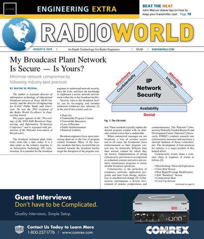
Fig. 1: The CIA triad.
tent. These incidents typically replace the desired program content with an alternate content source that is undesirable. When commercial messages are not broadcast, a loss of revenue occurs and in all cases, the broadcaster faces embarrassment as their program content may be drastically different than their normal content for which they are known. Implementation of strong cybersecurity provisions is as important as redundant systems and active preventative maintenance programs to insure reliable broadcast operations. Cybersecurity is the protection of computers, networks, application programs and data from change, destruction or unauthorized change [2]. Cybersecurity encompasses a diverse environment of attacks, compromises and
Guest Interviews with no bleed Don’t haveAd to be Complicated. Quality Interviews, Simple Setup.
RADIOWORLD.COM
n tio ra ty te gri e
BY WAYNE M. PECENA
|
t In
Minimize network compromise by following industry best practices
$5.00
Al
My Broadcast Plant Network Is Secure — Is Yours?
|
on isc fid los en ur tia e lty
AUGUST 8, 2018
John Marcon shares tips on how to keep your transmitter cool. Page 18
countermeasures. The National Cybersecurity Federally Funded Research and Development Center (National Cybersecurity FFRDC) conducts research into cybersecurity measures and maintains a national database of threat vulnerabilities. The development of best practices for industry is a major product of this federal effort. Cybersecurity events share a common chain or sequence of events as follows [2]: • Host Probing / Network Exploration • Gain Host Access • Host Right/Privilege Modification • Add “Backdoor” Access •C ompromise Host • Cover Up Actions
- 9.25” x 2.25”
(continued on page 6)
W H E AT N E T- I P INTELLIGENT NETWORK
The Future Can Bring Anything
2040
ANOTHER ODYSSEY
LXE is Ready for Everything Virtually every button, knob, and display on the LXE is programmable using ConsoleBuilder. And you can design dynamic custom touchscreen interfaces to augment LXE’s extensive screen set with ScreenBuilder.™ Need more input faders? Enable up to four layers to multiply the number (up to 32) in the same footprint. Whether it’s 2020, 2040, or 2080, your LXE will adapt to your needs.
Your Forever Console Download your free E-Book: Advancing AoIP for Broadcast
wheatstone.com/wnip-rw BROADCAST AUDIO PERFECTIONISTS®
phone 1.252.638-7000 | wheatstone.com | sales@wheatstone.com
ENGINEERING EXTRA Vol. 42 No. 20
August 8, 2018
www.radioworld.com FOLLOW US www.twitter.com/radioworld_news www.facebook.com/RadioWorldMagazine CONTENT Managing Director, Content Paul J. McLane paul.mclane@futurenet.com, 703-852-4628 Senior Content Producer — Technology Brett Moss, brett.moss@futurenet.com Content Manager Emily M. Reigart, emily.reigart@futurenet.com Technical Advisors Thomas R. McGinley, Doug Irwin Technical Editor, RWEE W.C. “Cris” Alexander, rweetech@gmail.com Content Director — International Marguerite Clark Contributors: Susan Ashworth, Dave Beasing, John Bisset, James Careless, Ken Deutsch, Mark Durenberger, Charles Fitch, Travis Gilmour, Donna Halper, Craig Johnston, Alan Jurison, Paul Kaminski, John Kean, Peter King, Larry Langford, Mark Lapidus, Jim Peck, Mark Persons, Stephen M. Poole, James O’Neal, Rich Rarey, Jeremy Ruck, John Schneider, Randy Stine, Jennifer Waits, Tom Vernon Production Manager Caroline Freeland Managing Design Director Nicole Cobban Senior Design Director Karen Lee ADVERTISING SALES VP/Media Technology Group Carmel King, carmel.king@futurenet.com, 703-852-4602 Publisher, Radio World International Raffaella Calabrese, raffaella.calabrese@futurenet.com, +39-320-891-1938 SUBSCRIBER CUSTOMER SERVICE To subscribe, change your address, or check on your current account status, go to www.radioworld.com and click on About Us, email futureplc@computerfulfillment.com, call 888-266-5828, or write P.O. Box 282, Lowell, MA 01853. ARCHIVES This magazine is available for research and retrieval of select archived articles from leading electronic database and search services, including ProQuest. For microform availability, contact National Archive Publishing Company, 800-521-0600, or search the Serials in Microform listings at napubco.com. Back issues are available. For more information, contact www.proquest.com. REPRINTS/PERMISSIONS This magazine may not be reproduced or quoted in whole or in part by printed or electronic means without written permission from Future. To obtain permissions, contact Wright’s Media, 877-652-5295. MANAGEMENT Managing Director/Senior Vice President Christine Shaw Chief Content Officer Joe Territo VP/Marketing Meg Estevez Managing Director/Europe Mark Burton Head of Production US & UK Mark Constance FUTURE US, INC. 28 East 28th Street, 12th Floor, New York, NY 10016
All contents ©Future US, Inc. or published under licence. All rights reserved. No part of this magazine may be used, stored, transmitted or reproduced in any way without the prior written permission of the publisher. Future Publishing Limited (company number 2008885) is registered in England and Wales. Registered office: Quay House, The Ambury, Bath BA1 1UA. All information contained in this publication is for information only and is, as far as we are aware, correct at the time of going to press. Future cannot accept any responsibility for errors or inaccuracies in such information. You are advised to contact manufacturers and retailers directly with regard to the price of products/services referred to in this publication. Apps and websites mentioned in this publication are not under our control. We are not responsible for their contents or any other changes or updates to them. This magazine is fully independent and not affiliated in any way with the companies mentioned herein. If you submit material to us, you warrant that you own the material and/or have the necessary rights/permissions to supply the material and you automatically grant Future and its licensees a licence to publish your submission in whole or in part in any/all issues and/or editions of publications, in any format published worldwide and on associated websites, social media channels and associated products. Any material you submit is sent at your own risk and, although every care is taken, neither Future nor its employees, agents, subcontractors or licensees shall be liable for loss or damage. We assume all unsolicited material is for publication unless otherwise stated, and reserve the right to edit, amend, adapt all submissions.
FROM THE TECH EDITOR Broadcaster Headaches From an Aging Infrastructure It’s often up to the broadcast engineer to track down power issues BY CRIS ALEXANDER
In this and the previous three issues of Radio World Engineering Extra, we have featured a series of articles by Buc Fitch on small power generation — the ins, outs and gotchas of using small, portable generators for emergency power supply at broadcast facilities. This topic has been timely. We all deal with power outages and issues, and not all stations can afford a permanently-installed standby generator. We do what we must to get by and stay on the air. It seems to me that commercial power has become less reliable than it has been in years past. The electric utilities do a lot of things right — “smart meters” that allow remote monitoring have been a game changer — but there are some problems, too.
According to a recent report from the American Society of Civil Engineers, most electric transmission and distribution lines were constructed in the 1950s and 1960s with a projected 50-year lifespan. You can do the math. If you live and work in a fairly new suburban area as I do, you’re probably in pretty good shape. Chances are the electric grid in your area was built in recent years, and it’s also likely that most of the grid, at least at the distribution level, is underground and not exposed to the elements. That does a lot for reliability. If, however, you’re in an older area, most likely you’re being fed from an old power grid with components that may be 60+ years old. Sometimes this is fairly easy to see. The distribution grid is likely overhead, with insulators, transformers and (sometimes cloth-insulated) wire plainly visible. And for a lot of reasons, facilities being fed from old infrastructure are prone to more outages, particularly during inclement weather. According to a recent report from the American Society of Civil Engineers, most electric transmission and distribution lines were constructed in the 1950s and 1960s with a projected 50-year lifespan. You can do the math. We are well beyond that projected lifespan, and it’s fairly rare to see a utility doing wholesale upgrades. So, we live with old infrastructure on which repairs are made only on demand.
WORKAROUNDS
Future plc is a public company quoted on the London Stock Exchange (symbol: FUTR) www.futureplc.com
Chief executive Zillah Byng-Thorne Non-executive chairman Peter Allen Chief financial officer Penny Ladkin-Brand Tel +44 (0)1225 442 244
As I think about the electric infrastructure at the sites around my company, I realize that we have had to
put some extraordinary workarounds in place. A good example is one of our Chicago transmitter sites, which is on the east side and very near the Indiana state line. This site is located in what used to be a heavy industrial area with steel mills and factories all coming off the same feeder. Those heavy industries were all boarded up or torn down decades ago, leaving our site as the only customer at the end of a very long feeder. That feeder runs through a forest preserve into which it is very difficult to get trucks and equipment for line maintenance. Many of the spreaders are broken, and in some places, pieces of the spreaders are hanging from the wire. When a big wind comes up, it’s not uncommon for the phase wires to get together and momentarily short. If we’re lucky, the short clears itself without blowing the upstream fuse, but many times we’re still left with brief phase outages, usually less than a second but sufficient to take the station down momentarily. I remember taking the GM out to the site one time to show him what was happening — I think he believed there was an equipment problem on our end, but he soon found out the truth. As he and I were standing in the building, the lights would flicker and the transmitter would cycle off and back on. It happened several times in the ten minutes we were standing there. The electric utility was aware of the issue, but either didn’t have budget or sufficient justification to go through that forest preserve span and replace spreaders, insulators and poles. Remember that our site was the only customer on the span, and the span was several miles long. One customer, even one that spends several thousand dollars per month in utility costs, evidently doesn’t justify spending several hundred thousand dollars to upgrade the infrastructure. (continued on page 4)
THIS ISSUE AUGUST 8, 2018 My Broadcast Plant Network Is Secure — Is Yours?. . . . . . . . . . . . . . . . . . . . . . . . . . . . . . . . . . . 1 Broadcaster Headaches From an Aging Infrastructure. . . . . . . . . . . . . . . . . . . . . . . . . . . . . 3 Putting It All Together: The Big Picture of the Small End of Power Generation . . . . . . . . . . . . . . . 17 How to Beat the Summer Heat. . . . . . . . . . . . . . . . . . . . . 18 Radio World (ISSN: 0274-8541) is published bi-weekly with additional issues in February, April, June, August, October and December by Future US, Inc., 28 East 28th Street, 12th Floor, New York, NY 10016. Phone: (703) 852-4600, Fax: (703) 852-4583. Periodicals postage rates are paid at New York, NY and additional mailing offices. POSTMASTER: Send address changes to Radio World, P.O. Box 282, Lowell, MA 01853.
3
4
RADIOWORLD ENGINEERING EXTRA |
@radioworld_news
RadioWorldMagazine
August 8, 2018
INFRASTRUCTURE (continued from page 3)
At the time, the transmitter had a tube-type PA and a phase loss monitor, and if the phase was lost for more than a few hundred milliseconds, the filament would power down and the plate circuit would be locked off until the time-out timer had finished its count. That meant a minute or more off the air, an eternity in a very competitive PPM market. Obviously, we could not live with this. So, what did we do? We already had a generator at the site, but these outages were so short that it never came into play unless we deliberately put it online — which we did when the wind would get up. But that was not a long-term plan, and it was expensive in terms of fuel and maintenance. We quite literally wore out our generator. It was at that point that we began looking at UPS options, and we found and settled on a flywheel UPS from Active Power. We had to upgrade the electric service and our own infrastructure to use the flywheel UPS — it was a 480-volt 150 kVA unit, and our site was 208 volts. We got the utility to set a new pad-mounted 150 kVA 480-volt transformer, and we replaced our tired 208-volt 70 kW generator with a new 480-volt 150 kW unit, including 480volt transfer switch. The UPS came in its own building, complete with dual, dedicated HVAC units, and we set it on its own pad. It also had bypass switches so we could remove it from the circuit for maintenance. It had capacity to fully power the site for 40 seconds with no utility power, plenty of time for a generator startup cycle, but we needed it more for riding through those brief glitches. The effect was immediate and glar-
The flywheel UPS is housed in its own building complete with HVAC to keep things cool. The new 480-volt step-down transformer is visible at left.
ingly evident: no more power glitches and no more signal interruptions. The UPS itself tracks all the hits and brownouts, and we can monitor them via the user interface. While I can’t remember what the figure was, it was stunning. We were getting a lot more power hits at that site than we were aware of. That UPS continues to buffer power the site 14 years later. Maintenance is fairly simple, but a little expensive. We have to replace the oil in the vacuum pump annually (easy and cheap — the
flywheel operates in a vacuum inside a sealed chamber so that it has no air resistance). The big expense is the bi-annual replacement of the flywheel bearings, which is a fairly big number and an all-night job. Still, it’s well worth it.
LEGWORK
Perhaps that is an extreme example of the issue of an aging infrastructure, but it illustrates the kind of thing that broadcasters sometimes have to do to compensate. It’s likely that in most cases, if the problem area can be identified, the local utility will fix it, but you may have to do at least some of the legwork yourself. An interesting example of this was also in Chicago some years back. A phase fuse on the 7.5 kV feed to a site would blow, sometimes daily, and at about the same time. We thought it might be some utility switchgear causing the problem, but the times didn’t line up with the switchgear operation. Some sleuthing revealed the source of the problem. The feeder ran alongside a rail yard, one in which grain hoppers were switched in and out. When the cars would bang together and couple, some grain would spill. The local pigeon population figured this out, and they would sit on the phase wires waiting. When the cars would couple and the grain would fall, they would all take flight, each one trying to be the first to get to the spilled grain, and … well,
let’s just say that the birds’ feet still on the phase wires without the birds was a clue, as were the footless bird carcasses below. The utility replaced the spreaders in that area with longer ones so that the pigeons’ wings would not touch those of other birds when they took flight. Problem solved. Those are just two anecdotes of many that I have accumulated over the years. What I can tell you is that grid isn’t getting any younger, and utilities are not, as a rule, upgrading it except in areas of new development. The elevated RF noise floor in some areas is clear evidence of a failing infrastructure — corona is often present in places with cracked or broken insulators or sharp projections, and the broadband RF noise is propagated by the wires, which make excellent antennas. This costs the utility company power, but it’s cheaper to live with it than expend the effort, money and manpower to track it down and fix it. So … this often leaves it up to us, the broadcast engineers, to sleuth out the problems and pester the utility companies to fix them. It’s often not easy, but the squeaky wheel gets the grease. Persistence pays off, and the payoff is cleaner, more reliable power, which translates to a more reliable on-air signal, and that keeps the boss happy. Cris Alexander, CPBE AMD DRB, is director of engineering of Crawford Broadcasting Co. and technical editor of RW Engineering Extra.
More than Just an IP Codec
Introducing Record and Playback on the ViA
Playback
Record • Select & record any input, return audio or file playback • Stream, Record & Play simultaneously • Record to SD card • View & manage recordings
• Create playlists of local & imported recordings • Route file playback to any output or record media • Offline Cue monitoring
317-845-8000 | sales@tieline.com | tieline.com
6
RADIOWORLD ENGINEERING EXTRA |
@radioworld_news
SECURE (continued from page 1)
The host probing or network exploration is the first reconnaissance task, whether active or passive in nature. Active reconnaissance utilizes software tools to gather information about network hosts. This paper will utilize “nmap” as active reconnaissance tool examples. Social engineering is the most common passive reconnaissance tactic. Additional techniques that do not actually access the targeted host include data mining from Domain Name Service (DNS) systems or web-based search engines. Effective reconnaissance learns information such as the host operating system, active ports, active services and applications executed. If the host exploratory probing or reconnaissance aspect can be prevented or stopped, then the remaining steps in the sequence, such as acquiring host access, executing an attack and compromise, become moot. The network becomes the first defense to secure, and the focus of this paper will be to prevent exploration or probing of host devices within the broadcast network.
NETWORK SECURITY
Network security has three distinct attributes to achieve. These are Confidentiality, Integrity and Availability. Together these three goals form the “CIA Triad” of network security [3] and are illustrated by Fig. 1 (on page 1). This triad of network security attributes does not involve the Central Intelligence Agency of the U.S. federal government. This concept is also being referenced as “AIC” triad to avoid any confusion.
The use of a layered network design approach is the foundation of proper network security design.
Confidentiality focuses upon access to information or data that traverses the network granted only to those who are authorized “see or use” the data. The concept of confidentiality focuses upon the “need to access” or the “minimum privilege principle.” The foundation is that not all information or data is accessible and available to everyone. Access authentication, data classification and encryption methods are used to insure confidentiality. Integrity focuses upon insuring that data or information is not changed or modified as it traverses the network infrastructure. Integrity often employs hashing mechanisms to insure that data tampering has not occurred as well as encryption methods. Availability focuses upon insuring that network resources and services are available to legitimate users and applications. A Denial of Service (DoS) or Distributed Denial of Service (DDoS) attack is a method aimed at disrupting the legitimate network user’s use or an application’s use of network resources. DoS or DDoS features within the network infrastructure equipment mitigate these attacks. In some cases, alternative network infrastructure resources provided.
RadioWorldMagazine
Potential network security threats are widespread and the list is always changing as new exploits are developed and utilized. The following attack methods categorize network infrastructure threats:
August 8, 2018
Fig. 2: Security zone implementation.
•D HCP Snooping • ARP Spoofing (IP spoofing) • Rogue IP Routing Advertisements • Denial of Service Attacks (DDoS) • Application Layer Attacks Recall that a potential host device must be first identified before an exploit implemented. Thus, the prevention of a host device from identification is a critical first step in network security.
WHAT IS A SECURE NETWORK?
We all have secure broadcast infrastructure networks. At least, one would not admit in public that their network infrastructure is not secure. When we talk about having a secure network, we imply that several attributes are in place that collectively describes a secure network infrastructure. These broad attributes include: • Layered Network Design • Security Domain Implemented • Privilege Levels Implemented • Controlled Access Implemented • Active Monitoring & Logging Implemented The use of a layered network design approach is the foundation of proper network security design. This approach is used to maximize network performance by limiting broadcast domain traffic. This approach establishes several network perimeter layers, each with a different security domain provision. The layered network design makes extensive use of Virtual Local Area Network (VLAN) techniques. VLANs allow a common physical network infrastructure to contain multiple isolated networks (subnets) within a facility or between facilities. The multiple layers provide enhanced security in case a perimeter layer is breeched; the intruder is faced with an additional perimeter. This concept is actually centuries old and the foundation for the design of a castle. Thus, the “castle approach” term is often given to this network design technique. Fig. 2 illustrates the layered or segmented network design approach. Each layer or segment of the network maintains a unique security zone for the hosts of that network segment with controlled access of hosts between zones. On the surface, this virtual illustration appears to require an excessive number of network devices for implementation. A single Layer 3 Ethernet switch of the appropriate port density can implement the illustrated network by utilization of VLAN implementation, Layer 3 routing, and Access Control List (ACL) packet filtering. An often overlooked attribute of a secure network is the active event logging, monitoring and maintenance tasks. Unfortunately, for the broadcast engineer, network security is an on-going process rather than an implement and move-on task. Active monitoring is essential to understanding what is “normal” for the network utilization and performance. Network monitoring is a task that is often only associated with proactive network troubleshooting and
capacity planning. Network monitoring is also useful as a proactive security-monitoring tool. It is not likely that all networks can afford an Intrusion Detection System (IDS), but all networks share the same need for even basic security monitoring. Increased network activity indicated by increased bandwidth utilization without a business case reason can indicate a compromised host or hosts. In many cases, the compromised host is a launching pad for implementing attacks against other host devices within your network or other external networks. Changes in the network utilization will naturally occur, but any significant change should be based upon legitimate use created by a change in user behavior or a business practice change, such as new applications added to the network environment. Event monitoring through use of network equipment “syslog” collection and analysis can be useful to see attempted network access attempts. If a breech does occur, this log info can be essential in reconstructing the chain of events that occurred in order to implement future safe guards. At the end of the day, it is essential to understand “what is normal” for your network through proactive network and event log monitoring.
SECURING THE NETWORK
Where to begin is often one of the most difficult questions regarding implementation of network security. I find that use of the Open Systems Interconnection or OSI Model is an excellent structured guide [4]. The OSI model was developed in the late 1970s, and even today is considered the foundation of network communications terminology. The model provides a conceptual approach to how an application executed on a host device communicates with another host device via a network interconnection. The first four layers of the OSI model are the DataFlow layers and the basis of network communications. Fig. 3 illustrates the OSI Model and highlights the first four layers as the Data-Flow layers. (continued on page 8)
8
RADIOWORLD ENGINEERING EXTRA |
SECURE
@radioworld_news
RadioWorldMagazine
August 8, 2018
physical address; the switch inspecting each packet header that enters (ingress) or can control the access of a exits (egress) a Layer 3 device interface, an action by (continued from page 6) host to the network. If the the ACL based upon a pre-defined ruleset specific to The Physical Layer of the OSI host connected to a spethe ACL. Packet filtering by an ACL is “stateless,” Model focuses upon moving “bits” of cific Ethernet switch port as there is no awareness of the normal two-way TCP information (binary 1 or 0) across a does not match the stored flow between host devices. The “Standard” ACL can network medium. The network mediMAC address configuraonly filter based upon the source IP address. The um today is Ethernet. Ethernet impletion, a port security viola“Extended” ACL can filter based upon the following or mented via wired copper, wired fiber tion occurs. The switch is combinations of Layer 3 header information: or wireless mediums. It is common for programmed to disable the all three mediums to be involved in a switch port, rendering the • Source IP Address host end-end connection. un-authorized host device • Destination IP Address Physical Layer (Layer 1) security unable to access the net• TCP Port Number is controlling or preventing physiwork infrastructure. This • UDP Port Number cal access and/or tampering with the violation occurrence is • TCP/IP Protocol Type network infrastructure. Controlled made known via a syslog access varies based upon the comnotification to the broadThe use of an ACL requires following of implemenplexity and size of the broadcast cast network administrator. tation guidelines. First, each bidirectional interface of facility. A small broadcast facility While entering MAC a Layer 3 device can have only one ACL per direction. might contain the network equipment addresses for each device Thus, for the bidirectional interface, there will be a within “locked” wall mounted cabiconnected to an Ethernet single ingress ACL and a single egress ACL. Fig. 3: The OSI model. nets (shown by Photo 1) or within a switch in a facility is often Each ACL can have multiple statements or rules dedicated room with secured access. not welcomed by the netspecified within the ACL with each rule executed in a The larger broadcast facility may warrant a data center work administrator, “Sticky Learning” configuration sequential hierarchal manner. More specific rule stateapproach where network infrastructure equipment is features are available for most if not all managed ments are placed at the beginning of an ACL. “caged” within a broadcast “rack room” approach. The Ethernet switch products. This feature allows a “snapEach ACL contains an implicit “deny” statement at end goal is to prevent the network users from taking shot” taken of the network host devices connected in a the end thus previous statements must contain at least upon themselves to “re-wire” the network. controlled manner to generate the MAC address table one “permit” rule for any IP traffic to pass through the Regardless of facility size, access control through within an Ethernet switch. This feature also minimizes interface. Implementation requires that an ACL crecyber locks and access control schemes such as access the potential for entry errors when manually configurated, and then the ACL applied to an interface direction badges utilized to record staff access. Recording suring port security on an Ethernet switch. (ingress or egress). Fig. 4a illustrates the ACL impleveillance cameras and access log recording capabilImplementation of Ethernet port security is useful mentation process. ity of access control systems are used to implement as a DoS or DDoS mitigation technique by limiting the Fig. 4b illustrates the creation of an ACL to block monitoring. number of MAC addresses that an Ethernet switch port any ICMP packets from entering the network from will allow on each port. In the default state, Ethernet external hosts. This is a simple example of preventing (continued on page 10) switches will allow unlimited host MAC addresses connected to a single port or at least as many as the switch internal memory will allow. Flooding a port with endless frames, each with different source and destination MAC addresses can be inflicted by a compromised host. The end result is unnecessary network traffic often impacting legitimate users or a restart of the switch once the internal memory table is over-run. Ethernet port security can also prevent “man-in-the-middle” based attacks and prevent Photo 1: Example of a locked equipment wall cabinet. interception or unauthorized Fig. 4a: Access control list implementation process. Outside the scope of this paper and outside the secumonitoring of the network rity realm, it is wise to have detailed documentation of data payload. In an ideal network environment, the limit the physical network that includes all the network infrashould be one host device per switch port. structure components and all host devices connected. An additional proactive step in Layer 2 security is to A well-documented network infrastructure will ease disable any unused Ethernet switch ports. In an envitroubleshooting or incident mitigation in time of crisis. ronment where VLANs are utilized, only configure The Data-Link Layer is the protocol layer respona port as a “trunking port” or a “tagged port” when sible for transferring data across the physical netnecessary. This configuration mode can provide access work link. In the case of an Ethernet network, this to all the VLANs within the physical network. layer packages data into frames and provides physical The Network Layer is responsible for inter-networkaddressing. This layer may be referred to as the Link ing and virtual host addressing. Securing the Network Layer or the “DDL.” Layer (Layer 3) utilizes packet filtering and encryption Securing the Data-Link Layer (Layer 2) is accomtechniques. Packet filtering performed by an Access plished by the use of port security techniques found Control List (ACL) and applied to a Layer 3 device in managed Ethernet switch. A foundation of an Ethinterface port creates a basic firewall. A dedicated fireernet switch is to learn the physical address (Ethernet wall standalone appliance device or software executed MAC address) of each host device attached to the on a host device can filter packets as well. Fig. 4b: Access control list implementation example. switch. The Ethernet switch knows the unique host An ACL provides a basic security access buffer by
Visit us at IBC - Amsterdam. Booth 8.C98
10
RADIOWORLD ENGINEERING EXTRA |
@radioworld_news
SECURE (continued from page 8)
casual network exploration. The firewall provides the same capability as the ACL with the addition of “stateful” enhanced packet inspection at both Layer 3 and Layer 4. The stateful firewall maintains an awareness of the host-to-host TCP/IP communication conversation and can dynamically allow ingress of a specific host engaged in a specific TCP/IP conversation. There are many ways in which to implement a firewall through software or a dedicated appliance. Regardless of the approach utilized, it is important to begin with a well-defined security policy for your facility or organization. From the established organization’s security policy, the individual firewall rule sets are developed to implement the policy. A policy is required to create an effective rule set. Policies and rule sets should not be developed on-the-fly, as without full analysis, an immediate issue may be resolved, but new issues created that may not be immediately known. There are many industry best practices that outline firewall rule set configuration and overall management practices. It is beyond the scope of this paper to outline all practices, considerations and implementations. Key best practices regarding firewall rule set creation and firewall management are to be followed. As a default rule, deny everything entering or leaving a firewall. Then add specific permit statements to provide the necessary application or user interaction. Specific statements serve to narrow the permitted traffic as much as possible. An ideal rule set permits traffic from a specific source host address to a specific des-
RadioWorldMagazine
tination host address, utilizing a specific protocol to a specific port number. Whereas a firewall rule set, such as “permit ip any any,” makes the network engineer’s job simpler, it means that the front door to the network is open. Such a broad firewall rule set statement allows any IP address from any source to any destination utilizing any port. Cautions are needed, regardless of the approach utilized to implement packet filtering in your network infrastructure. Firewalls can often create a false sense of security by act of having a firewall. Simply having a firewall is not sufficient, as ongoing care is required. It is also advisable to minimize the protection zone of a firewall, whereas it is often common practice to place as many host devices as possible behind a firewall to minimize the network administration tasks. Especially in the broadcast environment, it is important to keep firewall performance factors in mind, such as interface throughput and latency implications, as real-time media is often involved as content or packet payload passing through the firewall. It is common to find network interfaces that are not capable of throughput at their physical wire speed rate. Do not overlook egress filtering. Egress filtering can often block a compromised host from affecting further network hosts and resources. Encryption is a further technique that can be employed and implemented at Layer 3 by use of Internet Protocol Security (IPSec) as defined by the Internet Engineering Task Force (IETF) RFC 2401 and later RFC 4301 [5]. IPSec supports the CIA Triad by providing data confidentiality and integrity as well as authentication to insure end-point host devices are known. IPSec provides additional capability to prevent
August 8, 2018
“replay” based attacks by providing detection capability. IPsec can provide security capability to a host device operating system that does not include such capability. The IPSec protocol can be implemented in two different modes depending upon the specific application as is commonly utilized to create Virtual Private Network (VPN) connectivity between host devices. The primary VPN advantage allows the use of public networks in lieu of more expensive dedicated leased carrier telecommunications facilities between sites as well as the flexibility of widespread public Internet accessibility. The major disadvantage of IPSec is the need for more powerful VPN end-point devices required due to the overhead processing required. The “transport” mode of IPSec provides encryption of authentication of the payload data, but the Layer 3 packet header is not encrypted. The source and destination IP addresses are the actual endpoint host addresses. This mode is utilized for host-to-host communications. The “tunnel” mode of IPSec provides encryption of the entire packet and encapsulates new header information onto the encrypted packet. This is the mode utilized for VPN establishment. All communications between end-points sites are encrypted and authenticated creating a low-risk protected path. The IPSec process comprises five major steps: Step 1 – Tunnel Initiation Step 2 – IKE Phase 1 (parameter negotiation) Step 3 – IKE Phase 2 (bidirectional associations) Step 4 – Data Transfer Step 5 – Tunnel Termination (continued on page 14)
Introductory Sale $1,000 off
$ 3,900 DARC-Virt 12 (list price $4,900) (PC not included)
www. arrakis-systems. com
970. 461. 0730
1.252.638-7000 ¡ sales@wheatstone.com
Smart virtual tools. Intelligent IP audio networking. WheatNet-IP with ScreenBuilder™ virtual development platform lets you adapt as you go. Shown are just a few touchscreens, created by users and deployed in broadcast facilities today, utilizing our ScreenBuilder virtual development platform.
Why Stop At The Console When You Can Virtualize Your Entire Studio? Virtualization isn’t new. Our GLASS-E and the embedded virtual mixers in our Intelligent Networked BLADEs have been driving the broadcast industry for more than a decade. Now, with ScreenBuilder 2.0, YOU can determine what to put behind your glass. Buttons. Faders. Knobs. Meters. Clocks and timers. Salvos. Hardware control. Complete signal chains. And YOU determine exactly how they function and interact with a simple scripting wizard. Got any ideas? Download your free e-book “MAKING SENSE OF THE VIRTUAL STUDIO”: wheatstone.com/smartsb
Build Your Own. It’s All in WheatNet-IP. VIRTUAL • AUGMENTED • REALITY
W H E AT N E T- I P I N T E L L I G E N T N E T W O R K
14
RADIOWORLD ENGINEERING EXTRA |
@radioworld_news
SECURE (continued from page 10)
In simplified terms, the IPSec process begins with the initiation of a tunnel based upon network traffic identified for protection. This step may be automatic or manually enabled. The Internet Key Exchange (IKE) processes (phase 1 & 2) then begins the negotiation of parameters associated with the creation and refreshing of security key parameters and the establishment of two bidirectional security associations for the data transfer process. The data transfer process encapsulates the ingress and egress network data as established by the negotiated parameter exchange process. Once transfer of the network data is completed, the established tunnel terminates. The tunnel may also terminate based upon timeout parameters expiring. Fig. 5 illustrates the modifications made to the original IP packet by IPSec. Often the challenge of implementing IPSec is the sheer number of configurable protocol parameter options that are available, creating a complex decision exercise.
RadioWorldMagazine
testing, and it continues to be the most popular network penetration tool in use today. Applications use individual or combinations of 65,535 Transmission Control Protocol (TCP) or User Datagram Protocol (UDP) ports. Upon discovery of a host device, the services or applications executed on that host are identified. A simple port scan will identify many applications. The likely service associated with the active port is identified by an open port being found. Table 1 lists several commonly used port numbers and their associated application. It is important to note that applications do not have to use standardized system port numbers or registered port numbers, although most do. Further analysis of the host by nmap can yield operating system information, version information of various services and other details that can aid in the attack and compromise of the host. Thus, preventing the exploration of the network is crucial to network security. The blocking of external originated ICMP-based “pings” addressed earlier in this document is a best practice to prevent network exploration. While an effective approach, nmap provides other methods to identify a host device. To perform a desired action, structured command line syntax is used. Commands follow the following syntax format:
August 8, 2018
System Registered Protocol(s)
Port
TCP / UDP
File Transfer Protocol — FTP Data
20
TCP
File Transfer Protocol — FTP Control
21
TCP
Secure Shell — SSH
22
TCP & UDP
Telnet
23
TCP
Simple Mail Transfer Protocol — SMTP
25
TCP & UDP
Domain Name System — DNS
53
TCP & UDP
Trivial File Transfer Protocol — TFTP
69
UDP
Hypertext Transfer Protocol — HTTP
80
TCP & UDP
Post Office Protocol V3 — POP 3
110
TCP
Network Time Protocol — NTP
123
UDP
Internet Message Access Protocol — IMAP
143
TCP & UDP
Simple Network Mgmt. Protocol — SMTP
161
TCP & UDP
Secure HTTP — HTTPS
443
TCP & UDP
Virtual Network Computing — VNC Web Interface
5800
TCP
Virtual Network Computing — VNC Desktop Server
5900
TCP
Table 1: Common port numbers.
nmap <scan type> <host ip address>
Fig. 5: IPSec packet modifications.
VERIFICATION OF NETWORK SECURITY
Once careful implementation steps that follow bestpractice implementation techniques are taken to create a secure network infrastructure, how do you know your implemented security is actually effective? Test or verification is used to verify security provisions believed to be in place. A common approach is to utilize network penetration tools to perform the verification. These network penetration tools are often the same tools that a “hacker” might utilize to inflict harm to your network. Those tools will be used in a positive manner (“white” hat hacker) instead of a negative manner (“black” hat hacker). Network penetration tools are plentiful in the opensource software environment and the commercial purchase marketplace. As noted above, for this paper, Network Mapper (nmap) is used for all examples, as nmap is the more popular open-source penetration tool available. Versions of nmap are supported across all major operating systems (Microsoft WIN, Linux, Apple Mac OSX), and can be obtained at www.nmap.org. Kali Linux is the preferred operating system platform for nmap, and yields the maximum features and capabilities. The foundation principles of nmap are also found in many other penetration tools. Thus, nmap provides an excellent platform to explore penetration
As represented by Fig. 6, nmap is a basic command line driven program utilizing an extensive set of command line switch parameters to select the desired actions. In this example, the basic scan of a single host device is invoked with the nmap command line statement:
host device being scanned. This can often occur when embedded operating systems with limited processing capability utilized by application specific equipment found in the broadcast technical plant. Use caution when scanning critical host devices in the broadcast network infrastructure. Over 125 commands make up the current nmap release [6]. These commands and the available com-
# namp <host ip address> # nmap 165.95.240.189 For ease of use, “zenmap” is a common graphical front end for nmap with parameters selected through the graphical interface dialog boxes that include pull-down menu options and/or checkboxes. Fig. 7 illustrates the zenamp interface and execution of the same nmap scan of a single host. A useful feature of zenmap is the display of the namp command line with switch characters even if the graphical users interface dialog boxes used to select the desired actions. You can obtain zenmap at the same URL as nmap. Caution should be taken into account before any network scan penetration testing. Areas of caution should insure that you have the right or authorization to perform a penetration scan of a network. While it is not against the law in the United States to scan networks, the practice often violates the Appropriate Use Policy (AUP) of Internet Service Providers (ISPs). In addition, the use of aggressive scanning options can “crash” a
Fig. 6: Basic nmap command response.
Fig. 7: Zenmap display of basic nmap command response.
August 8, 2018
mand options create thousands of possible nmap executable options. It is beyond the scope of this paper to outline all possible commands and all possible options. Command features within nmap are available to avoid firewall or Intrusion Detection System (IDS) detection by techniques such as the use of small fragmented packets that can challenge packet filtering. The origination of a scan can be “spoofed” by inclusion of a bogus source IP address or relay through proxy services. I find the IDS evasion options somewhat amusing and describe the personal traits we often encounter. These available options are Paranoid, Sneaky, Polite, Normal, Aggressive or Insane. Each option has a defined set of penetration scan parameters that control the scan process to deliver expected information without IDS or firewall detection by varying the scan performance. Table 2 lists several commonly used commands and their function or use. Command option syntax in nmap are case-sensitive. While the scope of nmap is extensive, it is worthwhile to point out command functions and capabilities that make nmap the powerful tool that it is. The Internet Control Message Protocol (ICMP) based Packet Internet Groper (ping) utility may be blocked from access to internal network hosts by a firewall or a border boundary Layer 3 device by an ACL. This is an effective practice to prevent the causal exploration of a network. However, nmap incorporates other methods to explore a network for active hosts. One such method is the use of “SYN” scan. This scan method based upon the structured TCP “3-way Handshake” establishes a communications session between two host devices. Such a scan is
radioworld.com | RADIOWORLD ENGINEERING EXTRA
Scan Function
nmap Command
Scan Single Host
nmap <ip address>
Scan Multiple Hosts
nmap <ip address1 ip address2 ip address3>
Scan IP Address From .txt File
nmap –iL target.txt
Scan a Subnet
nmap <IP address/CIDR Mask>
Discovery – No Ping
nmap –p0 <ip address or range>
Perform Aggressive Scan
nmap -T4 -A <ip address>
Scan Specific Port
nmap <ip address> -p <port #>
Fast Port Scan (100 most popular)
nmap <ip address> -F
Scan All Ports (65,535)
nmap –p- <ip address>
OS Detection
nmap –O <ip address>
Table 2: Common nmap commands.
invoked with the following nmap command: # nmap –sS <host ip address> A powerful feature of nmap is the scripting capability to automate penetration test routines by packet crafting. The nmap Scripting Engine (NSE) is a tool to create scripts for tasks routinely performed. [7] NSE is based upon the LUA embedded scripting language. LUA is a fast-executed interpreter based objectoriented language that is popular in gaming software development. It is well-documented and understood by a diverse software workforce.
There is an extensive nmap Applications Programming Interface (API) library readily available. Whereas the industry often illustrates “black” hat hackers as an individual wearing a hoodie sitting in front of a computer display in a dark room, the reality is that modern hackers employ automated penetration tools often executed from a data center. These highly scripted features allow thousands of hosts to be located, evaluated and possibly compromised. Scripts are enabled by the following command: # nmap – script <scrip name> <ip address> (continued on page 16)
15
16
RADIOWORLD ENGINEERING EXTRA |
@radioworld_news
SECURE (continued from page 15)
The NSE automated scripts utilized for the following tasks include [7]: • Network Host Discovery & Identification • OS Detection and Service Identification • Backdoor Identification & Signature Detect • Exploit Script Execution
Scripts are host- or service-based. A host script executes against a specific host to identify available
Fig. 8: nmap-produced network diagram.
RadioWorldMagazine
August 8, 2018
services by port detection. A service script REFERENCES relates to a specific available or open port and can provide further detailed information about the host services executed. It is [1] H omer, Chris, presentation to the Texas Association of common to call one or more scripts from Broadcasters Annual Conference, August 2016 within a script. The scripting feature is used [2] Cybersecurity, https://www.dhs.gov/topic/cybersecurity to automate routine test and verification of [3] S olomon, Kim, & Carrell, “Fundamentals of the broadcast network, including the routine Communications and Networking, 2nd Edition, 2015, automated test activation on a regular basis. pp. 418-421 Script rules define what script is executed [4] Kozierok, C., “The TCP/IP Guide,” 2005, pp. 463-466 based upon results of a host-based rule or a [5] IPSec RFC 4301, https://tools.ietf.org/html/rfc4301 port-based rule. [6] Marsh, N., “nmap 6 Cookbook,” 2015, pp. 215-224 An additional use of nmap is the self[7] n map Scripting Engine, https://media.blackhat.com/ documentation of an unknown network bh-us-10/whitepapers/Vaskovitch/BlackHat-USA-2010in terms of host devices present and the Fyodor-Fifield-NMAP-Scripting-Engine-wp.pdf services that are likely available on these hosts. This feature use can be a beneficial startcompromise by following industry best practices to creating a secure network, routinely monitoring ing point when attempting support of an unknown network infrastructure by creating some basic docunetwork activity and regular penetration testing to insure security verification. The use of automated mentation. Features allow Domain Name Services (DNS) to be queries and display the retuned host tools can help minimize the routine tasks such as name information. routine use of network security verification through penetration testing. SUMMARY I consider such tasks as the new “proof of performance” requirement for the broadcast engineer Network security can be a challenging task for the broadcast engineer faced with maintaining the supporting an IP-based network infrastructure to modern IP-based broadcast technical plant. The insure broadcast network resource availability, data integrity and content confidentiality. network requires careful evaluation and design Comment on this or any story. Write to radiocombined with on-going preventive maintenance world@futurenet.com. like many areas of the broadcast ecosystem. Security threats are constantly evolving, and as a result, network security is not a set up and forget task. Copyright 2018, National Association of BroadcastThe broadcast engineer can minimize network ers, all rights reserved. ISBN # 978-0-89324-010-3.
17
FUNDAMENTALS
RADIOWORLD ENGINEERING EXTRA
Putting It All Together: The Big Picture of the Small End of Power Generation Buc Fitch concludes our discussion of the importance of backup generators BY CHARLES S. “BUC” FITCH, P.E.
In the first three parts of this series, we outlined the scope of small power generators, how they do what they do, general factors (plus and minus) that affect their performance, the criteria for sizing and optimal type and, finally, a typical operational circumstance. In this installment, let’s wrap up our initial take on this broad and minutiafilled subject, add important details and highlight salient points. As an overly serious technocrat kid (now known as a nerd), I read Willey Ley’s seminal tome “Rockets, Missiles and Space Travel” (1958). Ley, a scientist/engineer/physicists/writer/educator, contributed greatly to the science of rocketry and space travel technology; the crater Ley on the far side of the moon is named in his honor. In his book, Ley highlighted that one of the most painful lessons to be learned in the nascent rocket effort of World War II was that if you wanted the rocket to work one time perfectly, you had to design and build it to work 1,000 times! Similarly, if you want your generator to work when needed on those rare, demanding emergency occasions, you have to implement that little power plant as if it has to work 1,000 times. The necessity for planning and testing cannot be over-emphasized.
MOVING TARGET
Before you contemplate or purchase a small generator, remember that its connection and use is regulated mainly by the National Electric Code (NEC) — wire size and type, grounding and more. Many specific details are in Article 445 – Generators. An aspect of paragraph 445.18 that will affect your use is that if the typical three-contact twist-lock connector is your means to disconnect the generator, that connector has to be fully functional. You cannot epoxy cement that assembly together; no screws holding the connector down; no hard wiring to the back of the connector; etc. Your generator must have a quick and decisive disconnect. In 445.20, if you also use that same twist-lock for connection, any GFI protection in the unit has to be disabled. Confirm this feature before you buy.
The NEC changes every three years, so best to read up on the current official version in your area or check with your local building inspector regarding your plans to avoid expensive purchase errors.
that is high-wind survivable and preaimed for all local stations is a prudent investment. From my experience during the crisis of 9/11, while installing this HDTV, also bring out the audio to a patch or some convenient access point for both air and production. Every disaster is different, and you never know when you will need
This Generac small generator was used to power essential equipment at an AM site.
Covered extensively in previous parts of this series, the difficulty of certain UPS supplies to operate properly on generators is well recognized. All of us have seen or heard from cohorts of UPS supplies ignoring the presence of generator power because of a deficient waveform coming in from the generator. A full-load test (think of this as a dress rehearsal) is the time to make absolutely certain that all the gear (including any UPS needed to bridge the outage or maintain data) will work properly, together and simultaneously on your generator. The one item that you should not fail to include in your basic station emergency gear is a small HDTV set capable of over-the-air reception. With this little window on the world, you can stay abreast of pending weather, the progress of power restoration and news/information useful to your listeners from other sources. Most of these appliances are waveform-sensitive (switching power supply), so make certain it is tested with everything else. Cable is not as durable as broadcasting, so an outside antenna
August 8, 2018
LOAD LOGIC
Remember that “load logic,” or evaluating each necessary item of gear to optimize the value of every watt coming from the generator, should also extend to what not to put on it. As tempting as it may be, do not attach intermittent high-surge items on a small generator if you want to avoid erratic operation. What immediately comes to mind (since I’ve seen them do damage) are HPS or HID lights that have notably high surge demand when they are struck. The high current demand to draw the first arc will drastically load and consequently slow the generator, dropping the voltage with real debilitating performance results. Other culprits include motor loads, such as the big garage door opener or the compressor in even the smallest window AC on a hot day. On the engine side, we previously covered fuel and, more specifically, the choice of either gasoline or LP. As most of our discussion has been about portable (carry or roll about) small generators, the fuel focus has been gasoline and prudent limited local storage. If your outage grows long, you’ll have to augment that on-site fuel. Once again, in advance, ascertain what fuel stations will be operating in an extensive outage (probably on their own generator) and set your needs up as a priority. You want your radio station to be treated as
The NEC changes every three years, so it’s best to read up on the current official version in your area or check with your local building inspector regarding your plans.
to air a complicated medical announcement, a detailed evacuation order or even a warning addressing a poisonous rutabaga! These important local announcements might be more readily available via a TV station source and are especially comforting and compelling to your listeners when they come directly from the lips of the officials in charge. Remember that if your community is in a disaster, broadcasting works together, not in competition. Exchanging and broadcasting factual information by all means to help those affected is the rule of the day in these times. That’s what we do when the going gets tough.
the effective first community responder that you are. You don’t want to have to wait in line for hours and you don’t want to be without. Set it up in advance.
HALF-LIFE
I have always promulgated that the technology half-life of broadcasting is five years. Half of what we learn today, half of what we buy today, will be worthless in five years. Futurists inform us that almost universally, the rate, the speed of change, is accelerating in every field of endeavor (continued on page 18)
18
FACILITY MANAGEMENT How to Beat the Summer Heat Still sweltering? Adopt these tips to make next summer a lot more pleasant for you BY JOHN MARCON
The summer breeze brings a rise in temperature that can test equipment to its limits. As any on-call engineer knows, breakdowns sometimes come at the worst possible time. Air conditioners often fail at the peak of summer, when technicians are at their busiest attending to other customers who also have air conditioning issues. One time, I was watching a replay of a basketball championship game at which the crowd changed “Beat the Heat” against the opposing team. Then a little later, I was in a place where there is neither game nor chanting. It was an emergency at the transmitter site, where the air conditioning system had broken down. That “Beat the Heat” chant seemed to have a whole new meaning. As the temperature rose, the transmitter power modules were overheating. I needed to reduce the power, which at the time was not easy to do because of a problem with the exciter. I was finally able to reduce the power and prevent the overheating of the transmitter. However, I sweated it out for one more day until we got a rental 20-ton A/C unit. This got our transmitter back to full power. (Yes, there are 20-ton air conditioners for rent — and they do the ductwork as well). The building had two A/C units: a 10-ton and a 15-ton, for a total of 25 tons of total cooling capacity. With the
20-ton rental unit and the remaining 10-ton building unit, the total capacity increased to 30 tons, a little better than it normally was. But we still needed to find out the actual cooling capacity that
August 8, 2018
RADIOWORLD ENGINEERING EXTRA
ending, the transmitter manufacturer went bankrupt. In 2015, the transmitter site was assigned to me, and I had to dissect the cause of the problems one by one. One suspected cause of the failures was inadequate cooling inside the transmitter building. The 25-ton total cooling capacity was not enough because
10-ton A/C unit. The old transmitter was water-cooled while the solid-state was all air-cooled. They later added the 15-ton A/C unit. In UHF, a solid-state transmitter is only about 18–22 percent efficient, needing a high airflow for cooling. Table 1 gives us a mental picture of how much higher the cooling and airflow requirement is for UHF compared to other devices of lower frequencies. We can see that with comparable RF output of an FM transmitter, the UHF requires four times the airflow and more than ten times (an order of magnitude rise) in cooling capacity. Another consequence of high volume air-cooling is the noise level of the huge centrifugal fans.
CHOOSING THE A/C CONTRACTOR
Selecting the right contractor for a broadcast facility is crucial. Unfortunately, according to surveys, well over half of HVAC contractors do not size the cooling system correctly (which probably explains our problem). It is therefore important that we know how to get the right contractor and be knowledgeable enough on the subject matter as well.
Fig. 1: 20-ton rental A/C unit.
was needed. This meant working with an air conditioning contractor.
DRAMA QUEEN
Among the transmitters of our TV network, this 15 kW DTV solid-state transmitter was the drama queen. There had been all kinds of failures since its installation in 2008. All 24 of the power modules had experienced some type of failure. The power supply also had seen failures, and there were a number of other issues throughout the years of use. Then, as in a soap opera with a bad
GENERATORS (continued from page 17)
… in every facet of our lives. That five-year window in our own industry has begun to get shorter. Common logic dictates, then, that general education and preparational training should focus on basics, not specifics. Details will change … basic universal elements will remain and be of a greater assistance in critical thinking and decision-making than the current “big thing.” With that in mind, to close out this article series, let’s run over the valuable basics you should take away concerning small generators that should not change. • Carefully and precisely ascertain your goals, the gear you need, the power required to supply that gear (including power factor). • With this information, select a power level, add a margin for aging and less than perfect circumstances. • Buy the best quality you can afford … audition the generator under the complete load if possible.
Transmitter Type
Airflow (CFM)
Tons cooling (transmitter only)
15 kW solid-state FM
1,700
1.74
15 kW solid-state digital UHF TV
6,975
20.00
Table 1: Comparison of cooling capacity required in FM and in UHF.
the flange temperature of the power transistors was on the high side and the surface-mounted capacitors on the pallets were burning up as well. The transmitter building originally had an analog klystron transmitter with the
• Plan thoughtfully and test your operational layout in advance. Exercise regularly (engine run once a month, full load every six as a minimum). • Have adequate “fresh” fuel and store it safely. Follow all safety precautions.
PARTS ON HAND
To have handy during generator operation: First, a suitable (at least ABC type), five-pound or larger fire extinguisher should be nearby whenever you run the generator or handle fuel. Spares: ideally two of each filter (fuel, air and oil), a new spark plug, a couple quarts of oil, disposable funnels for fueling and oil service, gloves, flashlight (as it will be dark at night when the power goes out initially and whenever the generator shuts off). My thanks for patiently reading along through this comprehensive overview series on small power generations. If we’ve left anything out, let us know and we’ll share with our readers. If you have questions or need clarification, please email me via our Tech Editor Cris Alexander at rweetech@ gmail.com.
A/C contractors have a rule of thumb when it comes to sizing air conditioners: Measure the floor area of the room; and from that, figure out the size of the air conditioner. This method does not work for transmitter buildings. Then, as we know, there are stories going around about contractors. For example, some say scrupulous contractors would inflate the cooling load so that a bigger than necessary A/C unit would be installed. According to Air Conditioning Contractors of America (ACCA), when sizing A/C units, contractors should be proficient in doing Manual J cooling load calculation and Manual S equipment selection. If your contractor is unfamiliar with these methods, you may need to look for another one.
MANUAL J LOAD CALCULATION
There are plenty of resources online on this topic. Software and apps make the calculations easier. The main thing is to make sure all heat loads are accounted for. There are two kinds of heat loads: sensible and latent heat loads. Sensible heat causes temperature (continued on page 20)
From the manufacturer who brought you
The Official IP Audio Codec of Summer World-class reliability for the world’s game.
See The Video
www.comrex.com/access-nx/video
1-800-237-1776
www.comrex.com
20
RADIOWORLD ENGINEERING EXTRA |
@radioworld_news
HEAT (continued from page 18)
rise inside the building (e.g. transmitter). On the other hand, latent heat is caused by the increase in the moisture content of the air inside the building (e.g. outside air infiltration in the building). The intake-to-exhaust temperature difference and relative humidity are often overlooked in heat-producing equipment like a transmitter. To obtain these two values accurately, the measurements should be done during full-power testing at the factory. These measurements will help verify efficiency claims and will also help determine the amount of heat the transmitter blowers actually remove. The sensible heat load equation is:
đ?‘„đ?‘„" = 1.1 Ă— đ??śđ??śđ??śđ??śđ??śđ??ś Ă— (đ?‘‡đ?‘‡đ?‘‡đ?‘‡ − đ?‘‡đ?‘‡" ) where:
QS = Sensible heat CFM = airflow in cubic feet per minute ) đ?‘„đ?‘„ 1.1 Ă— Ă— (đ?‘‡đ?‘‡đ?‘‡đ?‘‡ −airđ?‘‡đ?‘‡coming air đ??śđ??śđ??śđ??śđ??śđ??ś temperature TS" == Supply đ?‘„đ?‘„đ?‘„đ?‘„ = 4840 Ă— đ??śđ??śđ??śđ??śđ??śđ??ś Ă—(cold (đ??şđ??ş −"đ??şđ??ş5 ) out from the evaporator coils) " TR = Room temperature The latent heat equation is:
(đ?‘‡đ?‘‡9 − đ?‘‡đ?‘‡5 ) đ?‘„đ?‘„đ?‘„đ?‘„ Ă—Ă— đ??śđ??śđ??śđ??śđ??śđ??ś Ă— (đ??şđ??ş" − đ??şđ??ş5 ) (đ??żđ??ż đ?‘Ľđ?‘Ľ đ??ťđ??ť) đ?‘„đ?‘„6 = = 4840 đ?‘…đ?‘… where:
QL = Latent heat CFM = airflow in cubic per minute (đ?‘‡đ?‘‡feet 9 − đ?‘‡đ?‘‡5 ) = P ounds of moisture per pounds G6 (đ??żđ??ż đ?‘Ľđ?‘Ľ đ??ťđ??ť) đ?‘„đ?‘„ = Ă— of supply air S đ?‘…đ?‘…pounds of air inside Gi = Pounds of moisture per the room
Fig. 2: Sample transmitter room layout.
RadioWorldMagazine
August 8, 2018
Air infiltration from outside brings both latent and sensible heat inside the building. If staff occupies the building, the human occupants also have latent and sensible heat loads. The total heat load is the sum of the sensible latent heat: QTĂ—= (đ?‘‡đ?‘‡đ?‘‡đ?‘‡ QS+ QL. đ?‘„đ?‘„" =and 1.1 Ă— đ??śđ??śđ??śđ??śđ??śđ??ś − đ?‘‡đ?‘‡" ) During summer, a standalone building will receive solar radiation throughout the day. The east side will have peak radiation mid- to late-morning; the roof heat peaks at noon, and the west side peaks at midafternoon. Then, if the walls are all made of concrete, the heat (đ??şđ??ş" − đ??şđ??şat5 )night. For đ?‘„đ?‘„đ?‘„đ?‘„ = by 4840 Ă— đ??śđ??śđ??śđ??śđ??śđ??ś absorbed the concrete will Ă— be released a given area of a concrete wall with length L and height H (both in feet), the heat equation is:
đ?‘„đ?‘„6 = (đ??żđ??ż đ?‘Ľđ?‘Ľ đ??ťđ??ť) Ă— where:
(đ?‘‡đ?‘‡9 − đ?‘‡đ?‘‡5 ) đ?‘…đ?‘…
QW = wall heat in BTU/hour TO = outside temperature Ti = inside temperature R = thermal resistance [for concrete, R= wall thickness (inches)/10] There are other possible sources of cooling load in a building; it is beyond the scope of this article to discuss all of them. However, we can look at a typical broadcast transmitter house as a sample problem.
A REAL-WORLD EXAMPLE
Let’s say we need an air conditioner for a new 30 kW FM transmitter. The cooling will not be supplemented with outside air. That is, all the cooling air is circulated inside the building (closed system). The radiated solar heat on walls is calculated to be
35,000 BTU/hour while the rack equipment heat is 1,500 BTU/hour. Latent heat load amounts to 1,200 BTU/hour. Design conditions: Outside temperature (TO) = 95° F Room temperature (TR) = 75° F Inside relative humidity = 50% Transmitter: 30,000 watts (33 kW max) solid-state FM Worst case efficiency = 57% Solution: 1. Heat loads 1.1 Sensible Heat loads BTU/hour a. Tx waste heat = (33,000/0.57 - 33,000) x 3.413 85,000 b. Heat from walls 35,000 c. Heat from aux equipment 1,500 d. Air infiltration and human occupants 700 Total sensible load = 122,200 1.2 Latent heat load (due to air infiltration and human occupants) Total heat load (or total cooling capacity required) =
1,200 123,400
1 ton cooling = 12,000 BTU/hour Tons cooling requited = 123,400 / 12,000 = 10.28 tons With 10.28 tons of cooling, the air conditioning system takes care of the entire heat load, even at the peak of summer. The transmitter manufacturer actually specified only 7.5 tons cooling capacity, but as we can see in this example, the required tonnage is much more than that. In addition, when looking at the cooling capacity figures of the air conditioners, they specify the cool-
Fig 3: Transmitter building layout.
August 8, 2018
radioworld.com | RADIOWORLD ENGINEERING EXTRA
ing in gross capacity. In actual application, net cooling capacity is used, not the gross cooling. Net cooling = Gross cooling – indoor blower heat. 2. Equipment selection At least three more items are needed before a unit is selected: airflow of the supply air in cubic feet per minute (CFM), sensible heat ratio (SHR) and entering wet bulb temperature (EWB). a. To compute for CFM, first determine SHR: SHR = Sensible heat load / total heat load. Typical values of SHR are from 0.75 to 0.85. At this point, we can do an estimate for the temperature difference TR-TS. The value of the difference ranges from 17 to 21. Some even go lower than 17. For high SHR, assume the lower (TR-TS) number. SHR = 122,200/123,400 = 0.99 Assuming (TR-TS) =17 and using the formula QS = 1.1 x CFM x (TR-TS): CFM = 122,200 / (1.1 x (TR-TS)) = 122,200 / (1.1 x (17)) = 6,535 b. Determine entering wet bulb (EWB) temperature from the Psychrometric chart: with Ti= 75° F and 50% RH. EWB temp = 62.5° F. (Learning to use the Psychrometric chart is beyond the scope of this article.) Now, let’s look at the specs to see what unit size will meet a load of 10.28 tons and 6,535 CFM. To review,
Table 2: Sample cooling capacity table.
the three values are as follows: SHR= 0.99
CFM = 6,535
EWB temp = 62.5° F
From the cooling capacity table of a typical commercial unit, 10 tons would be inadequate, so we go to the next higher tonnage, which is 12.5 tons. A packaged-type cooling table would look something like Table 2. From the numbers on this table, 12.5 tons seem to fit the need. Temp of air entering the condenser (leftmost column) is the outside temperature. The column with 6,250 CFM is the nearest value with the computed CFM of 6,535 at 95° F outside temperature. The prod-
uct data from the air conditioner manufacturer also includes a sample procedure on how to do cooling load calculation. From the EWB of 62.5° F, the Total Cooling or TC and Sensible Heat Capacity or SHC need to be interpolated from the table. The closest EWB values are 62° and 67° F. Interpolation results: TC = 143.2 MBTU/hour and SHC = 140.6 MBTU/hour (MBTU = 1000 BTUs). These are gross values, and for actual application, we need to find the net cooling values for TC and HSC. The 12-ton indoor blower uses 3 HP motor. (continued on page 22)
eBooks: Tools for Strategic Technology Decision-Making Radio World’s growing library of eBooks can assist you in maximizing your investment in an array of platforms and tools: licensed transmission, online streaming, mobile apps, multicasting, translators, podcasts, RDS, metadata and much more. The eBooks are a huge hit with readers. They help engineers, GMs, operations managers and other top radio executives — radio’s new breed of digital, crossplatform decision-makers — understand this new world and thrive in it.
Visit radioworld.com/ebooks
21
22
RADIOWORLD ENGINEERING EXTRA |
@radioworld_news
HEAT (continued from page 21)
Heat from 3 HP blower motor: Net TC = 143,200-6,481 Net SHC = 140,600-6,481 Required Sensible Extra Sensible capacity Net latent* = Net TC – Net SHC = 136,719 – 134,119 Required Latent Extra Latent capacity
BTU/hr. = 6,481 = 136,719 = 134,119 = 122,200 = 11,919 (10% extra) = 2,600 = 1,200 = 1,400 (53% extra)
*TC = SHC + LHC (latent heat capacity) With the extra cooling capacities on both sensible and latent, the 12.5 ton can meet the design condition of TR = 75° F, 50% RH and 95° F outdoor condition. Manual S allows up to 15% overcapacity on TC. Ideally, a backup of the same size is also used. If there is no backup, an emergency exhaust system should probably be installed. Selecting a properly-sized air conditioner is almost like an “imperfect” art because exact values cannot be
Fig. 4: Offloading the new 25-ton unit.
RadioWorldMagazine
August 8, 2018
obtained on each parameter. What is important is that the design conditions are met with some extra capacity, but not too much.
MIXED AIR AND EQUIPMENT SELECTION
Going back to the problem I began with in this article, tilt-up slabs of concrete 6.5 inches thick were used to construct the transmitter building. This was without insulation. The exhaust air of the transmitter was ducted to the outside. This means that outside air was mixed with the supply air from the A/C, and this mixed air has a temperature somewhere in between the outside air temperature and the A/C supply air temperature. The incoming air also brings both latent and sensible heat. This kind of setup is called mixed air in the A/C contractor parlance. When we were doing the calculations for the total heat load, it turned out that using mixed air was not the best setup for the high airflow rate that the transmitter requires. There are two main reasons: First, a closed-loop (no outside air) would actually need a lower capacity A/C than the mixed air setup. Secondly, the summer latent heat from the outside air is very high. This is due to the high airflow requirement from the transmitter. Humidity control becomes an issue with high latent loads. However, closed-loop means a very costly rework of the room infrastructure. We therefore decid-
ed not to change the physical set-up and concentrate on the A/C replacement only. Actually, commercial A/C installations very often use mixed air in their designs, but not at this much airflow of outside air. The irony of mixed air is that “heat” from outside air was used to remove heat from inside the room. At any rate, we decided to add a new 25-ton packaged air conditioner, and the total cooling capacity added up to 35 tons. A backup 25-ton unit was also considered. We chose the Rheem brand because we have good experience with their product. The new Rheem 25-ton unit was installed in August 2015. The building temperature and the power transistors flange temperature improved to an acceptable level. As a broadcast engineer, you do not have to dread the summer heat when the cooling system is designed properly. All possible sources of heat need to be considered when doing heat load calculation; then use those figures to select the proper type and size of cooling equipment. Last, a competent contractor is crucial to the success of any project. During the summer season or any hot day throughout the year, it is better to feel confident that all the equipment is cooled by a well-designed A/C system. That’s the way to beat the heat! John Marcon, CBRE CBTE 8VSB, is chief engineer of Victory Television Network in Little Rock, Ark. How do you beat the heat? Share your story. Write to radioworld@futurenet.com.
Fig. 5: Placing the new unit on its slab.
TECHMART
RADIOWORLD ENGINEERING EXTRA
August 8, 2018
Rebuilt Power Tubes 1/2 the cost of New! Se
ol spañ E a l Hab
ECONCO
Se H abla Espa ñol
Tel: 800-532-6626 Web: www.econco.com Intl +1-530-662-7553 Fax: +1-530-666-7760
2018 TECHMART ADVERTISING RATES: 3” X 2” TECH-MART BOX $95 NET PER INSERTION*
Complete Ground System Construction, Evaluation and Repair Services
www.amgroundsystems.com 866-227-2346
*Includes color at no extra charge
• AM, FM and TV coverage predictions and upgrade studies
(multiple boxes available at discounted rates)
• Broadcast transmission facility design • FCC applications preparation • Contact Clarence M. Beverage or Laura
Contact Michele at michele.inderrieden@futurenet.com
M. Mizrahi for additional information
Space reservation deadline for the next issue, October 17, 2018 is October 3, 2018
Radio Frequency/Broadcast Engineering Consultants
P.O. Box 1130, Marlton, NJ 08053 Tel: 609-451-5296 n Fax: 609-367-9166 www.commtechrf.com
This listing is provided for the convenience of our readers. Radio World assumes no liability for inaccuracy.
ADVERTISER INDEX page
advertiser
website/url
11
Arrakis Systems Inc.
www.arrakis-systems.com
1, 19
Comrex Corporation
www.comrex.com
15 Dielectric
www.dielectric.com
10 GatesAir
www.gatesair.com
9
Inovonics Inc
www.inovonicsbroadcast.com
7
Nautel Ltd.
16
Studio Technology
www.studiotechnology.com
5
Tieline Technology
www.tieline.com
2, 12–13, 24
Wheatstone Corporation
www.nautel.com
www.wheatstone.com
ADVERTISING CONTACTS NORTH AMERICA: MICHELE INDERRIEDEN 212-378-0400 x523 Fax: 301-234-6303 michele.inderrieden@futurenet.com VYTAS URBONAS 212-378-0400 x533 Fax: 630-786-3385 vytas.urbonas@futurenet.com
PETE SEMBLER 212-378-0400 x324 Fax: 650-238-0263 peter.sembler@futurenet.com
EUROPE, MIDDLE EAST & AFRICA: RAFFAELLA CALABRESE +39-320-891-1938 Fax: +39-02-700-436-999 raffaella.calabrese@futurenet.com