QL & QS
Mini THE RIGHT SIZE OPENING

FOR FURNITURE TO MEET THE REAL NEEDS OF A LARGE NUMBER OF CUSTOMERS.
All products are conceived and supplied with care and quality and are offered to the market at a competitive price. In this way, Formenti & Giovenzana contributes globally to increase the satisfaction of the customers buying furniture, giving access to pleasing features and improving the quality of life of the consumers.
REASONS TO CHOOSE QL MINI
QL MINI
QL MINI 105° Ø26 | COFFEE BLACK FOR WOOD DOORS
QL MINI 105° Ø26 | NICKEL FOR WOOD DOORS
QL MINI 105° Ø26 | APPLICATION FOR WOOD DOORS
QS MINI INTRO
REASONS TO CHOOSE QS MINI
QS MINI
QS MINI 105° Ø26 FOR WOOD DOORS
QS MINI 105° Ø26 FOR WOOD CORNER DOORS
QS MINI 105° FOR GLASS DOORS
QS MINI 105° FOR GLASS CORNER DOORS
COMPACT DIMENSION WITH Ø26MM CUP SIZE
IMPROVED DESIGN TO COMBINE

SHAPE AND FUNCTIONALITY
SLOWMOTION TECHNOLOGY
MINIATURIZED
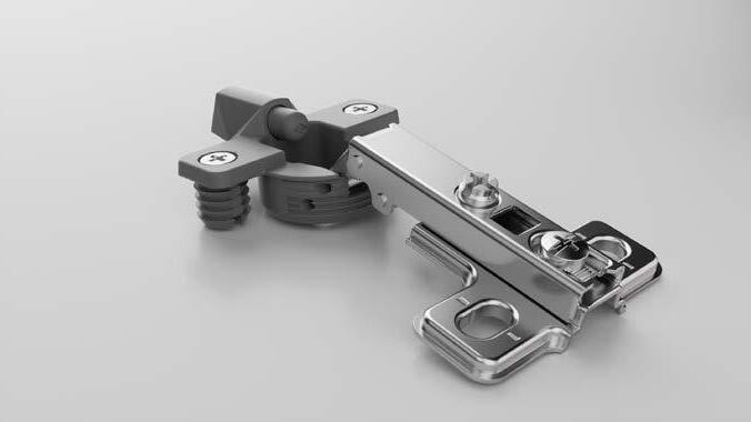
QL Mini is a small size hinge allowing the use on extra thin doors; the perfect solution for bathroom, bedroom and living room applications. Since the very beginning of the development process QL was designed to combine shape and functionality in one product, together with a SlowMotion Technology miniaturized and integrated into the hinge box.

The QL Mini hinge is the smallest mini hinge on the market: with Ø26mm cup size, only 23 grams, weight 35% less than other mini hinges. QL Mini is a preferable hinge for extra thin doors, such as bathroom furniture doors generally smaller than those applied on other furniture, but the performance is good enough to cover also standard doors in all usual sizes.


HIGH
QL Mini guarantees functionality at least till 40.000 opening cycles, working in an environment with a range of temperature between 5° and 50° and with high levels of humidity. Main dimensions and different body shapes are available to satisfy all the cabinet applications.
The modern trends of the furniture design require attractive aesthetics based on a perfect matching between all the cabinet components.
QL Mini is therfore available in innovative Coffee Black and standard nickel metal finishes together with a wide range of plastic box colours: white, light grey, dark grey, coffee black, black and any other the customer would like.


QL Mini was developed to meet the most important requirement for the end consumer: the pleasant effect of a soft door closing. Using a performing plastic material, we introduced the damping function without increasing the dimensions of a standard mini hinge. The SlowMotion Technology was miniaturized and integrated into the hinge box by working on a linear damper strong enough to pass the homologation test, stable at temperature from 5° till 50° C and suitable for soft and controlled movement.

PERFORMANCE
Compact dimension
Attractive aesthetics
Damper force adjustment
SlowMotion Technology miniaturized
Linear damper integrated into the hinge box

Full range of fixing systems
Modern and elegant plastic box colours
By simply rotating the damper, it is possible to adjust the force of the damper, to reduce the stroke, in accordance with a specific application. This also allows to obtain the best damping on different doors geometry.


Depth adjustment
Acting on the “A” screw it is possible to adjust the distance between the side of the cabinet and the door.
Independent side adjustment
Acting on the “B” screw it is possible to change the amount of the door covering on the side of the cabinet.
Vertical adjustment
Acting on the “C” screw of the mounting plate it is possible to adjust the door vertically.


Technical specifications:
• QL Mini hinge Coffee Black finish

• Depth of the metal cup 9.8mm
• Cup diameter 26mm
• Opening 105°
• Possibility of door drilling (K) from 3 to 6 mm

• Thickness of the door (T) from 12 to 26 mm
• Program of fixing systems with Selftapping screw and Euro screw, and Knock-in dowel
• SlowMotion Technology integrated with damper force adjustment


• Available also not damped version
 CRANK 0
CRANK 8
CRANK 15
CRANK 0
CRANK 8
CRANK 15
Technical Specifications:
• QL Mini hinge Nickel finish

• Depth of the metal cup 9.8mm
• Cup diameter 26mm
• Opening 105°
• Possibility of door drilling (K) from 3 to 6 mm

• Thickness of the door (T) from 12 to 26 mm
• Program of fixing systems with Selftapping screw and Euro screw, and Knock-in dowel
• SlowMotion Technology integrated with damper force adjustment
• Available also not damped version

CRANK 0 For lay-on doors
S T K
47, 2 105° 1,8 (K3) 0,4
CRANK 8 For partial lay-on doors
10,2 (H0) 37 T
S 47, 2 K A
CRANK 15 For inset doors
H* H*
105° 9,8 (K3) 8,4
29,3 (H4)
18,3 (H0) S T L3 7 K A
47, 2 20,8 (K3)
K=3 K=4 K=5 K=6 K=7
105°
37+L+ T 19,4
Drilling distance (k)
Drilling distance (k) T= A= A= A= A= A=
* = with H between two values get the lower one 3 4 5 6 7 11 0 10 0 2 9 0 2 8 0 2 4 7 2 4 6 2 4 6 5 4 6 4 4 6 3 6 2 6
H* Drilling distance (k) Overlay (C) Crank 15
3 4 5 6 7 1 2 4 0 2 4 -1 2 4 6 -2 4 6 -3 4 6 -4 6 -5 6 -6 -7 -8
Overlay (C) Crank 0 Overlay (C) Crank 8 * = with H between two values get the lower one
Table to determinate the minimum distance A so that a door with T thickness can open without protrusion from the cabinet and without interfering with adjacent doors.
CRANK 0 For lay-on doors
CRANK 8 For partial lay-on doors
between two values get the lower one
CRANK 15 For inset doors
between two values get the lower one
Table to determinate the minimum distance A so that a door with T thickness can open without protrusion from the cabinet and without interfering with adjacent doors.
Values given in mm
LOW DEPTH CUP FOR THIN DOORS
WIDE RANGE 3D DOOR ADJUSTMENTS
LARGE RANGE OF APPLICATION AND FIXING METHODS
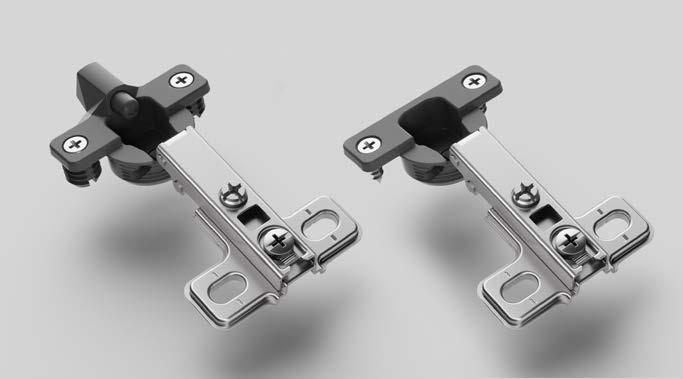
QS Mini hinge with Ø26mm cup size is compact, performing and cost efficient. QS mini hinge is the perfect solution for bathroom, bedroom and living room applications with entry level to mid-level specifications. With pre-mounted euro-screws or self-tapping screws, it is the perfect flat-pack furniture hinge.


The QS Mini hinge with Ø26mm cup size is a small hinge suitable for extra thin doors but with performance good enough to cover also standard doors in all usual sizes.

QS Mini hinge is a democratic, affordable and cost efficient solution.

QS Mini is available in a full range of cranks and angles for wooden and glass doors application. A comple program of mounting plates and fixing systems complete the offer and allow to cover every need with a specific solution.
QS Mini hinge represents a synthesis between functional needs and good value product.


QS Mini hinge is the right solution to meet the customer’s needs keeping together right quality, right performance and right price all in one.
QS Mini benefit from a 3D door adjustment system that improve significantly the way and ease of hinge use. By acting on screws it is possible to adjust frontal and vertical hinge positioning, as well as change the door covering on the cabinet side.

Depth adjustment
Acting on the “A” screw it is possible to adjust the distance between the side of the cabinet and the door.
Values given in mm
Independent side adjustment
Acting on the “B” screw it is possible to change the amount of the door covering on the side of the cabinet.
Vertical adjustment

Acting on the “C” screw of the mounting plate it is possible to adjust the door vertically.


Technical specifications:
• Depth of the metal cup 9.8mm
• Cup diameter 26mm
• Opening 105° with (K) max 4mm and (T) max 18mm
• Possibility of door drilling (K) from 3 to 6 mm


• Thickness of the door (T) from 12 to 26 mm
• Complete program of fixing system
CRANK 0 For lay-on doors
two values get the lower
CRANK 8 For partial lay-on doors
between two values get the lower one
CRANK 15 For inset doors
* = with H between two values get the lower one
Table to determinate the minimum distance A so that a door with T thickness can open without protrusion from the cabinet and without interfering with adjacent doors.
Values given in mm
Technical specifications:
• Depth of the metal cup 11.7mm
• Cup diameter 26mm
• Opening 105°
• Possibility of door drilling (K) from 3 to 5 mm


• Thickness of the door (T) from 12 to 26 mm
• Complete program of fixing system
Values given in mm

Technical specifications:
• Nylon cup
• Cup diameter 26mm
• Opening 105°
• Possibility of door drilling (K) from 3 to 6 mm


• Thickness of the glass door (T) from 4 to 5 mm

0 For lay-on doors
H T
14 48
H T
H T
14 48
C K H T
C K
C K
14 48
H=0 1 H T
H=0 1 H T
C K
Crank 8 For partial lay-on doors
H=0 1 H T
C K H T
19 H=0 9 28
19 H=0 9 28
CRANK 15 For inset doors
C K
C K H T
C K
48
48
48 H=2 18
19 H=0 9 28
48 H=2 18
48 H=2 18
48 23 Values given in mm
C K
between two values get the lower one Drilling distance (K) Drilling distance (K) Drilling distance (K)
* = with H between two values get the lower one H* H* H*
Overlay (C) Crank 0 Overlay (C) Crank 8 Overlay (C) Crank 15

Technical specifications:
• Nylon cup
• Cup diameter 26mm
• Opening 105°
• Possibility of door drilling (K) from 3 a 5 mm

• Thickness of the glass door (T) from 4 to 5 mm

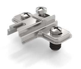
Metal cruciform mounting plate. Selftapping screw fixing. Vertical adjustment. Screws are provided on demand.
Height Material Code
H0 Steel 52.QCW0.M*.0010000
H2 Steel 52.QCW0.M*.0210000
H4 Steel 52.QCW0.M*.0410000
H6 Steel 52.QCW0.M*.0610000
Metal cruciform mounting plate. Euro screws premounted. Vertical adjustment.


Height Material Code
H0 Steel 52.QCE.^.M*.0010000
H2 Steel 52.QCE.^.M*.0210000
H4 Steel 52.QCE.^.M*.0410000
H6 Steel 52.QCE.^.M*.0610000
Metal cruciform mounting plate. Premounted selftapping screws Ø4.7mm. Vertical adjustment.


Height Material Code
H0 Steel 52.QCWP.M*.0010000
H2 Steel 52.QCWP.M*.0210000
H4 Steel 52.QCWP.M*.0410000
H6 Steel 52.QCWP.M*.0610000
* colour code: 5 = Nickel / 2 = Coffee Black
Metal cruciform mounting plate. Fixing by expanding dowels Ø5mm. Vertical adjustment.
Height Material Code
H0 Steel 52.QCX.^.M*.0010000
H2 Steel 52.QCX.^.M*.0210000
H4 Steel 52.QCX.^.M*.0410000
H6 Steel 52.QCX.^.M*.0610000
* colour code: 5 = Nickel / 2 = Coffee Black
Metal cruciform mounting plate. Knock-in fixing with dowels Ø8mm. Vertical adjustment.
Height Material Code
H0 Steel 52.QCD8.M*.0010000
H2 Steel 52.QCD8.M*.0210000
H4 Steel 52.QCD8.M*.0410000
H6 Steel 52.QCD8.M*.0610000
* colour code: 5 = Nickel / 2 = Coffee Black
Metal cruciform mounting plate. Knock-in fixing with dowels Ø10mm. Vertical adjustment.
Height Material Code
H0 Steel 52.QCD0.M*.0010000
H2 Steel 52.QCD0.M*.0210000
H4 Steel 52.QCD0.M*.0410000
H6 Steel 52.QCD0.M*.0610000
* colour code: 5 = Nickel / 2 = Coffee Black


Height Material Code
H0 Steel 52.QAE.^.M*.0010000
H2 Steel 52.QAE.^.M*.0210000
H4 Steel 52.QAE.^.M*.0410000
H6 Steel 52.QAE.^.M*.0610000
* colour code: 5 = Nickel / 2 = Coffee Black
Height Material Code
H0 Steel 52.QAWP.M*.0010000
H2 Steel 52.QAWP.M*.0210000
H4 Steel 52.QAWP.M*.0410000
H6 Steel 52.QAWP.M*.0610000
* colour code: 5 = Nickel / 2 = Coffee Black
Height Material Code
H0 Steel 52.QAX.^.M*.0010000
H2 Steel 52.QAX.^.M*.0210000


H4 Steel 52.QAX.^.M*.0410000
H6 Steel 52.QAX.^.M*.0610000
* colour code: 5 = Nickel / 2 = Coffee Black
Height Material Code
H0 Steel 52.QAD8.M*.0010000
H2 Steel 52.QAD8.M*.0210000
H4 Steel 52.QAD8.M*.0410000
H6 Steel 52.QAD8.M*.0610000
* colour code: 5 = Nickel / 2 = Coffee Black
Height Material Code
H0 Steel 52.QAD0.M*.0010000
H2 Steel 52.QAD0.M*.0210000

H4 Steel 52.QAD0.M*.0410000
H6 Steel 52.QAD0.M*.0610000
* colour code: 5 = Nickel / 2 = Coffee Black
Colour Code
chrome
Colour Code Bright chrome 51.0150.05.01D.00 Matt chrome 51.0150.0G.01D.00 Black RAL
9005
6.3 10 Steel Nickel 1A075029350CF


6.3 12 Steel Nickel 1A075108250CF
6.3 14 Steel Nickel 1A075108150CF
6.3 10 Steel Coffee Black 1A000013310002C
6.3 12 Steel Coffee Black 1A000013510202C
6.3 14 Steel Coffee Black 1A000013510302C
Selftapping screws with Pozi drive head, nickel for hinge and mounting plate fixing.


Ø Length Material Code
4 12.5 Steel Nickel 1A035034150CF
4 15.5 Steel Nickel 1A035034250CF
4 12.5 Steel Coffee Black 1A000013350202C
4 15.5 Steel Coffee Black 1A000013350302C
Euro screws with Pozi drive head, nickel for mounting plate fixing.

12 Steel 1A075130050CF 6.3 12 Steel Coffee Black 1A000013630002C
Dowel in nylon for hinge fixing.
Ø Length Material Code 10 12 Nylon 2H011070530CF
8 11 Nylon 2H000449003CF
L Ø
Values given in mm