Shaft Alignment Methods

Page 1


Shaft Alignment Methods

FSA Knowledge Series

DISCLAIMER

While the FSA makes every reasonable attempt to ensure that the information contained in this document is accurate and current, the FSA, its officers, directors, volunteers, and authorized agents are not responsible for any errors or omissions contained therein nor are they responsible for any results obtained from the use of or reliance upon its content. All information is provided “AS IS,” with no guarantee of completeness, accuracy, timeliness or of the results obtained, and without warranty of any kind, express or implied. In no event shall FSA or its officers, directors, volunteers, or authorized agents be liable to you or anyone else for any decision made or action taken in reliance on the information con tained herein or for any for any consequential, indirect, special, or similar damages, even if advised of the possibility of such damages. The informa tion contained in this document is for informational purposes only and does not constitute professional advice. It also includes references to certa in standards that may change over time and should be interpreted only in light of particular circumstances. It is your sole responsibility to confi rm the current state of any referred to standards. FSA reserves the right to modify or update the document content and to modify this Disclaimer at any t ime, effective upon posting of an updated version of this Disclaimer.

© (April, 2023), Fluid Sealing Association. All Rights Reserved.

This Fluid Sealing Association Knowledge Series training provides an overview of equipment shaft alignment information, including:​

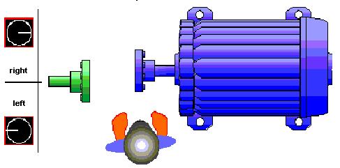
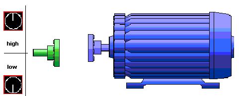
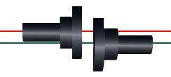
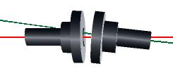
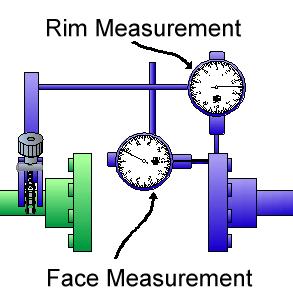
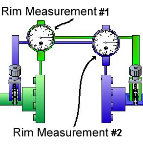
▪ Measuring misalignment
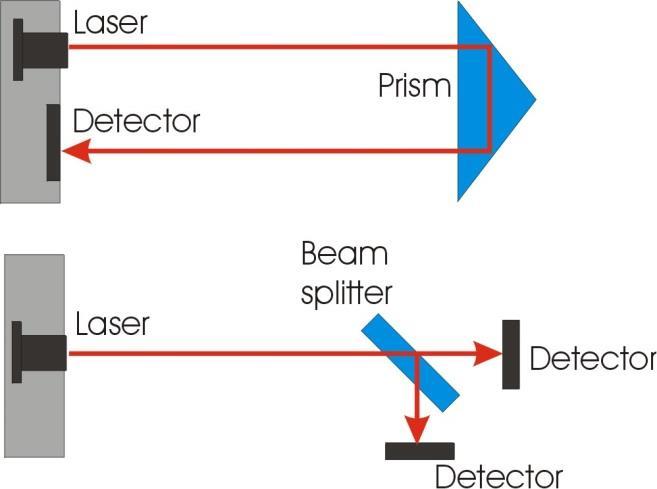
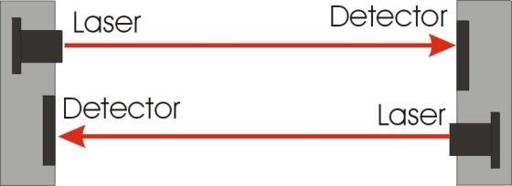
▪ Alignment methods

▪ Correlation between equipment alignment and machine life

Rotational Centers

▪ All shafts, whether they are straight or bent, rotate on an axis called the rotational center.

▪ The rotational center forms a straight line

Co-Axial Shafts

▪ Two shafts are said to be co-axial when their respective rotational centers form a single axis.

Measuring Misalignment

▪ Machines are designated as stationary and movable.

Stationary

Movable

Measuring Misalignment

▪ The rotational center of the stationary machine is a datum or reference line.

Measuring Misalignment

▪ Misalignment is determined by finding the position of the movable rotational centerline in relation to the stationary centerline in two planes.

▪ Viewed from the top - Horizontal Misalignment

▪ Viewed from the side - Vertical Misalignment

Measuring Misalignment

▪ Lateral Misalignment (Parallel Offset)

▪ Angular Misalignment

▪ Axial Misalignment

Alignment Methods

▪ With all alignment methods - measurements are taken at the shaft ends or coupling hub.

Alignment Methods

▪ Misalignment is corrected at the feet.

Alignment Methods

▪ How far & where the feet move is calculated from measurements taken at the coupling or shaft ends

Different Ways of Aligning Shafts

Mechanical Methods

Straight edge / feeler gauge

▪ Radial misalignment

▪ Determine offset using straight

▪ edge & feeler gauges

▪ Angular misalignment

▪ Measure the gap 180° apart

Dial Indicator Methods

▪ Rim face method
▪ Reverse rim method

Rim Face Alignment Method

▪ Rim dial gauge measures radial misalignment (offset)

▪ Face dial measures angular misalignment

Reversed Rim Alignment Method

▪ Tradition method

▪ Both dials measure offset on the rim

○ Radial misalignment - difference between the 2 readings

○ Angular misalignment - slope between the 2 readings

Laser Systems

▪ Single laser - single or double detectors
▪ Twin lasers - twin detectors

Comparative Analysis

0.01mm / 0.004”

0.5mm / 0.020”

Method of Alignment

0.001mm / 0.0004”

Three Stages of Alignment

▪ Pre-alignment

▪ Off site preparations - check machine specifications

▪ On site preparations - visual checks of machine

▪ On site actions - check condition of foundations’

▪ Rough-alignment

▪ Ensure the shafts are aligned “in-the-ballpark”

▪ Precision alignment

▪ Use laser alignment system

▪ Check for ‘Soft foot’

▪ Three phases: Measure, Align and Document (MAD)

Turn static files into dynamic content formats.

Create a flipbook
Issuu converts static files into: digital portfolios, online yearbooks, online catalogs, digital photo albums and more. Sign up and create your flipbook.
Shaft Alignment Methods by fluidsealing - Issuu