While the FSA makes every reasonable attempt to ensure that the information contained in this document is accurate and current, the FSA, its officers, directors, volunteers, and authorized agents are not responsible for any errors or omissions contained therein nor are they responsible for any results obtained from the use of or reliance upon its content. All information is provided “AS IS,” with no guarantee of completeness, accuracy, timeliness or of the results obtained, and without warranty of any kind, express or implied. In no event shall FSA or its officers, directors, volunteers, or authorized agents be liable to you or anyone else for any decision made or action taken in reliance on the information con tained herein or for any for any consequential, indirect, special, or similar damages, even if advised of the possibility of such damages. The informa tion contained in this document is for informational purposes only and does not constitute professional advice. It also includes references to certa in standards that may change over time and should be interpreted only in light of particular circumstances. It is your sole responsibility to confi rm the current state of any referred to standards. FSA reserves the right to modify or update the document content and to modify this Disclaimer at any t ime, effective upon posting of an updated version of this Disclaimer.
This Fluid Sealing Association Knowledge Series training presentation introduces the basic operation and construction of mechanical seals. This section includes:
▪ Essential elements of a mechanical seal
▪ Effective forces in a mechanical seal
▪ Leakage of a liquid lubricated mechanical seal
▪ Power Consumption of a liquid lubricated mechanical seal
▪ Lubrication regimes of liquid lubricated mechanical seals
▪ Seal Balance
Essential Elements of a Mechanical Seal
Seal faces: one rotating with the shaft and one stationary in the pump casing, cover or flange.
Secondary seals: one to seal the rotating face to the shaft and one to seal the stationary face to the pump cover or flange.
Metal parts: to transmit torque and to provide an axial mechanical force to load the faces
Gland Plate
Essential Requirements of a Mechanical Seal
Essential requirements for proper operation of a mechanical seal
▪ Seal faces must be flat and polished
▪ Seal faces must be installed perpendicular to the shaft
▪ Spring force must be sufficient to maintain contact of the faces
The Fluid in the Pump and Seal Area
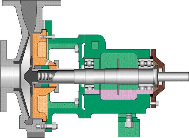
Typical Pump Cross-section
Compromise of Leakage and Wear
Key point: the fluid contacts the seal faces and other parts in wide open areas, in very small gaps and at the exit of the seal faces. Pressure and temperature of the fluid will depend on its location and determine its respective state, i.e. liquid, gaseous, solid or a mixture.
Sealed
Leakage and Wear
A few facts about the leakage (and wear) behavior of contacting mechanical seals
▪ It is essential for proper lubrication and low wear of the faces
▪ Normal leak rates range between immeasurably small to steady drips or temporary to even small streams. Some seals leak some of the time, some seals never leak (measurably), and some leak all the time. Leakage patterns can be constant, progressive or erratic in nature.
▪ It can be in liquid, gaseous and/or solid state
▪ Successful contacting seals tend to have very low wear rates and low leakage rates
Leakage and Wear
▪ Some form of contact is necessary for low leakage rates. Non-contacting or “full lift off” seals (hydrostatic or hydrodynamic tend to have visible and sizably larger leakage rates).
▪ The large majority of mechanical seals never wear out and are removed from service for some other reason.
▪ Seal failures occur for a wide range of reasons. Some failures occur as an interaction with the tribology of the interface.
Effective Forces in a Mechanical Seal
▪ Axial and radial forces
Closing and opening forces
Hydro static and hydrodynamic forces
Ac = Hydraulically Closing Area
Ao = Opening Area
P1 = Sealed Pressure
P0 = Atmospheric Pressure
(1) Spring and Hydraulic Closing Forces
(2) Lubricating Film Thickness
(3) Pressure Curve in Static Condition
(4) Linear Pressure Drop
(5) Pressure Curve with Hydrodynamic Components
Leakage
Leakage of a liquid lubricated mechanical seal
Key point: leakage rate Q strongly depends on the gap height h
Leakage creates the lubricating fluid film that prevents a mechanical seal from overheating. In order to maintain an acceptable leakage rate (Q), a stable gap/fluid film is required.
The gap height is determined by several factors: materials, manufacturing quality, lubrication regime, face distortions
The leak rate of a contacting seal is also influenced by other pump related factors such as run outs and vibration levels.
Power Consumption
Power consumption of a liquid lubricated mechanical seal
▪ Face friction, churning and soak in heat
▪ Flush to dissipate the heat in order to control the gap temperature
▪ Coefficient of friction can swing considerably during operational transients
▪ The key is to maintain the gap profile as parallel as possible, i.e. minimize distortions
Flush Flow Heat Soak from Hot Product Heat from Churning of Rotating Parts
Typically, the required flush flow rate is based upon a max ΔT of 20F
Net Contact Force
Coefficient of Friction
Sliding Velocity
Frictional Heat Heat Generation and Dissipation
Lubrication Regimes
The duty parameter is a tool to evaluate the severity of an application and the expected leakage behavior of a mechanical seal. It is a dimensionless quantity for the tribological characterization of the operating conditions of a mechanical seal.
Seal Balance
Balancing a mechanical seal reduces the axial face contact force which allows higher pressure to be sealed.
▪ Seal balance is defined as the ratio (k) of 2 geometric areas; the hydraulic closing (Ac) and opening contact area (Ao)