

TITAN DW THE ULTIMATE TWIN WALL Multi Fuel Flue System Twin Wall Insulated Flue


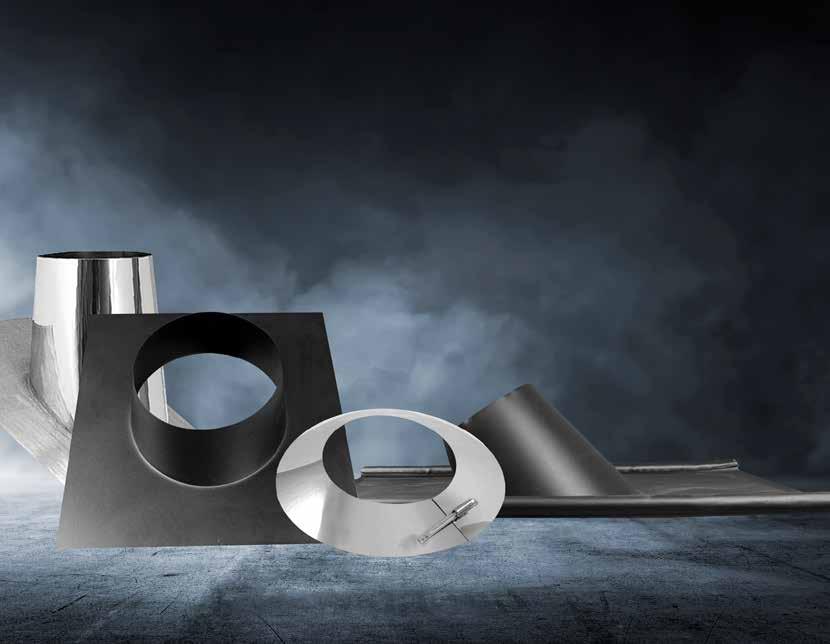
New and exclusive range.
Our Titan flue system includes new and improved components such as a wider locking band for a more secure seal and grip of your flue system, 3 meters unsupported superior structure and push to fit locking system.
All twin wall products are HETAS approved and come with a 25 year guarantee. They have all been tested to comply with all UK building regulations.


Our TITAN DW Twin Wall Flue Systems are German manufactured, engineered in both Spain and in Germany. The high-temperature resistant twin-wall system they produce is made from 304 outer (0.4-0.6mm) and 316 inner (0.4-0.6mm) stainless steel. The twin-wall system is densely packed with rigid mineral wool insulation, of 25mm thickness (120kg/m3) designed to maintain the heat inside the system and create a better draw.
TITAN DW is a multi fuel, twin wall insulated stainless steel flue system suitable for all applications in negative and positive pressure, including condensing (joint seals).
Designed for use with all gas, oil, pellet, wood, coal domestic, commercial or industrial appliances. Maximum constant working temperature 600° C and short firing up to 700° C with thermal shock testing up to 1000° C.
Available in 130mm (5”) - 300mm (12”). Any larger sizes can be ordered in up to 600mm internal diameter.
Please note: all sizes are based on the internal measurement of the flue. The external size will be 2” bigger than the internal measurement.
All of the twin-wall system have a stainless steel finish. However, these can be powder coated to most BS or RAL colour codes if required.
Standard floor standing Boiler:
TITAN DW is the solution for small commercial and industrial standard natural draft or pressure jet boilers. TITAN is suitable for wet conditions, with a capillary break in every joint. Depending on the kind of fuel and sulphur content alternative inner wall stainless steel alloys are available under request. Please consult first your national installation guidances and regulations before ordering.
CE Designation: T400 N1 V2-L50040 O30
Condensing boilers in cascade:

TITAN DW can be installed to fit modern condensing appliances in cascade. using high quality silicone joints in every component TITAN can hold positive pressure till 200 pa. a slope of 3° minimum is compulsory in horizontal runs, therefore the use of Tees and elbows in 87° is needed. The use of drain points in the most critical parts of the installation is recommended. The special designed header tees are neccessary when connecting multiple appliances into a common Header, these are fully welded and guarantee the water resistance of the installation. Please read our technical manual and installing instructions or contact our technical department for installation advise.
CE Designation: T200 P1 W V2-L50040 O00
A typical application for the TITAN DW chimney system are biomass boilers. Heating with biomass a CO2 neutral alternative for individual houses, apartments or office buildings TITAN gives the solution for the smoke exhaust. TITAN DW is tested to 600° C continous operating temperature and soot fire tested at 1000° C and has the highest corrosion resistance level V3.
Please note that frequent cleaning and maintenance of the chimney system (specially with solid fuel) will extend the lifetime of the product. Titan DW provides a 25 year warranty.
CE Designation: T600 N1 V3-L50040 G70

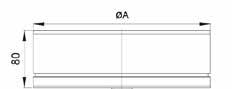
Used to adapt from single skin stove pipe to the twin-wall system. Stove Adaptor

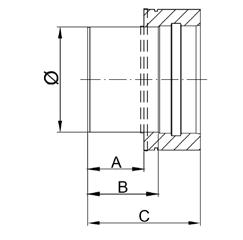
5” 6” 7” 8” 10” 12”
Ø 130 150 180 200 250 300 A 80 80 80 80 80 80 B 100 100 100 100 100 100 C 160 160 160 160 160 160
Used to adapt from twin-wall to the single skin stove pipe. Stove Adaptor
5” 6” 7” 8” 10” 12”
Ø 130 150 180 200 250 300 A 80 80 80 80 80 80 B 100 100 100 100 100 100 C 160 160 160 160 160 160
Stove Adaptor
Used to increase from smaller diameter stove pipe to larger internal diameter twin-wall system.
5” 6” 7” 8” 10” 12”
Ø 130 150 180 200 250 300 A 150 180 200 250 300 350
Stove Adaptor
Used to decrease from larger diameter stove pipe to smaller internal diameter twin-wall system.
5” 6” 7” 8” 10” 12”
Ø 130 150 180 200 250 300
A 100 130 150 180 200 250
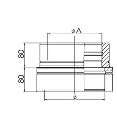
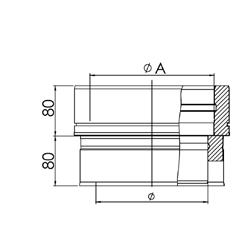
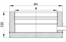
Twin-Wall Adaptor
Used to adapt from Boiler to the twin-wall system.
5” 6” 7” 8” 10” 12”
Ø 130 150 180 200 250 300
A 180 200 230 250 300 350
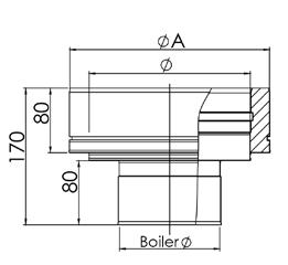
Used to adapt from twin-wall to the a boiler system. Twin-Wall Adaptor
5” 6” 7” 8” 10” 12”
Ø 130 150 180 200 250 300
A 180 200 230 250 300 350
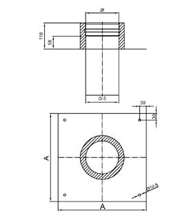
Twin-Wall Adaptor
Used to adapt from flexible liner to the twin wall system. With the addition of an anchor plate which can act as a load bearing support for the system.
5” 6” 7” 8” 10” 12”
Ø 130 150 180 200 250 300
A 400 400 400 400 400 450
Our system has been tested in different scenarios to proof different combinations of temperature, pressure and corrosion resistance.
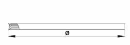
1000mm - 500mm - 250mm
The lengths can be used internally and externally to achieve the required height for the system and push-fit together with the locking bands provided.
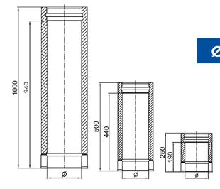
1000mm starter lengths with a 1mm internal thickness are also available (adaptor not included).
5” 6” 7” 8” 10” 12”
Ø 130 150 180 200 250 300
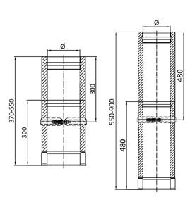
370mm - 550mm 550mm- 900mm
It is recommended that the adjustable lengths are used internally to achieve the required height for the system when an in-between size is needed. Again, these push-fit together with the locking bands provided.
They are not recommended for use between ceilings or roof timbers. Extra insulation is provided to fill the void in the adjustable once fitted.
5” 6” 7” 8” 10” 12”
Ø 130 150 180 200 250 300
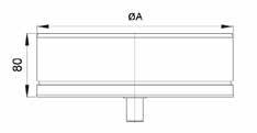
Length used for draining any condensation or liquid residue from the chimney. This item can also be installed vertically or horizontally.
5” 6” 7” 8” 10” 12”
Ø 130 150 180 200 250 300
ØA 180 200 230 250 300 350
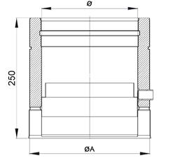
With Door 40PA & 200PA
Length to be used internally to achieve required height and easy access for cleaning.
5” 6” 7” 8” 10” 12”
Ø 130 150 180 200 250 300
A 330 360 360 360 360 400
B 270 300 300 300 300 340 C 100 130 130 130 130 150
Length
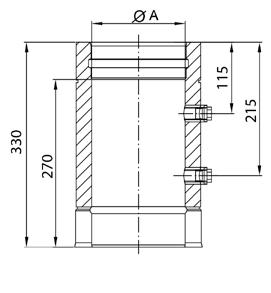
Length With Measuring Adaptor is used for checking the chimney draught, flue temperature & combustion efficiency of the heating appliance.½” port with plug to prevent leakage.
5” 6” 7” 8” 10” 12”
Ø 130 150 180 200 250 300 A 180 200 230 250 300 350
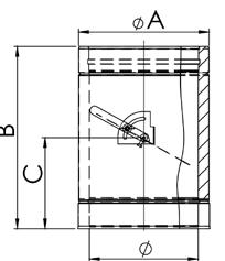
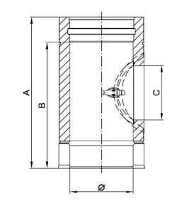
Length to be used to control the draft within the chimney. Length
5” 6” 7” 8” 10” 12”
Ø 130 150 180 200 250 300
A 180 200 230 250 300 350 B 300 320 350 370 420 470 C 150 160 175 185 210 235
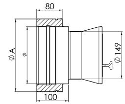
The adaptor fits into the branch of the Twin Wall Insulated 90° Tee, It is used to control excess draft for oil/solid fuel/biomass.
5” 6” 7” 8” 10” 12”
Ø 130 150 180 200 250 300

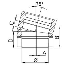
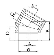
The bend is used to offset the flue system in 30° direction required for installation.
5” 6” 7” 8” 10” 12”
Ø 130 150 180 200 250 300 A 21 22 24 26 29 32 B 139 144 151 156 169 181 C 42 45 49 51 58 65
D 102 105 109 111 118 125
The bend is used to offset the flue system in 45° direction required for installation.
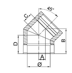
5” 6” 7” 8” 10” 12”
Ø 130 150 180 200 250 300 A 39 42 46 49 57 64 B 154 161 172 179 197 214 C 55 59 66 70 80 90 D 115 119 126 130 140 150
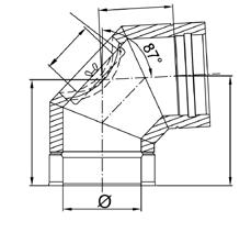
The bend is used to offset the flue system in 87° direction required for installation. Locking band is included.
5” 6” 7” 8” 10” 12”
Ø 130 150 180 200 250 300 A 191 200 215 224 248 272 B 198 208 223 233 258 283 C 131 140 155 164 188 212 D 114 118 124 128 138 148
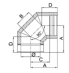
The bend is used to offset the flue system in 90° direction required for installation. Locking band is included.
5” 6” 7” 8” 10” 12
Ø 130 150 180 200 250 300 A 196 206 221 231 256 281
B 115 123 135 144 164 185 C 136 146 161 171 196 221
D 115 119 126 130 140 150
A
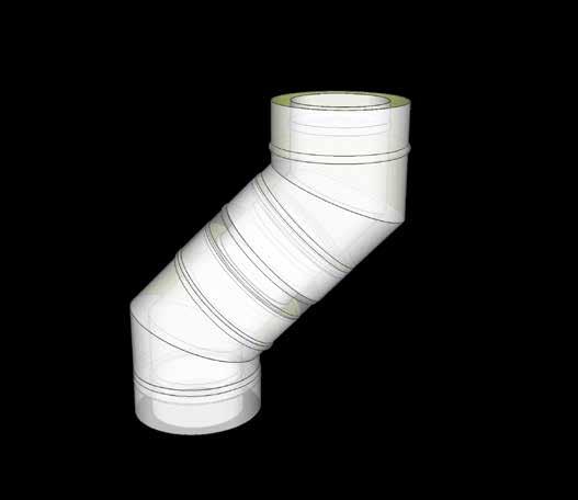
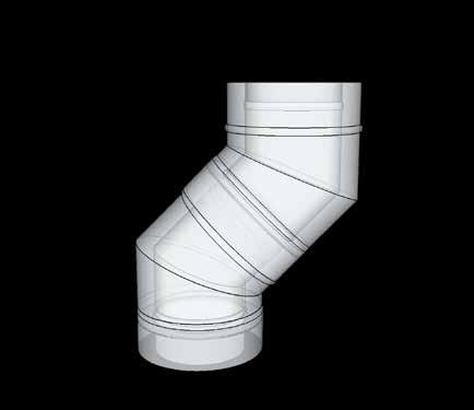
These measurements are required when the installation needs to rotate in one direction and then another. Shown are the measurements for the offsets of bends both with and without lengths in-between.
Length
B A
B
250mm length 500mm Length
Length
B
ELBOW 5” 6” 7” 8” 10” 12” 15° A 81 82 83 84 85 87 B 427 432 440 445 458 471 30° A 169 172 176 179 185 192 B 441 451 466 476 501 526 45° A 258 264 272 278 293 308 B 432 447 468 482 517 553
ELBOW 5” 6” 7” 8” 10” 12” 15° A 146 147 148 148 150 152 B 668 673 681 686 699 712 30° A 294 297 301 304 310 718 B 658 668 683 693 718 743 45° A 435 440 449 455 470 484 B 609 623 645 659 694 729
1000mm length
with elbow with elbow with elbow
ELBOW 5” 6” 7” 8” 10” 12” 15° A 32 33 34 34 36 38 B 243 248 256 261 274 287 30° A 74 77 81 84 90 97 B 277 287 302 312 337 362 45° A 123 129 138 144 159 173 B 298 312 333 348 383 418 A
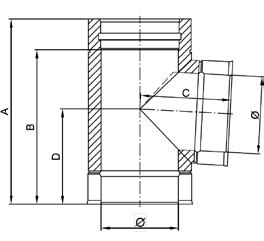
The tee pieces come complete with locking bands.
5” 6” 7” 8” 10” 12”
Ø 130 150 180 200 250 300
A 416 446 486 516 586 656 B 356 386 426 456 526 596 C 295 319 356 380 440 500
D 209 226 251 269 311 354
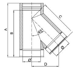
The tee pieces come complete with locking bands.
5” 6” 7” 8” 10” 12”
Ø 130 150 180 200 250 300
A 356 376 406 426 476 526 B 296 316 346 366 416 466 C 183 193 209 220 246 272
D 183 193 209 220 246 272
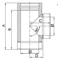
The tee pieces come complete with locking bands.
5” 6” 7” 8” 10” 12”
Ø 130 150 180 200 250 300
A 356 376 406 426 476 526 B 296 316 346 366 416 466 C 178 188 203 213 238 263
D 118 128 143 153 178 203
Allows access to the system for sweeping and inspection.
Allows access to the system for sweeping and inspection and drainage.
Allows access to the system for sweeping and inspection and drainage.
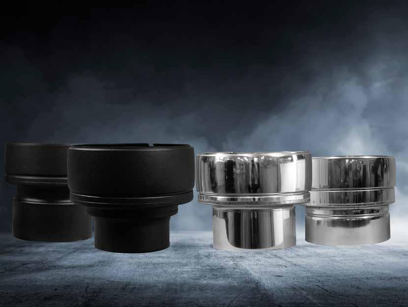
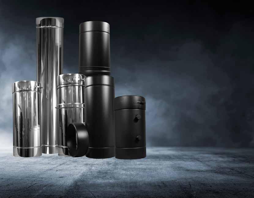
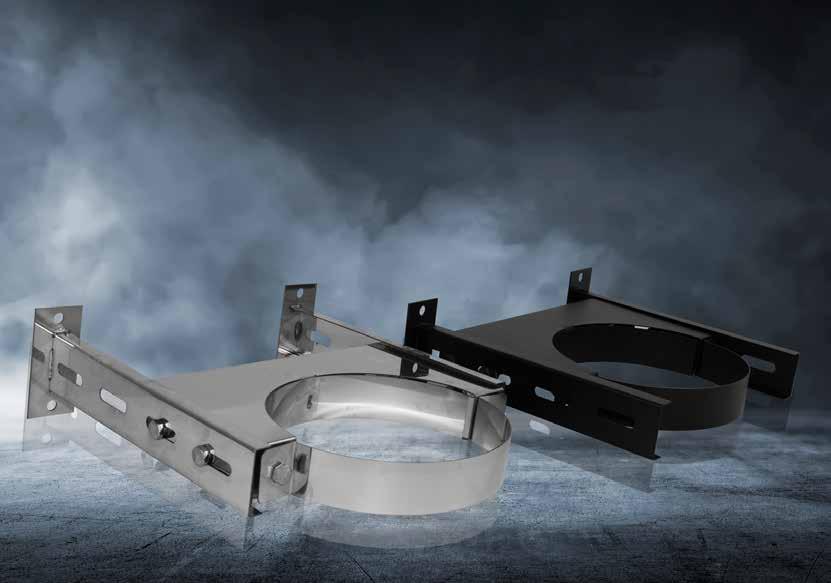
Our Stainless Steel & Matt Black Systems are fully interchangable with each other to allow you to create a more stylish installation.
Intermediate
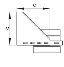
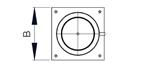
Used for additional support at the base of the external installation.
5” 6” 7” 8” 10” 12”
Ø 180 200 230 250 300 350
A 260 280 310 330 380 430
B 140 150 165 175 200 225
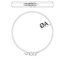
Used in conjunction with Guy Wire (not supplied) to support the run of the twin-wall if it is over 1.5mtrs above the roof. Also may be used in conjunction with rigid angle iron stays (not supplied).
5” 6” 7” 8” 10” 12”
Ø 130 150 180 200 250 300
A 180 200 230 250 300 350
Swivel Ring
Used to attach to the ceiling for additional support.
5” 6” 7” 8” 10” 12”
Ø 130 150 180 200 250 300
A 180 200 230 250 300 350
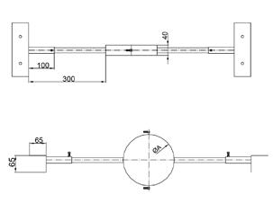
Used to support the run of the twin-wall if it is over 1.5mtrs above the roof.
5” 6”
7” 8” 10” 12”
Ø 130 150 180 200 250 300
A 180 200 230 250 300 350
B 20 20 20 20 20 20
C 1000 - 2000
Used to attach to the roof rafters for additional support.
5” 6” 7” 8” 10” 12”
Ø 130 150 180 200 250 300
A 180 200 230 250 300 350
Used to attach to the roof rafters for additional support. Adjustable
5” 6” 7” 8” 10” 12”
Ø 130 150 180 200 250 300
A 180 200 230 250 300 350
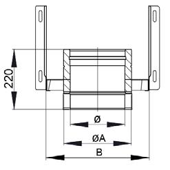
Used for load bearing support the base of the flue system. Adjustable 22.5 - 75mm
5” 6” 7” 8” 10” 12”
Ø 130 150 180 200 250 300
A 180 200 230 250 300 350
B 305 325 355 375 425 475
C 225 245 275 295 425 475
500mm
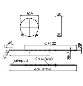
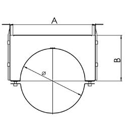
Used to provide lateral support for a twin wall system can be used for internal and external walls.
5” 6” 7” 8” 10” 12”
Ø 130 150 180 200 250 300
A 305 285 255 235 185 135
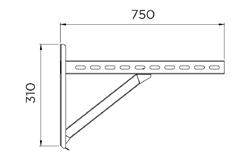
750mm
Used to provide lateral support for a twin wall system can be used for internal and external walls.
5” 6” 7” 8” 10” 12”
Ø 130 150 180 200 250 300
A 555 535 505 485 435 385
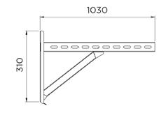
1030mm
Used to provide lateral support for a twin -wall system can be used for internal and external walls.

5” 6” 7” 8” 10” 12”
Ø 130 150 180 200 250 300 A 835 815 785 765 715 665
Used to calculate the maximum distance from the external wall.
All cross rail supports are used with the intermediate base support
5” 6” 7” 8” 10” 12”
Ø 130 150 180 200 250 300
500mm 305 285 255 235 185 135 750mm 555 535 505 485 435 385 1000mm 835 815 785 765 715 665
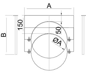
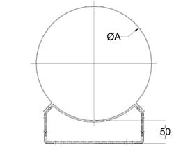
Plate
Used for additional support at any point of the external installation.
5” 6” 7” 8” 10” 12”
Ø 130 150 180 200 250 300
A 180 200 230 250 300 350
C 305 325 355 375 425 475
D 225 245 275 295 345 395
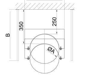
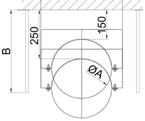
60mm - 1115mm
Used for additional support at any point of the external installation.
5” 6” 7” 8” 10” 12”
Ø 130 150 180 200 250 300
A 180 200 230 250 300 350
B 225 245 275 295 345 395
Quick Lock
Used to provide support for a twin wall system with a quick release and locking system.
5” 6” 7” 8” 10” 12”
Ø 130 150 180 200 250 300
A 180 200 230 250 300 350
Adjustable 50mm - 80mm
Used to provide lateral support for a twin wall system can be used for internal and external walls.
5” 6” 7” 8” 10” 12”
Ø 130 150 180 200 250 300
A 180 200 230 250 300 350
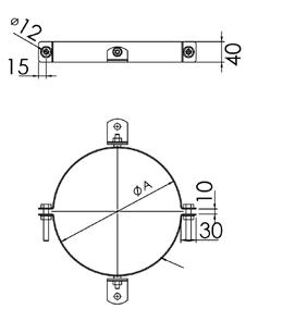
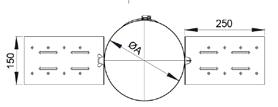
Wall Band
Adjustable 50mm - 150mm
Used to provide lateral support for a twin wall system can be used for internal and external walls.
5” 6” 7” 8” 10” 12”
Ø 130 150 180 200 250 300
ØA 180 200 230 250 300 350
A 285 310 240 360 410 460 B 225 265 325
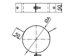
Wall Band
Adjustable 150mm - 250mm
Used to provide lateral support for a twin wall system can be used for internal and external walls.
5” 6” 7” 8” 10” 12”
Ø 130 150 180 200 250 300
ØA 180 200 230 250 300 350
A 285 310 340 360 410 460 B 325 365 425
Wall Band
Adjustable 250mm - 350mm
Used to provide lateral support for a twin wall system can be used for internal and external walls.
5” 6” 7” 8” 10” 12”
Ø 130 150 180 200 250 300
ØA 180 200 230 250 300 350
A 285 310 340 360 410 460
B 425 465 525
TITAN DW Matt Black is designed and manufactured with a high quality powder coated finish to last and never peel.
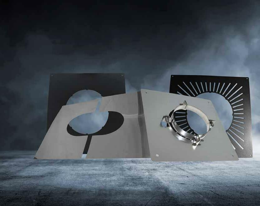
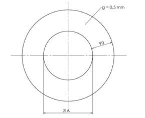
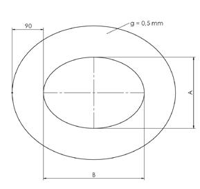
Used to neaten the installation holes in both walls and ceilings.
5” 6” 7” 8” 10” 12”
Ø 130 150 180 200 250 300
A 132 157 187 207 257 307 B 184 213 255 283 354 425
Round
Used to neaten the installation holes in both walls and ceilings.
5” 6” 7” 8” 10” 12”
Ø 130 150 180 200 250 300 A 132 157 187 207 257 307
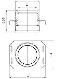
Support
Ceiling supports are load bearing and come with support collar. Used on oil and gas installations where the flue gas temperature does not exceed 250°C or for solid fuel when passing through a non combustible floor/ceiling.
5” 6” 7” 8”
ØA 180 200 230 250 A 405 410 425 430
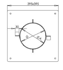
Ceiling supports are load bearing and come with support collar.
5” 6” 7” 8”
Ø 180 200 230 250 C 405 410 425 430
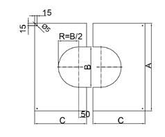
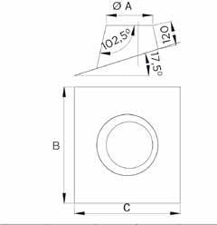
Split 0° - 30°
For use when going through a floor or ceiling at an angle.
5” 6” 7” 8” 10” 12”
Ø 130 150 180 200 250 300 A 475 495 525 545 595 645 B 183 203 233 253 303 353 C 270 280 300 310 340 370
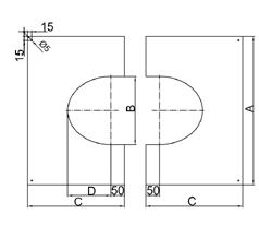
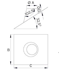
Split 31° - 45°
For use when going through a floor or ceiling at an angle.
5” 6” 7” 8” 10” 12”
Ø 130 150 180 200 250 300 A 475 495 525 545 595 645 B 183 203 233 253 303 353 C 290 310 330 340 380 410 D 107 119 136 148 177 206
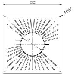
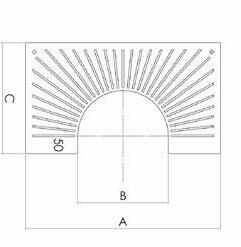
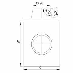
Vented
Used for enclosed upper sections to allow air ventilation.
5” 6” 7” 8” 10” 12”
Ø 130 150 180 200 250 300 A 188 208 238 258 308 358 B 194 214 244 264 314 364 C 321 346 376 396 341 391 D 375 400 430 450 395 445
For use when going through a floor or ceiling at an angle. Available in 0 - 30° and 31 - 45°.
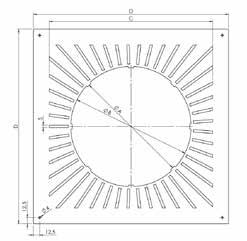
5” 6” 7” 8” 10” 12”
Ø 130 150 180 200 250 300 A 425 445 475 495 545 595 B 183 203 233 253 303 353 C 245 255 270 280 310 335
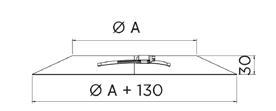
Our range of flashing come in either stainless steel or lead based to provide that all needed water tight finish to your installation.
Storm collars deflect rain from the top of the lead flashing. Seal with silicone sealant.
5” 6” 7” 8” 10” 12”
Ø 130 150 180 200 250 300 A 180 200 230 250 300 350
The stainless steel flashing acts as weatherproofing for the twin-wall system when used externally through a roof.
5” 6” 7” 8” 10” 12”
Ø 130 150 180 200 250 300
A 180 200 230 250 300 350 B 760 760 610 610 750 750 C 760 760 610 610 1000 1000
The lead-based flashings (with stainless steel upstand) act as weatherproofing for the twin-wall system when used externally through a roof.
5” 6” 7” 8” 10” 12”
Ø 130 150 180 200 250 300
A 180 200 230 250 300 350
B 1000 1000 1000 1000 1000 1000 C 760 760 760 610 750 750
The lead-based flashings (with stainless steel upstand) act as weatherproofing for the twin-wall system when used externally through a roof.
5” 6” 7” 8” 10” 12”
Ø 130 150 180 200 250 300
A 180 200 230 250 300 350
B 1000 1000 1000 1000 1000 1000 C 760 760 760 760 760 760
These terminals are especially designed to fit the Jeremias twin - wall system providing protection against rain and other elements.
5” 6” 7” 8” 10” 12”
Ø 130 150 180 200 250 300
A 180 200 230 250 300 350
B 300 345 350 400 560 675
C 105 105 155 155 155 230
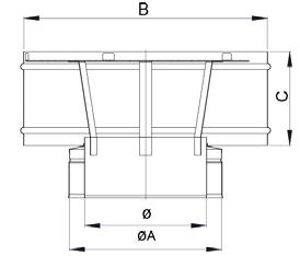
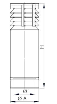
These terminals are especially designed to fit the Jeremias twin - wall system providing protection against rain and other elements.
5” 6” 7” 8” 10” 12”
Ø 130 150 180 200 250 300
A 180 200 230 250 300 350 B 260 330 360 400 500 600
H 270 270 290 300 350 395
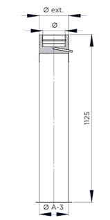
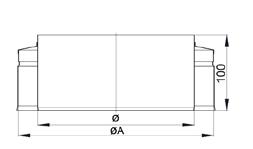
The top stub will close off the insulation at the top of the system and converts the size back to the internal diameter.
(Locking bands are NOT provided with these components)
5” 6” 7” 8” 10” 12”
Ø 130 150 180 200 250 300 A 180 200 230 250 300 350
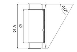
Oil Horizontal terminalWith Mesh used to fit to the the flue system as a horizontal outlet and is secured by way of a locking band
(Locking bands are NOT provided with these components)
5” 6” 7” 8” 10” 12”
Ø 130 150 180 200 250 300
A 180 200 230 250 300 350
These terminals are especially designed to fit the Jeremias twin - wall system providing protection against rain and other elements fitted with 10mm gas mesh.
5” 6” 7” 8” 10” 12”
Ø 130 150 180 200 250 300
A 180 200 230 250 300 350 B 300 345 350 400 560 675
C 105 105 155 155 155 230
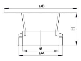
These terminals are especially designed to fit the Jeremias twin - wall system providing protection against rain and other elements.
5” 6” 7” 8” 10” 12”
Ø 130 150 180 200 250 300
A 180 200 230 250 300 350 H 315 345 375 405
Used on condensing systems
5” 6” 7” 8” 10” 12”
Ø 130 150 180 200 250 300
FSM Group Unit 6-7, Link 20, Bellingham Way, Aylesford, Kent, ME20 7HD Tel: 0844 800 6586 Email: info@fsmgroup.co.uk Copyright 2021 FSM ©
