
Previous Screen
Product: EXCAVATOR
Model: 330F LN EXCAVATOR LBN
Configuration: 330F & 330F LN Excavators
Disassembly and Assembly
326F, 329F and 330F Excavators Machine Systems Media
Travel Motor - Disassemble
SMCS - 4351-015
Disassembly Procedure
i05435976
NOTICE
Care must be taken to ensure that fluids are contained during performance of inspection, maintenance, testing, adjusting, and repair of the product. Be prepared to collect the fluid with suitable containers before opening any compartment or disassembling any component containing fluids.
Refer to Special Publication, NENG2500, "Dealer Service Tool Catalog" for tools and supplies suitable to collect and contain fluids on Cat products.
Dispose of all fluids according to local regulations and mandates.
1. Thoroughly clean the outside of the travel motor prior to disassembly.
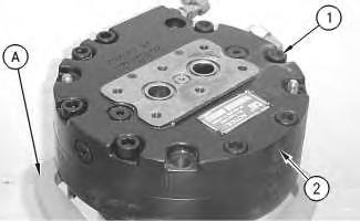
2. Fasten the travel motor in Tooling (A) in a vertical position. The weight of the travel motor is approximately 60 kg (132 lb).
3. Put an alignment mark across the head and the body of the travel motor for assembly purposes. The head must be reinstalled in the original position on the body of the travel motor.
Note: During the removal of head (2) from the travel motor, be careful not to damage the mating surfaces of the components.
Spring force can cause personal injury or death.
Do not repair until you have read the Operation and Maintenance Manual.
4. Remove bolts (1).
5. Remove head (2) from the body of the travel motor.
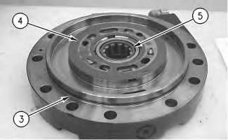
Illustration 2
6. Remove O-ring seal (3), port plate (4), and bearing (5).
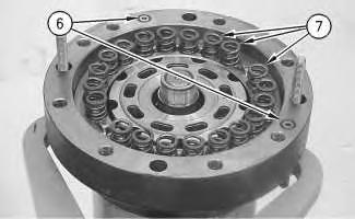
Illustration 3
g00887311
7. Remove O-ring seals (6). Remove springs (7).
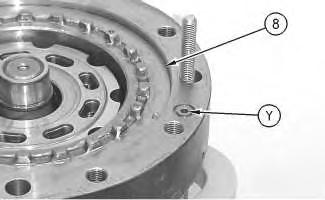
Illustration 4
g00887331
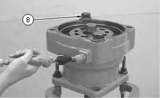
Illustration 5
A typical example of the use of Tooling (B).
g00890074
8. Place a shop towel over brake piston (8). Retain brake piston (8) with Tooling (B). Apply approximately 525 kPa (75 psi) of shop air pressure to brake release Port (Y). Make sure that the shop air pressure is free of water. Brake piston (8) will move up the piston guide, and out of the piston guide. Remove brake piston (8) from the body of the travel motor.
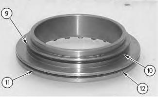
Illustration 6
g00887336
9. Remove seal (9) and backup ring (10) from the brake piston.
10. Remove seal (11) and backup ring (12) from the brake piston.
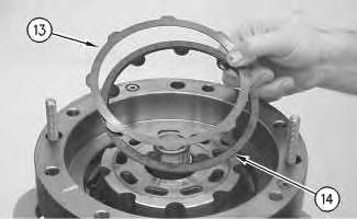
Illustration 7 g00887355
11. Remove plates (13) and friction discs (14).
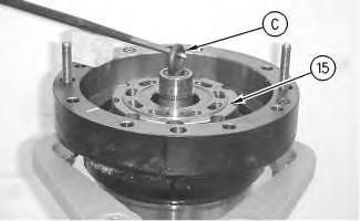
Illustration 8 g00887401
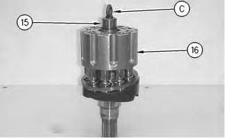
Illustration 9 g00887405
12. Install Tooling (C) into shaft (15). Use a prybar to remove the rotating assembly (16) from the housing.
13. Remove Tooling (C) from shaft (15).
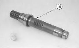
Illustration 10 g00887424
14. Remove shaft (15) from the rotating assembly .
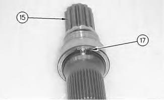
Illustration 11
g00887426
15. Use Tooling (D) in order to remove retaining ring (17) from shaft (15).
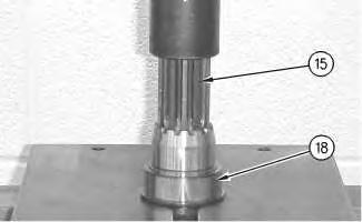
Illustration 12
g00887445
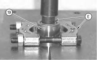
Illustration 13
g00887463
16. Install shaft (15) into a suitable press. Remove bearing race (18) from the shaft.
17. Rotate shaft (15). Install shaft (15) into a suitable press. Install Tooling (E). Remove bearing race (19) from shaft (15).
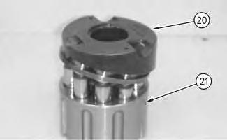
Illustration 14
g00887501
18. Remove cam plate (20) from barrel assembly (21).
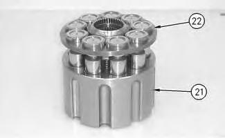
Illustration 15
g00887520
19. Remove piston assemblies and retainer plate (22) from barrel assembly (21).
Note: Place marks on the pistons and the barrel assembly. The pistons must be returned to the original position.
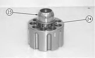
Illustration 16
g00887558
20. Remove ball (23) and springs (24).
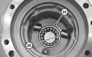
Illustration 17
21. Remove bearing (25).
22. Remove keys (26) and locating pins (not shown) from the body of the travel motor.
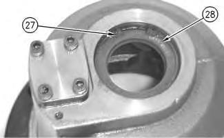
Illustration 18
g00887589
23. Rotate the housing. Use Tooling (F) in order to remove retaining ring (27).
24. Remove lip seal (28).
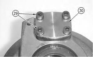
Illustration 19 g00887619
25. Remove bolts (29) and cover (30).
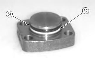
Illustration 20
26. Remove seal (31) and backup ring (32).
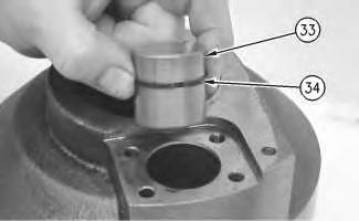
Illustration 21
g00887754
27. Remove piston actuator (33) and seal (34).
22
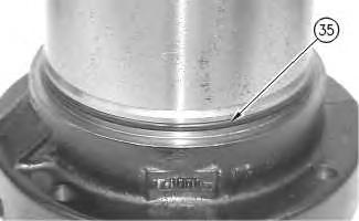
28. Remove O-ring seal (35) from the housing of the travel motor.
Copyright 1993 - 2020 Caterpillar Inc.
All Rights Reserved.
Private Network For SIS Licensees.
Sun Jul 12 21:25:51 UTC+0800 2020
Previous Screen
Product: EXCAVATOR
Model: 330F LN EXCAVATOR LBN
Configuration: 330F & 330F LN Excavators LBN00001-UP (MACHINE) POWERED BY C7.1 Engine
Disassembly and Assembly
326F, 329F and 330F Excavators Machine Systems
Media Number -UENR3313-07
Publication Date -01/09/2015 Date Updated -12/09/2018
Travel Motor - Disassemble
SMCS - 4351-015
S/N - B321-UP
S/N - EBK1-UP
S/N - ERL1-UP
S/N - FBR1-UP
S/N - GGJ1-UP
S/N - GHT1-UP
S/N - HBT1-UP
S/N - HCA1-UP
S/N - HCJ1-UP
S/N - HCK1-UP
S/N - JFR1-UP
S/N - JHF1-UP
S/N - KFA1-UP
S/N - LBN1-UP
S/N - LCG1-UP
S/N - MBX1-UP
i07505849
S/N - RCN1-UP
S/N - TMR1-UP
S/N - TPG1-UP
S/N - WBA1-UP
S/N - WGL1-UP
S/N - XFK1-UP
S/N - YHA1-UP
Disassembly Procedure
Table 1
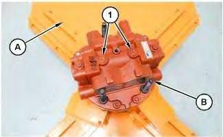
Illustration 1
1. Attach the travel motor to Tooling (A) and (B). The weight of the travel motor is approximately 70 kg (154 lb).
2. Remove plugs (1) and the O-ring seals.
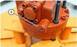
Illustration 2
g06344110
3. Remove plug (2) and the O-ring seal. Repeat for the opposite side.
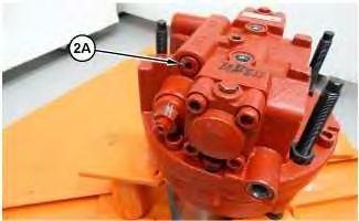
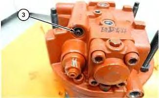
Illustration 3
g06341912
Personal injury can result from being struck by parts propelled by a released spring force.
Make sure to wear all necessary protective equipment.
Follow the recommended procedure and use all recommended tooling to release the spring force.
4. Remove plug (2A) and the O-ring seal. Repeat for the opposite side.
4
Remove spring (3).
5
6
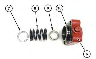
Illustration 7
Personal injury can result from being struck by parts propelled by a released spring force.
Make sure to wear all necessary protective equipment.
Follow the recommended procedure and use all recommended tooling to release the spring force.
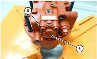
7. Remove bolts (5) and cap (6). Repeat for the opposite side.
8. Remove O-ring seal (10) from cap (6). Remove guide (9), spring (8), and washer (7) from the head assembly. Repeat for the opposite side.
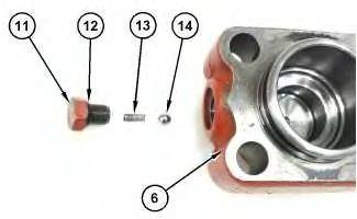
Illustration 8
Personal injury can result from being struck by parts propelled by a released spring force.
Make sure to wear all necessary protective equipment.
Follow the recommended procedure and use all recommended tooling to release the spring force.
9. Remove plug (11), O-ring seal (12), spring (13), and ball (14) from cap (6). Repeat for the other cap.
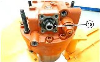
Illustration 9
10. Remove spool (15).
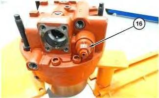
Illustration 10
g06343314
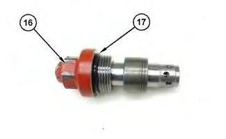
Illustration 11 g06343315
11. Remove relief valve (16). Remove O-ring seal (17) from relief valve (16).
12. Repeat for the opposite side.
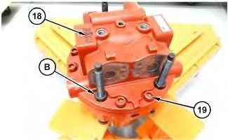
Illustration 12
g06343359
Personal injury can result from being struck by parts propelled by a released spring force.
Make sure to wear all necessary protective equipment.
Follow the recommended procedure and use all recommended tooling to release the spring force.
13. Remove the nuts of Tooling (B). Remove bolts (19) from head assembly (18).
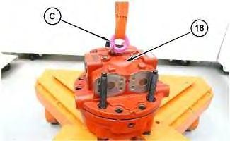
Illustration 13
g06343366
14. Use Tooling (C) and a suitable lifting device to remove head assembly (18). The weight of head assembly (18) is approximately 21 kg (47 lb).
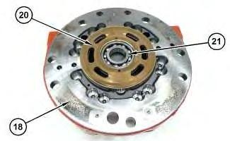
Illustration 14
g06343374
15. Remove control plate (20) and bearing (21) from head assembly (18).
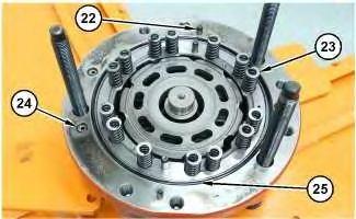
Illustration 15
16. Remove pins (22) and springs (23).
17. Remove O-ring seals (24) and (25).
g06343381
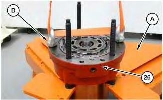
Illustration 16
g06343383
18. Use Tooling (D) and a suitable lifting device to remove housing assembly (26) from Tooling (A) and place on a suitable bench.
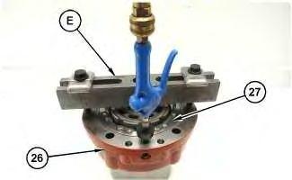
Illustration 17
g06343417
To avoid personal injury, always wear eye and face protection when using pressurized air.
19. Attach Tooling (E) to housing (26). Use air pressure to unseat brake piston (27). Remove Tooling (E) and brake piston (27).
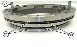
Illustration 18
g06343437
20. Remove back up rings (28) and O-ring seals (29) from brake piston (27).
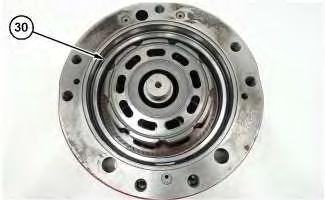
Illustration 19
21. Remove brake piston guide (30).
g06343462
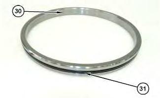
Illustration 20
g06343464
22. Remove O-ring seal (31) from brake piston guide (30).
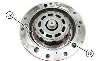
Illustration 21
g06343466
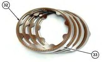
Illustration 22
g06343469
Note: Note the orientation of friction discs (32) and plates (33) for assembly purposes.
23. Remove friction discs (32) and plates (33).
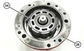
Illustration 23
g06343638
24. Remove rotating group (34) from housing (26).
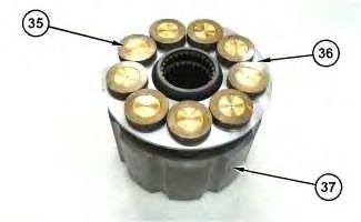
Illustration 24
g06343777
25. Remove pistons (35) and retainer (36) from barrel (37).
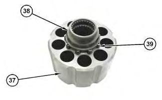
Illustration 25
g06343783
26. Remove hold down ball (38) and springs (39) from barrel (37).

Suggest:
If the above button click is invalid.
Please download this document first, and then click the above link to download the complete manual.
Thank you so much for reading
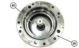
Illustration 26
g06343786
27. Remove swashplate (40) from housing (26).

Illustration 27
g06343788
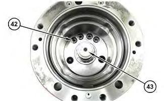
Illustration 28 g06343793
28. Remove pistons (41).
29. Remove springs (42) and shaft (43).