
Previous Screen
Product: EXCAVATOR
Model: 330D2 EXCAVATOR XDR
Configuration: 330D2 L Excavator XDR00001-UP (MACHINE) POWERED BY C7.1 Engine
Disassembly and Assembly
C7.1 Engines
Media Number -UENR0633-19
Engine Oil Pump - Install
SMCS - 1304-012
Installation Procedure
Table 1
Required Tools
NOTICE
Keep all parts clean from contaminants.
Contaminants may cause rapid wear and shortened component life.
i05292278
NOTICE
If any part of the engine oil pump is worn or damaged, the complete assembly of the engine oil pump must be replaced.
1. Ensure that all components of the engine oil pump are clean and free from wear and damage. Refer to System Operation, Testing and Adjusting, "Engine Oil Pump - Inspect"
for more information. Replace the complete assembly of the engine oil pump if any of the components are worn or damaged.

Illustration 1
g03409497
2. If necessary, follow Step 2.a through step 2.d to install cross over tube assembly (14).
a. Install new gasket (17) and new gasket (18).
b. Position cross over tube assembly (14) onto the cylinder block.
c. Install bolts (15) and bolts (16) to cross over tube assembly (14) finger tight.
d. Tighten bolts (15) and bolts (16) to a torque of 22 N·m (195 lb in).

3. If necessary, follow Step 3.a through step 3.d to assemble engine oil pump assembly (2).
a. Lubricate the internal components for the assembly of the engine oil pump with clean engine oil.
b. Install outer rotor (13) to oil pump assembly (2). Ensure that the outer rotor is installed in the outer rotor original position and orientation.
c. Install front cover assembly (12) to engine oil pump assembly (2).
d. Install bolts (11) finger tight. Tighten the bolts to a torque of 22 N·m (195 lb in).
4. Ensure that dowel (9) and dowel (10) are correctly located in the housing of engine oil pump (2).
5. Install bolts (7). Tighten the bolts to a torque of 22 N·m (195 lb in).
6. Install the assembly of engine oil pump (2) to the cylinder block. Ensure that dowel (9) and dowel (10) are correctly aligned with the holes in the cylinder block.
7. Install bolts (1) to assembly of engine oil pump (2). Tighten the bolts to a torque of 22 N·m (195 lb in).
8. Use Tooling (A) to check the backlash between idler gear and the crankshaft gear. Refer to Specifications, "Gear Group (Front)" for more information.
9. If suction pipe (5) had a support bracket, Follow Step 9.a through Step 9.e in order to install support bracket and the suction pipe.
a. Install a new gasket (3) (not shown) to suction pipe (5).
b. Install bolts (4) to suction pipe (1).
c. Position the assembly of suction pipe (5) onto oil pump (2). Tighten bolts (4) to a torque to 22 N·m (195 lb in).
d. Position bracket (8) onto cylinder block and retaining clip. Install bolt (7) to the bracket. Install bolt (6) to the retaining clip. Hand tighten the bolts.
Note: Ensure the correct location and orientation of the bracket and the retaining clip.
e. Tighten bolt (6) to a torque of 22 N·m (195 lb in).
Tighten bolt (7) to a torque of 44 N·m (32 lb ft).
Note: Ensure that the suction pipe and the bracket are not strained as the bolts are tightened.
End By:
a. Install the engine oil pan. Refer to Disassembly and Assembly, "Engine Oil Pan - Install" for the correct procedure. Copyright 1993 - 2020 Caterpillar Inc.
Wed Jul 15 12:11:33 UTC+0800 2020
Previous Screen
Product: EXCAVATOR
Model: 330D2 EXCAVATOR XDR
Configuration: 330D2 L Excavator XDR00001-UP (MACHINE) POWERED BY C7.1 Engine
Disassembly and Assembly
C7.1 Engines
Media Number -UENR0633-19
Publication Date -01/07/2015
Water Pump - Remove
SMCS - 1361-011
Removal Procedure
Start By:
Date Updated -29/10/2018
i05292437
a. Remove the fan and the fan pulley. Refer to Disassembly and Assembly, "Fan - Remove and Install" for the correct procedure.
NOTICE
Keep all parts clean from contaminants.
Contaminants may cause rapid wear and shortened component life.
NOTICE
Care must be taken to ensure that fluids are contained during performance of inspection, maintenance, testing, adjusting and repair of the product. Be prepared to collect the fluid with suitable containers before opening any compartment or disassembling any component containing fluids.
Dispose of all fluids according to local regulations and mandates.
1. Drain the coolant from the cooling system into a suitable container for storage or disposal. Refer to Operation and Maintenance Manual, "Cooling System Coolant - Change" for the correct procedure.
2. Loosen the hose clamps and remove the hose from the water pump inlet.

Illustration 1 g03434676
3. Remove bolts (4), bolts (5), and bolts (6). Identify the positions of bolts of different length.
4. Remove water pump (3) from front cover (1).
Note: If necessary, tap the water pump with a soft faced hammer in order to loosen the water pump.
5. Remove gasket (2).
Copyright 1993 - 2020 Caterpillar Inc. All Rights Reserved.
Network For SIS Licensees.
Wed Jul 15 12:12:29 UTC+0800 2020
Previous Screen
Product: EXCAVATOR
Model: 330D2 EXCAVATOR XDR
Configuration: 330D2 L Excavator XDR00001-UP (MACHINE) POWERED BY C7.1 Engine
Disassembly and Assembly
C7.1 Engines
Media Number -UENR0633-19 Publication Date -01/07/2015 Date Updated -29/10/2018
Water Pump - Install
SMCS - 1361-012
Installation Procedure Table 1
Required Tools Tool
Keep all parts clean from contaminants.
Contaminants may cause rapid wear and shortened component life.
i05292436
NOTICE
Care must be taken to ensure that fluids are contained during performance of inspection, maintenance, testing, adjusting and repair of the product. Be prepared to collect the fluid with suitable containers before opening any compartment or disassembling any component containing fluids.
Dispose of all fluids according to local regulations and mandates.
1. Ensure that the water pump is clean and free from wear and damage. If necessary, replace the water pump. Clean the gasket surface of the water pump.

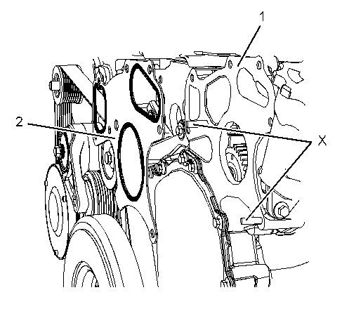
Illustration 2 g03413498
2. Clean the gasket surface of front cover (1).
3. Install Tooling (A) in Position (X).
4. Use Tooling (A) in order to align new gasket (2) to front cover (1). Install the gasket onto the front cover.
5. Align water pump (3) to Tooling (A). Install the water pump to front cover (1).
Note: Ensure that the gear of the water pump and the gear of the fuel injection pump mesh.
6. Install bolts (4), bolts (5), and bolts (6). Refer to Illustration 1. Tighten the bolts finger tight
7. Remove Tooling (A) and install the remaining bolts.

Illustration 3
8. Tighten bolts (4), bolts (5), and bolts (6) in the sequence that is shown in Illustration 3 to a torque of 22 N·m (195 lb in).
9. Install the hose to the water pump inlet. Tighten the hose clamps securely.
10. Fill the cooling system with coolant. Refer to Operation and Maintenance Manual, "Cooling System Coolant - Change" for the correct procedure.
End By:
a. Install the fan and the fan pulley. Refer to Disassembly and Assembly, "Fan - Remove and Install" for the correct procedure.
-
Wed Jul 15 12:13:24 UTC+0800 2020
Previous Screen
Product: EXCAVATOR
Model: 330D2 EXCAVATOR XDR
Configuration: 330D2 L Excavator XDR00001-UP (MACHINE) POWERED BY C7.1 Engine
Disassembly and Assembly
C7.1 Engines
Media Number -UENR0633-19
Publication Date -01/07/2015
Date Updated -29/10/2018
Water Temperature Regulator - Remove and Install
SMCS - 1355-010
Removal Procedure
NOTICE
Keep all parts clean from contaminants.
Contaminants may cause rapid wear and shortened component life.
i05292439
NOTICE
Care must be taken to ensure that fluids are contained during performance of inspection, maintenance, testing, adjusting and repair of the product. Be prepared to collect the fluid with suitable containers before opening any compartment or disassembling any component containing fluids.
Dispose of all fluids according to local regulations and mandates.
1. Drain the coolant from the cooling system to a level below the water temperature regulator, into a suitable container for storage or for disposal. Refer to Operation and Maintenance Manual, "Cooling System Coolant - Change" for the correct draining procedure.
2. Loosen the hose clamps from the upper radiator hose and disconnect the upper radiator hose from water temperature regulator housing (2).
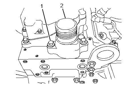
Illustration 1 g01336665
Typical example
3. Remove bolts (1) from water temperature regulator housing (2).
4. Remove water temperature regulator housing (2) from the cylinder head.
Note: Note the orientation of the water temperature regulator housing.
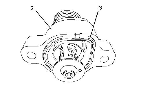
Illustration 2 g01336667
Typical example
5. Remove O-ring seal (3) from water temperature regulator housing (2).
Installation Procedure
NOTICE
Keep all parts clean from contaminants.
Contaminants may cause rapid wear and shortened component life.
1. Ensure that all components of water temperature regulator housing (2) are clean and free of wear or damage. Check the water temperature regulator for correct operation. Refer to System Operation, Testing and Adjusting, "Water Temperature Regulator - Test" for the procedure to test the water temperature regulator. If any components of the water temperature regulator housing are worn or damaged, the complete assembly must be replaced.
Illustration 3
Typical example
g01336667
2. If the original water temperature regulator housing is installed, position a new O-ring seal (3) into the groove in water temperature regulator housing (2).
A new water temperature regulator housing is supplied with a new O-ring seal.
3. Position water temperature regulator housing (2) onto the cylinder head.
Note: Ensure the correct orientation of the water temperature regulator housing.
Illustration 4 g01336665
Typical example
4. Install bolts (1). Tighten bolts (1) to a torque of 44 N·m (32.5 lb ft).
5. Connect the upper radiator hose and tighten the hose clamps.
6. Fill the cooling system to the correct level. Refer to Operation and Maintenance Manual, "Cooling System Coolant - Check" and Operation and Maintenance Manual, "Cooling System Coolant - Change" for the correct filling procedure.
1993 - 2020 Caterpillar Inc. All Rights Reserved. Private Network For SIS Licensees.
Previous Screen
Product: EXCAVATOR
Model: 330D2 EXCAVATOR XDR
Configuration: 330D2 L Excavator XDR00001-UP (MACHINE) POWERED BY C7.1 Engine
Disassembly and Assembly
C7.1 Engines
Media
-UENR0633-19
i05292294
Flywheel - Remove - Equipped with Rear Power Take-Off
SMCS - 1156-011
Removal Procedure
Table 1 Required Tools
Start By:
a. Remove the electric starting motor. Refer to Disassembly and Assembly, "Electric Starting Motor - Remove and Install" for the correct procedure.
NOTICE
Keep all parts clean from contaminants.
Contaminants may cause rapid wear and shortened component life.

Illustration 1 g02062053
1. Remove bolts from Position (X) from flywheel (1).
2. Install Tooling (A) in Position (X) to flywheel (1).
3. Use a suitable lifting device to support the flywheel. The weight of flywheel (2) is approximately 68 kg (150 lb).
4. Remove remaining bolts (2).
5. Use the lifting device to remove flywheel (1) from the engine.
6. Remove Tooling (A).
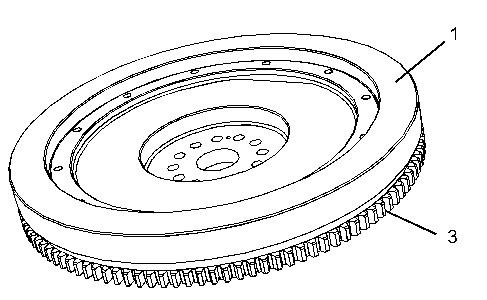
7. Inspect flywheel (1) and ring gear (3) for wear and damage. Replace any worn components or damaged components.
8. To remove flywheel ring gear (3), follow Step 8.a through Step8.b.
a. Place the flywheel assembly on a suitable support.
b. Use a hammer and a punch in order to remove ring gear (3) from flywheel (1).
Note: Identify the orientation of the teeth on the flywheel ring gear.
Previous Screen
Product: EXCAVATOR
Model: 330D2 EXCAVATOR XDR
Configuration: 330D2 L Excavator XDR00001-UP (MACHINE) POWERED BY C7.1 Engine
Disassembly and Assembly
C7.1 Engines
Media Number -UENR0633-19
i05292296
Flywheel - Remove
SMCS - 1156-011
Removal Procedure
Table 1
Required Tools
Start By:
a. Remove the electric starting motor. Refer to Disassembly and Assembly, "Electric Starting Motor - Remove and Install" for the correct procedure.
NOTICE
Keep all parts clean from contaminants.
Contaminants may cause rapid wear and shortened component life.
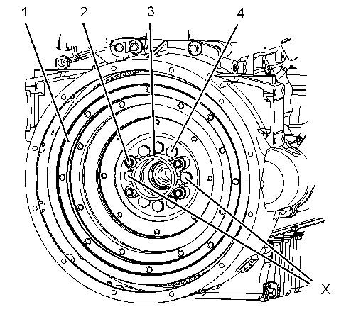
Illustration 1 g01336668
Typical example
1. Remove bolts from Position (X) from flywheel (1).
2. Install Tooling (A) in Position (X) to flywheel (1).
3. Install a suitable lifting device onto flywheel (1). Support the weight of the flywheel. The flywheel can weigh 71 kg (156 lb).
4. If necessary, remove bolts (2) that secure the housing for pilot bearing (3) to flywheel (1). Remove the housing for pilot bearing (3).
5. Remove remaining bolts (4).
6. Use the lifting device to remove the flywheel from the engine.
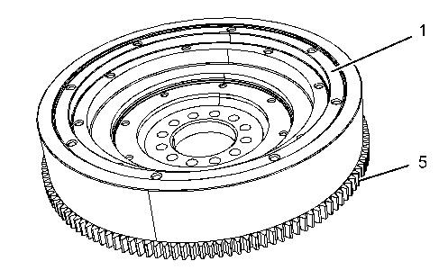
Illustration 2 g01336669
Typical example
7. Inspect flywheel (1) and ring gear (5) for wear and damage. Replace any worn components or damaged components.
8. To remove flywheel ring gear (5), follow Step 8.a through Step 8.b.
a. Place the flywheel assembly on a suitable support.
b. Use a hammer and a punch in order to remove ring gear (5) from flywheel (1).
Note: Identify the orientation of the teeth on the flywheel ring gear. Copyright 1993 - 2020 Caterpillar Inc. All Rights Reserved. Private Network For SIS Licensees.
Previous Screen
Product: EXCAVATOR
Model: 330D2 EXCAVATOR XDR
Configuration: 330D2 L Excavator XDR00001-UP (MACHINE) POWERED BY C7.1 Engine
Disassembly and Assembly
C7.1 Engines
Media Number -UENR0633-19
Flywheel - Install - Equipped with Rear Power Take-Off
SMCS - 1156-012
Installation Procedure Table 1
Keep all parts clean from contaminants.
Contaminants may cause rapid wear and shortened component life.
i05292291
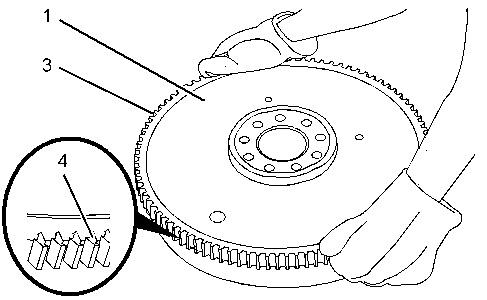
Illustration 1 g02062093
Always wear protective gloves when handling parts that have been heated.
1. If the flywheel ring gear was removed, follow Step 1.a through Step 1.c in order to install ring gear (3) to flywheel (1).
a. Identify the orientation of teeth (4) on new ring gear (3).
Note: The chamfered side of ring gear teeth (4) must face toward the starting motor when the flywheel is installed. The chamfered side of ring gear teeth ensures the correct engagement of the starting motor.
b. Heat flywheel ring gear (3) in an oven to a maximum temperature of 250 °C (482 °F) prior to installation.
Note: Do not use a torch to heat the ring gear.
c. Ensure that the orientation of ring gear (3) is correct and quickly install the ring gear onto flywheel (1).
2. Inspect the crankshaft rear seal for leaks. If there are any oil leaks, replace the crankshaft rear seal. Refer to Disassembly and Assembly, "Crankshaft Rear Seal - Install" for the correct procedure.
3. Install a suitable lifting device on flywheel (1). The flywheel can weigh 68 kg (150 lb).
4. Install Tooling (A) in Position (X) on the crankshaft.
5. Use the lifting device to position flywheel (1) onto Tooling (A).
6. Install bolts (2) to flywheel (1).
7. Remove Tooling (A) and install remaining bolts (2) to flywheel (1).
8. Use a suitable tool to prevent the flywheel from rotating. Tighten bolts (2) and (4) to a torque of 140 N·m (103 lb ft).
9. Remove the lifting device from flywheel (1).
10. Check the run out of the flywheel. Refer to Specifications, "Flywheel" for more information.
End By:
a. Install the electric starting motor. Refer to Disassembly and Assembly, "Electric Starting Motor - Remove and Install" for the correct procedure.
Previous Screen
Product: EXCAVATOR
Model: 330D2 EXCAVATOR XDR
Configuration: 330D2 L Excavator XDR00001-UP (MACHINE) POWERED BY C7.1 Engine
Disassembly and Assembly
C7.1 Engines
Media Number -UENR0633-19
Flywheel
- Install
SMCS - 1156-012
Installation Procedure
Table 1 Required Tools
Keep all parts clean from contaminants.
Contaminants may cause rapid wear and shortened component life.
i05292292

Illustration 1 g01336671
Typical example
Always wear protective gloves when handling parts that have been heated.
1. If the flywheel ring gear was removed, follow Step 1.a through Step 1.c in order to install ring gear (5) to flywheel (1).
a. Identify the orientation of teeth (6) on new ring gear (5).
Note: The chamfered side of ring gear teeth (6) must face toward the starting motor when the flywheel is installed. The chamfered side of ring gear teeth ensures the correct engagement of the starting motor.
b. Heat flywheel ring gear (5) in an oven to a maximum temperature of 250 °C (482 °F) prior to installation.
Note: Do not use a torch to heat the ring gear.
c. Ensure that the orientation of ring gear (5) is correct and quickly install the ring gear onto flywheel (1).
2. Inspect the crankshaft rear seal for leaks. If there are any oil leaks, replace the crankshaft rear seal. Refer to Disassembly and Assembly, "Crankshaft Rear Seal - Install" for the correct procedure.

Suggest:
If the above button click is invalid.
Please download this document first, and then click the above link to download the complete manual.
Thank you so much for reading
Illustration 2 g01336668
Typical example
3. Install a suitable lifting device onto flywheel (1). The flywheel can weigh 71 kg (156 lb).
4. Install Tooling (A) in Position (X) on the crankshaft.
5. Use the lifting device to position flywheel (1) onto Tooling (A).
6. If necessary, install pilot bearing (3) and bolts (2) to flywheel (1).
7. Install bolts (4) to flywheel (1).
8. Remove Tooling (A) and install remaining bolts (4) to flywheel (1).
9. Use a suitable tool to prevent the flywheel from rotating. Tighten bolts (2) and (4) to a torque of 140 N·m (103 lb ft).
10. Remove the lifting device from flywheel (1).
11. Check the run out of the flywheel. Refer to Specifications, "Flywheel" for further information.
End By:
a. Install the electric starting motor. Refer to Disassembly and Assembly, "Electric Starting Motor - Remove and Install" for the correct procedure.