
Previous Screen
Product: EXCAVATOR
Model: 330D2 EXCAVATOR HSP
Configuration: 330D2 L OEM HSP00001-UP (MACHINE) POWERED BY C7.1 Engine
Disassembly and Assembly
326D2, 329D2 and 330D2 Excavators Machine Systems
Media Number -UENR6134-08
Publication Date -01/09/2018 Date Updated -12/09/2018
Travel Motor - Disassemble
SMCS - 4351-015
S/N - DTG1-UP
S/N - EBP1-UP
S/N - EX71-UP
S/N - FEX1-UP
S/N - HSP1-UP
S/N - JFG1-UP
S/N - KER1-UP
S/N - LJE1-UP
Disassembly Procedure
Start By:
a. Remove the travel motor.
Reference: Refer to Disassembly and Assembly, "Travel Motor - Remove" in this manual.
NOTICE
Care must be taken to ensure that fluids are contained during performance of inspection, maintenance, testing, adjusting and repair of the product. Be prepared to collect the fluid with suitable containers before opening any compartment or disassembling any component containing fluids.
i01219550
Refer to Special Publication, NENG2500, "Caterpillar Dealer Service Tool Catalog" for tools and supplies suitable to collect and contain fluids on Caterpillar products.
Dispose of all fluids according to local regulations and mandates.
1. Thoroughly clean the outside of the travel motor prior to disassembly.
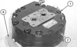
2. Fasten the travel motor to a suitable holding fixture in a vertical position. The weight of the travel motor is 60 kg (132 lb).
3. Put an alignment mark across the head and the body of the travel motor for assembly purposes. The head must be reinstalled in the head's original position on the body of the travel motor.
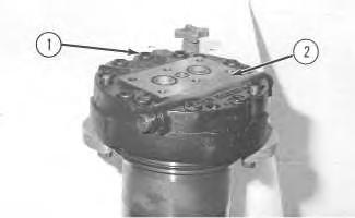
1
Note: During the removal of head (2) from the body of the travel motor, be careful not to scratch or damage the mating surfaces of the components.
4. Remove socket head bolts (1).
5. Remove head (2) from the body of the travel motor.
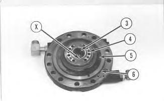
2
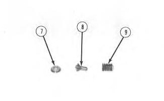
Illustration 3
6. Turn over head (2).
g00510349
7. Remove O-ring seal (6), shims (5), port plate (4), and bearing (3) from the head.
8. Remove the two check valve assemblies from the head.
Note: There is a retainer under spring (9). This retainer is a press fit in head (2). Do not remove the retainer.
9. Insert a dowel rod with a small diameter into hole (X). Tap the dowel rod with a plastic hammer in order to remove spring (9), poppet (8) and seat (7) from the head.

Illustration 4
g00510351
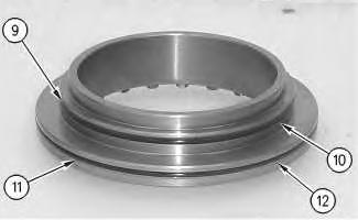
10. Remove three fittings (10) and plugs (11) from the head. Remove the O-ring seal from each fitting.
5
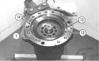
11. Remove three O-ring seals (12) and washer set (13) from the body of the travel motor.
12. Place a shop towel over brake piston (14). Retain brake piston (14) by hand, and apply approximately 525 kPa (75 psi) of shop air pressure to brake release port (Y). Make sure that the shop air pressure is free of water. Brake piston (14) will move up the piston guide, and out of the piston guide. Remove brake piston (14) from the body of the travel motor.

Illustration 6
13. Remove O-ring seal (15) from the brake piston. Remove backup ring (16) from the brake piston.
14. Remove O-ring seal (17) from the brake piston. Remove backup ring (18) from the brake piston.
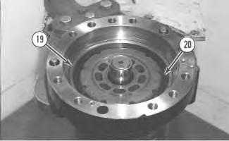
Illustration 7
15. Remove piston guide (19), five friction plates (20) and the four steel plates from the body of the travel motor.
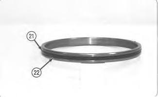
Illustration 8
g00510359
16. Remove O-ring seal (21) from the piston guide. Remove backup ring (22) from the piston guide.

Illustration 9
g00510365
Note: Do not allow the components of barrel assembly (23) to come apart during the removal from the travel motor. All of the components in the barrel assembly must be reinstalled in the component's original location.
17. Use two large screwdrivers, as shown. Slowly remove barrel assembly (23) from the body of the travel motor. Do not allow the components to fall apart.
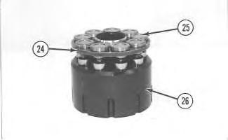
Illustration 10
Note: Shoe retainer (24) and piston shoe assemblies (25) are not serviced separately. Prior to the removal of the shoe retainer and the piston shoe assemblies from barrel (26), put identification marks on piston shoe assemblies (25) for assembly purposes. Identification marks are used to identify the piston shoe assembly's location in shoe retainer (24) and barrel (26). The piston shoe assemblies must be reinstalled in the piston shoe assembly's original bores in the shoe retainer and the barrel.
18. Remove shoe retainer (24) and piston shoe assemblies (25) from barrel (26). Separate the piston shoe assemblies from the shoe retainer.
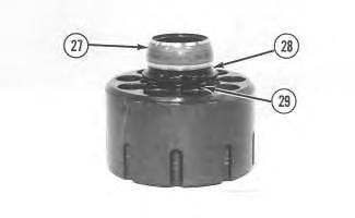
Illustration 11
g00510504
19. Remove guide (27), spacer (28) and springs (29) from the barrel.
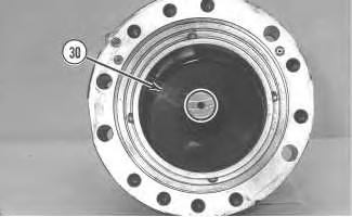
Illustration 12
g00510547
20. Remove cam plate (30) from the body of the travel motor.
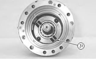
Illustration 13
g00510550
21. Remove two keys (31) and the two locating pins (not shown) from the body of the travel motor.
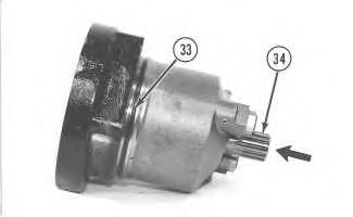
Illustration 14
g00510551
22. Remove O-ring seal (33) from the body of the travel motor.
23. Use a soft faced hammer to remove shaft assembly (34) from the body of the travel motor. Remove the shaft assembly in the direction that is indicated by the arrow. Refer to Illustration 14.

Illustration 15
24. Remove retaining rings (35) from each side of bearing (36). Push shaft (34) out of bearing (36) with a press.
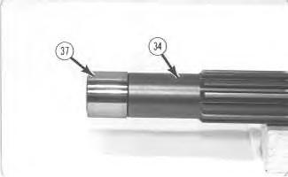
Illustration 16
25. Remove inner race (37) from shaft (34).
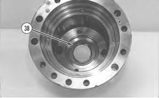
Illustration 17
g00510599
26. Remove lip seal (38) from the body of the travel motor.
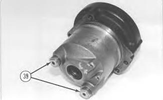
Illustration 18 g00510605
27. Remove two stoppers (39) and the two pistons from the body of the travel motor.
Copyright 1993 - 2020 Caterpillar Inc. All Rights Reserved. Private Network For SIS Licensees.
Thu Jul 16 13:45:11 UTC+0800 2020
Previous Screen
Product: EXCAVATOR
Model: 330D2 EXCAVATOR HSP
Configuration: 330D2 L OEM HSP00001-UP (MACHINE) POWERED BY C7.1 Engine
Disassembly and Assembly
326D2, 329D2 and 330D2 Excavators Machine Systems
Travel Motor - Disassemble
SMCS - 4351-015
Disassembly Procedure
Start By: A. Remove the travel motor. Refer to Disassembly and Assembly, "Travel Motor -
NOTICE
Care must be taken to ensure that fluids are contained during performance of inspection, maintenance, testing, adjusting and repair of the product. Be prepared to collect the fluid with suitable containers before opening any compartment or disassembling any component containing fluids.
Refer to Special Publication, NENG2500, "Caterpillar Dealer Service Tool Catalog" for tools and supplies suitable to collect and contain fluids on Caterpillar products.
Dispose of all fluids according to local regulations and mandates.
1. Thoroughly clean the outside of the travel motor prior to disassembly.
2. Fasten the travel motor in Tooling (A) in a vertical position. The weight of the travel motor is approximately 60 kg (132 lb).
3. Put an alignment mark across the head and the body of the travel motor for assembly purposes. The head must be reinstalled in the head's original position on the body of the travel motor.
Note: During the removal of head (2) from the travel motor, be careful not to damage the mating surfaces of the components.
Spring force can cause personal injury or death.
Do not repair until you have read the Operation and Maintenance Manual.
4. Remove bolts (1) .
5. Remove head (2) from the body of the travel motor.

Illustration 2
g00887302
6. Remove O-ring seal (3) , port plate (4) , and bearing (5) .
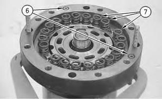
Illustration 3
g00887311
7. Remove O-ring seals (6) . Remove springs (7) .
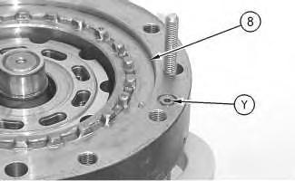
Illustration 4
g00887331
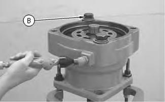
Illustration 5
This is an example of the use of Tooling (B) .
g00890074
8. Place a shop towel over brake piston (8) . Retain brake piston (8) with Tooling (B) . Apply approximately 525 kPa (75 psi) of shop air pressure to brake release Port (Y) . Make sure that the shop air pressure is free of water. Brake piston (8) will move up the piston guide, and out of the piston guide. Remove brake piston (8) from the body of the travel motor.
9. Remove seal (9) and backup ring (10) from the brake piston.
10. Remove seal (11) and backup ring (12) from the brake piston.

Illustration 7
g00887355
11. Remove plates (13) and friction discs (14) .
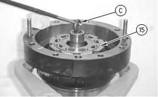
Illustration 8
g00887401
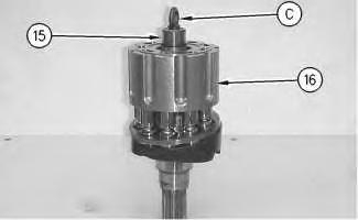
Illustration 9
12. Install Tooling (C) into shaft (15) . Use a prybar to remove the rotating assembly (16) from the housing.
13. Remove Tooling (C) from shaft (15) .
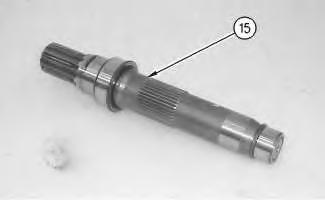
Illustration 10
g00887424
14. Remove shaft (15) from rotating assembly (16) .

Illustration 11 g00887426
15. Use Tooling (D) in order to remove retaining ring (17) from shaft (15) .
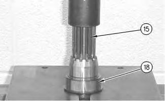
Illustration 12
g00887445
16. Install shaft (15) into a suitable press. Remove bearing race (18) from the shaft.

Illustration 13
g00887463
17. Rotate shaft (15) . Install shaft (15) into a suitable press. Install Tooling (E) . Remove bearing race (19) from shaft (15) .
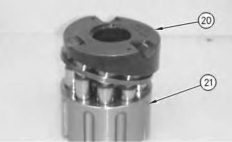
Illustration 14
g00887501
18. Remove cam plate (20) from barrel assembly (21) .
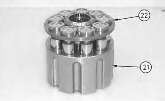
Illustration 15
g00887520
19. Remove piston assemblies and retainer plate (22) from barrel assembly (21) .
Note: Place marks on the pistons and the barrel assembly. The pistons must be returned to the original position.

Illustration 16
20. Remove ball (23) and springs (24) .
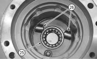
Illustration 17
21. Remove bearing (25) .
g00887578
22. Remove keys (26) and locating pins (not shown) from the body of the travel motor.
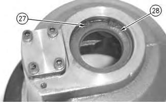
Illustration 18
g00887589
23. Rotate the housing. Use Tooling (F) in order to remove retaining ring (27) .
24. Remove seal (28) .
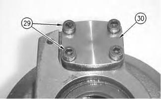
Illustration 19
25. Remove bolts (29) and cover (30) .
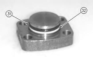
Illustration 20
26. Remove seal (31) and backup ring (32) .

Illustration 21
27. Remove piston actuator (33) and seal (34) .

Illustration 22 g00887762
28. Remove O-ring seal (35) from the housing of the travel motor.
Copyright 1993 - 2020 Caterpillar Inc. All Rights Reserved. Private Network For SIS Licensees.
Thu Jul 16 13:46:07 UTC+0800 2020
Previous Screen
Product: EXCAVATOR
Model: 330D2 EXCAVATOR HSP
Configuration: 330D2 L OEM HSP00001-UP (MACHINE) POWERED BY C7.1 Engine
Disassembly and Assembly
326D2, 329D2 and 330D2 Excavators Machine Systems
Media Number -UENR6134-08
Publication Date -01/09/2018 Date Updated -12/09/2018
Travel Motor - Assemble
SMCS - 4351-016
S/N - DTG1-UP
S/N - EBP1-UP
S/N - EX71-UP
S/N - FEX1-UP
S/N - HSP1-UP
S/N - JFG1-UP
S/N - KER1-UP
S/N - LJE1-UP
Assembly Procedure
Table 1
Required Tools Tool Part Number Part Description Qty A 1P-0510 Driver Gp 1
1. Make sure that all of the components of the travel motor are thoroughly clean and free of dirt and debris prior to assembly.
1
2. Install retaining ring (35) in the groove on shaft (34).
3. Install bearing (36) on shaft (34) with a press. Install the bearing until the bearing contacts the retaining ring.
4. Install the other retaining ring on the opposite side of bearing (36).
2
5. Install inner race (37) on the end of shaft (34) until the inner race is seated against the shoulder on the shaft.

Suggest:
If the above button click is invalid.
Please download this document first, and then click the above link to download the complete manual.
Thank you so much for reading
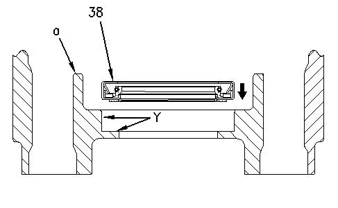
Illustration 3 g00651891 (a) Body
6. Apply a thin coat of 5P-3413 Pipe Sealant on Surfaces (Y) of the body of the travel motor.
7. Use Tooling (A) in order to install lip seal (38).
8. Install lip type seal (38) in the body of the travel motor. Install the lip seal so that the sealing lip is facing in the direction that is shown. Make sure that the lip seal contacts the counterbore in the body of the travel motor.
Note: Slowly rotate shaft assembly (34) during the installation in order to make sure that the shaft assembly does not bind in the body of the travel motor.
9. Apply clean hydraulic oil on the lip of lip seal (38).
10. Use a press to install shaft assembly (34) in the body of the travel motor. Slowly rotate the shaft during the installation in order to make sure that the shaft does not bind. Make sure that the bearing on the shaft contacts the counterbore in the body of the travel motor.
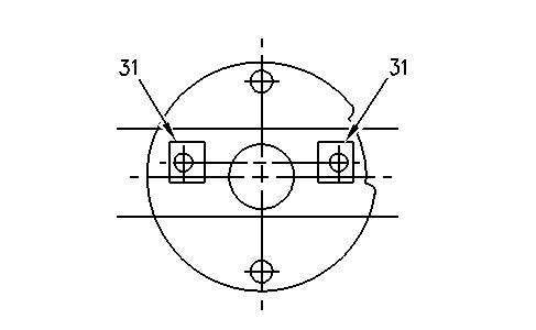
Illustration 4 g00651960
NOTICE
The locating pin on each key is not centered. In order to prevent damage to the barrel assembly during assembly of the travel motor, the keys must be installed as shown. Also, the keys must be installed in the key's original location in the body of the travel motor.
11. Install the two locating pins and two keys (31) in the body of the travel motor, as shown.
Illustration 5
g00510547
12. Install cam plate (30) in the body of the travel motor in the cam plate's original location. Make sure that the two pistons and two keys (31) in the body of the travel motor engage properly with the cam plate.