


ARCHITETTURE
ARCHITETTURE TRASPARENTI
ARCHITETTURE
ARCHITETTURE TRASPARENTI
NINFA STADIO: ISTRUZIONI DI MONTAGGIO (LEGGERE PRIM A DI INIZIARE LA POSA)
Bar positioning
FASCIA MOUNTING ONLY
NINFA STADIO: ISTRUZIONI DI MONTAGGIO (LEGGERE PRIM A DI INIZIARE LA POSA)
NINFA STADIO: ISTRUZIONI DI MONTAGGIO (LEGGERE PRIM A DI INIZIARE LA POSA)
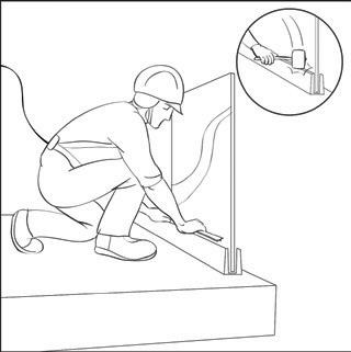
Position the bar, make the first and the last hole.
NINFA STADIO: ISTRUZIONI DI MONTAGGIO (LEGGERE PRIM A DI INIZIARE LA POSA)
Floor drilling
Cleaning
N.B. 2 4 1 3
Attenzione:
Insert two bolts (threaded rods supplied) to keep the profile in position.
Attention:
Attenzione:
- Do not fasten the profile on the sheaths; - Make sure that the fixing is done on solid masonry.
N.B.
Concrete
(Utilizzare punta da 14mm)
(Utilizzare punta da 14mm)
(Utilizzare punta da 14mm)
Attenzione: N.B.(Utilizzare punta da 14mm)
Attenzione: N.B.
Use the drill to mark the position of the holes on the low wall using the already drilled profile as a template. Then move the profile and drill the low wall according to the previously made signs. (Use a 14 mm bit).
Note. The profiles are already drilled according to the class of resistance (300 kg/m - 500 kg/m) required when ordering.
Carefully clean the holes with a suitable pump, or with compressed air, before applying the chemical resin.
Apply certified chemical resin (Fischer V-BOND or similar). Fill the hole about half of its height. Screed
Inserting the rods
Fissaggio profilo a
Fissaggio profilo b

Insert the M12 threaded rods in the holes, leaving the necessary protrusion (24 mm for the internal fastening line, 28 mm for the external) for the profile thickness and the M12 nuts.
Importante:Importante:
Importante: 8 5 6 7
Move the upper adjusters on one side, beyond the size of the glass sheet, to insert the glass avoiding to twist the already assembled external gasket and to have more space for the glass assembly.
Important: once the rod has been inserted into the hole, the resin can overflow. Therefore, carefully clean the excess resin before positioning the aluminium profile.
Corner coupling: solutions on page 7
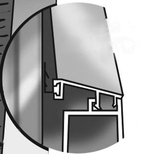
Once the resin has dried, move the profile closer and start fixing. Insert as follows: 1) Rubber washer; 2) Ninfa Stadio profile; 3) Second rubber washer; 4) Galvanized flat washer; 5) M12 nut.
Tighten the nuts very well and then place the transparent polycarbonate glass-holding spacers (3 pieces/meter).
Importante: Importante:
Insert the glass in an inclined position towards the inside, taking care not to touch (twist) the external gasket.
Important: place the glass slowly on the glass-holding spacers (a sudden drop of the glass risks breaking the polycarbonate spacers).
A2 Adjuster
A1 Adjuster
Positioning of the adjusters
Importante:
9.a
9.b
a) Screw the two upper A2 adjusters of the glass sheet (in red), until they come into contact with the glass, ORIENTING THE GLASS SHEET MANUALLY, until the plumb is reached;
b) Screw the lower A1 adjusters of the glass sheet (in blue), constantly checking the level of the bubble;
Important: To tighten the lower A1 adjusters, it is advisable to use a torque wrench with a tightening torque set at 6.5 Nm. FOR A CORRECT FUNCTIONING OF THE SYSTEM, DO NOT TIGHTEN THE A1 AND A2 ADJUSTERS EXCESSIVELY.
Messa in piombo:
Tempered glass sheet
a) Serrare i registri superiori A2 più esterni della lastra (in rosso);
Hardened glass sheet
A1 Adjuster
A2 Adjuster
b) ORIENTANDO LA LASTRA MANUALMENTE , raggiungere il piombo e di conseguenza serrare i registri inferiori A1 più esterni della lastra (in blu), veri cando costantemente il livello della bolla;
c) Completati i primi due passaggi, procedere al serraggio dei registri A1 ed A2 intermedi (in verde);
d) Nell'eventualità che (durante la fase c) il vetro perdesse il piombo, seguire le istruzioni di montaggio al punto 8 per ripristinare il corretto posizionamento della lastra
9.c
N B Per il serraggio dei registri inferiori A1, si consiglia l'uso della chiave dinamometrica con una coppia di serraggio impostata a 6 5Nm
L'ECCESSIVO SERRAGGIO DEI
REGISTRI A1 E A2 PUÒ PORTARE ALL'APERTURA DEL PROFILO E, DI CONSEGUENZA, AL MALFUNZIONAMENTO DEI
REGISTRI STESSI
c) Once the first two steps have been completed, proceed to tighten the intermediate A1 and A2 adjusters (in green);
d) In the event that (during phase c) the glass isn’t plumb anymore, follow the operating instructions of the adjusters in points 10 and 11 to restore the correct positioning of the glass sheet.
Glass alignment with adjusters
IT’S EASY TO ALIGN THE GLASS WITH MILLIMETER PRECISION
13 mm wrench for A2 adjuster
A2 Adjuster
Ratchet (or Screwdriver) for A1 Adjuster
A1 Adjuster
Glass alignment with adjusters
IT’S EASY TO ALIGN THE GLASS WITH MILLIMETER PRECISION
13 mm wrench for A2 adjuster towards the inside towards the inside towards the outside towards the outside
Ratchet (or Screwdriver) for A1 Adjuster
A2 Adjuster
Plumbing and cladding insertion
Glass
A1 Adjuster
When tightening the lower adjuster, the tab of the plastic block may break; it is all normal, the glass blocking system remains well functioning.
Glass
Cladding to be inserted by snap shut
Cladding to be inserted by snap shut
Alignment of the glass towards the outside.
Check with a bubble level if the glass is plumb and then adjust the slope degree of the glass, using the two rows of upper and lower adjusters. To move the glass sheet outwards, loosen the lower A1 adjusters and tighten the upper A2 adjusters. Until the glass is plumb.
Glass alignment towards the inside.
Conversely, to shift the slope of the glass inwards, loosen the upper A2 adjusters and tighten the lower A1 adjusters.
Once the ideal slope degree has been found, tighten the adjusters (we recommend the use of a torque wrench, set the tightening torque to 6.5 Nm).
Cladding inserted
Once the glass is plumb and the adjusters are properly tightened, insert the upper and lower snap-fit cladding.
Inserting caps
Side cap
Screw the side-covering caps with the supplied screws. Evaluate, depending on the case, whether to carry out this operation after point 5.
Finished.
Check again if you properly followed the instructions.
“Bravo!”
(valid for all Ninfa models)
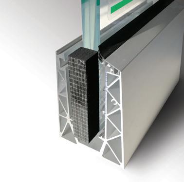
GASKET ASSEMBLY DIAGRAM TO PREVENT WATER INFILTRATION BETWEEN GLASS AND GLASS (VALID FOR ALL NINFA PROFILES)
Cladding to be inserted by snap shut
Note:
Attach the adhesive gasket to the upper
Gaskets included in the supply.
Important: Align the gasket with the reference line.
The adhesive gasket that you find in the package is supplied with the suitable height and glass thickness for that type of Ninfa model. Place the adhesive gasket on the glass after having inserted it in the profile, then follow the assembly instructions starting from point 8.
Seal at the beginning and at end after inserting the cap
Ninfa profile cap
After placing the 1st glass, repeat the same assembly sequences with the next glass, taking care to push the 2nd glass against the gasket until it is compressed by about 1mm.
Sealing: use only neutral black silicone.
Once all the glass has been positioned, seal well between glass and glass and on the gasket before inserting the internal snap-fit cladding.
BRACKETS FOR COUPLING CORNERS
Assembly
ACCESSORY FOR LINEAR JOINTS BETWEEN THE BARS
Assembly without drilling the profile. (Valid for all Ninfa models). PROFILE
Accessory to be ordered separately.
Accessory to be ordered separately.
Accessory to be ordered separately.
Tighten the nuts very well and then place as follows:
1) Aluminium LED-holding profiles in pieces (3 pieces/meter); 2) LED-holding profile in continuous aluminium;
3) LED strip; 4) Snap-fit polycarbonate profile.
Once the LED system have been installed, follow the assembly instructions continuing from point 5.
The glass will
ARCHITETTURE TRASPARENTI
ARCHITETTURE TRASPARENTI
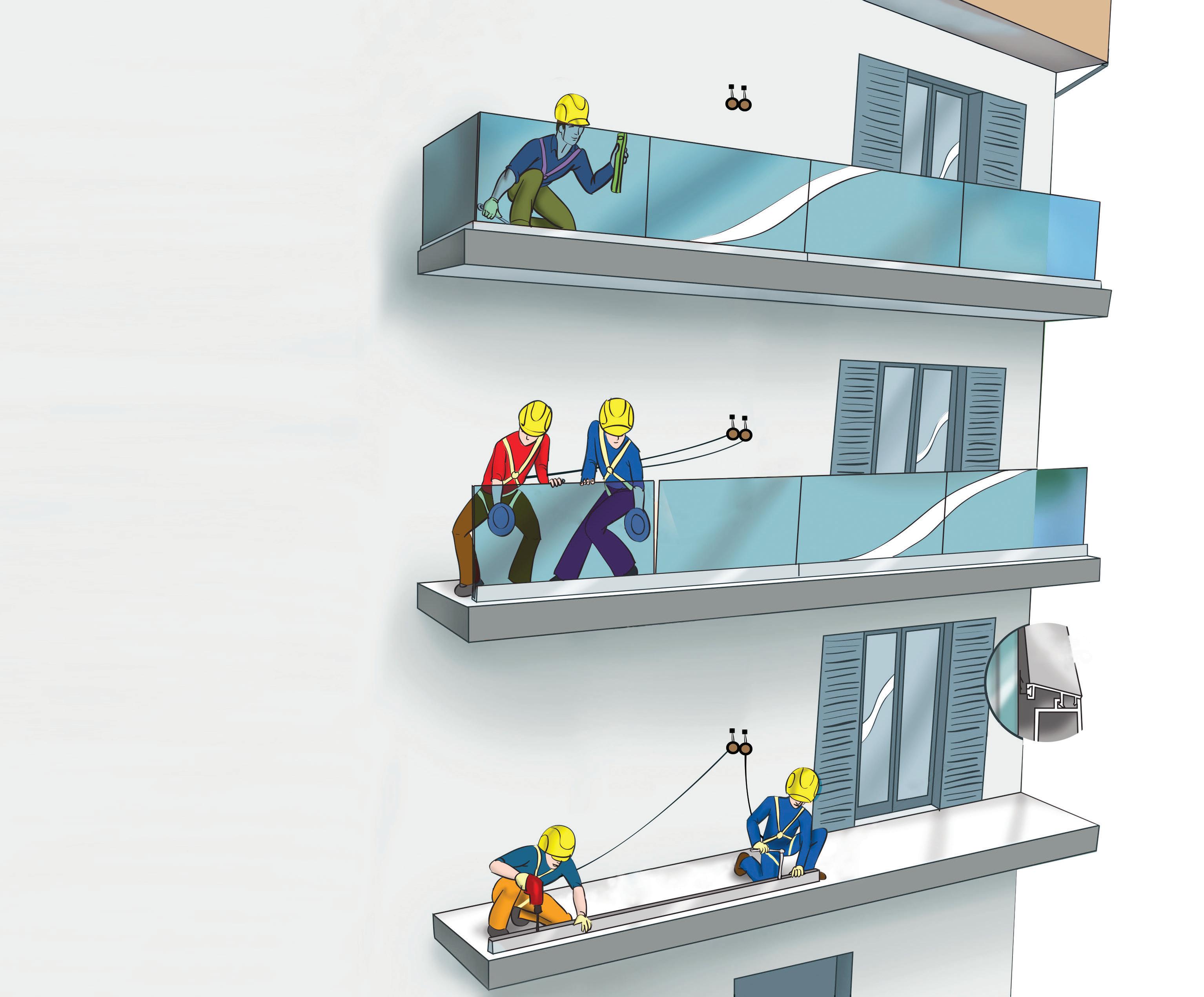
Illustrations: example of glass assembly.
• No scaffolding or external platforms required.
• Glass mounting only from the inside.
• Adjustable to plumb the glass by acting only from the inside.
• Work in safety.
MAXIMUM ATTENTION TO SAFETY
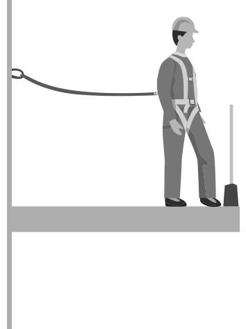
FALL PROTECTION SYSTEM WITH FASTENING ON A SOLID ANCHORAGE POINT
Note:
Follow the Safety Manager’s instructions on site.
ARCHITETTURE TRASPARENTI
FARAONE SRL
ARCHITETTURE TRASPARENTI
SEDE via Po 12 - 64018 Tortoreto Lido (TE)
T 0861 784200
F 0861 781035 @ faraone@araone.it WEB www.faraone.it
ADJUSTMENT AND PLUMBING
FLOOR DRILLING AND FIXING OF THE ALUMINIUM PROFILE