TURBIDITE SYSTEMS: AN OUTCROP-BASED ANALYSIS
Emiliano Mutti
On the cover
Emiliano Mutti.
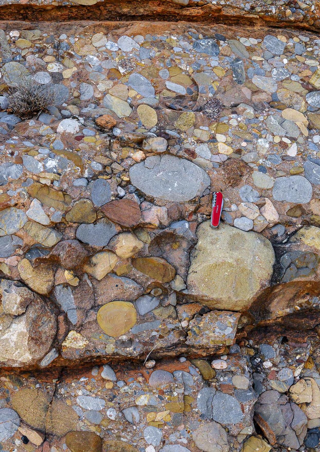
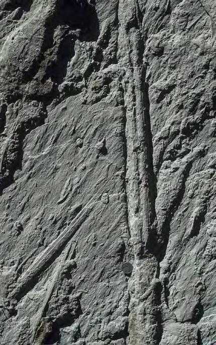
Graded, clast-supported conglomerate division comprising almost the entire thickness of the flood unit. Oligocene Ebro Basin, south central Pyrenees.
Designed by María Julia Gouffier - Firjan-Senai
First published in 2023
M993t Mutti, Emiliano
Turbidite systems : an outcrop-based analysis / Emiliano Mutti. – 1. ed. – Rio de Janeiro : PETROBRAS, 2023.
466 p. : il. color. ; PDF.
Inclui referências.
ISBN: 978-65-88763-05-6
1. Turbidito. 2. Sedimentos marinhos. 3. Sedimentação e depósitos.
I. Título.
CDD 551.46
EMILIANO MUTTI
Professor Mutti, who likes to be considered primarily as a field geologist, has mainly worked on stratigraphy and sedimentology of deep-water turbidite basins in a variety of geodynamic settings worldwide. He devoted particular attention to the study of the exposed Tertiary foreland basins of the northern Apennines, the Spanish Pyrenees and the island of Rhodes (Greece). His work on turbidites is summarized in classical papers he wrote with Franco Ricci Lucchi and William R. Normark. These papers are among the most widely cited in the literature.
Since the late 80’s, he has also become interested in flood-dominated fluvio-deltaic sedimentation and its relations to that of turbidite systems, as well as in contourite and contourite-turbidite systems.
As a consultant, he has worked for many major oil company on training programs and exploration problems in Europe, Brazil, Argentina, Africa and Indonesia. Last, but not least, Professor Mutti has been a highly respected teacher and supervisor for a long list of students.
emiliano.mutti@unipr.it

Education
1971 - Libera Docenza (Ph D equivalent), University of Turin
1959 - M. Sc., University of Milan
Academic and professional experience
2008 - Present: retired Professor
2007 - Retired from the University of Parma
1982-2007 - Full Professor of Sedimentary Geology, University of Parma (Italy)
1969-1982 - Assistant, Associate, and Full Professor of Sedimentology, University of Turin (Italy)
1965-1969 - Research Geologist, Esso Production Research (EPRco), European Laboratories, Bordeaux (France)
1960-1965 - Assistant Professor of Sedimentology, University of Milan (Italy)
Selected Honors and Awards
2016 - ENI Award
2012 – EGU (European Union of Geosciences) Lamarck Medal for “his internationally acclaimed research in clastic sedimentology, especially his ground-breaking detailed field-based models of turbidite systems, their petroleum reservoir characterization, and their relationship to fluvio-deltaic systems.” (the highest award of the Union)
2011 – Honorary fellow of the Italian Geological Society
2004 - SEPM (Society for Sedimentary Geology) Twenhofel Medal for “outstanding contributions to Sedimentary Geology” (the highest award of the Society)
2003 - EAGE (European Association of Geoscientists & Engineers) Wegener Medal (Award for Outstanding Contribution) “for his worldwide contribution to sedimentary dynamics of turbidites and their reservoir characterization during the last half century. His pioneering work has had a significant impact on petroleum geosciences. His broad international outlook and his attachment to the human values and “natural“ geology are highly appreciated by all communities who have worked jointly with him” (the most prestigious award made by the Union)
1996 - Distinguished lecturer of IAS (International Association of Sedimentologists) on “Fluviodeltaic and turbidite sedimentation” (North America, Europe, South Africa and Asia)
1996 - Distinguished lecturer of AAPG on “Turbidite systems and their relations to catastrophic fluvial sedimentation” (Latin America)
1993 - Honorary fellow of the Geological Society of London
1992 - Miembro correspondiente of the Asociación Geológica Argentina
1984/1985 - Distinguished lecturer of AAPG on “Turbidite systems” (North America)
IV.5
IV.5.1
IV.5.2
TURBIDITE SYSTEMS: AN OUTCROP-BASED ANALYSIS SUMMARY PRESENTATION ............................................................................................................... 8 PREFACE ............................................................... ............................................................ 9 ACKNOWLEDGEMENTS ............................................................... ................................. 14 CHAPTER I: GENERAL CONCEPTS ............................................................... ............... 15 I - INTRODUCTION....................................................................................................................................................15 I.1 - The beauty of rocks.....................................................................................................................................15 I.2 - Layering and beds.......................................................................................................................................29 II - STRATIGRAPHIC UNITS, THEIR BOUNDING SURFACES AND BASIC PRINCIPLES OF SEQUENCE STRATIGRAPHY......................................................................................32 III - TRANSGRESSIONS, REGRESSIONS AND UNCONFORMITIES.......................................................................40 IV - A SIMPLE APPROACH TO INFORMALLY SUBDIVIDE STRATIGRAPHIC SUCCESSIONS...............................44 IV.1 - Depositional units and their hierarchy...................................................................................................44 IV.2 - Small-scale units........................................................................................................................................47 IV.2.1 - Types of bed..................................................................................................................................47 IV.2.2 - Bed thickness and geometry.......................................................................................................53 IV.2.3 - Types of bed accretion.................................................................................................................58 IV.3 - Medium-scale units...................................................................................................................................62 IV.3.1 - General...........................................................................................................................................62 IV.3.2 - Definition of facies........................................................................................................................63 IV.3.3 - Sedimentological facies...............................................................................................................65 IV.3.4 - Facies sequences and facies associations.................................................................................65 IV.3.5 - Facies and environment of deposition.......................................................................................67 IV.3.6 - Time-parallel and time-transgressive facies boundaries.......................................................67 IV.3.7 - Sedimentological facies and stratigraphy.................................................................................67 IV.3.8 - Lithofacies, lithofacies sequences and lithofacies associations............................................75
- Large-scale units.......................................................................................................................................81
IV.4
- A pragmatic and informal sequence-stratigraphic approach..............................................................81
- General...........................................................................................................................................81
- Elementary depositional sequences (edss), equilibrium point and the problem of parasequences.........................................................................................................82
- The importance of EDSs..............................................................................................90 IV.5.2.2 - EDSs, short-lived and long-lived depositional systems (and elements)..............94
IV.5.2.1
I
II
III
I.1 - General........................................................................................................................................................100
I.2 - The birth of turbidites and their golden age.........................................................................................102
I.3 - The “flowing grain layer” of Sanders (1965)..........................................................................................103
II.1 - The suprafan model of Normark (1970)................................................................................................104
II.2 - The canyon-fed model of Mutti and Ricci Lucchi (1972).....................................................................105
II.3 - Fan model with detached lobes (Mutti and Ricci Lucchi, 1974)..........................................................106
II.4 - The composite deep-sea fan model of Walker (1978).........................................................................109
II.5 - Delta-fed models implying multiple channels (Chan and Dott, 1983; Heller and Dickinson, 1985)......................................................................................109 II.6 - The highly and poorly efficient fan systems of Mutti (1979).............................................................111 II.7 - The complexity of deep-sea fans as reviewed by Richard and Reading (1994)...............................112
III.1 - The advent of seismic and sequence stratigraphy and its impact on
IV
TURBIDITE SYSTEMS: AN OUTCROP-BASED ANALYSIS CHAPTER II: TURBIDITES ............................................................... ............................ 100
– TURBIDITES:
BRIEF HISTORICAL REVIEW OF SELECTED PREVIOUS WORK..............................................100
MODELS....................................................................................................................................103
- DEEP-SEA FAN
- ACADEMY AND INDUSTRY..............................................................................................................................112
turbidite sedimentation....................................................................................................113
- FURTHER DEVELOPMENTS..............................................................................................................................115 V - SOME CONCLUDING REMARKS........................................................................................................................126 VI - WHAT CAN BE LEARNT FROM EXPOSED TURBIDITE SYSTEMS OF FORELAND BASINS........................126 VI.1 - General....................................................................................................................................................126 VI.2 - Foreland basin types.............................................................................................................................127 VI.3 - Main characteristics of foreland basin turbidite sedimentation.................................................128 VI.4 - Turbidite systems and their component stages and elements.......................................................131 VI.4.1 - Definitions and general schemes..........................................................................................131 VI.4.2 - Slope sediments......................................................................................................................133 VI.4.3 - Turbidite elements...................................................................................................................139 VI.4.4 - A concluding remark................................................................................................................158 VII – TURBIDITE FACIES..........................................................................................................................................159 VII.1 - Introduction.........................................................................................................................................159 VII.2 - Selected previous work.......................................................................................................................159 VII.3 - Some remarks on turbidite facies analysis.......................................................................................168 VII.4 - The rationale behind new attempts..................................................................................................169 VII.5 - Descriptive and genetic turbidite facies...........................................................................................169 VII.6 - The facies tract concept.....................................................................................................................170 VII.7 - The channel-lobe transition zone and its problems.........................................................................176 VII.8 - A suggested new classification..........................................................................................................176 VII.8.1 - Introduction and basic subdivisions...................................................................................177 VII.8.1.1 - Tectonic mélanges and large-scale mass transport deposits (slumps, slides, blocky flows)...............................................................................................179 VII. 8.1.2 - F1 and its facies boxes........................................................................................183 VII. 8.1.3 - F2 and its facies boxes........................................................................................190
III
VII. 8.1.4 - F3 and its facies boxes........................................................................................213
VII. 8.1.5 - F4 and its facies boxes........................................................................................223
VII. 8.1.6 - F5 and its facies boxes........................................................................................235
VII. 8.1.7 - F6 and its facies boxes........................................................................................244
VII.
IV.4 - The problem of flow criticality............................................................................................................278
V - A TURNING POINT: ACTIVE MARGIN SEDIMENTATION AND THE IMPORTANCE OF “DIRTY RIVERS” IN
VI - ANCIENT FLOOD-DOMINATED FLUVIO-DELTAIC SYSTEMS OF OROGENIC BELT BASINS AND THE ROLE OF HYPERPYCNAL FLOWS.........................................................290
VII - WHAT DO WE REALLY KNOW ABOUT HYPERPYCNAL FLOWS?................................................................292
VII.1 - Hyperpycnal flows and their deposits..............................................................................................292
VIII.2 -
VIII.3 - The basic types of flood-dominated alluvial and fluvio-deltaic systems................................319
TURBIDITE SYSTEMS: AN OUTCROP-BASED ANALYSIS
CHAPTER III ............................................................... .................................................. 256 CHAPTER IIIA (FLOOD-DOMINATED FLUVIO-DELTAIC SYSTEMS)....................................................................256 I - A PREMISE...........................................................................................................................................................256 II - INTRODUCTION TO FLOOD-DOMINATED ALLUVIAL
FLUVIO-DELTAIC SYSTEMS...........................256
8.1.8 - A final note on hydraulic jump-related deposits............................................251
AND
- NORMAL VS EPISODIC SEDIMENTATION.......................................................................................................258
- FLUVIO-DELTAIC SYSTEMS: GENERAL CHARACTERISTICS........................................................................261 IV.1 - The basic conceptual model................................................................................................................261 IV.2 - Some basic relationships between flow velocity and depth, grain size, and bedforms................268 IV.2.1 - Bedload structures..................................................................................................................268 IV.2.2 - Suspended load structures....................................................................................................275 IV.3 - Some remarks on trough cross-bedding, sigmoidal
sigmoidal bars.....................276
IV
bedding, and
DELTA
FORMATION..........................................................................................................287
VII.2 - Turbidites, hyperpycnites and plumites..........................................................................................302
main
and inferred processes...............................................................................................................306 VII.4
Flow
dunes”..............................................................................315
- MAIN TYPES
FLOOD-DOMINATED
FACIES ..........................................317
- Introduction.......................................................................................................................................317
VII.3 - The importance of flood-generated sigmoidal cross-bedding:
types
-
regime variations and “humpback
VIII
OF
SYSTEMS, ELEMENTS, AND
VIII.1
Terminology
problems......................................................................................................................318
The
Flood-dominated
VIII.3.1 - Alluvial fans and their terminal flood basins................................................................319 VIII.3.1.1 -
importance of terminal flood basins....................................................320 VIII.3.1.2 -
alluvial fans.....................................................................323
VIII.3.1.3 - Some concluding remarks.............................................................................329
VIII.3.2 - River deposits....................................................................................................................335
VIII.3.2.1 - Flood-dominated laterally accreting deposits...........................................336
VIII.3.2.2 - Flood-dominated vertically and downstream accreting deposits
VIII.3.2.2.1 - Gravelly river element..............................................................341
VIII.3.2.2.2 - Sandy river elements...............................................................346
VIII.3.3 - Delta front and prodelta elements................................................................................357
VIII.3.3.1 - General............................................................................................................357
VIII.3.3.2 - Channel-exit deposits....................................................................................358
VIII.3.3.2.1 - Channel-exit deposits of river deltas systems.....................359
VIII.3.3.2.2 - Channel-exit deposit of fan delta systems...........................364
VIII.3.3.2.2.1 - Transient wave action reworking..................................370
VIII.3.3.3 - The sandstone lobe element........................................................................372
VIII.3.3.4 - The prodelta element....................................................................................395
VIII.3.4 - Reworking by tides and waves..........................................................................................396
TURBIDITE SYSTEMS: AN OUTCROP-BASED ANALYSIS
..........340
CHAPTER IIIB (CONCLUSIONS AND SOME PERSONAL THOUGHTS)................................................................414 I - THE IMPORTANCE OF FACIES AND FACIES ASSOCIATIONS...........................................................................414 II - SEQUENCE STRATIGRAPHY AND ITS APPLICATION TO FOLD AND THRUST BELT BASINS....................416 III - FLUVIAL FLOODS AND TURBIDITY CURRENTS............................................................................................427 IV - A MINOR BUT IMPORTANT REFINEMENT OF TURBIDITE FACIES SCHEMES............................................428 IV.1 - The importance of coherence in dense flow evolution.....................................................................428 V - TURBIDITES AND CONTOURITES....................................................................................................................431 VI - OROGENIC BELT AND CONTINENTAL MARGIN BASINS...............................................................................441 VII - ARTIFICIAL INTELLIGENCE AND QUALITY OF GEOLOGICAL INPUT DATA..............................................442 VIII - THE FUTURE OF SEDIMENTARY GEOLOGY................................................................................................443 REFERENCES 446
PRESENTATION
Petrobras is honored to deliver to the Geosciences community the book entitled Turbidite Systems: An Outcrop-Based Analysis authored by Professor Dr. Emiliano Mutti. The present edition contains part of his Work, the fruit of his exemplary dedication to scientific work, developed over several decades in the field, in classrooms of the most renowned teaching institutions in the world, and together with major international oil companies, including Petrobras.
Professor Dr. Emiliano Mutti, recognized and awarded several international awards, is the author of dozens of scientific articles and several books, having based his academic life on the study of the stratigraphy and sedimentology of sedimentary basins tectonically exposed in orogenic belts, especially in the Spanish Pyrenees and the northern Italians Apennines.
With the advance of the oil discoveries in turbidite reservoirs in the Campos Basin, in the 1970s and 1980s, the deepening in the knowledge of this type of reservoir became imperative and Professor Mutti, with his brilliance and innovative ideas, became part of the history of oil exploration at Petrobras.
In addition to his invaluable contribution to the construction of the basis for modern sedimentary facies analysis, the basic cell of Sedimentology and Modern Stratigraphy, Professor Emiliano Mutti has acted as consultant and actively collaborated in the training, qualification and post-graduation projects of Petrobras’ geoscientists. Since the 2000s, this action has intensified with the resumption of field courses by our explorers in the Spanish Pyrenees and the northern Apennines in Italy.
Turbidite Systems: An Outcrop-Based Analysis represents an outstanding scientific contribution to current and future generations of scholars in the Earth Sciences and in particular Petroleum Geology.
We register our recognition for the incomparable work of Professor Mutti and our gratitude for his willingness to share his knowledge, such as that registered in this book, which we are privileged to be able to edit as a chapter of his Work.
Welcome to this adventure of knowledge and enjoy your reading.
8 TURBIDITE SYSTEMS: AN OUTCROP-BASED ANALYSIS
PREFACE
In the late 80’s, after spending many years studying turbidites of orogenic belt basins, I started to realize that I was missing an important part of the history of these basins, i.e., the relationships between turbidite systems and their adjacent shallow-marine and alluvial feeder systems.
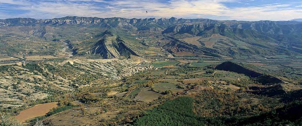
So, I decided to start climbing the slope of the Eocene Hecho Group deep-water basin in the south-central Pyrenees – the basin I knew best – leaving behind my beloved turbidites. After a few months I was totally immersed in the study of the eastern margin of the deep-water turbidite basin, the magnificent Tremp-Graus basin (Figure 1) with its alluvial, fluvio-deltaic and shelfal deposits coeval with the Hecho Group turbidites.
The long journey from the deep basin to its alluvial equivalents has been one of the most interesting and rewarding experiences of my professional life. After a while and to my great surprise, I came to the conclusion that most of the beds that I was observing day after day had basic similarities to the turbidite beds I was familiar with in that they were also sharp-based, overall graded and displaying vertically ordered laminated divisions. Also, to my great surprise, I gradually realized that my observations were casting increasingly serious doubts on what I had learnt from the literature on fluvial and deltaic systems.
At this point, I thought it was necessary to re-examine many outcrops that I had seen before and this made me visit or revisit more carefully the Neuquén and San Jorge basins, Argentina, the Tertiary Piedmont Basin, NW Italy, the Pleistocene Sant’Arcangelo Basin and the Tertiary Calabrian Basin, southern Italy, as well as in many other basins in Brazil, Greece and Spain.
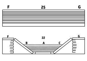
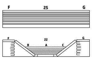
As a result of these new observations, I became definitively convinced that graded beds form a dominant component of both alluvial and shallow-marine terrigenous successions and that these beds, which can only be interpreted as the deposit of sediment gravity flows, share many characteristics with deep-water turbidites. The simple conclusion that at this point must be drawn for the principle of parsimony is that, for an increasing degree of energy, episodic fluvial floods may generate catastrophic or convulsive events that enter floodplain, lacustrine or marine basins as sediment gravity flows moving for their excess density (hyperpycnal flows of Bates, 1953) and carrying their sediment load in progressively more basinal zones. These episodic flows periodically increase their frequency for cyclic climate variations, thus becoming almost “uniformitarian” during certain periods of time when large amounts of water are made available in drainage basins and being responsible for impressive accumulations of turbidite and fluvio-deltaic sands. As suggested in a previous and preliminary work (Mutti et al., 1996), the ultimate consequence of this hypothesis are systems that go directly from a river flood to the final accumulation of deep-water turbidite sands, as in the well-known example of the Missoula flood (see Zuffa et al., 2000). Perhaps in a somewhat provocative way, these systems were referred to as “fluvio-turbidite systems” by Mutti et al. (1996) (Figure 2).
Of course, I am fully aware that turbidity currents can be triggered by causes other than rivers in flood (see Normark and Piper, 1991; Piper and Normark, 2001, for a thorough discussion). However, as amply discussed in this book, there are several criteria that permit to distinguish delta-fed systems from turbidite deposits generated by highly catastrophic events associated with earthquakes, tsunami, basin margin collapses and similar high-magnitude and low-frequency events.
When I presented some of the results of my observations and related preliminary conclusions in a workshop in Oxford (Mutti, 1992a), I soon became aware that either my observations and conclusions were completely wrong, or they were seriously conflicting with some different points of view. The differences, as I clearly realized, were essentially two: (1) my “catastrophic” approach to the problem, in disagreement with the rather “uniformitarian” approach, though with some caution, of the school of thought that was at that time dominating sedimentological research worldwide, and (2) my interpretation of HCS that for the Walther’s law (vertical and lateral stratigraphic relationships) I was forced to relate with floods entering a body of water rather than with wave storm-dominated environments. Both arguments are amply discussed later.
9 TURBIDITE SYSTEMS: AN OUTCROP-BASED ANALYSIS
10 TURBIDITE SYSTEMS: AN OUTCROP-BASED ANALYSIS
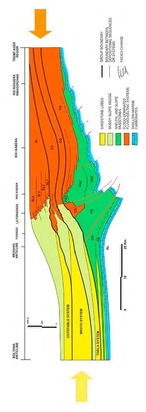
Fig. 1Stratigraphic cross-section of the Eocene foreland basin of the S-central Pyrenees showing the relationship between basinal turbidites and fluvio-deltaic strata (from Mutti et al., 1988).
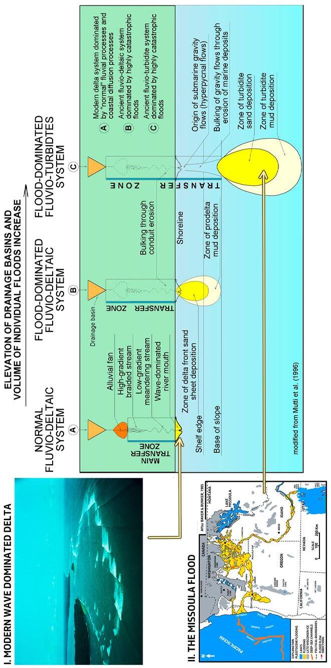
2Fluvio-turbidite systems form when highly catastrophic floods carry sediment directly from drainage fluvial basins to deep waters, eroding alluvial and nearshore staging areas. Note how transfer zones and staging areas vary during the evolution from A to C.
11 TURBIDITE SYSTEMS: AN OUTCROP-BASED ANALYSIS
Fig.
Nonetheless, much of the results of the research I carried out with my co-workers were published in several articles (Mutti et al., 1996, 2003a, 2003b, 2009) and presented orally on occasion of many meetings and invited lectures (AAPG distinguished lecturer, Central and South America, 1996; IAS special lecturer, Europe, North America, Africa and Indonesia, 1996; invited lectures at AAPG Meeting, Long Beach, 2007; AAPG Meeting, Milan. 2011; EAGE meeting, Vienna 2013 among others).
This book summarizes many of the field observations of 25 years and attempts a few general conclusions that can be drawn from these observations. Most of my field work has always been based on careful examination of beds, their geometry, texture and internal structure and on the attempt to frame these beds within their local and regional stratigraphic, structural and depositional context. The approach is very time-consuming, but I have been fortunate in my life since as a professor I could always find time and funds for long field seasons alone or, most commonly, with my students and many colleagues. There are thousands of beds that I would say I know “personally”, and I have thousands of photographs that will remind me these beds even when I will not be able to go to the field any longer. Clearly, the book relies very heavily on my personal experience, thus being biased by what I have seen and studied over the years, an inherent limitation shared by most of us, though.
The assumption behind this book is that in tectonically active basins, fluvio-deltaic and deep-water turbidite systems are in most cases the shallow-water and the deep-water expression, respectively, of a series of processes that are essentially originated by rivers in flood and ultimately by climate variations and the tectonic setting. The “dirty rivers” of Milliman and Syvitski (1992), associated with high-elevation drainage basins, steep gradients, and narrow alluvial plains provide a simple and convincing way of thinking to partly understand active margin sedimentation and the relationships between turbidites and fluvial systems, a problem of paramount importance for basin analysis in orogenic belts and probably in other settings. Huge accumulations of flood-generated delta-front sands, that could be termed shallow-water turbidites, are a new and very interesting target for hydrocarbon exploration. As discussed later, this implies that climate and sediment flux to the sea are basic controlling factors also in the development of sequence stratigraphic interpretation.
The book describes and discusses beds, facies and facies associations of sediment gravity flow-dominated depositional systems that are observed in the settings above, believing that they are of primary importance in the study of most ancient basins because of their volumetric importance and their obvious bearing on hydrocarbon exploration and production. Since, if taken in isolation, beds and facies may be often misleading, a first chapter extensively reviews some basic principles of physical stratigraphy and facies analysis, as well as approach and terminology adopted herein. In particular, facies, facies associations, lithofacies and elementary depositional sequences, where the analysis of individual beds plays a critical role, are reviewed and discussed in detail. Most of the examples and concepts derive from my field work in the Eocene of the Pyrenees and deal principally with marginal marine sediments which are the most suitable for an understanding of the basic principles of stratigraphy and facies analysis. Transferring the same principles to the study of deep-water successions remains difficult at present for obvious reasons, though it is clear that a similar way of thinking should be followed also for these sediments. The problem is dealt with in the second chapter.
I think that the life of every geologist is marked by a primary geological interest in one problem. No doubt, my primary interest has been that of understanding the magnificent foreland basin of the south-central Pyrenees between the late Cretaceous and the end of the Eocene. I have been working there since 1966, when I was a young research geologist of Esso Production Research. In 1969 I resigned from Esso (where I learnt much) and moved back to university. Ever since, the Pyrenees remained my primary interest and I can say that I spent there a substantial part of my life. My work is essentially summarized in two guidebooks prepared for an AAPG meeting held in Barcelona in 1988 and for the “Second high-resolution sequence stratigraphy conference” convened by Henry W. Posamentier and Emiliano Mutti which was held in Tremp, Spain, in 1994 (Mutti et al., 1988; Mutti et al., 1994) and not in formal publications. The reason is simple: a guidebook discusses work in progress, with its doubts and problems, whereas in a formal paper on a prestigious journal you are supposed to convince the reader that you came to a conclusion. The geology of the Pyrenees is very well exposed, and this is probably the reason why is so elusive. Instead of coming to a conclusion with time (and certainly I spent many years out there), I rather multiplied the number of problems which were raising almost every day. I passed through alternating periods of enthusiasm and pessimism and thus gradually became aware that geology had to be that way and I liked it so. I thus became rather skeptical about models and fancy interpretations that often hide what the real world is. Models may be useful shortcuts for a while, though short living in the long term.
12 TURBIDITE SYSTEMS: AN OUTCROP-BASED ANALYSIS
Of course, I love sedimentology, but despite what some people may think, I always used sedimentology mainly as a tool to better understand geology. And geology, at least in my opinion, starts and ends with maps and cross-sections. My basic background comes from having mapped in detail a substantial part of the island of Rhodes, Greece, between 1961-1965 (Mutti et al., 1969, 1970), the Eocene of the south-central Pyrenees (Mutti et al., 1988), and to a lesser degree the Tertiary Piedmont Basin, northwestern Italy (Mutti et al., 1995, 2002). Most of the rocks I mapped were turbidites, so I had to become familiar with them and try to understand their geological meaning. With time, I became obviously very interested in their sedimentological aspects. The same happened later with the fluvio-deltaic sediments of the Pyrenees.
I greatly benefited from my work as a consultant that allowed me to visit many outcrops and examine kilometers of cores from many basins worldwide, discuss basic problems of exploration and production with so many explorationists, and become familiar with seismic data which have certainly revolutioned our way of approaching basin analysis and reservoir geology.
I tried to keep the text as much informal as possible, having in mind that the potential readers would be mostly young researchers who would appreciate some fresh air and simple writing. The many figures and photographs should be hopefully self-explanatory in most cases. Some figures are sketches I prepared for my students directly in the field. Bibliographic references are limited to really important and pertinent papers and books. Exceptions are made for some historical reviews and some problems which are particularly debated, thus requiring being aware of alternative interpretations.
13
SYSTEMS:
TURBIDITE
AN OUTCROP-BASED ANALYSIS
ACKNOWLEDGEMENTS
Writing a book at an advanced age at the end of a very long academic and professional career was no simple undertaking. Above all, I wondered whether it was worthwhile, given how geology has changed in the last decades from the old naturalistic approach (to which I feel I belong) to an ever more complex and integrated multidisciplinary form. Mario Carminatti, who was my student at the University of Parma, finally convinced me it was worth the effort because my experience would be useful to younger geologists. I am very much indebted to him for making this project possible. I must also thank my wife Edda for her patience and support as I carried out this long task.
During my life I have met thousands of geologists and geology students with whom I have interacted when studying outcrops, cores, geologic maps and seismic lines, and discussing various aspects of sedimentary geology. Much of what I have learned comes directly or indirectly from them. It would be impossible to acknowledge them all here individually. I will therefore limit myself to thanking a restricted number of people from Petrobras who have had a great influence on this book.
In particular, I would like to mention: Roberto d’Ávila, Saulo Ferreira Santos, Pierre Muzzi Magalhaes, Kayo Delorenzo Nardi Dias and Luci Arienti, who were my colleagues on truly memorable field trips in Brazil, Argentina, Spain and Italy; Lincoln Rumenos Guardado and Mozart Cavalcante de Barros, with whom, at the beginning of my collaboration with Petrobras, I was excited to recognize the first contourites in the Eocene of Campos Basin; and Rogério Soares Cunha and Fabrizio Dias Lima, who accompanied me in perfoming a critical reexamination of many classical outcrops of turbidites and delta deposits during many months of field work in Spain and Italy in 2016-2017.
Finally, I would like to thank Roberto D’Ávila and Maria Luiza Martini for the help they gave me during the first phase of editing, and Rogério Soares Cunha for the final supervision of the project.
This book is dedicated to the memory of my grandfather Domenico Mutti who, in the second half of the 19th century, spent 20 years in Brazil working as a traveling salesman (mascate) in the remote Mato Grosso. With his hard work he managed to earn enough to allow my father Ido to study when he returned to Italy, and I, in my turn, was able to study and become a geologist. Thus, my attachment to the wonderful land of Brazil runs deep.
14 TURBIDITE SYSTEMS: AN OUTCROP-BASED ANALYSIS
CHAPTER I: GENERAL CONCEPTS
I - INTRODUCTION
I.1 - THE BEAUTY OF ROCKS
Trying to understand sedimentary rocks is not as simple as one might think after being reassured by reading many recent papers and textbooks on sedimentology, stratigraphy and facies analysis. Over 50 years of experience have convinced me that one has to look at the rocks the way they are and not the way they may fit one’s preconceived ideas or existing models. I personally believe that either you love sedimentary rocks, or it may be difficult to get some serious answers from them. Loving them means that
you are fascinated by their layering, colour and grain size variations, internal depositional structures, their fossil content, sole markings and, at least for me, by the sense of deep mystery they emanate. Though not discussed in this book, a similar beauty can be appreciated when sedimentary rocks are observed in thin section under the microscope. Some examples of this beauty are shown in Plates 1- 13, with emphasis on sole markings, which are also fundamental for the information they can give on paleocurrent directions. The interested reader is referred to a masterpiece on this subject written by Dzulinsky and Sanders (1962), two pioneers of modern sedimentology. I loved these structures very much when I started observing sedimentological features.
CHAPTER I: General concepts TURBIDITE SYSTEMS: AN OUTCROP-BASED ANALYSIS 15
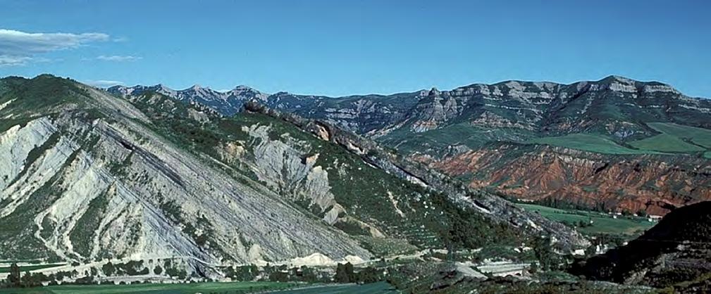
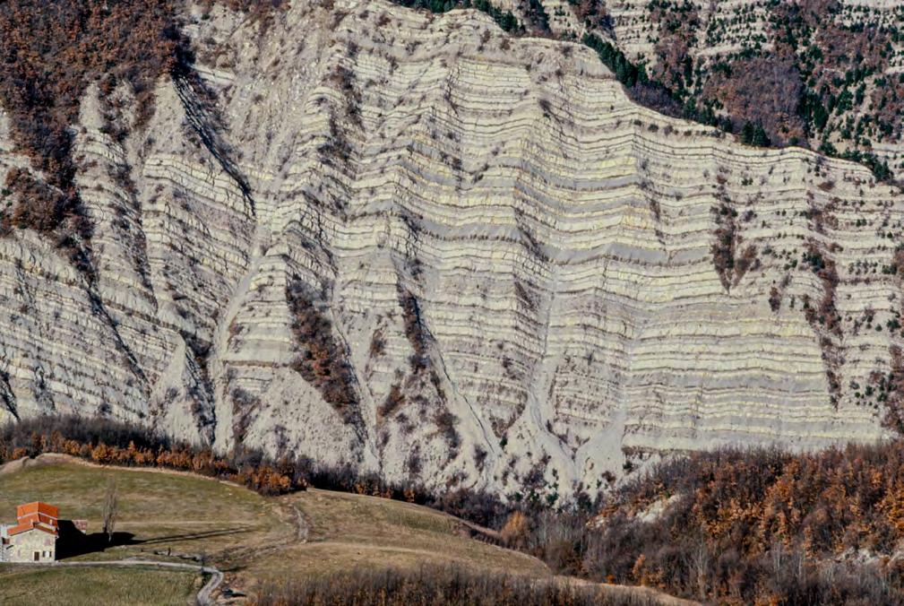
Plate 1 - Spectacular exposure of upper Cretaceous and Tertiary sediments in the Riba Gorzana Valley, south-central Pyrenees. In the background the virtually flat-lying upper Eocene and Oligocene conglomerates resting unconformably on folded and faulted strata deformed at the end of late Middle Eocene. This geological setting is further expanded in the concluding chapter.
CHAPTER I: General concepts TURBIDITE SYSTEMS: AN OUTCROP-BASED ANALYSIS 16
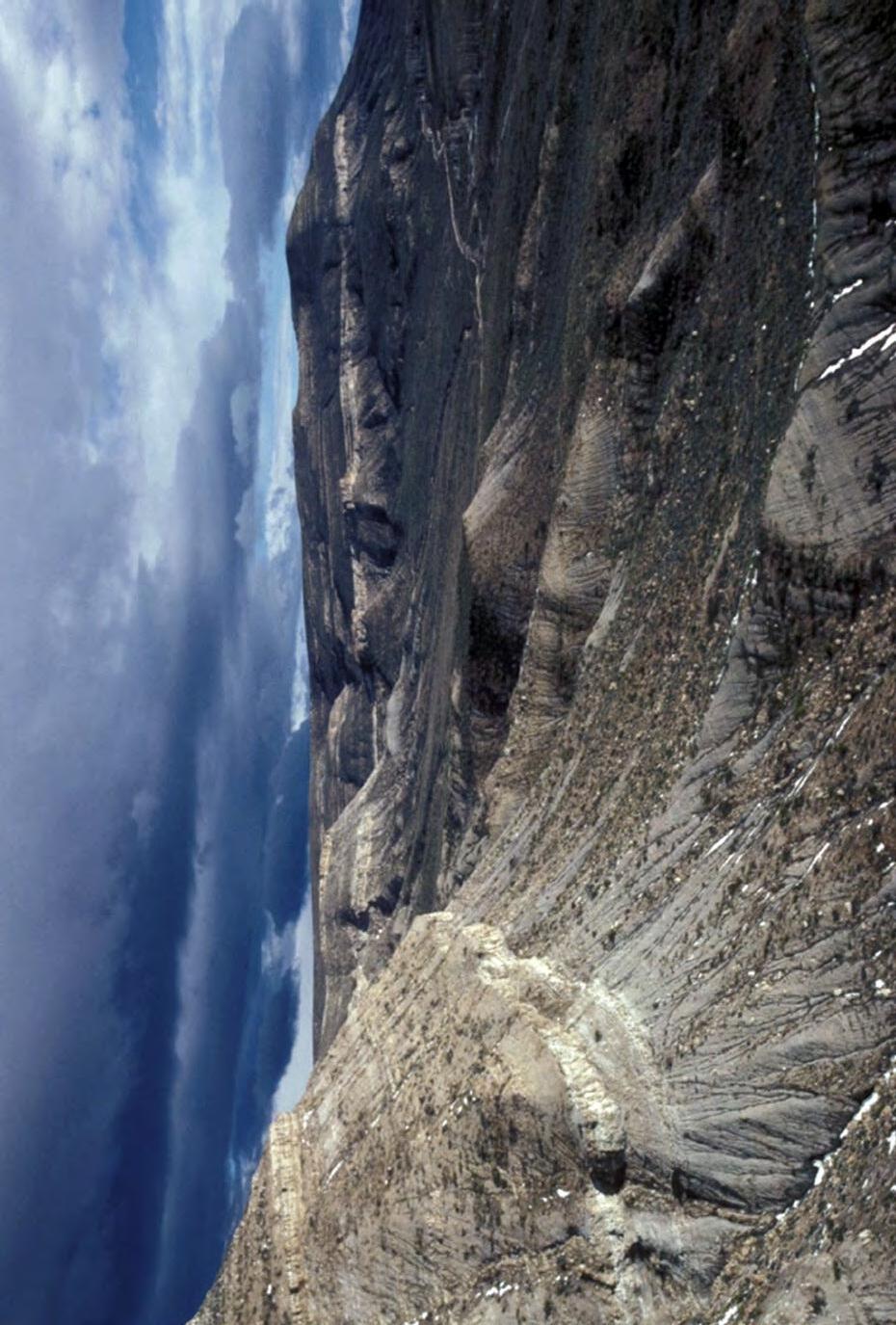
Plate 2The breathtaking view at la Sierra de Chacaico, Neuquén B asin, Argentina. The Jurassic fluvio-deltaic Lajas . Formation resting upon deeper water Jurassic strata of the Los Molles Formation.
CHAPTER I: General concepts TURBIDITE SYSTEMS: AN OUTCROP-BASED ANALYSIS 17
A B
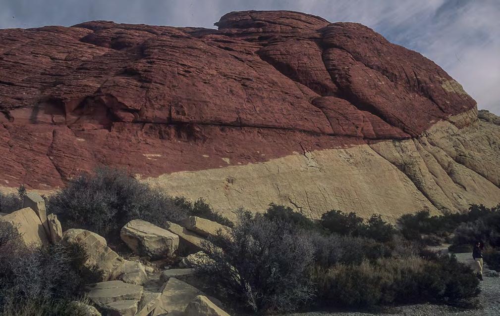
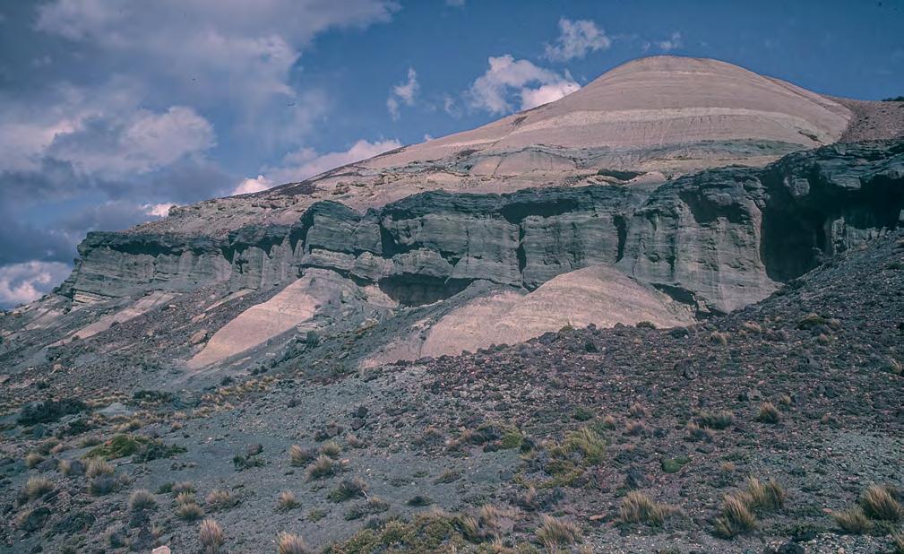
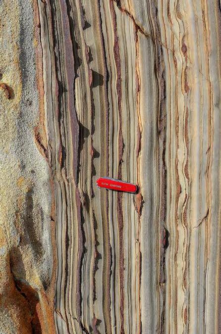
Plate 3 - The beauty of colors. A - Triassic aeolian sandstones in Red Canyon, Nevada. Note that the sharp color boundary is time-transgressive since it cuts bedding surfaces. B - Green and yellowish volcaniclastic lacustrine deposits (Cretaceous, San Jorge Basin, Argentina).
I: General concepts TURBIDITE SYSTEMS: AN OUTCROP-BASED ANALYSIS 18
CHAPTER
C D A B
Plate 4The beauty of primary sedimentary structures. Broad and shallow festoons in estuarine sandstones of the late Oligoceneearly Oligocene Patagonia Formation, Golfo San Jorge basin, Argentina (A); water escape structures in the Oligocene Capod di Orlando Fm, Calabria, southern Italy (B); current ripples in a modern stream (C); early Cretaceous rippled sandstone beds, Japaratinga region, Brazil (D).
CHAPTER I: General concepts TURBIDITE SYSTEMS: AN OUTCROP-BASED ANALYSIS 19
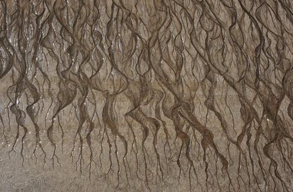
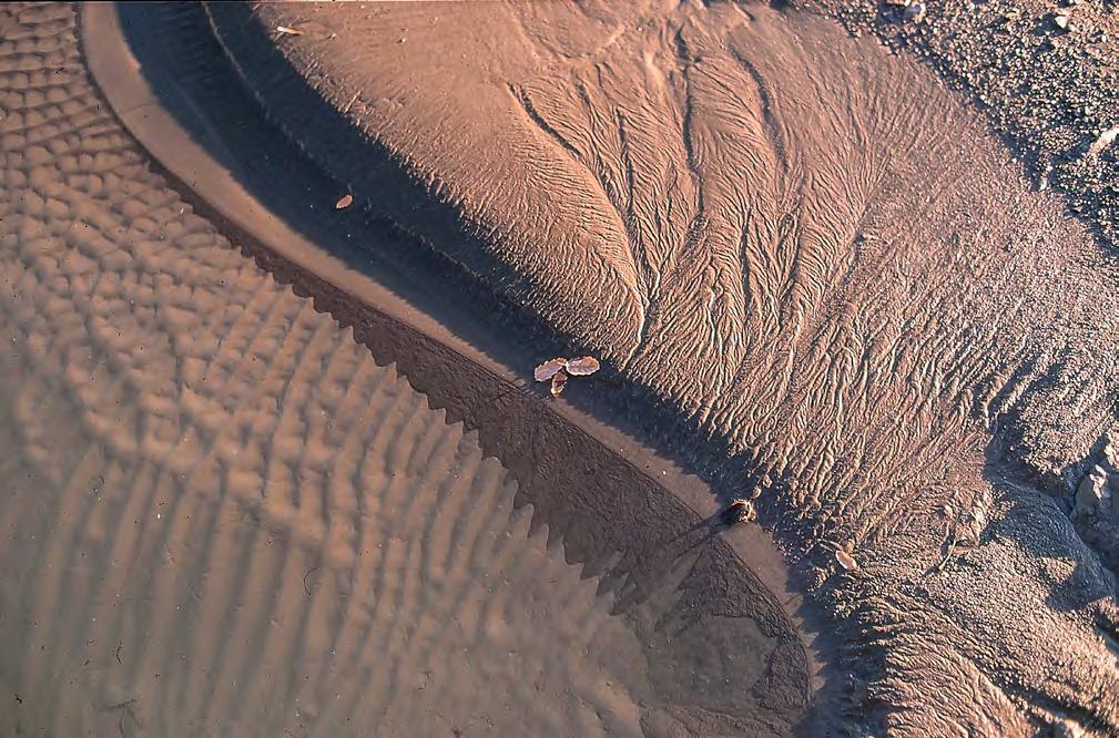
Plate 5 - Dendritic flow pattern at low tide, Japaratinga beach, Brazil.
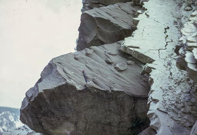
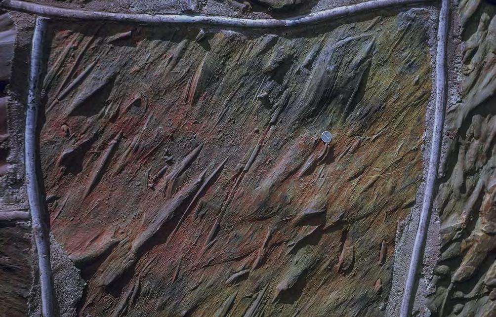
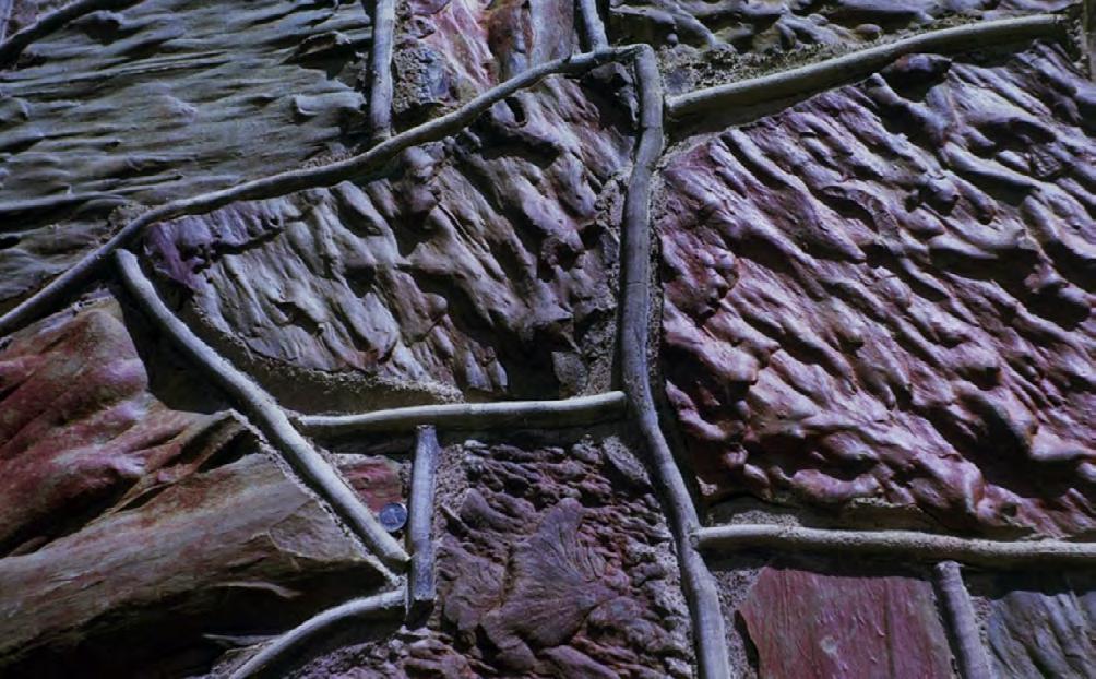
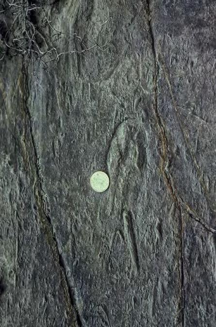
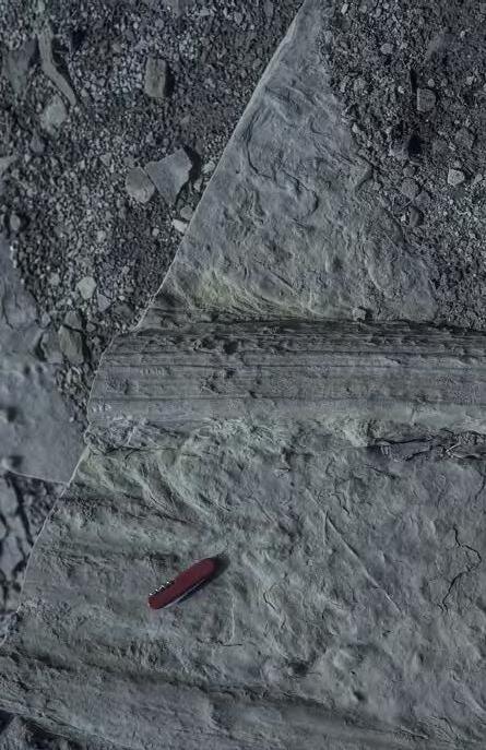
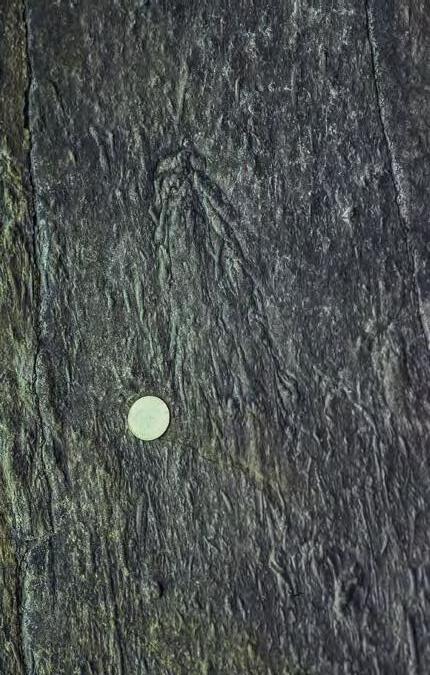
Plate 6 - The beauty of the sole markings preserved as casts (counterparts) at the base of sandstone beds. For the interested reader, these features are described and interpreted in the classic paper of Dzulynski and Sanders (1962). Basically, all these structures record the erosion of a muddy substratum by sediment gravity flows in both terrestrial and subaqueous environments, though being most common in turbidite sediments. In addition to their beauty, sole markings are fundamental for studies on paleocurrent direction and flow characteristics, as well as in structural geology for recognizing upside down successions. A and B - Counterparts of flute marks (flute casts, FC) at the base of sandstone beds in the Eocene Monte Sporno Flysch of the northern Apennines.
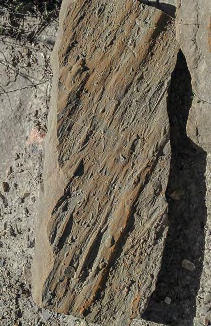
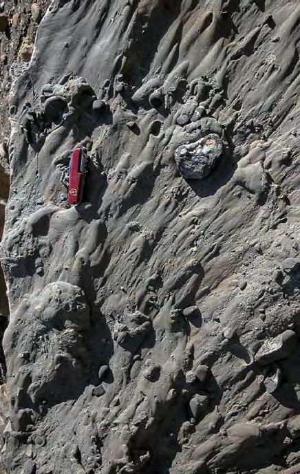
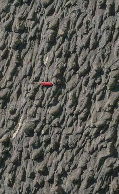
Plate 7A –Scour casts including small flute casts (FC) with pointed head upcurrent and crescent casts (CC) formed in the upcurrent side of obstacles in the bottom. Eocene Ainsa system, south-central Pyrenees. B –Association of tool casts (groove casts, GC) and scour casts (flute casts, FC).
Miocene Marnoso-arenacea Formation, northern Apennines. C –Tool casts, including bounce casts (BC) and small prod casts (PC). The asymmetry (steeper downcurrent slope) of the latter allow to recognize the downflow direction. Eocene Ainsa system, south-central Pyrenees.
D –Flute casts covering the entire basal surface of a sandstone bed and indicating bed erosion through diffuse turbulence. Miocene Manoso-arenacea Formation, northern Apennines.
CHAPTER I: General concepts TURBIDITE SYSTEMS: AN OUTCROP-BASED ANALYSIS 20
C D A B
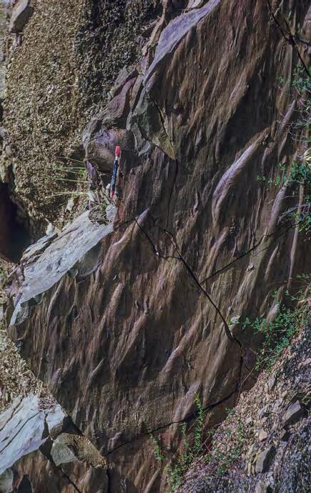
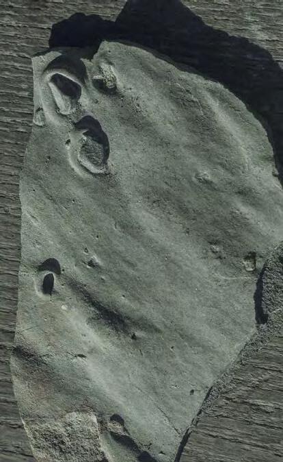
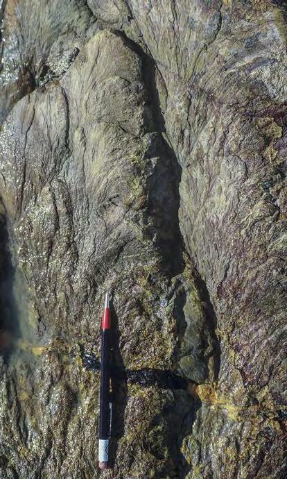
Plate 8A –Scour casts including small flute casts (FC) with pointed head upcurrent and crescent casts (CC) formed in the upcurrent side of obstacles in the bottom. Eocene Ainsa system, south-central Pyrenees. B –Association of tool casts (groove casts, GC) and scour casts (flute casts, FC).
Miocene Marnoso-arenacea Formation, northern Apennines. C –Tool casts, including bounce casts (BC) and small prod casts (PC). The asymmetry (steeper downcurrent slope) of the latter allow to recognize the downflow direction. Eocene Ainsa system, south-central Pyrenees.
D –Flute casts covering the entire basal surface of a sandstone bed and indicating bed erosion through diffuse turbulence. Miocene Manoso-arenacea Formation, northern Apennines.
CHAPTER I: General concepts
SYSTEMS: AN OUTCROP-BASED ANALYSIS 21
TURBIDITE
C D A B
CHAPTER I: General concepts TURBIDITE SYSTEMS: AN OUTCROP-BASED ANALYSIS 22
A B
Plate 9 - Exterior wall of a house made of turbidite sandstones (Pennsylvanian Atoka Formation) ornamented by a variety of well-preserved and beautiful sole markings, Oklahoma, USA.A – Bounce casts; B – Mostly flute casts.
TURBIDITE
Cretaceous Panther Tongue Member, Utah, USA. B –Large groove cast associated with a bounce cast and small flute casts. Note the divergence of paleocurrent direction at the base of the same bed, a feature that is commonly observed in thick turbidite sandstone beds. Eocene Ainsa system, southcentral Pyrenees. C and D –Examples of brush casts, an asymmetric tool mark that indicates the downcurrent direction. Eocene Broto (Arrò) system, south-central Pyrenees.
Plate 10A –Large groove cast at the base of a sandstone bed deposited by a hyperpycnal flow.
CHAPTER I: General concepts
SYSTEMS: AN OUTCROP-BASED ANALYSIS 23
C D A B
CHAPTER I: General concepts TURBIDITE SYSTEMS: AN OUTCROP-BASED ANALYSIS 24
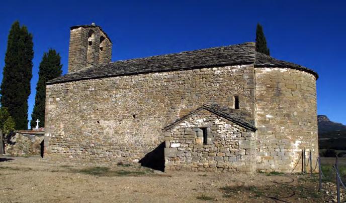
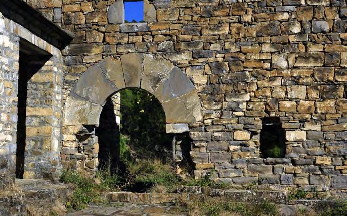
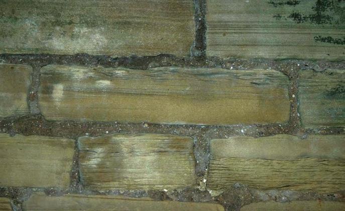
Plate 11 - The beautiful romanesque churches of the South-Central Pyrenees have usually their exterior walls made of turbidite or delta-font sandstone stones from originally tabular beds. These walls contain a wealth of sedimentological information in terms of internal depositional structures.
I: General concepts TURBIDITE SYSTEMS: AN OUTCROP-BASED ANALYSIS 25
CHAPTER
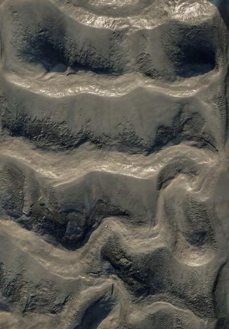
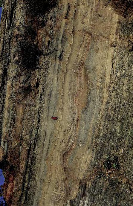
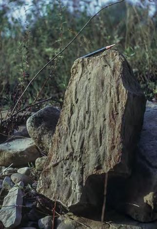
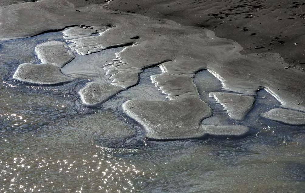
Plate 12 - Degradational structures in the bank of small rivers forming during the falling stage of minor flood events.
CHAPTER I: General concepts TURBIDITE SYSTEMS: AN OUTCROP-BASED ANALYSIS 26
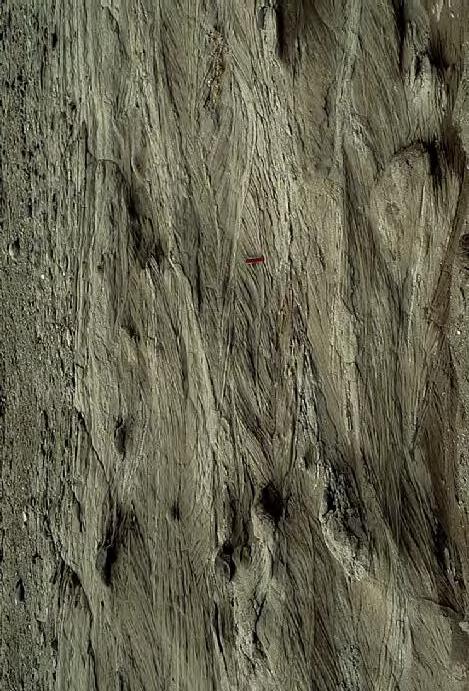
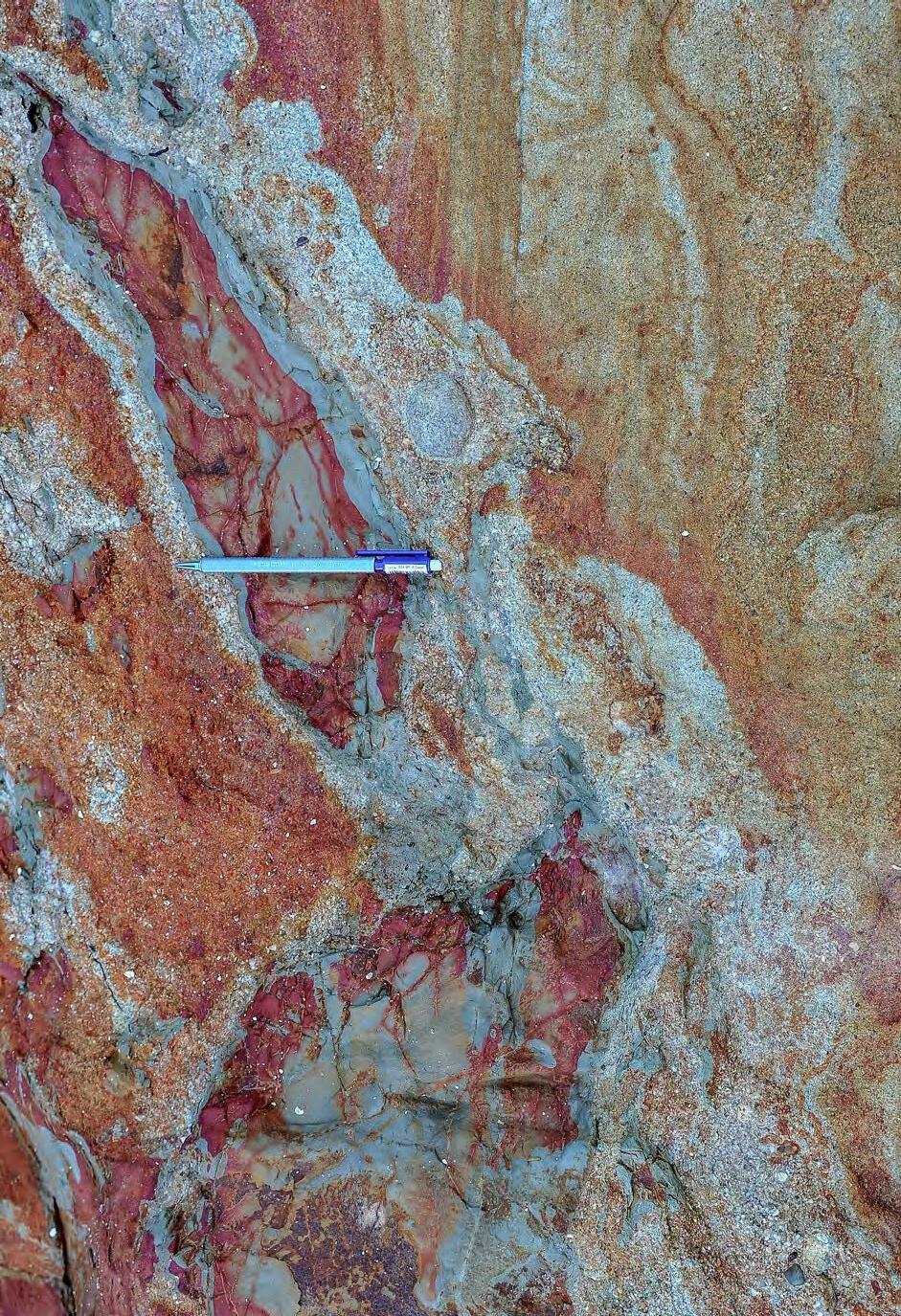
Plate 13Diagenetic color patches and bands. A mudstone-clast breccia with coarse-grained matrix cutting into a sandstone bed.
I fell in love with sedimentary geology when I was around 21 and wanted to become a medical doctor. At that time, I was actually used to spend most of my time with my dog hunting partridges and woodcocks in the mountains around my home village, Nociveglia, in the northern Apennines. One day I was driving across the mountains and suddenly I was struck by the magnificent outcrop of the Mount Cassio Flysch in the Baganza valley, near Parma (Figure 3). I knew very little about geology at that time, but I remained impressed by the layering and the colours. What did they mean? A few months later I started studying geology.
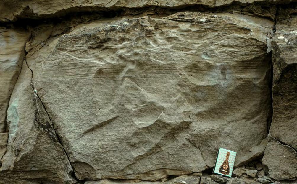
More than five centuries before, I think that Jan van Eyck (1390-1441), a Flemish naturalistic painter of the 15th century who developed the technique of oil painting, had also to be struck by the beauty of an exposure that is shown in his painting entitled “St. Francis receiving the stigmata” (Figure 4). There are two almost identical paintings with the same title, one dated 1428
is at the Philadelphia Museum of Art, the other dated 1434 at the Galleria Sabauda, Turin. In the right side of both paintings there is a three-dimensional exposure of rock where one can see in great detail an alternation of thick (some 40 cm) and thin (some 2-10 cm) beds with internal laminae and colour bands. The beds, almost certainly sandstone beds, are separated by very thin, softer and darker partings (shale) and have a roughly tabular geometry. Angular blocks which fell down from the exposure contain whitish shells (probably oysters) and shell fragments on their surfaces.
The naturalistic approach of van Eyck and his superb technique result in an extraordinary reproduction of those rocks. That portion of the painting resembles very closely a modern high-quality photograph. The painter obviously had to love the mysterious rocks he was painting without knowing what in reality they were. He certainly liked their beauty and their mystery to the point that they became part of a highly touching religious scene.
CHAPTER I: General concepts TURBIDITE SYSTEMS: AN OUTCROP-BASED ANALYSIS 27
Fig. 3 - The spectacular exposure of the upper Cretaceous Monte Cassio Flysch. Baganza valley, northern Apennines.

The painting is so detailed, in spite of its size (29.2 x 33.4 cm for the copy in Turin I could examine), that is tempting to try a sedimentological interpretation of these rocks five centuries later. My personal interpretation is that the exposure shows sharp-based sandstone beds which might be turbidites or flood-dominated delta front sandstones (shallow-water turbidites). The exposure had to be along a rocky beach as testified by encrusting oysters on the fallen blocks and ubiquitous traces of boring organisms also in the uppermost part of the exposure, suggesting a rocky shoreline undergoing high and low tides. It can be speculated that Jan van Eyck found this exposure somewhere along the coasts of south-western France,
northern Spain or Portugal, during a diplomatic mission for the Duke of Burgundy in 1426. I’m quite sure that the exposure must exist somewhere and is probably described in a paper by a geologist unaware of the van Eyck’s painting.
Leonardo da Vinci (1492-1519) also paid attention to layering in some drawings and in the painting “The Virgin of the Rocks” (in the copy at the Louvre) where beds and internal laminae are carefully reproduced, probably a memory of some turbidite sandstone beds he had seen somewhere when travelling across the northern Apennines or observing exterior walls of many buildings in Florence.
CHAPTER I: General concepts TURBIDITE SYSTEMS: AN OUTCROP-BASED ANALYSIS 28
Fig. 4 - Jan van Eyck (1390 – 1441) – St. Francis receiving the stigmata, Galleria Sabauda, Turin, Italy.
I.2 - LAYERING AND BEDS
Since beds are the main subject of this book, it may be appropriate to review some aspects of layering in some depth. As stated by Johannes Walther (1894, p.623; fide C.V. Campbell, 1967, his p. 7) “… No problem of geology compares in importance with the question of the origin of bedding…. What is bedding? How does it originate? What does it prove?”.
Nicholas Steno (1638-1686), in his “De solido intra solidum naturaliter content dissertationis prodromus” (1669), was the first to analyze and interpret layering as a natural phenomenon whereby deposition would take place horizontally layer upon layer, spread out by the action of water, thus setting the basis for relative chronology in stratigraphic studies. His geometrical drawings (Figure 5) with angular unconformities and onlap relationships are incredible precursors of modern seismic stratigraphy, and his interpretation of layers as a result of deposition from a fluid heralds the settling velocity of small particles of the Stokes’ law. The birth of stratigraphy is certainly there.
For Lyell (1871, p.3), the author of the great Principles of Geology, “The term stratum means simply a bed, or anything spread out or ‘strewed’ over a given surface; and we infer that these strata have been generally spread out by the action of water, from

what we daily see taking place near the mouth of rivers, or on the land during temporary inundations. For, whenever a running stream charged with mud or sand, has its velocity checked, as when it enters a lake or sea, or overflows a plain, the sediment previously held in suspension by the motion of the water, sinks by its own gravity, to the bottom. In this manner layers of mud and sand are thrown down one upon another.” These conclusions are basically the same as those reached by Nicholas Steno in 1669 (see above). Charles Lyell did not further elaborate on the problems of bedding. Derek Ager (1993), who was a tenacious defender of the “catastrophist” Georges Cuvier, thought that the Frenchman was a better geologist than the “uniformitarian” Charles Lyell. According to Ager (op. cit.), Lyell generalized and theorized, whilst Cuvier carefully looked at rocks as documented by his detailed stratigraphic studies in the Paris basin. The scant regard of Lyell for layering stands out from the comment G.P. Scrope sent to him after the publication of the second volume of Principles of Geology: “It is a great treat to have taught our section-hunting quarry men that two thick volumes may be written on geology without once using the word ‘stratum’“(vide Ager, 1993, p.2). Fortunately, each geologist has his own scale of observation and his preferences, otherwise geology would be boring.
CHAPTER I: General concepts TURBIDITE SYSTEMS: AN OUTCROP-BASED ANALYSIS 29
Fig. 5 - STENONIS NICOLAI (1638-1686). “De solido intra solidum naturaliter contento dissertationis prodromus.” Florentiae, 1669. Layers are originally horizontal and tend to be laterally continuous. Sedimentation takes place layer-upon-layer, hence, the bed above is younger than the bed below. A. Example from the Jurassic shallow-marine strata of the Lajas Formation, Neuquén Basin, Argentina Stratigraphic unconformity. B. Upper Eocene and Oligocene alluvial conglomerates resting upon upper Cretaceous and Paleocene strata through an angular unconformity, south-central Pyrenees.
1638-1686
STENONIS NICOLAI
De solido intra solidum naturaliter contento dissertationis prodromus. Florentiae, 1669
A B
Terms like layer, stratum, bed, laminae started to become widely used in the literature in the past century and several definitions were offered, based on lithology, thickness and other criteria (e.g., Payne, 1940; Shrock, 1948; McKee and Weir, 1953; Krumbein and Sloss, 1958; Botvinkina, 1962; McBride, 1962; Campbell, 1967; Bosellini et al., 1989). In reality, the limited number of reseachers who spent time thinking about stratification seems to suggest that for some reason beds, laminae and layering have never been an attractive subject among sedimentologists.
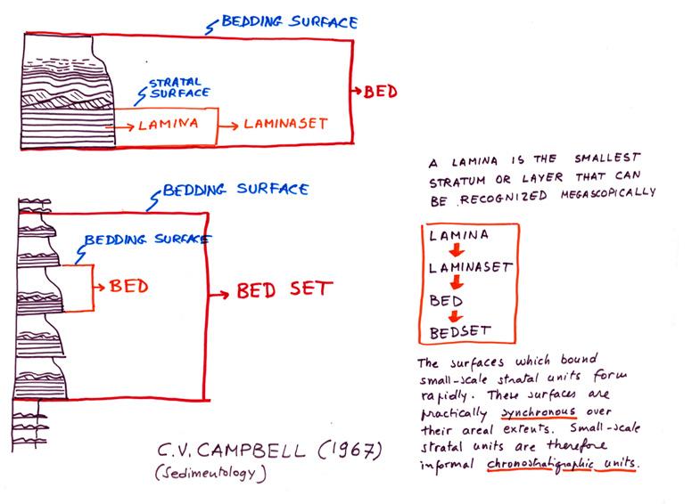
Here I will mainly follow definitions and concepts set forth by C.V. Campbell (1967) which are simple, clear and of great stratigraphic relevance. The author recognizes four types of sedimentary layers or strata, which from the smallest to the largest include laminae, laminasets, beds, and bedsets; each of the four types of layers can be considered as a sedimentation unit formed during similar conditions; compared with each other, these strata differ mainly in lateral extent and length of time for formation. Surfaces separating individual strata, termed stratal surfaces, are thought
to be practically synchronous; as a consequence, a layer bounded by two stratal surfaces is an informal chronostratigraphic unit of limited areal extent and of relatively short time span. Since seismic reflectors follow the different types of stratal geometry, the author also concludes that seismic lines can be interpreted in terms of informal chronostratigraphic units – a conclusion that will form the conceptual basis for the seismic sequences of Vail et al. (1977) and later for the sequence stratigraphy of Posamentier et al. (1988) and Vail et al. (1991) (see later).
According to Campbell (1967), a stratum is a layer of rock or sediment that is visually or physically more or less distinctly separated from layers above and below by stratal surfaces (Figure 6). A lamina is the smallest observable stratum; a laminaset consists of a group of conformable laminae that form a distinctive division within a bed; a bed is a stratum that reveals the principal rock layering. Because beds are usually the most readily recognizable layers, they can be considered the fundamental component of sedimentary rocks. A bedset consists of a number of superimposed, similar beds (Figures 7 and 8).
CHAPTER I: General concepts TURBIDITE SYSTEMS: AN OUTCROP-BASED ANALYSIS 30
Fig. 6 - Example of bed and its component laminasets and laminae according to the conceptual scheme of Campbell (1967). Lacustrine delta-front sandstone lobes from the Oligocene Ebro basin, south-central Pyrenees.
bed
laminaset
lamina
Time for the formation of laminae, laminasets, beds, and bedsets as well as of their bounding surfaces is generally short. Laminae may form in a few seconds; bedsets in tens of years to few thousands of years. The areal extent of these stratal units is depending upon the environment of deposition and the processes which are operative in each specific environment. In some turbidite deposits, beds and bedsets can be basinwide features. In other environments (e.g., nearshore or fluvial), stratal units may have areal extent of only a few square meters or less. Regardless of their absolute values, both the time for formation and the areal extent of these stratal units in-
crease from the smallest to the largest. It will be noted that laminae and beds have no limiting thickness nor lithologic constraints, in contrast with most previous classifications (e.g., McKee and Weir, 1953).
Though conceptually satisfactory, the Campbell’s classification of stratal units encounters some problems in its practical application. The more we know about sedimentary structures and their possible hydrodynamic interpretation, the more difficult and sophisticated is the recognition of beds and their bounding surfaces (see later).
CHAPTER I: General concepts TURBIDITE SYSTEMS: AN OUTCROP-BASED ANALYSIS 31
Fig. 7 - Lamina, laminaset, bed and bedset according to Campbell (1967).


Beds, their bounding surfaces and their internal depositional structures (laminae and laminasets) are the basic key to an understanding of modern facies analysis and the many stratigraphic problems involved. Yet, beds taken in isolation may offer an excellent subject for pure sedimentological investigations but fail to reveal the context in which their deposition took place. Thus, placing beds in their context is fundamental. For this reason, the following sections introduce and discuss at length some basic principles of stratigraphic and facies analysis that should help stratigraphers and sedimentologists to frame laminae, laminasets, beds and bedsets within the complex framework of depositional units.
II - STRATIGRAPHIC UNITS, THEIR BOUNDING SURFACES AND BASIC PRINCIPLES OF SEQUENCE
STRATIGRAPHY
Sedimentary rocks are basically layered successions where sediments pile up as discrete bodies separated by surfaces. This holds true at every physical and temporal scale, from that of mm-thick laminae observable within beds and deposited in few seconds to that of a seismic reflection profile depicting large-scale basin fill architectures implying periods of time up to tens of millions of years.
Geologists have long attempted to put some order in this general pattern developing models and related
CHAPTER I: General concepts TURBIDITE SYSTEMS: AN OUTCROP-BASED ANALYSIS 32
A B
These two different kinds of bedset can also be considered as two distinct types of facies (see later). Oligocene Capo d’Orlando Fm., Calabria, southern Italy.
terminologies that vary from the Bouma sequence, applicable to an individual turbidite bed, to the sequence stratigraphy that may be applicable to an entire basin fill.
Each attempt considers at different scales volumes of sediment separated by surfaces. The historical development of these concepts started with Steno (1669) who first recognized layering and its importance and significance in the upbuilding of sedimentary successions (see above), and has ended, for the time being, with Vail et al. (1977), Posamentier et al. (1988) who suggested, in a series of breakthrough contributions, that sedimentary successions build up through cycles of relative sea level variations. These cycles are recorded by depositional sequences bounded by unconformities and their correlative conformities and displaying an internal predictable succession of systems tracts named lowstand, transgressive and highstand systems tracts after their
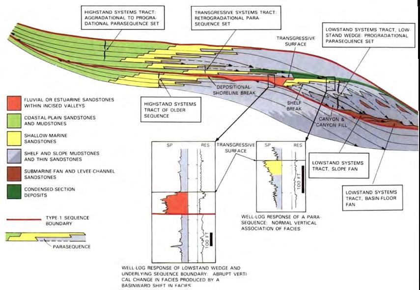
position along the different intervals of the cycle of relative sea level variation (Figure 9). A systems tract is the linkage of contemporaneous depositional systems (Brown and Fisher, 1977). Sequences and systems tracts are large-scale units defined by surfaces, and systems tracts are further characterized by their internal stratal configuration expressed by parasequences, which are lower-rank units bounded by flooding surfaces (Van Wagoner et al., 1988), and parasequencesets (Figure 10). These basic concepts and their many derivatives and variants (and ensuing confusion and semantic problems) are discussed at length in a number of papers (e.g., Galloway, 1989; Embry and Johannessen, 1992; Hunt and Tucker, 1992; Posamentier and Allen, 1999; see Catuneanu, 2006, and Catuneanu et al. 2011, for extensive reviews, pertinent references, and attempts to clarify concepts, problems and terminology).
CHAPTER I: General concepts TURBIDITE SYSTEMS: AN OUTCROP-BASED ANALYSIS 33
Fig. 9 - Stratal patterns and systems tracts in a type 1 depositional sequence (from Van Wagoner et al., 1988).
For the reader’s convenience, Figures 11 and 12 show the different types of sequences as envisaged by different authors, as well as the related differences in the timing of systems tracts and sequence boundaries.
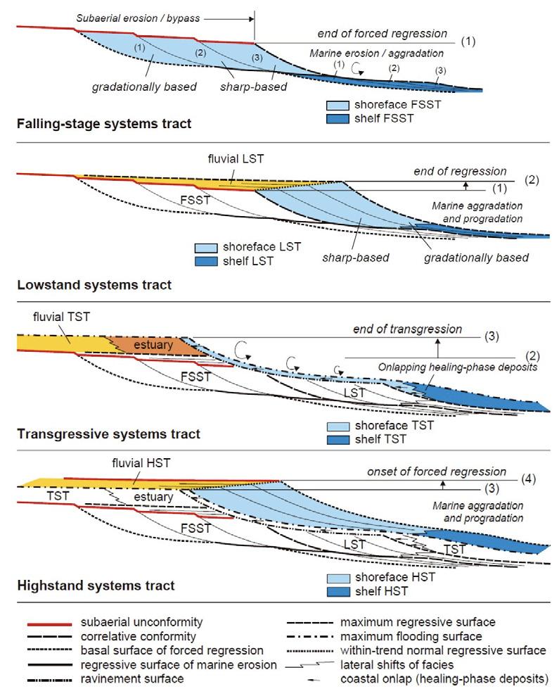
Figure 13 shows the more complex architecture of a depositional sequence as offered by Catuneanu (2006). In the Exxon model sea level fall was thought to be extremely rapid, leaving no stratigrahic record except for an unconformity surface and a basin-floor turbidite system. The scheme of Figure 13 also incorporates the falling-stage systems tract produced by forced regressions when accommodation becomes negative at the shoreline, which is forced to move seaward and step down through very distinctive stratal patterns (Hunt and Tucker, 1992; Nummedal, 1992; Ainsworth, 1994; Plint and Nummedal, 2000).
Comparing these new schemes with the Exxon model of Figure 9 leaves no doubt that sequence stratigraphy is now developing highly conceptual models that will be increasingly difficult to apply in the practice in absence of
high-resolution seismic data. Probably, most recent work is too focused on shelfal, nearshore and coastal setting, overlooking deep-water sedimentation, i.e, turbidite and contourite systems, or treating them in a somewhat cursory way. As a consequence, the sequence stratigraphic relationships between shallow- and deep-marine sedimentation remain poorly understood. In the Exxon scheme, the turbidite basin-floor fan lies above a surface which is correlative with a subaerial unconformity. Catuneanu (2006) apparently prefers to follow the Hunt and Tucker (1992) interpretation whereby the basin-floor fan lies below the unconformity that forms diachronously landward of and above each downstepping “stranded” parasequence during falling sea level, though Posamentier and Allen (1999) placed the unconformity at the beginning of the forced regression. These discrepancies and their very important bearing on the interpretation of deep water depositional systems, are amply discussed in the next chapter. According to Catuneanu (2006), the main events and surfaces associated with the development of a sequence and its component systems tracts are those illustrated in Figure 13 A.
CHAPTER I: General concepts TURBIDITE SYSTEMS: AN OUTCROP-BASED ANALYSIS 34
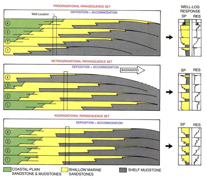
Fig. 10 - Vertical stacking patterns of aggradational, retrogradational and progradational parasequence sets (from Van Wagoner et al., 1988).
Abbreviations: RLS – relative sea level; T – transgression; R – regression; FR – forced regression; LNR – lowstand normal regression; HNR – highstand normal regression; LST – lowstand systems tract; TST – transgressive systems tract; HST – highstand
RST
CHAPTER I: General concepts TURBIDITE SYSTEMS: AN OUTCROP-BASED ANALYSIS 35
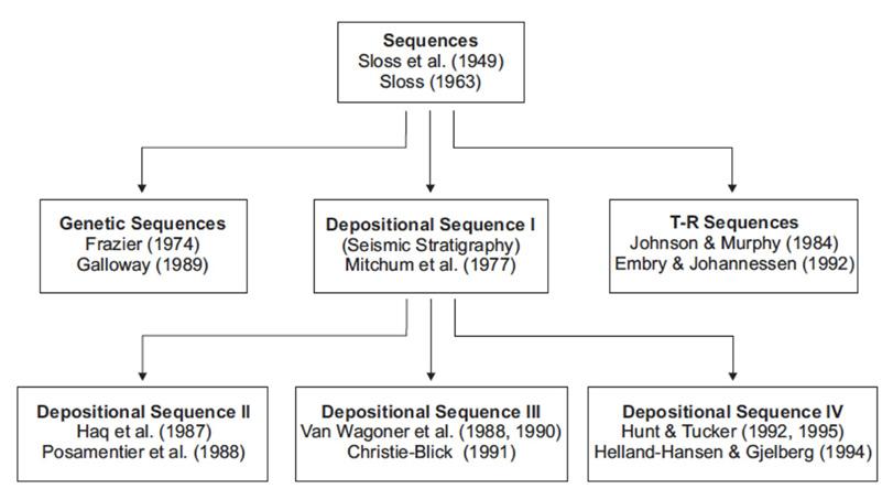
Fig. 11 - Evolution of sequence-stratigraphic approaches (from Catuneanu et al., 2011).
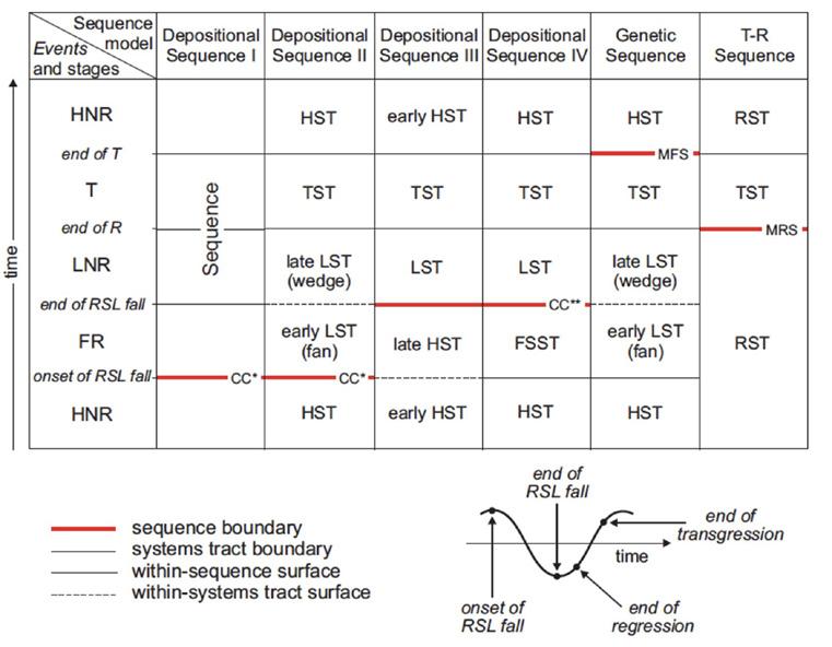
Fig. 12 - Nomenclature of systems tracts, and timing of sequence boundaries for the various sequence stratigraphic currently in use (from Catuneanu, 2006).
systems tract; FSST – falling-stage systems tract;
– regressive systems tract; T-R – transgressive-regressive; CC* - correlative conformity in the sense of Posamentier and Allen (1999); CC** - correlative conformity in the sense of Hunt and Tucker (1992); MFS – maximum flooding surface; MRS – maximum regressive surface.
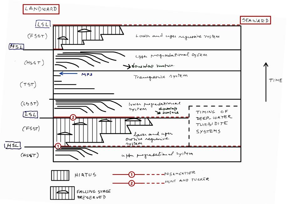
Figures 14 is my personal attempt to clarify and simplify part of these problems and related terminology by showing the main sequence stratigraphic events and open problems as related to a cycle of base level or relative sea level variation, as well as by suggesting a simpler geological terminology.
Figure 15 shows a Wheeler-type of simplification of the problem, indicating stratal (seismic) configurations of the different types of depositional systems as primarily related to accommodation variations as well as the suggested timing of more basinal
turbidite deposition. This timing is probably the most common, though turbidite deposition is also reported from other portions of the sea level cycle and is certainly strictly related also to variations of sediment flux to the sea (Mutti et al., 1999, 2003). The problem will be amply discussed in the following chapters. As shown in the sketch of Figure 15, sequence boundaries and timing of turbidite deposition are closely related and their definition largely depends upon the surface that is chosen as sequence boundary (see above).
CHAPTER I: General concepts TURBIDITE SYSTEMS: AN OUTCROP-BASED ANALYSIS 36
Fig. 13 - The component systems tract of a depositional sequence according to Catuneanu (2006).
A PERSONAL AND SIMPLIFIED SUMMARY OF SEQUENCE STRATIGRAFIC CONCEPTS
LOWEST SEALEVEL
Fast falling sealevel
HIGHEST SEALEVEL
LOWEST SEALEVEL
TIME
MFS: maximum flooding surface
Unconformity is created during stages 4 and 5
AB
Full cycle
THE SCHEME DESCRIBES COASTAL PLAIN, NEARSHORE AND SHELFAL SETTINGS
Subaerial erosion with limited preservation of forced regression wedges. Upper erosive regressive system
Beginning of subaerial erosion and forced regression wedges. Lower erosive regressive system
Upper progradational system (depositional regression)
Transgressive system
Lower progradational system (depositional regression)
Negative accommodation (space is removed at different rates)
Positive accommodation (new space is added at different rates)
CHAPTER I: General concepts TURBIDITE SYSTEMS: AN OUTCROP-BASED ANALYSIS 37
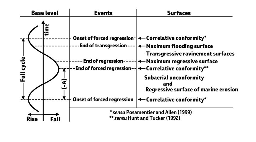
Fig. 13 A - Main events and surfaces in a full cycle of base-level variation (from Catuneanu, 2006).
Fig. 14 - A personal and simplified summary of sequence-stratigraphic events and sedimentation associated with an ideal full cycle of baselevel variation.
Slowly falling sealevel Slowly rising sealevel Fast rising sealevel Slowly rising sealevel Stages 1 2 3 4 5 MFS
A
B
CHAPTER I: General concepts TURBIDITE SYSTEMS: AN OUTCROP-BASED ANALYSIS 38
Fig. 15 - Wheeler-type of simplification showing the basic stratal configuration of the different types of depositional systems, the problem of the unconformity (one surface above the erosive regressive system or a time interval including the beginning of the erosive regression and ending at the maximum sea-level lowstand), and the timing of turbidite systems formation. For graphic clarity reasons, the falling stage time has been arbitrarily shortened.
Hierarchical order Duration (My) Cause First order 200-400 Formation and breakup of supercontinents Second order 10-100
changes in
spreading centers
order 1-10
plate kinematics Fourth and fifth order 0.01-1 Orbital forcing
Fig. 16 - Geodynamic and orbital control on eustatic sea-level fluctuations. Local structural deformation may affect duration and magnitude of relative sea-level variations (from Catuneanu, 2006).
Volume
mid-oceanic
Third
Regional
Cycles of relative sea level variations, originally considered as essentially related to relatively long-term and mainly eustatically-driven variations of sea level and typically expressed by seismic depositional sequences (3rd order-cycles of Vail et al., 1977), were later recognized as an additional and important controlling factor in the development of a higher-frequency cyclicity and related sequences (Mitchum and Van Wagoner, 1991; see also Mutti, 1979, 1990, and Mutti et al., 1988, 1994). This led to introduce 4th and 5th order depositional sequences and the problem of their genetic relations to parasequences. For the reader’s convenience, Figure 16 shows the different orders of sedimentary cyclicity as well as their possible origin. Following Catuneanu (2006), cycles of relative sea level variations and base-level variations are here used as essentially synonymous. Conceptually similar is also the accommodation succession method suggested by Neal and Abreu (2009), emphasizing stacking patterns produced by progradation to aggradation (PA), retrogradation (R), and aggradation to progradation followed by degradational forced regressions (see their Figure 1, p. 780).
It would be beyond the scope of this book to review all the problems mentioned above, their historical development, and the many related enthusiastic or controversial opinions. However, two main achievements appear to stand out. The first one is our increasingly better understanding of sedimentological processes that govern the formation of beds and their internal structures, that is, the most common type of layering observable in outcrop and core analysis. Especially during the last 50 years, this kind of layering has been studied in great detail and has led to a substantial improvement of our understanding of depositional and erosional structures produced by various types of flow (e.g., fluvial currents, waves, tides, sediment gravity flows, wind, and bottom currents), thus providing an invaluable tool for facies analysis and for the recognition of depositional systems. The latter, introduced by Fisher and McGowen (1967) and Brown and Fisher (1977), with emphasis on their seismic expression and their characteristics inferred from modern environments, have thus become recognizable and mappable stratigraphic units on the basis of their facies and reasonably inferred processes and environments, offering a valuable alternative to stratigraphic units previously defined only through their lithological characteristics (the well-known lithostratigraphic units).
The second achievement is certainly the renewed interest in classic concepts such as regressions and transgressions, unconformities, accommodation (subsidence, uplift and eustatic variations), climate changes and sediment supply, and sedimentary cyclicity
brought about by sequence stratigraphy. This has led to recognize the highly dynamic stratigraphic architecture of basin fills that formed in complex, ever-changing conditions of paleogeographic settings created by relative sea level variations, unconformities, depositional and forced regressions, and transgressions.
With time and along with improvements of sedimentological analysis, sequence stratigraphy has gradually changed our stratigraphic approach to the study of sedimentary rocks replacing the static lithostratigraphic units with a geologically more significant way of organizing our observations and thinking in terms of a more dynamic basin analysis. Comparing basin fills described in terms of groups, formations and members of classic lithostratigraphy with those described and interpreted in terms of depositional sequences and their components systems tracts and parasequences highlights the substantial improvement of our understanding of stratigraphic successions.
Unfortunately, the general enthusiastic acceptance of this new way of thinking has led to the tendency to overlook sediments and their facies. Current models, mainly derived from seismic reflection data, most commonly describe sediments not based on their intrinsic characteristics, such as facies and facies associations, but rather in terms of their relative position within accommodation cycles. As a result, depositional systems and their tracts are described in most recent literature directly as lowstand, transgressive, highstand and falling-stage deposits rather than in terms of what they really are from a sedimentological standpoint. Depositional sequences and their component systems tracts have thus become somewhat conceptual units with emphasis on the different kinds of surface that permit their recognition (Figure 13), but with little information on their basic components which should remain facies and facies associations and the environments they should record.
Attempts have been also made recently to formalize sequence stratigraphic units and surfaces in order to provide stratigraphers with standard criteria for their recognition and to reconcile different conceptual models developed with time and related terminology (Catuneanu et al., 2009, 2011). In my long experience, attempts to formalize stratigraphic units are an approach implying the acceptance of a paradigm or model in the very elusive and subjective domain of subdividing stratigraphic successions into “objective” units. With very few exceptions, I do not have memory of any stratigraphic problem I faced in my career where everybody would fully agree on boundaries and even on units to choose to work with. The problem is
CHAPTER I: General concepts TURBIDITE SYSTEMS: AN OUTCROP-BASED ANALYSIS 39
commonly left with personal background, purposes of the work, the time available and the knowledge of the regional and local geological setting based on both personal work and available literature (sometimes not in English).
III - TRANSGRESSIONS, REGRESSIONS AND UNCONFORMITIES
These basic concepts date back almost to the birth of stratigraphy but the renewed interest in their meaning and importance has been greatly emphasized by sequence stratigraphy. In their classic meaning, transgressions and regressions refer to the position of the shoreline. A transgression takes place when the coastline moves landward, and a regression occurs in the opposite case. For most old-school geologists, a transgression would be typically expressed by marine fossiliferous sandstones resting above a continental deposit and a regression would be the opposite. Introducing relative sea level variations, the picture becomes more complex and interesting.
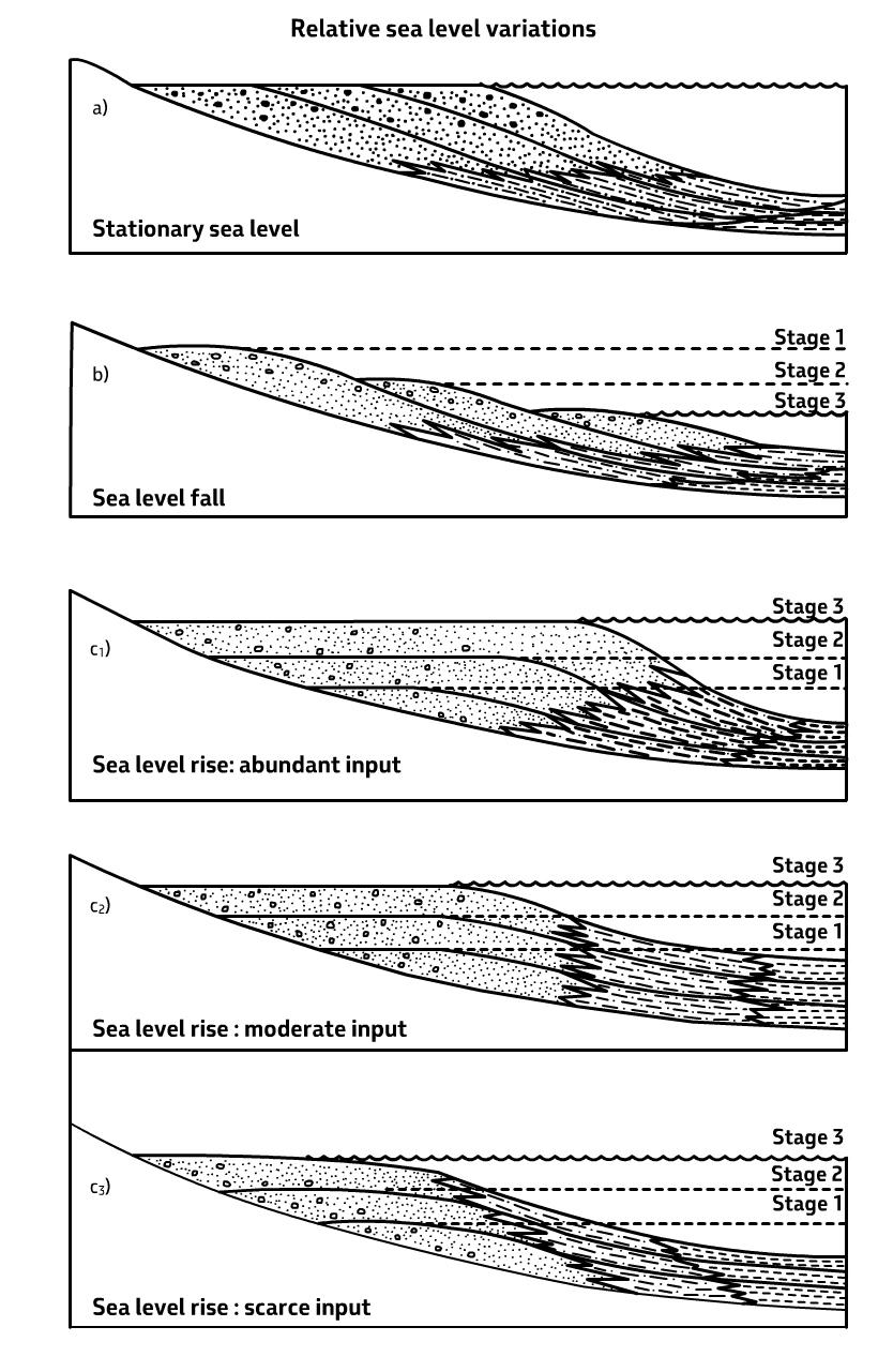
As shown in the pioneer scheme of Weller (1960), relative sea level can be stationary, falling or rising during a certain period of time (Figure 17). If sea level is stationary and enough sediment is supplied at the shoreline, the system moves seaward and is said to undergo progradation or regression. If sea level is rising, the system aggrades vertically and may develop a regressive, stationary or transgressive trend depending upon the balance between sea level rise and sediment supply. Finally, if sea level is falling, a series of downstepping and prograding wedges will form. Much of the modern sequence stratigraphic concepts are heralded in the Weller’s scheme, which quite surprisingly has been virtually ignored in subsequent literature.
Clearly, the old-school stratigrapher was concerned with a surface, whereas the Weller´s scheme emphasizes trends forming through time. Figures 18 and 19 attempt to clarify the problem of linking surfaces and trends by using the classic parasequences of the Exxon’s model (Figure 10), here simply intended as units bounded by marine flooding surfaces and whose vertical stacking results by incremental rises of relative sea level. Figure 18 shows regressive, stationary and transgressive trends of parasequencesets. Figure 19
shows how each parasequence, for instance a shallowing-upward beach deposit, records an elementary transgressive-regressive cycle, where the transgression is recorded by a surface (transgressive surface) or a thin unit through which new space is locally added (accommodation) and a regressive volume of sediment that fills it. As we will see later, the problem is somewhat more complex because of the parasequence origin and significance.
Regressions can be both depositional and erosive. Depositional regressions are sediment-driven and take place in any interval of the cycle whenever enough sediment is supplied to the system under consideration. Erosive regressions occur where rates of sea level fall exceed rates of sedimentation and the shoreline is forced to move seaward leaving behind a surface of subaerial exposure. The process forces coarse-grained marginal marine sediments to shift basinward and unconformably overlie fine-grained deposits without intervening transitional facies. This kind of regressions were termed “erosive” by Curray (1964) and Bosellini et al. (1989) and later termed “forced” regressions by Posamentier et al. (1990). These features are now considered as diagnostic of the falling stage of relative sea level.
Landward of the shelfbreak, and thus in their shelfal, nearshore and coastal and alluvial plain expression, most depositional sequences are characterized by sedimentary wedges each basically recording a transgressive-regressive cycle, somewhat similar to the cycles suggested by Embry and Joannessen (1992) and corresponding to transgressive-regressive cycles of shoreline shifts (Catuneanu, 2006). Inspection of the scheme of Figure 20, which does not include the falling stage and its related downstepping erosive regressive wedges, may clarify some concepts and terminology problems. For reasons of clarity, the scheme is based again on parasequences. Sea level rise is recorded by the vertical aggradation and onlap termination of parasequences against an unconformity surface. The scheme illustrates the basic difference between shoreline trajectories (transgressions and depositional regressions) and coastal encroachment, i.e., the progressive upstepping migration of onlap terminations of continental strata against the basal unconformity. The thickness of the cycle and the extent of its encroachment give a rough approximation of the total relative sea level rise.
CHAPTER I: General concepts TURBIDITE SYSTEMS: AN OUTCROP-BASED ANALYSIS 40
CHAPTER I: General concepts TURBIDITE SYSTEMS: AN OUTCROP-BASED ANALYSIS 41
Fig. 17 - The schemes of Weller (1960) showing stillstand, falling and rising sea-level stages, as well as prograding, stationary, and receding stacking patterns. These basic schemes have been ignored in subsequent literature.
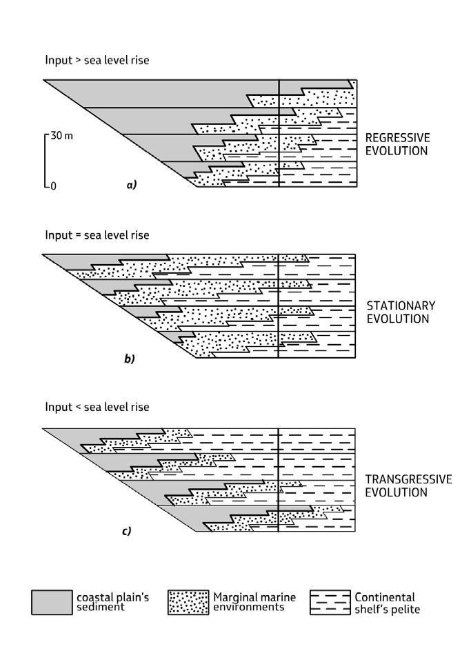
Unconformity surfaces form the boundaries of depositional sequences, whatever their scale. An unconformity is a physical surface recording a stratigraphic gap or lacuna, i.e., a missing part of geological time which is unrecorded because of non-deposition, erosion or a combination thereof. The part of the gap produced by non-deposition is referred to as hiatus, the one produced by erosion as erosional vacuity (Wheeler, 1959).
Many definitions and classifications of the various types of unconformities can be found in the literature and are not reviewed here (the interested reader is referred to Bosellini et al., 1989, and Catuneanu, 2006, among others), encompassing surfaces ranging from spectacular angular unconformities produced by structural deformation in orogenic belt basins to surfaces separating packages of conformable strata
CHAPTER I: General concepts TURBIDITE SYSTEMS: AN OUTCROP-BASED ANALYSIS 42
Fig. 18 - Regressive, stationary and transgressive trends and resulting overall shallowing-, stationary, and deepening-upward facies successions at parasequence scale (from Bosellini et al., 1989).
where the discontinuity records a gap which is impossible to document because the length of time involved is well beyond stratigraphic resolution. In its classic sequence stratigraphic definition, an unconformity is “a surface separating younger from older strata, along which there is evidence of subaerial erosional truncation (and, in some areas, correlative submarine erosion) or subaerial exposure with a significant hiatus indicated” (Posamentier et al., 1988, their p. 110; see also Mitchum, 1977). A better and more general definition, particularly for
the purposes of high-resolution studies, is probably that, whatever the hiatus, an unconformity surface simply implies a zone of subaerial exposure where accommodation is negative, passing basinward to a surface where accommodation is gradually resumed, and sedimentation thus becomes conformable and continuous. It would thus seem advisable to omit “significant hiatus” from the original definition as well as the correlation of subaerial exposure with submarine erosional surfaces, a problem still open to debate.
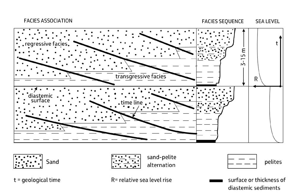
CHAPTER I: General concepts TURBIDITE SYSTEMS: AN OUTCROP-BASED ANALYSIS 43
Fig. 19 - Example of two ideal and simplified monogenic beach facies associations produced by two transgressive events, each adding new space for sedimentation, and a volume of sediment that fills this space through a shallowing-upward facies sequence, i.e., a regressive deposit. Time lines represent the beach profile at any considered time (from Bosellini et al., 1989).
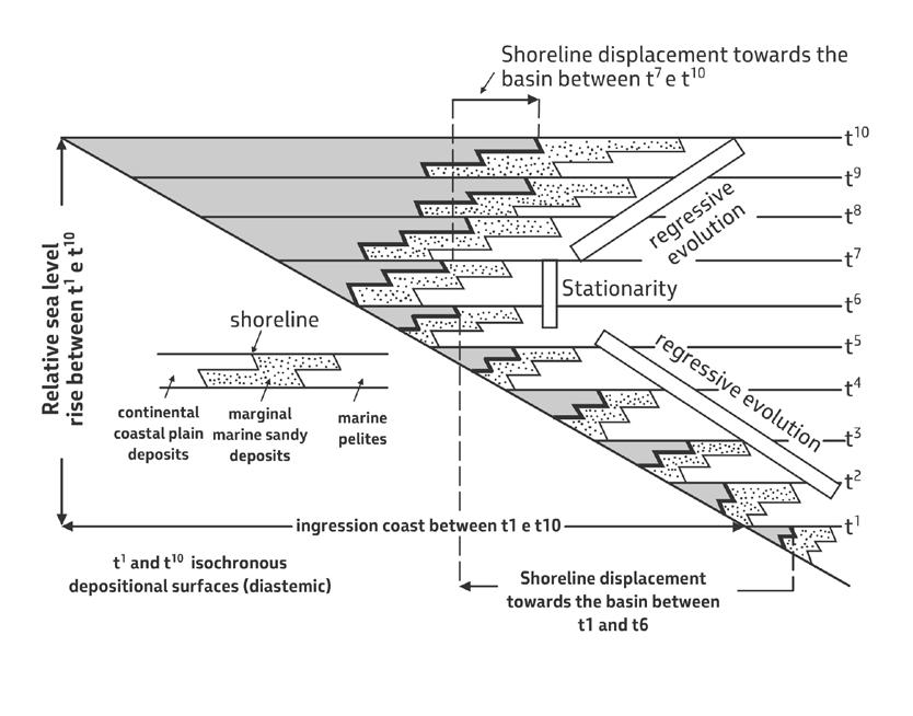
At a seismic scale, these concepts have revolutioned stratigraphy permitting to define depositional sequences as conformable successions of genetically related strata bounded by unconformities and their correlative conformities (Vail et al., 1977). At a smaller scale and particularly in high-resolution field-based studies, with which this book is primarily concerned, unconformities become increasingly more subtle and difficult to identify. At this point, facies analysis and the concept of equilibrium point become the basic tools available for their recognition (see later). Based on the above considerations, it would seem tempting to define these subtle surfaces as sedimentological unconformities
The basic meaning of an unconformity and its correlative conformity is shown in the diagram of Figure 21, inspired from Gignoux, 1950. Even more simply, these concepts become obvious if one thinks to walk down from the mountains, cross the shoreline and end its journey in the deep sea, a journey from a zone of subaerial exposure to a zone of marine dep -
osition. As a conclusion, we may say that human beings have their natural habitat upon an unconformity surface.
IV – A SIMPLE APPROACH TO INFORMALLY SUBDIVIDE STRATIGRAPHIC SUCCESSIONS
IV.1 - DEPOSITIONAL UNITS AND THEIR HIERARCHY
From a practical standpoint and thus setting aside for the moment the many conceptual and terminology problems involved, one may say that stratigraphic successions simply consist of depositional units and related bounding surfaces that are physically hierarchically ordered. In an early and preliminary attempt, Bosellini et al. (1989) proposed a practical hierarchy of these units, by these authors referred to as “stratigraphic depositional units”, that from the smallest to the largest include (Figure 22):
CHAPTER I: General concepts TURBIDITE SYSTEMS: AN OUTCROP-BASED ANALYSIS 44
Fig. 20 - An ideal transgressive-regressive cycle, showing stepwise landward and seaward migration of the shoreline during an overall relative sea-level rise. The magnitude of the rise is roughly indicated by the sediment thickness and coastal encroachment (from Bosellini et al., 1989).
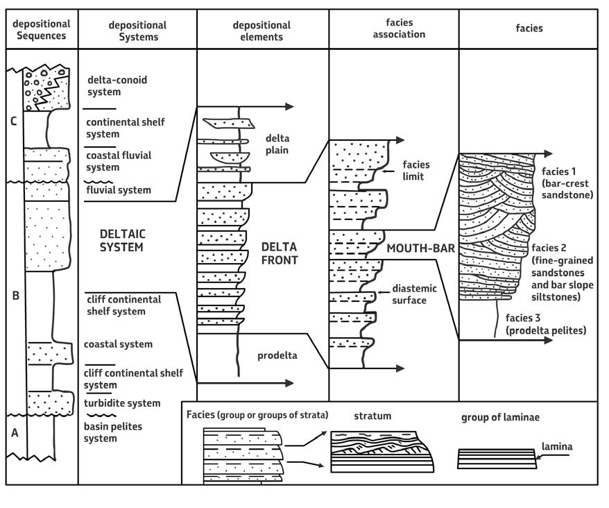
CHAPTER I: General concepts TURBIDITE SYSTEMS: AN OUTCROP-BASED ANALYSIS 45
Fig. 22 - Stratigraphic-depositional units according to Bosellini et al. (1989).
A B C 8 7 6 5 4 3 2 1
Fig. 21 - The basic scheme of an unconformity and its correlative conformity (from Bosellini et al., 1989; inspired from Gignoux, 1950, 1960). The gap or lacuna varies from A to C. In A, time 1, 2, and 3 are missing for erosion; time 4,5,6 and part of 7 is missing for non-deposition. In B, time 3 is missing for erosion; time 4, 5, and 6 are missing for non-deposition. In C, time is entirely recorded.
• Laminae
• Laminasets
• Beds
Bedsets
Facies
• Facies associations
• Depositional systems and elements
• Depositional sequences
The rationale behind the approach is simple and of practical application. Beds and bedsets stack to form facies and facies associations which allow for the recognition of depositional systems and their component elements. Depositional systems and their tracts stack to form depositional sequences. It will be noted that, with the exception of laminae, none of the units above can be reasonably understood without some basic information gathered from the smaller-scale unit that is lower in the hierarchy. Basically, these units are what stratigraphers need for facies and basin analysis. The physical hierarchy clearly implies a similarly ordered relative temporal scale.
Here, I will expand on this approach and try to refine it based on the new data and concepts gathered from my own work and selected pertinent literature. For the sake of simplicity, I will simply refer to these units as depositional units.
Depositional units can be considered as volumes of sediment ranging in scale from thin laminae up to largescale depositional sequences and surfaces vary from stratal surfaces within a bed to unconformities and their correlative conformities of depositional sequences. At a small scale, these units are relatively simple to recognize in that they are basically controlled by processes that govern the upbuilding of laminae, laminasets, beds and bedsets. These processes form bounding surfaces that are easily recognizable in most cases.
With increasing scale, depositional units become more difficult to define since processes vary with time in response to both external and internal controlling factors, such as relative sea level, climate and sediment supply variations, tectonism, or lateral shifting of the loci of deposition. This leads to changing patterns of deposition, i.e., to changes in local or regional paleogeography or paleolandscape. To fully appreciate these changes, that are recorded either by transitional conditions or more ore less distinct surfaces, one has to start looking at the way sediments stack and take into consideration time. Stacking patterns and their trends thus become very important (see Posamentier and Vail,
1988). With increasing scale, most surfaces become even more difficult to define. Most importantly, the stratal surfaces of Campbell (see above) gradually loose their strict synchroneity and become more complex surfaces usually still generally well defined in seismic reflection profiles but less obvious in outcrop analyses (see discussion in Catuneanu, 2006).
As shown in Figure 23, I believe that for practical purposes a stratigrapher should be first concerned with identifying beds and bedsets, and recognizing facies, facies associations, and facies sequences. The next step should be that of identifying depositional systems and their component elements; at the same time, the stratigrapher should organize his data and observations within the schemes of sequence stratigraphy in an attempt to understand how and why these units stack and change with time.
Applying this simple approach is not as easy as it may seem. The problem is found when one attempts to link facies to depositional systems and meets with the first and probably most genuine application of sequence stratigraphic principles to its smallest scale, that of parasequences or, better, to the stacking of facies and facies associations (see later).
Based on and expanding upon the scheme of Bosellini et al. (1989), stratigraphic depositional units can be subdivided into small-scale, medium-scale and largescale units. Small-scale units are typically observed in outcrops and cores. Medium-scale units need relatively large outcrops and long cored intervals where stacking patterns can be observed; the same units are well expressed in well logs, aerial photographs and high-resolution seismic reflection profiles. Largescale units require regional stratigraphic analyses and regional cross-sections in surface studies and are better displayed by seismic reflection profiles, especially those of regional extent.
The scheme of Figure 23 is the ideal workflow or methodology that should be followed in basin analysis. Most commonly, depending upon the purpose of the work and personal background or preferences, the flow can be interrupted at any level, and this is essentially what makes the difference between sedimentologists (small- to medium-scale units), modern stratigraphers (medium- to large-scale units), and regional geologists and explorationists (mostly large-scale units). If I am allowed a personal remark, I would say that whatever the scale of observations, everybody should have a clear perception that sedimentary geology starts with a bed and ends with a basin fill, that is, it starts with a depositional process and ends with geodynamics.
CHAPTER I: General concepts TURBIDITE SYSTEMS: AN OUTCROP-BASED ANALYSIS 46
BS B LS L
Small-scale composite depositional sequence; stacking of EDSs
Small-scale composite depositional sequence; stacking of EDSs
AG
LSCDSO
SSCDSQ
Allogroup; stacking of LSCDSQs
Large-scale composite depositional sequence; stacking of LLDSSs tracts
LLDSS
EDS SLDSS
LFa/LFs
Bedset, stacking of similar beds Bed, stacking of laminasets
Laminaset, stacking of similar laminae Lamina, the smallest observable layuer
Large-scale units. Require regional knowledge of stratigraphy and structural geology
LF Fa/Fs F
Long-lived depositional system; stacking of SLDSs
Short-lived depositional system
Lithofacies association and sequence; stacking of lithofacies
Lithofacies, stacking of monogenic, hybrid and composite facies associations
Facies association and sequenec; stacking of monogenic and hybrid facies association
Facies, stacking of similar beds
Medium-scale units. Require integration of sedimentology and sequence stratigraphy
Small-scale units. Require sedimentological background
IV.2 - SMALL-SCALE UNITS (SSUs)
IV.2.1 - Types of bed
Small-scale units are the stratal units of Campbell (1967) which, from the smallest to the largest, include laminae, laminasets, beds and bedsets. These units record processes that are essentially related to the upbuilding of layers by different types of flow, their transformations, and the complex interaction of erosion, transport and deposition. Careful analysis of these units permits to recognize the action of some basic processes such as tides, waves, mass transport, sediment gravity flows, wind, and bottom currents, thus providing a first clue to a general paleoenvironmental interpretation (see above). Caution should however be exerted since similar processes may be operative also in different environments producing similar beds. Therefore,
the analysis should be possibly integrated with the knowledge of the general context and paleontological data.
Bosellini et al. (1989) have suggested that beds can be simple or composite. Simple beds are one-event bed, i.e., a stratal unit characteristically bounded by a basal relatively sharp or erosive surface and displaying vertical grain size and lamina-set variations indicating overall waning flow conditions, though variations in the flow strength and even direction may be common. Beds of this type are “episodic” in the sense of Dott (1983, 1988) or “event beds” in the sense of Einsele et al. (1991). Turbidity currents, fluvial floods, storm waves and tsunamis are typical processes resulting in simple beds (Figure 24). Most simple beds are composed of different lithologies, most commonly by sand/mud couplets (Figure 25).
CHAPTER I: General concepts TURBIDITE SYSTEMS: AN OUTCROP-BASED ANALYSIS 47
Fig. 23 - Suggested hierarchical classification of depositional units.
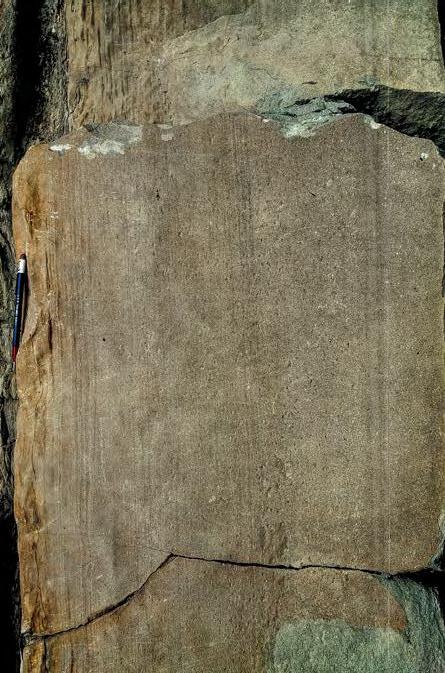
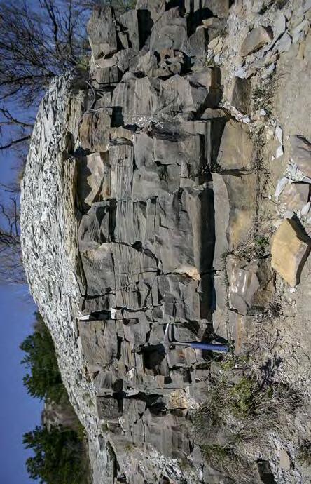
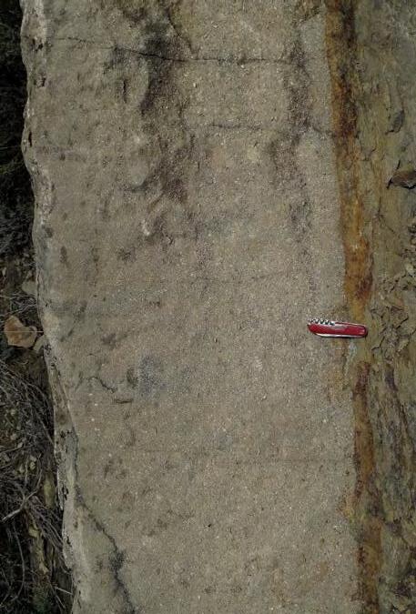
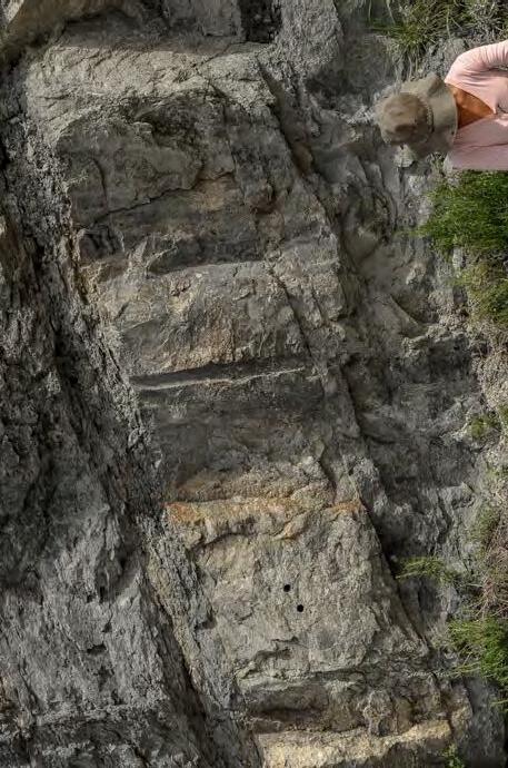
CHAPTER I: General concepts TURBIDITE SYSTEMS: AN OUTCROP-BASED ANALYSIS 48
Fig. 24
Examples of simple beds deposited by highly catastrophic events.
C D A B
A. Calcareous turbidite (“Colombina”) of the Miocene Marnoso-arenacea Fm, northern Apennines (Courtesy of Pierre Muzzi); B, C and D. tsunami beds occurring in the tide-dominated succession of the Eocene Figols Group of the Ager basin, south-central Pyrenees.
Courtesy of Pierre Muzzi
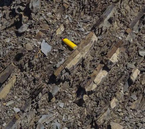
of hemipelagic origin and deposited above CCD. Eocene Hecho Group, south-central Pyrenees.
B. Thin-bedded turbidites showing complex lithologic characteristics. Turbidite beds (TB) consist of a basal fine-grained sandstone (a) overlain by a dark siltstone (b) which is capped by a light calcareous mudstone (c). The latter is overlain by a green mudstone (d) containing arenaceous foraminifera and radiolarians indicating deposition in very deep water, below CCD. Eocene Val Luretta Fm, Northern Apennines.
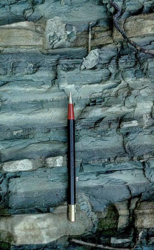
Composite beds result from the repetition of similar day-to-day processes and conditions and have thus similar lithologies and internal structures. Each composite bed is actually a bedset in which the surfaces bounding each bed are largely obscured by subsequent erosion and reworking. Composite beds are generally bounded by master bedding surfaces expressed either by erosional surfaces or thin, muddier deposits indicating periods of decreased energy. Day-to-day processes in fluvial, tidal and wave-dominated environments are typically expressed by composite beds. Figures 26 and 27 show some typical composite beds in tidal deposits. In many cases, the primary bedding is difficult to observe because of wheatering, pedogenesis or amalgamation (Figure 28).
According to Bosellini et al. (1989), beds can also be subdivided into homogeneous and non-homogenous (Figure 29). Homogenous beds are generally quite rare and con-
sist of the same lithology and grain size and are devoid of internal structures. Some mudstone beds may be (or look like) homogenous. Homogenous sandstone beds are commonly the result of syn-depositional or post-depositional dewatering and/or bioturbation. More commonly, beds are non-homogenous showing either an internal organization in terms of grain size variations (coarse-tail and distribution grading, inverse grading) and internal laminae and laminasets or an internal disorganized and chaotic structure. Beds with an internal chaotic structure include essentially mass transport units (creeping, slumps, blocky and debris flow deposits, see later).
Setting aside their lithology, texture and internal depositional structures (laminae and laminasets) that will be amply discussed in the following chapters, beds are characterized by their thickness and geometry, types of bounding surfaces, and types of accretion.
CHAPTER I: General concepts TURBIDITE SYSTEMS: AN OUTCROP-BASED ANALYSIS 49
Fig. 25 - Examples of simple beds.
A. Medium-bedded turbidites showing beds comprised by three distinct lithologic divisions including from base to top sandstone (brownish), mudstone (dark grey) and biogenic calcareous mudstone (whitish). The next sand sharply rests upon the calcareous mudstone part of which is probably
A B
a b c
d HPB TB
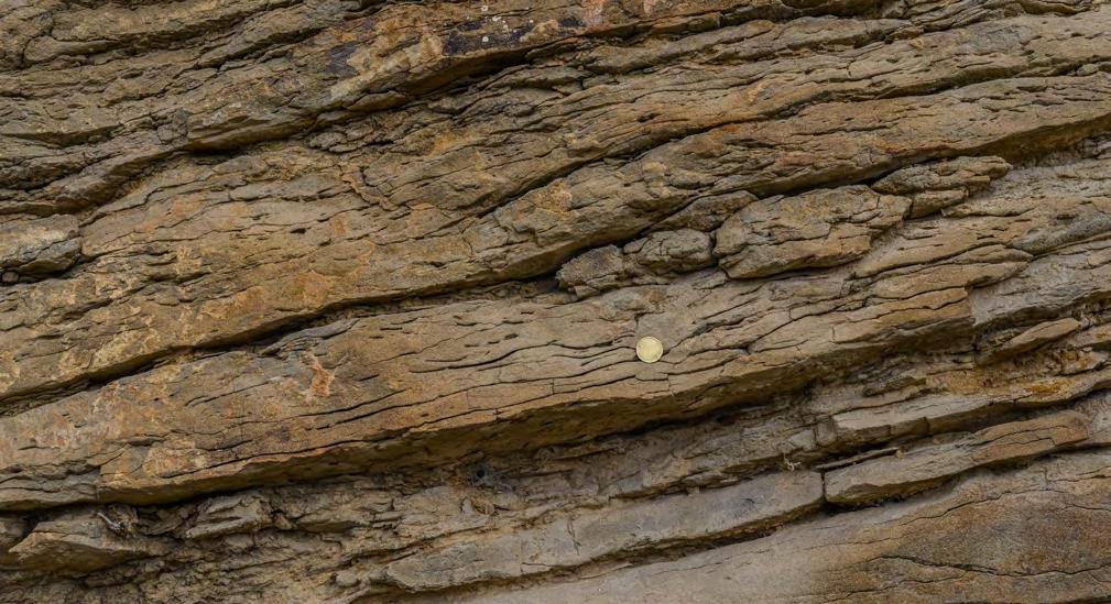
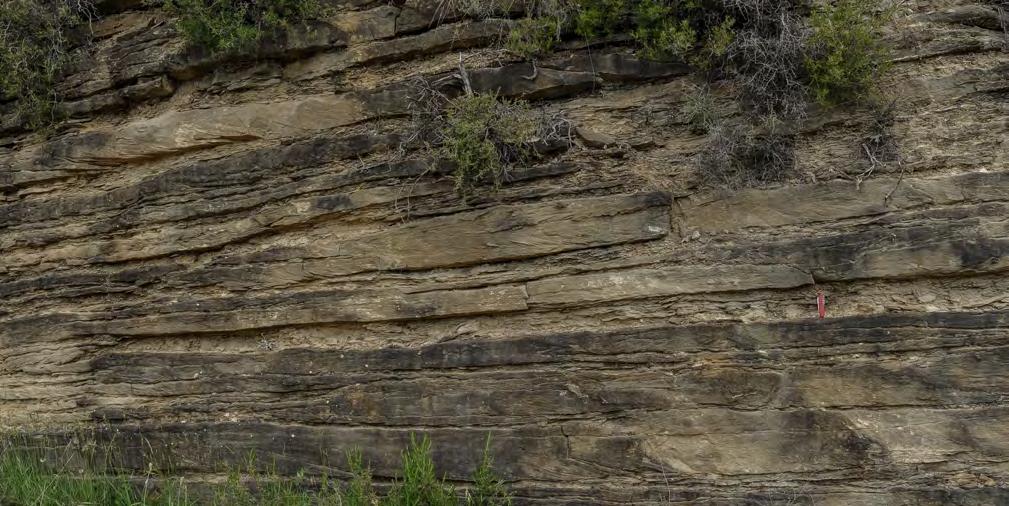
CHAPTER I: General concepts TURBIDITE SYSTEMS: AN OUTCROP-BASED ANALYSIS 50
Fig. 26 - Composite beds from tidal facies Note the abundance of flaser bedding with a typical capped-off ripple (arrow) probably indicating Intertidal conditions. Composites beds are bounded by more shaly partings that appear as the only reliable master bedding surfaces. Both examples are from the Eocene Ager basin, south-central Pyrenees Subtidal bedding made up of composite, broadly lenticular sandstone beds showing internal current reversal and some mud couplets. Also, in this case, master bedding surfaces consist of thinner-bedded and muddier partings formed during periods of weaker tidal action. Many of these beds show an internal sigmoidal pattern.
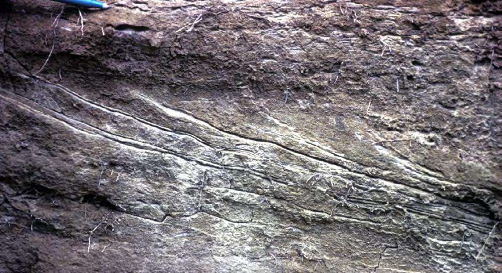
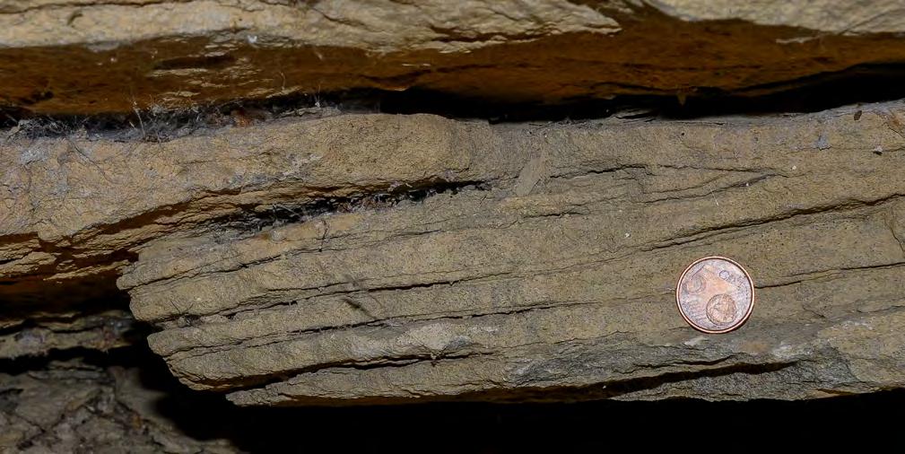
CHAPTER I: General concepts TURBIDITE SYSTEMS: AN OUTCROP-BASED ANALYSIS 51
Fig. 27 - Tidal mud couplets. Mud couplets are a very, diagnostic feature of tidal sedimentation produced by the asymmetry of the tidal cycle. The dominant flow deposits a sand layer which is markedly thicker than the layer deposited by the subordinate flow. The thinner subordinate-flow deposit is typically sandwiched between two mud drapes recording slack water conditions. Each pair sand/mud can be considered as a simple bed produced by the same flow. Mud couplets are also found in some contourite deposits. Both examples are from the Eocene Figols Group, south-central Pyrenees.
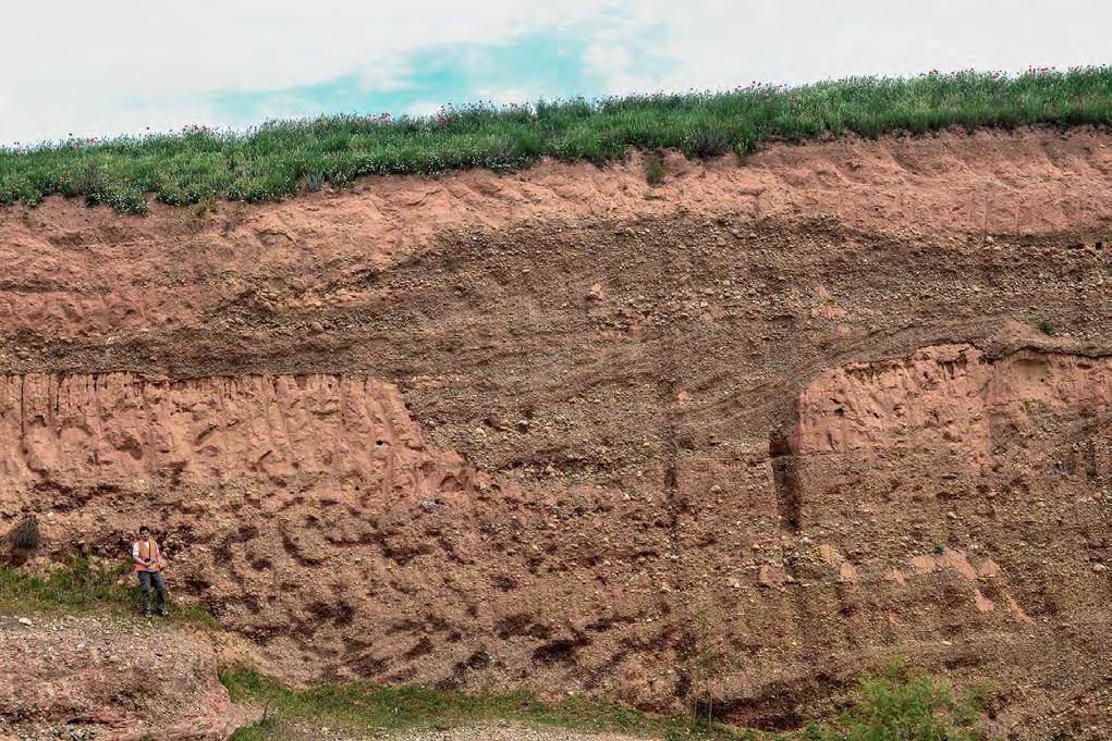


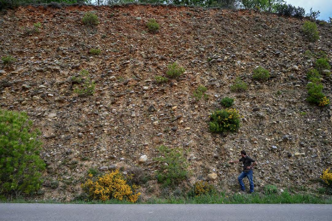
CHAPTER I: General concepts TURBIDITE SYSTEMS: AN OUTCROP-BASED ANALYSIS 52
A B
Fig. 28 - Poorly-defined and obscured bedding. Stratal surfaces poorly defined (A) and obscured (B) in coarse-grained alluvial Quaternary deposits, south-central Pyrenees. In A, channel-fill deposits, cutting into paleosols, preserve some evidence of lateral accretion (or backsets produced at hydraulic jumps). In B, debris flow conglomerates stack through vague amalgamation surfaces suggested by grainsize variations.
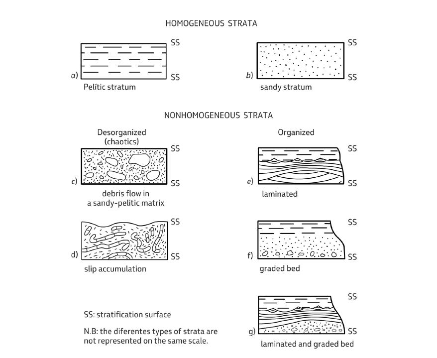
IV.2.2 - Bed thickness and geometry
Thickness may vary from mm-thick beds observed in many types of deposit (e.g., tidal-flat, prodeltaic, turbidite or contourite deposits) to huge beds reaching individual thickness in excess of 100 m, such as for example the exposed Eocene megaturbidites of the south-central Pyrenees, and many chaotic mass-transport deposits observed in both modern and ancient basins (Figures 30, 31, 32 and 33). Classifying beds based on their thick-
ness has never reached a unanimous consensus mainly because of the different opinions concerning their definition. The interested reader is referred to some basic papers dealing with the subject (e.g., Payne, 1940; McKee and Weir, 1953; Blatt et al., 1972). Figure 34 shows a suggested attempt by Campbell (1967), though I am aware that most workers would have a different opinion. If bed thickness is critical for a certain type of study, bed thickness should then be measured when logging a section in outcrop or core analysis.
CHAPTER I: General concepts TURBIDITE SYSTEMS: AN OUTCROP-BASED ANALYSIS 53
Fig. 29 - Homogeneous and non-homogeneous beds. The latter can be further subdivided into disorganized (e.g., some debris-flow deposits and slump units) and organized (e.g., grading, lamination) beds (from Bosellini et al., 1989).
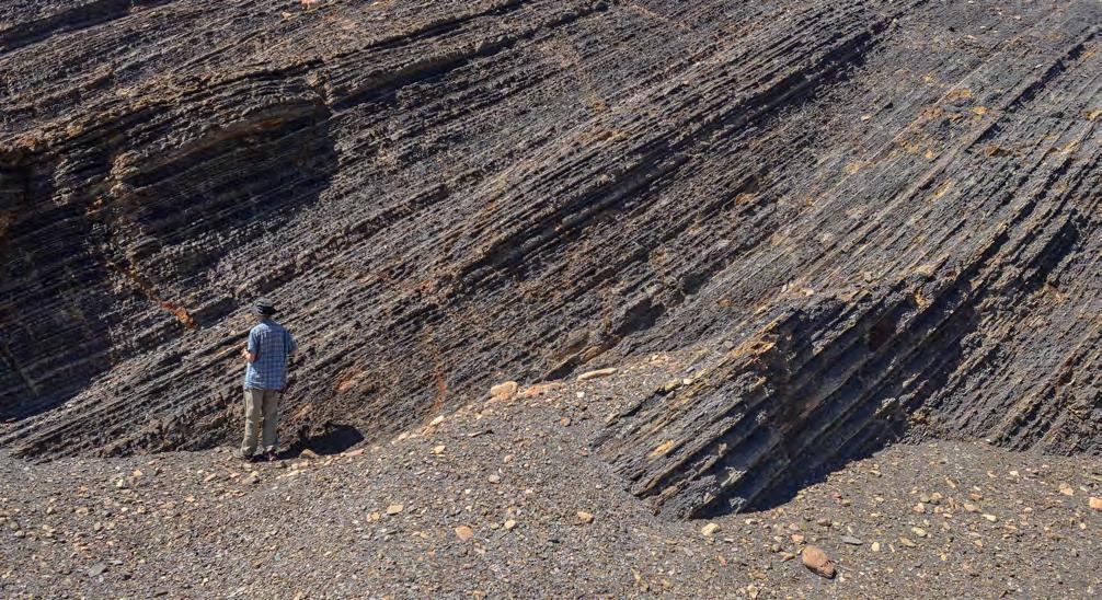
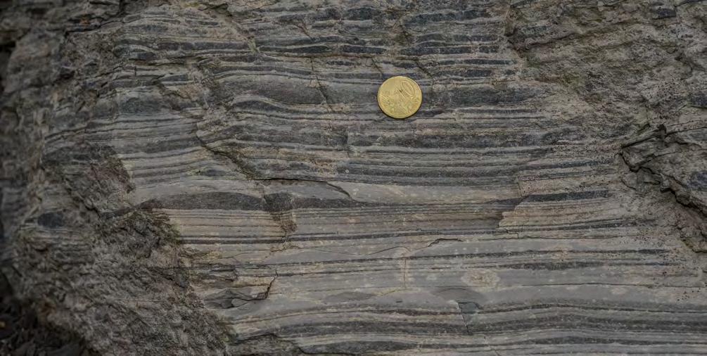
CHAPTER I: General concepts TURBIDITE SYSTEMS: AN OUTCROP-BASED ANALYSIS 54
A B
Fig. 30 - Examples of thin to very thin beds. A. Delta-slope sediments of the Jurassic Los Molles Fm, Neuquén basin, Argentina. B. Delta-slope sediments of the Eocene Castissent Group, south-central Pyrenees. Both examples can be interpreted as deposits of dilute hyperpycnal flows or river plumes (see later).
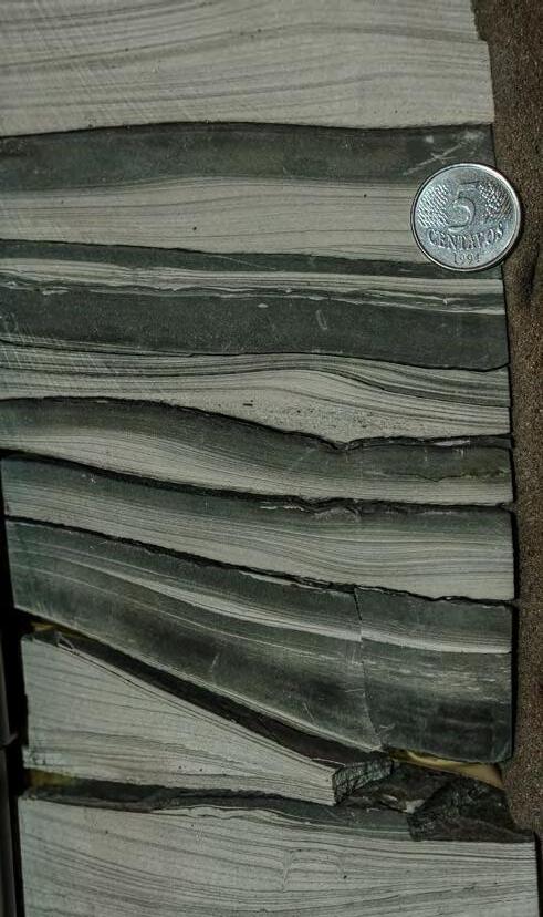
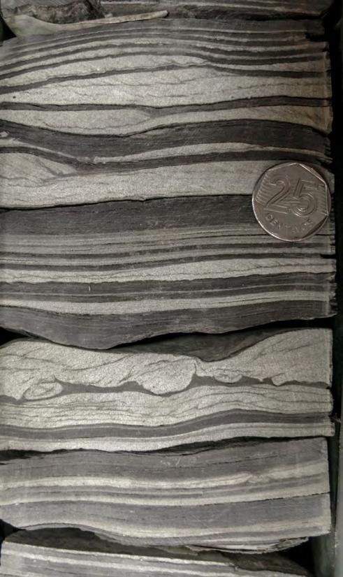
Bedding geometry is a similarly somewhat vague and probably overlooked aspect of the more general problem of layering, though, in my opinion, one of the most important. Even when driving at a reasonable speed, the most obvious features observable along road-cuts are bed thickness and geometry.
As suggested in an early attempt by Campbell (1967), the geometry of a bed is determined by its bounding
stratal surfaces (Figure 35). These surfaces can be (1) even, wavy or curved, (2) parallel or non-parallel, and (3) continuous or discontinuous. In reality, bedding geometry is considerably more complex including for instance lenticular beds, sigmoidal beds, very complex beds deposited in tidal environments, and many other types of geometry emerging from recent work in both modern and ancient deposits. Many examples of such beds are described and discussed in the next chapter.
CHAPTER I: General concepts TURBIDITE SYSTEMS: AN OUTCROP-BASED ANALYSIS 55
Fig. 31 - In cores, thin and very thin beds are much better defined as to their stratal surfaces and internal depositional structures.
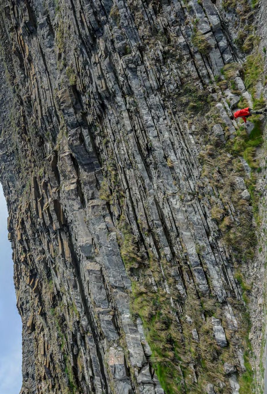
I: General concepts TURBIDITE SYSTEMS: AN OUTCROP-BASED ANALYSIS 56
CHAPTER
Fig. 32
The great variability of individual bed thickness in a turbidite succession.
Eocene Guipúzcoa Flysch, north-eastern Spain.
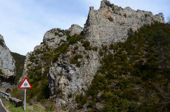
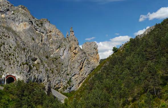
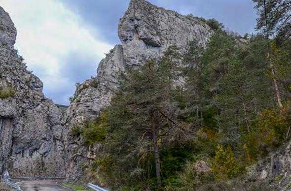
CHAPTER I: General concepts TURBIDITE SYSTEMS: AN OUTCROP-BASED ANALYSIS 57
A B C
Fig. 33 - Some features of the carbonate megaturbidites occurring in the Eocene Hecho Group, south-central Pyrenees. Thickness of individual beds may exceed 200 m; the basal divisions of many beds contain giant slabs of lithified shelfal carbonates (red arrow in C). These beds stand out as impressive relief-forming features even on satellite images and are excellent marker-beds of basinwide extent. Bedding of the megaturbidites shown in the photographs is vertical. Younging direction is toward the viewer in A and B, away from the viewer in C.
One point that should be emphasized is that beds are recognizable as long as there is a sufficient lithologic contrast along the bounding surfaces. Where the contrast is weak, the surfaces become indistinct and so does the geometry of the bed. It is therefore important, especially for beds that have some lateral extent, to consider the characteristics of the bounding surfaces that following, an energy-gradient, are seen to change from erosive, sharp to to indistinct.
IV.2.3 - Types of bed accretion
Beds generally accrete vertically (vertical accretion), i.e., following the Steno’s principle that claims that sedimentary rocks were originally deposited as horizontal strata (Figure 5). For practical purposes and for relatively limited areal extent, it can be safely assumed that beds do accrete in this way in many depositional environments and particularly in shelfal and
basin-plain regions where bedding patterns can be impressively even and parallel. The well-known stratigraphic technique of “flattening” is actually based on the Steno’s principle and assumes that horizontal bedding and vertical accretion are the norm in most sedimentary successions.
Departures from vertical accretion are found in many depositional environments and are detected with reference to originally horizontal strata. Most marginal marine sediments form seaward accreting strata because of the nearshore depositional profile at the transition between the shoreline and the shelf along the gently seaward-dipping shoreface; such a frontal accretion is typically observed in beach and some deltaic deposits. Examples of this kind of frontal accretion in marginal marine strata are shown in Figures 43 and 47. Downcurrent accretion patterns are common in sandstone bars of many fluvial and shallow-marine environments (Figure 36).
CHAPTER I: General concepts TURBIDITE SYSTEMS: AN OUTCROP-BASED ANALYSIS 58
THICKNESS IN CENTIMETERS THICKNESS IN INCHES THICKNESS IN INCHES THICKNESS IN MILLMETERS Very thick bed BEDS LAMINAE 36 12 4 1 4.0 1.0 0.39 0.12 30 30 100 100 10 10 3 3 Thick bed Medium bed Thin bed Very thin bed Very thick lamina Thick lamina Medium lamina Thin lamina
thin lamina
Fig. 34 - Attempt to classify beds and laminae according to their thickness (from Campbell, 1967).
Very
PARALLEL
EVEN
Even, parallel
WAVY CURVED
Wavy, parallel
Discontinuous, even, parallel
NON PARALLEL
Even, nonparallel
Discontinuous, even, nonparallel
Discontinuous, wavy, parallel
Wavy, nonparallel
Discontinuous, wavy, nonparallel
Curved, parallelDiscontinuous, curved, parallel
Discontinuous, curved, nonparallel Curved, nonparallel
It will be noted that, at a smaller scale, the same kind of pattern is observed in ripples; at a larger scale, seaward frontal accretion is typical of clinoforms at the shelfedge basin transition and dowcurrent accretion can be observed in huge fine-grained sediment drifts deposited by bottom currents in deep oceanic settings.
A third type of bed accretion is characteristically observed in meandering channels in fluvial, tidal and some deep-marine environments. This type of accretion, referred to as lateral accretion, was originally described from point bar deposits forming in fluvial meandering systems (Allen, 1964). As indicated in Figure 37, point bar deposits consist of cross strata that abut against a basal erosional surface and dip toward the concave or erosional bank of the meander. As we will see in subsequent chapters, spectacular examples of meandering
channels occur also in deep-water. Their lateral accretion patterns have been referred to as LAPs (lateral accretion packages) by Abreu et al. (2003).
Upcurrent- and upslope-accreting beds (upcurrent accretion) have also been reported from turbidites and fan delta-front successions and related to hydraulic jumps suffered by turbidity currents at the transition between super- and sub-critical regimes. The importance of these features, which are still poorly documented and whose origin is still matter of debates, is discussed later. The best examples of this kind of accretion are mainly derived from marine geology data from modern settings or high-resolution seismic-reflection profiles.
For the reader’s convenience, downcurrent and lateral accretion patterns of sandstone bodies are compared in Figure 38.
CHAPTER I: General concepts TURBIDITE SYSTEMS: AN OUTCROP-BASED ANALYSIS 59
Fig. 35 - Main types of bedding geometry according to Campbell (1967). Bounding surfaces can be (1) even, wavy or curved, (2) parallel or non-parallel, and (3) continuous or discontinuous.
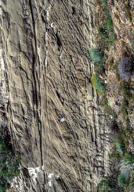
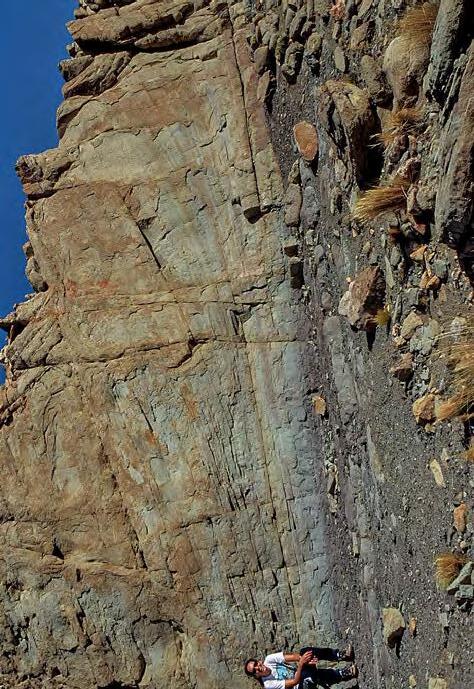
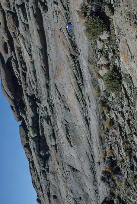
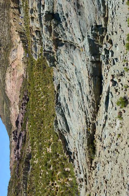
CHAPTER I: General concepts TURBIDITE SYSTEMS: AN OUTCROP-BASED ANALYSIS 60
C D A B
Fig. 36Examples of downcurrent accreting layers in tidal bars (A, B and C) and lacustrine fluvio-deltaic sediments (D).
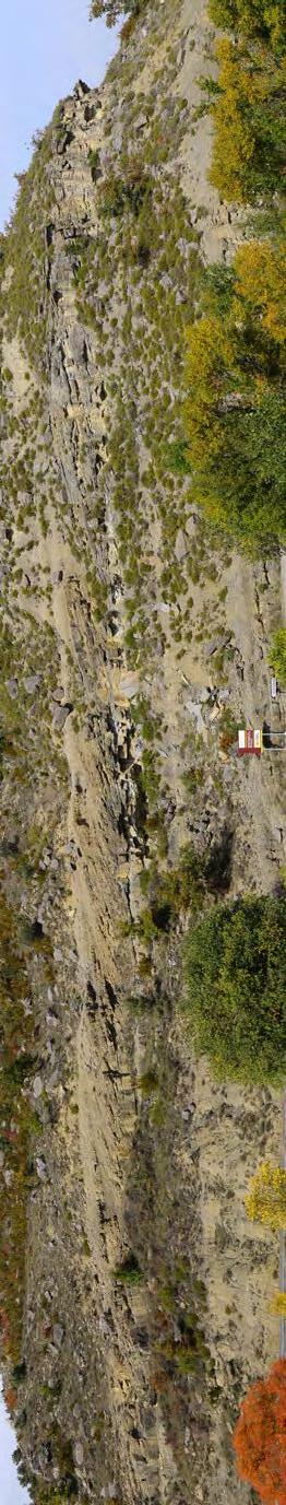
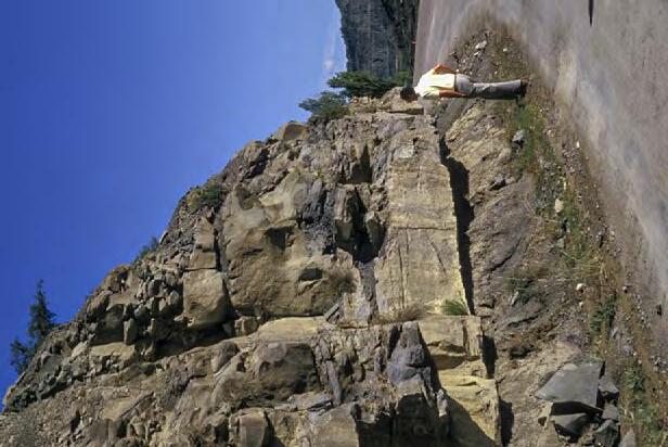
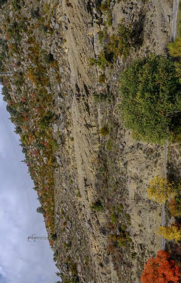
Shalying out of talweg sandstones towardmudstone of depositional bank (lateral facies change)
I: General concepts
CHAPTER
SYSTEMS: AN OUTCROP-BASED ANALYSIS 61
TURBIDITE
Fig. 37The well-known point bar of Puente de Montanana, Eocene Castigaleu Group, south-central Pyrenees (Puigdefabregas and Van Vliet, 1978; Bosellini et al., 1989): The deposit shows evidence of tidal action at its base. Note the FU facies sequence expressed by the weathering profile.
Lateral accretion surface
FU facies sequence
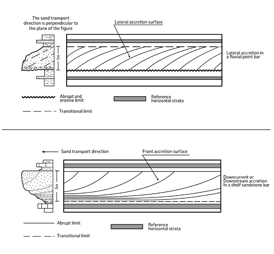
sandstone bodies. Lateral accretion patterns
both alluvial and
and accretion occurs nearly perpendicularly to flow direction. These deposits are always characterized by an erosional base produced by the migration of channel talweg and a depositional dip toward the concave bank of the meander. Each body is characterized by a typical fining-upward facies sequence. Most commonly, beds are amalgamated in the basal portion of the bar. Downcurrent accretion patterns (below) consist of bodies formed by frontal accretion of sandstone beds. As discussed in Chapter IIIA, these bodies may display a variety of internal stratal configurations and be characterized by erosional basal contacts in their upstream expression. The example shown here refers to the common expression of a sandstone bar formed, for example, in a delta-front setting. Individual beds thin and shale out in the bottom set and are generally bounded above by a sharp surface acting as local transfer zone. Typically, such bodies display thickening- and coarsening-upward facies sequences.
IV.3 - MEDIUM-SCALE UNITS (MSUs)
IV.3.1 - General
Medium-scale units can be defined as all those packages of strata where stratigraphers and sedimentologists meet with the basic problems of interpreting processes and environments of deposition and the way in which these processes and environments change in relatively short time as a result of changes in allogenic factors such as accommodation, water depth, climate and sediment flux or
authogenic factors such as the lateral shifting of the loci of deposition. Stated in more simple words, these units are the natural link between facies analysis and sequence stratigraphy. The physical scale at which these problems are considered is that of m- to dam-thick units that include facies, facies associations, facies sequences, lithofacies, lithofacies couplets, parasequences, elementary depositional sequences, and short-lived and long-lived depositional systems. An attempt is made in this section to clarify terminology and part of these problems.
CHAPTER I: General concepts TURBIDITE SYSTEMS: AN OUTCROP-BASED ANALYSIS 62
Fig. 38 - The basic differences between lateral and downcurrent accretion patterns of
(above) develop in
marine meandering channels
Though there is an increasingly tendency to extend the concept of facies down to the scale of individual beds and their component divisions particularly in turbidite deposits (see later), classic work on facies has been traditionally carried out on m-thick packages of beds. A bedset is thus also a facies in that is different from the beds above and below and is defined by the similar characteristics of its component beds. Bedsets are the natural transition between small-scale and medium-scale units. Before entering the discussion of medium-scale units, it seems necessary to briefly review the many problems involved with the use of the term “facies”.
IV.3.2 - Definition of facies
Facies – a term introduced in the geological literature nearly two centuries ago (Gressly, 1838) and which means “aspect” in Latin – is probably the term most commonly used in sedimentary geology. Unfortunately, the term is currently used in a very loose and subjective sense to define rock bodies at different level of description and interpretation and developed at many different physical scales (e.g., Moore, 1949; Krumbein and Sloss, 1958; Teichert, 1958; Blatt et al.,1972; Mutti and Ricci Lucchi, 1972; Middleton, 1973, 1978; Selley, 1978; Reading, 1978, 1996; Walker, 1984; Bosellini et al., 1989; Mutti, 1992; James and Darlymple (2010) for discussions and reviews see Walker, 1992). Facies is actually used to denote a colour (e.g., black shale facies), a lithology (e.g., a sandy facies), a general environment (e.g., a deltaic facies), a specific environment (e.g., a channel-mouth bar facies), a type of internal structure (e.g., current-laminated facies), or even a process (e.g., the “inundites” and “tempestites” of Einsele et al., 1991; also the term “turbidites”, introduced by Kuenen in 1957, belongs to this category).
The problem is in reality an old one and had already been clearly faced by Teichert (1958) who wrote (his p.2718): “This word (facies), not so long ago a generally understood and well-defined item of geological terminology, is now bereft of meaning, unless used with qualifying adjectives or accompanied by lengthy definitions”.
Following Teichert (1958), one may agree that facies is, in the last analysis, an abstraction created by a stratigrapher by considering the surn of all primary characteristics of a sedimentary rock and that the original environment of deposition of the rock is inferred from these
characteristics (facies). Since 1958, our knowledge of the origìn of primary sedimentary structures - certainly the sedimentologically most sìgnificant aspect of the ‘’lithologic characteristics” of a facies - has considerably improved, thus permitting a conceptual process of abstraction which greatly facilitates the environmental interpretation of the facies considered. A seminal paper for its clarity in this respect and the type of approach was certainly that of De Raaf et al. (1965) on the cyclic sedimentation in the Lower Westphalian of Devon, England (see also Middleton, 1978).
Considering a facies as an abstraction is obviously highly subjective since it is necessarily based on the interaction between the rock and the observer, and thus on what the observer has been taught to see, on what the observer has learnt on his own, and on how familiar the observer is with the rocks under examination. As a result, the abstraction can be very simple and objective like, for instance, “cross-bedded sandstone facies”, implying several possible processes and environments that can produce the objectively observed cross bedding. The abstraction and its environmental meaning can go a bit further by adding that the facies suggests a cross bedding produced by tidal currents. The observer can go much further, concluding that the cross bedding was produced by vigorous tidal currents on the crest of a subtidal sand ridge. At least the second level of interpretation is required for modern facies analysis. The third level of interpretation can only be attained if the observer takes into consideration also the context, that is the facies above and below and the geometry of the deposit.
Figure 39 shows an example of a cross-bedded sandstone facies from the upper Cretaceous Aren Sandstone in the south-central Pyrenees. A further consideration comes from birectional-cross bedding and some sigmoidally-shaped beds. One would be therefore tempted to conclude for a tidal origin, though the conclusion seems to be inconsistent with the lack of mudstone drapes. When viewed in their context, these cross-bedded sandstones appear to be enclosed by typical beach sandstones with seaward dipping swash lamination. The local succession also includes oyster-rich lagoonal deposits, flood tidal delta facies, and lacustrine intercalations. Summing up, the cross-bedded sandstone of Figure 39 can be reasonably interpreted as the remnant of a tidal inlet within a barrier-island environment. Strong wave energy is the possible explanation for the lack of mud drapes.
CHAPTER I: General concepts TURBIDITE SYSTEMS: AN OUTCROP-BASED ANALYSIS 63
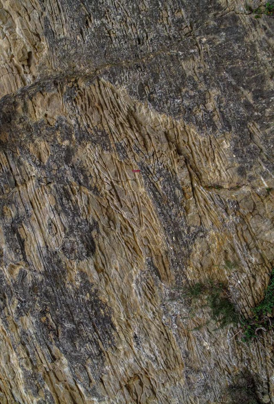
and its interpretation as a tidal inlet deposit upon framing the exposure within its context. See text for explanation. Upper Cretaceous Aren Sandstone, near
-
General concepts
SYSTEMS: AN OUTCROP-BASED ANALYSIS 64
CHAPTER I:
TURBIDITE
Fig. 39
Cross-bedded sandstone facies
Tremp, south-central Pyrenees.
Beach swash zone
Tidal inlet cross-bedded Sandstone facies
IV.3.3 - Sedimentological facies
In sedimentological studies, the term is commonly used to define the physical characteristics of a rock which are related to specific processes and ultimately to an environment of deposition. Since the basic approach to this kind of study is sedimentological, the term sedimentological facies seems very appropriate.
For the sake of clarity, we follow herein Bosellini et al. (1989) who used the term in a descriptive way and assigned it an environmental significance only if framed within the context of vertical and lateral facies associations (see later). A facies considered in isolation only gives information about sedimentary processes mainly derived from primary sedimentary structures (laminae and laminatsets) observed within individual beds. Such processes, as it has been clearly recognized in recent years, can operate in many different depositional environments and can not therefore be diagnostic of any specific depositional environment. One-event graded beds, for instance, can be observed in alluvial, nearshore, and deep-water strata as the result of floods, storms or turbidity currents. Such beds can be interpreted correctly only if viewed within the context of their facies association.
For our purposes and with specific reference to terrigenous rocks, a facies can be considered as a bedset with individual thickness ranging between tens of decimeters and a few tens of meters. Most commonly, facies are expressed by bedsets developed on a meter scale. Each facies possess distinctive characteristics that permit to differentiate it from the facies above and below and from those which are adjacent to it.
Individual facies have geometry and areal extent which depend upon the configuration and extent of the original environment where the considered unit formed. The external geometry of a facies can be viewed in terms of extent to thickness ratio. For practical purposes, this ratio is more commonly expressed by the width to thickness ratio. Facies and related facies associations thus form a spectrum of deposits having a highly variable geometry (see later). All the different ways to study and try to understand facies are generally lumped together with the term facies analysis
At the scale of bedsets, a facies is defined by (1) the characteristics of its component stratal units, (2) its external geometry, and (3) types of boundaries. A great deal of care should be exerted in defining both vertical and lateral facies boundaries. These boundaries can be transitional, sharp, or erosional. Depending upon the
correct recognition of these boundaries, a facies can be considered as genetically related or unrelated to the facies that enclose it. As a general rule (although it is not always the case), transitional boundaries indicate genetic relations, i.e., stratigraphic continuity, whereas sharp and/or erosional boundaries are in some cases associated with more or less important changes and/or breaks in sedimentation, thus indicating lack of direct genetic relations.
The characteristics of the component stratal units, including texture, bedding pattern, internal sedimentary structures, fossil assemblages, and traces of organic activity (burrows, root prints, etc.) generally permit the interpretation of each facies in terms of specific depositional processes and, though with some guessing, a general depositional environment. The latter, however, is commonly better inferred from facies associations and facies sequences (see below).
IV.3.4 - Facies sequences and facies associations
A facies sequence is represented by the vertical stacking of two or more facies which are gradational into each other and have thus been deposited in stratigraphic continuity. Depending upon many factors, but mostly on the types of process, environment and sediment availability, facies sequences may be stationary or showing coarsening- and thickening-upward (CU) or fining- and thinning-upward (FU) trends (Figure 40 A). A classic CU trend is developed for instance by a prograding beach; a FU trend is typical of laterally accreting point bars developed in a meandering channel as well as in many other environments, both alluvial and marine. As discussed later, these trends have to be treated with great caution because of the many possible pitfalls. The three-dimensional assemblage of these facies makes up a facies association. Essentially a facies association is a facies tract that can be stationary, prograding or receding (Figure 40 A).
Facies sequences have commonly thickness of several meters up to a few tens of meters. The areal extent of individual facies and facies associations depends upon the original extent of the environment where these units formed. Sand and gravel deposited at a mouth of a small torrential stream in an ephemeral lake may form a facies association extending only over a few tens of square meters; some turbidite facies extend over distances up to hundreds and even thousands of km.
CHAPTER I: General concepts TURBIDITE SYSTEMS: AN OUTCROP-BASED ANALYSIS 65
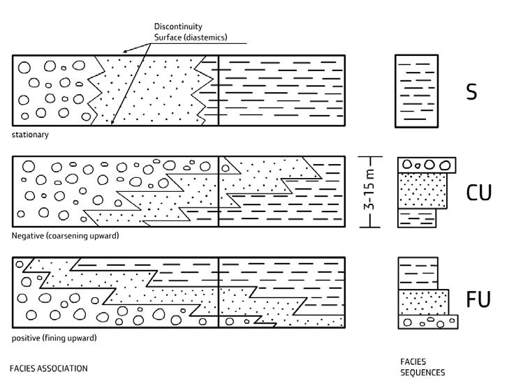
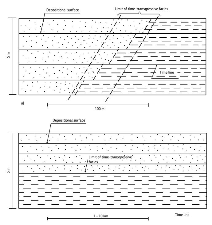
CHAPTER I: General concepts TURBIDITE SYSTEMS: AN OUTCROP-BASED ANALYSIS 66
A B
Fig. 40 - A. Stationary (S), prograding (CU) and receding facies (FU) associations and related vertical sequences (current direction is from left to right). B. Time-transgressive and time-parallel facies boundaries.
If the relations between superimposed and adjacent facies are recognized as indicative of stratigraphic continuity, then the resulting facies associations can be interpreted as the product of a specific depositional environment. The approach to this interpretation requires being familiar with at least the basic principles of sedimentology and particularly the origin of primary sedimentary structures, both erosional and depositional, and, most importantly, being also familiar with what happens in modern environments (see later).
IV.3.5 - Facies and environment of deposition
Once the main process or processes which is or are responsible for each facies has or have been determined, then a facies association or its corresponding facies sequence can be viewed as the sedimentary product of genetically related processes which were operative in a specific environment of deposition. The concept behind this interpretation is the classic Walther’s principle, or law (Walther, 1983), which states that only those facies that are seen form adjacent to each other in modern environments can be superimposed in stratigraphic continuity (Figures 42 and 43), a principle that holds true also at a larger scale. The principle implies that each environment can be subdivided into geographically distinct subenvironments each of which is characterized by specific erosional and depositional processes, and therefore by a specific facies (the “lithotope” of Krumbein and Sloss, 1951). The local processes of a subenvironment are genetically inter-related being part of the main process or processes that defines or define the environment where the facies association is forming. Energy gradients defining specific subenvironments are obvious in most modern environments we are familiar with, such as beaches, tidal flats, channel-mouth bars, and many others. A facies is thus ultimately the product of a specific subenvironment and a facies association is made up of those facies that form in the component subenvironments of a specific environment. Facies sequences have been erected as facies models for a number of environments (see especially the various editions of the “Facies Models” of the Geological Association of Canada and the “Sedimentary environments” edited by H.G. Readings, 1978, 1996) and these models have become very popular as a useful guide among sedimentologists. It will be noted that the Walther’s law heavily relies on modern environments, being thus based on the saying “the present
is the key to the past”. As discussed later, the concept should admit some serious departures, but it remains of fundamental importance for the interpretation of many alluvial and shallow-marine deposits. Figures 44 and 45 show some simple and obvious applications of it. Figures 46 and 47 illustrate examples of how processes and physiography of modern environments can be used to define facies models for ancient deposits. The ideal deposits to understand the concepts discussed above are in particular the marginal-marine strata formed in beach, tidal and deltaic environments because of their very distinctive facies characteristics and relatively well-understood processes. Although still valid, the same concepts are less clear or have been overlooked in other environments and particularly in deep-water settings (see later).
IV.3.6 - Time-parallel and time-transgressive facies boundaries
Depending upon the type of deposit, facies boundaries can be time-parallel over great distances, or time-transgressive, as in most marginal marine deposits (Figure 40 B). A spectacular example of time-transgressive facies boundaries in a mouth-bar deposit from the Eocene Figols Group, south-central Pyrenees, is shown in Figure 41 A. The example also provides a clear demonstration of the validity of the Walter’s principle at outcrop scale. Impressive time-parallel facies boundaries can be observed in shelfal and basinal settings. In the latter, some turbidite sandstone lobes (essentially bedsets) can be traced for tens of km (Figure 41 B).
IV.3.7 - Sedimentological facies and stratigraphy
Most of the concepts discussed above refer to those cases in which a facies association is built up by the same process. Such facies associations can be termed monogenic facies associations because essentially related to a single process or hybrid facies associations when showing minor modifications produced by a subordinate process. These facies associations have no specific sequence stratigraphic significance and simply record the only way in which a sedimentary environment can be recorded by a deposit within its available space during periods of time sufficiently short so that changes in accommodation can be considered as negligible.
CHAPTER I: General concepts TURBIDITE SYSTEMS: AN OUTCROP-BASED ANALYSIS 67
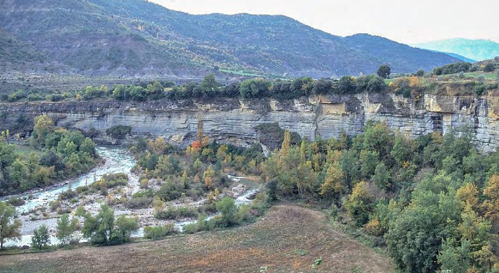
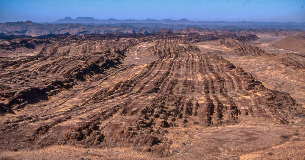
2,
the
over short distance.
Facies 1, more
CHAPTER I: General concepts TURBIDITE SYSTEMS: AN OUTCROP-BASED ANALYSIS 68
A B 2 1
Fig. 41 - A. Time-transgressive facies boundaries The example shows a mouth-bar deposit from the Eocene Figols Group, south-central Pyrenees, in the Rio Isabena valley. The strata are gently dipping seaward and the succession is sharply overlain by a marine flooding surface (see Figure 43 for a more dip-oriented view). The example shows that the two facies (1 below and 2 above) are lateral equivalent as demonstrated by bedding surfaces (time surfaces) that can be traced all across
exposure.
proximal, passes laterally (seaward) into facies
giving way to a time-transgressive facies boundary
B. Time-parallel facies boundaries The late Proterozoic Zerrissene Turbidite System, desert of Namibia. Note m-thick sandstone packages (turbidite sandstone lobes) with perfect tabular geometry that can be traced for many tens of kilometers. Bedding surfaces (time surfaces) coincide with time-parallel facies boundaries.
As clearly seen in modern environments, monogenic (and hybrid) facies associations and sequences are very short-lived sedimentological features. Typical examples of such features are the classical fining-upward facies sequences that we can see forming today in meandering fluvial channels or the coarsening-upward facies sequences produced by frontal accretion of modern channel-mouth bars or beaches. Such features can clearly occur anywhere and anytime during a cycle of relative sea-level variation provided that suitable conditions exist for their formation. Many sedimentological facies models describe features of this type (see above).
Monogenic (and hybrid) facies associations, each recording the same type of environment, can be laterally associated to form more complex bodies of similar consanguineous facies associations or grade into different types of facies and related environments that were originally adjacent. Such settings can be viewed as tracts of monogenic facies associations
(Figure 48). Within a given accommodation space, which is assumed to remain roughly constant during deposition (see later), similar monogenic (and hybrid) facies associations and related sequences may stack to form composite monogenic facies associations . This repetitive stacking pattern is the expression of the classic autocyclic process of Beerbower (1964) and is essentially related to the freedom of a depositional system to switch laterally its depositional zones within its assigned accommodation space. Bifurcation and avulsion of distributary channels and ensuing relocation of mouth-bar deposition in a fluvial-dominated delta system are a typical expression of this process. The same process is also common in turbidite systems in their channel-lobe transition and proximal lobe zones zone, giving way to complex architectures produced by both erosion and compensation (see later). The boundaries between these monogenic facies associations can be either erosional or transitional.

CHAPTER I: General concepts TURBIDITE SYSTEMS: AN OUTCROP-BASED ANALYSIS 69
Fig. 42 - Scale-invariant space-time relationships in strata deposited in stratigraphic continuity (i.e., vertical and lateral stratigraphic relationships).
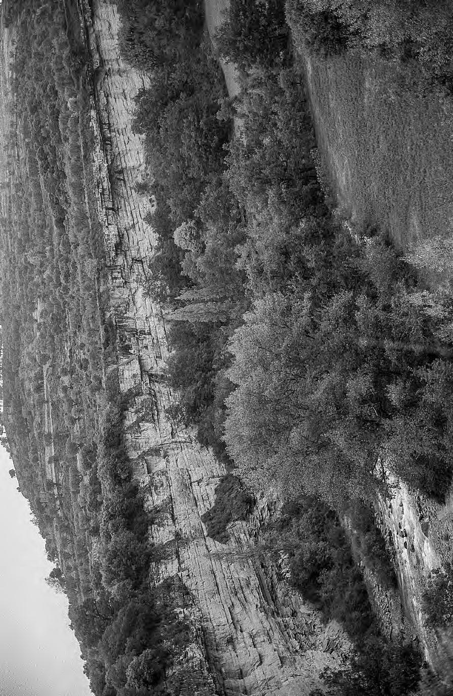
The Walter principle as illustrated by time-transgressive deltaic deposits. Red lines indicate gently seaward-dipping bedding surfaces along which a coarser-grained and thicker-bedded sandstone facies grades into more parallel-sided and finer-grained facies. The two facies stack vertically forming CU sequences characterized by stratigraphic continuity and can be said to be “genetically related”. Eocene Figols
Isabena valley, south-central Pyrenees (see also Figure 41).
CHAPTER I: General concepts TURBIDITE SYSTEMS: AN OUTCROP-BASED ANALYSIS 70
Fig. 43
Group,
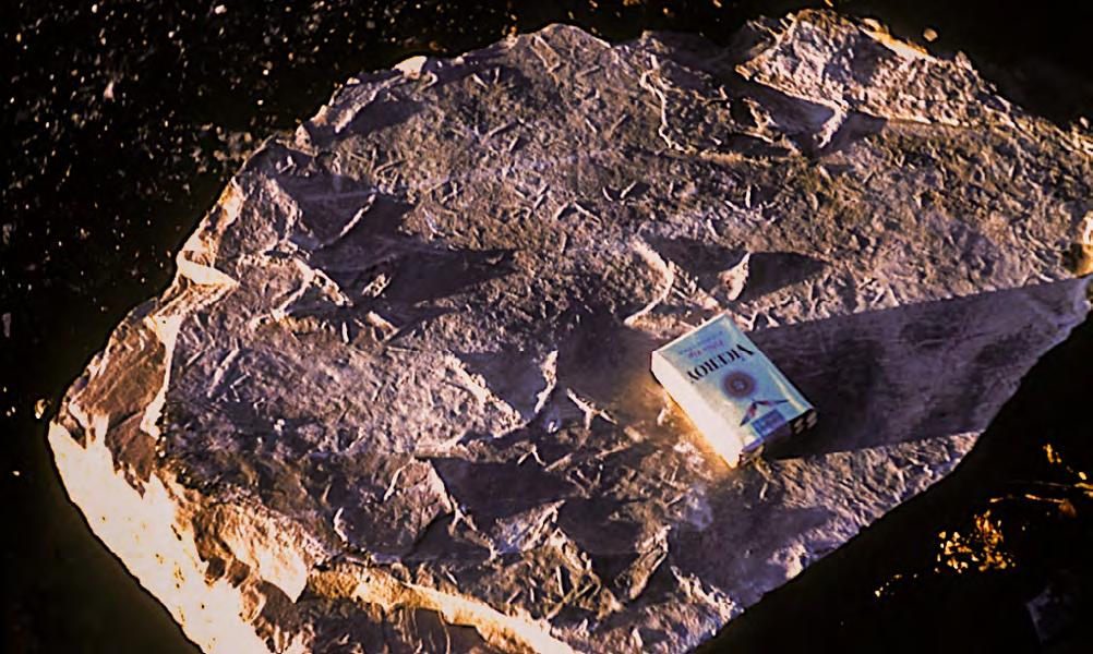
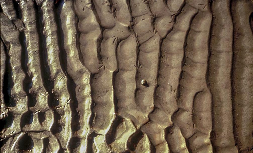
CHAPTER I: General concepts TURBIDITE SYSTEMS: AN OUTCROP-BASED ANALYSIS 71
A B
Fig. 44 - “The present is the key to the past” A. The well-known Oligocene “pattes d’oiseaux” of Mangin (1962) from the Liedena Beds, southcentral Pyrenees. These tracks are preserved as casts at the base of flood-generated sandstone beds in a coastal plain environment. B. Small bird tracks in a modern stream. Water depth is indicated by the floating leave.
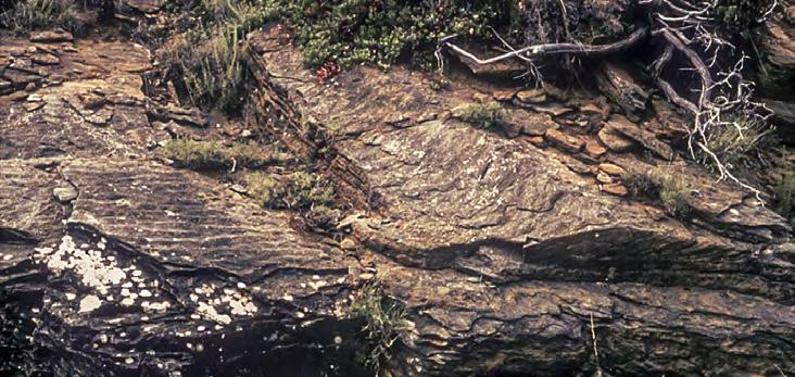
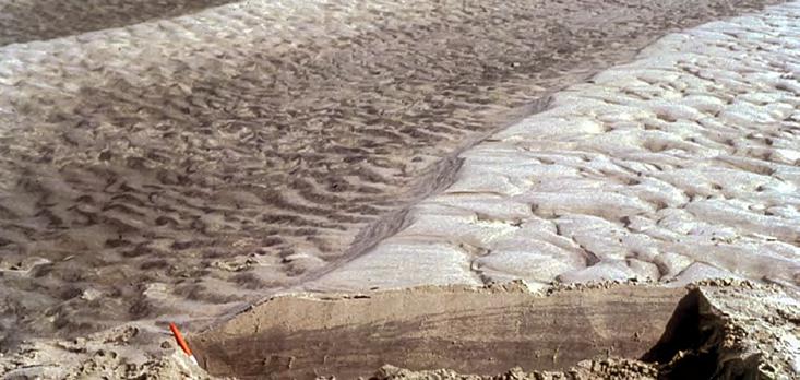
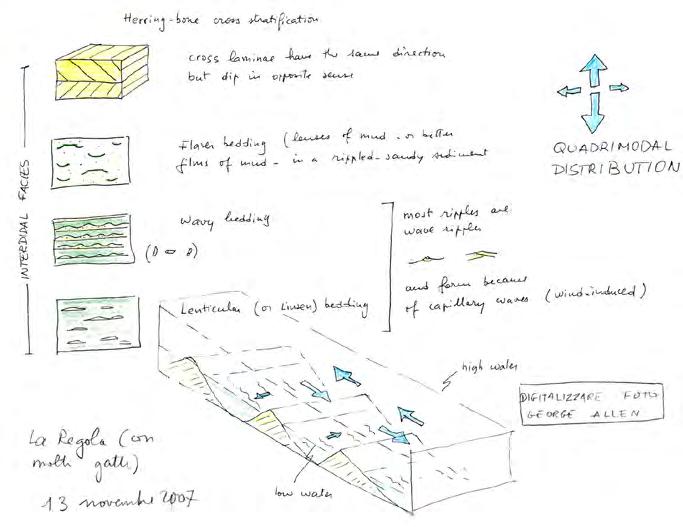
CHAPTER I: General concepts TURBIDITE SYSTEMS: AN OUTCROP-BASED ANALYSIS 72 A B A B
Fig. 45 - Interpretation of an ancient sandstone facies as an intertidal or shallow-subtidal deposit based on what can be observed in a modern tidal flat (Arcachon Bay, France). The ancient example is from the upper Cretaceous Aren Sandstone, south-central Pyrenees.
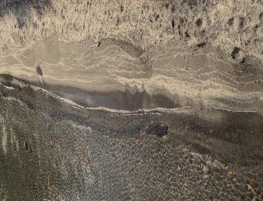
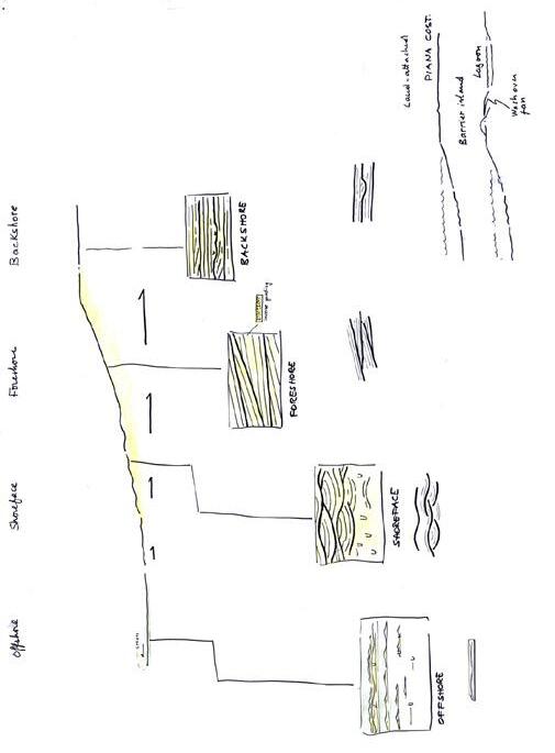
Fig. 46A simple example of how a modern environment can be used to understand a facies association in ancient successions. The small beach on the right is from a lake in the San Martin region, Argentina, and was photographed in fair-weather conditions. For this reason, the shoreface is characterized by small-scale wave ripples. Occasional storm waves are recorded by coarse sediment cast on the backshore. The sketch on the left shows a more general facies association with medium-scale wave ripples being formed in the shoreface (in high-energy beaches through cross stratification related to longshore currents and modified by wave action can be present). Thin storm beds commonly occur more seaward, at the transition with offshore mudstones. The thick lines indicate master bedding surfaces formed when the beach profile is modified by storms.
CHAPTER I: General concepts TURBIDITE SYSTEMS: AN OUTCROP-BASED ANALYSIS 73
Shoreface
Foreshore
Backshore
Marinefloodingsurface
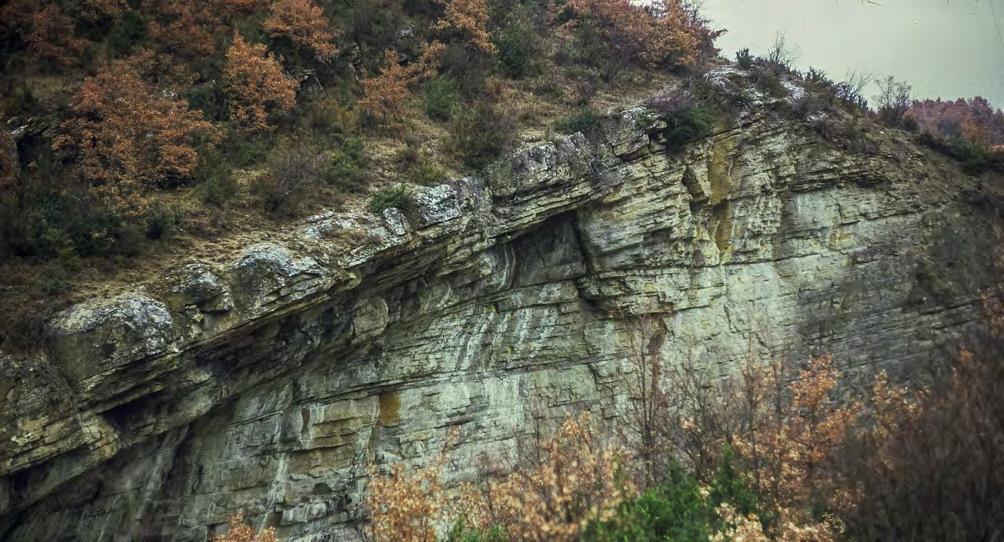
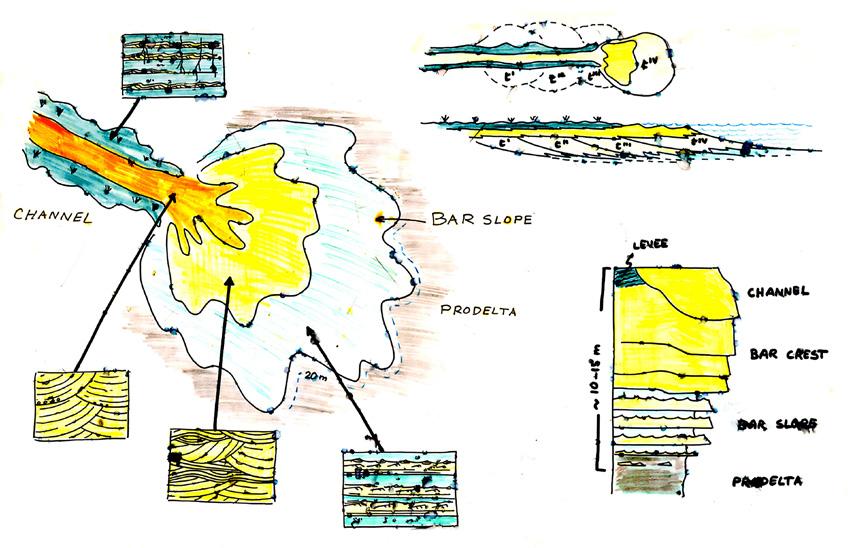
CHAPTER I: General concepts TURBIDITE SYSTEMS: AN OUTCROP-BASED ANALYSIS 74
Fig. 47 - Example of an ancient sandstone body interpreted as a prograding river mouth-bar on the basis of its facies characteristics, stratal geometry and comparison with a modern channel-mouth bar environment. Eocene Atarès Fm, south-central Pyrenees.
Bar slope
Prodelta
Barcrest
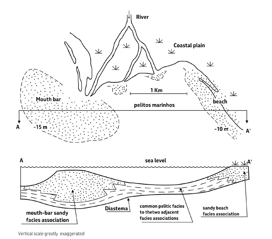
Though fundamental for understanding processes and environments, facies analysis remains essentially a sedimentological approach and the different stratal units that the analysis permits to recognize are not, in most cases, operational units for stratigraphic analysis. Unless the work is carried out in great detail and at a very local scale, sedimentological facies and their associations cannot be generally mapped or used for preparing stratigraphic cross-sections of broader scope. Nonetheless, the results of facies analysis permit to delineate processes and environment of deposition and, therefore, introduce the problem of depositional systems and their component elements, thus allowing for moving higher into the hierarchy of depositional units.
IV.3.8 - Lithofacies, lithofacies sequences and lithofacies associations
Exposed terrigenous successions are characterized by the cyclic alternation of ledge-forming m-thick (less commonly dam-thick) units of relatively coarsegrained sediment with units of variable thickness consisting of finer-grained lithologies. An excellent example of these units is shown in Figure 49, depicting a succession of lens-shaped conglomerates separated by finer-grained lithologies and recording the stacking of alluvial fans entering flood basins with some ephemeral lacustrine episodes.
These units are each characterized by a distinctive predominant lithology and thus differ from the units
CHAPTER I: General concepts TURBIDITE SYSTEMS: AN OUTCROP-BASED ANALYSIS 75
Fig. 48 - Tract of monogenic facies associations having in common a mudstone facies.
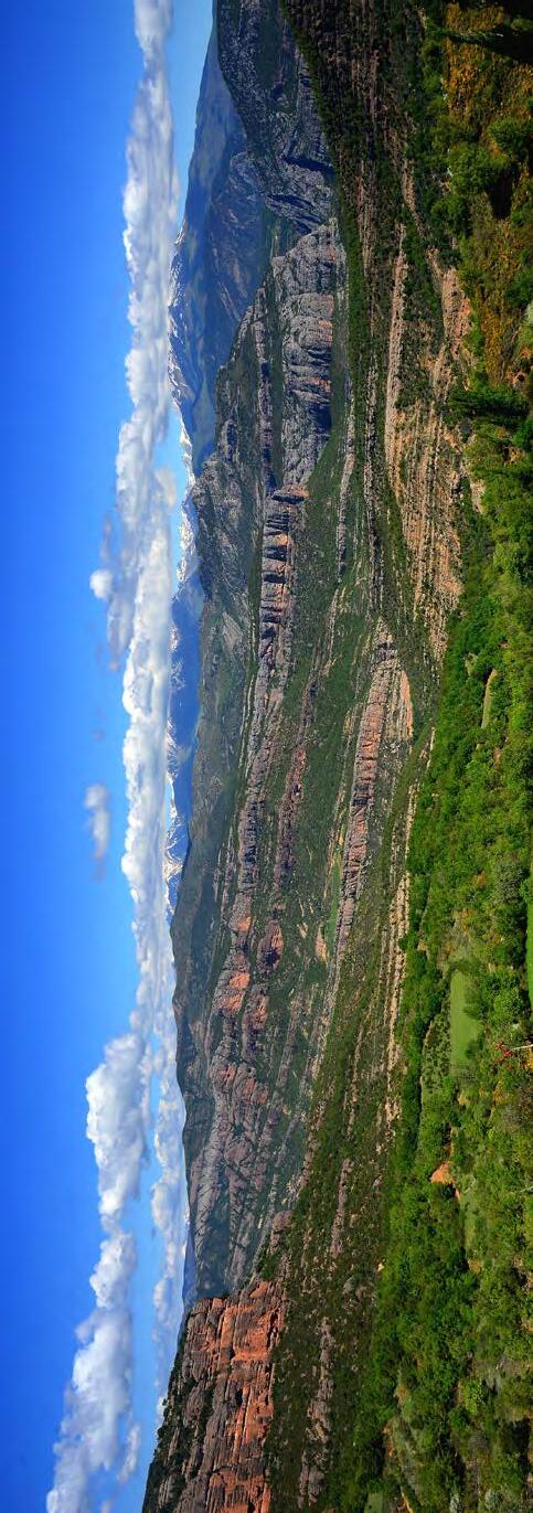
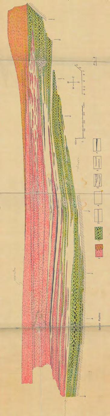
Eocene and Oligocene conglomerates
formed by alluvial fans unconformably resting upon Cretaceous carbonates and older rocks (in the background) after a major phase of deformation and uplift of the Pyrenees and infilling a structural depression. The alluvial fans form a long-lived alluvial fan system made up by the stacking of short-lived systems as clearly shown in the schematic cross-section below. Sediment transport was primarily toward the viewer. Red fans, pinching-out to the right, are derived from Permo-Triassic rocks; green fans, pinching-out to the left, were derived from Cretaceous carbonates. The thick green fan in the lower left, was derived from the opposite side of the basin. Note how green fans recede with time letting red fans spread out to the right Flood-plain mudstones and sandstones, as well as ephemeral lakes with local development of small fluvio-deltaic systems and lignite-bearing units (black) are in light color. Near Pobla de Segur, north of Tremp, south-central Pyrenees.
CHAPTER I: General concepts TURBIDITE SYSTEMS: AN OUTCROP-BASED ANALYSIS 76
Fig. 49Spectacular exposure of upper
Courtesy of Sergio Robles and Joan Rosell (early 80’s)
above and below and laterally adjacent. For the sake of simplicity and convenience, let’s consider m-thick sandstone bodies alternating with dominantly mudstone units. These units, or lithofacies, are probably the most obvious, objective and natural subdivisions that we can make in sedimentary successions wherever a sufficient lithologic contrast permits their recognition (Mutti et al., 1994). They are directly observable in outcrops and, if sufficiently thick, in aerial photographs, as well as clearly expressed on wireline logs and most high-resolution seismic reflection profiles. Most detailed stratigraphic cross-sections in both surface and subsurface studies are based on these units which are in most cases the smallest and informal operational unit of stratigraphic analysis. Needless to say, the sandstone units are the “potential” reservoirs of the oil industry. Physical and temporal scale of these units coincide with the parasequence scale of sequence stratigraphy. The vertical association of a coarsegrained lower unit with an overlying finer-grained unit is herein referred to as a lithofacies sequence (Figure 50) and its three-dimensional expression as a lithofacies association
As we will see later, this cyclic alternation can be observed in alluvial, shallow-marine and deep-marine settings, though with some obvious differences. In a way, one can say that this cyclicity is the background motif of most sedimentary successions (Figure 51). However, for reasons of clarity, I will expand here on these units making specific reference to shallow-marine settings where many problems are considerably clearer.
From a sedimentological standpoint, lithofacies can be seen as lithologically similar facies associations that permit their paleoenvironmental interpretation. Most of the information is derived from the study of sandy lithofacies which contain an abundance of sedimentary structures relatively easy to understand. Conversely, mudstone-dominated lithofacies are generally more difficult to interpret in outcrop studies because are commonly poorly exposed. However, where the exposures are good also these lithofacies may contain abundant sedimentological information expressed, in most cases, by alternating thin sandstone and mudstone beds. Unfortunately, these alternations are commonly overlooked and simply referred to as “heterolithic facies” in most recent literature, a term traditionally used to define a specific tidal flat deposit (Reineck and Wunderlich, 1968) and now used to collectively define
thin sandstone and mudstone alternations, whatever their origin. These facies are extremely well expressed in cores, thus greatly facilitating the interpretation of processes and environments (see Figure 31).
Sandy lithofacies differ from the lithologically similar facies associations discussed above in that they are characterized by a more complex internal organization as well as, in some instances, by a slightly greater thickness. In some cases, they do not differ at all, being made up by simple, composite or consanguineous monogenic facies associations through their entire thickness. Most commonly. however, they differ in showing a more or less clear tendency to develop vertical trends indicating that the basic processes controlling deposition change gradually or abruptly with time. For instance, tides or wave action may become predominant with time at the expenses of fluvial processes in delta-front deposits; in other cases, carbonate deposition may replace terrigenous sedimentation. In deep-water, bottom-current deposits may overlie turbidite sandstone beds within the same sandstone body. These deposits are essentially composite facies associations in which genetically distinct processes partake the upbuilding of a lithofacies. These changes can take place along more or less distinct surfaces or more gradually through alternations. What is important is that the vertical sequence shows that these changes take place through vertical accretion and therefore through time. The surfaces or the transitional facies types marking the boundary with the overlying mudstone-dominated lithofacies can be explained in several ways and probably a combination of them. The boundary records essentially an abandonment surface, whereby the sand body upbuilding comes to an end and this can result from an abrupt decrease in sediment supply or a sudden relative increase of selevel, i.e., a transgression (Figure 52).
The problem can be considerably simplified if viewed within the framework of sequence stratigraphic concepts. In more simple words, the study becomes an integration of facies analysis and sequence stratigraphy and faces the fundamental problem of linking the highest-rank unit of facies analysis with the lowest-rank unit of sequence stratigraphy, i.e., a facies association and a parasequence respectively. The need for such an approach was strengthened in early work of Mutti (1990, Mutti et al., 1988, 1994) which was later re-emphasized by Catuneanu et al. (2011, p. 188).
CHAPTER I: General concepts TURBIDITE SYSTEMS: AN OUTCROP-BASED ANALYSIS 77
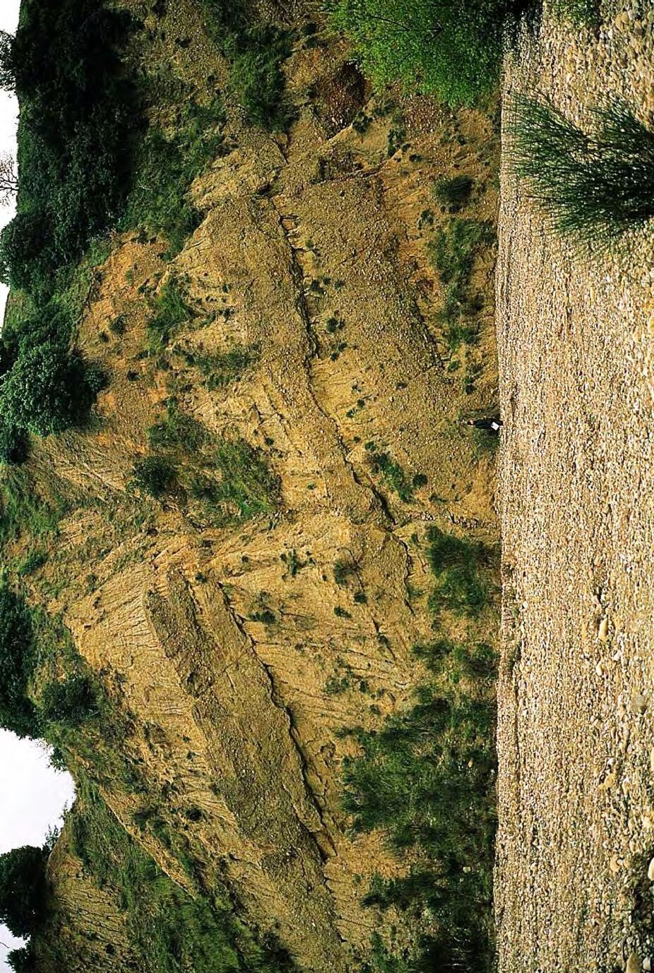
50Stacked alluvial lithofacies sequences. Coarse-grained lithofacies consist of pebbly sandstones and conglomerates deposited by sediment gravity flows; fine-grained lithofacies are mainly made up of flood-plain and lacustrine mudstones with interbedded fine-grained sandstones. Pliocene Catarozzo Group, Basilicata, southern Italy.
CHAPTER I: General concepts
SYSTEMS: AN OUTCROP-BASED ANALYSIS 78
TURBIDITE
Fig.
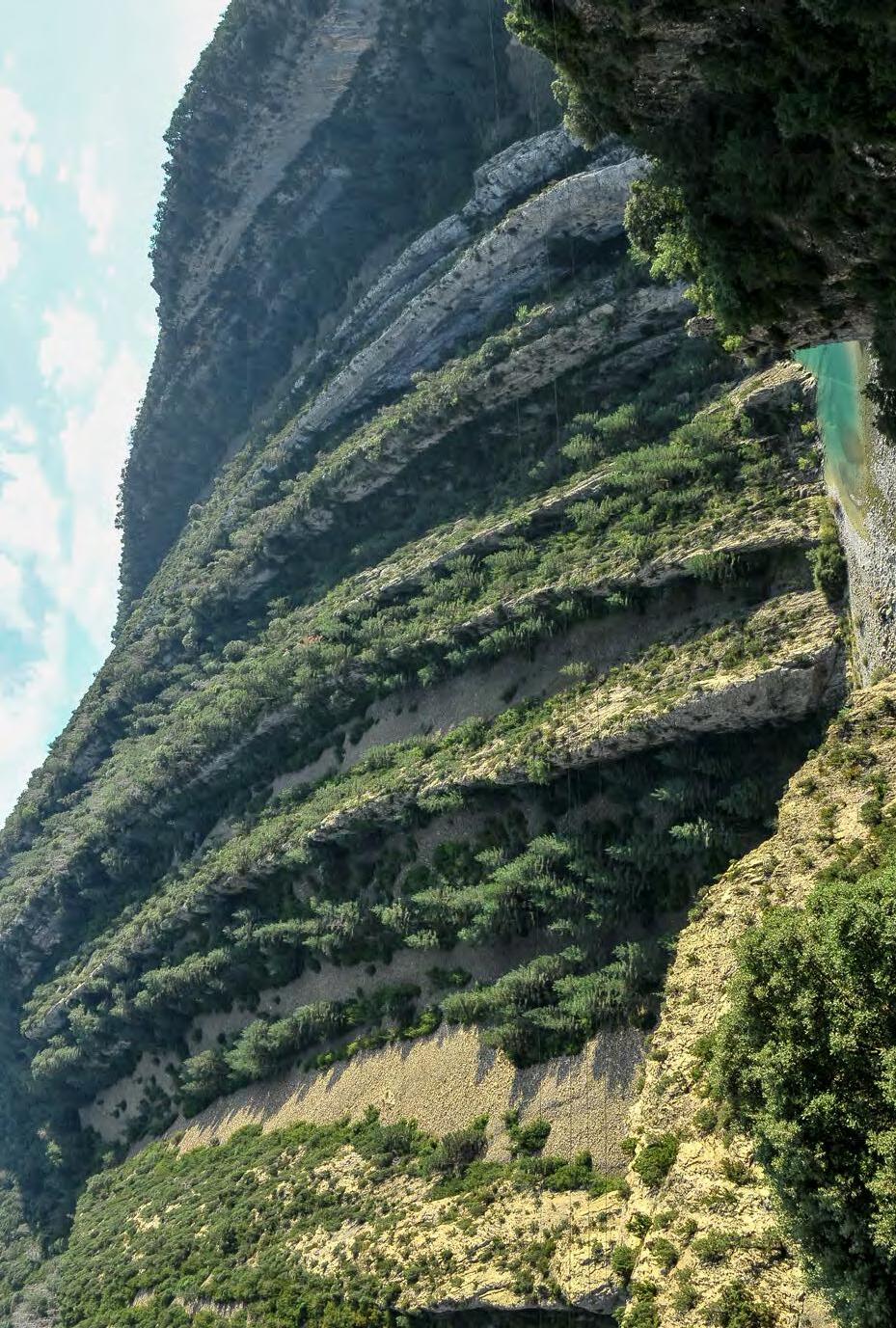
CHAPTER I: General concepts TURBIDITE SYSTEMS: AN OUTCROP-BASED ANALYSIS 79
Fig. 51Cyclic stacking of lithofacies sequences in a shallow-marine mixed (terrigenous and calcareous) depositional system. Younging direction is to the right. Western limb of the Boltana anticline.
Eocene Castigaleu Group, south-central Pyrenees.
The angular stratal relationship between the gently seaward dipping cross strata below and the flat-lying thinner beds above is referred to as “toplap”
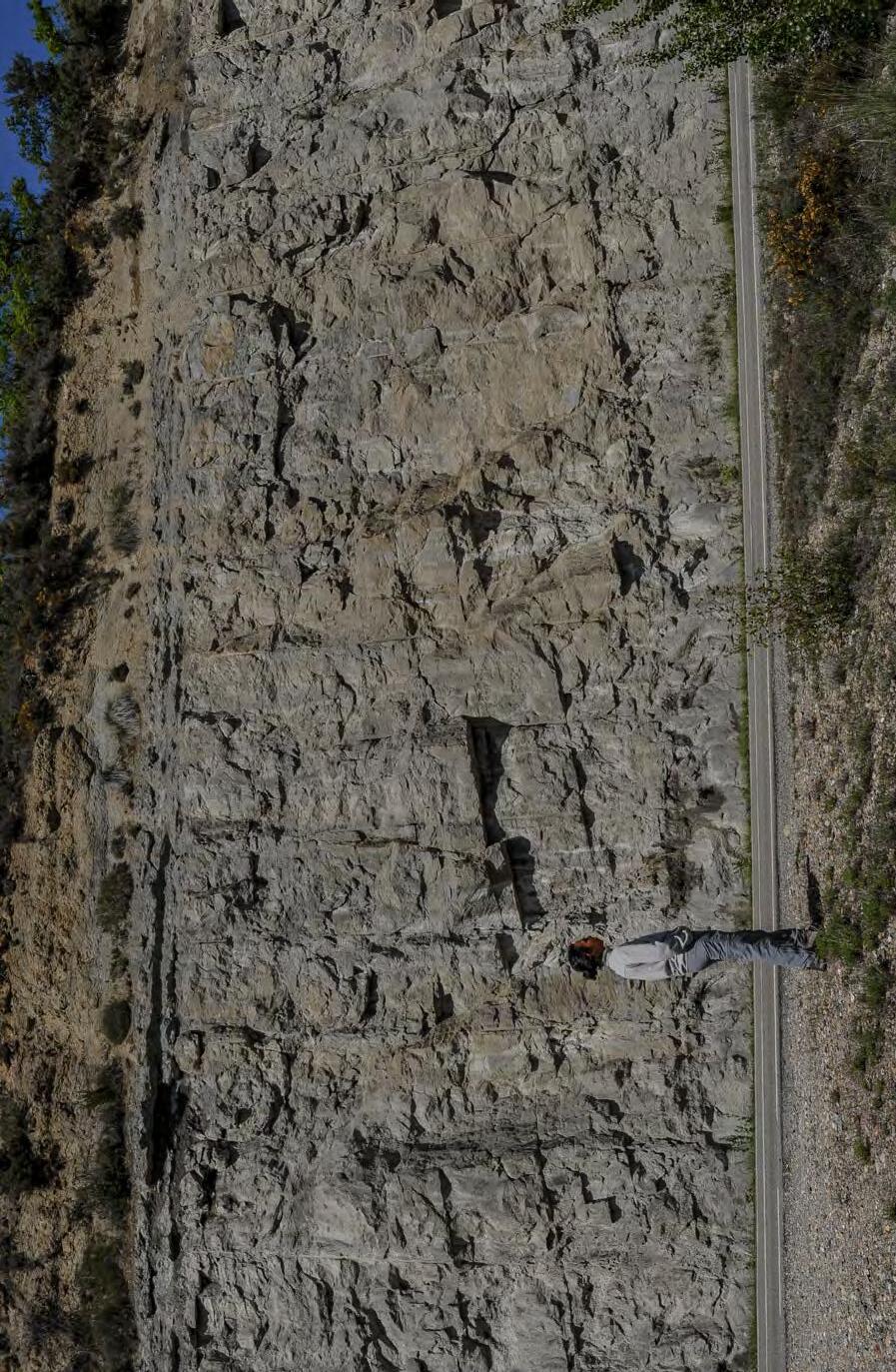
Seaward accreting sandstone beds ( prograding mouth bar) recording a depositional regression
This surface can be referred to as :
a. marine fl ooding surface,
b. ma ximum regression surface, or
c. abandonment surface
52Lithofacies sequence and its sequence-stratigraphic significance, Eocene Figols Group, Val Isabena, south-central Pyrenees. A sandstone lithofacies produced by a depositional regression at a channel mouth and characterized by seaward-dipping strata is overlain by a thin, transitional unit of flat-lying sandstone beds passing upward into mudstone-dominated facies. This boundary essentially records a period of time during which progradation (seaward-dipping strata) is replaced by aggradation following a local abrupt decrease in sediment supply or a sudden relative increase of sea-level and ensuing transgression.
Based on regional data, the second interpretation is here preferred.
CHAPTER I: General concepts TURBIDITE SYSTEMS: AN OUTCROP-BASED ANALYSIS 80
Fig.
Parasequences, as originally introduced and defined by Van Wagoner et al. (1988, 1990) and Mitchum and Van Wagoner (1991), are the “building blocks” of sequence stratigraphic units. A parasequence is a relatively conformable succession of genetically related beds or bedsets bounded by marine flooding surfaces and their correlative surfaces and is generally characterized by a coarsening- and shoaling-upward facies succession. The origin of parasequences is the same as that of the high-frequency depositional sequences, i.e., a 4th or 5th order cyclicity primarily controlled by orbital forcing. High-frequency sequences would preferentially form during the falling periods of the low-frequency curve, whereas parasequences would preferentially form during the rising ones. Though originally not defined by an order of thickness, it appears obvious that the physical scale of parasequences as intended by Van Wagoner et al. (1990) is a m- to dam-scale, as clearly shown by both outcrop and subsurface examples. As noted in subsequent work by several authors (e.g., Mutti, 1990; Posamentier and James, 1993; Mutti et al., 1994, 2000; Catuneanu, 2006; Darlymple, 2010), the problem is probably more complex than it would appear from the above definitions. In particular, the problem is to explain how packets of strata bounded by marine flooding surfaces (the Galloway’s criterion to define genetic sequences, see above) can be the “building block” of depositional sequences bounded by unconformities and their correlative conformities in the classic Exxon’s model. A second and similarly important problem arises from the fact that most workers have overlooked the importance of the equilibrium point, a concept introduced by Posamentier and Vail (1988) but apparently not fully explored in its practical application in later work. Based on the many examples reported in the literature, it can be safely said that parasequence scale can be equated with that of lithofacies as defined above (e.g., Mutti et al., 1994; Spence and Tucker, 2007; Tucker and Garland, 2010).
All these units are of fundamental importance in framing the results of facies analyses within sequence stratigraphic concepts and the problem is primarily based on our understanding of processes and environments and the way they change over relatively short time. Without a careful description and interpretation of the facies under examination and their component beds most of our conclusions would remain only theoretical. For this reason, the problem is amply discussed with pertinent examples in the following sections.
As shown in Figure 23, lithofacies analysis leads to define higher-order units that can be split into two groups. One group considers units mainly in terms of their paleoenvironmental significance and therefore defines short and long-lived depositional systems The other group recognizes elementary depositional sequences and the way they stack into small-scale composite depositional sequences. Both groups of units, requiring the integration of facies analysis and sequence stratigraphy are more amply discussed in the following sections mainly concerned with the sequence stratigraphic aspect of the problems.
IV.4 - LARGE-SCALE UNITS (MSUs)
These units form thick and relatively long-lived sedimentary bodies that define the main architecture of basin fills. Their recognition can only be based on a regional approach, taking into account facies analysis, sequence stratigraphy and the local and regional structural setting. At this physical and temporal scale, large-scale composite depositional sequences (in most cases the classic 3rd order sequences of Vail et al., 1977), resulting from the stacking of lower order units (see above), are the basic stratigraphic component of basin-fills. These units and their component systems tracts stack to form basinwide higher order units, or allogroups, whose origin is mainly controlled by tectonics.
IV.5 - A PRAGMATIC AND INFORMAL SEQUENCE STRATIGRAPHIC APPROACH
IV.5.1 - General
Most of the available sequence stratigraphic models actually deal with concepts and examples primarily derived from seismic data obtained from continental margins or from scattered field studies of exposed basin fills with limited tectonic activity. Since the sequence stratigraphic approach is certainly of general validity, its application to tectonically active basins is highly desirable and would be of great help for a better understanding of the huge sediment accumulations that can be observed in exposed orogenic belts, i.e. in geodynamic settings where tectonism plays a major role (Mutti, 1990; Catuneanu, 2006). Most importantly, this kind of approach would also considerably improve our understanding of the relationships between tectonics and sedimentation - a long-lasting problem already perceived and nicely reviewed several decades ago by Krumbein and Sloss (1958) in the early days of modern stratigraphy.
CHAPTER I: General concepts TURBIDITE SYSTEMS: AN OUTCROP-BASED ANALYSIS 81
The upper Cretaceous and Eocene marginal marine strata of the south-central Pyrenees provide in this respect a very good example of a basin fill which formed in the collisional setting of a foreland domain and thus affected by thrusting, folding and faulting during its infilling (see Munoz, 2002, for a general review of the tectonic setting). In the concluding chapter of the book, these relationships between tectonics and sedimentation will be amply discussed. Figure 53 shows the classic Monte Perdido thrust and a spectacular angular unconformity associated with a major phase of structural deformation.
Seismic data virtually do not exist, but the exposures are generally excellent and structural deformation is not so severe as in other circum-Mediterranean orogens (e.g., the Apennines). As a result, field work is greatly facilitated and with time the south-central Pyrenees have thus become a classic, world-renowned area for field-based studies and training programs. On the other hand, the lack of seismic data severely prevents the recognition of large-scale stratal configurations and thus a critical tool for delineating stratal stacking patterns typical of forced and normal regressions and transgressions as well as shoreline trajectories. Conversely, most of the work in exposed tectonically mobile basin fills is essentially based on the study of vertical sections and their correlation, and on the inferences that can be made from these limited data sets.
Mutti (1989) and Mutti et al. (1988, 1994) introduced a pragmatic approach to the sequence stratigraphic interpretation of these sediments with specific reference to the Eocene succession and to marginal, mostly flood-dominated deltaic deposits. Since in the field time is difficult to measure and high-resolution biostratigraphy is not routinely available, these authors suggested instead a physical and hierarchical approach serving the purposes of both regional mapping and detailed stratigraphic work. From the smallest to the largest, they recognized the following units (Figure 54):
• Elementary depositional sequence (EDS)
• Small-scale composite depositional sequence (SSCDS)
• Large-scale composite depositional sequence (LSCDS)
• Allogroups (abbreviated into groups)
Elementary depositional sequences stack to form small-scale composite depositional sequences. The
latter stack to form large-scale depositional sequences and these stack to form allogroups. All these units are bounded by unconformities and their correlative conformities. The hierarchical order is simply based on the relative thickness of each unit and on the lateral extent of the bounding surfaces. Basinwide unconformities and correlative conformities define allogroups and are related to major and regional phases of structural deformation, thus being characterized by marked angular unconformities along basin margins. Their identification and tracing permit to correlate alluvial and marginal marine strata with basinal turbidite systems (Figure 1). Setting aside turbidites for the moment, lower-rank units in alluvial and marginal marine strata are bounded by surfaces which progressively decrease their lateral extent being recorded by depositional units of similarly limited extent.
IV.5.2 - Elementary depositional sequences (EDSs), equilibrium point and the problem of parasequences
The basic unit of this practical classification has been termed “elementary depositional sequence” (EDS) by Mutti et al. (1994), “elementary” referring to the fact that such unit is the smallest depositional sequence observable in the field, much in the same way as a lamina is the smallest stratal unit in the hierarchical classification of layers of Campbell (1967). Each EDS basically coincides with a lithofacies sequence made up of a basal relatively coarse-grained lithofacies (mostly a sandy lithofacies) overlain by a mudstone-dominated lithofacies. Units of this type generally develop over thickness between a few meters up to a few tens of meters and are pervasive in alluvial, marginal marine and deep-water settings.
With particular reference to delta-front successions and therefore to relatively shallow water environments, the most sensitive to relative sea level variations, each EDS basically records a forestepping sandy episode followed by an episode of backstepping or abandonment with ensuing deposition of fine-grained facies. Each EDS is thus characterized by an overall fining- and deepening-upward trend. This trend may be interrupted by an increase in sand deposition toward the top of the mudstone lithofacies. This increase apparently mimics the falling stage of sequence- stratigraphic models (see above).
CHAPTER I: General concepts TURBIDITE SYSTEMS: AN OUTCROP-BASED ANALYSIS 82
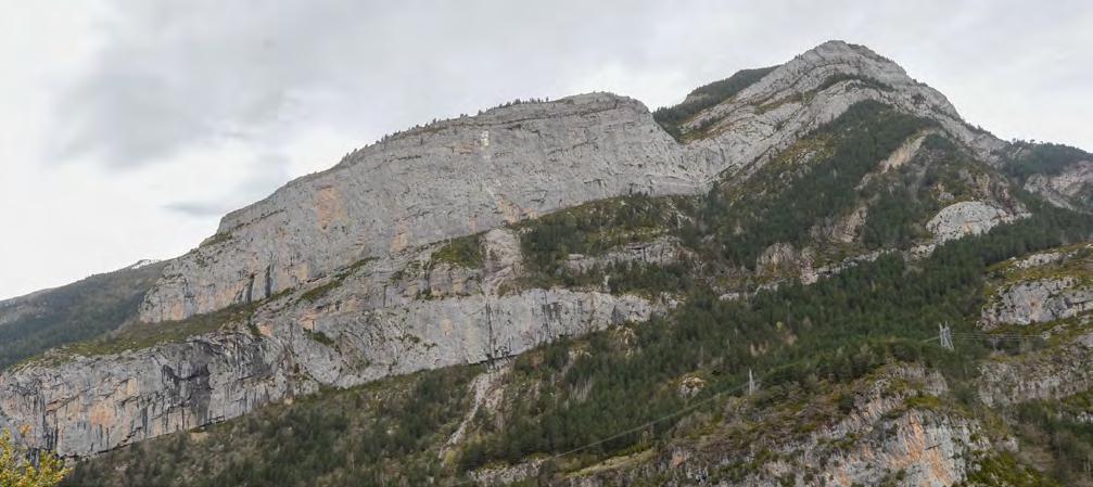
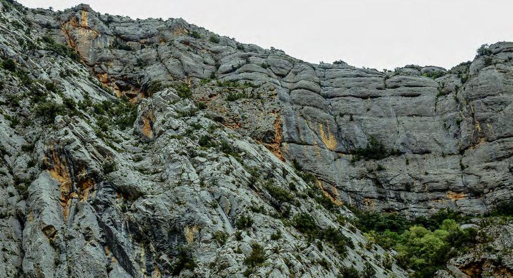
CHAPTER I: General concepts TURBIDITE SYSTEMS: AN OUTCROP-BASED ANALYSIS 83
Fig. 53 - Tectonically-induced angular stratigraphic unconformity (Pallaresa valley, Pyrenees).
Cretaceous carbonates
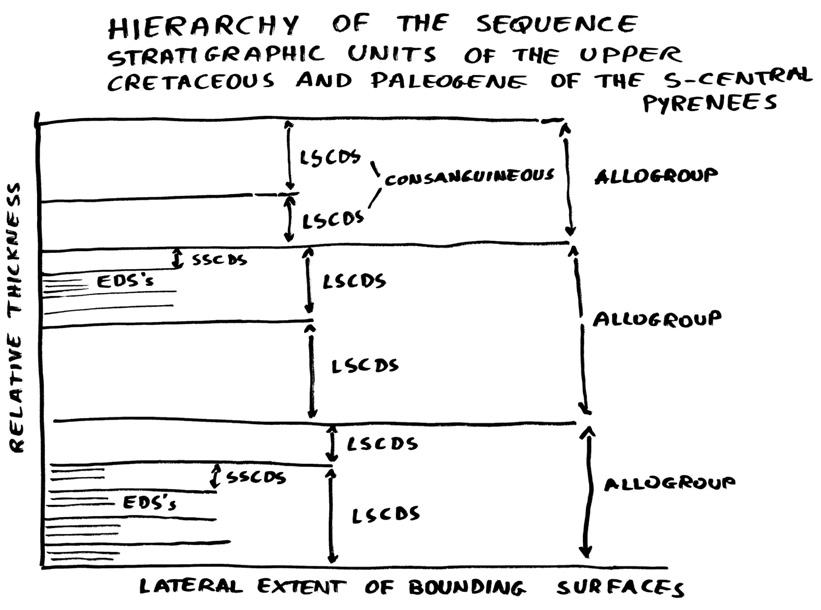
The internal facies and facies associations observed within these sequences may vary greatly depending upon many controlling factors such as the location of the sequence considered along the original depositional profile, the ratio between the rates of subsidence and relative sea level variation (equilibrium point, see later), the sediment flux, and the sedimentary processes of the depositional system or systems active at that specific location at any considered time.
The bounding surfaces of EDS are unconformities and correlative conformities that develop with characteristics controlled by the position of the EDS considered along the depositional profile and, more specifically, by the position of the equilibrium point. The equilibrium point has been introduced by Posamentier and Vail (1988) and defines two zones along the depositional profile: (1) a zone of relative sea level rise that is sea-
ward of the equilibrium point, and (2) a zone of relative sea level fall that is landward of the equilibrium point. These two zones are identified by the ratio between the rate of sea level fall and the rate of subsidence.
Mutti et al. (1994, 2000) have argued that, if the equilibrium point is located in a shallow-marine environment or somewhere in the shelf, the zones are actually three:
(1) a seaward zone of the equilibrium point where the water depth increase, (2) a landward zone of and adjacent to the equilibrium point where the water depth decreases and the depositional profile is shallowing, and
(3) a landward zone and away from the equilibrium point where the rate of relative sea level fall largely exceeds the rate of subsidence leading to subaerial exposure (Figure 55). In this simple scheme the way in which unconformities and correlative conformities can develop in alluvial, nearshore and shelfal settings is incapsulated.
CHAPTER I: General concepts TURBIDITE SYSTEMS: AN OUTCROP-BASED ANALYSIS 84
Fig. 54 - Hierarchy of the sequence stratigraphic units of the upper Cretaceous and Paleogene of the south-central Pyrenees (from Mutti, 1989 and Mutti et al., 1994).
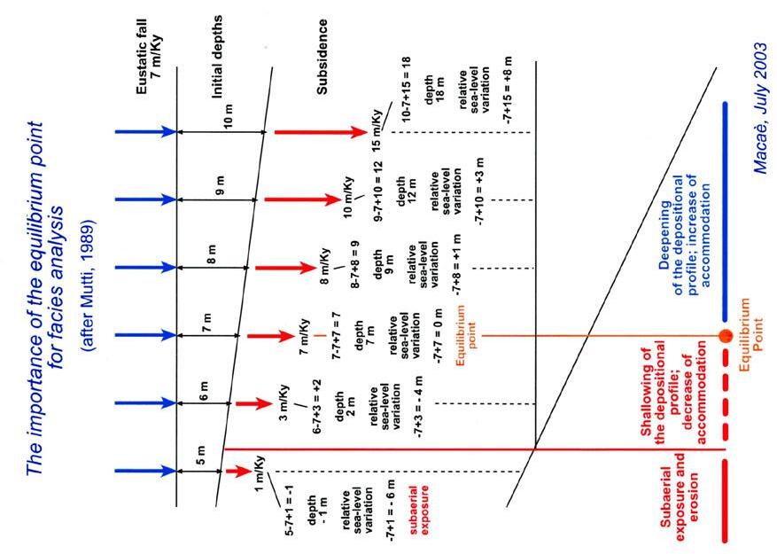

Fig. 55The concept of “equilibrium point” introduced by Posamentier et al. (1998) above. On the right and as a joke for my students (see rates), a diagram shows the importance of the equilibrium point in determining variations of water depth along the depositional profile and thus controlling processes, notably waves and tides, and facies in relatively shallow-water environments.
CHAPTER I: General concepts
SYSTEMS: AN OUTCROP-BASED ANALYSIS 85
TURBIDITE
A B
Recognizing unconformities associated with angular discordance, subaerial exposure, or sharp contacts between incompatible facies is generally easy. The problem becomes considerably more difficult in the case where the depositional profile undergoes shallowing. In this case, facies and facies associations are the only available tool for detecting the process.
Figures 56 and 57 show a real example of sequence boundaries recognized in an Eocene tide-dominated delta in the south-central Pyrenees and herein interpreted as produced by shallowing of the depositional profile recorded by a facies change. Note the internal complex architecture of the sandy lithofacies that consists of prograding tidal bars with a marked coarsening and shallowing-upward trend interrupted by a sharp transgressive surface (marine flooding surface) resting upon a thin unit of highly bioturbated sandstones. The basal unconformity may be relatively sharp or expressed by a very thin reworked unit of the underlying finer-grained and bioturbated lithofacies containing mudstone clasts. Probably the local water depth-driven shallowing of the depositional profile is recorded only when tidal action becomes strong enough to leave its signature in the resulting facies. Higher in the sandy lithofacies, large-scale tidal bedforms (tidal bars) record a sediment-driven shallowing of the depositional profile, i.e., a sort of depositional regression.
Figure 58 shows another example of EDS, very common in fluvial-dominated delta-front strata, where the sandy lithofacies consists of a basal sandstone facies made up of graded beds with HCS conformably overlain by mudstones with thin sandstone beds passing upward into a prograding mouth-bar sandy deposit. The latter can be directly and sharply overlain by the mudstone lithofacies and, in mixed systems, by associated fossiliferous shelfal carbonates as in the example shown. Both the sharp surface and the carbonates imply the demise of the fluvio-deltaic system below and
the deepening of the depositional profile. The lower boundary of the sequence is a sharp contact with an underlying mudstone lithofacies. Its interpretation in terms of water depth is here difficult because the graded sandstone beds indicate a deposit of sediment gravity flows that undergo the well-known “bottom-seeking” effect, i.e., these flows tend to reach and deposit in the deepest topographic low locally available or where external and internal friction prevail, forcing the flow to deposit its load. This zone has no limiting water depth. Conversely, the sudden facies change observed along the lower boundary of the EDS clearly indicates a similarly sudden change in the sediment flux through powerful flood-generated hyperpycnal flows. The best explanation of this change seems an abrupt climate change that may or may not be associated with sea level. Therefore, EDSs of this type, as suggested by Mutti (2012), are probably mainly controlled by flood magnitude and frequency related to climate cycles (Figure 59). Both types of EDS described above record a cyclicity in the Milankowich range (Wahery, 1999; Torricelli et al., 2006). Fluvio-deltaic EDSs are amply discussed in the next chapter.
The scheme of Figure 60 shows the relationships between EDSs and parasequences. EDSs record a high-frequency orbital cyclicity and are bounded by surfaces that record changes in water depth and/or in climate-controlled sediment flux to the sea. Parasequences are herein explained as shoaling-upward facies successions that record progradational events taking place in the upper portions of some sandy lithofacies where environments, processes and sediment supply are favourable. Essentially, parasequences record shoaling-upward monogenic or hybrid facies associations typical of many depositional settings (see above). Depositional sediment-driven regressions and downcurrent accretion of many sandstone bars are probably the most common occurrence of these features.
CHAPTER I: General concepts TURBIDITE SYSTEMS: AN OUTCROP-BASED ANALYSIS 86
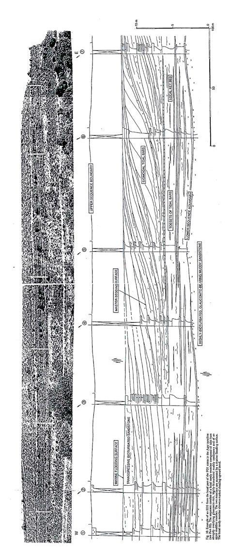
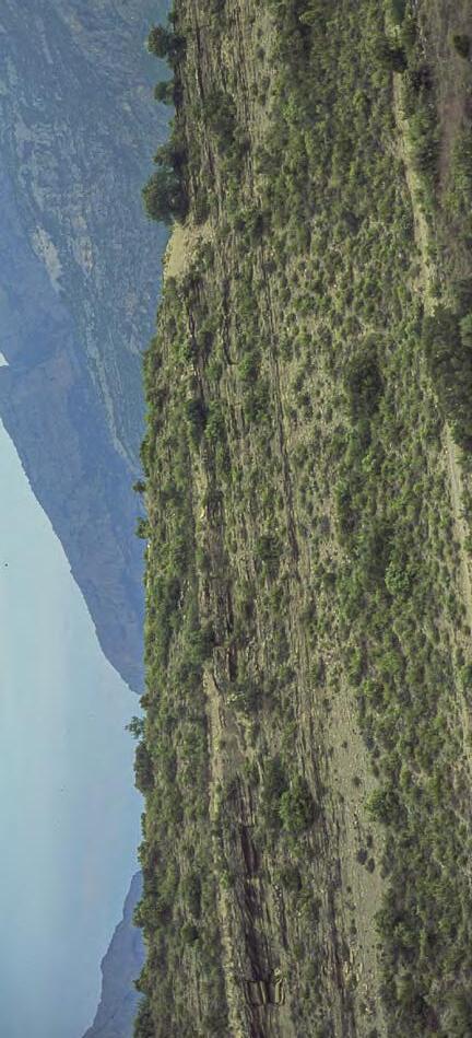
Marine flooding surface
Close up of the basal unconformity
Basal unconformity
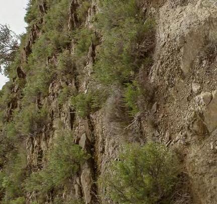
Detailed cross-section of an elementary depositional sequence over a distance of some 0.5 km, from the Eocene Figols Group, Ager basin, south-central Pyrenees. The section is dip-oriented (land is to the right) and shows a lower tide-dominated sandstone lithofacies sharply overlain, through a marine flooding-surface, by a mudstone-dominated lithofacies. See text for explanation.
CHAPTER I: General concepts
SYSTEMS: AN OUTCROP-BASED ANALYSIS 87
TURBIDITE
Fig. 56
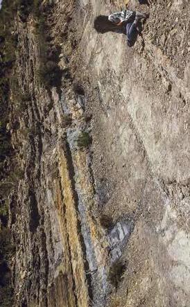

Shoaling-upward profile of tidal bars
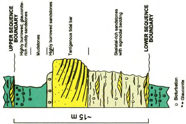

Sequence boundaries
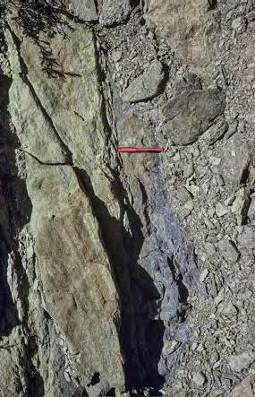
Fig. 57Interpretation of the EDS of Figure 56. Note the increased sand content in the mudstones (upper right) heralding the onset of the upper sequence boundary and being onceptually similar to the falling stage of classic sequence stratigraphic models.
CHAPTER I: General concepts
SYSTEMS: AN OUTCROP-BASED ANALYSIS 88
TURBIDITE
TURBIDITE
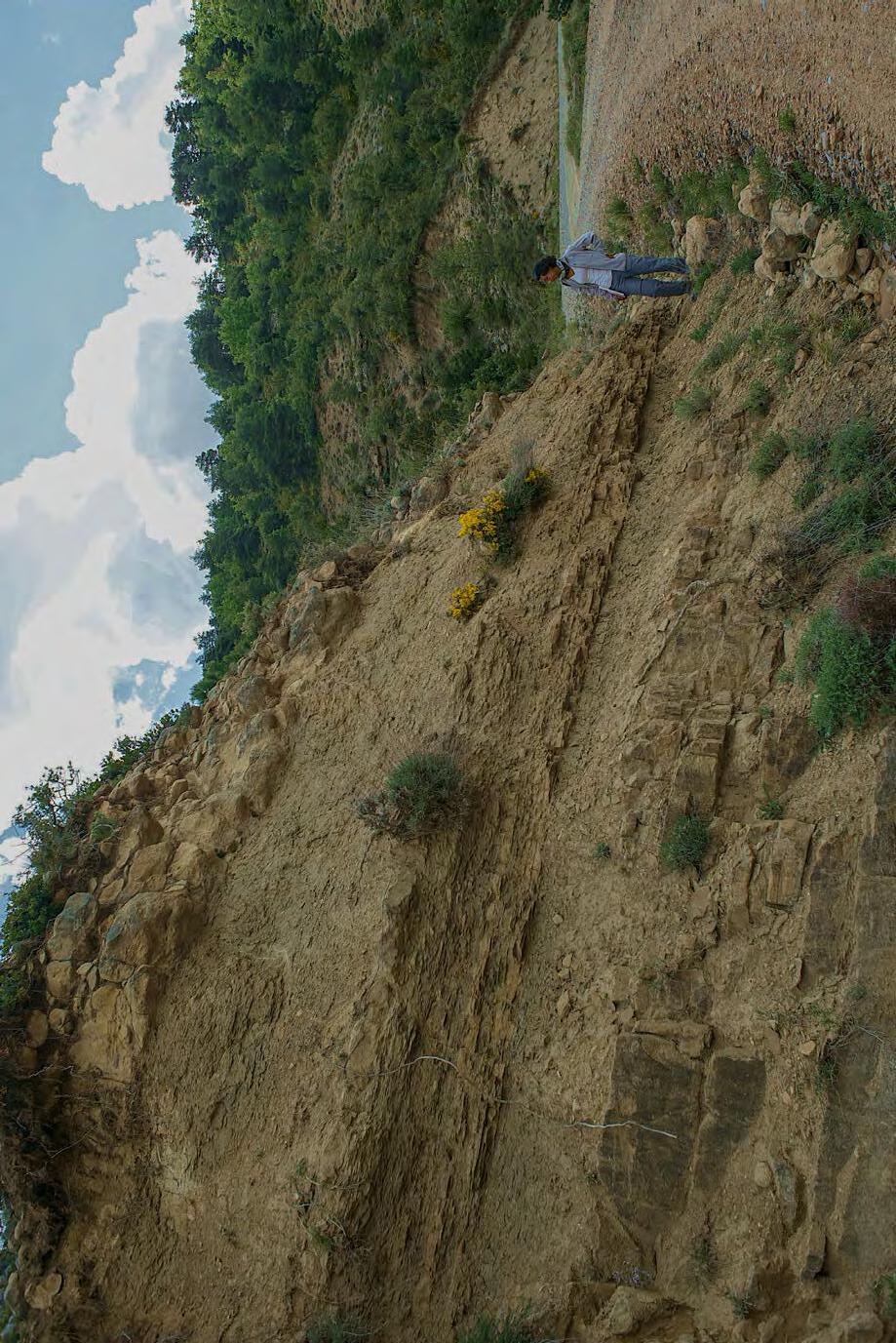
Foramol-type carbonates
Maximum regression surface
Sandstone lobe
south-central Pyrenees). Shelfal carbonates are associated with transgressive and high-stand mudsto-
(Eocene Figols
a mixed
EDS
-
(see text for more details).
CHAPTER I: General concepts
SYSTEMS: AN OUTCROP-BASED ANALYSIS 89
Fig. 58
Example of an
in
system
Group, Isabena valley,
nes
Highstand bioturbated muddy sandstone
Mouth-bar thin-bedded sandstone
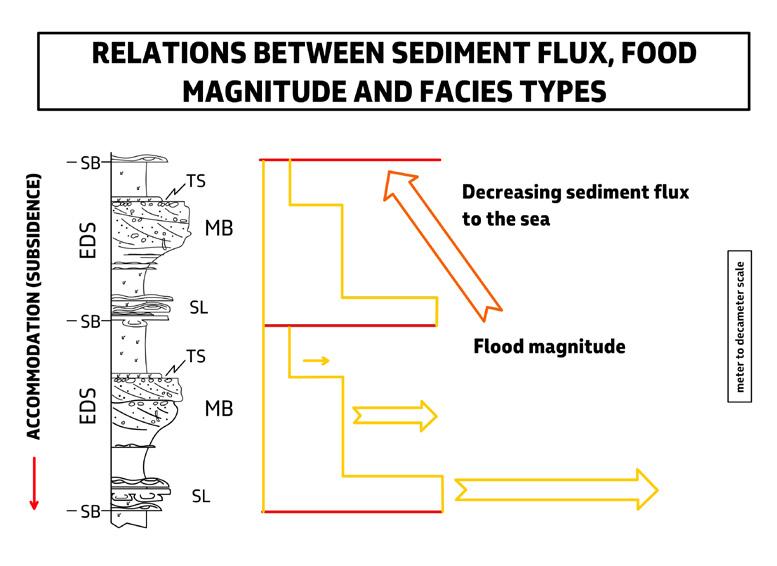
As shown by Figure 60, the lower boundary of parasequences is transitional to muddier and slightly deeper facies; the upper one is a marine flooding surface recording either a rise of relative sea level, a sudden decrease in sediment supply or a combination thereof. If defined in this way, that this writer would consider as a reasonable one, parasequences simply record a facies association and not a depositional sequence. A conceptual scheme showing the basic relationships between EDSs and parasequences as a function of the equilibrium point is shown in Figure 60 A; it will be noted that in this scheme parasequences are maintained as theoretically possible thin units recording the stepwise rise of sea level above the basal sandy lithofacies of EDSs, which would mimic a transgressive system at its elementary scale. A possible example of these thin units has been described by Mutti et al. (1994) from the Eocene Figols Group in the Ager basin, south-central Pyrenees. It follows from the above discussion that the term “parasequence” as originally defined (see above) is not appropriate to identify the “building block” of sequence stratig-
raphy; the term carries with itself many ambiguities and should hopefully be abandoned to avoid further confusion. Obviously, the interpretation suggested above implies a new way in reconstructing the stacking pattern of lithofacies sequences in both outcrop and wireline analysis.
IV.5.2.1 - The importance of EDS
In addition to their conceptual importance (see above), EDSs can be considered as the basic operational unit of sequence stratigraphic analysis. These units can be mapped at an appropriate scale and be used to prepare detailed stratigraphic cross sections in both surface and subsurface studies. Obviously, this type of stratigraphic analysis is very time-consuming and can be carried out only for limited portions of a basin fill, requiring an integration of logged sections and lateral tracing of the lithofacies. The lateral tracing in the field is generally based on the well-known “walking out” technique with the help of aerial photographs and drone-assisted surveys.
CHAPTER I: General concepts TURBIDITE SYSTEMS: AN OUTCROP-BASED ANALYSIS 90
Fig. 59 - Relations between sediment flux, flood magnitude and facies types in flood-dominated delta-front elementary depositional sequences.
Meter to decameter scale
ELEMENTARY DEPOSITIONAL SEQUENCE (EDS)
Regressive-transgressive succession bounded above and below by sequence boundaries (SB)
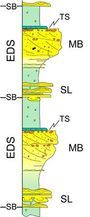
PARASEQUENCE
Shoaling-upward succession bounded above and below by marine flooding surfaces
SL : delta-front sandstone lobes
MB : mouth-bar (channel-exit) deposits
TS : transgressive deposits associated with marine flooding surfaces
Sequence boundary (unconformity and correlative conformity)
Marine flooding surface (base level rise)
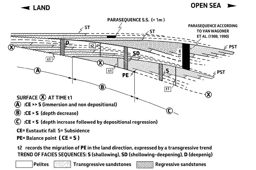
CHAPTER I: General concepts TURBIDITE SYSTEMS: AN OUTCROP-BASED ANALYSIS 91
Fig. 60 - Sequence stratigraphy of marginal-marine fluvio-deltaic systems: Parasequences and Elementary Depositional Sequences (EDS).
Fig. 60 A - Conceptual scheme showing the relationships between EDSs and parasequences as related to the equilibrium point. Note that parasequences are conceptually maintained as thin units recording incremental sea-level rise at its elementary scale (from Mutti, 1990).
Each EDS is actually the expression of a short-lived depositional system the duration of which is in the Milankowich range and is recorded by the stratigraphic thickness between the two bounding surfaces. Since depositional systems have a finite extent, an EDS should be recognizable only over this area. Assuming a fluvio-deltaic system, the sandstone body forming the basal lithofacies of an EDS will ideally change facies and geometry in a seaward direction according to the scheme of Figure 61. The resulting EDS expression will thus change depending on its position along the depositional profile, as far as this expression will be maintained by the lithologic contrast and the bounding surfaces will be recognizable.
Surprisingly, however, many EDSs maintain their expression over considerable distance, even over sev-
eral km. Carminatti (1992) was able to document detailed correlations of these EDSs over some 20 km and through a stratigraphic thickness of about 1000m in the Eocene Figols Group, south-central Pyrenees (Figure 62). Impressive lateral continuity of these sequences is also shown from aerial photographic mapping (e.g., Sgavetti 1992). It is here suggested that this lateral continuity strongly favours an allocyclic (relative sea level variations, climate cycles) control on most sequence boundaries and, in addition, a nearly simultaneous activation of sediment flux to the sea in different, though roughly adjacent, small depositional systems thus giving way to a sort of small-scale systems tracts within individual EDSs. Local structural control may affect deposition even at this scale (see later).
Expression of EDS at different locations along the depositional profile
CHAPTER I: General concepts TURBIDITE SYSTEMS: AN OUTCROP-BASED ANALYSIS 92
Fig. 61 - Proximal-distal variations of sandstone lithofacies geometry (from Mutti,1989).
Shalying out
C B A Thinning BASINWARD LANDWARD Incised valley fill
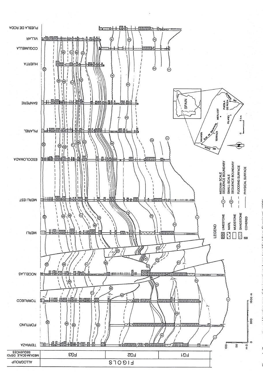
Fig. 62Detailed stratigraphic cross-section of the Eocene Figols Allogroup, between the Isabena and Esera valleys, in the south-central Pyrenees (slightly modified from Carminatti, 1992). The section shows a remarkable lateral continuity of small-scale sequences (EDSs) particularly in the upper portion of the section, which is less affected by synsedimentary structural deformation. Basinward direction is to the left.
CHAPTER I: General concepts TURBIDITE SYSTEMS: AN OUTCROP-BASED ANALYSIS 93
Needless to say, EDS are easily recognizable only where their boundaries are well expressed as in the cases discussed above, i.e., where the shallowing of the depositional profile or the sudden increase in sediment flux can be recognized through a detailed facies analysis. These conditions are met particularly in shallow-water deposits which are the most sensitive to the migration of the equilibrium point (see above). If EDSs are observed away from this zone, the problem becomes more complex and has to keep into account processes and their efficiency in carrying sediment away from river mouths (see following chapters).
IV.5.2.2 - EDSs, short-lived and long-lived depositional systems (and elements)
Short-lived depositional systems of EDSs stack to form long-lived depositional systems, i.e., systems which are cyclically activate and deactivated (Figure 62 A).
In current sequence stratigraphic models, depositional systems are arranged in a predictable stratigraphic order within each depositional sequence as lowstand, transgressive, highstand and falling-stage systems tracts (Figure 13) but are little described in terms of specific facies and facies associations. A more simple and geologically understandable terminology has been suggested in Figures 14 and 15, emphasizing the vertical stratigraphic succession of depositional systems as related to prograding, receding and erosive (degradational) events within a cycle of relative sea level variation.
Depositional systems were defined as three-dimensional assemblages of lìthofacies genetically linked by active (modern) or inferred (ancient) processes and environments (Fisher and McGowen, 1967; Brown and Fisher, 1977). These systems are designated by a genetic term, e.g., a delta system; components of a delta system are referred to simply as facies, e.g., a delta front facies. The terms “depositional system” and “facies” thus define large-scale features which have a seismic expression and contemporaneous depositional systems can be linked to produce a systems tract, such as for example a tract composed of fluvial, delta, shelf, and slope systems (Brown and Fisher, 1977, p.215).
The concepts above, which can be very useful in seismic stratigraphic studies and, more generally, in broadly regional stratigraphic analysis, are however inadequate for the purposes of high-resolution
sequence stratigraphy because of an obvious scale problem. The concepts actually describe genetic stratigraphic units developed at such a large scale that the term “facies” can be used to denote a seismically defined delta front. These concepts clearly need to be applied also to the physical and temporal scales of EDSs which contain the sedimentological information upon which a system can be identified, though at a small scale and over a short interval of time.
We will therefore consider herein (1) short-lived depositional systems expressed by EDSs, and 2) and longlived depositional systems formed by the stacking of consanguineous EDSs recording similar processes and environments. Clearly, without the basic sedimentological information gathered from the analysis of its component EDSs a long-lived depositional system would be hardly recognizable. Similarly, without this information it would be difficult to detect its vertical facies variations and understand its stacking pattern.
It is also suggested here that the term “facies”, as intended by Brown and Fisher (1977), be replaced by “depositional element”, and meant to define the main environments that can be recognized in the system under consideration. The example of Figure 63 A shows an elemental subdivision of a fluvial-dominated delta system into its three basic elements: (1) a delta plain, (2) a delta front, and (3) a prodelta. Each of these elements is characterized by its own facies, facies associations and types of EDS. It will be noted that the three elements are coeval, thus defining an elements tract. As discussed in the next chapter, flood-dominated fluvio-deltaic systems have very distinctive expressions of EDSs depending upon their position along the depositional profile and the position of the equilibrium point at the time considered (Figure 63 B).
Similar elements tracts can be established for other types of system. This elemental approach may greatly help to recognize the main transgressive and regressive episodes within the system under consideration where reliable stratigraphic correlations are available. Elements are here intended in the sense of Mutti and Normark (1987, 1991), i.e., operational and mappable depositional units defined by specific facies associations, sand body geometry and EDS characteristics (Figures 64 - 67).
Concepts and problems of an integrated approach to sedimentological and sequence stratigraphic interpretations of exposed successions are further discussed in the final chapter.
CHAPTER I: General concepts TURBIDITE SYSTEMS: AN OUTCROP-BASED ANALYSIS 94
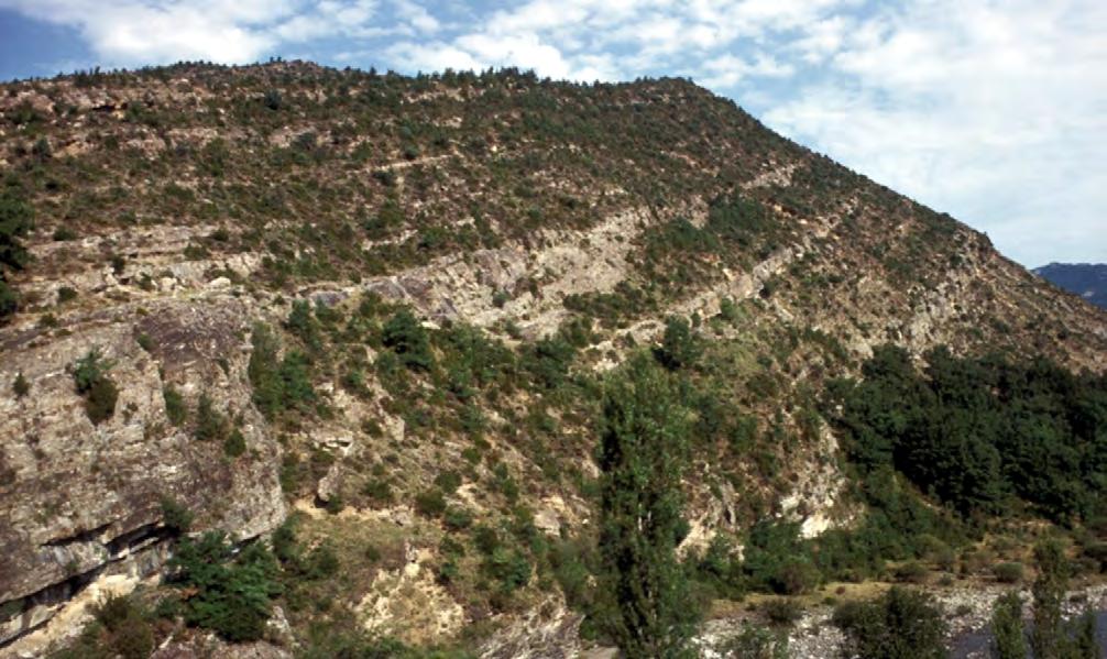
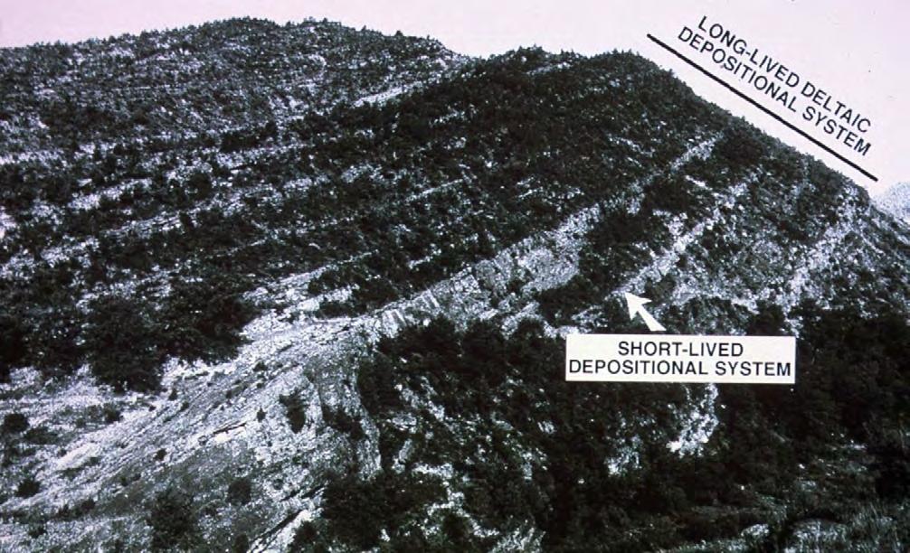
CHAPTER I: General concepts TURBIDITE SYSTEMS: AN OUTCROP-BASED ANALYSIS 95
Fig. 62 A - Example of short-lived and long-lived depositional system Note the cyclic stacking pattern of lithofacies and related EDSs for a closeup. Facies and facies associations indicate a general delta-front environment. The vertical evolution of the EDS characteristics indicates a large-scale composite depositional sequence. The exposure is a beautiful example of how facies analysis and sequence stratigraphy can be integrated Eocene Castigaleu Group, Esera valley, Pyrenees.
FACIES AND FACIES ASSOCIATION
fluvial sands
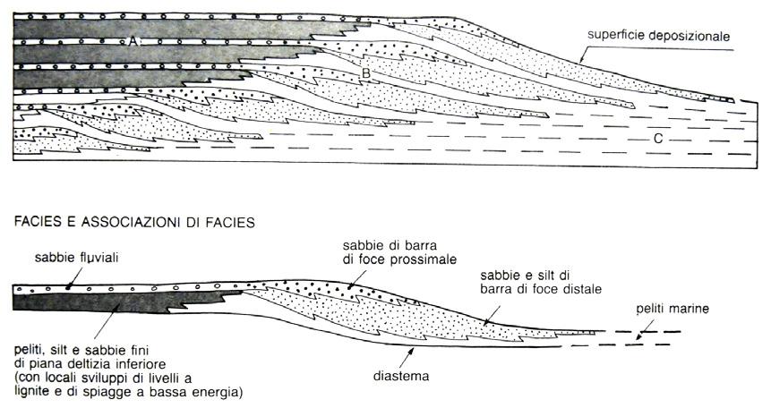
pelites, silt and fine sands of the lower deltaic plain (with local lignite developments and low-energy beaches
proximal mouth bar sands
distal mouth bar sands and silt
depositional surface
marine pelites
diastema
B
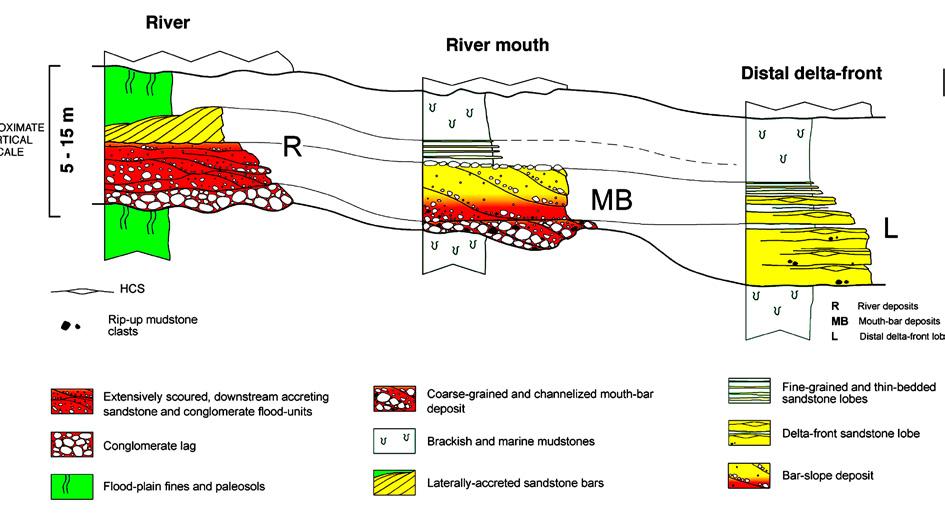
CHAPTER I: General concepts TURBIDITE SYSTEMS: AN OUTCROP-BASED ANALYSIS 96
A
Fig. 63 - A. Example of the subdivision of a prograding fluvio-deltaic depositional systems into three basic depositional elements made up of facies associations indicating deposition in delta plain, delta-front and prodelta environments. The scheme is also an example of elements tract (from Bosellini et al., 1989). B. In the case of flood-dominated fluvio-deltaic systems, each element will show EDSs with different characteristics as related to different processes and to the position of the equilibrium point at any considered time (modified from Mutti et al., 1996, 2000).
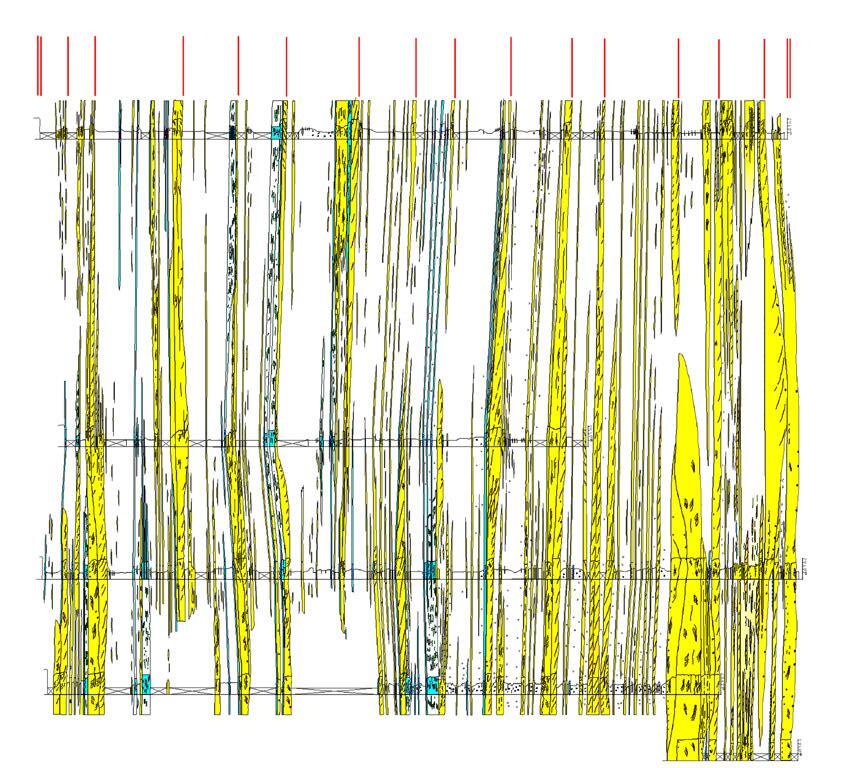
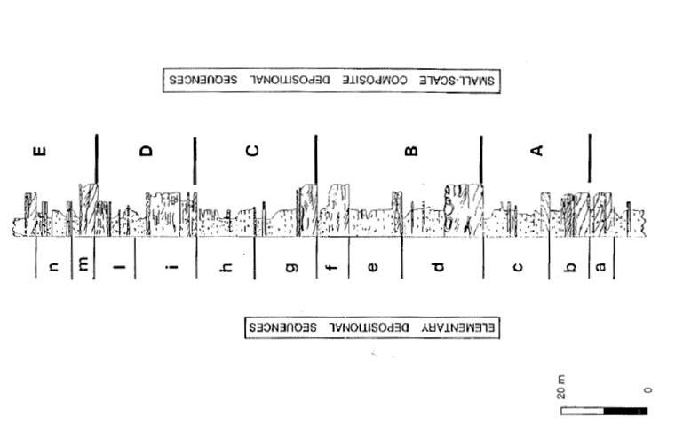
CHAPTER I: General concepts TURBIDITE SYSTEMS: AN OUTCROP-BASED ANALYSIS 97
Fig. 64
Relationships between EDS´sand small-scale composite depositional sequences in the delta-front strata of the Castigaleu Group, Esera valley.
Large-scale composite depositional sequence
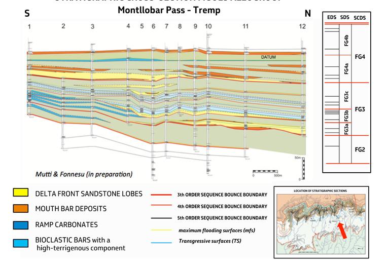
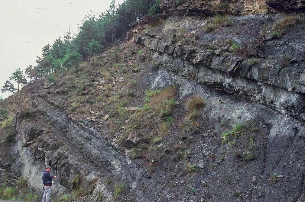
CHAPTER I: General concepts TURBIDITE SYSTEMS: AN OUTCROP-BASED ANALYSIS 98
Fig. 65 - Stratigraphic cross-section figols allogroup.
Fig. 66 - EDSs recording short-lived depositional systems. Yellow arrows indicate sequence boundaries. LSMB: lowstand mouth bar, RS: receding bioturbated sandstones (transgressive system), MFS: apparent maximum flooding surface, HS mdst: highstand mudstones, FSMB: ? Small, falling-stage mouth bar, LSSDTL: lowstand sandstone lobe.
MFS
MFS
LSMB
HS mdst RS (TST)
FS MB
LSSDTSL
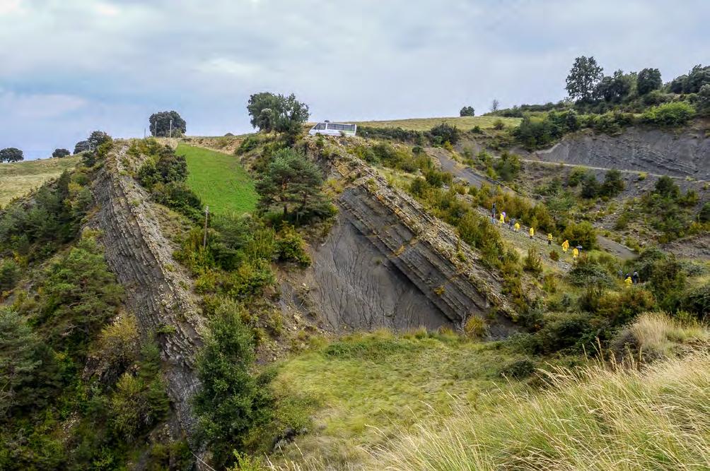
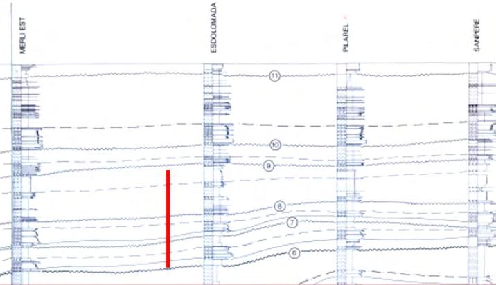
CHAPTER I: General concepts TURBIDITE SYSTEMS: AN OUTCROP-BASED ANALYSIS 99
Fig. 67 - Esdolomada - stacking pattern of EDSs indicating an overrall transgressive (retrogradational) system tract cuminating into a highly-fossiliferous condensed section.
Condensed section
CHAPTER II: TURBIDITES
I - TURBIDITES: BRIEF HISTORICAL REVIEW OF SELECTED PREVIOUS WORK
I.1 - GENERAL
Turbidites are among the most popular, interesting and beautiful deposits of the sedimentary record and occur worldwide in a variety of tectonic and depositional settings spanning in time from Precambrian to Recent. They are known particularly from orogenic belt basins where they give way to impressively thick successions of alternating sandstones and mudstones. Some spectacular exposures of these sediments are the epitome of layering (Figure 68).
Their economic importance is related to the hydrocarbon exploration and production in many offshore regions (e.g., the North Sea, the Gulf of Mexico, and the Brazilian offshore basins) where turbidite sands form prolific reservoirs in many oil fields. Successful exploration of these sediments depends on predicting where sand accumulations preferentially occur within a given deep-water depositional system and, on our ability, to predict reservoir quality of sandstone bodies. Therefore, both exploration and exploitation require a sound knowledge of the basic principles of turbidite depositional systems and their component facies and facies associations.
Probably the term “turbidites” implies so many different things, concepts and models that most people unfamiliar with the literature are inevitably confused. I think that the meaning of the term should be seriously discussed among sedimentologists to find a general consensus on its use. During the past two or three decades apparently, most workers have tried to elaborate their data and ideas mainly based on their own datasets with little critical evaluation of previous literature and thus of different datasets and approaches. As a consequence, communication among workers has become increasingly difficult.
Particularly in recent years, there has been a sort of revolution in the attempt to understand turbidite sedimentation. Most relevant research has moved to laboratory experiments, monitoring of modern turbidity
currents in the deep sea, numerical modeling, or to detailed outcrop studies aimed at clarifying the meaning of some types of facies (e.g, shale-clast bearing beds) and depositional setting (e.g., cross-current facies tracts against bounding slopes) and their relevance in assessing reservoir quality. Terms like “turbidite” and “turbidity current” are progressively losing their meaning and many papers do not even refer to the main geological problem, that is how we can interpret facies, facies associations and their component beds, keeping in mind their variety and in an attempt to develop some simple schemes of general validity for outcrop and subsurface studies.
Though tempered by a long experience with seismic data and core analysis from many basins worldwide, it is my strong conviction that the information we can obtain from exposed turbidite successions of orogenic belts is still under-appreciated. Therefore, this chapter heavily relies upon outcrop studies and especially on turbidite systems of foreland basins with which I’m most familiar. Needless to say that the concept of “turbidites” was born from these sediments.
The complexity of the problems involved requires a brief historical review of the way in which our knowledge of turbidites has evolved with time. The review is limited on purpose to a number of selected papers which I think are most pertinent to this chapter. The interested reader can find more extensive reviews in several publications (e.g., Walker, 1973; Mutti et al., 2009; Shanmugam, 2016; Pickering and Hiscott, 2016). Then this chapter expands on turbidite systems and their component elements emphasizing sandbody geometry and general processes. The last part of the chapter offers a new and simple scheme of classification of turbidite facies that describes the basic facies groups encountered in these sediments, ranging from conglomerates to mudstones, and discusses the way these groups and their component facies can be used to reconstruct genetic schemes (facies tracts) for predictive purposes. This part of the chapter includes an extensive photographic inventory of the many types of bed that form the broad spectrum of turbidite facies. Many of these problems are discussed in more detail in Mutti et al. (in preparation).
CHAPTER II: Turbidites TURBIDITE SYSTEMS: AN OUTCROP-BASED ANALYSIS 100
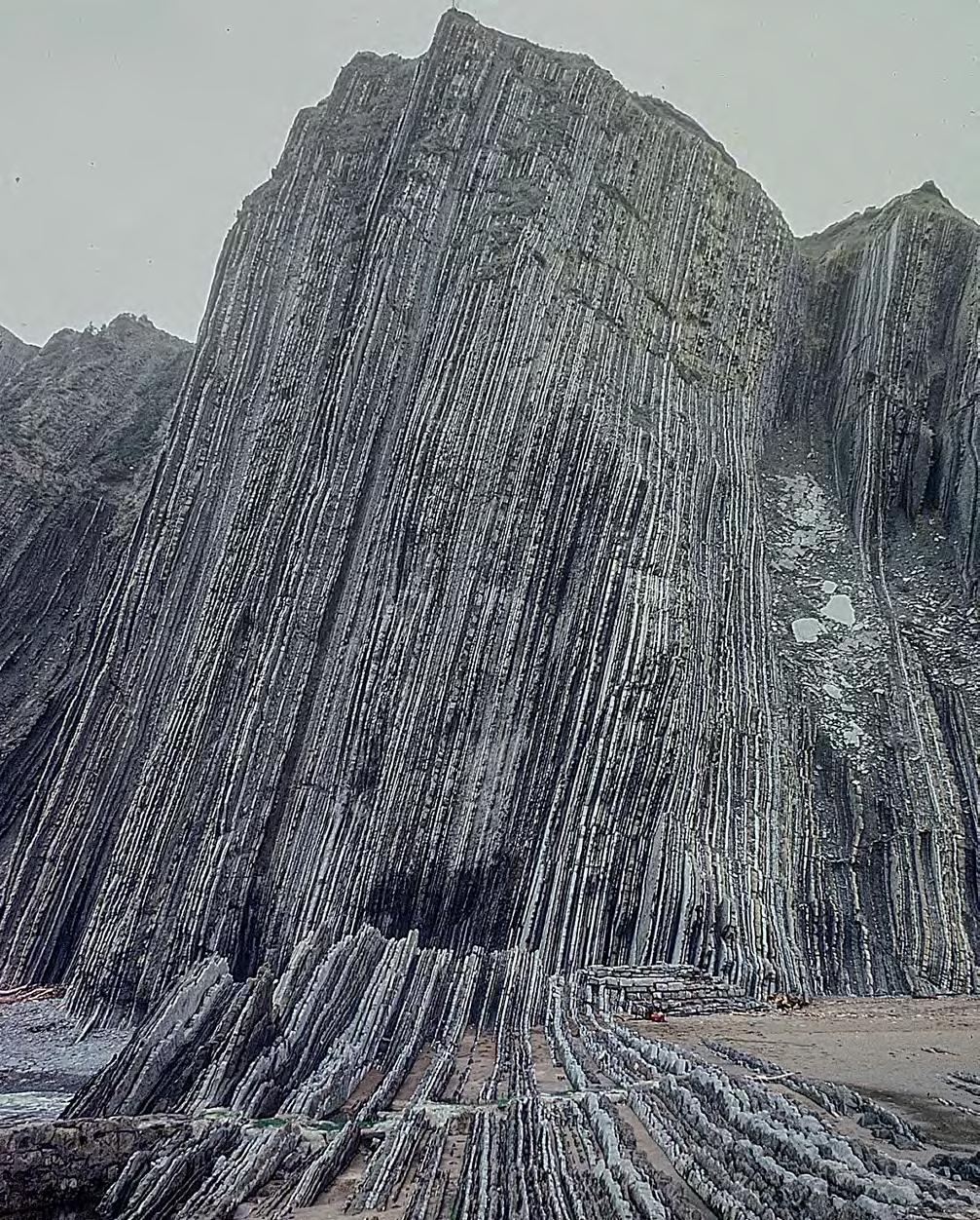
CHAPTER II: Turbidites TURBIDITE SYSTEMS: AN OUTCROP-BASED ANALYSIS 101
Fig. 68- Typical basin-plain deposits of a relatively large turbidite system: a well-known spectacular example of basin-plain turbidites consisting of alternating thin-bedded carbonates, fine-grained sandstones and mudstones (see Van Vliet, 1982). Note the even and parallel bedding pattern of basin-plain turbidites. Eocene Guipúzcoa Flysch, Basque country, Spain.
I.2 - THE BIRTH OF TURBIDITES AND THEIR GOLDEN AGE
The outcropping thick, laterally extensive and apparently monotonous marine successions made up of alternating sandstone, shaly and calcareous beds which are characteristic of many thrust-and-fold belts were originally called “flysch” by Studer (1827). The term, although carrying in itself many ambiguities, is still in use among many Alpine geologists to denote basin fills predating and/or accompanying major phases of structural deformation and dramatic paleogeographic reorganization.
The main problem with these sediments was to reconcile the alternation of sandstone beds – which in the common belief of those days were a shallow-water deposit - with shaly interbeds with open- and deep-marine fossil assemblages. Vassoevitch (1948) suggested a tectonic control on sedimentation with tectonic “ups” and “downs” at the scale of individual beds.
It was not until 1950 that a geologically more reasonable interpretation – refusing the skittish behaviour of Mother Earth with a “jo-jo” sort of process – was provided in a breakthrough paper of Kuenen and Migliorini entitled “Turbidity currents as a cause of graded bedding” (Kuenen and Migliorini, 1950). These authors proposed that the origin of graded sandstone beds in a deep-marine environment was a resedimentation process, which they called “turbidity current”, able to transfer sand and shallow-marine fossil assemblages from basin margins into adjacent deeper basins through density currents moving downslope because of their excess density. The idea was the result of field observations and laboratory experiments and a great deal of creativity. The term “turbidites” – denoting the deposit of turbidity currents – was introduced later by Kuenen (1957) following a suggestion of one of his students (C.P.M. Frijlinck). From then on, the term “flysch” gradually lost any sedimentological meaning and remained to denote a tectofacies in the evolution of orogenic belt basins.
The milestone and revolutionary paper of Kuenen and Migliorini had an enormous impact on the scientific community and dramatically changed our way of thinking in stratigraphy, sedimentology, and the relations between tectonics and sedimentation. Thousands of papers and tens of volumes and special publications dealing with many aspects of turbidite deposition have appeared over the past 60 years which would be impossible to review in depth herein.
Initially, in the 60’s and 70’s, studies were mostly concerned with the outcrop expression of turbidites and were thus carried out particularly in classic flysch basins of the Alps, the northern Apennines and the Carpathians mainly by Dutch and Polish geologists under the Kuenen’s guidance. Arnold Bouma developed his model – the popular Bouma sequence – in 1962 mainly based on field work in the Maritime Alps (Bouma, 1962).
The sequence (Figure 69 A) describes a graded bed containing five depositional divisions which, from base to top, include a basal structureless division (“a”) with coarse-tail grading, followed upward by thinly current-laminated divisions (“b” through “d”) in turn capped by a homogenous mudstone division (“e”).
Stemming from the Bouma’s cone (Figure 69 B), Parea (1965) and Walker (1967) developed the concept of proximality and distality. Many papers described in great detail the internal structures of turbidite beds and their beautiful sole markings (see Chapter I) and provided a wealth of information on paleocurrent directions from many basins, thus improving paleogeographic reconstructions. It is during this period that oustanding papers with magnificent line-drawing figures and photographic plates showed the beauty and the scientific importance of turbidite beds (e.g., Kuenen, 1957, ten Haaf, 1959; Dzulynski and Sanders, 1962). Bouma and Brouwer (1964) edited a volume containing the state-of-the-art of turbidites in their golden age.
CHAPTER II: Turbidites TURBIDITE SYSTEMS: AN OUTCROP-BASED ANALYSIS 102
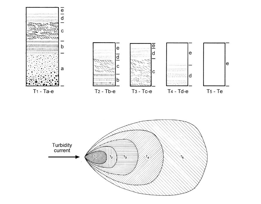
I.3 - THE “FLOWING GRAIN LAYER” OF SANDERS (1965)
Heralded by the paper of Dzulyinki et al. (1959) on fluxoturbidites, the origin of the Bouma sequence from a simple turbulent suspension started to be questioned soon after its birth. In an illuminating paper pioneering process-sedimentology, Sanders (1965) argued that the basal coarse-grained division of the Bouma sequence was in fact the deposit of an inertia flow (or flowing grain layer) impelled from the shear stress imparted by an overlying suspension, the latter being the genuine turbidity current where grains are kept in suspension by turbulence (Figure 70). The Bouma sequence was thus interpreted as the product of two distinct processes, a basal flowing grain layer (division “a”) and an overlying turbulent turbidity current (divisions “b” through “e”). An early
application of this concept was attempted by Mutti (1969) in his interpretation of the Oligocene Messanagròs Sandstone, Island of Rhodes, Greece.
II - DEEP-SEA FAN MODELS
Concomitantly with the above studies, research started moving to modern deep-water basins and marine geology thus became increasingly important to understand basin physiography and the primary role of canyons and deep-sea fans in modern turbidite sedimentation (e.g., Gorsline and Emery, 1959; Shepard and Dill, 1966; Shepard and Einsele, 1962; Haner, 1971). An extensive review of many of these problems has been recently offered by Shanmugam (2016, with references therein).
CHAPTER II: Turbidites TURBIDITE SYSTEMS: AN OUTCROP-BASED ANALYSIS 103
Fig. 69 - The Bouma sequence and its depositional cone (after Bouma, 1962).
A B
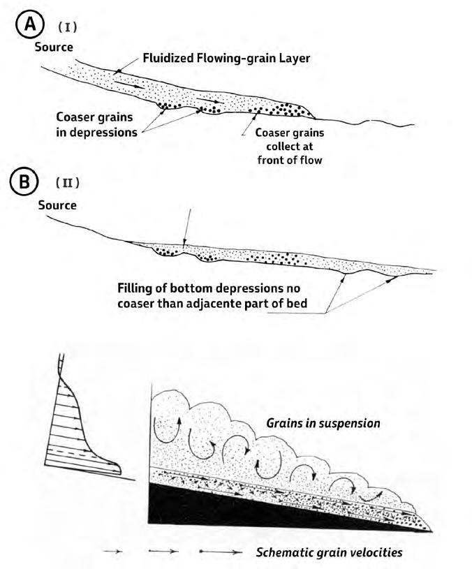
II.1 - THE SUPRAFAN MODEL OF NORMARK (1970)
The first attempt to develop a model from a modern deep-sea fan was that of Normark (1970) mainly based on his study of the San Lucas fan, off the southern tip of the peninsula of Baja California (Figure 71). The model shows a depositional lobe of sediment, or suprafan, below the short, leveed fan-valley extending from San Jose Canyon. The suprafan appears as a convex-upward bulge on a radial profile of the fan.
Based on the above study, a model for deep-sea fan growth, predicts that deposition on a fan will be localized in a suprafan at the end of large, leveed valleys
commonly found on, and generally confined to, the inner portions of deep-sea fans. The suprafan normally is on the midfan and is characterized by numerous smaller distributary channels. Rapid aggradation in the suprafan coupled with migration and meandering of the channels produces a surface marked by isolated depressions or channel remnants. Uniform deposition, producing a symmetrical half-cone morphology, results from the shifting through time of fan-valleys across the area of the fan. Coarse-grained sediment is restricted to the channelized portion of the suprafan, passing over short distance into peripheral finegrained deposits.
CHAPTER II: Turbidites TURBIDITE SYSTEMS: AN OUTCROP-BASED ANALYSIS 104
A B
Fig. 70 - The flowing grain layer of Sanders (1965).
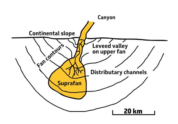
II.2 - THE CANYON-FED MODEL OF MUTTI AND RICCI LUCCHI (1972)
In 1972, Mutti and Ricci Lucchi (see also Mutti and Ghibaudo, 1972) developed a fan model primarily based on field studies from the northern Apennines and the south-central Pyrenees along with a first classification of turbidite facies and facies associations. Their fan model became very influential on subsequent studies mainly because of the clear distinction between channel and lobe elements. The model (Figure 72) suggested that most turbidite sediments contain facies associations recording deposition in slope and inner, middle and outer fan and basin-plain environments, and that these sed -
iments were typically associated with chaotic and hemipelagic facies. Based on their detailed study of the Miocene San Salvatore Sandstone in the northern Apennines, Mutti and Ghibaudo (1972) highlighted the similarities between deep-sea fans, with their channels and lobes, and fluvial-dominated delta systems, with their channels and mouth bars, and the common tendency of both types of systems to develop basinward progradation (Figures 73 e 74). The late Tor Nilsen, who had spent several months doing field work in Italy and Spain with the authors in 1974-1975, translated the original Italian version of the paper of Mutti and Ricci Lucchi (1972) into English (see Mutti and Ricci Lucchi, 1978).
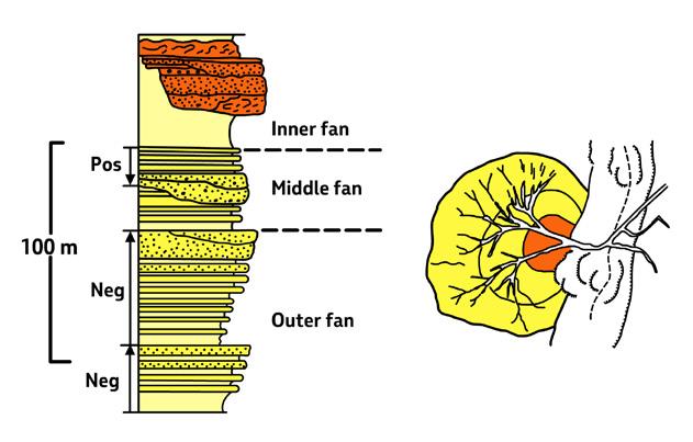
CHAPTER II: Turbidites TURBIDITE SYSTEMS: AN OUTCROP-BASED ANALYSIS 105
Fig. 71 - The suprafan model (Normark, 1970; AAPG Bulletin, v. 54, n. 11. Reprinted by permission of the AAPG whose permission is required for further use.)
Fig. 72 - The deep-sea fan model of Mutti and Ricci Lucchi (1972).

To document the applicability of the model and show that the model itself was based on actual mapping, I recently obtained the permission from ExxonMobil to show the map I prepared in 1971 for an internal research report (the research, which lasted 3 years, was carried out when I was still working for Esso Production Research Co., European Laboratories) on the Eocene Hecho Group turbidites in the south-central Pyrenees (Figure 75) – a map which I still consider as basically correct and certainly, to my knowledge, one of the very few showing an entire turbidite basin fill. The map shows the main channelised pathway, the sand-rich submarine fan complex (essentially lobe deposits), and the distal basin floor deposits (basin plain), as well as paleocurrent directions.
II.3 - FAN MODEL WITH DETACHED LOBES (MUTTI AND RICCI LUCCHI, 1974)
Later, Mutti and Ricci Lucchi (1974; see also Mutti, 1977, 1979) further suggested that outer-fan sandstone lobes could occur as depositional features detached from their feeder channels through bypass processes (Figure 76). The bypass concept was initially highly criticized by the scientific community (e.g., Stanley and Bertrand, 1979) but became widely accepted in subsequent literature (e.g., Normark and Piper, 1991; Piper and Normark, 2001; Wynn et al., 2002). They also suggested that channel and lobe facies sequences were commonly expressed by fining- and thinning-upward and coarsening- and thickening-upward trends respectively (Mutti and Ricci Lucchi, 1974), thus offering an apparently im-
CHAPTER II: Turbidites TURBIDITE SYSTEMS: AN OUTCROP-BASED ANALYSIS 106
Fig. 73 - The canyon-fed deep-sea fan model of Mutti and Ghibaudo (1972) emphasizing the similarities with fluvial-dominated deltas. Outer-fan sandstone lobes are compared with river mouth bars.
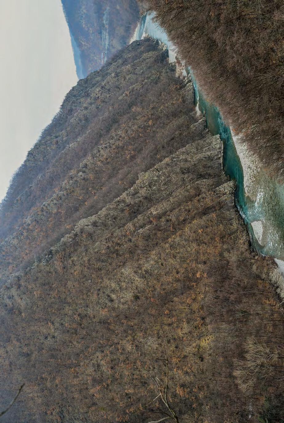
described and defined here by Mutti and Ghibaudo (1972).
CHAPTER II: Turbidites TURBIDITE SYSTEMS: AN OUTCROP-BASED ANALYSIS 107
Fig. 74The Miocene San Salvatore Sandstone in the Trebbia valley, near Bobbio, northern Apennines. Younging direction is to the right. Turbidite sandstone lobes (the relief-forming sandstone packets exposed on the left) were first
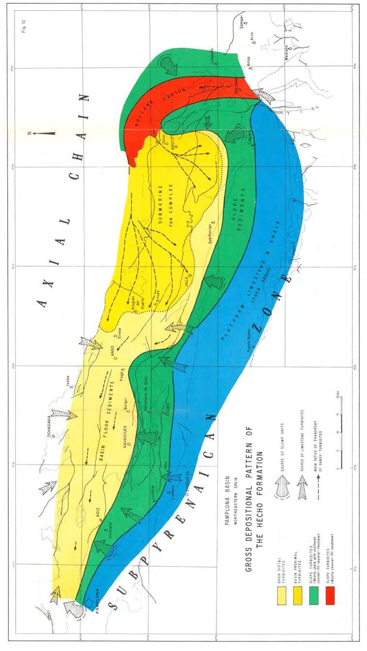
CHAPTER II: Turbidites
SYSTEMS: AN OUTCROP-BASED ANALYSIS 108
TURBIDITE
Fig. 75The first example of a mapped deep-sea fan system: the Eocene Hecho Group turbidites of the south-central Pyrenees, Spain (Mutti, 1971). Published
with the permission of ExxonMobil.
portant tool to discriminate channel and lobe deposits in well logs. The many pitfalls with these facies-trend models emerged quite soon from careful observations in the field and well-log analysis.
II.4 - THE COMPOSITE DEEP-SEA FAN MODEL OF WALKER (1978)
Walker (1978) attempted to reinterpret the facies associations of Mutti and Ricci Lucchi (1972) within the suprafan model of Normark (1970), but except for a new terminology no real improvements were made for a better understanding of the problem (Figure 77).
II.5 - DELTA-FED MODELS IMPLYING MULTIPLE CHANNELS (CHAN AND DOTT, 1983; HELLER AND DICKINSON, 1985)
The canyon-fed deep-sea fan models were challenged by Chan and Dott (1983) on the basis of their study on the Eocene Tyee and Flournoy formations in the southern and central Coast Range, Oregon. This paper doc-
umented that deltaic sands cascaded into deep-water along the edge of a narrow deltaic shelf through a series of nested channels up to 350 m wide and 40 m thick incised into fine-grained slope and shelfal deposits. These channels fed a deeper submarine fan through a line roughly corresponding to the shelfedge contrary to a single large channel or canyon (point source) of the classic deep-sea fan model. Most importantly, the new model established for the first time the close genetic relationship between fluvio-deltaic and turbidite systems. In a subsequent paper, Heller and Dickinson (1985) substantiated the model (Figure 78) and introduced the term “Delta-fed submarine ramp depositional model”. The term “ramp” was thus preferred to that of “fan”, though facies associations seem to be very similar. As discussed later, I think that delta-fed turbidite systems are the fundamental and still largely overlooked depositional setting of most deep-water systems cropping out in orogenic belt basins and probably occurring also in many continental margins with shelfedge deltas in different geodynamic settings (e.g., Carvajal and Steel, 2006).
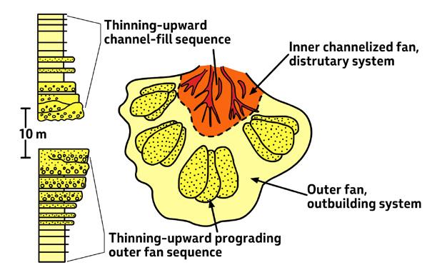
CHAPTER II: Turbidites TURBIDITE SYSTEMS: AN OUTCROP-BASED ANALYSIS 109
Fig. 76 - Fan model with detached lobes and facies sequences diagnostic of channel-fill and lobe deposits (after Mutti and Ricci Lucchi, 1974).

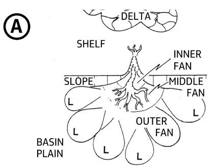
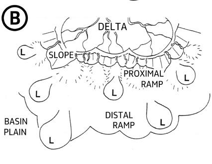
CHAPTER II: Turbidites TURBIDITE SYSTEMS: AN OUTCROP-BASED ANALYSIS 110
Fig. 77 - Composite deep-sea fan model combining the models of Normark (1970) and Mutti and Ricci Lucchi, 1972) (after Walker, 1978).
A B
Fig. 78 - The delta-fed deep-sea fan model. A. Canyon-fed deep-sea fan system B. Delta-fed deep-sea fan. Note the numerous deltaic distributaries feeding turbidite channels and lobes in proximal and distal ramp regions. The growth and the position of turbidite sediments are controlled by the lateral switching of the main deltaic distributary channels (Heller and Dickinson, 1985; AAPG Bulletin, v. 69, n. 6. Reprinted by permission of the AAPG whose permission is required for further use.)
II.6 - THE HIGHLY- AND POORLY-EFFICIENT FAN SYSTEMS OF MUTTI (1979)
The concept of flow efficiency, i.e., the ability of a flow to carry its sediment load at great distance, was introduced by Mutti and Johns (1978) and further expanded by Mutti (1979, 1992). Highly efficient systems develop from large-volume and mud-rich turbidity currents that are efficient in transporting sand over large distances because of their low rates of momentum loss, giving way to characteristic sheet-like sandstone bodies in lobe and basin-plain regions. Conversely, poorly efficient systems are built up by relatively mud-poor and small-volume turbidity currents with the common development of sand-rich bodies in proximal fan segments. The two types of system were thought to
be intergradational. The main characteristics of the two types of system are summarized in Figures 79 and 80. Volume of flows and their textural characteristics thus became important parameters in determining facies characteristics, geometry and scale of turbidite systems. With reference to highly efficient systems, Mutti (1977, 1979) addressed the problem of bypass and their sedimentary product, suggesting that highly efficient flows would undergo a hydrodynamic readjustment (hydraulic jump) at channel exits or breaks in slope resulting in residual dune-shaped bedforms essentially produced by bypassing flows. The problem is discussed at length in the following sections of this chapter since it is critical to a better understanding of turbidite elements and facies.
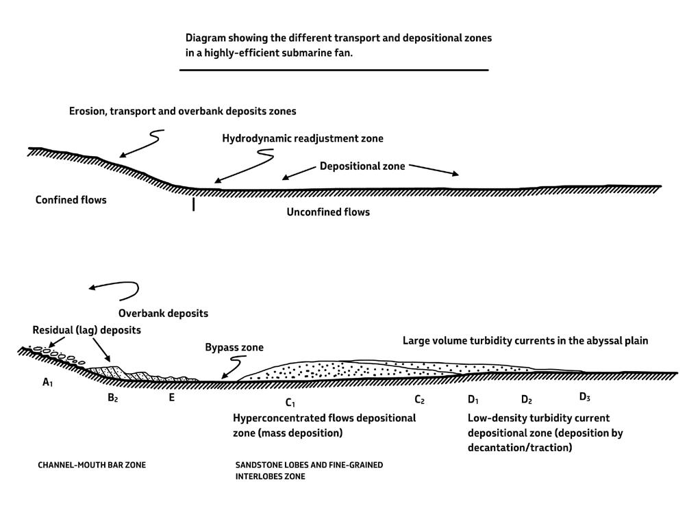
CHAPTER II: Turbidites TURBIDITE SYSTEMS: AN OUTCROP-BASED ANALYSIS 111
Fig. 79 - Highly-efficient system with bypass and detached sandstone lobes (after Mutti, 1979).
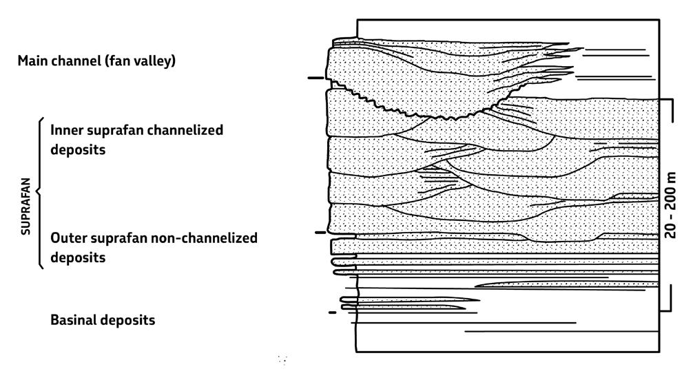
II.7 - THE COMPLEXITY OF DEEP-SEA FANS AS
REVIEWED BY RICHARD AND READING (1994)
The complexity of deep-sea fan sedimentation and the difficulties in developing general models were addressed by Reading and Richards (1994). The authors developed a detailed and exhaustive classification of both modern and ancient turbidite systems based on grain size, feeder systems and flow efficiency and recognised mud-rich point-source submarine fans, submarine ramps fed by multiple channels, and slope aprons fed by linear sources as well as all the possible transitional types. Probably, this is the most complete attempt available in the literature to describe the great variety of modern and ancient deep-water systems and the similarly varying parameters that control sedimentation. The paper includes a thourough discussion of previous literature and offers some pertinent subsurface examples of turbidite systems mostly based on well-log data.
III - ACADEMY AND INDUSTRY
All the above studies (except for my map of Figure 75) can be considered as academic efforts to understand
turbidite sedimentation. Things started to change beginning in the late 70’s with the advent of seismic stratigraphy (later sequence stratigraphy), the exploration of continental margins by industry through 2D and 3D seismic and extensive drilling, and the substantial improvements of marine geology techniques. At that point, it became clear to geologists and geophyicists that deep-water sedimentation was considerably more difficult to understand than previously thought and that, in addition to the real scientific difficulties encountered, differences in data sets and unnecessary terminology problems had started hampering communication. Both academy and industry convened at Comfan I (Pittsburgh, 1982; see Normark et al., 1983/84; Bouma et al., 1985) and Comfan II (Parma, 1988; see Weimer and Link, 1991) to discuss these new issues. Other similar meetings were organized in later years with increasing participation of industry (e.g., GCSSEPM, Fifteenth Annual Research Conference, 1994; see Weimer et al., 1994; Parma 2002; see Mutti et al., 2003a). I will expand on these problems later but clearly oil industry sedimentologists were starting to lead research either directly or indirectly providing funds to some universities. One of the main issues in most meetings has been and still is the comparison
CHAPTER II: Turbidites TURBIDITE SYSTEMS: AN OUTCROP-BASED ANALYSIS 112
Fig. 80 - Poorly-efficient turbidite system with thick-bedded lobes deposited at channel terminations (after Mutti, 1979).
between ancient and modern deep-sea fan systems, as well as the way to use the wealth of information gathered from outcrop studies to better understand the increasing complexity emerging from deep-water sedimentation of continental margins as depicted by their exploration for hydrocarbons and marine geology studies.
III.1 - THE ADVENT OF SEISMIC AND SEQUENCE STRATIGRAPHIES AND ITS IMPACT ON TURBIDITE SEDIMENTATION
Seismic stratigraphy (Vail et al., 1977) forced sedimentologists and stratigraphers to consider deep-sea sedimentation at the scale of basin fills and within cycles of relative sea level variations (depositional sequences) by introducing the concepts of highstand and lowstand of sea level. Seismic stratal patterns were used as indicators of seismic facies and the latter were interpreted in terms of deep-sea fans and bottom-current deposits. The seismic stratigraphic expression of submarine fans (lowstand fans) was described by Mitchum (1985) emphasizing the downlap terminations of individual fans and their overall mounded cross-sectional geometry (Figure 81). At the same scale, Mutti (1985) set forth a classification of turbidite systems from outcrop data derived from foreland basin fills and discussed their relations to depositional sequences. Three main types of systems were identified based on where sand is deposited, essentially as a result of decreasing volume of sediment gravity flows and their enrichment in mud and ensuing backstepping of sandy depositional zones (Figure 82). Type 1 systems are mainly made up of detached and tabular sandstone lobes; Type 2 systems are made up of of channel fills and channel-attached lobes; and Type 3 systems develop as mud-dominated features with sand deposition primarily restricted to depositional channels. Initiation of turbidity currents was thought
to be essentially related to retrogressive sediment failures of progressively smaller volume of fluvio-deltaic deposits formed during periods of sea level highstand (Figure 83).
Sequence stratigraphy (Posamentier and Vail, 1988; Vail et al., 1991) (see Chapter I) brought about fundamental concepts for basin analysis and framed turbidite deposition within the scheme of basin-floor fans (dominantly sandy) and slope fans (dominantly muddy with shingled turbidite sand units; note that the slope fan is intended in this chapter to include also the deepest water portion of the prograding lowstand complex predating the transgressive systems tract; see original definition of Van Wagoner et al., 1988) during the development of a cycle of relative sea level variation recorded by three stages: lowstand, transgressive, and highstand and their related systems tracts. A fourth stage – the falling stage systems tract formed between the onset of relative sea level fall and relative sea level lowstand (see Chaper 1) - was added later by Hunt and Tucker (1992) and Nummedal et al. (1992) (see also Plint and Nummedal, 2000). There is no doubt that the falling stage exists and can be documented by many examples; however, there seems to be some doubt that deep-water turbidites (the basin floor fan of Posamentier and Vail, 1988) develop during this stage. The falling stage actually does not consider the triggering mechnisms of turbidity currents, a basic element of the problem whose importance was starting to be appreciated (e.g., Normark and Piper, 1991). Mass-transport deposits may certainly form during the forced regressions of the falling stage as well as the early rising of sea level due to headward erosion of submarine canyons and delta slope channels, but substantial accumulations of basinal sands are more likely to form when larger drainage basins and steeper fluvial gradients are made available by the final lowstand. Most of the above problems will be amply discussed in the concluding chapter.
CHAPTER II: Turbidites TURBIDITE SYSTEMS: AN OUTCROP-BASED ANALYSIS 113
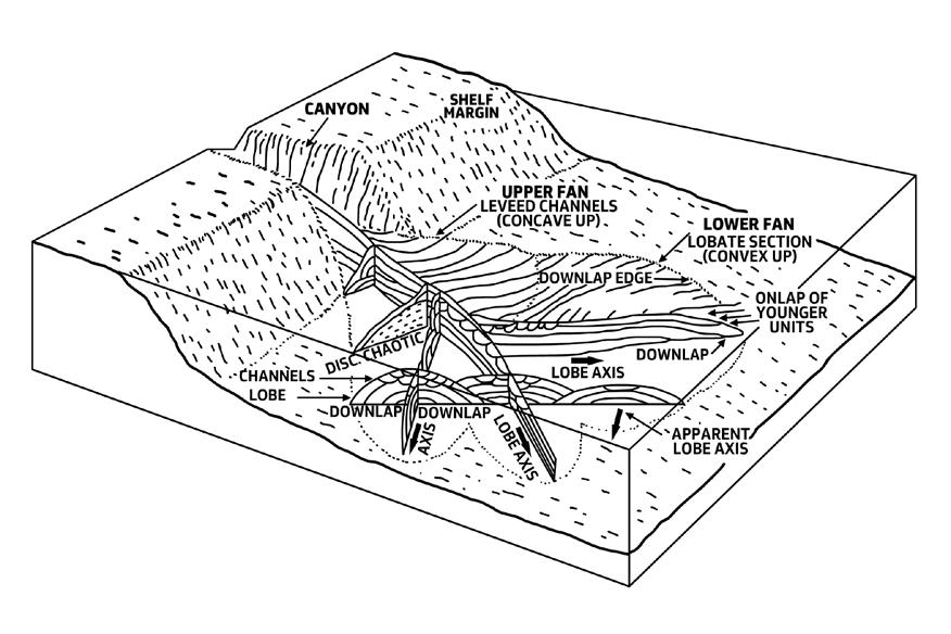
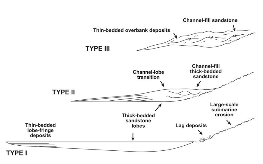
CHAPTER II: Turbidites TURBIDITE SYSTEMS: AN OUTCROP-BASED ANALYSIS 114
Fig. 81 - Seismic stratigraphic expression of a deep-sea fan. Note the mounded geometry and the downlap terminations (from Mitchum, 1985; AAPG Memoir 39, p. 117-136. Reprinted by permission of the AAPG whose permission is required for further use.)
Fig. 82 - Main types of turbidite system according to Mutti (1985). Note that sandstone lobes form at channel exit in Type II (poorly efficient systems), whereas they extend as nearly basin-wide features in Type I (highly-efficient systems).
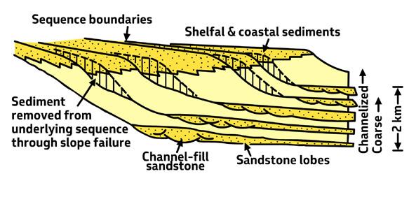
The relations of sediment supply to deep-sea fan growth, which is of great importance for the sequence stratigraphic interpretation of most ancient turbidite systems, has been addressed by Mulder and Syvitski (1995) and Mulder et al. (2003) who, in the light of flood-generated turbidity currents, postulate that eustasy-driven lowstands of sea level and wide shelves give way to very large and mature rivers that should considerably reduce the ability of floods to reach the shoreline and hence deeper marine regions. Mutti et al. (2003) have argued that this model could be reversed in case of relative sea level lowstands primarily produced by tectonic uplift of the drainage basins, which would enhance the role of floods by steepening river gradients and leading to the cannibalization of large portions of the falling stage deposits (Figure 84).
Since there is ample evidence from the Recent that high-frequency turbidity currents are being produced in many small and high-gradient settings (e.g., Bornhold et al., 1994), caution should also be exerted in assuming that there is always a direct relationship between sea level and the occurence of turbidites, though sea level lowstands have been proven to control most substantial turbidite accumulations (e.g., Shanmugam and Moiola, 1988; Normark and Piper, 1991; Reading and Richard, 1994; Steel et al., 2000).
IV - FURTHER DEVELOPMENTS
Being aware of the problems encountered when comparing modern deep-sea fans and ancient turbidite systems, Mutti and Normark (1987, 1991) drew the
attention on the many factors limiting the comparison not only between modern and ancient deposits but even between modern and modern and ancient and ancient deposits. The authors identified these limiting factors in the (1) different geodynamic settings, controlling long- or short-term stability of the basins and sediment supply; 2) scale factors, requiring that comparisons be made at similar spatial and temporal scales; and 3) different scales of observations, i.e., different data sets that result from the study of modern deep-sea fans or exposed ancient systems. These authors also attempted to frame this kind of sedimentation within a scheme of hierarchical physical and temporal scales and introduced the elemental approach. The approach, which is amply discussed in a following section on turbidite systems and their component elements, is intended to define mappable erosional and depositional elements which are common and recognizable in both Recent deep-sea fans and ancient turbidte systems. In descending hierarchical order of magnitude (physical and temporal), turbidite deposition consists of the following units (and related events): 1) turbidite complexes, 2) turbidite systems, 3) turbidite stages, and 4) turbidite substages (Figure 85 A). Among the elements introduced by these authors and further refined by Normark et al. (1993) (Figure 85 B) is the “channel-lobe transition zone (CLTZ)” that will become matter of interest and dispute in subsequent work (see later), representing the critical zone where channelized flows spread out downfan depositing their sediment load. These concepts were further refined and illustrated with many examples by Mutti (1992) and Normark et al. (1993).
CHAPTER II: Turbidites TURBIDITE SYSTEMS: AN OUTCROP-BASED ANALYSIS 115
Fig. 83 - Disintegrative failures of fluvio-deltaic deposits feeding basinal turbidite systems (from Mutti, 1985).
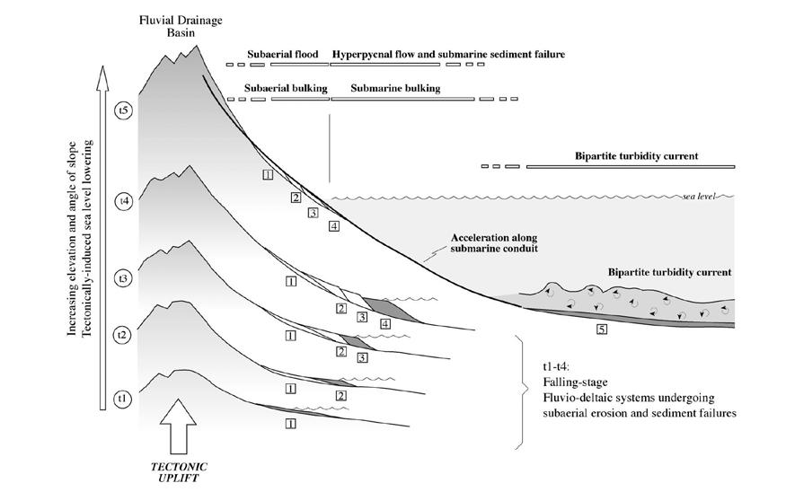
Normark and Piper (1991) analysed in great detail the many factors controlling the ignition and development of turbidity currents in modern fans, focusing in particular on sediment source and triggering mechanisms. They amply discussed turbidity currents generated by wave storms, earthquakes, and hyperpycnal flows. The authors highlighted the importance of the fjord-head deltas of British Columbia (see later) where a close relationship can be established between river floods generated by ice and snow melting and morphology and sediment types in the delta slope and adjacent deeper basin (e.g., Prior and Bornhold, 1989). They also tentatively related these different types of flow initiation to allocyclic changes such as sea level eustasy and climate. Sea level lowstand would favor direct input of fluvial sediment into deeper waters through hyperpycnal flows; canyon incision would promote slump and mass failures; during rising sea level seismic trigger of occasional thick muddy flows would predominate. Sea level variations can also affect coastal morphology, thus changing the point of sediment supply, as documented by the growth of the Monterey Fan and the relations between its feeder canyons and littoral drift.
Another important point discussed by Normark and Piper (1991) is the occurrence of large scours (giant flutes) and fields of bedforms (both coarse-grained
and fine-grained sediment waves) observed in several deep-sea fans. Scours, which have horizontal dimensions of tens to hundreds of meters and may in some instances exceed one km and have depths roughly proportional to their width, are reported from both the floors of broad turbidite channels and fan regions located immediately downslope from fan valleys and distributary channels, that is, areas where supercritical turbidity currents undergo rapid flow expansion and increased turbulence. This area essentially coincides with the element “channel-lobe transition zone” of Mutti and Normark (1987, 1991). Gravel waves with lengths of several tens of meters and heights of a few meters are reported from several modern fan valleys. Distally, these gravel waves are covered by sand ribbons and smaller sandy waves are also present in proximal lobes (“macrodunes” of Clarke et al., 1990). Similar sandy features are also reported from fjord deltas of British Columbia (Prior et al., 1987). Fine-grained sediment waves are reported from both levee complexes and open-fan regions with wave lengths up to 1.5 m and heights up to tens of meters and typically migrate upslope. Piper and Normark (1991) admit the many problems raised by sediments waves and do not rule out the possibility that bottom currents may have contributed to the formation of upslope-migrating finegrained waves.
CHAPTER II: Turbidites TURBIDITE SYSTEMS: AN OUTCROP-BASED ANALYSIS 116
Fig. 84 - Relative sea-level fall forced by tectonic uplift and its relation to lowstand basin-floor fan sedimentation (from Mutti et al., 2003).
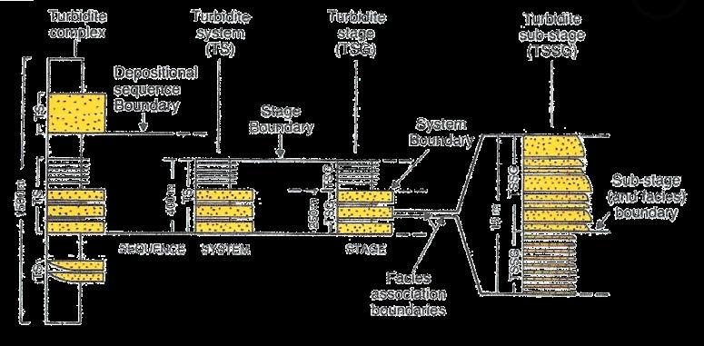
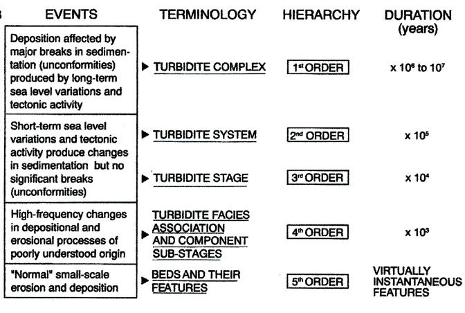
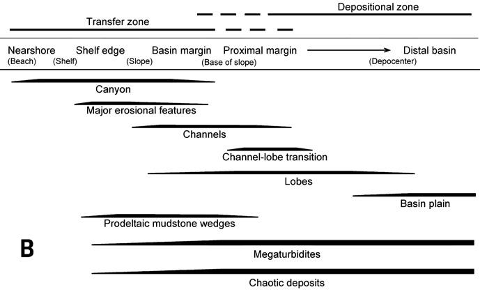
CHAPTER II: Turbidites TURBIDITE SYSTEMS: AN OUTCROP-BASED ANALYSIS 117
A B
Fig. 85 - A. Physical and temporal hierarchy of turbidite depositional units (from Mutti and Normark, 1987; 1991). B. Erosional and depositional elements as suggested by Mutti and Normark (1987) and Normark et al. (1993).
Using sea-floor morphology, bottom sediment distribution, and in-situ instrument packages, Zeng et al. (1991) have described the sea-floor sedimentation system of the Bute Inlet, a fjord of south-western British Columbia which is 70 km long, 4 km wide and reaches a water depth of 655 m. Fjord-head deltas, whose rivers are mainly fed by the annual snow melt in their drainage basins, originate turbidity currents that comprise a depositional system extending for some 70 km along the Bute Inlet. In British Columbia, as noted by Prior and Borhold (1990), delta growth started about 10.000-12.000 years ago, when fjords and adjacent areas became ice-free, and reached its maximum progradation when sea level attained its present position about 8.000-9.000 years ago. Progradation considerably increased the slope of the delta promoting transfer of sediment in deeper water.
The study of Zeng et al. (1991) describes in great detail the properties of turbidity currents (flow velocity and density) as well as some of the sediment characteristics (grain size and sedimentary structures) as observed in cores. In a down-fjord direction, the Bute Inlet turbidite system includes:
1) an incised and sinuous channel about 30 km long and 100-400 m wide, which in its lower portion contains spillover lobes, 2) a channel-lobe complex or suprafan; 3) a distal splay area; and 4) a basin-plain region, located more than 55 km from the delta front (Figure 86). Channel depth decreases down-fjord from 34 m at the base of the delta front to 6 m at the apex of the channel-lobe complex; side-scan sonar tracks show scours and transverse bedforms on the flat channel bed. The mean velocity of the most recent flows, estimated from surface sediment grain size, varies from 100-120 cm/s in the channel, to 20-50 cm/s in the channel lobe complex and to < 5 cm /s in the basin plain. Much higher velocities can be inferred for past flows. An overall substantial decrease of flow velocity can be documented or inferred at the critical transition beween channel and channel lobe complex.
The above authors suggest an origin of turbidity currents from slope failures, though admitting possible underflows. The latter are however preferred by Prior et al. (1987) and well documented (e.g., Bornhold and Prior, 1990; Bornhold et al., 1994) for this and other similar settings (Figure 87).
A very important point brought about by Zeng et al (1991) deals with core analysis. The authors show that many turbidites grade downcurrent from massive divisions (channel and channel lobe complex) into massive divisions overlain by slurried divisions (distal splay) which in turn grade into dominantly slurried beds in the basin plain (slurries are transitional flows between turbidity currents and debris flows; see later). The interpretation is that individual turbidity currents evolve downcurrent from cohesionless suspensions in the channel and the channel lobe complex to somewhat cohesive slurries in the distal splay and basin plain. Apparently, turbidity currents reaching the distal splay and basin plain contained abundant mud and clay chips eroded upstream, immediately fjordward of the channel lobe complex, which dramatically increased the flow cohesion. This kind of setting is of primary importance for a correct interpretation of shale-clast bearing and muddy-sandy divisions of turbidite facies (see later).
The results of the study of Zeng et al. (1991) have many relevant implications. The basin is relatively small and elongate, strongly resembling foredeeps of foreland basins (see later), and is sourced from one-end, with minor proportions of sediment supplied from lateral sources. The system provides an excellent example of fast-moving channelized flows that suddenly decelerate in the channel lobe complex and further decelerate moving toward the basin plain. Finally, core data indicate how flows change downcurrent from cohesionless suspensions to cohesive slurry flows substantially enriched in mud content and mud clasts through bed erosion. Most basin-plain sandstone beds are virtually entirely composed of muddy-sand divisions containing floating mud clasts.
Though primarily limited to the Amazon and the Hueneme fans, the paper by Piper and Normark (2001) provides the best integrated analysis of recent submarine fans and their different architectures and deposit types by using data from high-resolution seismic reflection surveys and DSDP/ODP wells and their detailed stratigraphy. The paper is strictly a high-level scientific contribution, but at the same time offers predictive models for exploration to locate potential reservoir sands in deeply buried turbidite systems. The elemental approach was used to describe both fans and for their comparison.
CHAPTER II: Turbidites TURBIDITE SYSTEMS: AN OUTCROP-BASED ANALYSIS 118
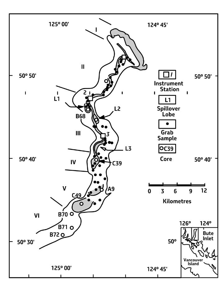
CHAPTER II: Turbidites TURBIDITE SYSTEMS: AN OUTCROP-BASED ANALYSIS 119
Fig. 86 - The major morphological subdivision and elements of the Bute Inlet system (from Zeng et al., 1991). I -Delta front; II – Incised channel without spillover lobes; III – Incised channel with Spillover lobes; IV – Channel lobe complex; V – Distal splay; VI – Basin floor.
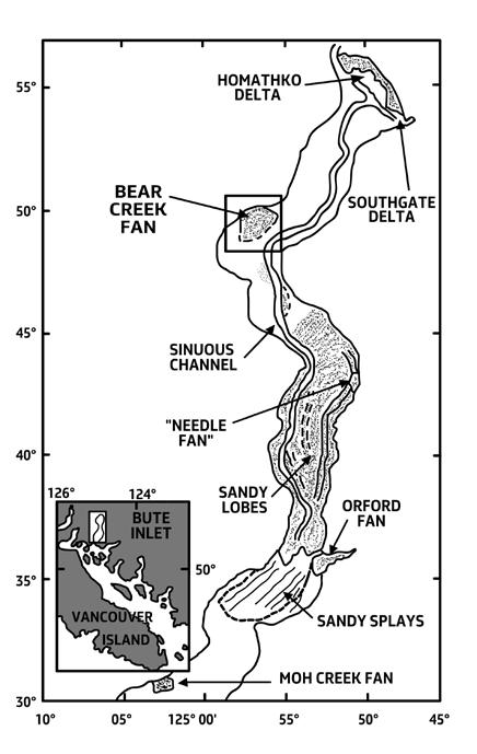
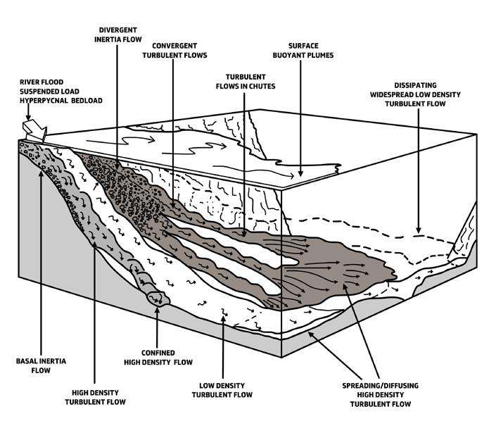
CHAPTER II: Turbidites TURBIDITE SYSTEMS: AN OUTCROP-BASED ANALYSIS 120
A B
Fig. 87 - The Bute Inlet system according to Bornhold and Prior (1989) emphasizing the role of floods in generating turbidity currents.
The Hueneme Fan is a relatively small feature (25 by 50 km) located in the tectonically active Santa Monica basin of the California borderland. Being made up of dominantly sandy elements (channel-fills and lobes), the fan can be regarded as a typical example of sandrich fan. Sands occur as 1) channel-fills within fan valleys, 2) channel-termination lobes in the middle fan passing downslope into low-gradient lobes typically 3 km wide and pinching out downdip in less than 5 km, and 3) sand-rich lower fan and ponded basin plain deposits. Careful reconstruction of the fan evolution through the past 10-12 ka permits to recognize how triggering mechanisms of turbidity currents changed repeteadily from hyperpycnal flows and river mouth failures, to rip currents in canyons, and finally to earthquake-triggered slumps in the late Holocene. Sea level variations and climate changes are thought to partly control these processes.
The Amazon Fan is a very large feature located on a divergent continental margin and fed by one of the largest rivers in the world. The fan grew rapidly during Pleistocene lowstands when, according to the authors, frequent turbidity currrents originated from prodelta failures, being unlikely that a large and mature river such as the Amazon could generate hyperpycnal flows. At sea level highs, most of the river-born sediment is transported northward by shelfal currents and the fan undergoes periods of abandonment.
The architecture of the youngest Amazon Fan suggested by Piper and Normark (2001) is shown in Figure 88 depicting a series of schematic strike sections downfan. The cross sections show very clearly how the sand:mud ratio of the youngest (last glacial cycle) levee complex on the Amazon Fan varies downfan. In the upper fan sedimentation is essentially recorded by muddy levee deposits and limited sand deposition in channel axes. Moving downfan sand deposition increases within channels and in HARP’s (high-amplitude reflection packages), i.e., relatively tabular sandstone beds confined by levee morphology and produced by channel avulsions upfan. Sheet-like sand lobes are inferred to be predominant in lower fan regions, grading into alternating mud and sand in more distal basin plain regions. Bed thickness and lateral continuity of lower fan sandstone lobes appear considerably greater than those observed upfan in the HARP element. The limited amount of sand occurring in the channels suggest a substantial bypass of most turbidity currents that probably led to the formation of detached lobes in lower fan regions. Though
based on limited data, the authors suggest that also the basin plain may be sand-rich.
Despite being generally considered as different types of fan, both the Amazon and the Hueneme show how the mixture of mud and sand supplied to a system becomes segregated during transport with sand being preferentially deposited in channels and channel-termination lobes and mud preferentially deposited in fast aggrading levee elements. The authors also briefly review other modern fan systems emphazing the huge sand accumulations found in the Escanaba trough which are thought to be associated with the Missoula megafloods and deposited in about 5 ky (between 10.8 and 15.5 ka). Sandy turbidite beds, with individual thickness between 2-12 m, extend over an area of 1300 km2 and suggest turbidity currents with run-out distance up to 1000 km. As noted by Piper and Normark (2001), erecting deep-sea fan models of general validity is highly premature not only because of the differences in available datasets, but especially because a better appreciation is needed of the many parameters controlling the growth of each fan in terms of source characteristics, initiation processes and flow evolution of the turbidity currents, together with the tectonic setting controlling shape, size and depth of the basin.
Wynn et al. (2002) expand on the channel-lobe transition zone (CLTZ) of Mutti and Normark (1987, 1991) describing similar settings from the recent Agadir Channel mouth, the Lisbon Canyon mouth, and the Rhone Fan, and briefly discussing other possible examples from both recent and ancient depositional systems. Mainly based on high-resolution side-scan sonar imagery, the author recognizes various types of scour, spoon- and chevron-shaped, which may amalgamate forming erosional features several km across, as well as depositional bedforms or sediment waves with wave lengths of 1-2 km and wave heights up to 4 m. Following Mutti and Normark (1987, 1991), the authors interpret these features as primarily produced by hydraulic jumps suffered by turbidity currents at channel exits and breaks of slope, resulting in increased turbulence, bed erosion and sediment bypass. The authors strengthen the difficulties in defining and mapping the CLTZ since variations in turbidity current volume will shift the location of any hydraulic jump within the system. Wynn et al. (2002) refine the model of highly- and poorly efficient systems of Mutti (1979) restricting the concept of the CLTZ to highly efficient systems. As discussed later, the CLTZ actually characterizes both systems, albeit with different expressions.
CHAPTER II: Turbidites TURBIDITE SYSTEMS: AN OUTCROP-BASED ANALYSIS 121
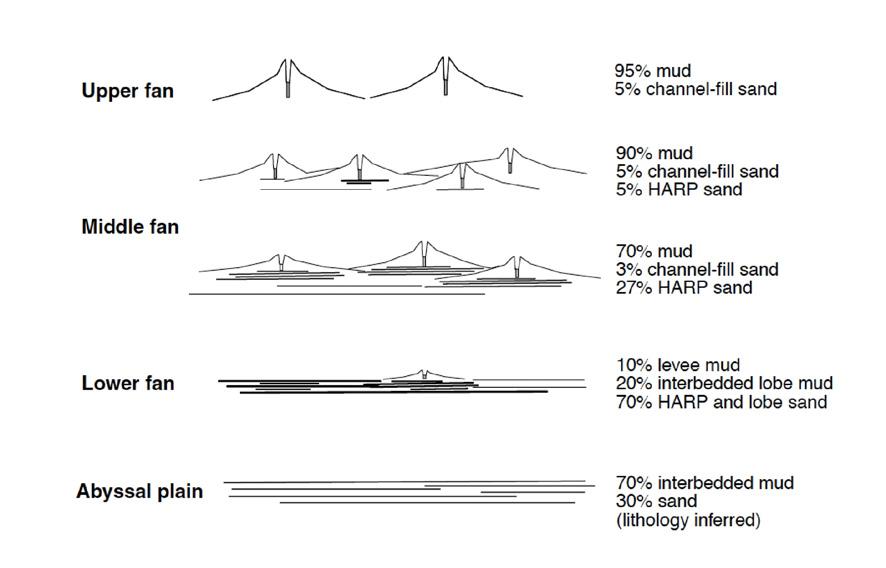
Deptuck et al. (2008) have provided a very well-documented example of the growth and geometry of sandstone lobes in late Pleistocene relatively small and sandrich deep-sea fans off East Corsica (Figure 89). Based on 1300 line km of high-resolution (0.5 m) boomer profile supplemented by core data, the authors describe in great detail the Golo fan system consisting of several interfingering submarine fans fed by large shelf-indenting canyons and slope gullies. These fans are located in a shallow (< 900 m) and narrow (< 50 km) fault-bounded depression with a length of about 150 km known as the Corsican Trough. The basin in bounded by a narrow shelf and is fed by small and high-gradient rivers. The
fans are dominated by sandy lobes, with limited development of levees and basin plain deposits.
Two basic types of lobes can be identified: 1) proximal isolated lobes (PILs) located on the slope o near the base-of-slope and fed by slope gullies (the Pineto lobe-type); and 2) composite mid-fan lobes (CMLs) developed more basinward at the termination of leveed fan valleys (the north Golo lobe-type). The Pineto lobe reaches a maximum thickness of 19 m near the toe-ofslope and abruptly decreases in thickness to 1.5 m over a distance of about 6 km (Figure 90). This kind of lobes formed during the last transgression and were probably fed by small sediment failure and surge-type flows.
CHAPTER II: Turbidites TURBIDITE SYSTEMS: AN OUTCROP-BASED ANALYSIS 122
Fig. 88 - Architecture of the youngest Amazon fan in a series of downfan strike sections showing variations in the sand:mud ratio (from Piper and Normark, 2001).
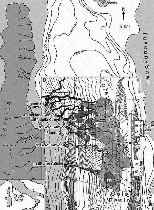
CHAPTER II: Turbidites TURBIDITE SYSTEMS: AN OUTCROP-BASED ANALYSIS 123
Fig. 89 - Relatively small and sand-rich Pleistocene canyon-fed deep-sea fans on the eastern continental margin of Corsica (from Deptuck et al., 2008).
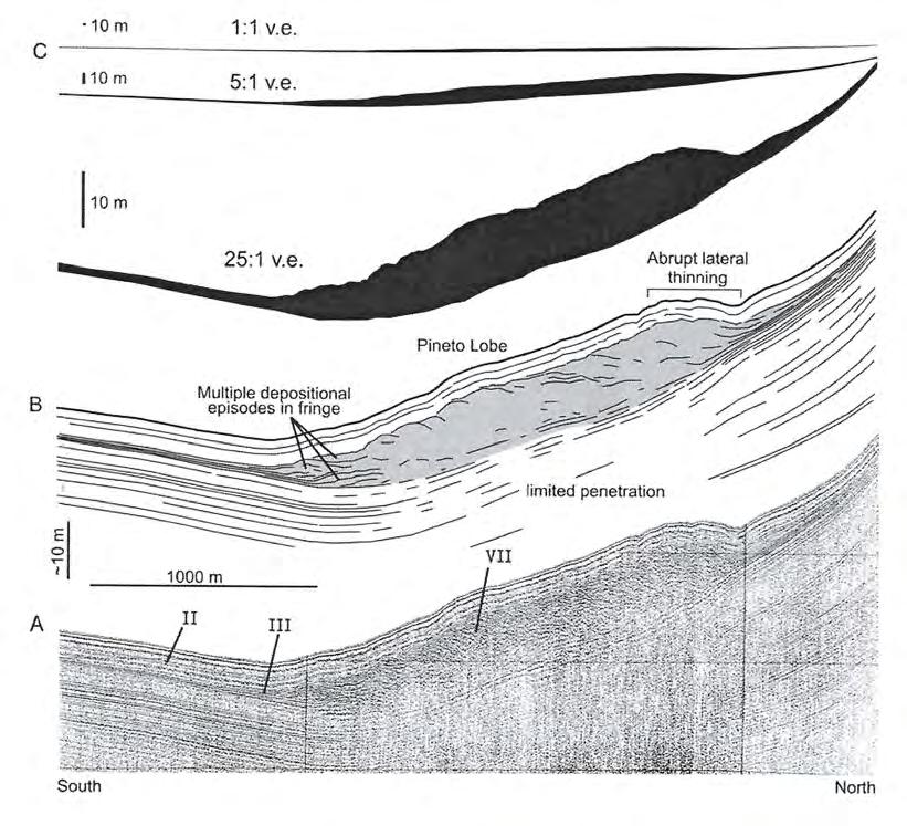
The CMLs lobes are larger and more tabular feaures, or composite lobes, formed from the stacking of lobe elements, that reach a maximum thickness between 25-40 m at the exit of fan valleys and can be correlated over distances between 8-14 km beyond the fan valley mouth. Scours and possible coarse-grained bedforms are associated with the distal fringes of these sediments, possibly indicating - in this writer’s opinion -, local conditions of sediment bypass for more vigourous currents. Notewhorty is the presence of backstepping reflections near the fan valley
mouth, a feature that according to the model of Postma et al. (2016) may be indicative of supercritical turbidity currents and related hydraulic jumps in channel-lobe-transition settings (see later). The CMLs lobes are interpreted as lowstand deposits mainly fed by hyperpycnal flows.
Deptuck et al. (2008) also discuss at length the compensational stacking of lobe deposits, suggesting a new terminology and a hierarchical classification (Figure 90 A).
CHAPTER II: Turbidites TURBIDITE SYSTEMS: AN OUTCROP-BASED ANALYSIS 124
A B C
Fig. 90 - The Pinedo lobe. Note that without vertical exaggeration the sandstone body is basically tabular (C), showing an abrupt thinning upslope and a gradual pinching-out basinward (from Deptuck et al., 2008).
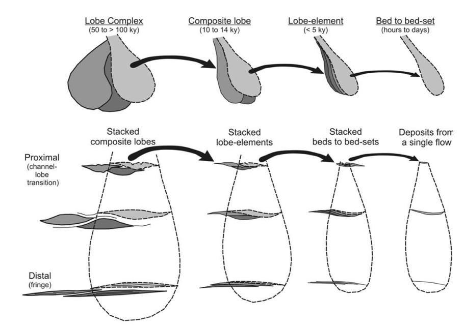
As mentioned above, Postma et al. (2016) have recently offered a quite revolutionary approach to the study of deep-sea fans and turbidite systems. The approach is fundamentally based on flow criticality and is “aimed to resolve process-facies links at both bed and environmental scales for the CLTZ” (op. cit., p.469). The supporting outcrop data are from two examples studied in the Tabernas submarine fan (southern Spain) and the Lorenc del Munt fan-delta (Catalonia, Spain) and are used to establish a link between seismic scale architecture and facies recognized in cores. Though I may fully agree that flow criticality is fundamental for turbidite facies analysis (see later), I honestly think that a new model of fan sedimentation based on the available data on supercritical turbidity currents is somewhat premature.
Despite the difficulties outlined above, in recent time there has been a vigorous revival of canyon-fed deepsea fan models, largely promoted by the availability of high-quality seismic-reflection and marine geology datasets. This tendency is typified by the scheme for deep-water sedimentation offered by Posamentier and Walker (2006). The contribution is primarily based on seismic reflection and marine geology data and emphasizes the importance of levee and channel elements associated with lateral and frontal splays (lobes in most previous literature). Compared to the complexity encountered in the real world and the variety of depositional settings displayed by modern and ancient turbidite systems (see above), the model seems of limited general validity.
CHAPTER II: Turbidites TURBIDITE SYSTEMS: AN OUTCROP-BASED ANALYSIS 125
Fig. 90 A - Terminology and hierarchy of compensational stacking patterns of sandstone lobes (from Deptuck et al., 2008).
V - SOME CONCLUDING REMARKS
In my opinion the main problems with turbidites are still basically those discussed at a workshop held in Parma in 2002 and summarized in a special issue of Marine and Petroleum Geology (Mutti et al., 2003): (1) the tendency to mix data and interpretations from outcrop studies of orogenic belt basins and subsurface data and interpretations from divergent margin basins (mostly base on seismic reflection data); in most cases datasets are not comparable; (2) the lack of studies that cover an entire basin or substantial portions of it to partly understand the well-known problem “from source to sink” and the depositional and stratigraphic relationships of turbidites with coeval fluvio-deltaic systems; (3) an extremely complex and confusing terminology; (4) the tendency to produce facies classifications based mostly on processes and terminology rather than on rocks (see later); and (5) the tendency to overlook the importance of bottom currents in reworking and redistributing turbidite sands in many basins, particularly in oceanic settings.
In an illuminating paper, Milliman and Sivitsky (1992) highlighted the basic differences of fluvial systems in active and passive continental margins, emphasizing the role of small and medium size “mountainous rivers” in dramatically increasing sediment flux to the sea. Mulder and Syvitsky (1995) further explored this problem showing that hyperpycnal flows generated by small and high-gradient rivers in flood (their “dirty rivers”) become turbidity currents that are able to transfer river-born sediment directly to deep-waters. Mutti et al. (1996, 2000, 2003) used outcrop data to show that flood-dominated fluvial systems comprise a dominant component of the alluvial and deltaic successions of orogenic belt basins and documented the direct relationships between certain types of turbidite systems and their feeder flood-dominated fluvial and deltaic equivalents. These problems are amply discussed in the final chapter of this book. Heralded by the papers of Chan and Dott (1983) and Heller and Dickinson (1985), delta-fed turbidite systems – the “ramp model” with multiple feeder channels incised into the delta slope (see above) – appear to be common in orogenic belt basins (see above) and related to the high rates of sediment flux to the sea of the “mountainous rivers” of Milliman and Sivitsky (1992).
Basically, the above considerations demonstrate the need for reconsidering turbidite sedimentation within
a broader depositional framework including its shallow-water feeder systems – a problem already stressed in Chapter I. Significant basin analysis should compare these two kinds of sedimentation in an attempt to recognize how different types of basinal turbidites can be recognized on the basis of the characteristics of their related shallow-marine deposits and, therefore, of different triggering mechanisms of turbidity currents. A better understanding of the well-known problem “from source to sink” (see discussion in Mutti et al., 2003b) heavily depends on this kind of basin analysis.
A second and important point comes from the discovery that large portions of the late Cretaceous and Tertiary sands producing oil in the Brazilian offshore are not turbidites as previously thought but contourites, i.e., bottom-current deposits whatever the origin of the currents (Mutti and Carminatti, 2012). This finding carries in itself several implications for exploration and production. Sandy contourites and turbidite sands reworked by bottom currents form important reservoirs for petroleum accumulations and this is an unexpected new target for industry. At the same time, bottom currents and contourites – thought to be essentially thin, fine-grained and bioturbated deposits in previous literature (e.g., Stow et al., 2002; Stow, 2005) – become an extremely important element for the interpretation of the stratigraphic and depositional settings of many continental margins (Mutti et al., 2014; Capella et al., 2017).
VI - WHAT CAN BE LEARNT FROM EXPOSED TURBIDITE SYSTEMS OF FORELAND BASINS
VI.1 - GENERAL
Most of what we know about turbidites is derived from exposed systems of tectonically-mobile basins where the concept of “flysch” – the forerunner of turbidites –was born long time ago (see Mutti et al., 2009). Sandy flysch like the Macigno and Marnoso-arenacea (northern Apennines), the Hecho Group (south-central Pyrenees) and the Annot Sandstone (French Maritime Alps) are certainly among the turbidite basin fills that have substantially contributed to a better knowledge of this kind of sedimentation.
I will therefore review in this section some of the basic features of these basin fills in the attempt to partly understand how far we can go in their comparison with modern and buried deep-sea fans located in different geodynamic settings and the many models that de-
CHAPTER II: Turbidites TURBIDITE SYSTEMS: AN OUTCROP-BASED ANALYSIS 126
scribe them. The review is limited to ancient foreland basin fills, that is the basins that most contributed to our knowledge of ancient turbidites. For an extensive review of turbidite basin fills of other kinds of tectonically mobile settings the reader is referred to Pickering and Hiscott (2016).
VI.2 – FORELAND BASIN TYPES
With specific reference to the northern Apennines and the south-central Pyrenees, with which I am most familiar, turbidites are found in three basic settings associated with the develoment of foreland basins and related orogenic wedges (Figure 91). Following the scheme suggested by Mutti et al. (2002), turbidite deposition in foreland basins occurs in three distinct domains, each being defined by a specific tectonic setting and basin geometry. As shown in Figure 91, turbidites essentially occur in 1) wedge-top basins, 2) piggy-back basins, and 3) foredeeps.
Thrust-top basins form in the deeper portions of structurally induced depressions and unconformably overly, with or without intervening alluvial and shallow-marine deposits, highly tectonically deformed
units of the orogenic wedge. These basins are filled by sand-rich and immature turbidites (poorly efficient systems) with abundant conglomerates and mass transport deposits and are characteristically associated, both vertically and laterally, with flood-dominated and coarse-grained flood-dominated deltas and fan-deltas.
Typical thrust-top successions are those of the Tertiary Piedmont Basin, northwestern Italy (e.g., Mutti et al., 2002), and the Tertiary Epiligurian basins (e.g., Ogata et al., 2012; Tinterri et al., 2015), formed during the inception and the development of the northern Apennines thrust-and-fold belt. Though with some caution, these basins share many characters with the intra-slope basins produced by salt and mud mobility in above-grade slopes of divergent continental margins (see Prather, 2003).
Foredeeps are the classic turbidite basins of orogenic belts formed in highly subsiding and elongate troughs developed in front of an advancig and growing orogenic wedge. Their subsidence is thought to be produced by the loading of the orogenic wedge (flexural subsidence) and/or to more complex geodynamic settings involving deeper crustal levels.
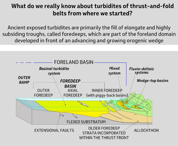
CHAPTER II: Turbidites TURBIDITE SYSTEMS: AN OUTCROP-BASED ANALYSIS 127
Fig. 91 - Ancient exposed turbidites are primarily the fill of elongate and highly subsiding troughs, called foredeeps, which are part of the foreland domain developed in front of an advancing and growing orogenic wedge (from Mutti et al., 2002).
Except for their inner portion where thrusting and folding progressively scrape-off and incorporate foredeep strata into the advancing thrust front and creates much structurally-induced topography and related sub-basins (inner foredeeps or piggy-back basins, see Tagliaferri and Tinterri, 2016 for the Firenzuola basin of the Marnoso-areneacea), the axial foredeep is relatively undeformed and allows for the deposition of impressively tabular strata over distances up to tens and hundreds of km. These sheet-like deposits are essentially the outer fan lobes, fan-fringe and basin plain facies as described by Mutti and Ricci Lucchi in 1972.
Certainly, the best-known examples of this kind of sedimentation are the Miocene Marnoso-arenacea (MA) of the northern Apennines and the Eocene Hecho Group of the south-central Pyrenees. Both basins formed in a context of continent-to-continent collision, are elongate parallel to thrust fronts and in their early development were filled from one end and supplied from extra-orogenic source areas. In the early phases of their development, basin margin contributions to the basin fills are strictly limited to chaotic deposits derived either from the thrust front, still largely subaqueous, or from the outer foreland ramp. The fills of both the MA and the Hecho Group basins share many similarities in terms of geometry of sandstone bodies and facies characteristics. Largely stemming from original work of Ricci Lucchi and co-workers (e.g., Ricci Lucchi and Valmori, 1980) in the MA and Mutti et al. (1988) in the Hecho Group extensive and detailed field studies were carried out in both basins in recent years (Remacha et al.,2003; Remacha and Fernandez, 2005; Amy and Talling, 2006; Magalhaes and Tinterri, 2010; Tinterri and Magalhaes, 2011, Sumner et al., 2012). Spectacular exposures and the occurrence of very distinctive key beds (calcareous megaturbidites) allow for impressive bed-by-bed correlations within turbidite systems over distances of several tens of km. No doubt, foredeep turbidites are essentially sheet-like deposits with local anomalies clearly produced by subtle topographic highs produced by ongoing structural deformation and the onset of basin margin-derived chaotic units. Buried systems of this kind have also been document-
ed by Ghielmi et al. (2013) for the Po Plain-Adriatic foredeep of the northern Apennines during late Pliocene-Pleistocene time.
Outer foredeep deposits form where turbidites onlap the outer margin of the axial foredeep.
VI.3 – MAIN CHARACTERISTICS OF FORELAND BASIN TURBIDITE SEDIMENTATION
Turbidite sedimentation of foreland basins differ substantially from that described from other types of continental margins, especially those located in stable divergent ones and fed by large rivers. In particular, they form basin fills that either irregularly shaped by ongoing structural deformation (faults and folds) in thrusttop and inner foredeep (piggy-back) basins or elongate for considerable distance parallel to thrust fronts in the foredeeps. Compared to divergent-margin settings, basins are small and, being based on less subsiding continental crust, probably also developed at shallower water depths. Some foredeeps may extend longitudinally up to some hundreds of km; some thrust-top basins may be only few km across.
Tectonic mobility creates short-term variability in depocenter location and source areas. In foredeeps, longitudinal supply from one-end may be replaced with time by lateral supply from basin margins, particularly from the tectonically unstable inner margin, leading to the “cannibalization” of previously deposited turbidites incorporated in the advancing orogenic wedge.
As indicated in Figure 92, largely inspired from the Marnoso-arenacea Formation, long-term evolution of basin fills is strongly controlled by the growth and outward displacement of the orogenic wedge, with resulting outward shifting of sand depocenters and dramatic changes in depositional style. The result could be described as an overall tectonically forced regression. A very detailed study of Tinterri and Tagliaferri (2015) discusses the main stratigraphic and sedimentological features of this kind of tectonically controlled evolution for the transition between the inner and outer foredeep of the Miocene Marnoso-arenacea.
CHAPTER II: Turbidites TURBIDITE SYSTEMS: AN OUTCROP-BASED ANALYSIS 128
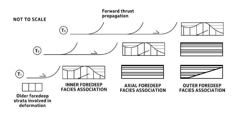
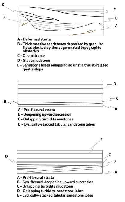
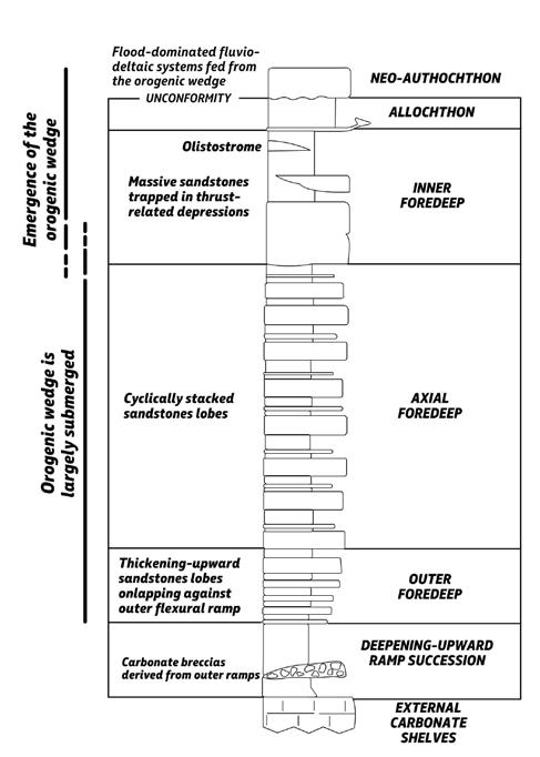
CHAPTER II: Turbidites TURBIDITE SYSTEMS: AN OUTCROP-BASED ANALYSIS 129
Fig. 92 A - Idealized cartoon showing the fill of a foredeep basin resulting from thrust-related depocenter migration with time (not to scale) (from Mutti et al., 2002).
As noted by Mutti and Normark (1987, 1991), another important and commonly overlooked difference with ocean-facing continental margins certainly resides in the fact that foreland basins are too small and tectonically isolated to be reached by large-scale oceanic circulation and, therefore, by bottom currents, which are increasingly reported as a fundamental process in reworking turbidite sands and building up substantial contourite sand bodies (see above). The problem, which I believe is of basic importance for a better understanding of deep-water sedimentation, is amply discussed in the final chapter of the book.
Setting aside geodynamic and physiographic settings, scale and planview geometry, these turbidite systems share nonetheless many characterisics with modern deep-sea fans, in that in both cases sedimentation occurs via conduits and terminal sand lobes grading in turn into more or less developed basin plains. These similarities led to conclude that turbidites of this kind could be interpreted by assuming modern deep-sea deep-sea fans as a model
(Mutti and Ricci Lucchi, 1972). It was not until 1983, at COMFAN I, that turbidite sedimentologists became fully aware of the difficulties in maintaining this assumption and tacitly agreed on introducing the more neutral term “turbidite systems” (Bouma et al, 1985).
Barnes and Normark (1985) presented an impressive wall chart (Figure 93) showing the differences in scale of a significant number of both modern deep-sea fans and ancient and exposed turbidite systems from orogenic belt basins. Inspection of Figure 93 shows how some foreland-basin systems compare with large modern deep-sea fans. Figure 94 shows a comparison between the size of the Eocene Hecho Group basin fill of the south-central Pyrenees and the Congo deep-sea fan. The differences are somewhat striking and should suggest caution in making comparisons. Nonetheless, useful comparisons can be made following the elemental approach of Mutti and Normark (1987,1991) if carefully constrained by comparable physical and temporal scales and the inherently different datsets (see below).
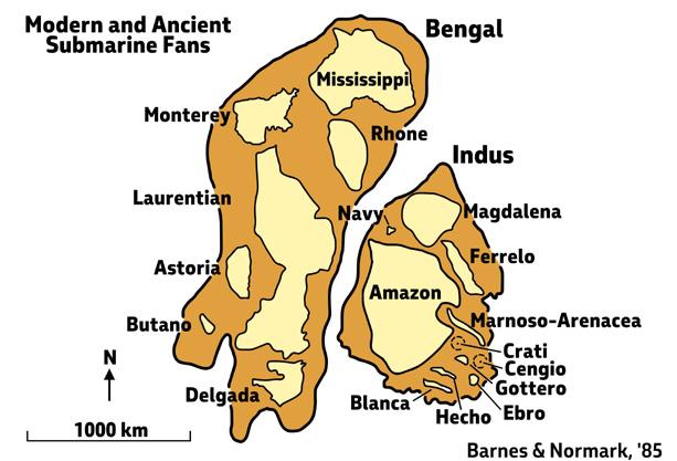
CHAPTER II: Turbidites TURBIDITE SYSTEMS: AN OUTCROP-BASED ANALYSIS 130
Fig. 93 - Chart comparing some modern deep-sea fans and ancient turbidite systems (from Barnes and Normark, 1985).
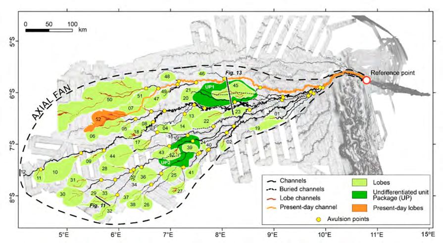
VI.4 – TURBIDITE SYSTEMS AND THEIR COMPONENT STAGES AND ELEMENTS
VI.4.1 - Definitions and general schemes
Turbidite systems are mappable turbidite accumulations that usually grow through distinct stages and substages and are characterized by internal erosive and depositional elements. In its most simple expression, a system consists of a basal sandy stage followed by a muddier stage formed following a decrease in the sand supply. In basinal settings, turbidite systems may stack to form turbidite complexes; within each system, turbidite stages can be further subdivided into m- to dam-thick substages recording high-frequency variations in depositional patterns largely associated with orbital cycles. High frequency cyclicity, sometimes recorded by spectacular alternations of sub-stages in both channelized and tabular deposits (Figure 94 A), is one of the most pervasive features observed in turbidite strata and is therefore present in all elements
discussed in later sections. These concepts are summarized in the actual example of Figure 95 from the Proterozoic Zerrissene Sandsone, Namibia, and are amply discussed by Mutti and Normark (1987, 1991), Mutti (1992) and Mutti et al. (1999, 2009).
Once a system and its main stages of growth have been recognized and mapped in outcrop or subsurface studies, by using a simple lithologic approach or seismic and well-log characteristics, the further step is the definition of its basic component elements. As intended herein, elements can be considered as the objective and “anatomic” components of a depositional system and a system can thus be defined as an association of two or more genetically related elements. The two basic elements include a sediment pathway and a depositional zone. Whatever the scale and the depositional setting, these two elements can be recognized in the great majority of turbidite systems.
CHAPTER II: Turbidites TURBIDITE SYSTEMS: AN OUTCROP-BASED ANALYSIS 131
Fig. 94 - Channel-lobe map of the late Quaternary Congo Fan established from bathymetric and seismic data (from Picot et al. 2016) and comparison with the total length of the Eocene Hecho Group, south-central Pyrenees.
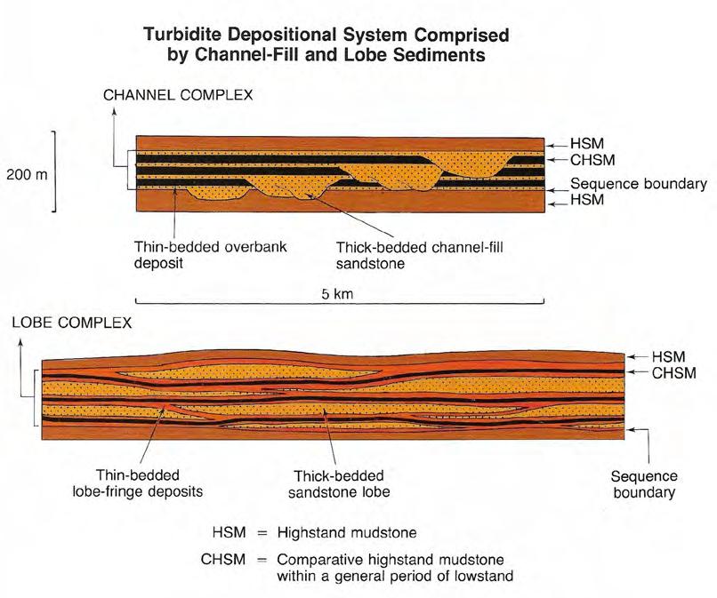
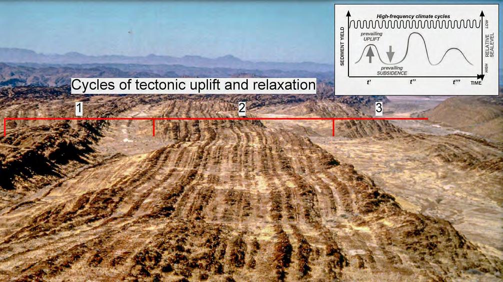
CHAPTER II: Turbidites TURBIDITE SYSTEMS: AN OUTCROP-BASED ANALYSIS 132
Fig. 94 A - High-frequency stacking pattern of channel-fill and lobe complexes at the sub-stage scale. Note the compensational stacking pattern of sandstone lobes (from Mutti, 1985).
Cycles of tectonico uplift and relaxion 1 2 3
Fig. 95 - The spectacular exposure of the Proterozoic Zerrisene turbidite sandstone lobes in the Nabib desert showing cyclic stacking patterns at different physical (and temporal) scales. Younging direction from left to right. Note high-frequency cyclicity (EDSs) superimposed on long-period cycles of base level variations (from Mutti et al., 2009).
The approach defines a limited number of erosional and depositional elements that are relatively easy to recognize and map in outcrop and seismic-reflection studies, thus allowing a significant comparison of a variety of systems, both ancient and modern. An additional further step, which can be undertaken only through detailed outcrop and core facies studies, leads to the “physiologic” understanding of depositional systems and their component elements, i.e., the processes which control the way rocks form and vary in space and time thus allowing reasonable prediction. As in the human body, anatomy describes the component pieces and the way they are assembled; physiology takes care of understanding how these pieces work together and how we are thus alive. It will be noted the fundamental difference between “anatomic” and “physiologic” elements as used herein and the “architectural” elements of Miall (1985) which best fit the concepts of facies and sandbody geometry (see also Miall, 1989, and Clark and Pickering, 1996).
The main elements, both erosional and depositional, indicate that turbidite deposition is basically controlled by conduits, or sediment pathways, along which sediment gravity flows are accelerated and transferred basinward and by lobe and basin-plain elements where flows decelerate and progressively deposit their sediment load. An ideal turbidite depositional system, consisting of a conduit and an unconfined depositional zone is shown in the diagram of Figure 96. This conceptual scheme should be considered only as a way of thinking that should be adapted to local conditions, particularly basin size and configuration which are controlled by the type of local and regional tectonic setting, type of sediment source, and volume, textural composition and triggering mechanisms of sediment gravity flows (see later). Figure 97 shows a dipsection of an ideal highly-efficiency system with a channel-lobe-transition zone formed upcurrent of laterally extensive basinal sandstone lobes.
Basically, turbidite systems can be viewed as fluvial systems as intended by Schumm (1977), that is systems consisting of a source zone that provides sediment and water, a transfer zone along which sediment and water are transferred downstream, and a depositional zone where the process comes to an end through final deposition. The analogy is striking if the assumption is made that these systems can be fed directly by hyperpycnal flows (cf. fluvio-turbidite systems of Mutti et al., 1996; Chapter I). The analogy is still valid if the source zone is identified in the combination of fluvial floods and concomitant failure and remobilization of
normal inter-flood river-mouth deposits. The analogy loses some strength if the source zone is identified in sediment failures on prodeltaic slopes, also because in this case failures should be retrogressive to intercept and remove sands in inner delta-front regions as well as long-lasting enough to account for the great number of events that characterize turbidite depositional units. Large catastrophic failures and MTDs are not a likely triggering mechanism because of their low frequency and their apparent difficulties in transforming in turbidity currents.
The main elements which can be recognized in turbidite systems are shown in Figure 98 and briefly discussed below. Erosional elements are erosional features, essentially canyons, fan valleys, channels and scours; depositional elements include a variety of turbidite accumulations ranging from the fill of erosional features to transitional deposits between erosional and depositional settings (channel-lobe transition element), and to fully depositional elements such as lobe and basin-plain elements. Channel-levees are an important element of many large systems produced by both erosion (channel) and lateral deposition through overbanking. Their presence largely depends upon the volume of flows and the amount of fines they carry in suspension (see later).
VI.4.2 – Slope sediments
Setting aside canyons and delta-slope channels, incised into the slope and forming the erosional elements of more basinal turbidite accumulations, as well as the sandy infill of intraslope minibasins in tectonically mobile settings, most slope deposits are recorded by mudstone-dominated facies which have generally received little attention. These sediments are conversely very important particularly in those cases where basinal turbidite sedimentation is fed by deltaic systems developed on the shelf or the shelfedge via hyperpycnal flows. An understanding of these sediments is thus critical for the so-called “source-tosink” problem.
Below I will briefly describe some of the main features of a spectacularly exposed slope succession in the Eocene foreland basin of the south-central Pyrenees (see Mutti et al., 1988, 2003) (Figure 99). These slope sediments record the link between flood-dominated deltaic systems and an adjacent turbidite basin, comprising thick sedimentary wedges thinning out in a basinward direction and separating turbidite sandstone wedges thinning out in a landward direction (Figure 100).
CHAPTER II: Turbidites TURBIDITE SYSTEMS: AN OUTCROP-BASED ANALYSIS 133
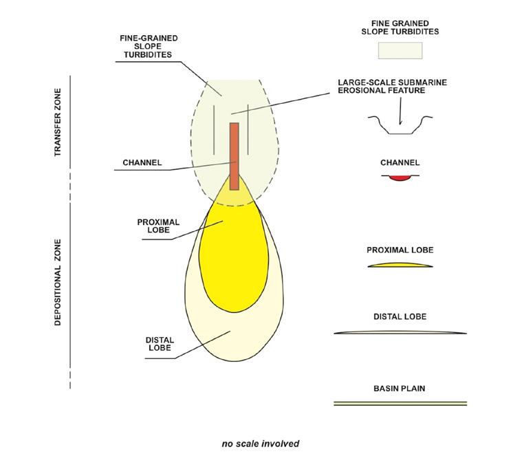
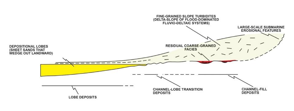
CHAPTER II: Turbidites TURBIDITE SYSTEMS: AN OUTCROP-BASED ANALYSIS 134
Fig. 96 - Conceptual planview model of a turbidite system (from Mutti et al., 1999).
Fig. 97 - Idealized dip section of a highly-efficiency turbidite system showing bypass channels, a channel-lobe transition zone, and basinal sandstone lobes pinching-out landward (slightly modified from Mutti et al., 1988).
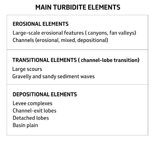
The main features observed in these sediments include:
• Mudstone-dominated facies with very thin siltstone/mudstone couplets thought to be the product of river plumes (Mutti et al., 2003). Occasionally, some siltstone beds have an upper rippled surface suggesting deposition from very dilute hyperpycnal flows (Figure 101).
Mudstone-dominated successions containing m-thick packets of roughly tabular or broadly lensing thin-bedded and fine-grained sandstones (Figure 102) which may be occasionally deformed by slumping. Lateral and vertical stratigraphic relationships suggest that these packets could be the slope extension of coeval shallow-marine flood-dominated sandstone lobes.
• M-thick chaotic units consisting of blocks of unconsolidated or weakly litified folded and disrupted
shelfal sediments floating in a sandy-muddy matrix with abundant shallow-marine skeletal debris.
Rotational slump units typically a few meters thick with very well-preserved extensional and frontal compressional features (Figure 103). These units are interpreted as the product of shallow downslope creeping.
• Large- to very large–scale slump scars. Some of these features may have widths of more than 10 km and depths of several hundreds of meters and are unconformably filled in with mudstone-dominated facies or by coarse-grained turbidites in their depest portions (Mutti et al., 1988). These large features are interpreted as sediment failures related to structural deformation on the seaward edge of prograding delta systems. Part of these features funneled subsequent sediment gravity flows, thus becoming turbidite conduits in their axial and deepest zones.
CHAPTER II: Turbidites TURBIDITE SYSTEMS: AN OUTCROP-BASED ANALYSIS 135
Fig. 98 - Main turbidite elements.
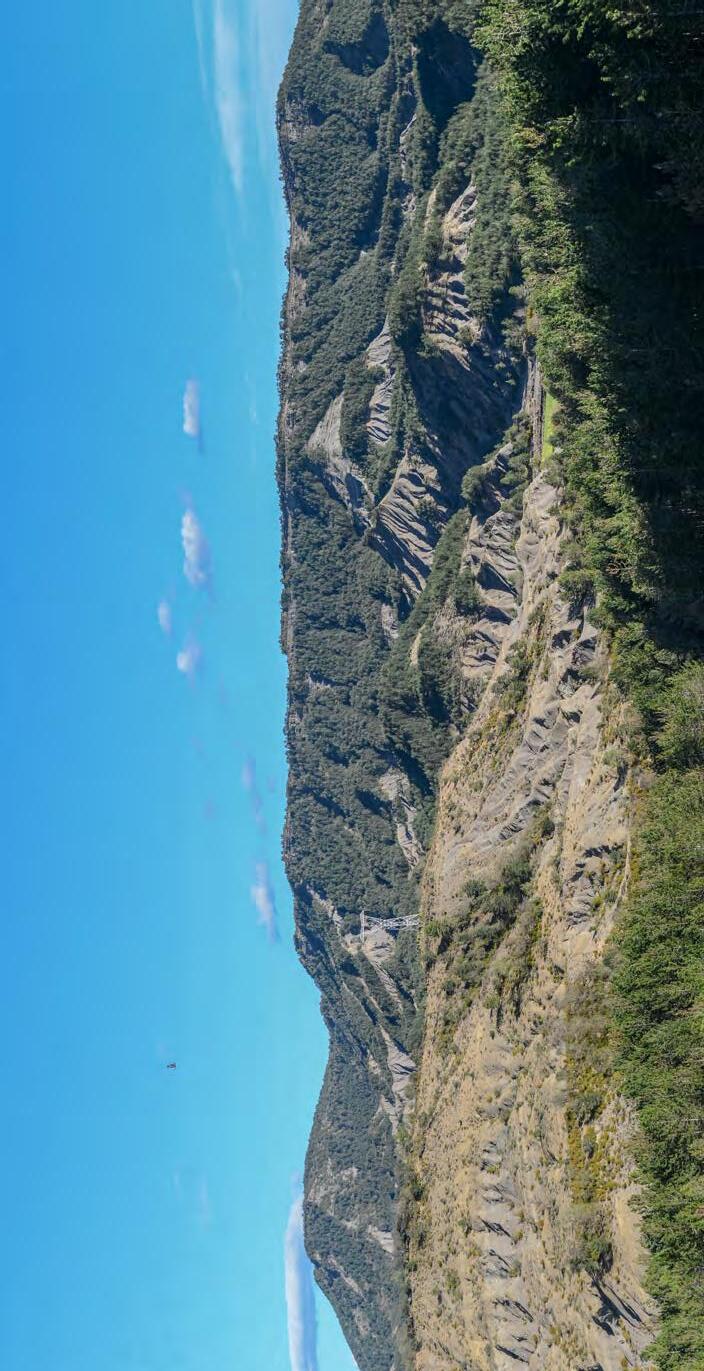
Fig. 99Spectacularly exposed mudstone-dominated slope sediments forming the delta-slope of a prograding delta-front succession. Eocene Castissent Group, south-central Pyrenees.
CHAPTER II: Turbidites TURBIDITE SYSTEMS: AN OUTCROP-BASED ANALYSIS 136
Delta-slope mudstones
Delta-front sandstones
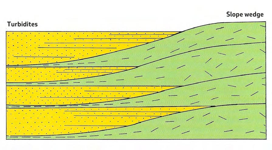
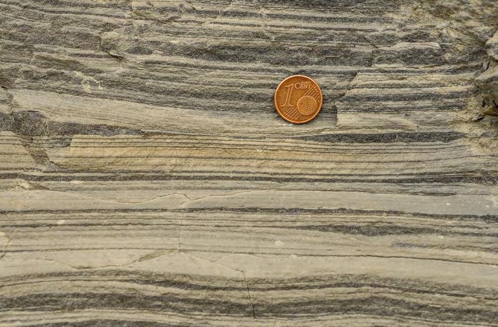
CHAPTER II: Turbidites TURBIDITE SYSTEMS: AN OUTCROP-BASED ANALYSIS 137
Fig. 100 - Stratigraphic relationship between slope wedges and basinal turbidites (basin-fill scale) (from Mutti et al., 1988).
Fig. 101 - Slope sediments. Thin siltstone/mudstone couplets thought to record river plumes. Some starved ripples are probably the deposit of dilute hyperpycnal flows. Eocene Castissent Group, south-central Pyrenees.
Slump unit
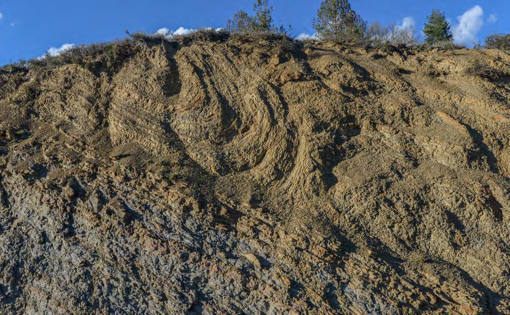
Thin-bedded slope turbidites
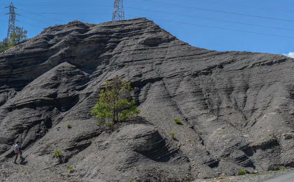
Rotational slump
CHAPTER II: Turbidites TURBIDITE SYSTEMS: AN OUTCROP-BASED ANALYSIS 138
Fig. 102 - Slope sediments. Packets of thin-bedded turbidites overlain by a slump unit. Eocene Castissent Group, south-central Pyrenees.
Fig. 103 - Slope sediment. Example of rotational slump. Sense of movement is from left to right. Eocene Castissent Group, south-central Pyrenees.
The example discussed above gives a quite clear picture of a tectonically unstable slope connecting a shelf to a basin and suggests that much work remains to be done on this kind of sedimentation, particularly as to their sequence stratigraphic significance. Part of these problems will be briefly discussed in the concluding chapter.
VI.4.3 – Turbidite elements
Large-scale erosional features are large canyons and fan-valleys, with widths up to several km and depths up to several hundreds of m, that are apparently restricted to similarly large fan systems developed in front of large and mature rivers. Basically, these features act as relatively long-lived sediment transfer zones or conduits of sediment gravity flows connecting clastic shelves to deep-water environments. Stated in more simple words, these features can be viewed as submarine rivers transfering sediment to deep-water deltas, i.e., submarine fans, over relatively long periods of time. Relatively stable tectonic settings and source areas are probably their fundamental controlling factors.
As shown by marine geology and high-resolution seismic studies, the fill of large-scale erosional features is very complex being controlled by alternating phases of erosion and bypass, deposition, and abandonment and by the local readjustment of the channel profile due to sedimentation or the growth of local synsedimentary structures. Knickpoint migration produced by growing structural features is one of the most important factors controlling depositional and erosional areas along the channel longitudinal profile (Heinio and Davis, 2007). Deptuck et al. (2003) have provided excellent examples of these very complex erosional features from the Indus Fan, Arabian Sea, and the Niger Delta slope (Figure 104).
These features may have lengths up to several hundreds of km and typically contain channels displaying complex planforms and cross-sectional geometry. Some of these channelized features and their levees, as in the case of the Congo deep-sea fan described by Picot et al. (2016) (Figure 94), extend for considerable distances basinward, apparently giving way to turbidite systems that substantially differ from the more common deep-sea fan models (see later). Here, in my opinion, long meandering channels act at the same time as transfer and depositional zones accumulating large amounts of sand in meandering belts much in the same way as meandering rivers do in subaerial alluvial plains. As a result, these systems have apparently little sand in terminal lobes.
These large-scale erosional features are basically absent in foreland basinfills for the simple reason that the large and mature rivers of passive margins are here replaced by much smaller, higher-gradient
and immature rivers developed in highly tectonically mobile settings. These features are thus omitted from the discussion in the following sections.
Channel-levee deposits form a very prominent and seismically well-defined element in some large recent and modern canyon-fed fans. Typically, these deposits are associated with fan valleys where thick turbidity currents previously contained within canyon walls expand and spill over channel crests forming thick accumulations of overbank fine-grained deposits dipping away from channel axes and wedging out and downlapping onto open-fan or interchannel regions. This kind of deposit has a very distinctive seismic signature in some modern and recent large mud-rich fans (Figure 105).
In small and sand-rich systems fed by similiarly small and high-gradient rivers, slope channels, and gullies, levee deposits may locally occur, as documented by Deptuck et al. (2008) for the small recent sandy fans off Corsica (see above). However, these deposits are difficult to recognize in most ancient successions since, if present, they are interfingering with virtually identical thin-bedded and fine-grained turbidites of the delta slope environment. Of course, the basic problem is whether a channel exists in association with these facies. Conversely, small packets of intra-channel overbank deposits produced by relatively small flows can be locally preserved and recognized in many channel-fill deposits. For the reasons above, also channel-levee complexes are also omitted in the following sections.
Channels and their fills are dealt with in number of papers (e.g., Clark and Pickering, 1996; Mayall and Stewart, 2000; Sprague et al., 2002; Posamentier and Walker, 2006; McHargue et al., 2011; Fildani et al. 2013; Covault et al., 2016; Pemberton et al., 2016) from both ancient and modern settings, covering most of the many problems related to this kind of turbidite sedimentation. These features are developed at a smaller scale than large-scale canyons and fan-valleys since they may occur within their fill, more basinward on open fan surfaces, as isolated features on slope regions, or as features connecting intra-slope minibasins in above-grade slope settings, thus covering a wide range of planform and cross-sectional geometries and possible origins.
Basically, a channel is a sediment pathway which is expressed by a negative relief and is partly filled in with sediment during its activity and partly upon its sudden or gradual abondonment. Most of channel characteristics are generally inferred from their geometry, sediment types, and vertical facies sequences. So, there may be some confusion between an empty feature (channel) and its fill (channel-fill). Channelized features vary greatly in scale, from that of a single channel element to that of much thicker and laterally extensive channel complexes (Figure 106).
CHAPTER II: Turbidites TURBIDITE SYSTEMS: AN OUTCROP-BASED ANALYSIS 139
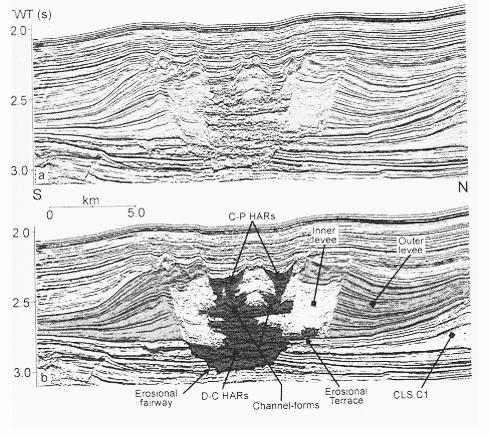
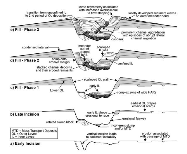
CHAPTER II: Turbidites TURBIDITE SYSTEMS: AN OUTCROP-BASED ANALYSIS 140
A B
Fig. 104 - A. Uninterpreted and interpreted seismic profile of the Indus channel-levee system showing erosional fairway, inner and outer levees, and high-amplitude reflections indicating channel deposits. B. Scheme showing the incision (a-b) and three-phase fill history of the Benin channel-levee system. From Deptuck et al. (2008).
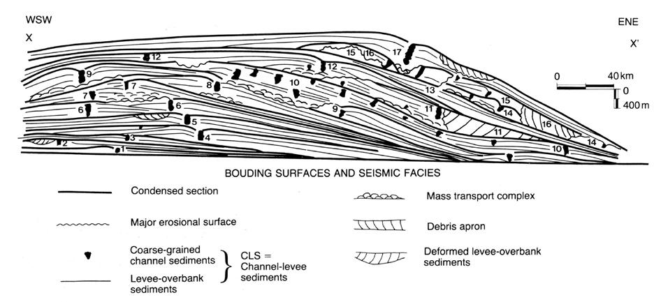
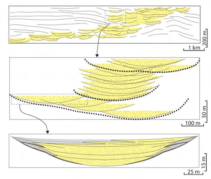
CHAPTER II: Turbidites TURBIDITE SYSTEMS: AN OUTCROP-BASED ANALYSIS 141
Fig. 105 - Cross-sectional geometry, stratal pattern, and main facies distribution of the youngest channel-levee deposits of the Mississippi Fan (from Weimer, 1991). Note the huge scale of the channel-levee complex.
Fig. 106 - Multiple scales of channelized features observed in turbidite systems (from Fildani et al., 2013).
By using a simple approach, Mutti and Normark (1987, 1991) have attempted to define erosional, mixed and depositional channels by comparing modern and ancient examples (Figure 107). Erosional channels show coarse-grained residual facies directly overlying the main basal erosional surface, thus indicating a phase of channel activity with sediment bypass. The abandonment stage is generally recorded by small, isolated and channelized sandstone bodies alternating with mudstones. An example of this kind of channel is shown in Figure 108 emphasizing the distinction between a first phase of channel activity and deposition of residual conglomerates and a second phase of abandonment. The two phases or stages are separated by a very clear surface. Depositional channels are expressed by thick, generally amalgamated sandstone beds in channel-axis zones that onlap onto and pinch out toward channel margins according to the scheme of Figure 109. Channel-margin facies are characteristically composed of thin rippled beds com-
monly without mudstone partings (Mutti, 1977). Typical examples of depositional channels are shown in Figure 110. Mixed channels include a bypass stage at the base followed upward by sand deposition similar to that of depositional channels. As noted by McHargue et al. (2011), mixed channels may show internal architectures and facies types suggesting underfilled and filled channel types (Figure 111). Both types are probably present also in depositional channels and represent but two examples of the many ways channels may be filled. Underfilled mixed channels are characterized by moderate to high rate of overbank aggradation and more abundant shaly partings in the axial facies; filled mixed channels would typically show low rate of overbank aggradation, which may be locally sandy, and common amalgamation of sandstone beds in the axial zone. Fining-upward facies trends recording channel abandonment are more common in underfilled settings. Some channel-fills may contain chaotic deposits at their base.
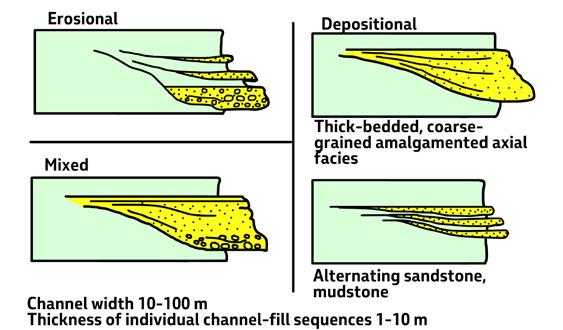
CHAPTER II: Turbidites TURBIDITE SYSTEMS: AN OUTCROP-BASED ANALYSIS 142
Fig. 107 - Basic types of channel-fill turbidites (from Mutti and Normark, 1987).
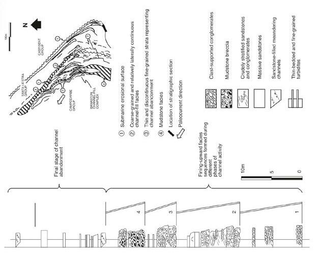
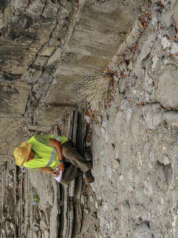
108Example of erosional channel showing a lower phase of activity (mostly residual clast-supported conglomerates) followed upward by a phase of abandonment (small sand bodies interbedded with mudstones). The abandonment surface is indicated by red arrow. The blue arrow indicates a small meandering channel formed on the channel floor during the abandonment phase. Eocene Gerbè-Cotefablo system, south-central Pyrenees (Figure on the left from Mutti et al., 1988).
CHAPTER II: Turbidites TURBIDITE SYSTEMS: AN OUTCROP-BASED ANALYSIS 143
Fig.
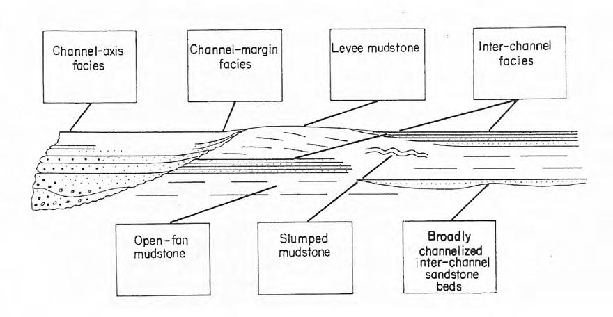
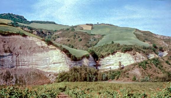
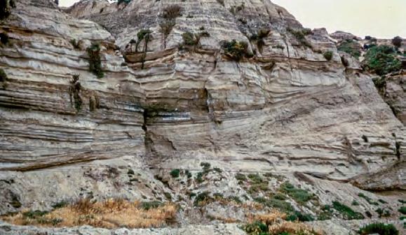
CHAPTER II: Turbidites TURBIDITE SYSTEMS: AN OUTCROP-BASED ANALYSIS 144
Fig. 109 - Idealized scheme showing a depositional channel and its relationships to levee and interchannel deposits (from Mutti, 1977).
A B
Fig. 110 - Examples of depositional channels: A. Miocene Marnoso-arenacea Formation, northern Apennines; B. Late Miocene-Pliocene Capistrano Formation, California (note thinning of sandstone beds toward channel margin).
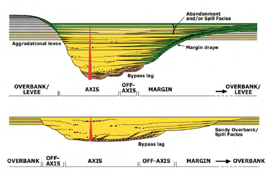
Sandstone-filled channels raise the problem of how sand deposition may occur within a conduit of turbidity currents, i.e., a sediment transfer zone. Deposition of turbidity curents may occur because of flow-stripping at sharp channel bends, the process through which a bipartite flow loses its upper more dilute portion (Piper and Normark, 1983), because structural and/ or depositional relief forces deceleration of turbidity currents and ensuing partial or complete deposition of their load, or more generally because flow volume de-
creases with time to the point that the lower segments of channels become depositional zones. This process, implying backstepping of the loci of deposition of turbidity currents from the lobe region to feeder channels is apparently the easiest explanation of lobe-type facies forming the fill of channels. The process, which has been suggested by Mutti and Normark (1987), is shown in Figure 112. Similar settings are described by Deptuck et al. (2008) from Quaternary fans on the eastern margin of Corsica (see above).
CHAPTER II: Turbidites TURBIDITE SYSTEMS: AN OUTCROP-BASED ANALYSIS 145
A B
Fig. 111 - Examples of underfilled (A) and filled (B) channels according to McHargue et al., 2011.
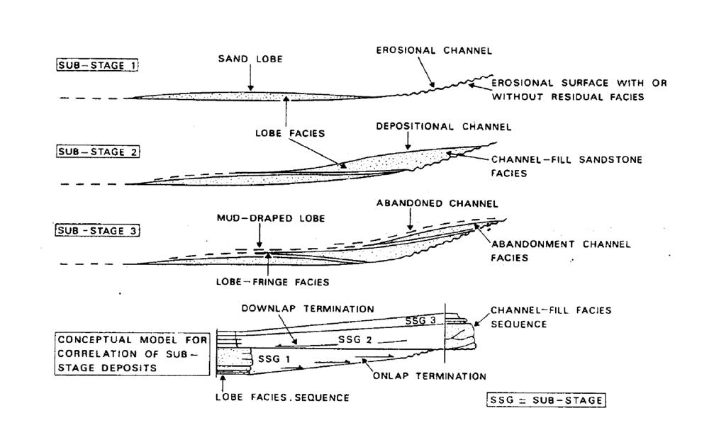
Channels, their origin and types of fills remain basically poorly understood despite the great number of papers available on the subject. Though very popular, large meandering channels appear restricted to specific settings of continental margins (see above). At a smaller scale and in tectonically mobile basin fills, meandering channels do occur, but are small and rare features commonly associated with the abandonment phase of major channelized units or, in some cases, with sandstone lobes (e.g., Van Vliet, 1982; Elliott, 2000).
113
are very important especially in identifying channel-lobe-transition zones, i.e., regions where strong turbulence generated by turbidity currents leads to localized bed erosion (see later). They are also important in defining facies types (see later). In Figure 113, A shows cut-and-fill features which are common at the base of or within structureless sandstone beds (Figure 114); B are tabular scours commonly found in sandstone lobes; and C are mud-draped scours indicating erosion followed by bypass (Figure 115). Large cut-and-fill scours can be easily mistaken for channels at outcrop scale.
CHAPTER II: Turbidites TURBIDITE SYSTEMS: AN OUTCROP-BASED ANALYSIS 146
Fig. 112 - Conceptual model showing backstepping of sand deposition from the lobe region to a channel due to decrease of flow volume with time: the lowermost diagram shows the correlation between lobes and channel-fill deposits (from Mutti and Normark, 1987).
Figure
shows the main types of scours that can be recognized at outcrop scale. These features
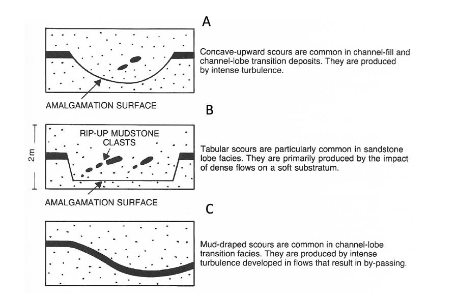
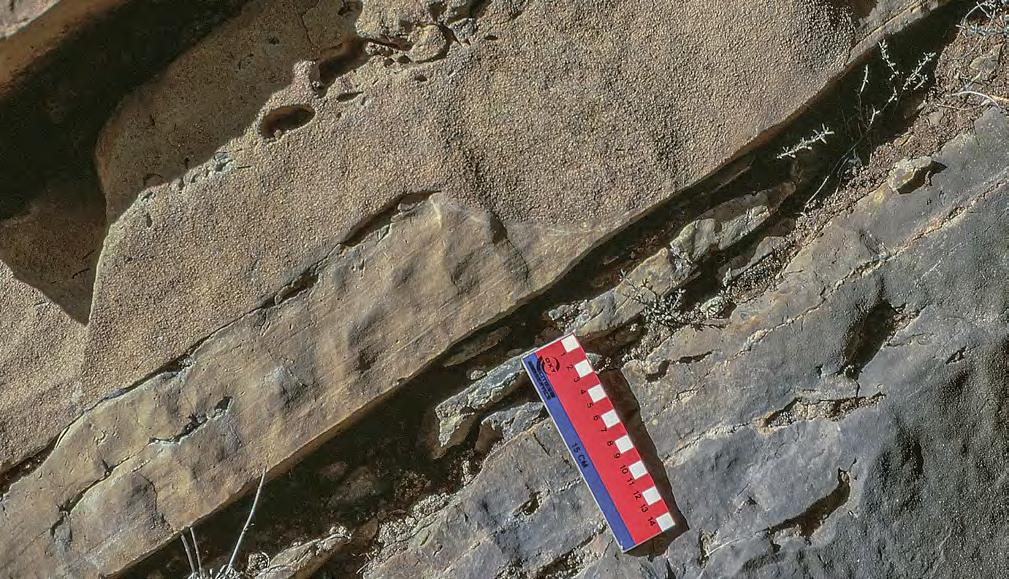
CHAPTER II: Turbidites TURBIDITE SYSTEMS: AN OUTCROP-BASED ANALYSIS 147
Fig. 114 - Small scour (cut-and-fill type) producing a concave-upward amalgamation surface (indicated by arrow) and mudstone clasts. Eocene Hecho Group, south-central Pyrenees.
A B C
Fig. 113 - Main types of scour which can be observed in turbidite sediments (from Mutti and Normark, 1987).
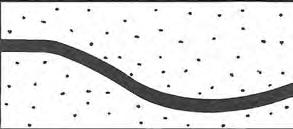
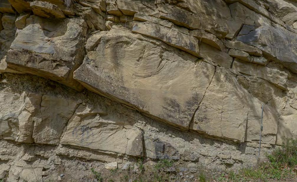
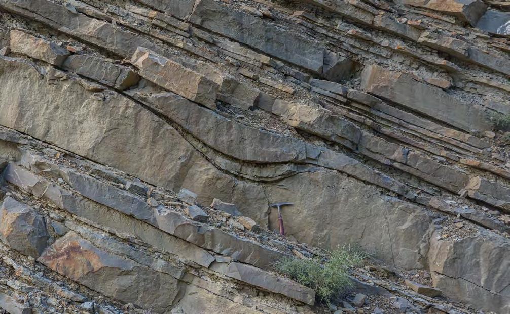
CHAPTER II: Turbidites TURBIDITE SYSTEMS: AN OUTCROP-BASED ANALYSIS 148
Fig. 115 - Mud-draped scours are produced by intense turbulence, bed erosion and bypassing. They are common in the channel-lobe transition zone. Eocene Hecho Group, south-central Pyrenees.
Mud-draped scour
Mud-draped scour
The channel-lobe transition element, as defined by Mutti an Normark (1987, 1991) is an important zone where turbidity currents undergo a dramatic transformation when passing from confined to unconfined conditions before spreading out basinward. The zone, abbreviated in CLTZ, is characterised by sudden deposition of thick sandstone beds forming the apexes of depositional sandstone lobes in poorly efficient systems. An association of erosional (scours, large flutes) and depositional (field of relatively coarse-grained bedforms) features, commonly below seismic resolution, are observed in highly efficient systems and interpreted as the product of bypassing large-volume flows carrying the bulk of their sediment load farther downsystem into the lobe region (Mutti, 1979; Mutti and Normark, 1987, 1991; Wynn et al., 2002, Tinterri and Tagliaferri, 2015). These features can only be recognized through careful facies analysis in outcrop or high-resolution marine geology techniques in modern settings. Among turbidite elements, the
CLTZ is the most difficult to map since its deposits interfinger with beds produced by turbidity currents of different volume and characteristics which were not affected by this kind of flow transformation. The sediments of this element are discussed in more detail in the following sections. Figure 115 A shows the basic differences between poorly efficient and highly efficiencient flows in the channel-lobe-transition zone.
The term lobe has been used in the literature in a somewhat loose sense and thus requires a definition. The “depositional lobe” of Normark (1970) refers to a morphological buldge developed in a mid-fan region and produced by deposition of sand at the exit of a leveed valley. The feature is most commonly referred to as suprafan (see above). The term “fanlobe” has been used by Bouma et al. (1985) to describe an entire stage of growth of a deep-sea fan encompassing all its erosional and depositional elements from a canyon to a basin plain.
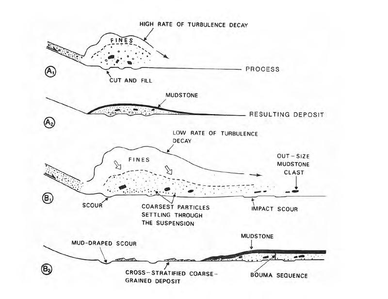
CHAPTER II: Turbidites TURBIDITE SYSTEMS: AN OUTCROP-BASED ANALYSIS 149
Fig. 115 A - Break in slope sedimentation of poorly-efficient (A) and highly-efficient (B) flows. A. small-volume, sand-rich flows depositing at the slope-break; B. large-volume, mud-rich flows bypassing the slope-break and depositing their sand load farther basinward (from Mutti and Normark, 1987).
Largely following Mutti and Ghibaudo (1972) and Mutti and Ricci Lucchi (1972), we use herein the term lobe element to define the main sandy depositional zone of turbidity currents within each considered system and, through the stacking of successive similar sand beds - a mappable element invariably present at the exit of feeder channels and thinning and shaling-out basinward, passing to basin-plain strata. The element in its most typical outcrop expression consists of uncannelized sandstone bodies, usually 3-15 m thick, made up of parallel-sided graded sandstone beds that can be amalgamated or more commonly separated by muddier divisions. These sediments can be considered as the most common and volumetrically important element of ancient turbidite systems of foreland basins , certainly the most classic expression of turbidite deposition and probably the most attractive reservoir for hydrocarbon accumulations . The concept of turbidity current of Kuenen and Migliorini (1950) actually stems from these parallel-sided graded sandstone beds in
the Oligocene and Miocene foredeeps of the northern Apennines. The Bouma sequence (Bouma, 1962) was also derived from the study of similar sediments in the Tertiary Peira Cava Formation (Annot Sandstone) of the Maritime Alps.
In small and short-lived systems, sandstone lobes may occur as isolated features enclosed by mudstone-dominated facies; in large and long-lived systems sandstone lobes may stack to form impressively thick successions of alternating m-thick sandstone bodies separated by variable, but usually thinner, muddier and thinner-bedded facies (Figure 116). The same variability can be observed in the lateral extent of lobe elements. In foredeep basins these sediments may form roughly tabular sandstone bodies that can be traced for tens of km, as documented in great detail by Remacha et al. (1998, 2003), Remacha and Maestro (2005), and Tinterri et al. (2003) in their work on the Eocene Hecho Group, south-central Pyrenees. An example is shown in Figure 117.
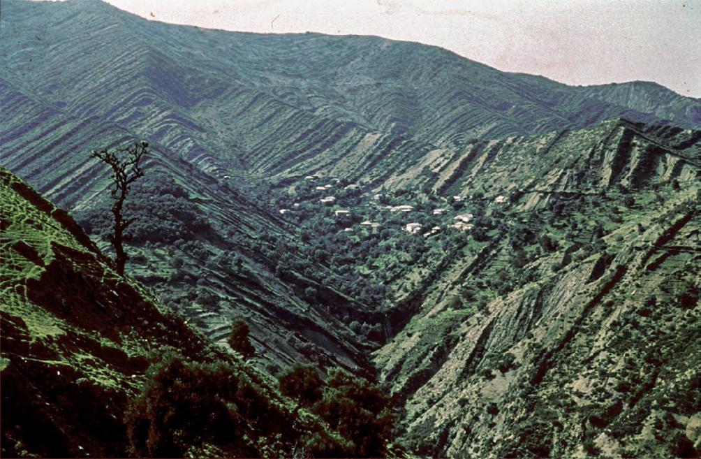
CHAPTER II: Turbidites TURBIDITE SYSTEMS: AN OUTCROP-BASED ANALYSIS 150
Fig. 116 - Impressively thick succession of turbidite sandstone lobes. Oligo-Miocene Zoumi Sandstone, Morocco.
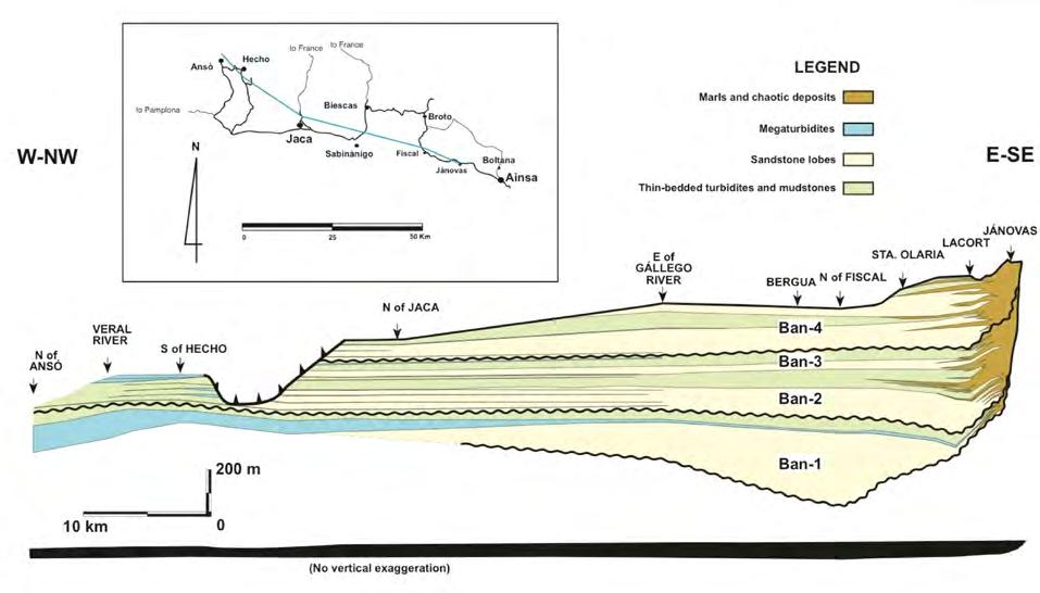
A lobate to elongate planview geometry is clearly documented by seismic and marine geology data for many modern and buried lobe elements (e.g., Piper and Normark, 1991; Deptuck et al., 2008). In large foredeeps, the planview geometry of sandstone lobes remains unclear. It is here suggested that this planview geometry should change from elongate to broadly lobate in a downsystem direction to account for the overall tabular geometry of these bodies in stratigraphic cross-sections.
In relatively small and sand-rich systems (poorly efficient systems) lobes apparently form near channel exits due to sudden breaks in slope and transition from confined to unconfined flow conditions. An excellent Quaternary example of this setting is that of the deep-sea fans described by Deptuck et al. (2008) from the eastern margin of Corsica (see above). More generally, it can be said that poorly efficient lobes consist of relatively thick sandstone bodies whose geometry and stacking patterns are strongly controlled by their depositional relief at the exit of channels. This relief generates processes of cannel avulsion, erosion and
compensation that considerably complicate the local architecture. Compensational features, as introduced by Mutti and Sonnino (1981), refer to flow deflections produced by previous depositional relief and ensuing formation of compensation cycles (Figure 118) that may considerably complicate an otherwise simple stacking pattern at different scales. Moving downsystem and laterally, lobes gradually thin-out and flow confinement diminishes resulting in sandstone bodies with more tabular geometry.
Proximal, high-relief sandstone lobes are associate with relatively thick compensation cycles (Figures 119 and 120). With distance the geometry of individual lobes tends to become more tabular in both poorly and highly efficient systems, compensation features still dominate at the scale of individual beds. Exposures are rarely large enough to permit their recognition in terms of lateral variations of individual beds (an exception is however shown in Figure 121 A), but their almost pervasive occurrence is documented by small-scale thickening-upward cycles within individual sandstone lobes (Figure 121 B).
CHAPTER II: Turbidites TURBIDITE SYSTEMS: AN OUTCROP-BASED ANALYSIS 151
Fig. 117 - Downsystem cross-section of the Eocene Banastòn system, Hecho Group, south-central Pyrenees. Note how lobe packages can be correlated over tens of km. Without vertical exaggeration (below) the system has an overall tabular geometry (from Mutti et al., 1999, originally from Remacha et al., 1998).
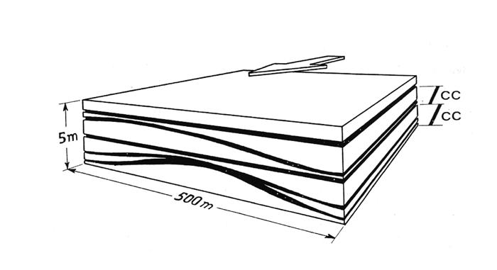
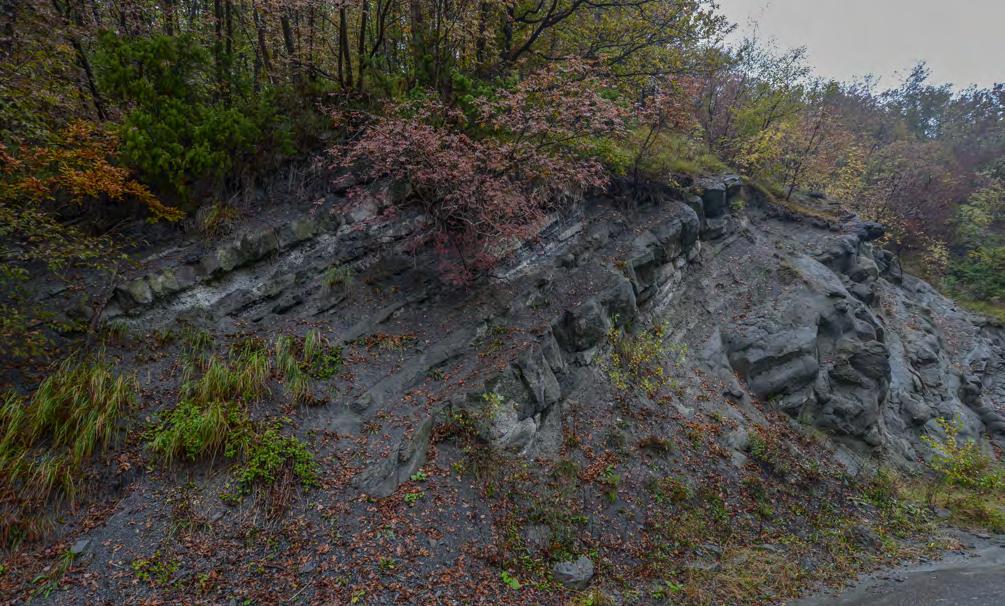
Compensation cycles
Thick-bedded lobe
II: Turbidites TURBIDITE SYSTEMS: AN OUTCROP-BASED ANALYSIS 152
CHAPTER
Fig. 118 - Compensation cycles (Mutti and Sonnino, 1981).
Fig. 119 - Thickening-upward compensation cycles above a thick-bedded, relief-forming sandstone lobe. Late Eocene-Oligocene Ranzano Sandstone, northern Apennines.
Thick-bedded sandstone lobe
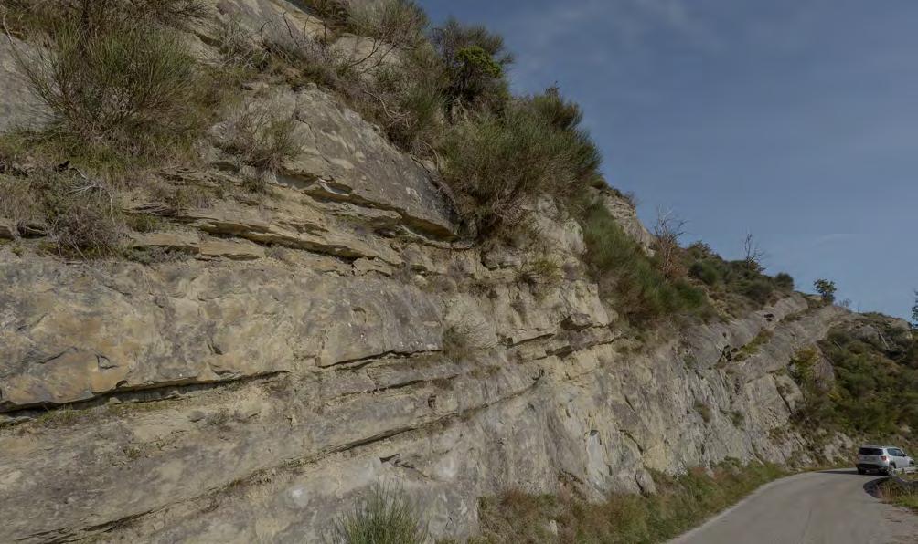
Following an early paper of Mutti and Ricci Lucchi (1974), individual turbidite sandstone lobes have been commonly thought in most literature as characterised by a thickening-upward trend of their sandstone beds and thus as prograding features similar to mouth-bar deposits of fluvio-dominated depositional systems. This was an oversimplification of a much more complex problem that raised many controversies resulting in different interpretations and re-definitions (see Pickering and Hiscott, 2016, for an extensive review). Basically, a correct understanding of lobe ciclicity and internal trends of individual lobes is fundamental for the recognition of a sandstone lobe, being clear that this is the typical case of interaction between autogenic processes, such as compensation and channel shifting, and allogenic processes, as related to elementary depositional sequences (EDSs, see chapter 1). The problem of cyclicity (see Figure 94 A) will be discussed in the final chapter of the book for both turbidite and fluvio-deltaic systems and necessarily considered within a high-resolution sequence stratigraphic framework). As suggested by Mutti (2011, AAPG invited lecture, Milan; 2013, Lamarck Medal Lecture, Vienna) autociclic processes in both types of systems seem to favour thinning- and fining-upward trends as a result of flow-volume decrease with time. Needless to say, the problem has a great relevance also for the interpretation of well logs. The example
of Figure 122 shows an outcrop example and its possible interpretation.
The basin-plain element (Mutti and Ricci Lucchi, 1972) records the distal depositional zone of turbidity currents, peripherally to the sandy lobe region and therefore characterized by finer-grained sedimentation (Figure 123). In common with the lobe element, basin-plain deposits are made up of parallel-sided beds which, in some ancient examples of confined basins, are conspicuous for their lateral continuity over distances up to several tens and probably hundreds of km (e.g., Ricci Lucchi and Valmori, 1980; Remacha et al., 2003; Amy and Talling, 2006; Magalhaes and Tinterri, 2010; Tinterri and Magalhaes, 2011, Sumner et al., 2012). Conversely, in small and sand-rich systems basin plain deposits can be only represented by thin, isolated packages of thin-bedded turbidites of limited areal extent (Figure 124). Particularly in ponded settings, like those of the Marnoso-arenacea and the Hecho Group, basin-plain deposits are characterised by the common occurrence of relatively thick sandstone beds with similiarly thick or, more commonly, thicker mudstone caps. Most of these beds have very complex internal divisions produced by ponding and reflection processes generated by bounding slopes (e.g., Remacha et al., 2005; Tinterri and Magalhaes, 2011).
CHAPTER II: Turbidites TURBIDITE SYSTEMS: AN OUTCROP-BASED ANALYSIS 153
Fig. 120 - Thickening-upward compensation cycles at the top of a thick-bedded sandstone lobe with scouring and amalgamation in its uppermost part. Miocene Laga Formation, northern Apennines.
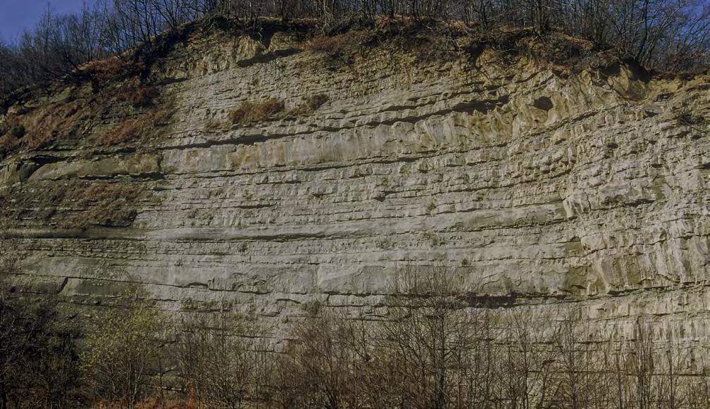
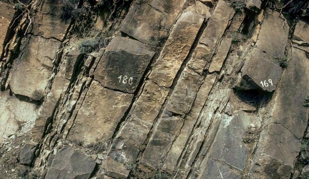
CHAPTER II: Turbidites TURBIDITE SYSTEMS: AN OUTCROP-BASED ANALYSIS 154
A B
Fig. 121 - Outcrop examples of compensation cycles at bed scale. A. Miocene Noceto Formation, Tertiary Piedmont Basin, NW Italy. B. Eocene Banaston system, south-central Pyrenees
Thinning direction of individual sandstone beds.
Thickening-upward compensation cycle.
Younger lobe compensating for previous relief
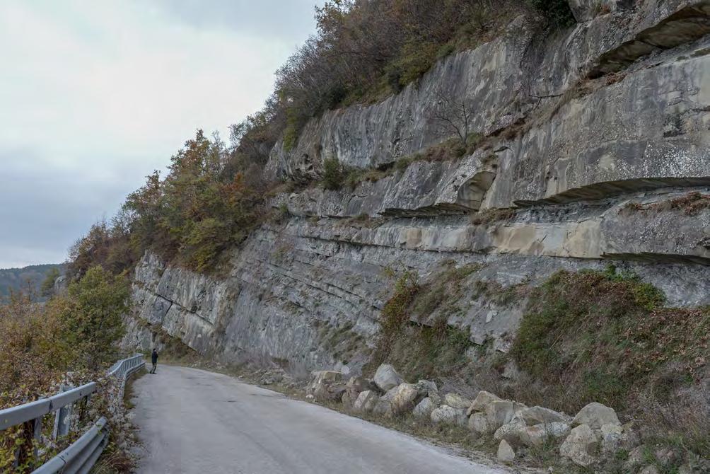
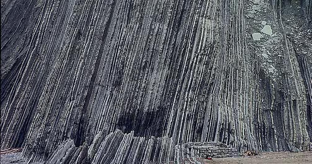
CHAPTER II: Turbidites TURBIDITE SYSTEMS: AN OUTCROP-BASED ANALYSIS 155
Fig. 122 - Sandstone lobes of the Miocene Laga Formation, northern Apennines. Available data do not permit to interpret this cyclic pattern in terms of autogenic or allogenic control.
Sandstone lobe
Lobe abandonment
Fig. 123 - Typical basin-plain deposits of a relatively large turbidite system. Note the regular bedding pattern of alternating mudstones, fine-grained sandstones and carbonates. Eocene Guipúzcoa Flysch, Basque country, Spain. See full outcrop at Figure 68.
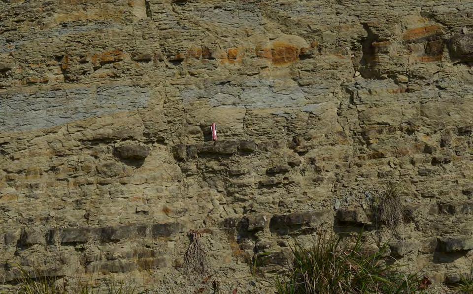
Because of their common tabular geometry, lobe and basin-plain strata can be lumped together, in some cases, as a more general sheet element of turbidite depositional systems which is well recognizable in ancient foreland basins and in modern abyssal plains (“sheet systems” of Pickering et al.,1989).
Albeit their general limited interest for hydrocarbon exploration, ponded basin-plain regions may represent the final depositional zone of giant sediment gravity flows whose run-out distance may reach 1500 m and have volumes well in excess of 100 km. Beds of this type tend to keep flat the basin floor smoothing out previous topography. Examples of this kind of extraordinary and catastrophic sedimentation are the well-known Missoula Flood and the Grand Banks turbidity current having their final depositional zones in the Escanaba trough in the Pacific Ocean, and the Sohm abyssal plain in the Atlantic Ocean, respectively (Figure 125). Similarly spectacular examples have
been described by Pilkey (1988) from the Hatteras Abyssal Plain, western north Atlantic, and Talling et al. (2007) from the offshore of northwest Africa. Ancient examples of this kind of catastrophic sedimentation are well known from the Eocene Hecho Group, south-central Pyrenees, where carbonate resedimented units, referred to as megaturbites, reach individual thickness up to 200 m, lateral extent up to 130 km, and have dry-sediment volumes in excess of 200 km (Johns et al., 1981; Labaume et al., 1987). At a smaller scale, a similar feature is that of the wellknown Contessa Bed of the Miocene Marnoso-arenacea (Ricci Lucchi and Valmori, 1980). Because of their very limited occurrence, these giant and catastrophic events are omitted in the following sections, though they could be excellent reservoirs if large volumes of sand would be involved in these flows. Because of their possible origin from earthquakes, sediments of this type were also referred to as seismoturbidites (Mutti et al., 1984).
CHAPTER II: Turbidites TURBIDITE SYSTEMS: AN OUTCROP-BASED ANALYSIS 156
Fig. 124 - Basin-plain expression of a very small and poorly-efficient turbidite system. Note very thin and laterally discontinuous sandstone beds with poorly developed internal structures. Tertiary Piedmont Basin, northern Italy.
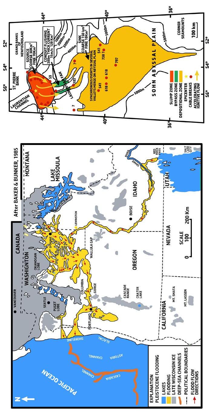
-
CHAPTER II: Turbidites TURBIDITE SYSTEMS: AN OUTCROP-BASED ANALYSIS 157
Fig. 125
Examples of giant flows: A. Missoula or Spokane flood; B. Grand Banks turbidity current of 1929 triggered by an earthquake.
VI.4.4 – A concluding remark
The association of erosional and depositional elements gives way to an almost endless spectrum of modern and ancient depositional systems greatly varying in both physical and temporal scales, planview geometry, and tectonic setting. At the two ends of the spectrum are km-scale and even smaller-scale systems occurring in slope mini-basins of divergent continental margins or in thrust-top basins of fold-thrust belts and modern
gigantic deep-sea fans mainly developed on oceanic crust. Basically, each system has to be described and interpreted on the basis of its own size, textural characteristics, elements, geometry and facies types. Despite these difficulties and whatever the physical and temporal scale involved, the simple diagram of Figure 126 may offer a preliminary appreciation of the main differences between channel, channel-lobe-transition, and lobe elements in terms of their most diagnostic features.
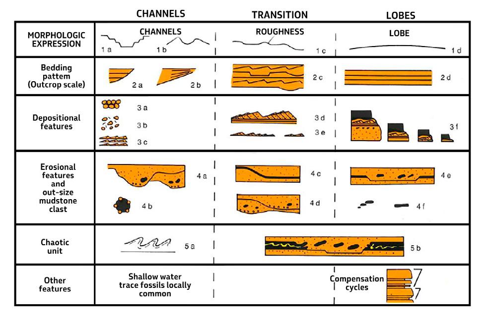
CHAPTER II: Turbidites TURBIDITE SYSTEMS: AN OUTCROP-BASED ANALYSIS 158
Fig. 126 - The diagnostic basic characteristics of channel, channel-lobe transition, and lobe elements (from Mutti and Normark, 1987).
VII – TURBIDITE FACIES
VII.1 - INTRODUCTION
Turbidite elements and their component sub-stages can only be described and interpreted on the basis of their facies and facies associations. At this point, an understanding of elements and sub-stages in terms of procesess and environments as well as of their possible sequence stratigraphic significance adds the “physiologic” information required to understand the dynamics of the systems and develop possible predictive criteria.
In recent times, research on turbidites has certainly moved, with very few exceptions, to process-sedimentology, with increasing interest in laboratory experiments, numerical modeling, theoretical considerations, and monitoring of modern flows in deep water. To support the above conclusion, the reader is referred to the paper of Talling et al. (2015), signed by 30 geoscientists from both academia and industry, indicating the “key future directions for research on turbidity currents and their deposits”. Certainly, rocks do not play a major role in these future directions.
I concur with Pickering and Hiscott (2016) that this phase of research has greatly contributed to a more robust hydrodynamic understanding of sediment gravity flows, or subaqueous sedimentary density flows. On the other hand, however, I believe that this phase of research has also shown the inherent complexity of these flows (see also Shanmugam, 2017) and – in my opinion – has led far away from simplicity and practical applicability to basin and facies analyis. This complexity, coupled with an increasing under-appreciation of rock characteristics – that is, the actual facies – has led to schemes (e.g., Mulder and Alexander, 2001; Postma and Cartigny, 2014) with little potential to facies analysis in the real world. Processes and terminology are discussed at length, but their product in terms of rock types is largely theoretical without a documented support from real examples.
The problems above clearly require a careful re-examination of many outcrops in order to develop some criteria to bridge the gap between the “classic” facies models
set forth in previous years and the many new data and ideas which permeate turbidite sedimentology today. This appears as a timely reminder of the need for revisiting turbidite facies in outcrop and cores with new eyes.
In the following sections, after a brief historical review of turbidite facies analysis, I will expand on the results of field studies I carried out in recent years revisiting a number of basin fills including, among others, the Tertiary Piedmont Basin, northwestern Italy, the Miocene Marnoso-arenacea and Laga formations, northern Apennines, and the Eocene Hecho Group and the Guipuzcoa Flysch in the south-central Pyrenees and the Basque region, respectively, Spain. The purpose of these studies was primarily a re-appreciation of many turbidite outcrops and facies also in the light of the many new contributions appeared in recent time to improve our understanding of turbidity currents and their deposits.
As a result, I came to the conclusion that a wise starting point could be that of working on an inventory of the many facies types comprising the spectrum of beds or divisions of beds that we can observe in a significant number of exposed ancient systems. The spectrum ranges from gigantic blocky-flow deposits to resedimented mudstone layers through an almost endless series of conglomerates, pebbly sandstones, structureless or internally stratified sandstones, and shale clast-rich sandstones and muddy sandstones. Each system has actually its own and probably unique characteristics dictated by the type of sediment available, initiation of turbidity currents and mass transport processes, flow volume and duration, bed erosion and ensuing flow bulking, basin size and configuration, and the local control exerted by both depositional and structural relief (see above). Nonetheless, an inventory of the main types of facies and an attempt to interpret them on the basis of our present knowledge appears as a necessary step to partly overcome the problems above.
The main objectives of the following sections are (1) to offer a general and descriptive subdivision of the main turbidite facies groups encompassing the full spectrum of deposits observed; (2) to present an inventory of the
CHAPTER II: Turbidites TURBIDITE SYSTEMS: AN OUTCROP-BASED ANALYSIS 159
main facies types (herein termed facies boxes) observed within each group with a tentative interpretation of their formative process or processes.
VII.2 - SELECTED PREVIOUS WORK
The first attempt to frame turbidity currents and their deposits within a more general scheme of “subaqueous gravity depositional processes” is certainly that of Dott (1963), who considered turbidity currents as the end member of a continuum from rockfall, slump and sliding, and mass flow, i.e., a continuum from elastic to fluid behavior of gravity-induced mass movements (Figure 127). A very important point highlighted by Dott (1963, p.113) is that “such theoretical distinction is real as attested by deposits in nature representing arrested examples of every gradation in the continuum”. As discussed in later sections, this concept forms the basis for interpreting turbidite facies tracts, from the paren-
tal-flow to distal quasi-static dilute suspensions.
The Bouma sequence (Bouma 1962), though originally intended to be mainly descriptive, contains in itself the assumption that a turbidity current is a non-uniform and unsteady flow, i.e., a flow decreasing its velocity and competence with distance and through time as shown implicitly by the Bouma’s cone (Figure 69). Following fundamental papers relating sedimentary structures and flow regime in flume experiments and modern alluvial channels (Simons et al., 1965; Harms and Fahnestock, 1965) and keeping in mind the “en masse” deposition of the “quick” liquefied bed described by Middleton (1967) in his experiments with high-density turbidity currents, attempts were to interpret the Bouma sequence in terms of upper and lower flow regime (e.g., Harms and Fahnestock, 1965; Walker, 1967; Pickering et al., 1989). These interpretations were summarized by Pickering et al. (1989) and are shown in Figure 128.
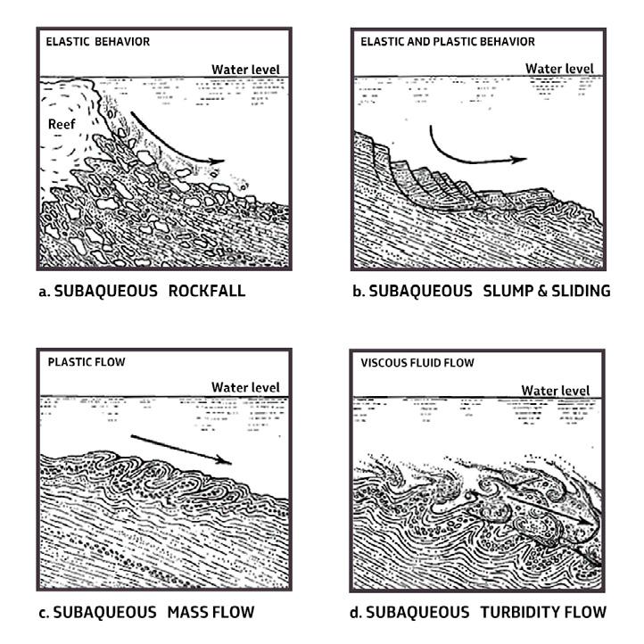
CHAPTER II: Turbidites TURBIDITE SYSTEMS: AN OUTCROP-BASED ANALYSIS 160
Fig. 127 - Major categories of subaqueous gravity movements (from Dott, 1963, AAPG Bulletin, v. 47, n. 1,pp. 104-128. Reprinted by permission of the AAPG whose permission is required for further use.)
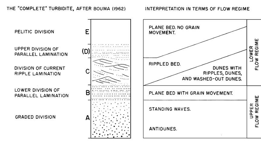
Beginning in the late 70’s and stemming from the papers by Mutti and Ricci Lucchi (1972, 1975), Walker and Mutti (1973), and Walker (1975, 1978) and the very influential paper of Middleton and Hampton (1973) on sediment gravity flows, a great number of authors started to investigate facies and inferred processes of turbidite beds and suggested their possible classifications which gradually became process-oriented.
Middleton and Hampton (1973) suggested that sediments generally referred to as the product of turbidity currents can be significantly subdivided according to the support mechanism maintaining the particles within the flow. The main types of mechanisms include turbulence (turbidity current s.s.), upward intergranular flow (fluidized sediment flow), grain interaction (grain flow), and matrix strenght (debris flow) (Figure 129). Though very important in many respects and notably because it introduced the concept of “sediment gravity flows”, this contribution fails to explain the great variety of facies that characterizes the vast majority of coarse-grained sandstone beds (see later) and defines univocally only the deposits of low-density or dilute turbidity currents and those of some debris flows. Surprisingly, Middleton and Hampton (1973) did
not consider the “flowing grain layer” of Sanders (1965) nor its relation to the complete Bouma sequence.
In two papers mostly based on theoretical considerations, Lowe (1976, 1979) expanded many of the concepts of Middleton and Hampton (1973) making a clear distinction between the fluid and plastic behavior of fluid flows (newtonian) and debris flows (non-newtonian) respectively, thus emphasizing the importance of fluid rheology. The types of flow and their nomenclature, as well as the sediment support mechanisms are shown in Figure 130.
Beginning with Walker (1965, 1978) and Mutti (1979), facies started to be interpreted in terms of their possible hydrodynamic significance and high- and low-density turbidity currents, along with debris flows, became the most likely processes to account for the vast majority of the turbidite facies observed in outcrop. In particular, Walker (1978) suggested a direct transition from turbulent debris flows to high-concentration (high-density) turbidity currents, thus eliminating grain flows and fluidized flows as a long-distance transport process (Figure 131). The same basic distinction between high-density and low-density turbidity currents forms the basis of the facies classification suggested by Mutti (1979) and shown in Figure 132.
CHAPTER II: Turbidites TURBIDITE SYSTEMS: AN OUTCROP-BASED ANALYSIS 161
Fig. 128 - Interpretation of the Bouma sequence in terms of flow regime (from Walker, 1967).
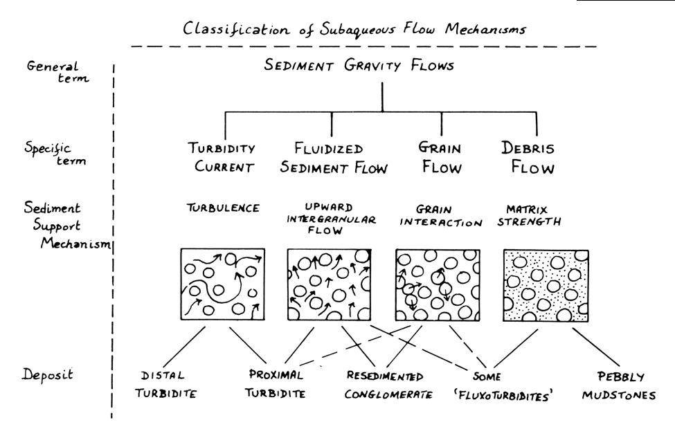
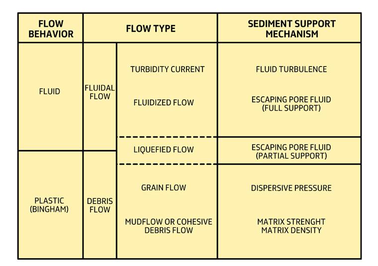
CHAPTER II: Turbidites TURBIDITE SYSTEMS: AN OUTCROP-BASED ANALYSIS 162
Fig. 129 - Sediment gravity flows and their sediment-support mechanisms (From Middleton and Hampton, 1973).
Fig. 130 - Main types of sediment gravity flows based on flow rheology and particle-support mechanisms (from Lowe, 1979).
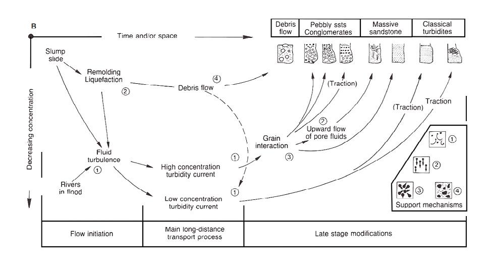
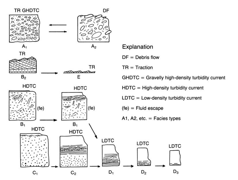
CHAPTER II: Turbidites TURBIDITE SYSTEMS: AN OUTCROP-BASED ANALYSIS 163
Fig. 131 - Facies and processes (from: Walker, R. G., 1978, AAPG Bulletin, v. 62, no. 6, p. 932-966. Reprinted by permission of the AAPG whose permission is required for further use.)
Fig. 132 - Facies scheme and related processes (from Mutti, 1979).
Lowe (1982) presented the first facies scheme with a thourough discussion on how turbidite beds can be related to a continuum of processes responsible of the deposition of both coarse-grained and finegrained internal divisions of these beds. The facies scheme of Lowe, emphasizing how different grainsize populations are controlling the type of internal divisions in turbidite beds, is summarized in Figure 133, which is also an attempt to reconcile the particle-support mechanisms of Middleton and Hampton (1973) with the real world of observable facies types. This scheme and the two classic facies sequences of Figure 134, intended to show the basic divisions of high-density and coarse-grained turbidite beds, have been and still are highly influential models for turbidite facies analysis.
A comprehensive facies scheme mainly based on outcrop studies was subsequently offered by Mutti (1992), who introduced the concept of facies tract as related to flow transformations of a parental flow occurring during its the downcurrent motion. The scheme is conceptually very simple in that is mainly based on the graphic presentation of a number of facies and related erosional features that record the arrested steps or deposits along an ideal depositional profile. These concepts, refined in subsequent work (Mutti et al., 1999, 2003; Tinterri et al., 2003), are amply discussed in the following sections.
Mulder and Alexander (2001) provide the most updated and comprehensive attempt to define the characteristics of sedimentary density flows (a new term apparently synonymous with the sediment gravity flows of Middleton and Hampton, 1973) and their inferred deposit. A first subdivision, based upon flow rheology, is between cohesive and frictional flows. Cohesive flows have matrix strength produced by cohesion between fine-grained particles; the strength maintains the coherence of the flow body. Conversely, frictional flows can develop intergranular space or porosity which is filled with water. Frictional flows are then subdivided based upon sediment concentration into hyperconcentrated density flows, density flows, and turbidity cur-
rents with different particle-support mechanisms. The scheme of Figure 135 summarizes flow and deposits characteristics. Though very useful for an understanding of processes, the scheme offers a very weak documentation of the characteristics of the resulting beds or facies, thus greatly limiting its applicability to the practice of facies analysis.
Talling et al. (2012) offer an extensive and critical review of the many attempts made by sedimentologists to classify turbidites, or more generally subaqueous density flow deposits. The authors also provide a new classification scheme based on deposits characteristics, dominant particle support mechanisms, and types of flow, with related new terminology (Figure 136). The authors are mostly concerned with sandy deposits, thought to be primarily deposited by high-density and low-density currents in a layer-by-layer aggradation fashion from an overlying suspension (Figure 137), and with associated shale clast-rich co-genetic debrites (see also Haughton et al., 2009; Sumner et al., 2012). Deposition of mudstone divisions is dealt with in great detail, but coarse-grained facies are virtually omitted from their discussion. If I correctly understood the authors’ opinion, structureless sandstone divisions would form from sandy cohesionless debris flows or from sustained liquefied zones at the base of high-density turbidity currents.
Pickering and Hiscott (2016) present a revised and well-illustrated version of their original facies classification (Pickering et al., 1989). The classification is primarily descriptive and covers a very wide spectrum of facies, hierarchically arranged in classes, groups, and facies. Albeit important as a reference, the classification, which also includes biogenic and chemical deposits, seems too complex to memorize and use in outcrop studies. Explicitly, Pickering and Hiscott (2016, p. 60) do not consider process-oriented facies schemes, such as that of Mulder and Alexander (2001), because they are not designed to be used in the field. My opinion is that such approach is conversely necessary since it does not deprive the geologist of the pleasure to try to understand what is observing.
CHAPTER II: Turbidites TURBIDITE SYSTEMS: AN OUTCROP-BASED ANALYSIS 164
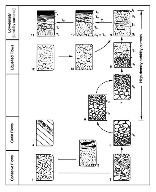
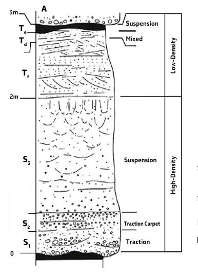
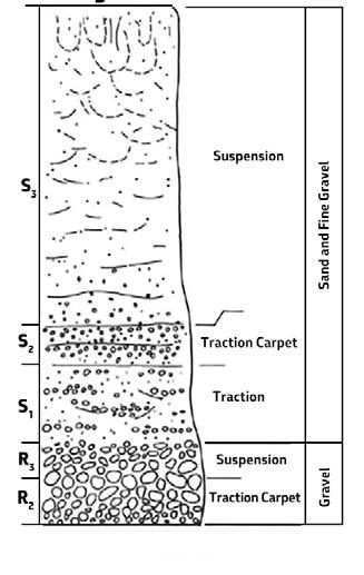
CHAPTER II: Turbidites TURBIDITE SYSTEMS: AN OUTCROP-BASED ANALYSIS 165
Fig. 133 - Facies and processes according to Lowe (1982) and the basic distinction between high- and low-density turbidity currents.
A B
Fig. 134 -A. Ideal deposit of a sandy high-density turbidity current showing both high-density (S1-3) and late-stage low-density (Tt, Tde) divisions. (From Lowe, 1982; reprinted by permission of Society of Economic paleontologists and Mineralogists). B. Ideal sequence of divisions deposited by a single, gravelly high-density turbidity current declining through gravelly and sandy sedimentation waves (from Lowe, 1982; reprinted by permission of Society of Economic Paleontologists and Mineralogists).
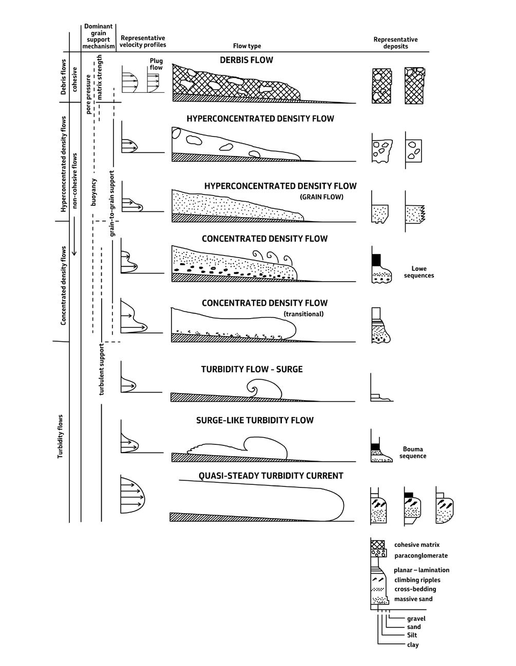
CHAPTER II: Turbidites TURBIDITE SYSTEMS: AN OUTCROP-BASED ANALYSIS 166
Fig. 135 - Sedimentary density flows and their deposits according to Mulder and Alexander (2001). See text for explanation.
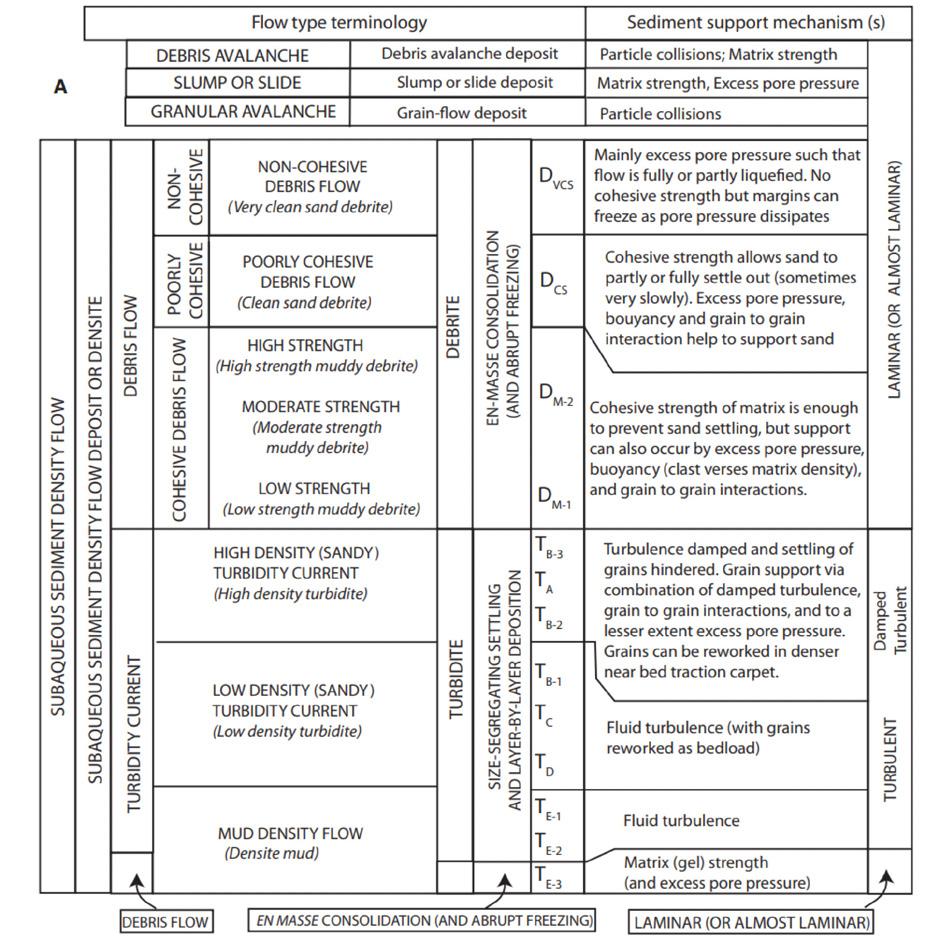
CHAPTER II: Turbidites TURBIDITE SYSTEMS: AN OUTCROP-BASED ANALYSIS 167
Fig. 136 - The basic distinction between debris flows and turbidity currents and their deposits according to Talling et al, (2012). Note that turbidity currents are further subdivided into mud density, sandy low density and sandy high density, and that debris flows are subdivided into cohesive, poorly cohesive and non-cohesive. Turbulence appears as the main sediment support mechanism in turbidity currents, whereas debris flows are considered as laminar or almost laminar flows with excess pore pressure and cohesive strength. See text for more details.
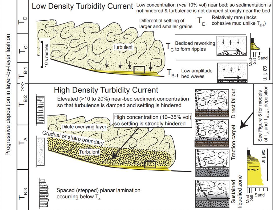
VII.3 - SOME REMARKS ON TURBIDITE FACIES ANALYSIS
It has become evident with time that turbidite facies analysis requires criteria that differ from those generally used for other types of sediments. Classic work of modern facies analysis primarily deals with packets of beds (essentially the bedsets of Campbell, 1967), their geometry, texture and internal structures, in an attempt to interpret sedimentary processes and ultimately the environment of deposition. The approach is well established in the literature and heavily relies upon a comparison between ancient facies and sediments, processes and environments observed in the Recent (see Chapter I). The same approach cannot be followed in turbidite facies analysis because sedimen-
tation takes place in deep-water and there are no direct observations linking turbidity current deposition to specific environments of deposition such as channels, lobes and basin plains. Turbidite facies analysis tends thus to restrict the interpretation to processes such as for instance high- and low-density turbidity currents, cohesive and frictional debris flows and hyperconcentrated flows overlooking the environment of deposition. Admittedly, most turbidite facies analysis is at present mainly based on inference of what happens in the deep sea, i.e., in environments far away from our direct control particularly over the very short lapse of time during which a turbidity current deposits its load (the reader is referred to an interesting discussion in Shanmugam, 2016).
CHAPTER II: Turbidites TURBIDITE SYSTEMS: AN OUTCROP-BASED ANALYSIS 168
Fig. 137 - Sediment transport and deposition in high-density and low-density turbidity currents according to Talling et al. (2012). Note that in the basal flow of high-density turbidity currents settling is hindered by elevated near-bed sediment concentration. In both low density and high-density currents deposition takes place in a layer-by-layer fashion from an overlying turbulent flow.
VII.4 - THE RATIONALE BEHIND NEW ATTEMPTS
Though still useful as a way of thinking, the general application of the Bouma sequence in turbidite facies analysis is now very limited because of the complexity of the problems encountered. In reality, turbidite facies form such a broad familiy of sediments that general classification schemes appear unrealistic at present. The problem has been summarized by Mutti (1992, p. 105) who claimed that, if viewed without preconceived ideas or existing models in mind, “no two turbidite beds are really the same”.
Difficulties emerge particularly when attempting to interpret the coarse-grained divisions of turbidite beds. The basic problem is to understand those dense flows that carry coarse-grained sediment (e.g., cohesive debris flows, hyperconcentrated and concentrated flows, high-density turbidity currents, sandy debris flows, grain flows, flowing or inertia grain layer). The ensuing tendency is to separate their deposits from those attributed to genuine turbidity currents in which finer-grained sediment is transported and deposited by turbulent suspensions. The term “turbidites” would be therefore restricted to the latter deposit, whereas most coarse-grained deposits would be described according to their inferred formative process. “Debrites” and “densites” are typical examples.
I think that it would be essentially useless to try to assign each bed forming a turbidite basin fill to a specific process. The final result would be a telephone book. And in addition, the interpretation of these processes would necessarily change with time thus rendering frustrating any attempt to stratigraphic and facies analysis. The problem was clearly perceived by Ph.H. Kuenen (in Sanders, 1965, p.217) who wrote: “A turbidity current is a current flowing in consequence of the load of sediment it is carrying and which gives it excess density. This leaves the controversial mode of suspension out of account (turbulence, impact, inertia flow, etc.” I fully agree with what Ph. H. Kuenen wrote more than 60 years ago.
Early in my career, I was in love with concepts and processes, but I was told by my manager at Exxon that the company was drilling rocks and not concepts and the same do geologists or geophysicists when mapping rock units in outcrop or in the subsurface. A lesson I learnt quite well. So, I have always been very pragmatic in this respect, which does not necessarily mean not being scientific.
To avoid terminology problems permeating most recent literature, turbidite facies are here intended as
originally defined by Mutti and Ricci Lucchi (1972), that is a spectrum of intergradational facies ranging from matrix-supported conglomerates to graded mudstones – the spectrum of lithologies that is commonly observed in orogenic belt turbidite basin fills. As a consequence, turbidity currents should be regarded not strictly as fully turbulent flows but as composite, most commonly bipartite flows (Mutti et al., 1999, 2003; see later), from which all these genetically inter-related facies can be deposited. Much remains to be learnt about the exact hydrodynamic behaviour of these flows and looking in detail at their products, though often difficult to understand, is certainly not a minor point.
VII.5 - DESCRIPTIVE AND GENETIC TURBIDITE FACIES
Descriptive facies are those based on objective lithologic criteria such as grain-size, sand:shale ratio, and bed thickness and geometry. The approach is useful for general description purposes in both outcrop and subsurface studies to preliminary define m- to damthick packages consisting of “roughly” similar beds. Figure 138 shows an example of descriptive facies from Mutti and Ricci Lucchi (1972).
Examples of descriptive facies terms are, for example, “thin-bedded turbidite sandstones”, “thick-bedded turbidite sandstones”, “massive sandstones”, “thick-bedded amalgamated sandstones”, “classic turbidites”, “graded pebbly-sandstones”, “channelized sandstones and conglomerates”, “clast- and matrix-supported conglomerates” and many other terms commonly used for purposes of general description. Using descriptive facies as operational stratigraphic and mappable units in both outcrop and subsurface studies is the most common approach in early attempts to understand the main stratigraphic and depositional framework of a basin fill.
Genetic facies are defined through a more detailed and time-consuming approach that considers individual beds or depositional divisions within each bed and describe them in terms of grain size and internal structures in the attempt to interpret depositional processes. The approach is therefore process-oriented and aiming at an understanding the way in which different facies form and grade into each other both laterally and vertically in order to develop predictive facies models. Most recent work on turbidite facies is essentially based on the genetic approach and largely relies on the facies tract concept (see below).
CHAPTER II: Turbidites TURBIDITE SYSTEMS: AN OUTCROP-BASED ANALYSIS 169
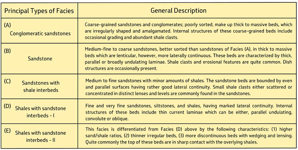
VII.6 - THE FACIES TRACT CONCEPT
Genetic facies can be best appreciated only within the framework of the facies tract concept. The concept has been introduced by Mutti (1992) in his classification of turbidite facies and implies a number of corollaries which are briefly discussed below.
A facies tract can be defined as the lateral association of genetic facies that can be observed within an individual bed or a package of strictly time-equivalent beds, or bedset (Mutti, 1992, p. 49). Both downcurrent and crosscurrent facies tracts can be observed, though downcurrent examples are most commonly considered (see later). A stratigraphic constrain is therefore essential to extract geologically significant conclusions from facies tract analysis.
The facies tract concept stems from field observations forcing the conclusion that sediment gravity flows undergo transformations during their downcurrent motion. Sediment gravity flows are non-uniform flows, i.e., flows that change their velocity with distance. As a rule, and after a phase of initial acceleration and bulking, these flows decelerate with distance thus depositing progressively finer grained sediment because of decreasing flow competency. Within a facies tract, each facies is thus always finer-grained than its upcurrent equivalent and coarser-grained than the downcurrent one. It follows that, as stated by Lowe (1982), in turbidite facies analysis grain
size, which is a function of flow competence, is of fundamental importance.
Each flow also changes velocity with time at each locality along the depositional profile. These flows are referred to as unsteady flows and produce variations in grain size and depositional structure within individual beds. As a rule, flows decelerate with time giving way to normally graded beds of which the Bouma sequence would be the ideal example. Turbidite facies tracts are thus the result of flow transformations in both space and time. Local variations in flow velocity mainly produced by sea floor morphology are omitted from this discussion.
The facies tract of Figure 139 A and its original interpretation (Figures 139 B and 140) show the downcurrent evolution from matrix-supported conglomerates to graded turbidite mudstones and discuss flow transformations from dense debris flows to dilute quasi-static turbidity currents in the same direction. The scheme of Figure 139 A restricts turbidite facies to 9 main types (F1 to F9) thought to represent the basic and most common (in this writer’s experience until 1992) depositional divisions observed in outcrop studies mainly from foreland basin fills of the south-central Pyrenees and northern Apennines, as well as from wedge-top small systems of the Tertiary Piedmont Basin, north-western Italy.
CHAPTER II: Turbidites TURBIDITE SYSTEMS: AN OUTCROP-BASED ANALYSIS 170
Fig. 138 - Example of descriptive turbidite facies (based on Mutti and Ricci Lucchi, 1972).
A refined version of the above schemes has been offered by Mutti et al. (1999, 2003) and Tinterri et al. (2003) who introduced the concept of bipartite turbidity currents and their basic subdivision into a basal dense flow and a more dilute upper turbulent flow – a concept originally suggested by Sanders (1965), admitted by Middleton and Hampton (1973) and strenghtened by Ravenne and Beguin (1983) and Norem et al. (1990) on the basis of laboratory experiments and numerical modeling respectively. In particular, Norem et al. (1990) emphasized the importance of the excess pore pressure of dense or granular flows which would reduce internal friction, thus allowing them to run over considerable distance. The basic scheme of Mutti et al. (1999, 2003) is shown in Figure 141, portraying a bipartite turbidity current
with a dense basal flow moving ahead of and faster than an overlying turbulent flow. With distance, the dense flow loses its excess pore pressure, freezes and is bypassed and reworked by the turbulent flow that moves farther downcurrent. The above authors also attempted to simplify facies types and inferred transport and depositional processes in terms of grain-size populations, their downcurrent segregation and associated erosional, depositional and bypass features (Figure 142).
Flow transformations may occur without leaving a distinctive depositional record and some of them can only be expressed by erosional features (mud-draped scours in the sense of Mutti and Normark, 1987,1991). Also, these erosional features have thus to be taken into account for the interpretation of facies tracts.
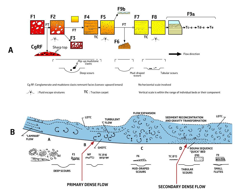
CHAPTER II: Turbidites TURBIDITE SYSTEMS: AN OUTCROP-BASED ANALYSIS 171
A B
Fig. 139 - (A) Facies tract and inferred depositional processes (slightly modified from Mutti, 1992). Note the inferred main transformations of the flow (B) and the occurrence of a primary and secondary dense flow. The latter would form from reconcentration of the flow after its expansion at a hydraulic jump (flow expansion in the figure) and would be responsible for the genuine graded and structureless division of the Bouma sequence.
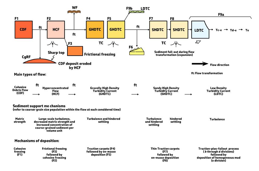
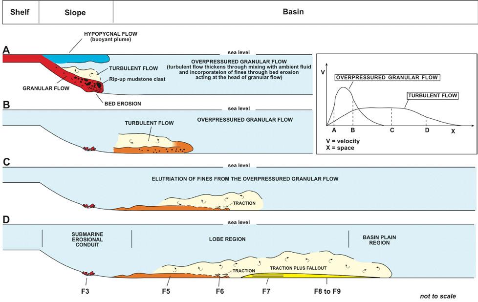
CHAPTER II: Turbidites TURBIDITE SYSTEMS: AN OUTCROP-BASED ANALYSIS 172
Fig. 140 - The facies tract of Mutti (1992) showing types of flow, particle–support mechanisms, depositional processes, and suggested terminology.
Fig. 141 - The scheme of a bipartite turbidity current with its basic depositional zones (from Mutti et al., 1999).
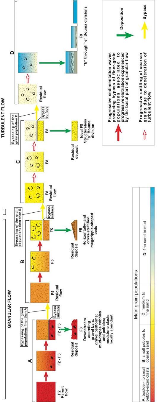
Note the fundamental role played by grain-size populations.
142Transport, bypass, and deposition of an ideal bipartite and highly-efficient turbidity
CHAPTER II: Turbidites TURBIDITE SYSTEMS: AN OUTCROP-BASED ANALYSIS 173
Fig.
The above schemes refer to an original parental flow containing all the grain size populations and its progressive transformation from a blocky or gravelly flow into a dense sandy flow. These flows (termed granular flows in Figures 141 and 142) can be simply referred to as dense flows, i.e., flows with high sediment concentration that are generally known as debris flows, hyperconcentrated flows, gravelly flows, sandy debris flows, high-density turbidity currents and other similar terms (see above). Following the schemes of Mulder and Alexander (2001), frictional dense flows as intended herein should encompass a range of flows with decreasing sediment concentration from hyperconcentrated flows (up to more than 25 % by volume), with no vertical particle sorting, to concentrated density flows, with coarse-tail vertical grading allowed by limited vertical settling. For further decrease in sediment concentration (< 9% by volume), concentrated density flows would then become turbulent flows, i.e., true turbidity currents. As discussed later, facies analysis makes this problem considerably more complex.
The schemes of Figures 141 and 142 depict facies tracts characteristic of very efficient flows. Provided the flow can travel over sufficient distance, the process produces a clear grain-size segregation in a downcurrent direction expressed by very distinctive facies indicating successive phases of deposition and bypass until even the finest sediment load is deposited in distal regions during the final waning stages of the current. Such flows have been referred to as highly efficient; conversely, very poorly efficient flows will only partly segregate their different grain size populations, thus producing a more limited number of facies types with poor textural sorting (Mutti, 1979, 1992; Mutti and Normark, 1987, 1991; Mutti et al., 1999). The scheme of Figure 143 illustrates the concept of flow efficiency and its depositional characteristics.
Figure 139 shows facies the way you can see them in outcrop or in cores when you attempt to organize your observations within a logical and predictive framework. A facies is essentially defined on the basis of the texture and internal depositional structures within individual beds or packets of beds, or bedets. More specifically, a facies can be defined as the dominant and coarser-grained division within a bed. The scheme is based on the fundamental stratigraphic principle, the Walther principle, that states that a facies has to be considered also in terms of lateral and vertical stratigraphic relationships. Therefore, in the specific case of turbidites, a facies is but a piece of a broader spectrum of related facies that record deposition from a single flow event through transformations suffered during its basin-
ward motion. In the scheme of Figure 72, each facies is simply coarser grained than the facies upcurrent and finer grained than the downcurrent one in the reasonable assumption that overall a flow is not uniform and decelerates with distance, thus loosing competence. Textural characteristics are supplemented with internal structures and other features thought to be important.
If flow characteristics are taken into account, then a turbidity current can be splitted into a spectrum of flow types ranging from a hyperconcentrated frictional flow to a dilute turbulent suspension, all the spectrum members being part of the same turbidity current, that is the same episodic event. A correct description an understanding of these facies has enormous implications for reservoir geology.
To sum up and largely following the previous schemes of Mutti (1992) and Mutti et al. (1999, 2003) assuming that the grain-size populations transported by each flow are deposited in a predictable order of depositional divisions both vertically and longitudinally, an ideal turbidity current gives way to depositional cone that thins and fines outward. The cone can be considered as an elementary depositional lobe built up by a single flow.
The scheme omits the problem of the interaction between flow motion and submarine relief generated by structural deformation or previous deposition. These settings can only be understood on a case-by-case basis and also include flow waxing, waning and even local current reversal associated with the formation of specific supercritical bedforms (e.g., chutes and pools and cyclic steps). Most commonly, the flow naturally decelerates with distance and through time because of deposition (loss of density), friction and subtle slope decrease in an essentially smooth basinal region. The mixture of sediment and water that moves because of its excess density, and which we consider as a bipartite turbidity current, undergoes flow transformations that result in a continuous process of deposition of the relatively coarser grain-size populations and bypass of the finer ones until the final settling of a muddy cloud (Figure 142). The resulting bed and its internal divisions record the facies tract of the considered flow (Figure 139 A). As noted above, the deposit of a single composite sediment gravity flow, whatever the mechanisms and the resulting facies, is considered as a “turbidite bed” produced by the same event and its transformations in space and time. Strictly speaking, a turbidite bed becomes in this way an intra-bed facies association or facies tract.
CHAPTER II: Turbidites TURBIDITE SYSTEMS: AN OUTCROP-BASED ANALYSIS 174
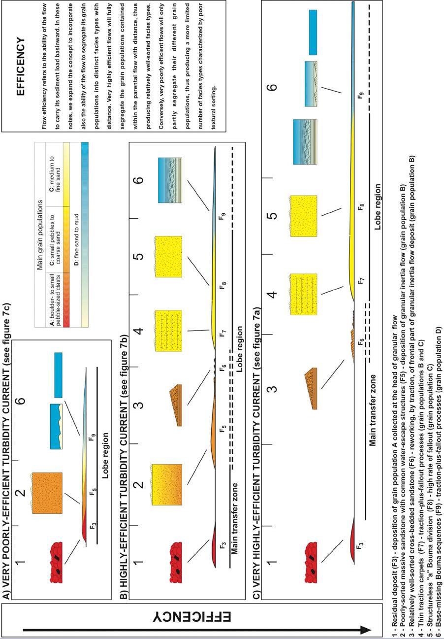
Fig. 143Poorlyand highly-efficient turbidity currents as envisaged by Mutti et al. (1999) (see also Mutti, 1979).
CHAPTER II: Turbidites TURBIDITE SYSTEMS: AN OUTCROP-BASED ANALYSIS 175
VII.7 - THE CHANNEL-LOBE TRANSITION ZONE AND ITS PROBLEMS
An early and tentative interpretation (Figure 79) assumed that in highly efficient flows a basic transformation occurs at a change in slope or at the exit of a channel from a supercritical dense flow to a subcritical and fully turbulent flow, i.e., the flow suffers a hydraulic jump implying flow expansion and deceleration. This zone has been referred to as “channel-lobe transition (CLTZ)” by Mutti and Normark (1987, 1991) and Winn et al. (2002) and thought to be critical for the downcurrent evolution of turbidity currents (see above). Its characteristics were defined to include scours, mud-draped scours, and fields of sediment waves produced by tractional processes (primarily cross-laminated sandstone beds formed by migrating dunes). These features were summarized in the scheme of Figure 126, showing the basic differences between channel, channel-lobe transition zone, and lobe elements. Following and expanding on the original scheme of Mutti (1979), all these features were interpreted as the result of hydraulic jumps of supercritical flows followed by sediment bypass and deposition of the main sand load in lobe regions farther downsystem. As noted by Mutti and Normark (1987, p. 24), the hydraulic jump zone was not related to a substantial reduction in the capacity of the flows to carry sand farther basinward in the lobe region, a concept recently expanded and substantiated by Dorrell et al. (2016).
The problems of the hydraulic jump, its location and impact on the flow have recently become matter of debate and are far less simple than previously thought. Direct monitoring of submarine density flows, numerical modeling, small-scale laboratory experiments, some limited field evidence and theoretical considerations (e.g., Kostic and Parker, 2006; Postma et al., 2009; Sumner et al., 2013, with references therein; Dorrell et al., 2016;) show the complexity of the problem which is still in its infancy (see a critical review by Shanmugam, 2016). Yet, and for our purposes, all the available information indicates that this basic transfomation does exist, though it may be expressed in different types of record, some of which still remain unclear or unrecognized. Nonetheless, there seems to be a general consensus that hydraulic jumps are associated with scouring of the sea floor and sediment waves of various size
and sediment type that may extend basinward from channel exits over considerable distance.
VII.8 - A SUGGESTED NEW CLASSIFICATION
VII.8.1 - Introduction and basic subdivisions
Being aware of the many problems discussed in previous sections and based on new field observations (see above), an attempt is made here to try to reconcile part of the new data emerged about turbidity currents and their deposits with classic facies schemes. The resulting new scheme is shown in Figure 144.
We identify 6 main facies groups (termed F1 through F6) that allow for the subdivision of turbidite successions into packages or for the identification of beds that are easily recognizable on their objective characteristics and primarily on their texture. Other criteria include bed thickness and geometry, sand/shale ratio, and internal structures. These facies groups are conceptually similar, though considearbly refined, to the main descriptive subdivisions introduced in early work by Mutti and Ricci Lucchi (1972), Walker and Mutti (1973), and Walker (1965) and are thought to represent the first step to be taken in turbidite facies analysis when examining outcrops or cores.
The groups include include (Figure 144):
F1 - Conglomerates (both matrix- and clast-supported) and pebbly sandstones;
F2 - Structureless sandstones commonly including granules and small pebbles;
F3 - Internally-stratified, well- to relatively well-sorted coarse- to fine-grained sandstones;
F4 - Dune- and ripple-shaped medium- to very coarsegrained sandstones; dune-shaped beds commonly show internal cross laminae;
F5 - Shale-clast bearing sandstones and muddy sandstones;
F6 - Thoroughly current-laminated, fine- to very-fine sandstones and coarse siltstones commonly grading upward into mudstone divisions and occasionally underlain by a fine-grained structureless divisions (Bouma-like beds).
CHAPTER II: Turbidites TURBIDITE SYSTEMS: AN OUTCROP-BASED ANALYSIS 176
F6
Graded and parallel-sided beds of highly variable thickness of fine to very fine sandstone transitionally capped by a mudstone division. Typical internal structures from turbulent flows produced by traction-plus-fallout processes which may be locally strongly affected by depositional and structural relief. Bouma-like beds.
F5 Sandstone beds with floating shale clasts and/or containing divisions of muddy sandstone locally with pseudonodules and small shale clasts.
F4 Dune- and ripple-shaped cross-laminated beds of relatively well-sorted coarse- to medium-grained sandstone.
F3
F2
Medium to thick beds of laminated coarse to fine sandstone.Thick to thin horizontal, wavy, and low-angle cross laminae. Fairly to very well sorted. Large- to small-scale water escape features.
Medium to very thick beds of structureless and poorly-sorted coarse- to fine sandstone, locally with small pebbles and granules. Beds vary from well to crudely graded. Many beds show multiple grading produced by scours associated with traction carpets.
F1 Matrix-supported and clast-supported conglomerates / Graded pebbly sandstones. Tectonic melanges, large-scale mass-transport deposits (slumps, slides, blocky flows).
Though the groups are primarily descriptive, some interpretation becomes implicit in the way they are ordered in Figure 144. From base to top, F1 and F2 are simply defined by their grain-size populations. F3 is defined by grain-size and internal stratification. F4 is defined primarily by bedding geometry, grain size and internal structures. F5 is defined by beds containing shale clast-rich divisions as well as muddy-sandstone or sandy-mudstone divisions with small shale clasts and pseudonodules of rippled sandstone. Finally, F6 contains beds that can be described according to the sequence of depositional divisions of the classic model of Bouma (1962), though with common and substantial departures.
The scheme shows the evolution from gravelly (F1) and sandy (F2) dense flows to turbulent flows (F3). Beds of F2 and F3 are seen in most cases to be locally overlain by F3 deposits interpreted as tractional and aggradational features following settling from a suspension. F6 deposits are finer-grained traction-plus-fallout deposits from an overlying turbulent suspension (see later for F5). The scheme thus shows an overall tendency in the evolution of facies groups as well as of individual beds toward a decrease of dense-flow sedimentation which is gradually replaced by that of more dilute flows where turbulence becomes increasingly important. The process leads also to a general decrease in grain size and increase in textural sorting.
The scheme is largely based on the interpretation of F4 deposits. Dune-shaped and relatively coarse-grained sandstone beds (facies B2 of Mutti, 1979; facies E of Mutti and Normark, 1987; facies F6 of Mutti, 1992). These beds, which are common though unfortunately overlooked, are here interpreted as a genuine expression of sand dune migration under subcritical flow conditions. Their cross laminae are invariably indicating paleocurrent directions parallel to flute casts and their relative stratigraphic position shows without any possible doubt that these cross-stratified sandstones directly overly current-laminated deposits of F3. The same kind of dune-shaped and cross-laminated sandstones is also commonly found at the top of structurelss bed of F2 (e.g., Mutti, 1992; Tinterri and Tagliaferri, 2015; Cunha et al., 2017).
F4 beds are thus of fundamental importance since they record the first and clear evidence of a subcritical flow regime, thus marking a significant boundary between types of flow and resulting deposit. Note that a similar conclusion was reached by Hiscott and Middleton (1979) in their study of the lower Ordovician Tourelle Formation, Quebec, Canada, where cross-bedded divisions overlay structureless divisions thought to be the deposit of supercritical flows.
As schematically shown in Figure 145, F1 through F3 are thus interpreted here as the deposit of fast-moving dense (F1 and F2) and turbulent (F3) supercritical flows (Fr >1) whilst the groups above are interpreted as the
CHAPTER II: Turbidites TURBIDITE SYSTEMS: AN OUTCROP-BASED ANALYSIS 177
Fig. 144 - Basic turbidite facies groups. See text for details.
deposit of subcritical flows (Fr <1) (though with some exception for F5 beds; see later). The transition between the two types of flow is recorded by a still poorly understood region where supercritical flows suffer hydraulic jumps marked by flow thickening and deceleration with dissipation of energy through intense turbulence (channel-lobe transition zone, see above). These features are thus closely associated with scours and mud-draped scours. As noted by Mutti and Normark (1987, p. 24), the hydraulic jump zone is not related to a substantial reduction in the capacity of the flows to carry sand farther basinward in the lobe region.
Within each group we further identify a number of selected facies, simply indicated by progressive numbers (e.g., F1–1, F1-2 etc), on the basis of textural characteristics and internal depositional structures. We define herein these facies as facies boxes and show part of them graphically to emphasize their main characteristics which allow for a preliminary interpretation of their formative process or processes. It should be noted that the selected facies boxes represent but a fraction of the variants you can observe in the field as perceived by Dott (1963) (see above). The selection offered here is obviously based on my own experience and reflects my personal conviction that these facies boxes are especially common and significant in the systems I could examine. Unlike in previous work (e.g., Mutti, 1992), facies boxes are not arranged in a new classification scheme, but are rather intended as a subjective guide-
line for examining outcrops and cores and to share my way of thinking with the reader. Facies groups and their component facies boxes are discussed below.
Both facies groups and their component facies boxes form a useful descriptive inventory to be used for a genetic approach to turbidite facies analysis. For each considered system, or portions of it, facies boxes, or bed types, can be assembled into facies tracts of roughly coeval beds that allow for a better interpretation of depositional processes. Recent examples of the application of this approach are those of Tinterri and Tagliaferri (2015) and Tagliaferri and Tinterri (2016) for the Miocene Marnoso-arenacea, Cunha et al. (2017) for the Eocene-Oligocene Annot Sandstone, Maritime Alps, and of Fonnesu et al. (2018) for the upper Cretaceous Gottero Sandstone. These examples show the great number of facies boxes that can be recognized in specific settings and highlight the potential of the approach.
For the sake of brevity and clarity of the text, bibliographic references are limited to some specific problems requiring clarification. The reader interested in the great number of papers dealing with the subject and the many different and often conflicting interpretations is referred to the encyclopedic textbook of Pickering and Hiscott (2016). For the reader’s convenience, some basic processes and terminology as used herein are summarized in Figures 146 and 147.
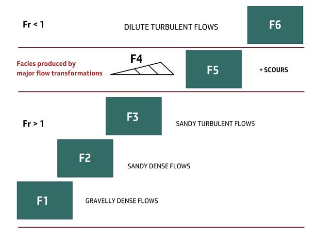
CHAPTER II: Turbidites TURBIDITE SYSTEMS: AN OUTCROP-BASED ANALYSIS 178
Fig. 145 - Rationale behind the subdivision of turbidite sediments into facies groups ranging from gravelly dense flow deposits to sand and mud deposited by waning turbulent suspensions. See text for an extensive discussion.
GRAVELLY DENSE FLOWS
Clasts are mainly supported by an overpressured fluidized matrix which may locally retain some strength; frictional freezing and reworking at the head and margins of flow; hindered settling. F1 deposits.
SANDY DENSE FLOWS
Sand is mainly supported by excess pore pressure and increasing particle collisions toward the base of the flow; en masse deposition by frictional freezing and limited traction; hindered settling. F2 deposits
SUPERCRITICAL TURBULENT FLOWS
Sediment is maintained within the flow by turbulence and sedimentation takes place through fallout and subsequent traction along the bed producing supercritical bedforms F3 deposits.
SUBCRITICAL TURBULENT FLOWS
Sediment is maintained within the flow by turbulence and sedimentation takes place through fallout and subsequent traction along the bed; high rates of fall out may result in structureless sandy divisions. F6 deposits.
VII.8.1.1 - Tectonic mélanges and large-scale mass transport deposits (slumps, slides, blocky flows)
In many basins and associated with the above turbidite groups are relatively thick units of chaotic deposits generally referred to as “mass-transport deposits” (MTDs) which are increasingly recognised in exposed orogenic belt basins as well as portrayed from seismic and marine-geology data from buried and recent
continental margins. Since the pioneering papers of Dott (1963) and Carter (1975), these units have been interpreted as produced by sliding and slumping of poorly consolidated sediments from the shelfedges and slopes bounding deeper-water turbidite basins and were thus considered as strictly genetically associated with turbidite sedimentation in the early facies schemes of Mutti and Ricci Lucchi (1972). Chaotic,
CHAPTER II: Turbidites TURBIDITE SYSTEMS: AN OUTCROP-BASED ANALYSIS 179
FLUID STRENGTH UPWARD FLUID ESCAPE PARTICLE COLLISIONS TURBULENCE PARTICLE SUPPORT MECHANISMS (EXCESS PORE PRESSURE) Cohesive Frictional Fullyturbulent DominantTypeof flow SE TT LING
Fig. 146 - Sketch showing dominant flow types, particle-support mechanisms and particle settling in sediment gravity flows.
Fig. 147 -Main types of flows accounting for transport and deposition of the facies groups as defined herein.
mass transport deposits should be therefore considered as a proximal end member of turbidite sedimentation. Although conceptually correct, several lines of evidence suggest however that the two types of sedimentation are generally distinct, being developed at different physical and temporal scale. Mass-transport processes are rare events displacing huge volumes of sediment at once; turbidity currents are relatively high-frequency events of generally much smaller volume organized in conduits and lobes, thus requiring to be fed by repetitive and similar triggering mechanisms in the source areas.
Recent advances in their description and understanding clearly show that chaotic units cover a wide spectrum of facies ranging from tectonic mélanges formed at relatively deep structural levels as observed in orogenic belts to purely sedimentary deposits typified by frictional debris-flow deposits via a variety of facies recording the transition from deep-seated broken formations and tectonic melanges, dominated by tectonic forces, to
shallower units where gravitational processes dominate (see Festa et al., 2012, for an extensive discussion).
Chaotic units of sedimentary origin comprise a group of deposits ranging from slump and slides to blocky and pebbly mudstones that result from instability processes along basin margins or in basinal “highs” produced by structural deformation (faults, thrusts, salt and mud diapires). In orogenic belt basins allochthonous material, derived from advancing thrust-sheets is commonly involved in these chaotic units.
Some examples of chaotic deposits of both tectonic and sedimentary origin are shown in Figures 148-151. In particular, Figures 150 and 151 show the transition between slumps and cohesive debris-flow deposits, strengthening the concept of a genetic link between mass-transport deposits and turbidites. A useful overview of mass transport sedimentation has been recently provided by Ogata et al. (2014, with references therein).
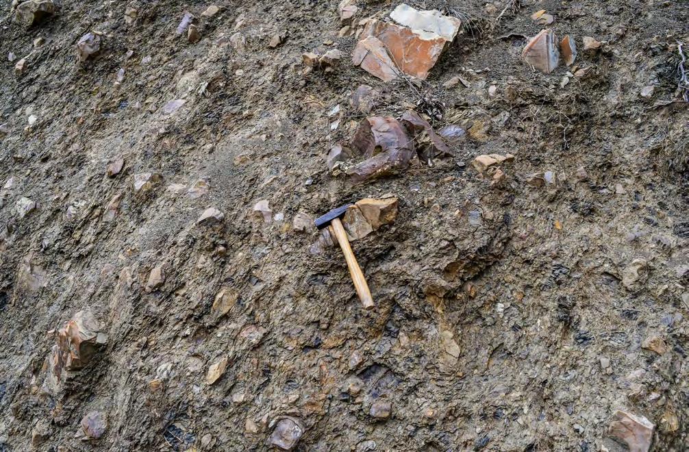
CHAPTER II: Turbidites TURBIDITE SYSTEMS: AN OUTCROP-BASED ANALYSIS 180
Fig. 148 - Typical example of a tectonic melange showing unsorted angular fragments of limestone, sandstone and shale enclosed in a pervasively sheared finer-grained matrix. Oligocene Sanguineto Complex in the Bobbio tectonic window, northern Apennines.
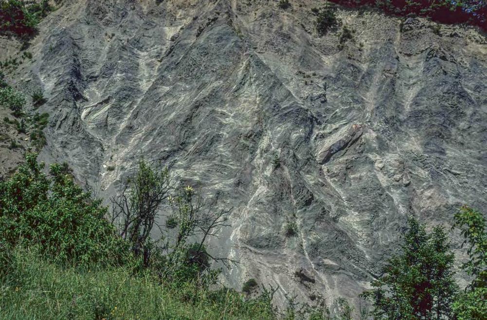
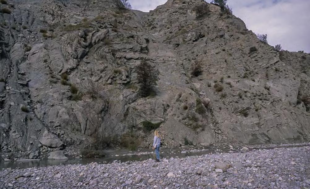
CHAPTER II: Turbidites TURBIDITE SYSTEMS: AN OUTCROP-BASED ANALYSIS 181
5 m
Fig. 149 - Chaotic structure of a mass-transport unit. Disrupted and folded large blocks of sandstone and mudstone are either separated by shear surfaces or by an overpressured finer-grained matrix. The unit can be interpreted as a blocky flow deposit. Upper Eocene-Oligocene Ranzano Sandstone, northern Apennines.
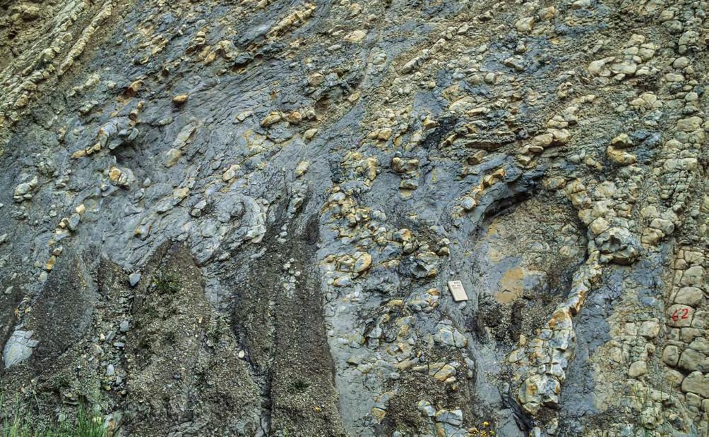
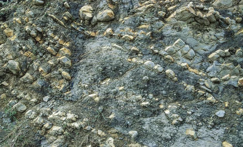
CHAPTER II: Turbidites TURBIDITE SYSTEMS: AN OUTCROP-BASED ANALYSIS 182
Fig. 150 - Slump unit made up of mudstones and nodular limestones passing into a highly cohesive dense flow. Paleocene-Eocene Tremp-Ager Group, south-central Pyrenees.
Fig. 151 - Transition from slump into a cohesive dense flow. Note that the clasts of the flow are represented by limestone nodules. Encircled pencil for scale. Paleocene-Eocene Tremp-Ager Group. South-central Pyrenees.
Cohesive dense flow
Slump
Cohesive dense flow
Slump with shear surfaces
VII. 8.1.2 - F1 and its facies boxes
This group includes matrix-and clast-supported conglomerates and graded pebbly sandstones thought to be the deposit of gravelly dense flows. Matrix can vary from dominantly muddy to mixtures in variable proportions of mud, sand and small gravel. Beds can be ungraded, normally or inversely graded and have variable types of geometry ranging from thick and tabular to thin and lenticular. In general, these beds are devoid of internal stratification but, where they are deposited by long-lasting and powerful flows or are reworked by similarly strong flows in the axial zones of submarine conduits, bedforms develop, giving way to thick parallel and large-scale cross laminae. Since I am not very familiar with this kind of facies, stratified conglomerates and pebbly sandstones are omitted in the following discussion. The interested reader is referred to the paper by Hein and Walker (1982).
The deposits of this group refer to facies and processes that are dealt with in an abundant literature that would be impossible to review herein. Among the many papers, we would like to draw the attention on that of Crowell (1957) in which the reader can find one of the best descriptions of “pebbly mudstones” interpreted to be the deposit of debris flows (Figure 152). The paper was written about 60 years ago and is an outstanding example of how far a geologist can go based on careful and patient field observations.
The origin of most F1 deposits is traditionally associated with the concepts of “debris flow” and “hyperconcentrated flow”, i.e., dense mixtures of sediment and water were the clasts are supported within the flow by the interaction of matrix strength, buoyancy, grain-tograin collisions, and excess pore pressure (Middleton and Hampton, 1973; Lowe, 1982; Pickering et al., 1989; Mutti, 1992; Iverson, 1997; Mulder and Alexander, 2001; Talling et al., 2012).
Following Lowe (1982) and Mutti (1992), we think that cohesive debris flows are an end member of this broad family and a type of flow in which the larger clasts are entirely sustained within the flow by buoyancy and the cohesiveness of the clay-water matrix. The
deposits of these flows are denoted with F1-1 and consist of ungraded units of extremely poorly sorted clasts floating in a mudstone matrix which is typically plastically deformed. Most commonly, these sediments are found in carbonate turbidites developed in ramp or block-faulted settings forming breccias or paraconglomerates where the clasts are quite often early diagenetic nodules disrupted by extensional or compressional boudinage (Figures 153 and 154).
In terrigenous successions F1-1 deposits are rarely observed either because this type of cohesive flows does not form, or they immediately mix with water and transform into more mobile flows with a fluidized matrix. The most common deposits of Group 1 associated with terrigenous successions are shown by facies boxes termed F1-2 and are here interpreted as the deposits of gravelly dense flows transitional between cohesive debris flows (see above) and fluidized flows in the sense of Lowe (1979), i.e., flows in which the coarse particles are sustained by both matrix strength and density and escaping pore fluid (fluidized matrix with excess pore pressure and strength).
Facies boxes of F1-2 deposits (Figures 155-158) show the typical expression of these flows resulting in beds of poorly sorted and ungraded pebbly and cobbly mudstones with a fully mixed and liquefied matrix consisting of a mixture of mud, sand, and small gravel. Some beds contain large blocks, up to several meters across, of slope mudstones with thin bedded sandstones or thick-bedded turbidite sandstones which are typically deformed into tight isoclinal folds whose cores are injected by a fluidized matrix. High matrix strength may be preserved toward the top of some flow producing passively moving “rigid plugs” (sensu Middleton and Hampton, 1973) containing large floating blocks (Figure 156).
As noted by Mutti (1992), these beds record transport and deposition by extremely powerful and erosive flows probably recording the phase of “catastrophic erosion” and bulking suggested by Parker (1982) for the early ignitive phase of turbidity currents. Among turbidite facies, these beds are certainly those suggesting the most catastrophic character of the formative flow.
CHAPTER II: Turbidites TURBIDITE SYSTEMS: AN OUTCROP-BASED ANALYSIS 183
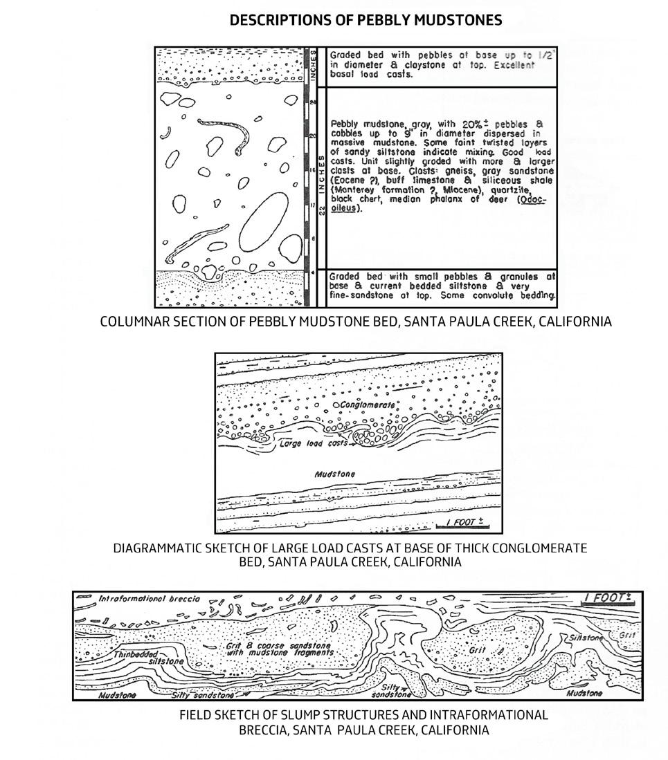
CHAPTER II: Turbidites TURBIDITE SYSTEMS: AN OUTCROP-BASED ANALYSIS 184
Fig. 152 - Description of a pebbly mudstone and associated deposits by Crowell (1957, his Figures 6,7, and 8, p.1001).
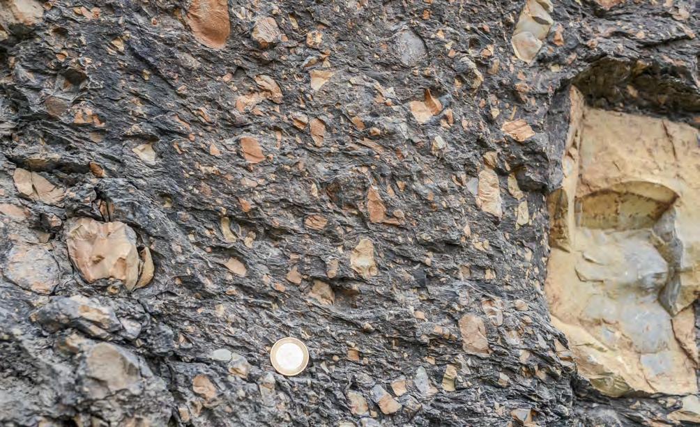
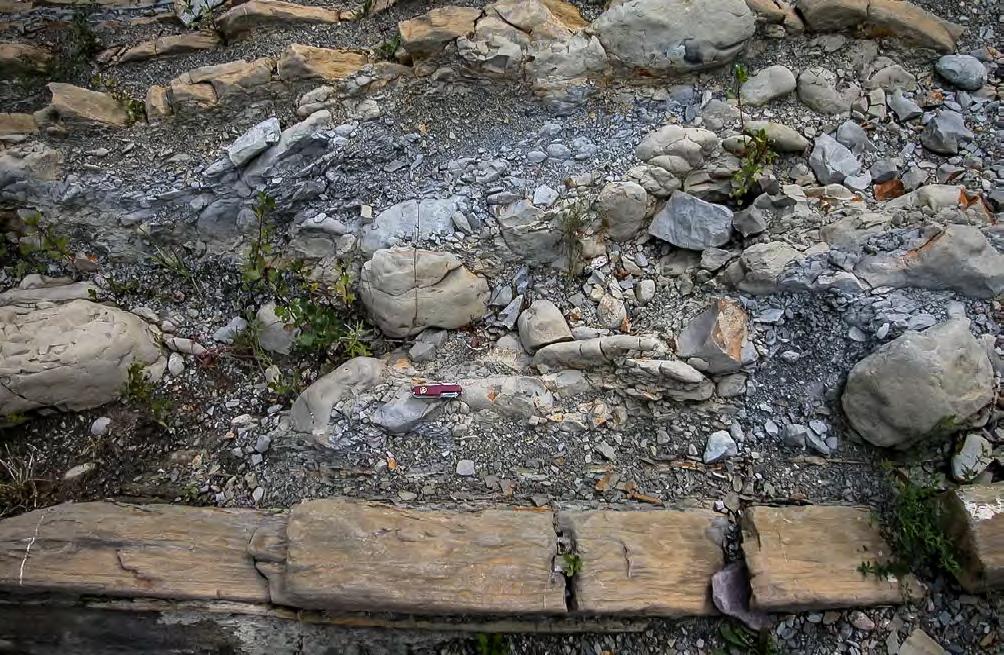
CHAPTER II: Turbidites TURBIDITE SYSTEMS: AN OUTCROP-BASED ANALYSIS 185
Fig. 153 - Very poorly-sorted carbonate breccia with a dark muddy matrix. Cretaceous Palombini Limestone, northern Apennines.
Fig. 154 - Cohesive debris-flow deposit. Clasts float in a muddy matrix and consist of early-diagenetic nodules derived from adjacent slope sediments. Santonian Vallcarga Formation, south-central Pyrenees.
F1-1
F1-1

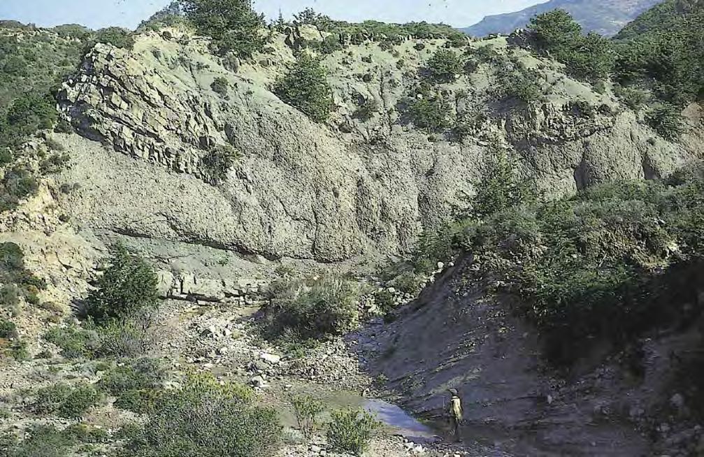
CHAPTER II: Turbidites TURBIDITE SYSTEMS: AN OUTCROP-BASED ANALYSIS 186
Fig. 155 - Large mudstone clasts (slope sediments) floating in a fluidized matrix of fully mixed mud, sand, skeletal material, and scattered pebbles. Eocene Hecho Group, south-central Pyrenees.
Fig. 156 - Classic “pebbly mudstone” with large folded blocks of intraformational turbidite sandstones (indicated by arrow) forming the “rigid plug” of the flow. Oligocene Messanagròs Sandstone, Island of Rhodes, Greece (from Mutti, 1992).
F1-2
F1-2
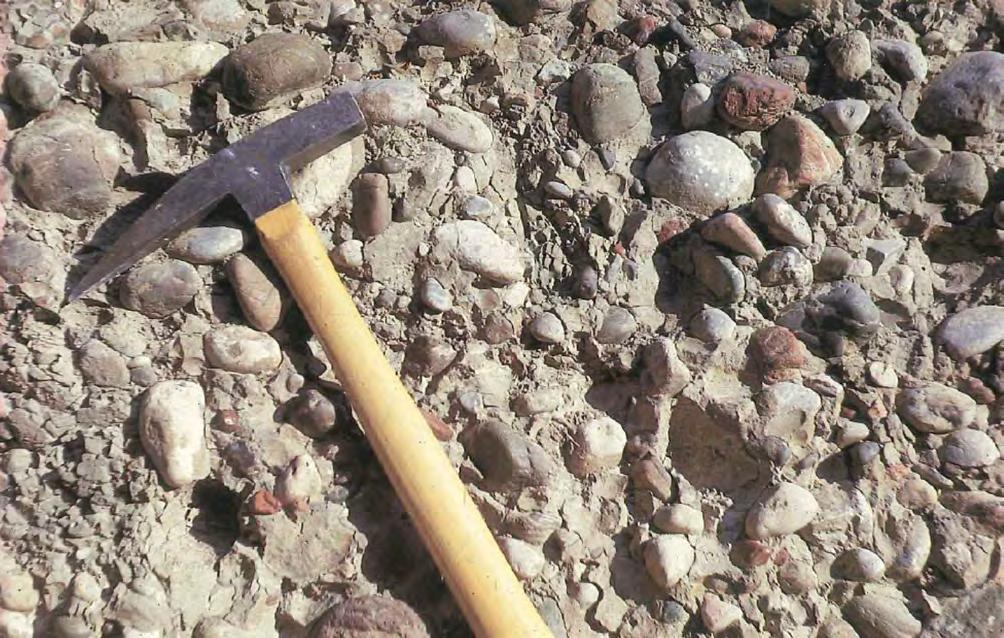
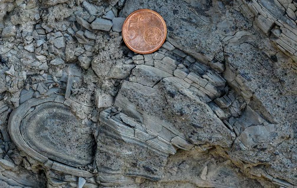
Folded clast of slope mudstone
CHAPTER II: Turbidites TURBIDITE SYSTEMS: AN OUTCROP-BASED ANALYSIS 187
Fig. 157 - Pebbles floating in a muddy-sandy matrix. Detail of Figure 156.
Fig. 158 - Folded clasts of slope mudstones enclosed in and injected by a liquefied poorly sorted matrix. Eocene Hecho Group, south-central Pyrenees.
F1-2
MATRIX Macroforam
F1-2
Boxes of F1-3 shows beds similar to those of F1-2 but characterized by the beginning of grading (Figure 159). Coarsest clasts tend to collect toward the base of the bed though some blocks may still float toward the top. We interpret these beds as the deposit of flows in which the cohesiveness of the matrix and buoyancy are decreasing, allowing the settling of the coarsest clasts toward the base of the flow and thus forming a faster-moving frictional flow undergoing rapid dewatering. After frictional freezing, the clast-supported conglomerates would be overlain by the matrix-rich deposit of the more cohesive portion of the flow.
For progressive loss of matrix strength and excess pore pressure for settling (sea above) and along the leading edges of the flow, the sediments above pass into clast-supported conglomerates deposited through frictional freezing (F1-4). Facies boxes of Figures 160161 illustrate some examples of this kind of deposit, generally forming residual lags at the base of erosional features after a major flow transformation. Most commonly they occur as amalgamated bodies characterized by extensive scouring. Bedforms are diffcult to observe, though large cyclic steps might play here a major role. Mud-clast breccias (sensu Mutti et al., 2003) are sometimes found at the base of these units, suggesting impact of the edge of the flow on a mud substratum. Figure 162 shows both F1-3 and F1-4 facies spaced vertically only a few meters within the same stratigraphic unit.
Facies boxes shown in Figures 163-165 describe a significantly different type of deposit consisting of disorganized and extremely poorly sorted conglomerates with relatively small amounts of a finer-grained matrix that is essentially free of mud (F1-5). Boulders, cobbles and pebbles form clusters suggesting successive sediment waves. Imbrication may be common and in some cases the deposit shows evidence of either shearing from an upper flow or post-depositional downslope flowage.
This kind of facies is apparently restricted to small, high-gradient and very poorly efficient systems directly fed by alluvial-fans or fan-deltas. These conglomerates are usually capped by strutureless and coarse-grained sandstone divisions suggesting deposition from inertia-dominated, frictional dense flows moving ahead of more dilute flows. The process envisaged herein is very similar to that suggested by Sohn et al. (1999) for some flood-flows in alluvial fans, where the deposits of frictional, inertia-driven debris
flows are successively overlain by those of hyperconcentrated flows and eventually streamflows (Figure 166). Clearly, there must be all the gradational facies between the deposits of dominantly cohesive or dominantly frictional dense gravelly flows.
Figures 167-172 show some examples of graded pebbly sandstones. This facies, which is very common in turbidite successions and still poorly described and understood, essentially consists of beds where a basal pebbly and cobbly division is overlain by sandy divisions that can be either internally stratified or structureles. The basal conglomeratic division is either characterized by inverse-to-normal grading and convex-upward types of geometry at outcrop scale (F1-6) or by a disorganized structure of very poorly sorted coarse clasts (F1-7). In the first case, basal scours and mudstone clasts are very common.
F1-6 pebbly sandstones are probably supercritical bedforms generated at the final leading edges of frictional dense flows. The orientation, spacing and geometry of these bedforms is difficult to establish in outcrop. The association with well-developed traction carpets laterally and above these features might suggest a cyclic-step origin. The best descriptions of this type of facies is still that of Hein and Walker (1982) from the Cambro-Ordovician Cap Enragé Formation, Quebec, Canada, showing the complexity of these sediments and the variety of their geometry types and erosional and depositional features. These sediments were apparently deposited by powerful and efficient flows which were able to produce supercritical bedforms during their bypassing phase. These beds commonly include a basal division of rip-up mudstone clasts (impact breccia, see above). If the reader is up for a crazy idea, these convex-upward conglomerate lenses sharply capped by finer-grained deposits bear some strange resemblance to the terminal noses of the dense flow deposit shown in Figure 173.
F1-7 pebbly sandstones are more immature deposits where poorly sorted and internally unstratified crudely graded or ungraded conglomerates, with variable amounts of matrix, are abruptly overlain by structureless sandstone. The lack of tractional features suggests “en masse” deposition for frictional freezing of poorly efficient flows. Sharp bypass surfaces at the top of conglomerate layers are generally absent. Figure 174 compares the two end members of graded pebbly sandstones. Also, in the case of graded pebbly sandstones there must be a spectrum of transitional facies.
CHAPTER II: Turbidites TURBIDITE SYSTEMS: AN OUTCROP-BASED ANALYSIS 188
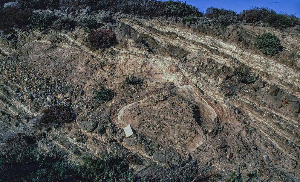
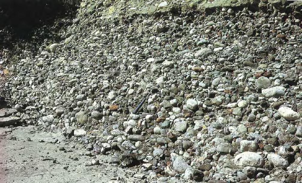
CHAPTER II: Turbidites TURBIDITE SYSTEMS: AN OUTCROP-BASED ANALYSIS 189
Fig. 159 - Graded pebbly mudstone. Loss of flow strength has allowed for the settling of the coarsest clasts at the base of the flow, probably forming a faster moving frictional flow. Note the large folded block (note book for scale). Oligocene Messanagròs Sandstone, Island of Rhodes, Greece.
Fig. 160 - Clast-supported conglomerates segregated from an originally cohesive gravelly flows and deposited through frictional freezing. Oligocene Messanagròs Sandstone, Island of Rhodes, Greece (encircled hammer for scale) (from Mutti, 1992).
F1-3
F1-4
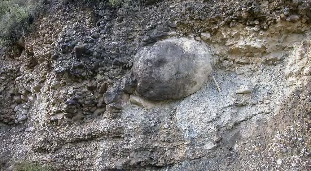
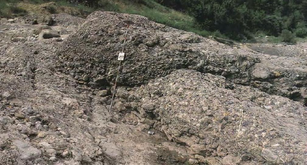
VII. 8.1.3 - F2 and its facies boxes
We include in this group a great variety of sediments having in common a diagnostic structureless or “massive” division and a relatively coarse-grained and poorly sorted texture (Figures 175-177), locally including granules and small pebbles. Beds have an overall tab-
ular geometry though basal scours and amalgamation are common.
Thicker beds (up to several meters) are most commonly overall graded and generally contain multiple scours and associated traction carpets (F2-1, see Figures 178-186). Unless large exposures are available, the occurrence of
CHAPTER II: Turbidites TURBIDITE SYSTEMS: AN OUTCROP-BASED ANALYSIS 190
Fig. 161 - Clast-supported conglomerates deposited by frictional gravelly flows. Stacking of these beds results in highly irregular patterns with lensing and scouring. Eocene Gerbé-Cotefablo system, Hecho Group, south-central Pyrenees.
F1-4
F1-4
multiple scours within the same bed can be often mistaken for successive amalgamation surfaces. The infill of scours and traction carpets are coarser-grained than the enclosing deposit and may consist, in some cases, of fine conglomerates. An excellent description of similar beds was provided by Hein and Walker, 1982, from the Cambro-Orovician Gaspé Peninsula, Quebec (Figure 187). Typically, depth and width of the scours and the thickness of the traction carpets decrease upward
along with a grain-size fining. Especially at the base of thick beds, after infilling the basal scour or a series of scours, coarse-grained sediment aggrades forming broadly lenticular, convex-upward units, which, in small outcrops, can be mistaken for tabular bodies. Clearly, except for the finer grain size, these beds share many similarities with the F1-6 graded pebbly sandstones (see above), suggesting once again the natural transitional character of facies and processes.
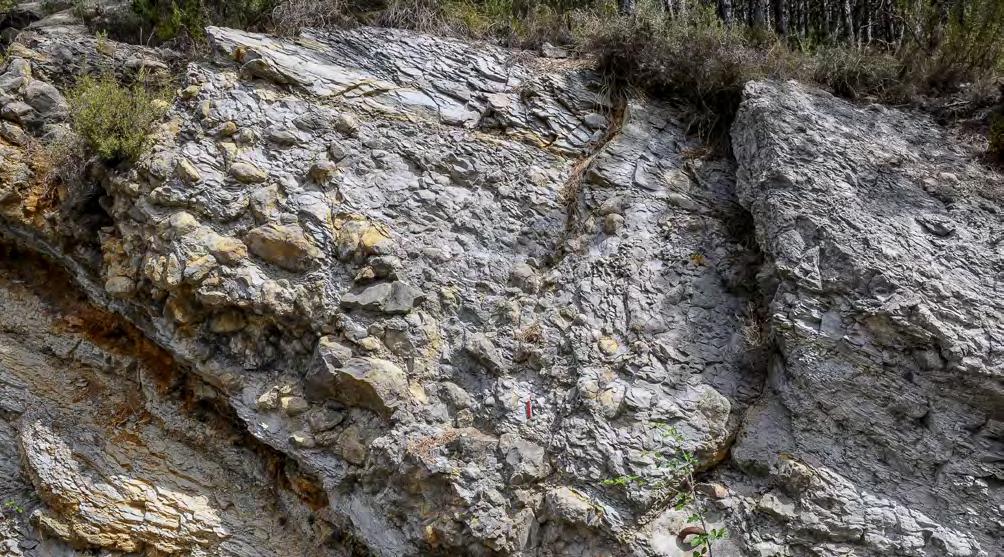
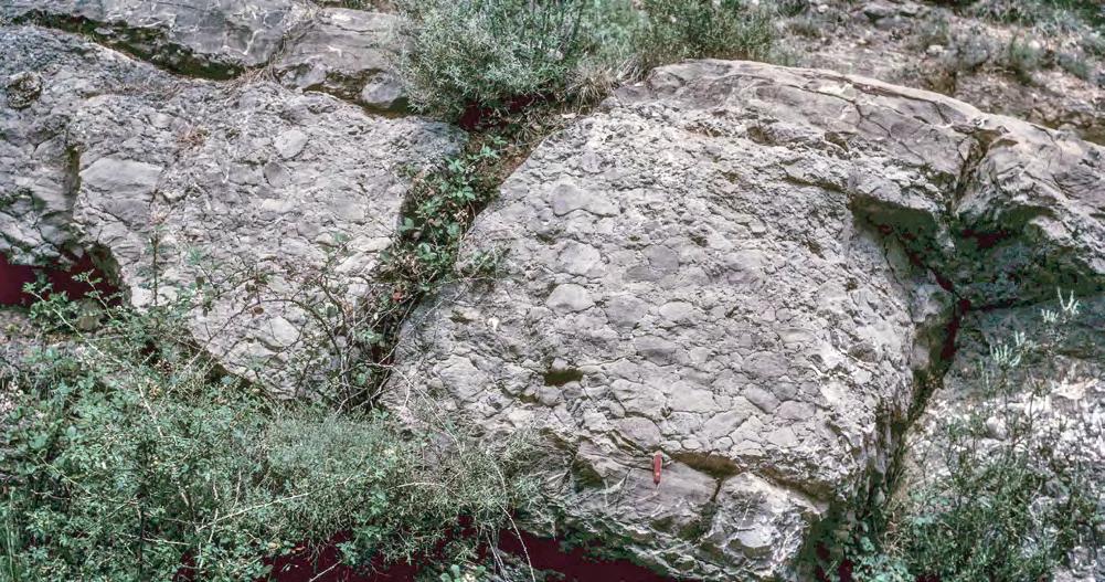
CHAPTER II: Turbidites TURBIDITE SYSTEMS: AN OUTCROP-BASED ANALYSIS 191
Fig. 162 - Examples of cohesive (F1-3) and frictional (F1-4) debris flow deposits from the upper Cretaceous Vallcarga Formation, south-central Pyrenees. The two types of facies are thought to be intergradational.
F1-3
F1-4
F1-5
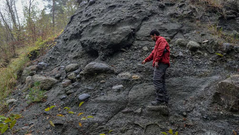
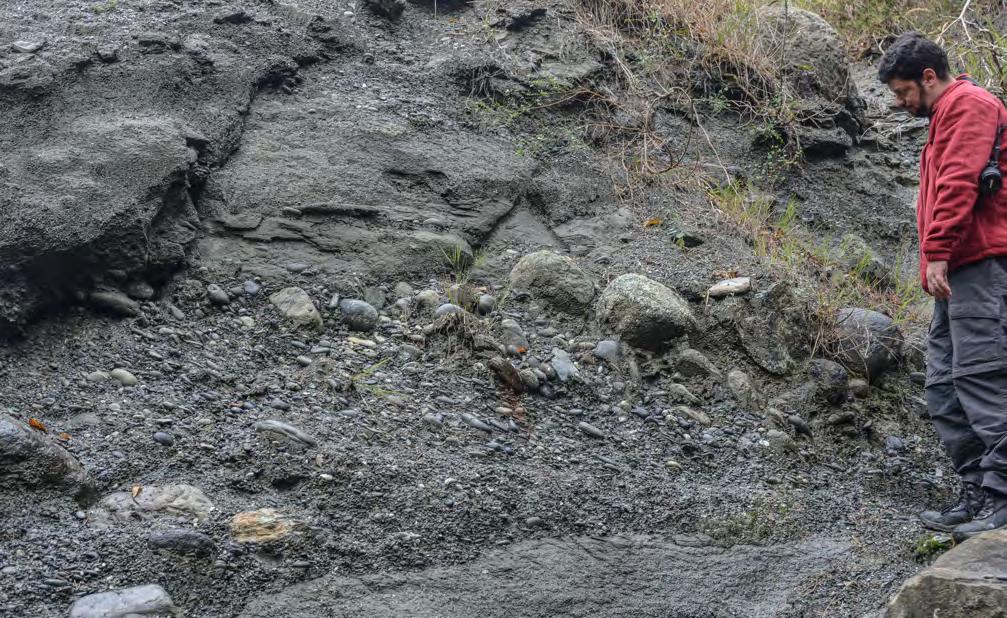
CHAPTER II: Turbidites TURBIDITE SYSTEMS: AN OUTCROP-BASED ANALYSIS 192
Fig. 163 - Gravelly dense-flow deposits with virtually mud-free matrix. Note scouring surfaces and successive sediment waves forming coarse clastic clusters. Flow direction is to the left. Oligocene Budroni system, Tertiary Piedmont Basin.
Fig. 164 - Detail of Figure 163 showing pebble imbrication. Flow is from right to left.

Other beds, usually thinner (0.5-1 m) and finer grained, herein referred to as F2-2, (Figures 188-197), are made up of a stuctureless, crudely graded division comprising most of the thickness of the bed (see facies F5 of Mutti, 1992) which are in most cases capped by a thin ripple-division, which is more rarely underlain by thin parallel laminae, through a bypass surface. These beds are very common and typically comprise spectacular successions of parallel-sided beds separated by thin shaly partings in lobe regions (Figure 195). Other beds may show a main structureless division capped by thick parallel laminae (traction carpets?) produced by supercritical flows (F2-3). In all the above cases, sedimentation culminates with fine-grained deposits laid down by the tail of the flow. Apparently, there is a spectrum of facies indicating a process through which dense flow structureless deposits may be gradually replaced in space and with time by crudely or well-developed parallel laminae produced by settling from an overlying suspension, be this subcritical or supercritical, followed by some traction along the bed. Talling et al. (2012) argue instead that the reversal is true, but they probably refer to finer-grained deposit of turbulent suspensions and to sudden variations in rates of sediment fallout (see later).
Among the many problems encountered in turbidite facies analysis, the one raised by these sandstone facies is particularly relevant not only because most turbidite reservoir sands apparently belong to this category of deposits but also because the origin of their “massive” or “structureless” character is unclear and therefore debated. Their interpretation thus varies between basal “traction carpets” impelled from an overlying and faster moving suspension (e.g., Postma et al., 1988), and inertia-driven and overpressured dense layers moving independently from and faster than an overlying suspension (e.g., Mutti et al., 1999). These dense layers may represent part the original flow since the beginning of the process (thus herein termed primary dense flows), or form later from the settling imposed by density stratification and turbulence damping (thus herein termed secondary dense flows). In the second case, apparently favoured in the schemes of Kneller and Branney (1995), Cantero et al. (2012), and Talling et al. (2012), all the particles were originally transported by a turbulent flow and simply aggrade through settling of individual particles or in a layer-upon-layer fashion. A type of secondary dense flow can also develop from reconcentration of an expanded dense flow after a hydraulic jump (see Figure 139 B).
CHAPTER II: Turbidites TURBIDITE SYSTEMS: AN OUTCROP-BASED ANALYSIS 193
Fig. 165 - Typical 1-F5 conglomerate with sediment waves. Flow is to the left. Oligocene Roboaro System. Tertiary Piedmont Basin. Encircled knife for scale.
F1-5
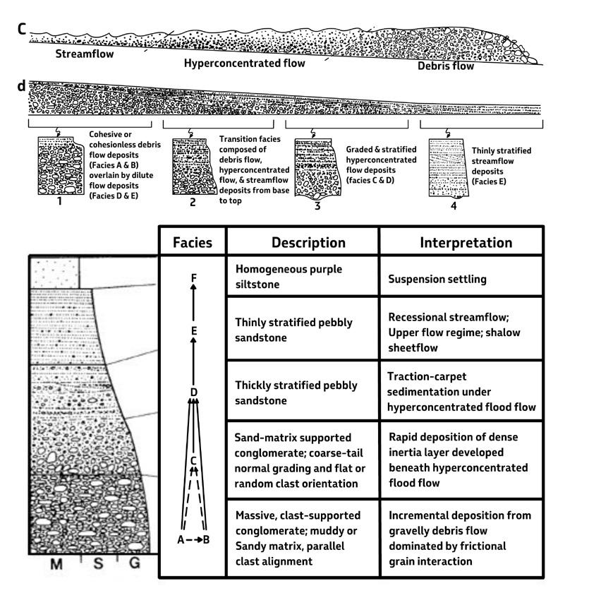
I think that the very poor sorting, the lack of current laminae and the common occurrence of water escape features developed at different scales favour an origin from dense sandy flows under conditions of excess pore pressure. Particularly in confined settings, where these beds may reach considerable individual thickness, large-scale water escape structures are very common.
Deposition would occur “en masse”, or through successive sediment waves, and results from frictional freezing due to the progressive loss of excess pore pressure from elutration. The residual excess pore
pressure, which may be retained after deposition, is still sufficient to generate diffuse water-escape features and to plastically deform the overlying and finegrained current-laminated divisions particularly if the bed is capped by an impervious mudstone division (Figure 198). In other cases, there seems to be a gradual and complete loss of the excess pore pressure before the deposition of finer-grained current laminated sandstone and siltstone (Figures 199-200). Most of these beds are eventually capped, through a grain size break indicating sediment bypass, by the dilute tail of the flow.
CHAPTER II: Turbidites TURBIDITE SYSTEMS: AN OUTCROP-BASED ANALYSIS 194
Fig. 166 - The model of Sohn et al. (1999) for the interpretation of flood-flow deposits in an alluvial fan. An inertia-driven frictional debris flow moves ahead of an hyperconcentrated flow followed by a supercritical streamflow. The deposit is capped by suspension mudstones. Note the reversal of the longitudinal grading from the transport stage to the depositional stage (from Sohn et al., 1999).
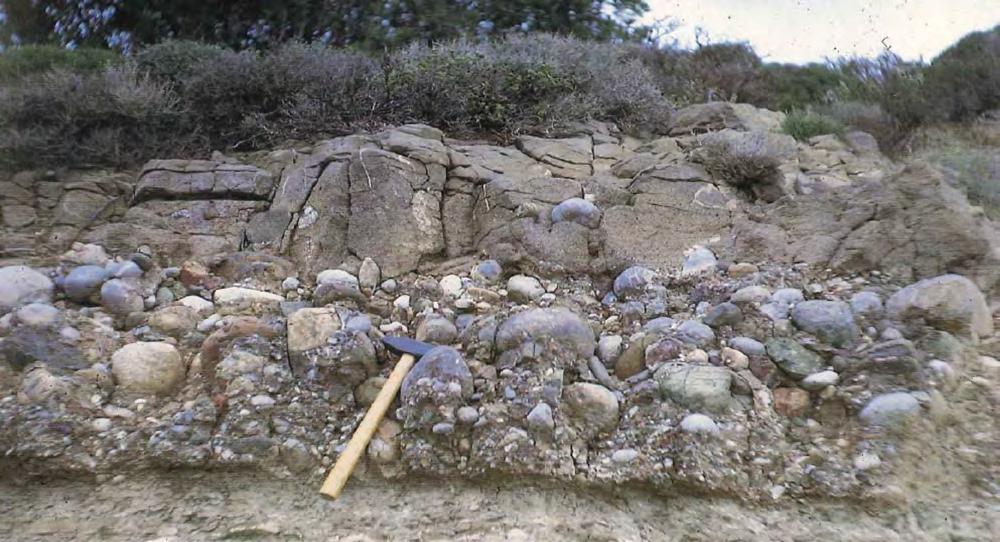
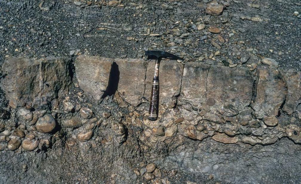
CHAPTER II: Turbidites TURBIDITE SYSTEMS: AN OUTCROP-BASED ANALYSIS 195
Fig. 167 - Inversely to normally graded division of clast-supported conglomerate sharply overlain by crudely- laminated sandstone with dispersed pebbles (arrows). Oligocene Messanagròs Sandstone, Island of Rhodes, Greece.
Fig. 168 - Graded pebbly sandstone. Note crude lamination in the sandstone division with dispersed pebbles at the base. Note also the pinching out of the conglomerates to the right. Eocene Banastòn system, Hecho Group, south-central Pyrenees.
F1-6
F1-6
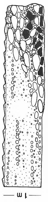
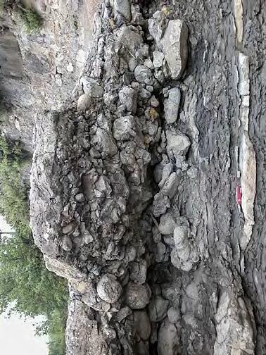
Fig. 169Small and laterally discontinuous graded pebbly sandstone in which a convex-upward lens of clast-supported pebbles and cobbles with an erosional base and shale clasts passes laterally into traction carpets. Through a bypassing surface, the unit is capped by ripples. Eocene Hecho Group, south-central Pyrenees.
CHAPTER II: Turbidites TURBIDITE SYSTEMS: AN OUTCROP-BASED ANALYSIS 196
F1-6
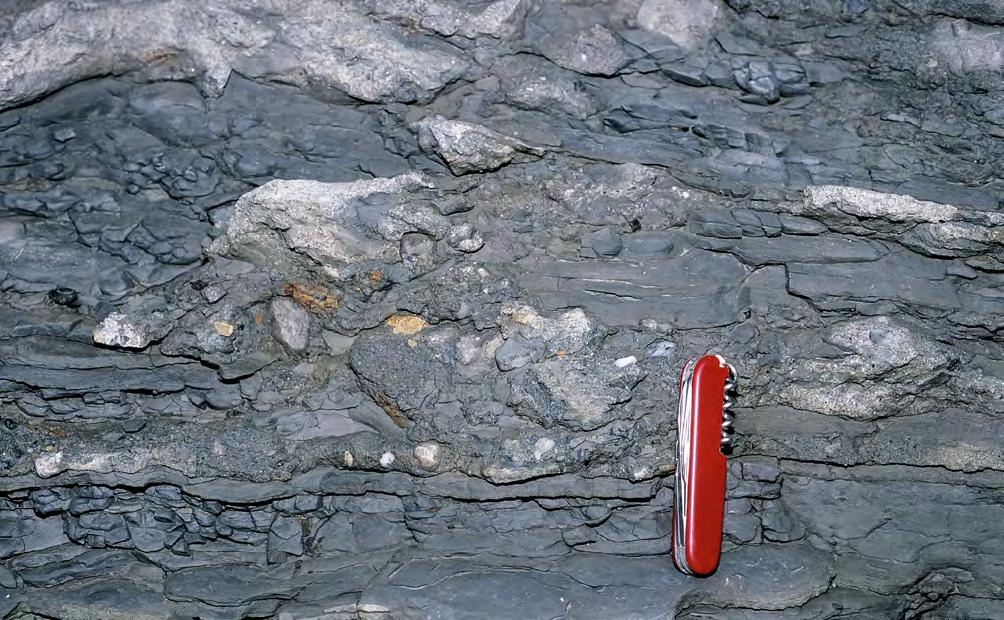

Upcurrent dipping
Convex-upward conglomeratic
CHAPTER II: Turbidites TURBIDITE SYSTEMS: AN OUTCROP-BASED ANALYSIS 197
Fig. 170 - Detail of Figure 169 showing underlying mudstones injected by coarse-grained matrix at the base of the pebbly sandstone (impact breccia).
Fig. 171 - Graded pebbly-sandstone probably associated with a hydraulic jump (see also Fedele et al., 2016, their Figure 25). Eocene Ainsa system, Hecho Group, south-central Pyrenees.
F1-6
coarse-grained cross strata with pebbles and shale clasts
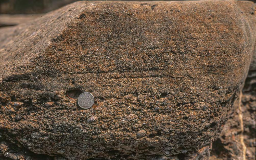
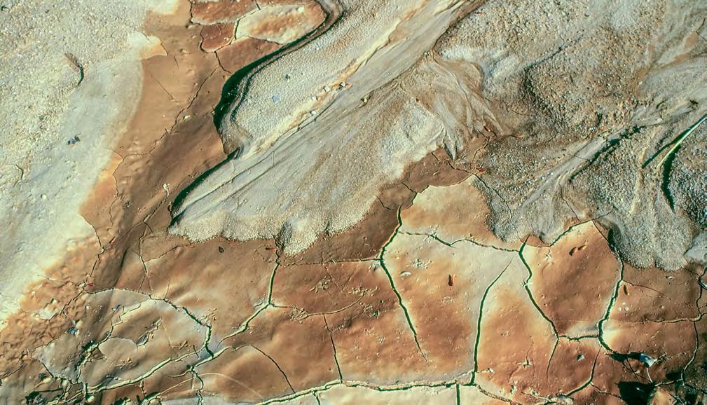
CHAPTER II: Turbidites TURBIDITE SYSTEMS: AN OUTCROP-BASED ANALYSIS 198
Fig. 172 - Graded pebbly sandstone consisting of a basal clast-supported small-pebble division sharply overlain by a sandstone division with traction carpets. Eocene Hecho Group, south-central Pyrenees.
Fig. 173 - Sharp and lobate termination of dense flow deposit observed in a pond after a heavy rain. Suspension deposits with mud cracks and bird tracks drape the coarse-grained minidelta. Near Tremp, Catalonia, Spain.
F1-6
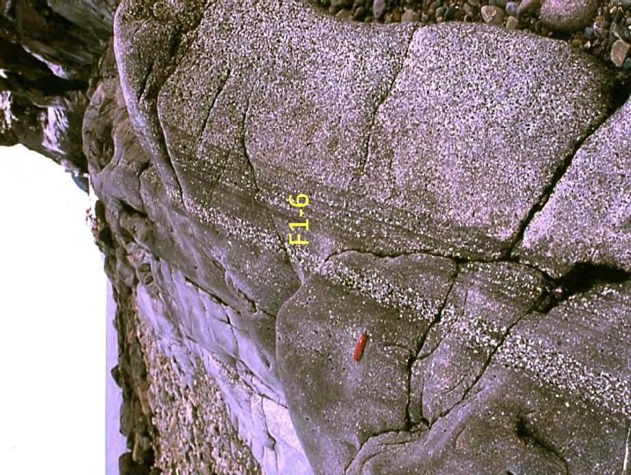
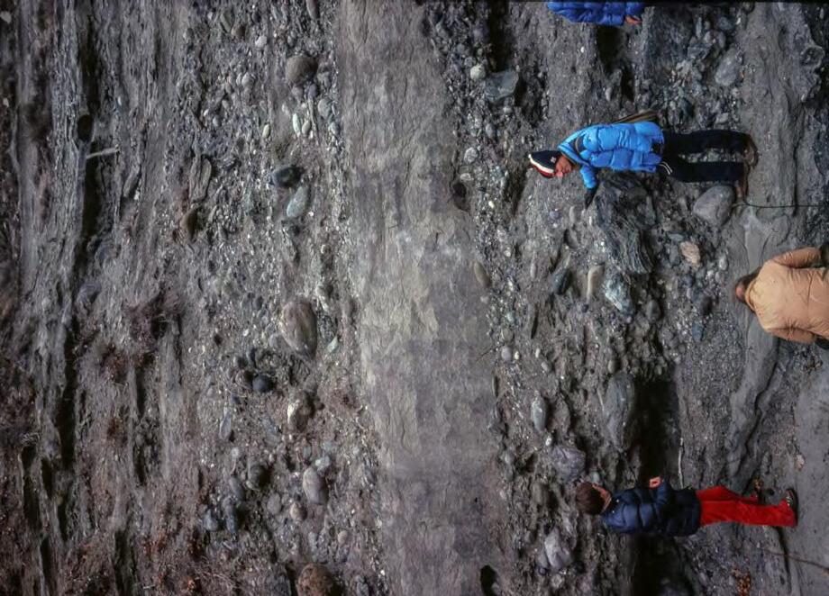
Fig. 174A. Poorly-sorted and internally-unstratified graded pebbly sandstones, Tertiary Piedmont Basin, northern Italy; B. Well-sorted and internally-stratified graded pebbly sandstone, Cambro-Ordovician Cap Enragé Formation, Canada. Note the differences in sorting and internal organization resulting from different flow types.
CHAPTER II: Turbidites
SYSTEMS: AN OUTCROP-BASED ANALYSIS 199
B A
TURBIDITE
F1-7
F1-6
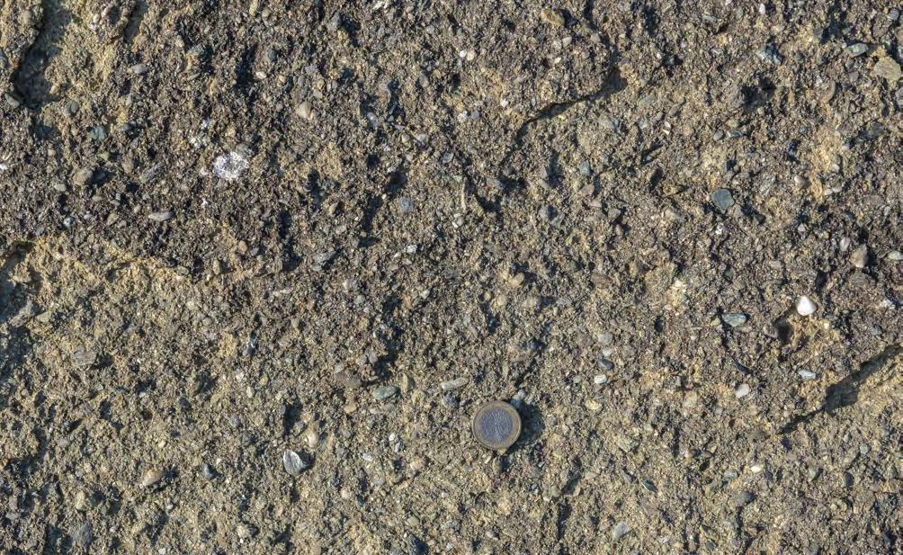
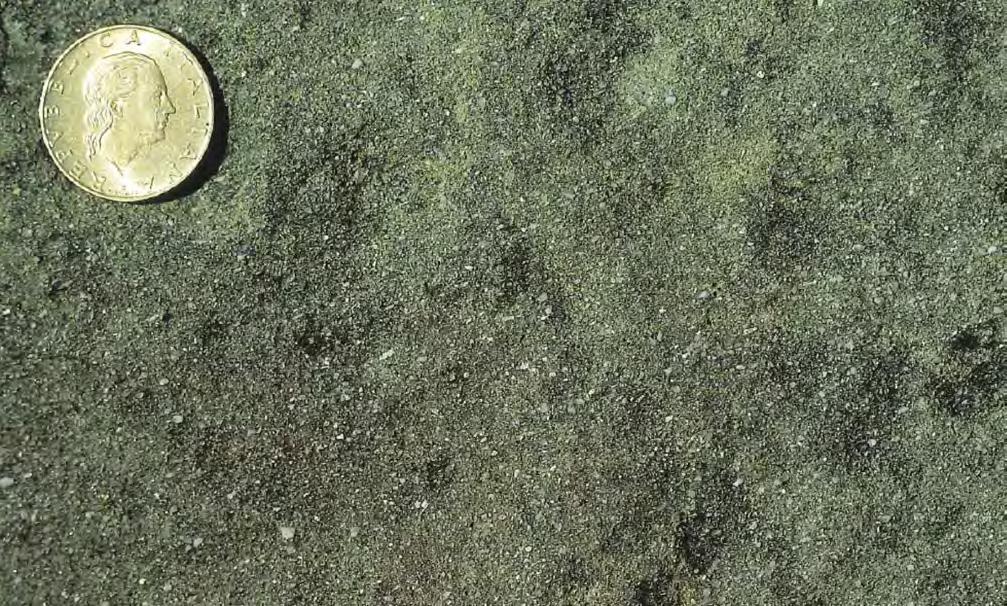
CHAPTER II: Turbidites TURBIDITE SYSTEMS: AN OUTCROP-BASED ANALYSIS 200
Fig. 175 - Typical poorly-sorted texture (with granules and very small pebbles) of structureless sediments of F2. Oligocene Mioglia system, Tertiary Piedmont Basin.
Fig. 176 - Poorly-sorted structureless sandstone of F2. Oligocene-Early Miocene Cervarola Sandstone, northern Apennines.
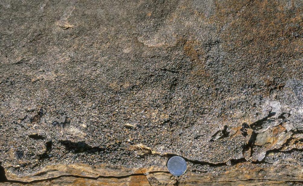
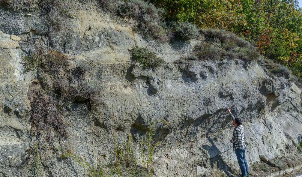
CHAPTER II: Turbidites TURBIDITE SYSTEMS: AN OUTCROP-BASED ANALYSIS 201
Fig. 177 - Graded, poorly-sorted coarse sandstone (F2) with mudstone clasts at the base of the bed. Note lack of internal structures. Eocene Banastòn system, south-central Pyrenees.
F2
Fig. 178 - F2-1 beds. Note multiple scours and the slightly convex-upward upper surface of the basal conglomeratic sandstone. Lower Miocene Noceto system, Tertiary Piedmont Basin.
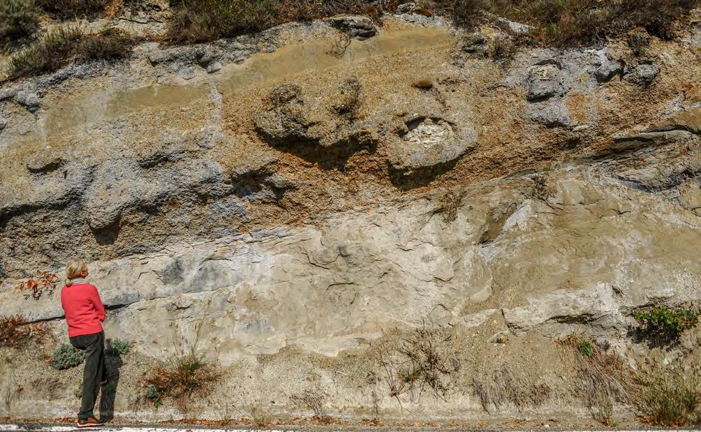
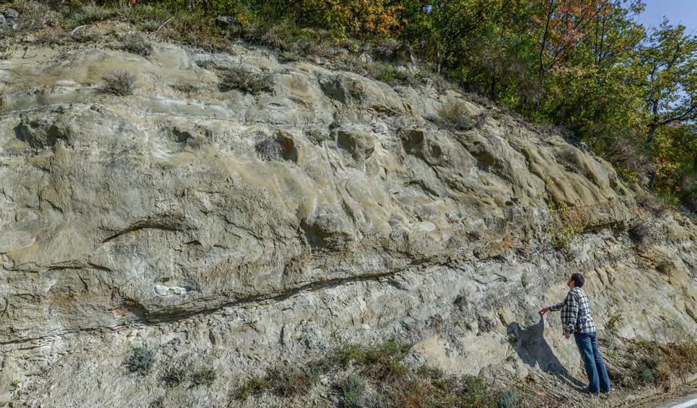
CHAPTER II: Turbidites TURBIDITE SYSTEMS: AN OUTCROP-BASED ANALYSIS 202
Fig. 179 - Structureless sandstone with thick laterally discontinuous basal units of structureless or crudely cross-stratified small pebble-size conglomerates and traction carpets (F2-1). Lower Miocene Noceto system, Tertiary Piedmont Basin.
Fig. 180 - F2-1 beds. Note the pinching out to the left of a basal coarser-grained division. Thick structureless sandstone beds display water escape features and multiple scours. Lower Miocene Noceto System, Tertiary Piedmont Basin.
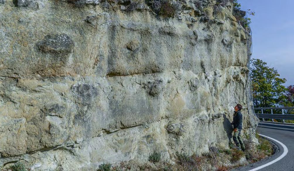
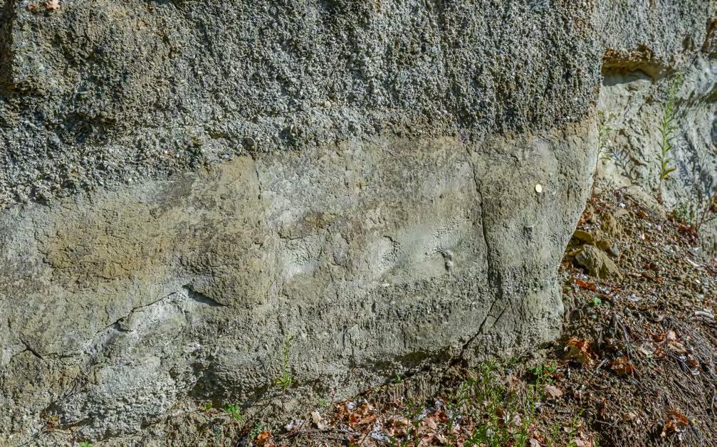
CHAPTER II: Turbidites TURBIDITE SYSTEMS: AN OUTCROP-BASED ANALYSIS 203
Fig. 181 - Typical example of parallel-sided and amalgamated F2-1 beds with basal scours passing laterally and vertically to traction carpets. Fill of scours and traction carpets made of very coarse sandstone and granule conglomerate. Note crude lamination and dewatering features in upper divisions. Lower Miocene Noceto system, Tertiary Piedmont Basin.
Fig. 182 - Traction carpets in F2-1 beds. Lower Miocene Noceto system, Tertiary Piedmont Basin.
Scour
Traction carpets
Traction carpets
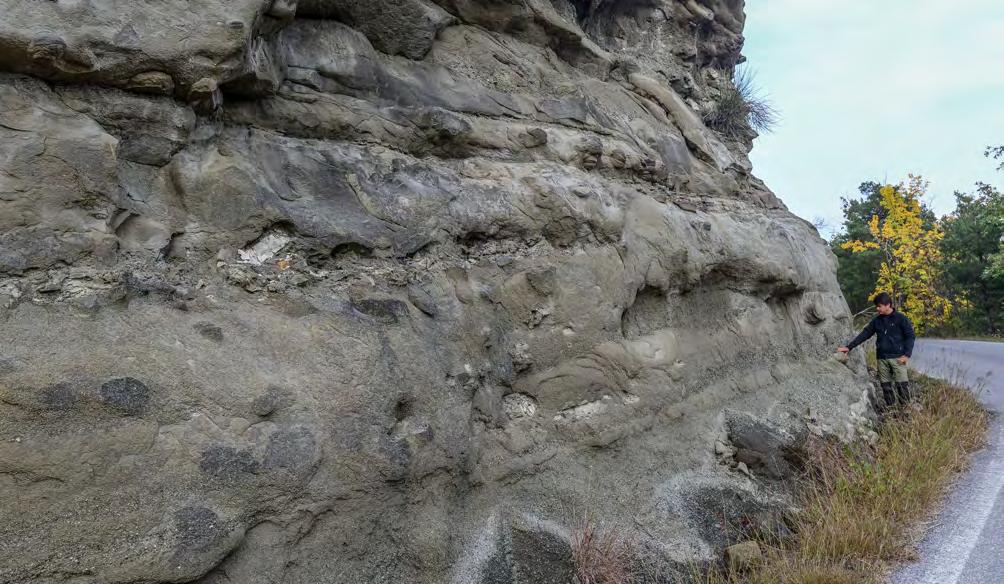
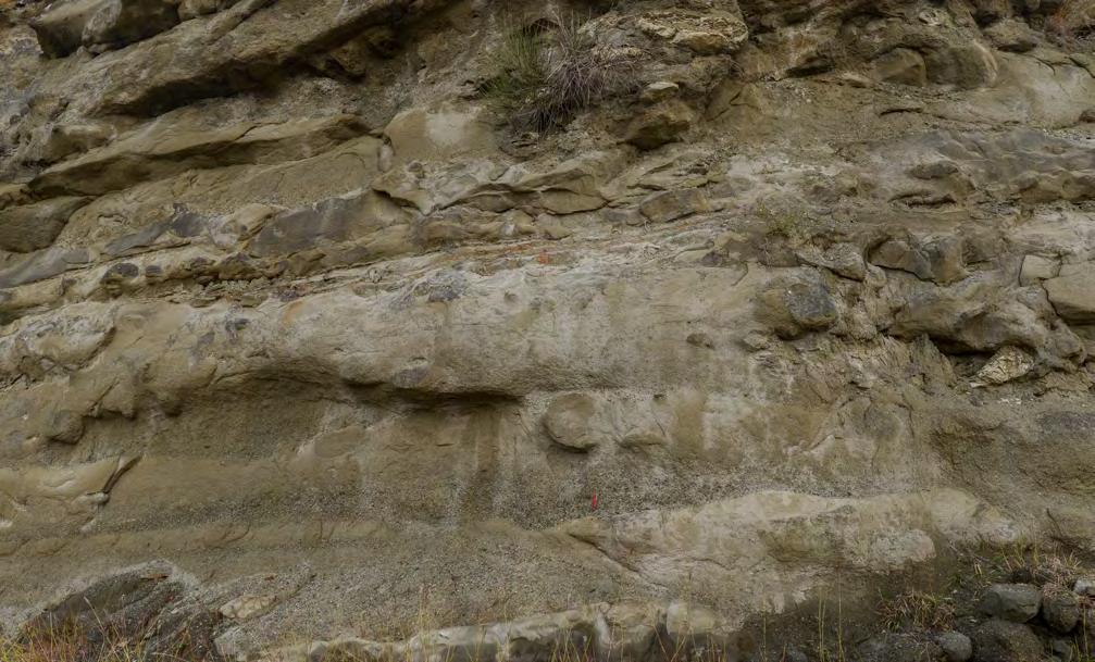
CHAPTER II: Turbidites TURBIDITE SYSTEMS: AN OUTCROP-BASED ANALYSIS 204
Fig. 183 - Amalgamated structureless sandstone beds showing repeated scours filled in with finely conglomeratic sandstone and associated traction carpets and shale clasts (F2-1). Lower Miocene Rapalino system, Tertiary Piedmont Basin.
Fig. 184 - Structureless sandstone beds with scours and traction carpets (F2-1). A bed in the middle shows an upward transition into thick parallel laminae. Swiss knife indicated by arrow. Lower Miocene Rapalino system, Tertiary Piedmont Basin.
Shale clasts
Scour
Traction carpet
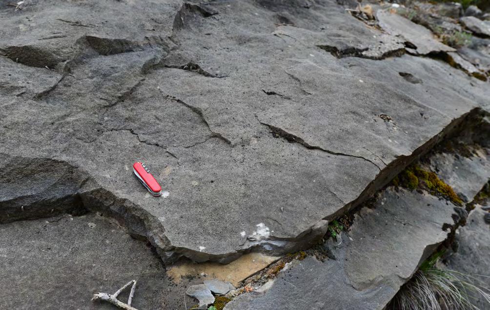
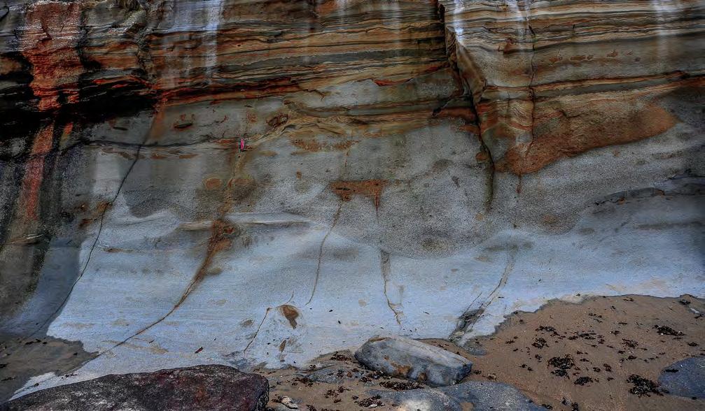
CHAPTER II: Turbidites TURBIDITE SYSTEMS: AN OUTCROP-BASED ANALYSIS 205
Fig. 185 - Thick structureless sandstone bed with basal multiple scours (F2-1). Eocene Banastòn system, south-central Pyrenees.
Fig. 186 - Multiple scours (indicated by arrow) filled with medium to coarse sandstone (F2-1). Japaratinga, Sergipe-Alagoas Basin, Brazil.
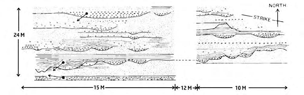
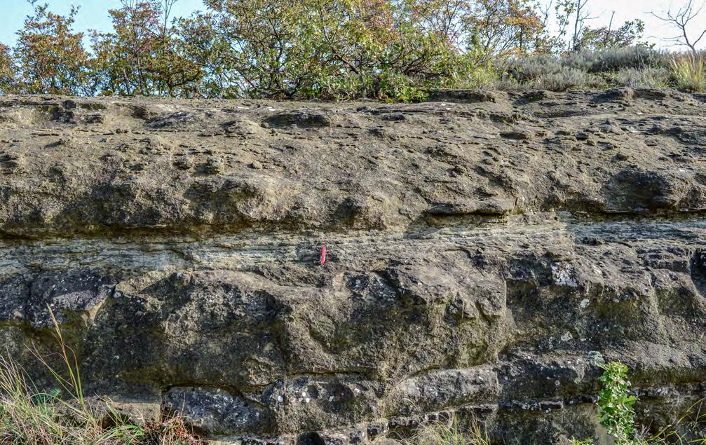
CHAPTER II: Turbidites
SYSTEMS:
OUTCROP-BASED ANALYSIS 206
TURBIDITE
AN
Fig. 187 - Graded pebbly (small pebbles) sandstones with multiple scours from the Cambro-Ordovician Gaspé Peninsula, Quebec (from Hein and Walker, 1982).
Fig. 188 - F2-2 beds showing grading and water-escape features. Note the occurrence of crude parallel laminae at the top of thicker beds. Oligocene Mioglia system, Tertiary Piedmont Basin.
Structureless graded division
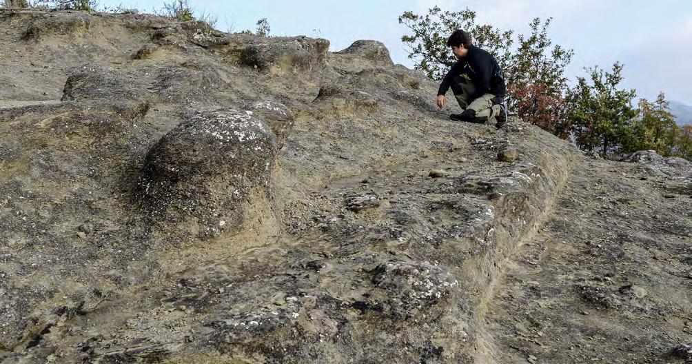
Structureless graded division
Parallel laminae deformed by water escape
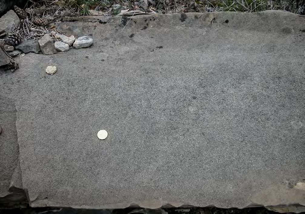
II: Turbidites
SYSTEMS:
OUTCROP-BASED ANALYSIS 207
CHAPTER
TURBIDITE
AN
Fig. 189 - Typical F2-2 beds with structureless graded basal division overlain by thick parallel laminae with water escape features. Oligocene Mioglia system, Tertiary Piedmont Basin.
Fig. 190 - Structureless, slightly graded sandstone bed (F2-2) capped by a thin ripple division. Note shallow scour at the base (indicated by arrow). Eocene Hecho Group, south-central Pyrenees.
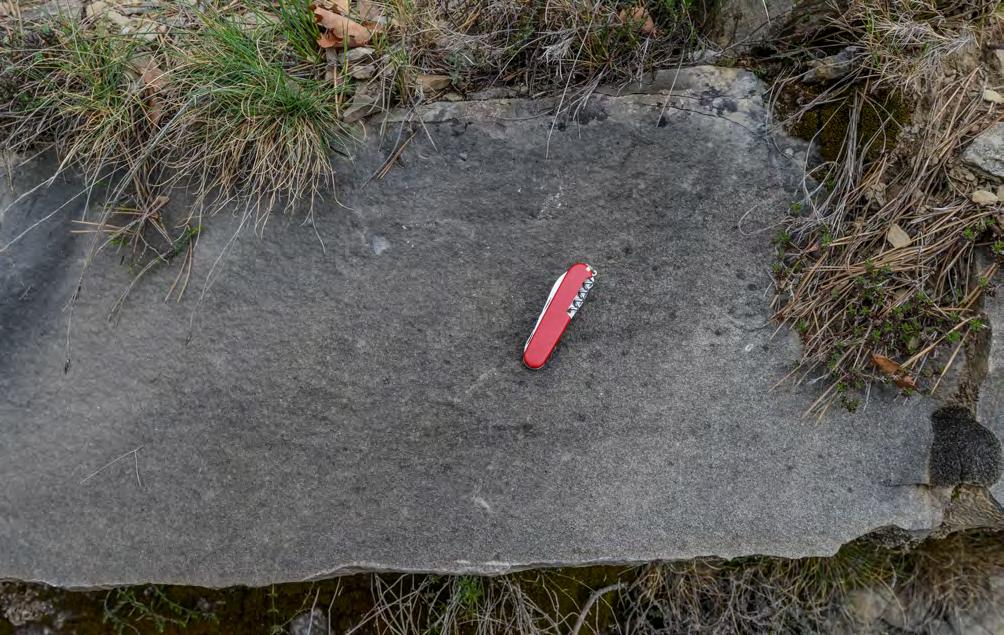
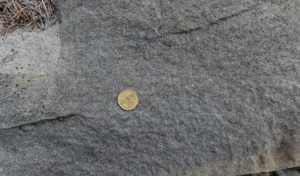
CHAPTER II: Turbidites TURBIDITE SYSTEMS: AN OUTCROP-BASED ANALYSIS 208
Fig. 191 - Structureless sandstone bed (F2-2). Eocene Hecho Group, south-central Pyrenees.
Fig. 192 - Close-up of the bed of Figure 191 showing the total lack of internal stratification in the basal structureless division.
Bypass surface
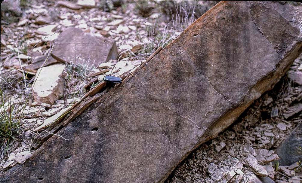
Structureless division
Floating shale clast
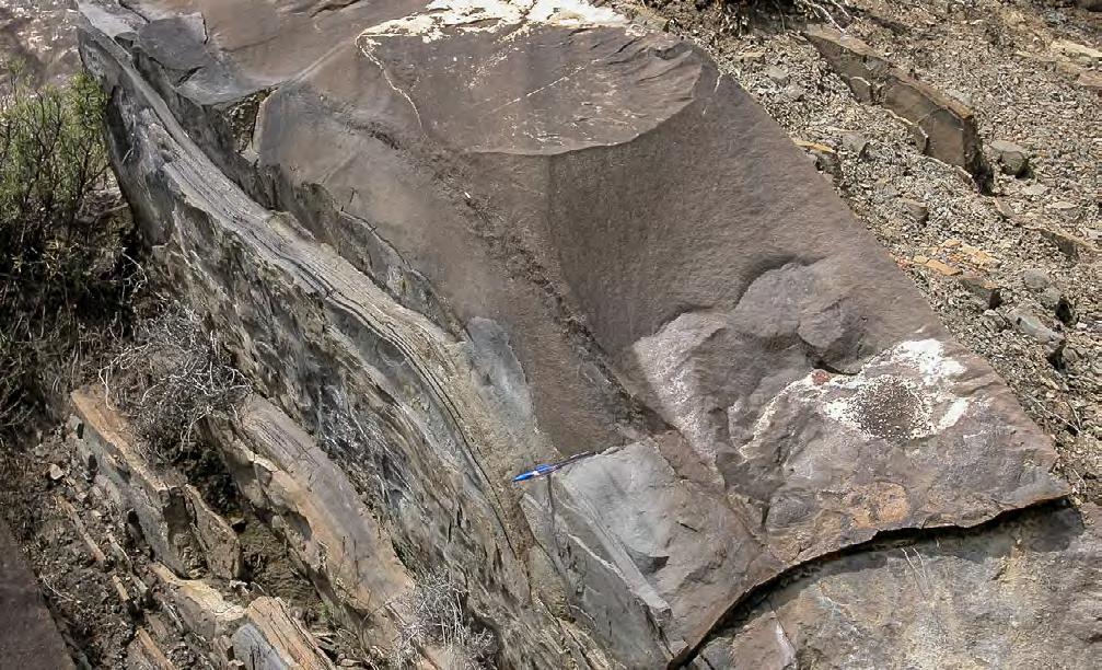
Grain-size break and bypass surface
CHAPTER II: Turbidites TURBIDITE SYSTEMS: AN OUTCROP-BASED ANALYSIS 209
Fig. 193 - Structureless bed (F2-2) with floating shale clasts up to the boundary with an upper laminated division, suggesting that the boundary separates a dense-flow deposit (below) from a dilute-flow deposit (above). Eocene Hecho Group, south-central Pyrenees.
Fig. 194 - Typical F2-2 bed showing a basal structureless division (sld), followed by a bypass surface in turn overlain by a parallel-laminated division (pld) and a ripple-laminated division (rd). Eocene Hecho Group, south-central Pyrenees.
SLD
RD
PLD
Parallel-laminateddivision
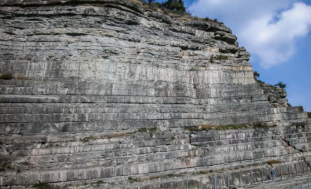
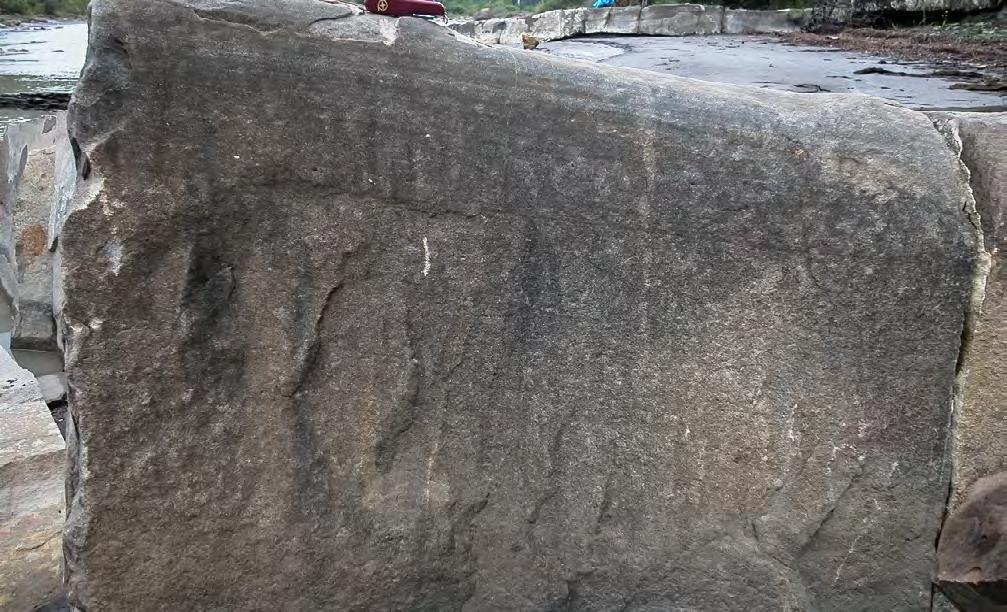
Thick parallel laminae
Structureless division
CHAPTER II: Turbidites TURBIDITE SYSTEMS: AN OUTCROP-BASED ANALYSIS 210
Fig. 195 - Spectacular succession of parallel-sided F2-2 sandstone beds. Miocene Marnoso-arenacea, northern Apennines. Note tabular geometry and the occurrence of thin shaly partings.
Fig. 196 - F2-3 bed, showing a basal structureless division transitionally overlain by thick parallel laminae (traction carpets ?). Eocene Hecho Group, south-central Pyrenees.
Structureless and graded Faint horizontal laminae
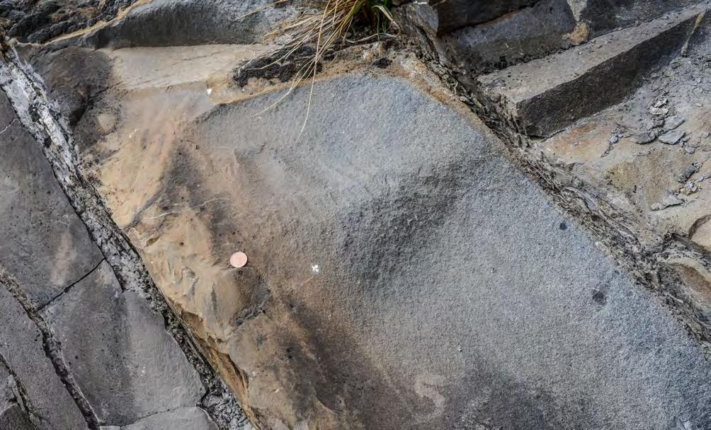
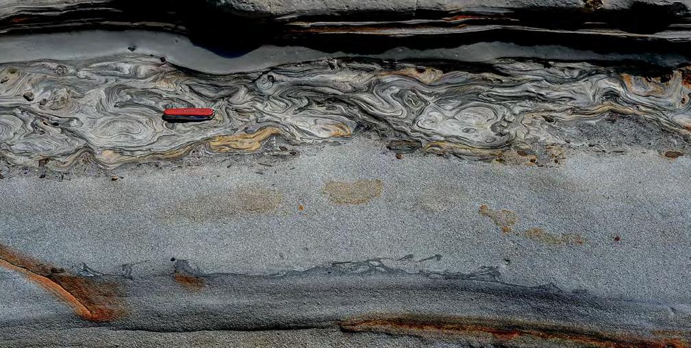
Flame structures
CHAPTER II: Turbidites TURBIDITE SYSTEMS: AN OUTCROP-BASED ANALYSIS 211
Fig. 197 - Graded structureless division overlain by faint parallel laminae (traction carpets from an overlying suspension ?), in turn sharply overlain, through a grain-size break (arrow), by ripple laminae (F2-3).Eocene Broto system, Hecho Group, south-central Pyrenees. Beds are up-side down.
Fig. 198 - A. Medium-grained structureless division with basal load features deposited by a dense sandy flow under conditions of excess pore pressure. Japaratinga, Sergipe-Alagoas Basin, Brazil. Note basal flame structures and diapir-like features at the top of the division with concentration of mudstone clasts and plant fragments floating at the top of the dense flow (red arrows). B. Fine-grained current-laminated division (mostly current ripples) deposited by a dilute turbulent flow and plastically deformed by water escape moving upward and laterally. C. Impervious mudstone division.
Ripple laminae
C B
A
Current-ripple division
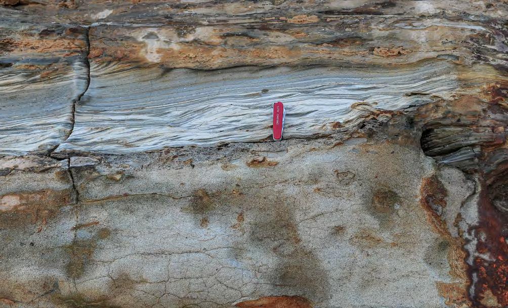
Structureless division
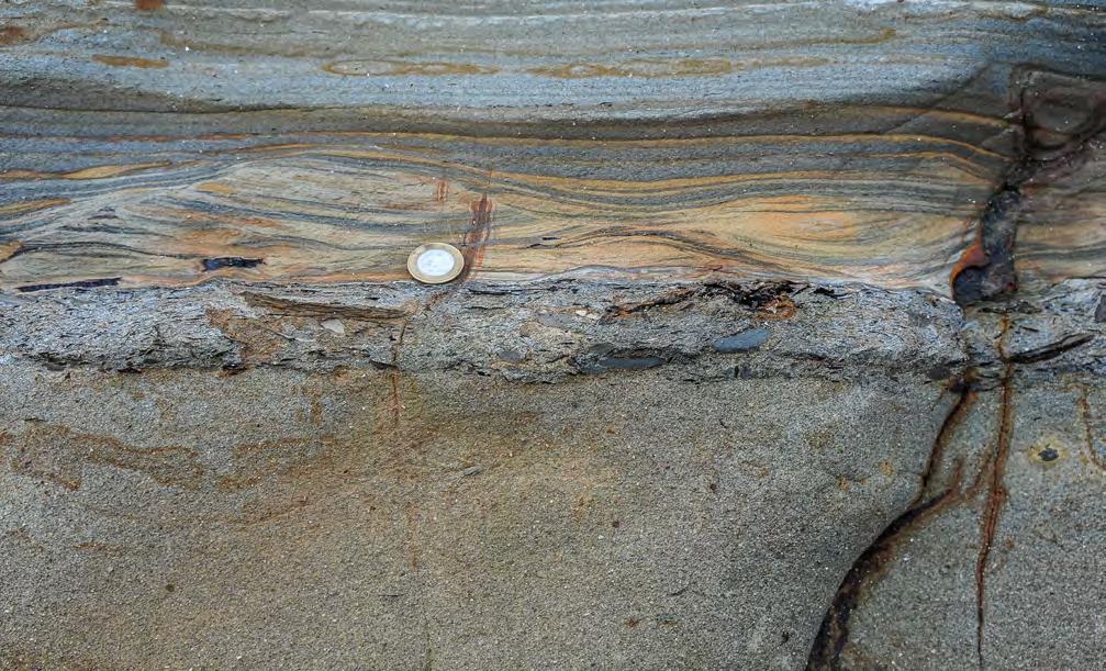
CHAPTER II: Turbidites TURBIDITE SYSTEMS: AN OUTCROP-BASED ANALYSIS 212
Fig. 199 - Example showing dewatering of the dense-flow deposit (structureless division) before deposition of the overlying and undeformed ripple division. Japaratinga, Sergipe-Alagoas Basin, Brazil.
Fig. 200 - Detail of Figure 199 showing floating mudstone clast and plant fragments at the boundary between the dense- and the dilute-flow deposits. Some plant fragments were also incorporated at the base of the dilute flow. Japaratinga, Sergipe-Alagoas Basin, Brazil.
As noted above, the sandy dense flows responsible for the deposition of the bulk of these beds are herein interpreted as supercritical flows. The common occurrence of multiple scours (cut-and-fills) and related traction carpets can be explained by localized and repetive hydraulic jumps associated with chutes and pools or small-scale cyclic steps, probably generated along the upper interface of denser basal layers progressively forming through settling from above layers.
VII. 8.1.4 - F3 and its facies boxes
F3 deposits are basically the same as those of the facies B of Mutti and Ricci Lucchi (1972) who described them as “medium-fine to coarse sandstones, better sorted than sandstones of facies A (F2 of the present paper), in thick to massive beds which are lenticular, however, more laterally continuous than the sandstones of Facies A. These beds are characterized by thick, parallel or broadly undulating current laminae. Shale clasts and erosional features are quite frequent. Dish structures are occasionally present. These sediments are inferred to be the product of both grain flows and high velocity turbidity currents (upper flow regime; particularly the anti-dune phase).” (op.cit., p. 162). The same type of facies, though without an interpretation, was later described as B1 facies by Mutti (1979).
The original description is from the upper part of the Miocene Marnoso-arenacea Formation, northern Apennines, and its interpretation was largely based on a suggestion by G.V. Middleton with whom the authors had visited the best exposures of these sediments. Figure 201 shows the main features of this facies in their original definition. Figures 202-208 show examples of this kind of facies from the same formation and from the Miocene Laga Formation.
A fundamental paper for introducing these turbidite sediments is that of Van Vliet (1982) on the Eocene Guipuzcoa Flysch in the Basque region, northern Spain. In this paper (see also Kruit et al., 1975, and Van Vliet, 1978), the author describes the stratigraphy of this spectacularly exposed turbidite succession through a series of detailed logs that focus in particular on par-
allel-laminated sandstone facies with abundant water escape features. These sandstones may occur in isolation or form an internal division of many beds which is underlain by coarser-grained, structureless and crudely graded division with multiple scours and is sharply overlain by a single set or a coset of medium-scale cross bedded sandstone (Figure 210). I visited these exposures with Arthur Van Vliet and the late Tor Nilsen in 1974, but I could not perceive their importance, nor their importance was perceived by Van Vliet at that time, when we were mostly concerned with large-scale deep-sea fan architectures. I have revisited some of these exposures recently with Philippe Crumeyrolle, a former student of mine presently at Total, and my attention was captured by the beautiful parallel-laminated sandstones. So, I returned to these outcrops a few months later with Rogerio Cunha and Fabrizio Lima to make more detailed observations. At that point I became convinced that the Facies B of Mutti and Ricci Lucchi (1972) is indeed the deposit of supercritical turbidity currents, and that the interpretation is substantiated by the dune-shaped and cross-stratified sandstone facies that sharply overlay them and record the transition to a subcritical regime (see later).
The sandstones of F3 are characterized by a general good sorting and display a dominant parallel lamination enhanced by thickness and grain-size variations. Careful inspection reveals large-scale wavy laminae, low-angle cross laminae (dipping in both up- and down-current direction), subtle truncation surfaces, wedging, and shallow erosional surfaces generally paved with small shale clasts. Most thin sets of laminae display typical thinning- and fining-upward trends, possibly resulting from the decreasing amplitude of antidune within a train of these bedforms (see Cartigny et al., 2014). Figures 209-218 show some of the characteristics of these sediments.
Most of these features are common to the Guipuzcoa Flysch, the Marnoso-arenacea and the Laga Formation. Based on my personal observations, similar laminated facies, though interpreted in a different way (e.g., Felletti et al., 2009; Marini et al., 2011) or simply described (e.g., Cornamusini, 2004), are also common in many flysch units of the northern Apennines.
CHAPTER II: Turbidites TURBIDITE SYSTEMS: AN OUTCROP-BASED ANALYSIS 213
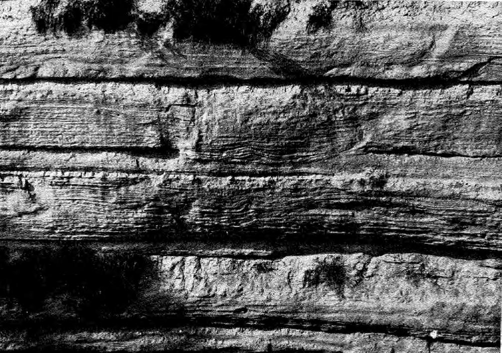
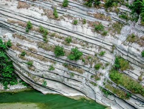
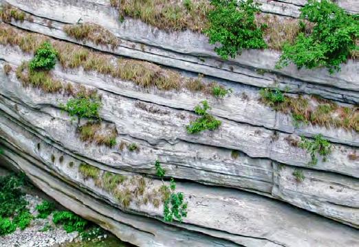
CHAPTER II: Turbidites TURBIDITE SYSTEMS: AN OUTCROP-BASED ANALYSIS 214
Fig. 201 - Medium to fine sandstone beds in parallel-sided beds showing thick parallel, wavy, and low-angle cross laminae, as well as internal scours. Miocene Marnoso-arenacea Formation, northern Apennines. These beds were originally thought to be the deposit of antidunes in supercritical flows (from Mutti and Ricci Lucchi, 1972, their Figure 2, p. 167).
A B
Fig. 202 - Typical exposure of parallel-sided thick sandstone beds of F3. Internal structures mainly include thick horizontal, wavy and low-angle cross laminae. Note large basal scours in B. Miocene Marnoso-arenacea Formation, northern Apennines. Courtesy of Franco Ricci Lucchi.
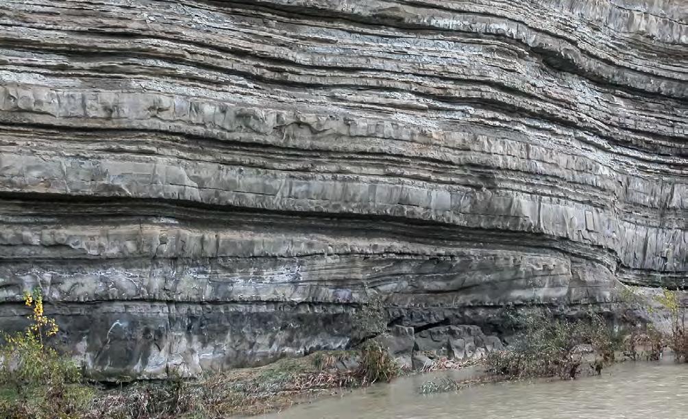
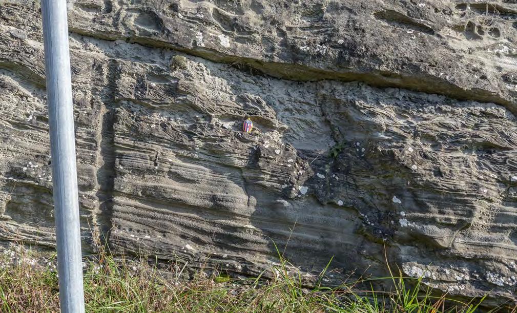
CHAPTER II: Turbidites TURBIDITE SYSTEMS: AN OUTCROP-BASED ANALYSIS 215
Fig. 203 - Bedding pattern of F3 sandstone beds. Note slightly oblique beds in the lower part of the exposure. These beds could be interpreted as backsets associated to a hydraulic jump located farther to the right. Miocene Marnoso-arenacea Formation, northern Apennines.
Fig. 204 - F3 beds. Note thick gently dipping cross laminae and wedge-shaped laminasets. These features are interpreted to be product of supercritical flow, mostly antidunes. Flow is to the right. Miocene Marnoso-arenacea, northern Apennines.
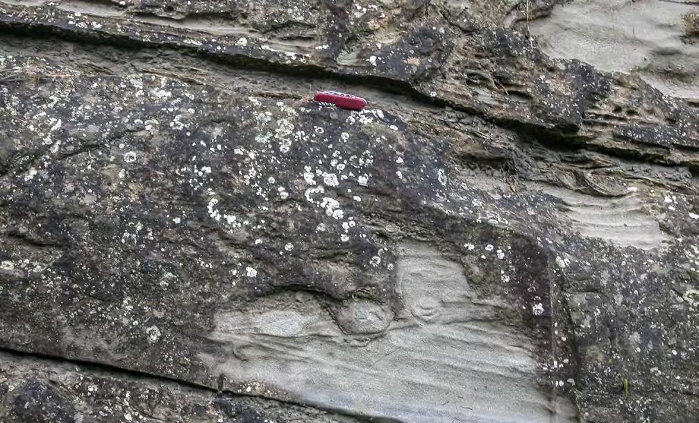
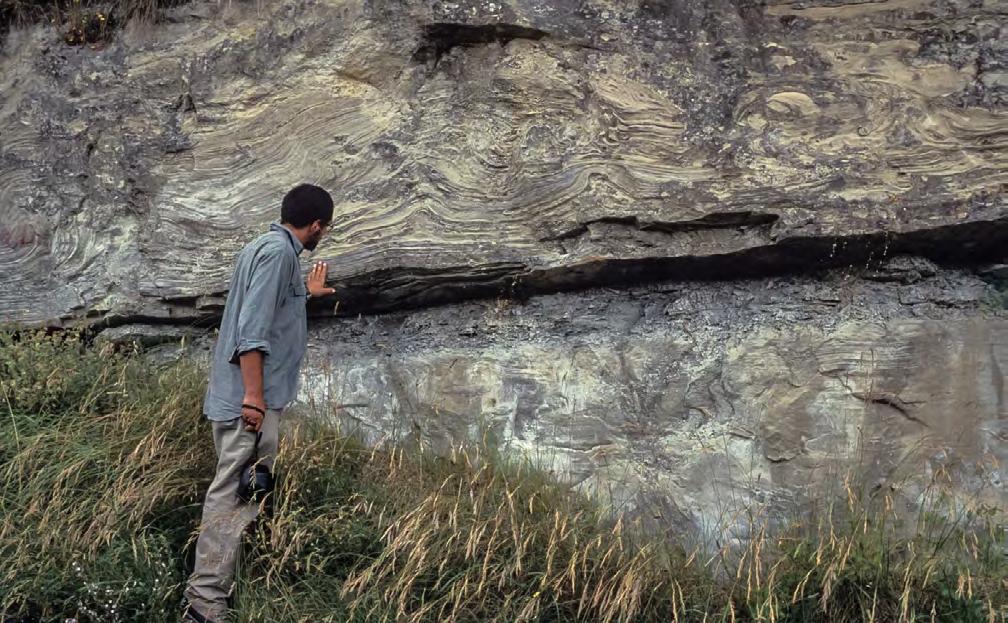
CHAPTER II: Turbidites TURBIDITE SYSTEMS: AN OUTCROP-BASED ANALYSIS 216
Fig. 205 - F3 beds. Truncation surface (internal scour) into a parallel-laminated division. Miocene Marnoso-arenacea, northern Apennines.
Fig. 206- F3 beds showing thick parallel laminae deformed by water escape. Miocene Marnoso-arenacea, northern Apennines.
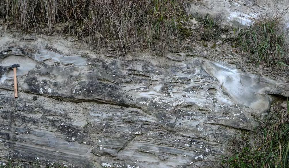
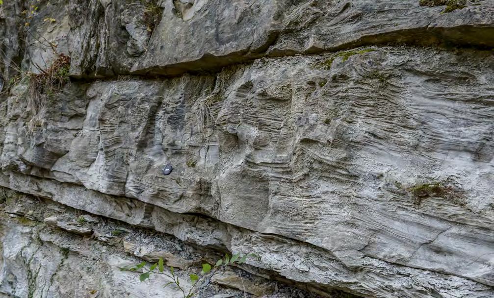
CHAPTER II: Turbidites TURBIDITE SYSTEMS: AN OUTCROP-BASED ANALYSIS 217
Fig. 207 - F3 beds showing basal divisions characterized by supercritical internal structures overlain by climbing-ripple divisions. See text for explanation. Miocene Marnoso-arenacea, northern Apennines.
Fig. 208 - F3 bed showing wavy, low-angle cross laminae and water escape features overlain by a thick division of climbing ripples. Miocene Laga Formation, northern Apennines.
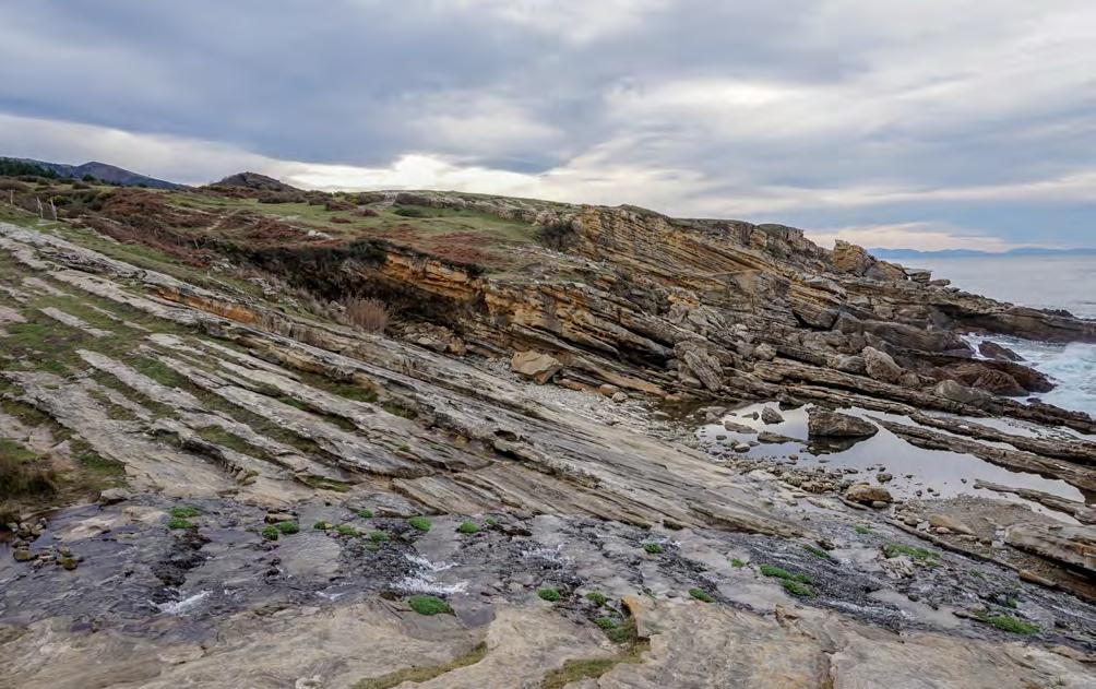
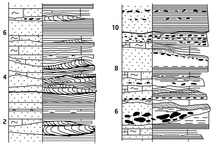
CHAPTER II: Turbidites TURBIDITE SYSTEMS: AN OUTCROP-BASED ANALYSIS 218
Fig. 209 - Spectacular coastal exposure of the early Eocene Guipúzcoa Flysch, northern Spain. The lower part of the local succession is entirely made up of thick, parallel-sided beds of well-sorted sandstone of F3.
Fig. 210 - Detailed logs showing sets and cosets of cross-laminated sandstones scouring into underlying horizontal and/or gently dipping laminae. Cross laminae are locally folded by the drag of bypassing flows. Mudstone clasts occur at the base of scours. Scale in meters to the left. From Van Vliet (1982).
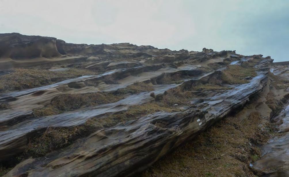
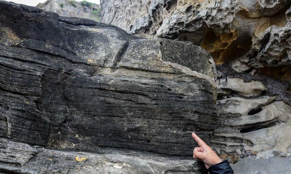
CHAPTER II: Turbidites TURBIDITE SYSTEMS: AN OUTCROP-BASED ANALYSIS 219
Fig. 211 - Thick F3 sandstone beds displaying internal parallel and wavy laminae. Eocene Guipúzcoa Flysch, Basque country, Spain.
Fig. 212 - F3 beds. Subtle truncation surfaces and very low-angle cross laminae. Eocene Guipúzcoa Flysch, Basque country, Spain.
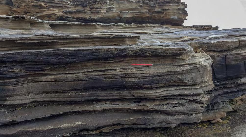
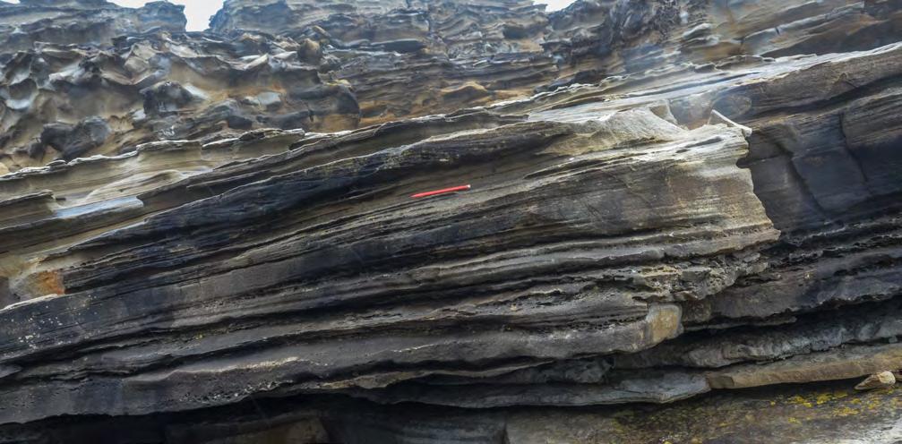
Low-angle cross laminae
Wedging to left
Shale clasts
CHAPTER II: Turbidites TURBIDITE SYSTEMS: AN OUTCROP-BASED ANALYSIS 220
Fig. 213 - F3 beds. Low-angle, sinusoidal cross laminae dipping roughly opposite to main flow direction. Careful observation indicates very subtle pinching-out of several laminasets. Eocene Guipúzcoa Flysch, northern Spain.
Fig. 214 - Detail of Figure 213 showing low-angle cross laminae, wedging of laminasets and shale clasts (F3 facies). Eocene Guipúzcoa Flysch, northern Spain.
Mudstone clast
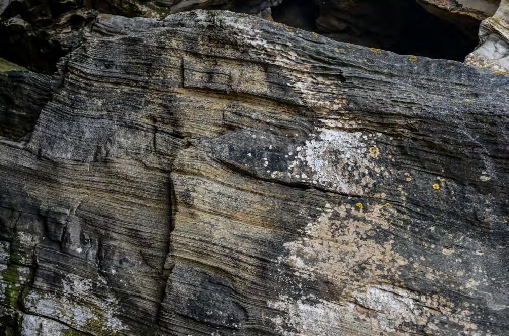
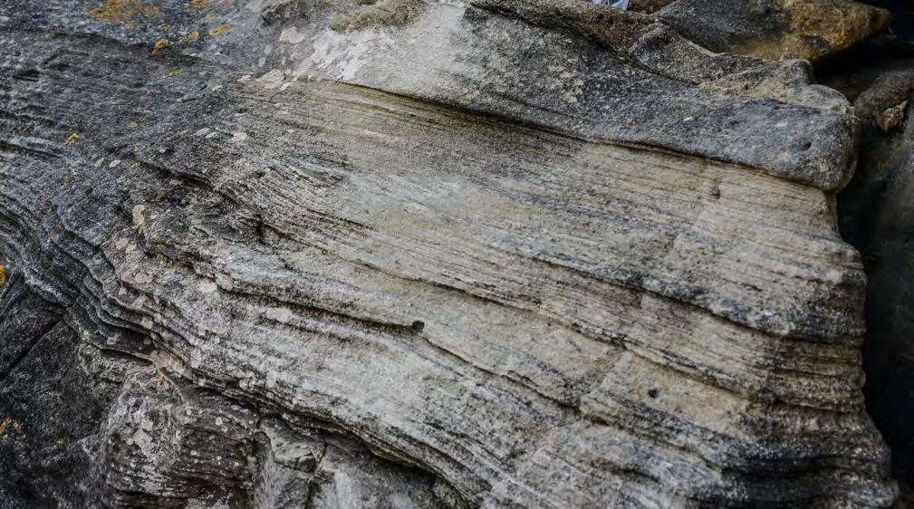
CHAPTER II: Turbidites TURBIDITE SYSTEMS: AN OUTCROP-BASED ANALYSIS 221
Fig. 215 - F3 beds. Examples of small thinning- and fining-upward laminasets produced by antidunes. Eocene Guipúzcoa Flysch, Basque country, Spain.
5 cm
5 cm
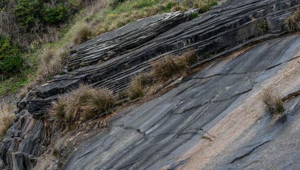
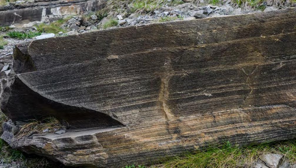
CHAPTER II: Turbidites TURBIDITE SYSTEMS: AN OUTCROP-BASED ANALYSIS 222
Fig. 216 - F3 beds. Division of thick parallel to slightly wavy laminae. Eocene Guipúzcoa Flysch, northern Spain.
Fig. 217 - F3 parallel-laminated sandstone. Laminasets form very distinctive cm-thick thinning-upward trends possibly produced by decreasing amplitude of antidunes (see text). These thin trends are almost ubiquitous in many parallel-laminated beds, providing a good criterion to distinguish this structure from the b Bouma division. Eocene Guipúzcoa Flysch, northern Spain.
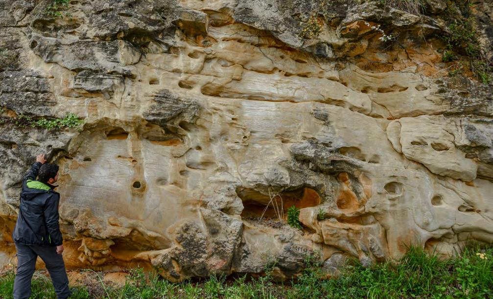
In recent years there has been an increasing interest in flow criticality and attempts have been made to describe sedimentary structures produced by supercritical flows. Attempts are mostly based on small-scale flume experiments, numerical simulations, and theoretical considerations with very limited support from field observations (e.g., Alexander et al., 2001; Cartigny et al., 2014, with references therein; Fedele et al., 2016). The possible importance of these structures in fluvial sediments has been reviewed by Fielding (2006) who suggests that supercritical sedimentary structures might even represent a new architectural element of fluvial strata. From the above studies, the conclusion can be drawn that these structures do exist but have gone unnoticed in most previous outcrop-based studies. On the other hand, their theoretical study seems in its infancy and probably needs a vigourous and hopefully useful input from new and well-constrained field observations to bridge an obvious gap in facies analysis (see final Chapter for additional comments and references).
For the limited purposes of this book, and because of my very limited knowledge of hydrodynamics, it is sufficient to emphasize here that F3 sediments oc-
cupy a relative position within individual sandstone beds which, according to the Walther’s principle, indicates a flow regime higher than that of the overlying cross-bedded sandstones (F4) deposited by a subcritical flow (see later). A second important point is that these facies are quite unique and therefore easy to recognize, though their interpretation remains extremely difficult at present. The fact that they have gone unnoticed is entirely due to our preconceived ideas when looking at the rocks.
For the reasons above, facies boxes illustrating this facies are only meant to show some examples of this kind of turbidite sedimentation basically without interpretation. Much work remains to be done on these sediments.
VII. 8.1.5 – F4 and its facies boxes
This group consists of very distinctive sandstone beds basically formed by migrating dunes (mostly 3D megaripples) and associated coarse-grained ripples; migrating dunes form broadly lenticular beds that can
CHAPTER II: Turbidites TURBIDITE SYSTEMS: AN OUTCROP-BASED ANALYSIS 223
Fig. 218 - Thick, graded and amalgamated sandstone beds (F3) displaying parallel laminae and water escape structures (lower part of the exposure). Eocene Guipúzcoa Flysch, Basque country, Spain. Note the excellent reservoir characteristics.
easily recognized in outcrop studies. Dune geometry and internal cross laminae consistently indicate flow direction coincident with that of sole markings. Sandstone dunes most commonly vary in height between 5-20 cm and in length from 1.5 to 3 meters.
Recognized in early work by several authors (e.g., Hubert, 1966; Watson, 1981), these beds were first described in detail by Mutti (1977) who intuitively interpreted them as the product of sudden flow expansion and deceleration taking place at channel exits followed by fallout of the coarsest particles and their traction along the bed with bypass of the residual flow, i.e., a process basically similar to a hydraulic jump. The interpretation was strengthened in subsequent work by Mutti (1979) and particularly by Mutti and Normark (1987, 1991). The latter authors highlighted the importance of the hydraulic jump and interpreted these beds as a typical expression of their “channel-lobe transition zone”, a zone of crucial flow transformation in both poorly- and highly efficient deep-sea fans and turbidite systems (see above). More recently, these beds have been briefly discussed also by Sumner et al. (2012), though with poorly documented examples from the Marnoso-arenacea Formation.
As shown in Figures 219-237, F4 deposits display a variety of facies boxes. F4-1 consists of medium- to largescale cross strata of coarse to very coarse grained sandstone with repeated erosional contacts, probably indicating composite beds from successive flows. Mudstone clasts (not shown) may be common. F4-2 (Figure 231) is made of dune-shaped beds of medium to coarse grained sandstone, which may locally contain granules, small pebbles and mudstone clasts. Beds are highly lenticular, bounded by sharp contacts below and above and characterized by internal cross laminae that can either be well or crudely developed and conform the leeside of the megaripple. F4-3 (Figures 221-223) consists of rippled coarse-grained sandstone in thin to very thin and highly lenticular and irregular beds, with eight and length varying over very short distance. Beds are sharp based and can be directly overlain by a mudstone layer or, through a very distinctive break in grain size, by a thin division of very fine sandstone and siltstone with low-amplitude ripples or sinusoidal laminae passing upward into mudstone. F4-3 beds are laterally transitional to dune-shaped F4-2 beds over very short distance (Figure 224) in both dowcurrent and upcurrent direction suggesting variations in flow velocity over the same distance. Some thin beds form
the infilling of troughs of underlying megaripple bedforms.
F4-4 (Figures 225-226) is characterized by a well-developed basal megaripple-shaped division with troughs sharply overlain by a division of very finegrained sandstone with ripple and sinusoidal laminae, less commonly parallel laminae. Beds of this type are characteristically developed as individual sharp-based units which stand out mainly because of their geometry contrasting with the generally parallel-sided beds of the associated turbidite beds.
F4-5 and F4-6 are also included in this facies group, though with some substantial differences with respect to the facies above. F4-5 (Figures 227-228) are cross-bedded, and relatively coarse-grained sandstone divisions still produced by migrating dunes that occur above structureless, coarse-grained and poorly-sorted sandstone divisions of F2. The basal contact of the cross-bedded division is generally sharp and erosive. F4-6 (Figures 229-231) is found in the upper portion of many F3 beds and differs substantially from the facies described above in that it consists of very well-sorted medium to fine sandstone forming either a single set of dune-shaped dunes or being arranged into climbing-dune sets (Figure 232). The basal contact of these units with the underlying horizontal laminae of F3 divisions is sharp and locally erosive and may contain pockets of coarser grains and small mudstone clasts.
A final type of deposit (F4-7) refers to beds showing a basal structureless division of variable thickness, but commonly less that 0.5 m, overlain, through a sharp or slightly transitional surface, by laminated divisions which record a phase of partial erosion and resuspension of the frozen structureless division from bypassing flows. Parallel laminae of the b Bouma division, which are caracteristically made of very fine sand, contain in this case some coarse-sand grains resuspended from the top of the newly frozen structureless division and forming laminae a few-grain thick. Except for the interpretation, this facies roughly coincides with the near-bed suspension deposits of the F7 of Mutti et al. (2003). The facies is included in F4 because is strictly related to the facies above, being the result of resuspension and local reworking of dense-flow deposits and even of resuspension of sand grains deposited during the main phase of flow decoupling and sand dune or megaripple migration.
CHAPTER II: Turbidites TURBIDITE SYSTEMS: AN OUTCROP-BASED ANALYSIS 224
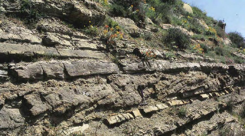
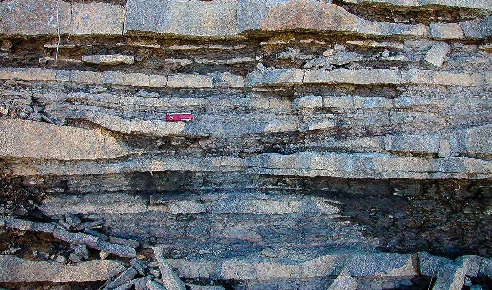
CHAPTER II: Turbidites TURBIDITE SYSTEMS: AN OUTCROP-BASED ANALYSIS 225
Fig. 219 - Very coarse-grained cross laminated sandstone recording multiple phases of megaripple migration (F4-1). Oligocene Reitano Flysch, Sicily, Italy (from Mutti, 1992).
Fig. 220 - Dune-shaped beds of medium to coarse grained sandstone (F4-2) bounded by sharp upper contacts and alternating with thin and highly lenticular sandstone beds (F4-3).
F6
F4-2
F4-2
F4-3
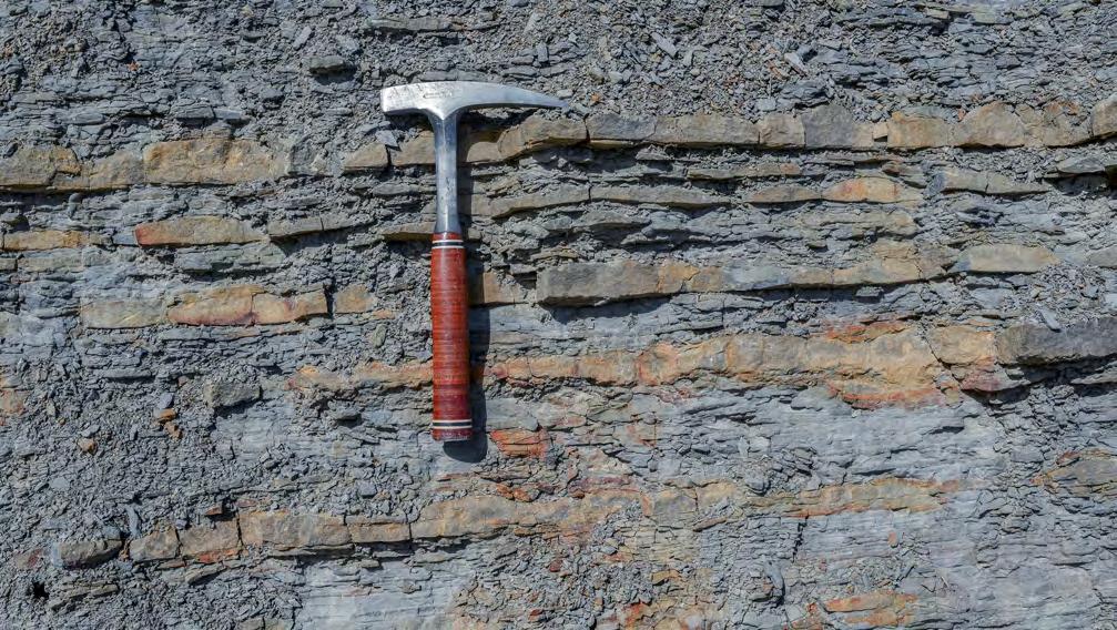
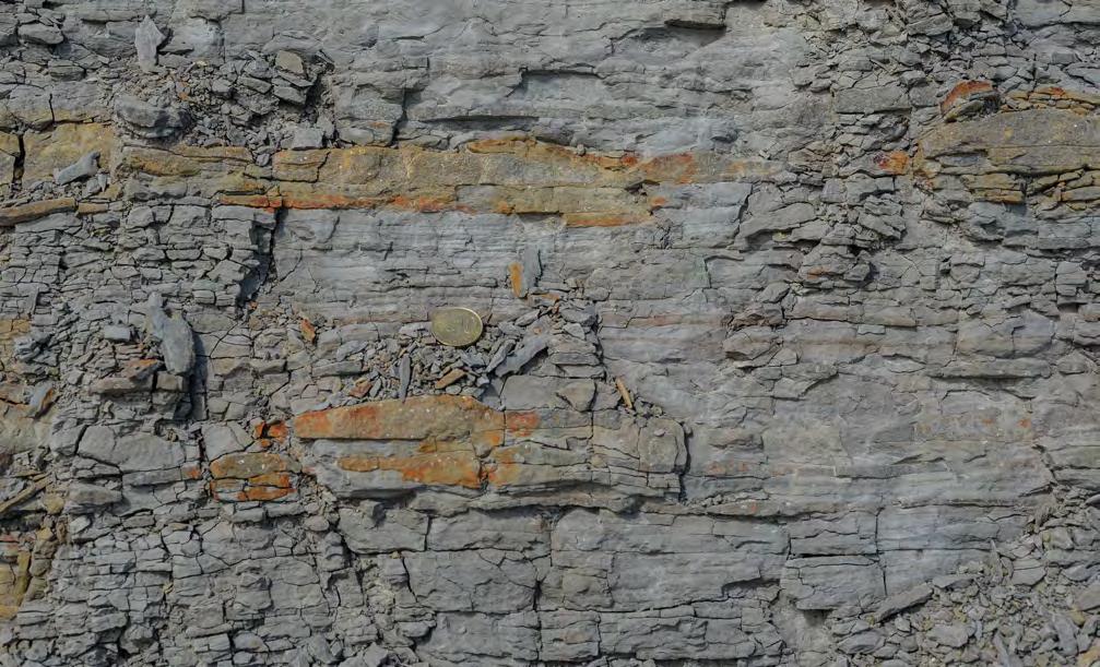
CHAPTER II: Turbidites TURBIDITE SYSTEMS: AN OUTCROP-BASED ANALYSIS 226
Fig. 221 - Typical coarse-grained F4-3 showing variation in ripple height and length over very short distance. Eocene Hecho Group, near Ainsa, south-central Pyrenees.
Fig. 222 - Same as in Figure 221. Coarse-grained and irregularly-shaped F4-3 beds indicated by arrow.
Grain-size break indicating bypass
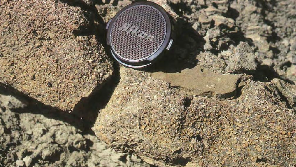
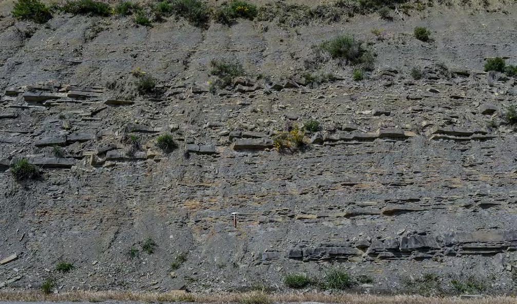
CHAPTER II: Turbidites TURBIDITE SYSTEMS: AN OUTCROP-BASED ANALYSIS 227
Fig. 223 - Thin F4-3 bed of coarse-grained sandstone bounded by sharp contacts below and above. Note the siltstone laminae above indicating bypass. Except for an irregularly rippled upper surface the bed is virtually structureless and ungraded. Eocene Hecho Group, south-central Pyrenees.
Fig. 224 - F4-3 thin beds and their lateral transition (arrow) to thicker F4-2, broadly lenticular beds. Eocene Hecho Group, south-central Pyrenees.
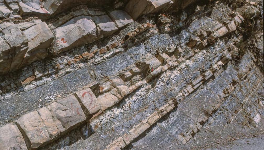
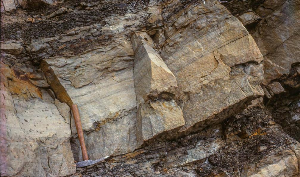
CHAPTER II: Turbidites TURBIDITE SYSTEMS: AN OUTCROP-BASED ANALYSIS 228
Fig. 225 - F4-4 beds. Bed 1 shows a well-developed megaripple at the base. The trough of the megaripple is filled with finer-grained laminated divisions (see Figure 226). Bed 2 shows the same basic motif. Late Eocene Annot Sandstone, Maritime Alps.
Fig. 226 - Detail of Bed 2 (Figure 225) in the megaripple trough. Fine-grained parallel and ripple laminated divisions overlie trough a grain-size break the coarse-grained sandstone of the underlying megaripple. The contact is paved with small mudstone clasts.
BED 1
BED 2
Ripple laminae
Shale clasts
Parallel laminae
Structureless coarse grained sandstone
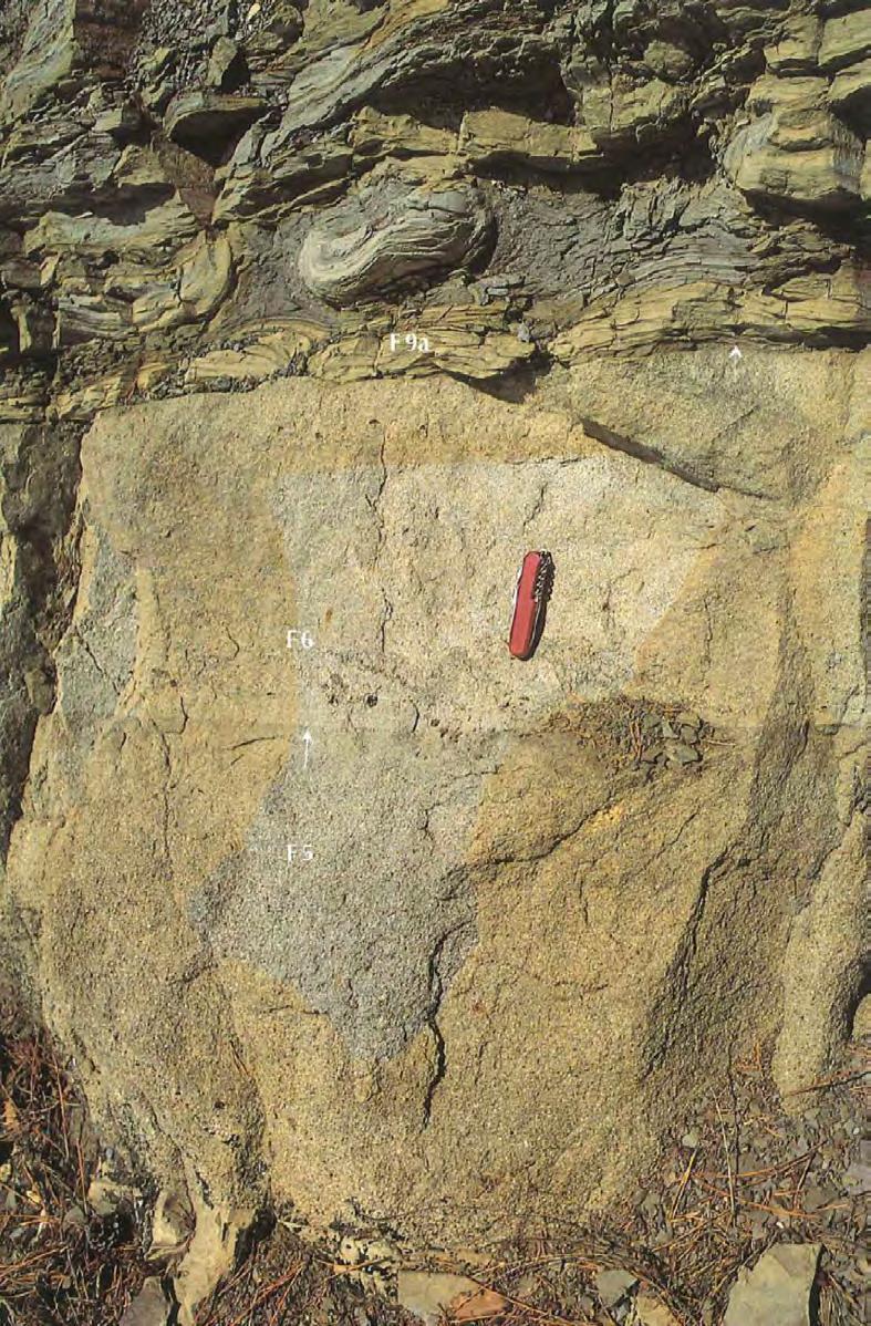
CHAPTER II: Turbidites TURBIDITE SYSTEMS: AN OUTCROP-BASED ANALYSIS 229
Fig. 227 - Cross-laminated sandstone (F4-5) sharply overlying a coarse-grained structureless division (F2). Late Eocene Annot Sandstone, Maritime Alps, France (from Mutti, 1992).
F9a
F6
F5
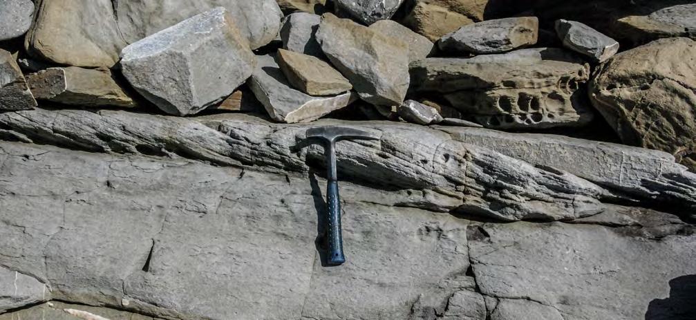
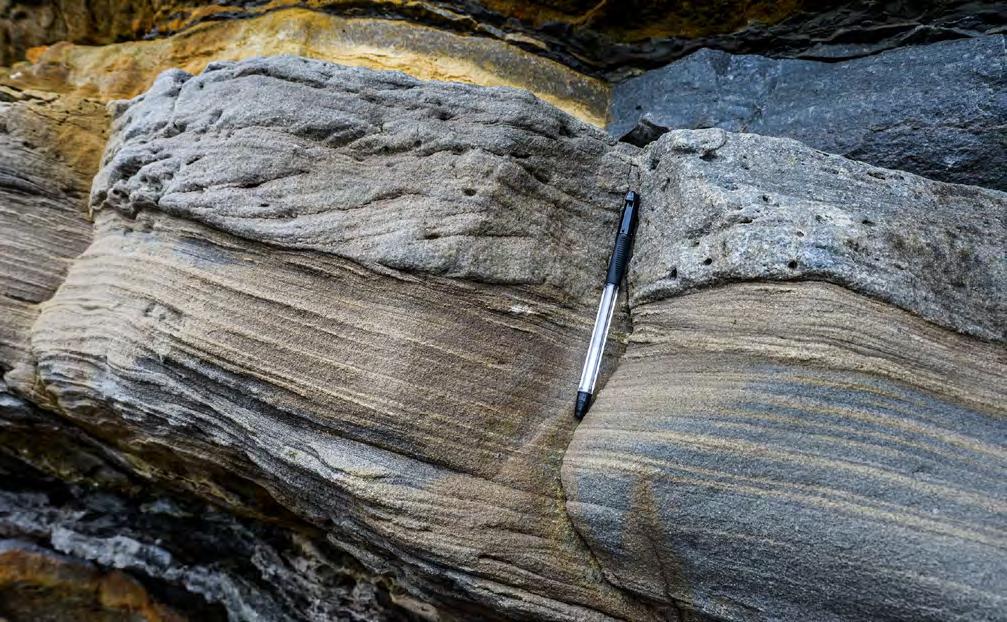
Cross-bedded sandstone
Low-angle cross laminated sandstone with grain-size banding
CHAPTER II: Turbidites TURBIDITE SYSTEMS: AN OUTCROP-BASED ANALYSIS 230
Fig. 228 - Cross laminated sandstone (F4-5) resting through a sligthly erosional contact on a structureless division. Oligocene “Macigno costiero”, northern Apennines. Courtesy of Gianluca Cornamusini.
Fig. 229 - F4-6 bed showing cross bedded sandstone produced by dune migration erosively overlying supercritical very low-angle cross laminae (antidunes). Eocene Guipuzcoa Flysch, northern Spain.
F4-6
Medium-scale cross laminae
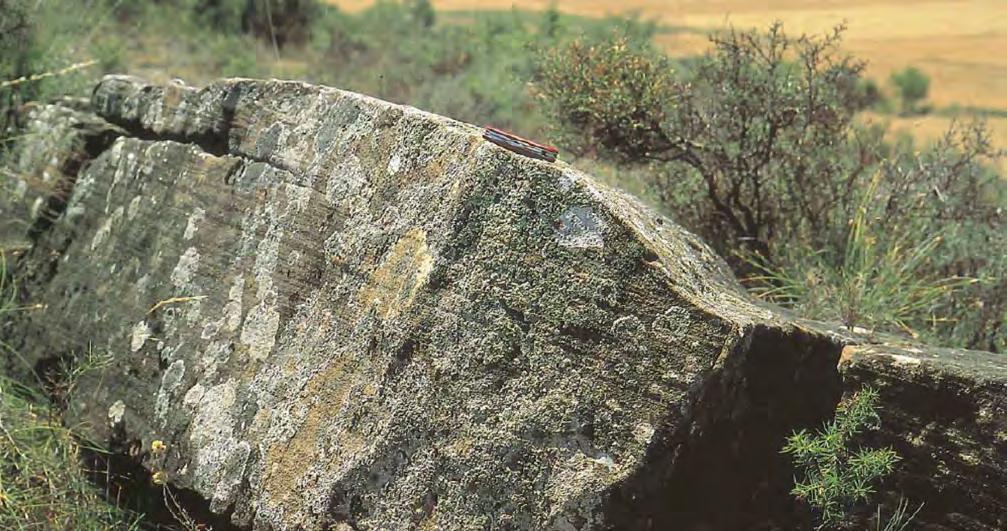
Lee face of megaripple
Parallel laminae
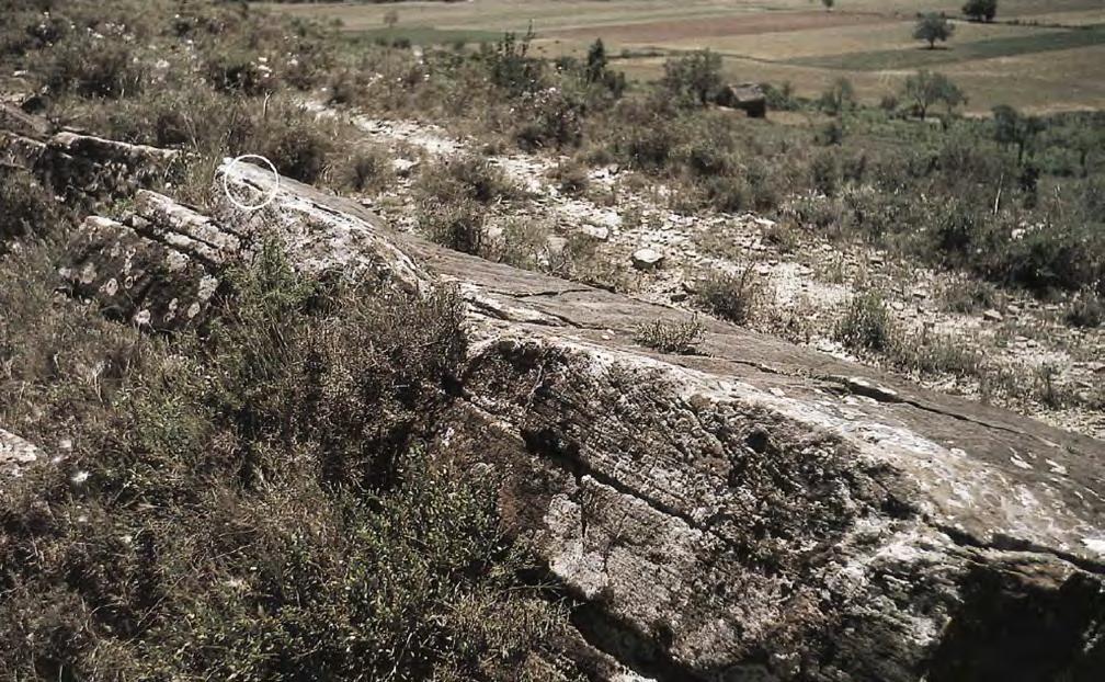
Ripples
CHAPTER II: Turbidites TURBIDITE SYSTEMS: AN OUTCROP-BASED ANALYSIS 231
Fig. 230 - Typical expression of dune-shaped cross-laminated sandstone (F4-6). Eocene Hecho Group, near Ainsa, south-central Pyrenees. A set of cross laminae erosively overlies a division of antidune parallel laminae (modified after Mutti, 1992).
Fig. 231 - Same as Figure 230 showing ripples on top. The crests of these ripple commonly indicate current directions at an angle to the underlying dunes (up to 90°), suggesting very shallow flows (flow tails) controlled by the relief of underlying dunes (modified after Mutti, 1992).
F4-6
F3
F3
F4
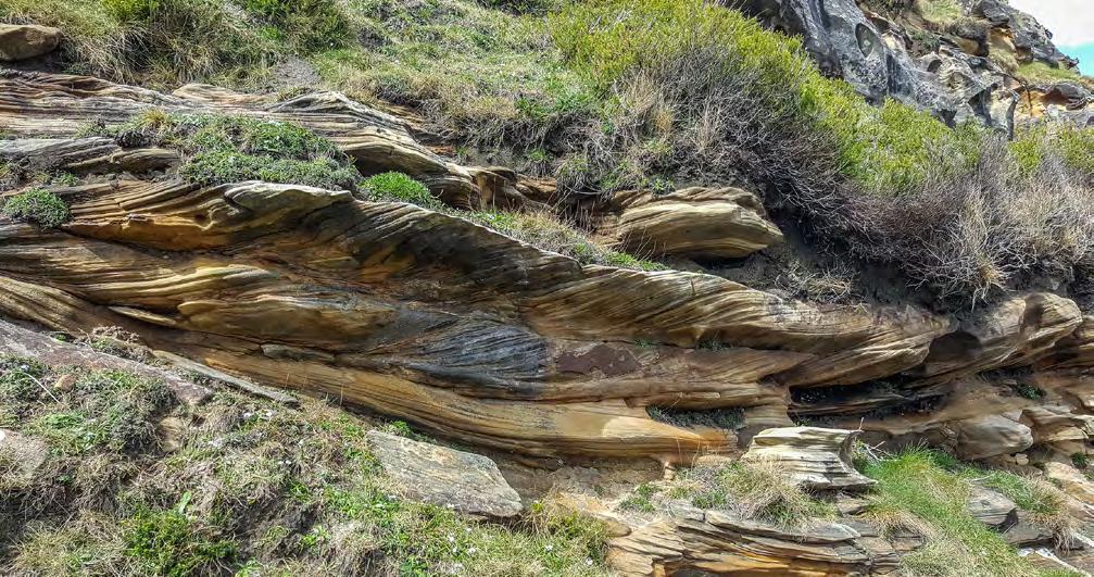
Erosional surface
Parallel laminae
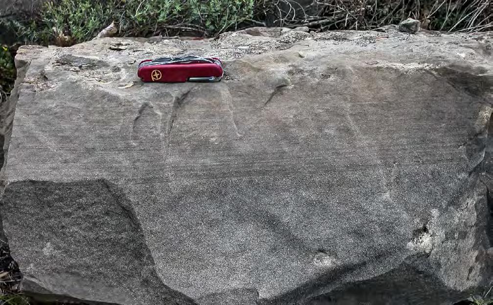
Structureless
Ripple laminae
F4-7
CHAPTER II: Turbidites TURBIDITE SYSTEMS: AN OUTCROP-BASED ANALYSIS 232
Fig. 232 - Sets of climbing dunes (F4-6) erosionally resting upon parallel-laminated sandstone (F3). Eocene Guipuzcoa Flysch, northern Spain. Courtesy of Philippe Crumeyrolle.
Fig. 233 - Basal structureless division sharply overlain by finer-grained thin, parallel laminae. The lowermost laminae contain alignments of medium and coarse sand resuspended from the underlying structureless division. Eocene Banastòn system, south-central Pyrenees.
Structureless
Ripple laminae
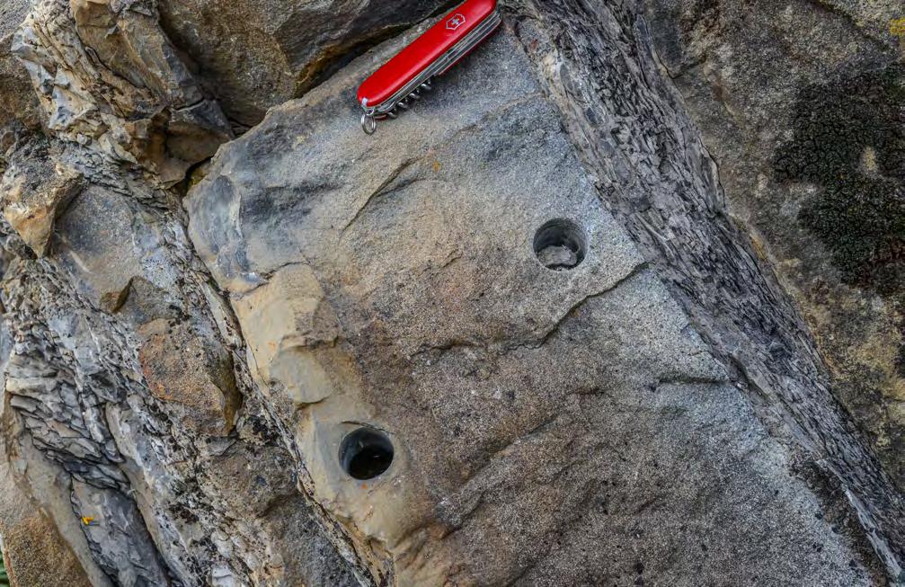
Grain-size break indicating bypass
Parallel laminae with grain-size banding
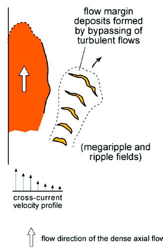
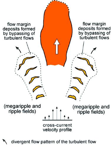
Eocene-Oligocene Ranzano
megaripples on channel terraces of Watson, 1981;
CHAPTER II: Turbidites TURBIDITE SYSTEMS: AN OUTCROP-BASED ANALYSIS 233
Fig. 234 - F4-7 bed showing parallel laminae partially derived from the erosion of an underlying structureless division as suggested by the occurrence of grain-size banding. Eocene Hecho Group, south-central Pyrenees. The bed is upside down.
A B
Fig. 235 - undergoing thinning, dewatering and freezing in trying to ascend a confining slope. A decoupled turbulent flow, which can partly ascend the slope, reworks the frozen dense-flow deposit in megaripple and ripple fields of coarse-grained sediment (F4 beds). The model makes reference to the Eocene Ainsa system (south-central Pyrenees) and the late
Sandstone (northern Apennines). The model may also apply to flows confined in a channel (see
see also Figure 236).
F4-7
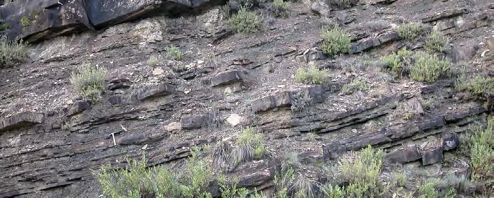
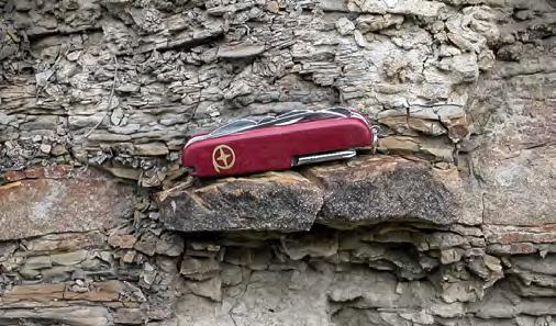
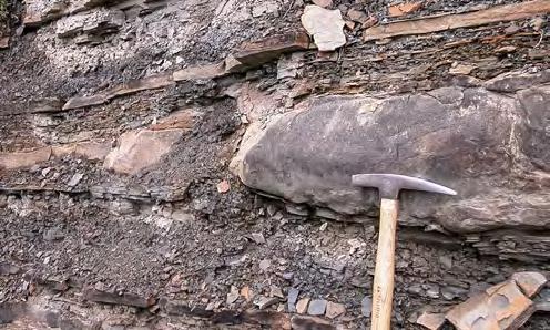
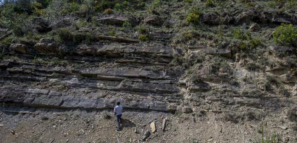
CHAPTER II: Turbidites TURBIDITE SYSTEMS: AN OUTCROP-BASED ANALYSIS 234
Fig. 236 - Lateral facies change from F2 bed (right) to F4-3 bed (thin rippled bed of coarse-grained sandstone) over very short distance. Flow direction is away from the viewer. Small channelized bed within a major erosional unit. Eocene Gerbé-Cotefablo system, Hecho Group, south-central Pyrenees.
F2
Fig. 237 - Example of cross-current flow decoupling from a dense flow (F2) into a bypassing turbulent flow with reworking into F4-3 thin beds (see text for more details). Eocene Hecho Group, south-central Pyrenees.
F4-3
F4 deposits raise several problems as to their origin and significance in turbidite facies analysis. Whatever their interpretation, two basic points have to be kept in mind: first, these sediments have to be considered as an important component of the turbidite family, though underestimated in previous work; secondly, they are clearly produced by migrating dunes and ripples in a subcritical flow moving in a direction concident with that obtained from basal sole markings.
The characteristics of F4 deposits reasonably suggest that sandstone beds are deposited by predominantly tractional processes acting on a coarse-grained sand bed. Depending upon the duration, strength and steadiness of the flow, these deposits vary between relatively well-sorted sandstone beds with well developed cross laminae to poorly sorted sandstone beds with more crudely developed cross laminae and duneand ripple-shaped external geometry.
Based on our field observations, beds of this type occur primarily where dense sandy flows are more or less abruptly decelerated against bounding slopes and bypassed and reworked into tractional bedforms by the residual turbulent flow, essentially a flow splitting, or decoupling dictated by an upslope deceleration and deflection of the dense flow (Figure 235). This model, introduced by Mutti and Tinterri (2004) based on observations carried out in the Eocene of the south-central Pyrenees and in the Eocene-Early Oligocene of the northern Apennines, implies that axial dense sandy flows pinch-out laterally trying to ascend channel margins or gentle slopes created by structural deformation. The model also applies in the case of thick sand beds in proximal lobe regions. In the latter case, these beds are associated with the development of compensation processes (see above). Detailed studies on cross-current facies tracts of slope-ascending flows substantiate the model above (e.g., Tinterri and Tagliaferri, 2015: Cunha et al., 2017). Small-scale examples of flow-decoupling and bypass in a cross-current direction are shown in Figures 236 and 237. As suggested in previous work (Mutti, 1992; Mutti et al., 1999; 2003) and though in a more subtle and gradual way, flow splitting and bypass take place also in a general downflow direction probably partly controlled by compensation and flow decoupling upon low relief lobes, or more simply where the dense flow freezes and its deposit undergoes reworking by the residual and bypassing turbulent flow. The problem needs further in-
vestigations and should imply a better knowledge on flow criticality (see also conclusions in Part 3).
F4-6 is probably the facies of the group of easiest interpretation. The cross-bedded sandstone dunes overlie the horizontally laminated sandstones of F3 which have been interpreted as produced by supercritical antidune aggradation (see above). There seems to be little doubt that this is an example of a vertical transition between a supercritical flow deposit into a subcritical one. As noted above, the contact may be locally erosive and characterized by small mudstone clasts suggesting scouring produced by intense turbulence at a hydraulic jump.
VII. 8.1.6 – F5 and its facies boxes
Mudstone clast-bearing sandstone beds have long been reported in the literature (e.g., Wood and Smith, 1959; Ricci Lucchi, 1965; Marshalko, 1970). Only recently, however, have these beds received considerable attention from sedimentologists especially for their high mud content controlling their reservoir characteristics.
Mudstone clasts can occur anywhere in turbidite sandstone facies, provided that the flows are sufficiently powerful to erode the soft muddy substratum along which turbidity currents move. For this reason, as noted by Mutti and Normark (1987), rip-up mudstone clasts are common in both channel-fill, channel-lobe-transition and lobe elements (Figure 60). However, it soon became clear that sandstone beds containing rip-up mudstone clasts are particulary common and well organized in lobe elements (Mutti et al., 1978; van Vliet, 1978). In a short paper, Mutti and Nilsen (1981) further elaborate on the significance of these beds and proposed a simple model shown in Figure 238. The model suggests that, after erosion of a mud substratum in outer fan regions, the clasts float within the basal denser portion of the flow and move upward for buoyancy as well as downcurrent. The process is accompanied by progressive disaggregation and rounding of the clasts which become smaller with distance until remnants of the original clasts, if still preserved, accumulate at the boundary between the denser basal flow and the overlying more dilute flow. Basically, the model is based on the density of mudstone clasts which is less than that of the dense flow and greater than that of the dilute turbulent flow.
CHAPTER II: Turbidites TURBIDITE SYSTEMS: AN OUTCROP-BASED ANALYSIS 235
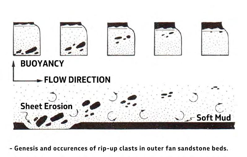
Beginning with Haughton et al. (2003), a great number of papers have dealt with the same problem introducing new important concepts and related terminology (e.g., Talling et al., 2004; Haughton et al., 2009; Magalhaes and Tinterri, 2010; Patacci et al., 2014; Fonnesu et al., 2015, 2018, with references therein). The ideal basic model suggested by Haughton et al. (2009) (Figure 239) describes beds including a basal structureless sandstone (H1), succeeded by a banded sandstone (H2), a muddy sandstone with or without mudstone clasts (H3), a laminated very fine sandstone (H4), and finally a mudstone cap (H5). These beds are referred to as “hybrid event beds” (HEBs) since deposited by similarly “hybrid flows”, i.e., flows with different rheology within the depositing current. Divisions H1 and H4 are interpreted as turbidites, whilst the division H3 is interpreted as a debrite deposited by a cohesive debris flow, being the division H2 (the banded sandstones of Lowe and Guy, 2000) a transitional deposit between the two types of flow. An additional and probably more important division characterizes some of these beds, the “mudstone-clast-rich beds” (MRBs) of Fonnesu et al. (2015, 2018), made up of
mudstone clasts of variable size embedded in a sandy matrix, and thought to be proximal equivalent of HEBs formed in the early stages of hybrid flow development. These beds have long been mentioned in previous literature, though never formalized.
The enrichment in mud of turbidity currents during their motion through bed erosion and their transition to “slurry”, cohesive flows was first documented by Zeng et al. (1991) from the Bute Inlet (see above). Whether this process is of general validity for all turbidite systems remains doubtful; significant bed erosion and development of HEBs seems actually restricted to confined basins and the deceleration and transformations suffered by turbidity currents against confining slopes (e.g., Magalhaes and Tinterri, 2010; Patacci et al., 2014; Cunha et al., 2017). In particular, bed erosion would be enhanced by hydraulic jumps that would increase the pressure above the bed (Postma et al., 2009). It is here suggested that HEBs may also be related to subtle depositional “highs” related to the upbuilding of sandstone lobes in outer fan regions generating hydraulic jumps and flow decoupling.
CHAPTER II: Turbidites TURBIDITE SYSTEMS: AN OUTCROP-BASED ANALYSIS 236
Fig. 238 - Buoyancy and downflow motion of mud clasts (From Mutti and Nilsen, 1981).
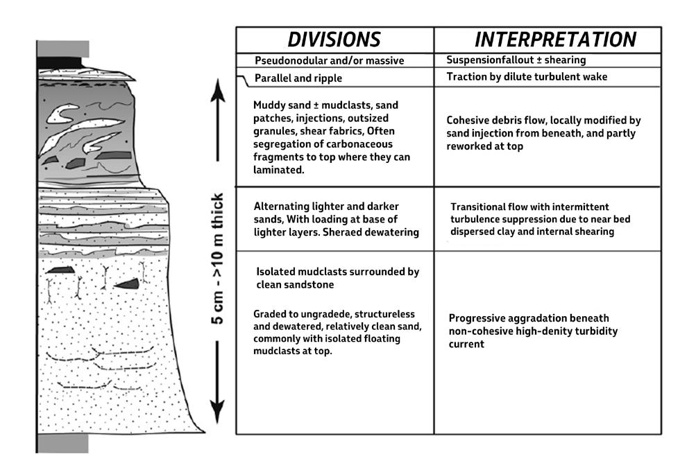
Whatever their origin and significance, HEBs are commonplace in many turbidite systems and their recognition as an important component facies of these systems seems necessary. The best and most simple scheme for their description and interpretation offered until now is that of Fonnesu et al. (2018) which essentially emphasizes the importance of (1) basal sandstone divisions with mudstone clasts and (2) muddy-sandstone divisions (“slurry flow” deposits sensu Ricci Lucchi and Valmori, 1980) sandwiched between sandstone divisions (Figure 240). These two types of occurrences are herein
termed F5-1 and F5-2 respectively. Examples of these facies are shown in Figures 241-249. F5-1 could be further subdivided according to the position of mudstone clasts within each sandstone division. Mudstone clasts may form nests at different levels within the bed, suggesting successive phases of bed erosion. The downcurrent imbrication of relatively flat mudstone clasts may provide in some case an additional tool for establishing flow direction. F5-2 could be further subdivided based on whether the basal sandstone division is structureless (F5-2a) or laminated (F5-2b).
CHAPTER II: Turbidites TURBIDITE SYSTEMS: AN OUTCROP-BASED ANALYSIS 237
Fig. 239 - The model of a hybrid event bed (HEB) according to Haughton et al. (2009). See text.
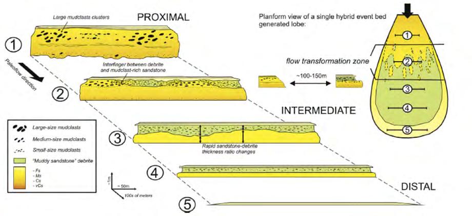
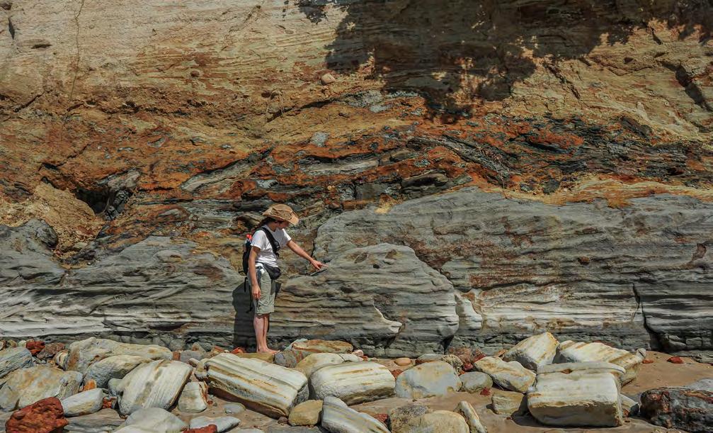
CHAPTER II: Turbidites TURBIDITE SYSTEMS: AN OUTCROP-BASED ANALYSIS 238
Fig. 240 - Diagram showing proximal to distal changes within an ideal depositional cone from mudstone clast-bearing sandstone to a sandwiched muddy sandstone within the same bed. Note the gradual disaggregation of large mudstone clast in a downcurrent direction (from Fonnesu et al., 2015).
Fig. 241 - Large, tabular and angular mudstone clasts contained at the base of a thick, graded and laminated bed (F5-1). The bed scours into an underlying F3 bed with supercritical bedforms. Japaratinga, Sergipe-Alagoas Basin, Brazil.
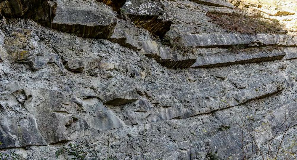
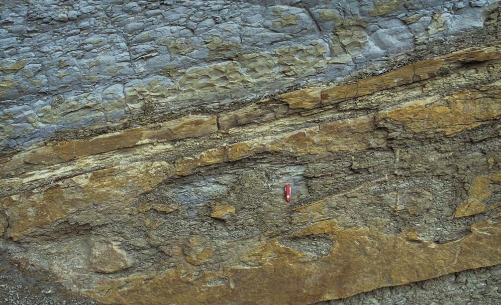
CHAPTER II: Turbidites TURBIDITE SYSTEMS: AN OUTCROP-BASED ANALYSIS 239
Fig. 242 - Structureless sandstone bed (ca 1 m thick) containing m-size clasts of folded and disrupted alternating mudstones and sandstones floating in the upper part of the bed (F5-1). Miocene Marnoso-arenacea Formation, northern Apennines.
Fig. 243 - Sandstone bed containing large mudstone clasts (F5-1). The clasts are floating in a structureless division capped by a set of current ripple. Miocene Marnoso-arenacea, northern Apennines.
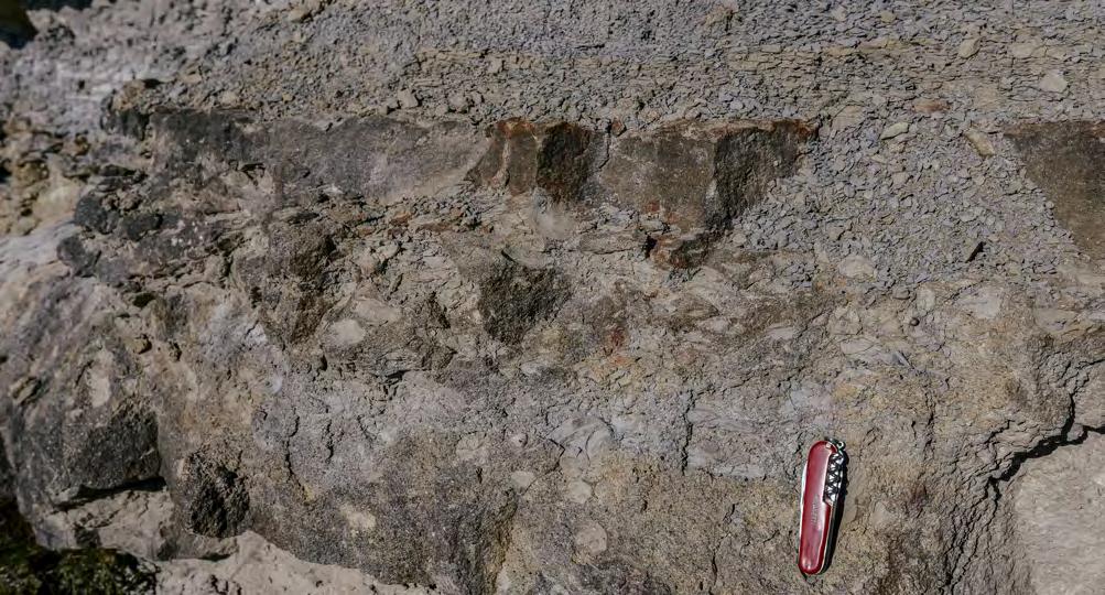
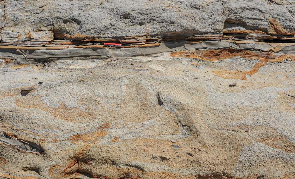
Impervious mudstone division
Remnants of convolute ripple laminae
Upward fluid escape
Structureless division
CHAPTER II: Turbidites TURBIDITE SYSTEMS: AN OUTCROP-BASED ANALYSIS 240
Fig. 244 - Cm-size mudstone clasts floating in a coarse-grained sandy matrix and concentrated in the middle portion of the bed (F5-1). Tertiary Piedmont Basin, northern Italy.
Fig. 245 - Structureless dense-flow deposit showing dewatering features and randomly floating mudstone clasts of various size (F51). The smallest mudstone clasts are concentrated at the top of the structureless division. Japaratinga, Sergipe-Alagoas Basin, Brazil.
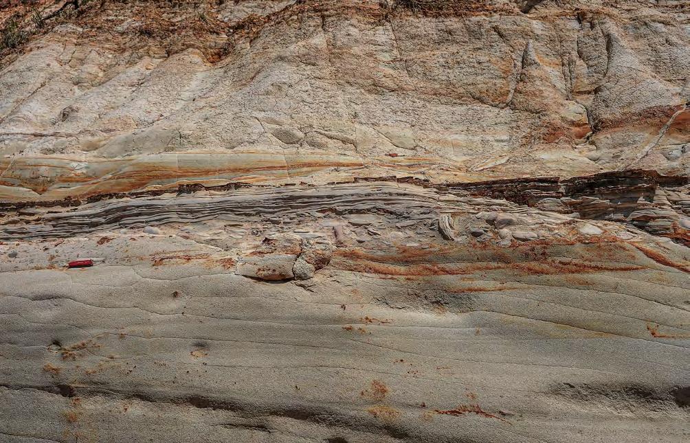
A few personal remarks on these deposits are briefly added below. I would suggest that muddy-sandstone divisions can develop also in absence of large-scale bed erosion (sandstone divisions with mudstone clasts) in cases where diffuse turbulence generates similarly diffuse erosion through flute marks (Figure 250). Large amounts of very small mudstone clasts must be produced by the process and their rapid disaggregation within the flow can certainly promote its transformation into a cohesive flow (“slurry” flow). I also maintain the essentials of the model of Figure 238 implying that rip-up mudstone clasts are first incorporated within a dense flow either through hydraulic jumps (see above), delamination (Fonnesu et al., 2016), or a combination thereof. Buoyancy and downflow motion control the position of these clasts
within the flow and therefore within the bed once frozen. Finally, I would strongly suggest a simpler terminology. Basically, HEBs record a reverse flow transformation (Figure 182) whereby a dense sandy flow becomes a cohesive flow because of progressive ingestion of mud. The flow actually remains the same, despite its local transformation, and the flow and its deposit still remain a turbidity current and a turbidite respectively. If at each flow transformation we change terminology, we add confusion to an inherently complex problem.
For the above reasons, these beds are shown in Figure 150 as being part of the turbidite family and denoted as F5, i.e., “sandstone beds with floating mudstone clasts and/or containing divisions of muddy sandstone”.
CHAPTER II: Turbidites TURBIDITE SYSTEMS: AN OUTCROP-BASED ANALYSIS 241
Fig. 246 - Cm-size mudstone clasts (indicated by arrow) floating at the top of a sandstone division, immediately below a division of finer-grained, current-laminated division (F5-1). Japaratinga, Sergipe-Alagoas Basin, Brazil.
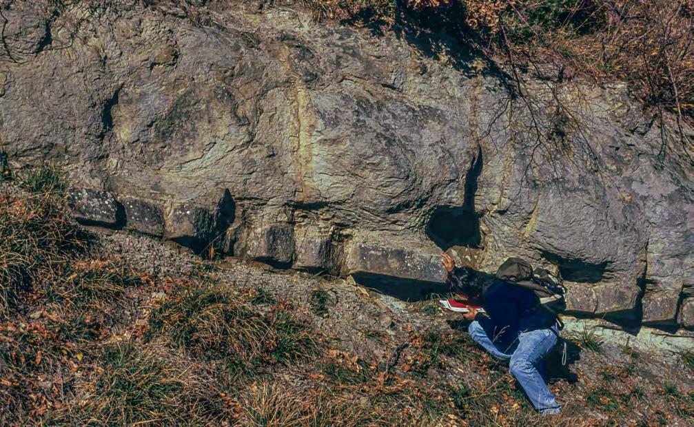
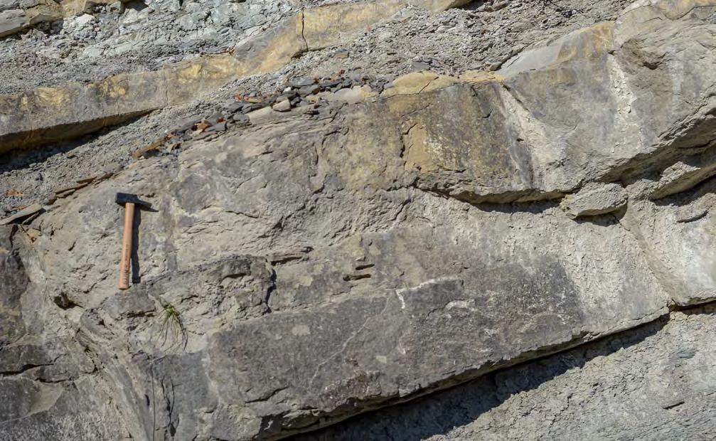
CHAPTER II: Turbidites TURBIDITE SYSTEMS: AN OUTCROP-BASED ANALYSIS 242
Fig. 247 - Examples of muddy sandstone divisions (MSD) underlain by structureless divisions (F5-2a). Miocene Marnoso-arenacea, northern Apennines.
MSD
MSD
Structureless division
Structureless division
MSD
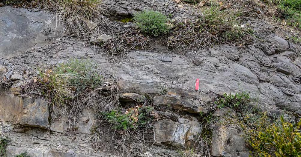
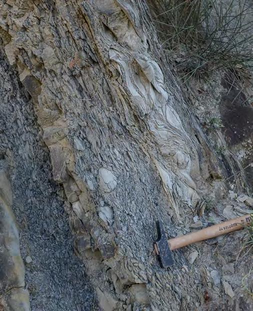
MSD
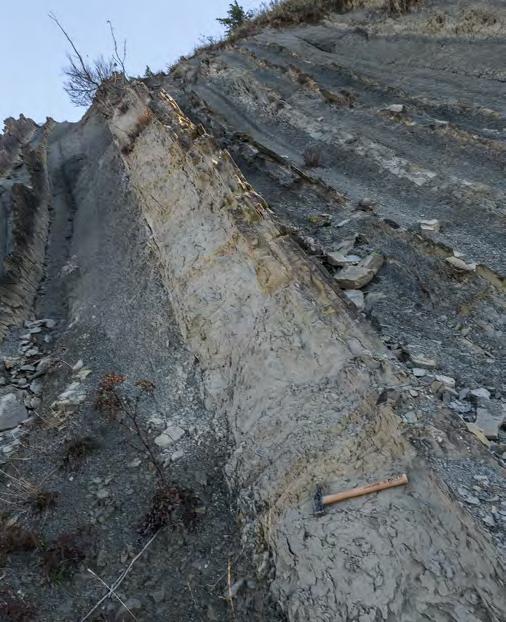
MSD
CHAPTER II: Turbidites TURBIDITE SYSTEMS: AN OUTCROP-BASED ANALYSIS 243
Fig. 248 - Muddy sandstone division (MSD) resting on a sandstone division with thick laminae on top (F5-2b). Eocene Hecho Group, south-central Pyrenees.
Fig. 249 - F5-2b beds showing a muddy sandstone division (MSD) sandwiched between sandstone laminated divisions. Younging stratigraphic direction is to the left. Miocene Marnoso-arenacea, northern Apennines.
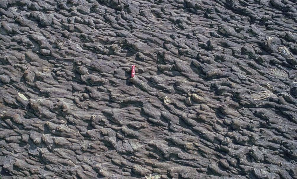
VII. 8.1.7 – F6 and its facies boxes
F6 deposits, which are certainly the most common in exposed turbidite successions, consist of fine to very fine-grained sandstone, siltstone and mudstone divisions that were deposited by turbidity currents in their waning turbulent state. These sediments can be viewed as the “classical” turbidites of Walker (1967), Walker and Mutti (1973) and Walker (1978), i.e., sediments that can be described according to the model of the Bouma sequence (Figure 251). As discussed below, great caution should however be used in many cases because of serious departures from the model. The same sediments were grouped into F8 and F9 facies by Mutti (1992).
In their ideal expression, F6 turbidites are bipartite beds each including a lower sandy portion transitionally overlain by a mudstone division. The sandy portion may contain a basal, graded or ungraded structureless division herein thought to be the deposit of “en masse” deposi-
tion (Middleton, 1967) produced by high rates of fallout from an overlying suspension (F6-1). This sandy division is the genuine expression of the a division of the Bouma sequence (Mutti, 1992). For decreasing rates of fallout, the same division may instead aggrade through relatively thick and generally thinning-upward laminae probably recording a phase of traction carpet sedimentation, i.e., a layer-by-layer sedimentation with reduced traction along the bed (F6-2) (Figures 256-259). With decreasing rates of fallout, the basal division is overlain by thin to very thin parallel and horizontal laminae (b), in turn overlain by current-ripple laminae (c). Through very fine-grained sinousoidal or parallel laminae (d), generally barely visible in outcrop, the sandy portion of the bed grades into an overlying mudstone division (e). This is the complete development of the Bouma sequence with its a, b, c, d, and e divisions. Based on my personal experience, these ideal beds are extremely rare to observe, though the model is very useful as a reference or norm.
CHAPTER II: Turbidites TURBIDITE SYSTEMS: AN OUTCROP-BASED ANALYSIS 244
Fig. 250 - Base of a sandstone bed ornamented with flute casts recording diffuse bed erosion by small scale vortexes. Miocene Marnoso-arenacea Formation, northern Apennines.
BOUMA SEQUENCE
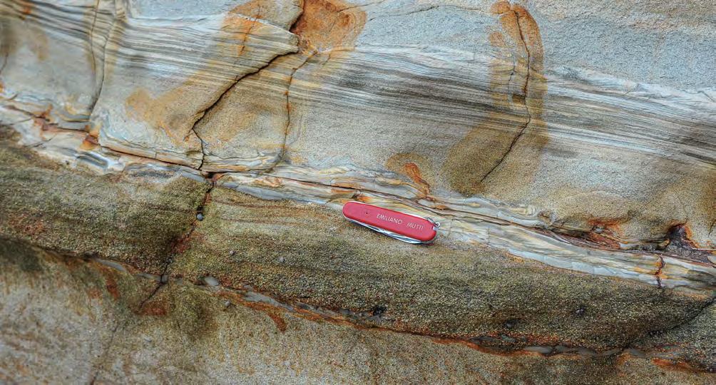
Medium- to coarse-grained sandstone with medium-scale cross-laminae (F4)
of
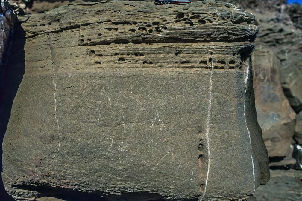
Ripple laminae (c)
Parallel laminae (b)
Fine-grained strucureless sandstone (a)
II:
TURBIDITE SYSTEMS: AN OUTCROP-BASED ANALYSIS 245
CHAPTER
Turbidites
Fig. 251 - Genuine Bouma sequence with well-developed a,b and c divisions. Note flame structures at the base of the bed. Note also the gradual transition between the three divisions without breaks in grain size. Below, is a sharp-topped coarse-grained sandstone bed (F3). The two “beds” might also be part
the same event. Early Cretaceous Maceió Formation, Sergipe-Alagoas basin, Japaratinga, Brazil.
Fig. 252 - F6-1 bed showing the Bouma sequence. Note the fine-grained texture. Eocene Katavia Flysch, Island of Rhodes, Greece.
a b c
Ripple and convolute laminae
F9a F8
Fine-grained structureless sandstone (a)
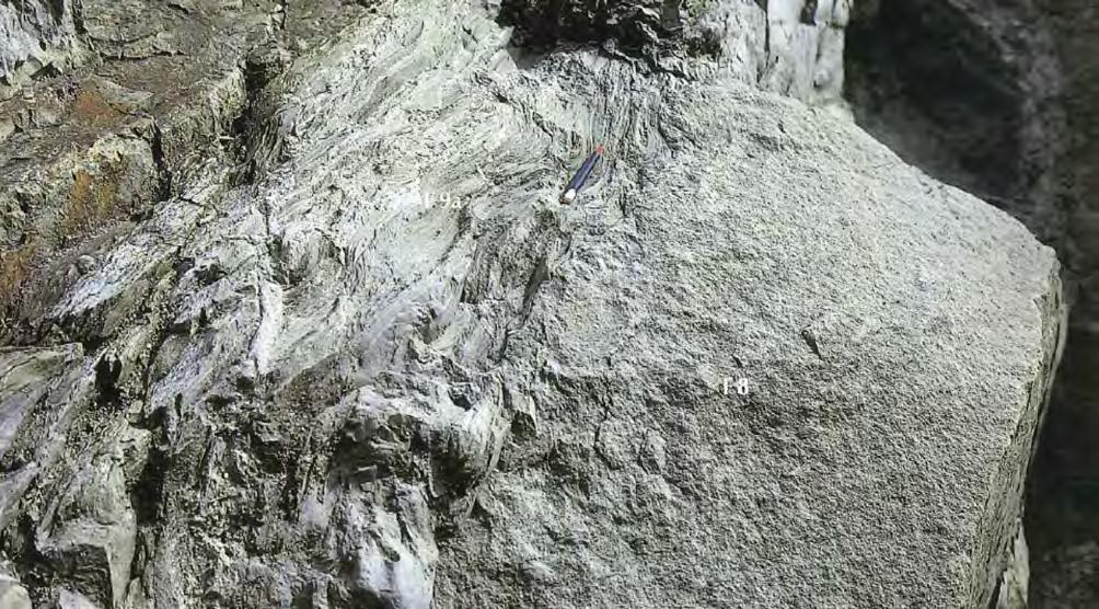
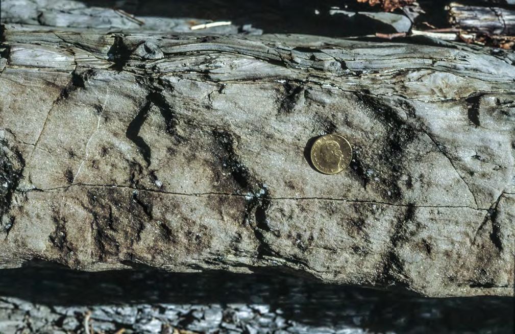
fine-grained structureless sandstone
ripple laminae
CHAPTER II: Turbidites TURBIDITE SYSTEMS: AN OUTCROP-BASED ANALYSIS 246
Fig. 253 - F6-1 bed. Bouma sequence lacking the b division (parallel laminae). Residual excess pore pressure of the structureless division has plastically deformed the overlying divisions. Miocene San Salvatore Sandstone (Bobbio Formation), northern Apennines.
Fig. 254 - F6-1 bed. Fine-grained structureless division (a) directly overlain by a ripple-laminated division (c). Miocene Cervarola Sandstone, northern Apennines.
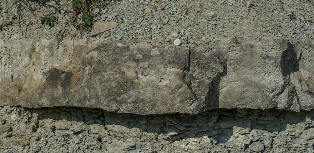
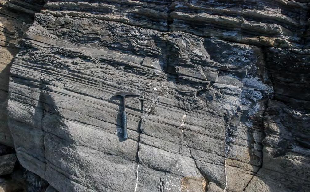
CHAPTER II: Turbidites TURBIDITE SYSTEMS: AN OUTCROP-BASED ANALYSIS 247
Fig. 255 - F6-1 bed. Lower part of a Bouma sequence (a and b divisions) from a small, sand-rich and poorly-efficiency system. The a division consists of a structureless graded sandstone: the b division is made of few parallel laminae capped a set of ripples forming the c division (not visible in the photograph). Beds of this type result from small, short-lived flows with very small proportions of fines. Tertiary Piedmont Basin, northern Italy.
a b
Fig. 256 - F6-2 bed. Note thinning upward traction carpets (thick laminae) below the b Bouma division. Oligocene Macigno, northern Apennines. Courtesy of Gianluca Cornamusini.
Ripple laminae
Thin parallel laminae
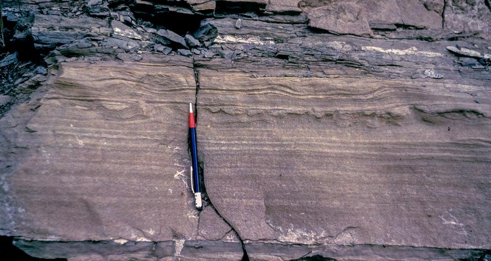
Thick parallel laminae
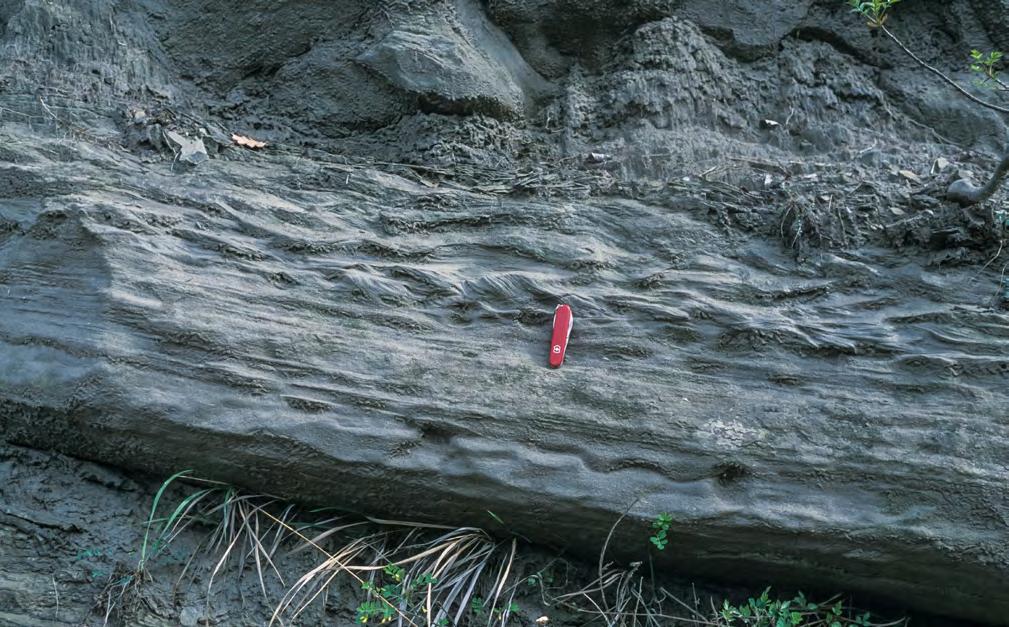
CHAPTER II: Turbidites TURBIDITE SYSTEMS: AN OUTCROP-BASED ANALYSIS 248
Fig. 257 - F6-2 bed. Thick parallel laminae replacing the a Bouma division under conditions of reduced rate of sediment fallout. Cretaceous, Simi Mountains, California.
Fig. 258 - F6-2 bed. Miocene Marnoso-arenacea, northern Apennines. Thin horizontal laminae of the b division overlie a basal cm-thick structureless division, probably a remnant of supercritical bedforms, which are common in overlying and underlying beds.
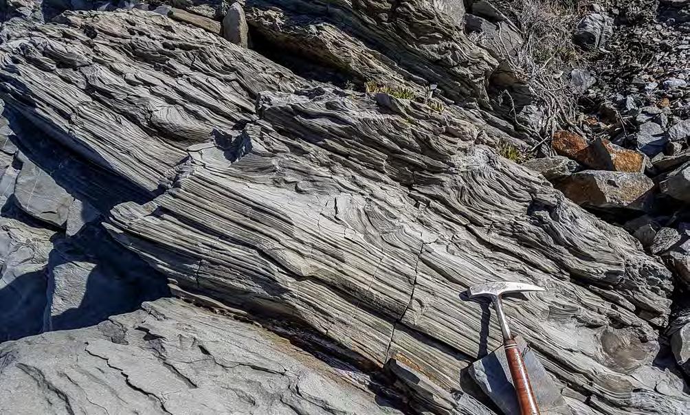
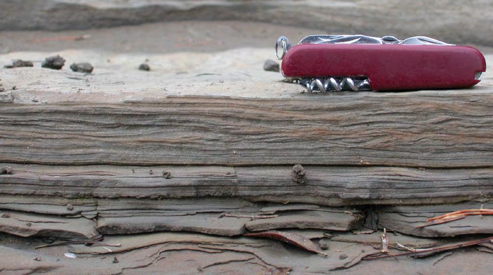
Ripple laminae (c)
Parallel laminae (b)
CHAPTER II: Turbidites TURBIDITE SYSTEMS: AN OUTCROP-BASED ANALYSIS 249
Fig. 259 - F6-2 bed. The classic b and c Bouma divisions. Oligocene Macigno, northern Apennines. Courtesy of Gianluca Cornamusini.
c b
Fig. 260 - F6-3 bed. Sandstone bed showing parallel and ripple laminae of the b and c divisions of the Bouma sequence. Eocene Hecho Group, south-central Pyrenees.
Bed
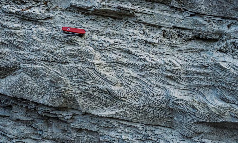
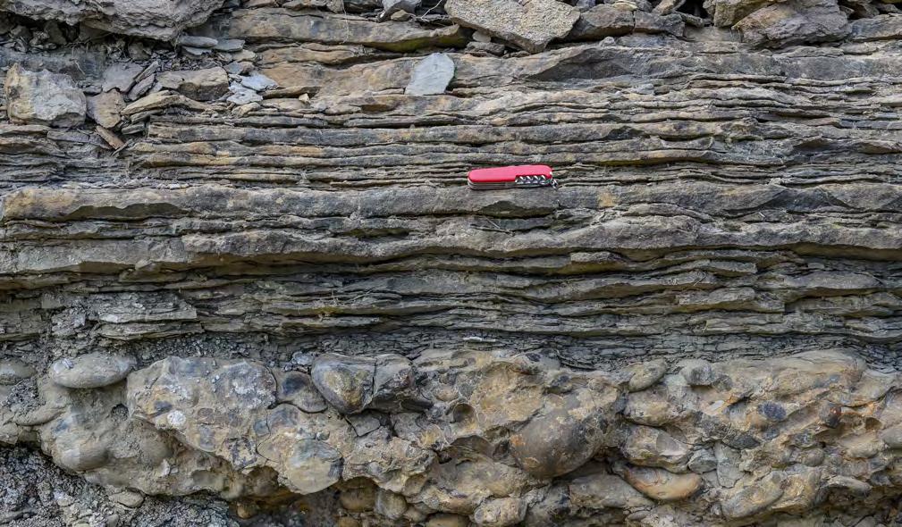
CHAPTER II: Turbidites TURBIDITE SYSTEMS: AN OUTCROP-BASED ANALYSIS 250
Fig. 261 - F6-3 bed. Climbing ripples (Bouma c division). Miocene Laga Formation, northern Apennines.
Fig. 262 - F6-3 beds. Closely-spaced thin, wavy sandstone beds (Tc-e units) with virtual no mudstone partings overlying a F1 bed. These beds are common in channel-margin settings. Eocene Hecho Group, south-central Pyrenees.
Most commonly, F6 beds lack the basal structureless division thus being made of current-laminated divisions (b through d) capped by mudstone (F6-3). Beds of this type are ubiquitous in turbidite successions being deposited by different processes and in different turbidite elements. Dilute hyperpycnal flows form huge accumulations of this facies in delta slope elements; overbank processes account for similar accumulations in channel-levee complexes and, to a lesser degree, within many channels. The typical element of this kind of deposits are however the basin plains, particularly in ponded basins, which are reached by distal and dilute turbidity currents. These beds display a great degree of variability in terms of individual thickness, sand:mud ratio and internal structures (Figures 260-262).
There are no general criteria to classify F6 deposits, especially F6-3 beds, nor many attempts have been made in this direction. Mutti and Ricci Lucchi (1975) and Mutti (1979) attempted to subdivide them based on sand: mud ratio and introduced their D1, D2 and D3 facies. This might be a convenient approach for descriptive purposes. A further attempt was made by Mutti (1992) who made a clear distinction between F9a and F9b facies (Figures 263-264). F9a are made up of well-developed and well-sorted b through c divisions and thought to be the deposit of similarly well-developed traction-plus-fallout processes; F9b are mostly thin Tc-e beds with poorly developed internal structures and poorer sorting, suggesting deposition from short-lived immature suspensions. In most cases, these deposits are simply thin sandstone beds with a rippled upper surface. If not carefully observed and framed within their association, these beds can be mistaken for F4-3 beds (see above) or plumites (see later). Mudstone caps are typically thicker in F9a beds and considerably thinner in F9b beds. Basically, F9b beds seem the product of poorly efficient, short-lived and mud-poor flows typical of relatively small sand-rich systems.
Great departures from idealized models are observed where dilute turbulent flows undergo ponding, reflection and deflection against bounding slopes of confined basins or intrabasinal “highs”. Settings of this kind have been analyzed in great detail particularly by Remacha et al., 2003; Remacha and Fernandez, 2005, Magalhaes and Tinterri, 2010, and Tinterri and Muzzi Magalhaes, 2011. In these cases, an almost endless series of modifications are imparted to the resulting beds herein termed F6-4. These settings, which are of local significance, have to be studied on a case-by-case basis. More generally, however, it can be safely said that F6 deposits have received little attention from
sedimentologists so far. Their better understanding should provide a very useful tool for the analysis of turbidite systems due to their common occurrence in outcrops and cores and to their extreme facies variability (see photographs).
The abundance of F6 deposits in a system is strictly a function of the amount of fines that turbidity currents contain in their original parental flow or have been eroded from the bed and resuspended within the flow during its motion. A high content of fines promotes flow efficiency; the contrary generates flows that have reduced mobility. Care should be exerted in basins affected by bottom currents which may resuspend these fines and transport them far away to form contourites (e.g., Mutti and Carminatti, 2012). The problem is more amply discussed in the final chapter. Similar care should also be exerted in those cases where mud incorporation is so important that the flow becomes cohesive (see later).
VII. 8.1.8 – A final note on hydraulic jump-related deposits
Growing evidence suggests that hydraulic jumps are an important, though poorly understood process of turbidity currents (see above). The process is increasingly reported in the literature by both marine and landbased sedimentologists, but the problem remains as to how we can recognize its record on facies characteristics, say at the bed scale. Some examples are discussed below in the attempt to have some possible insights on this fascinating flow transformation when observing the rock record.
A basic point on which there seems to be a general consensus is that hydraulic jumps imply localized bed erosion produced by intense turbulence. The presence of scours is thus the first evidence of the process, though turbulence-related scours may vary in scale from a small flute cast (e.g., Dzulynski and Sanders, 1965) to large km-scale scours detected by marine geology (e.g., Mutti and Normark, 1987; Wynn et al., 2002). At outcrop scale, flutes and m-scale scours can only be observed. Figure 267 portrays a mud-draped scour that clearly show as a bypassing flow left a scour in an underlying deposit which was successively filled with a series of thin-bedded turbidites. The bypassing flow clearly produced bed erosion and incorporated through resuspension the sediment removed through the process (sand and mud clasts). This is the reasonable expression at outcrop scale of a hydraulic jump, though only erosional.
CHAPTER II: Turbidites TURBIDITE SYSTEMS: AN OUTCROP-BASED ANALYSIS 251
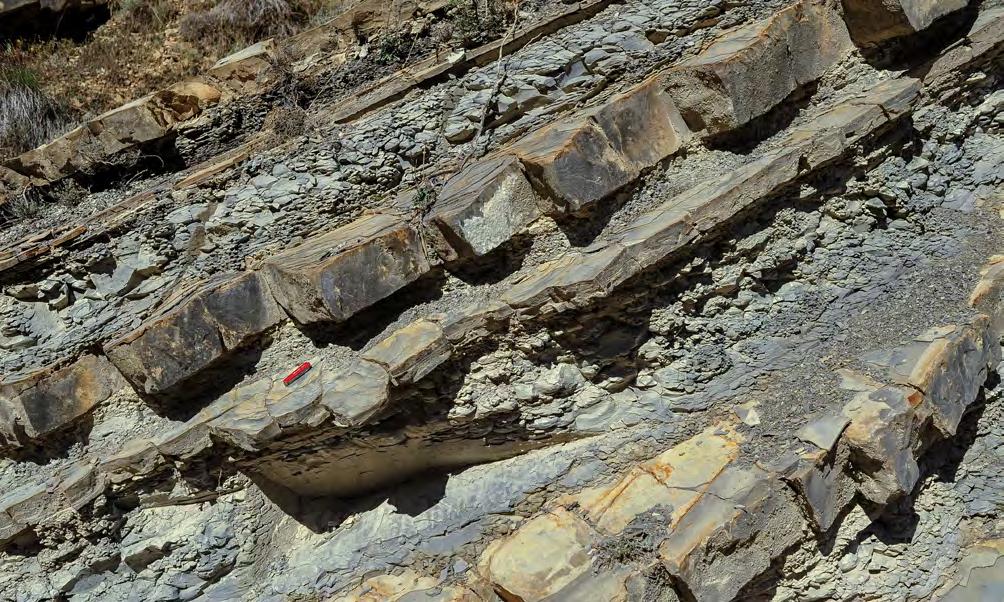
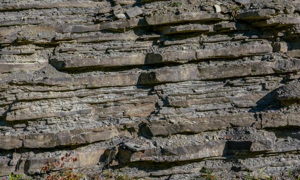
CHAPTER II: Turbidites TURBIDITE SYSTEMS: AN OUTCROP-BASED ANALYSIS 252
Fig. 263 - F6-3 beds displaying well-developed parallel and ripple laminae and thick mudstone caps. Beds of this kind are typically found in basin-plain elements and are characterized by a parallel-sided geometry over considerable distance. These beds are the F9a facies of Mutti (1992). Eocene Hecho Group, south-central Pyrenees.
Fig. 264 - F6-3 beds with the characteristics of F9b of Mutti (1992). Internal structures are poorly developed and bedding geometry is irregular. Most thin and very thin beds can be better interpreted as plumites. Late Eocene-Oligocene Ranzano Sandstone, northern Apennines.
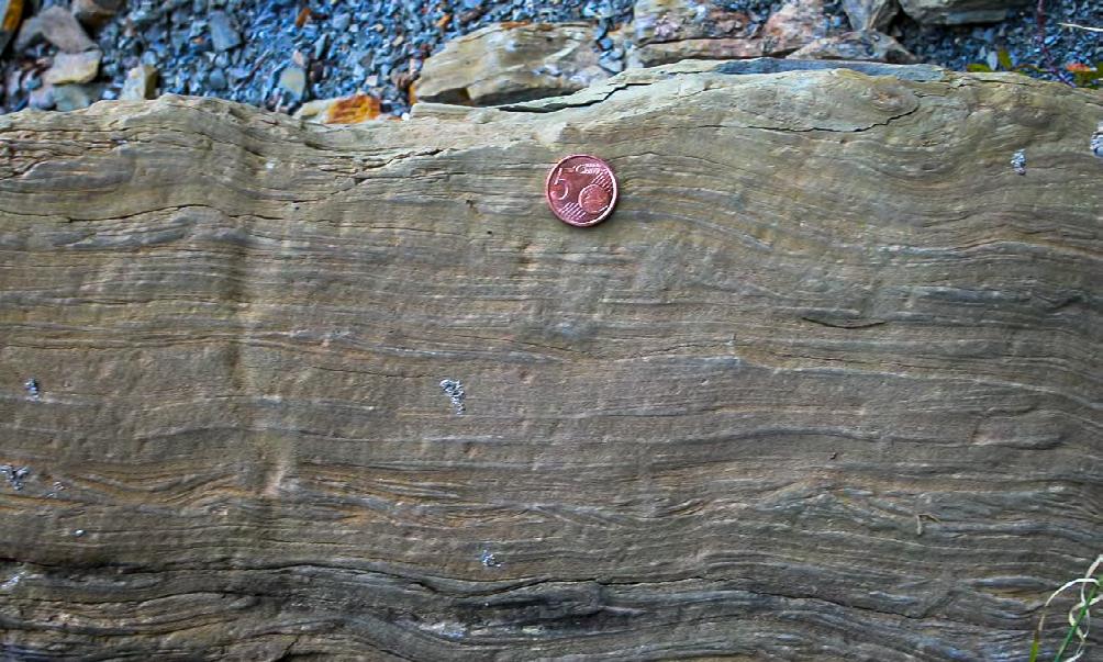
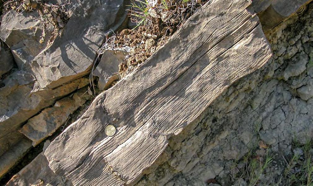
CHAPTER II: Turbidites TURBIDITE SYSTEMS: AN OUTCROP-BASED ANALYSIS 253
Fig. 265 - F6-4 bed, showing departures from normal F6-3. Note ripples at the base, internal wedging and truncation of laminasets. These beds occur in a highly confined basin with reflection processes. Upper Cretaceous Vallcarga Formation, south-central Pyrenees.
Fig. 266 - F6-4 bed showing alternation of parallel- and ripple-laminated divisions, probably generated by reflection against a bounding slope. Eocene Hecho Group, south-central Pyrenees.
Mud-draped scour
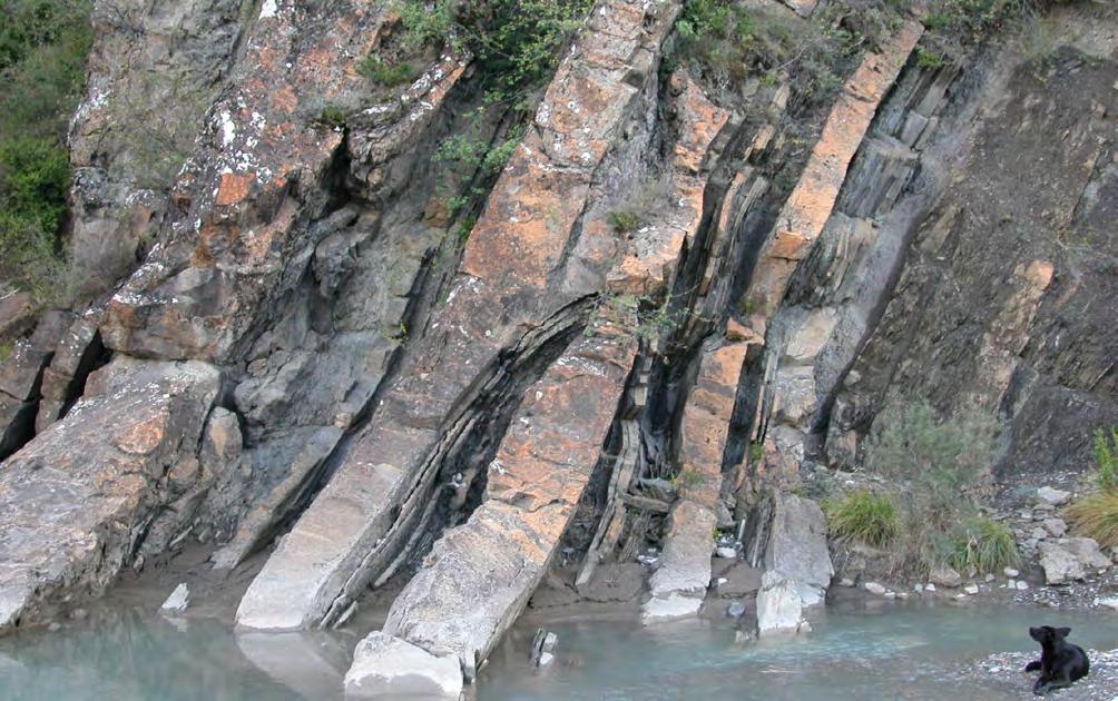
Figure 268 shows a bed consisting of a basal division of very low-angle cross laminae, interpreted as supercritical bedforms (see Figure 163) overlain by migrating megaripple bedforms. Fedele et al. (2016) have recently suggested that dunes (megaripples) can form in both subcritical and supercritical flows. Though I concur with these authors that comparing bedforms of sediment gravity flows with those of subaerial bedform regimes may be potentially misleading, I also argue that the megaripples of Figure 268 as well as those of F4 deposits (see above) are strictly similar to those observed in fluvial sediments and in particular they never show lateral changes into antidune reverse flow conditions (backsets) or downstream dipping low-angle cross laminae that would be expected in supercritical flows. I therefore maintain my conclusion that these bedforms are a typical expression of subcritical flows. The stratigraphic relationships shown by Figure 268 clearly indicate that a supercritical flow passes to subcritical conditions for a normal and natural process of deceleration and supercritical features are suddenly replaced by subcritical features. The change is marked by a more or less erosional surface commonly paved with mudstone clasts. The surface is the expression of bed erosion at the jump.
A different but equally interesting example of hydraulic jump is shown in Figure 269. The bed below (Bed 1) contains a basal division of medium- to fine-grained sandstone with parallel and wedge-shaped low-angle cross laminae with grain-size banding, interpreted as a supercritical antidune deposit. With an apparently transitional contact, this basal division is overlying by a division of well-developed climbing ripples capped a thin mudstone. The bed above (Bed 2) displays the same two facies but includes an intervening scour with a steep upcurrent wall which is filled in with structureless sandstone with some crude cross laminae in its most upcurrent portion. The scour and its infill are here interpreted as the record of a hydraulic jump within the same flow which probably developed at the expenses of the denser basal flow (see 2-phase suspension flow of Postma et al., 2009) and forced the flow to subcritical conditions.
The examples above are very limited but should encourage to look at the rock record more carefully since it contains a wealth of information which is certainly underexploited. This information may considerably help explorationists predict basinward extent of sandbodies and their petrophysical characteristics.
CHAPTER II: Turbidites TURBIDITE SYSTEMS: AN OUTCROP-BASED ANALYSIS 254
Fig. 267 - Example of mud-draped scour thought to be produced by a local hydraulic jump. The scour is filled with thin sandstone beds. Dog for scale. Eocene Hecho Group, south-central Pyrenees. Beds are overturned.
F4
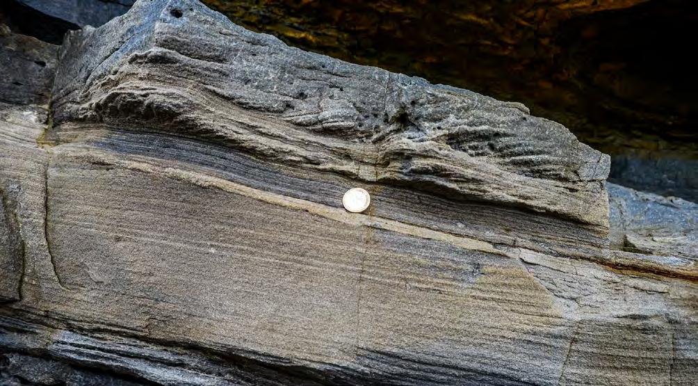
F3
Truncation surface
Supercritical laminae (antidunes)
Climbing ripples (subcritical)
Supercritical laminae (antidunes)
Cross laminae
Parallel laminae
Low-angle cross laminae
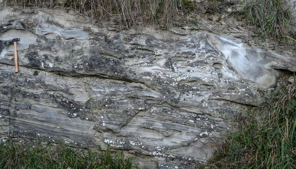
Climbingripples (subcritical)
HJ
supercritical and
CHAPTER II: Turbidites TURBIDITE SYSTEMS: AN OUTCROP-BASED ANALYSIS 255
Fig. 268 - Contact (indicated by large red arrow) between F3 deposits (sand deposited by a supercritical suspension) and F4 deposited by a subcritical flow through migrating dunes. Eocene Guipúzcoa Flysch, northern Spain.
Fig. 269 - Example of hydraulic jump. The bed below (Bed 1) shows an apparently transitional contact between supercritical antidunes and subcritical climbing ripples. The bed above (Bed 2) shows the same succession but also a clear internal scour (HJ) intervening between the two facies. The scour is filled in with structureless sand displaying some faint cross laminae dipping in a downcurrent direction (right). The scour and its infill are interpreted to represent a local hydraulic jump accounting for the change between
subcritical flow conditions. The same change must be inferred also for Bed 1, though the hydraulic jump ha not left record here. Miocene Marnoso-arenacea, northern Apennines.
Bed 2
Bed 1
CHAPTER III
CHAPTER IIIA (FLOOD-DOMINATED FLUVIO-DELTAIC SYSTEMS)
I - A PREMISE
In this chapter, we will first review some basics of classic fluvial and deltaic sedimentology and will then expand on the importance of flood-dominated fluvio-deltaic systems, a group of depositional systems which is still poorly known and largely overlooked in the literature. These systems are conversely among the volumetrically most important components of many exposed basin fills of orogenic belts and probably of many other geodynamic settings. I will then describe and discuss the ways in which these flood-dominated sediments undergo more or less substantial reworking by tides and, to a lesser degree, by waves, suggesting an easy comparison with deep-water settings where turbidite sedimentation is reworked and even replaced by bottom currents, giving way to mixed and contourite systems.
Because of health problems, this chapter was written more than one year later than the two previous chapters. Despite this temporary inconvenience, the delay turned out to be very useful in allowing to incorporate in this chapter and particularly in the final conclusions some of the points of a number of papers published between 2017-2019 on hyperpycnal flows, turbidity currents and their deposits. This has forced to complement and, in some cases, partly revise what had already been written, showing, for better or worse, how fast research is moving today. This also shows how difficult is writing a textbook when information and related problems grow so fast. New data and new relevant papers can now improve our knowledge and modify our ideas on an almost every-day basis.
II - INTRODUCTION TO FLOOD-DOMINATED ALLUVIAL AND FLUVIO-DELTAIC SYSTEMS
In the previous chapter we have described and discussed in detail the characteristics of deep-water tur-
bidite systems and the many problems that this kind of sediments still raises as to their interpretation. As mentioned in the introduction of Chapter I, sediment gravity flows do not only dominate sedimentation in deep-waters, but are also a fundamental process in alluvial and shallow marine environments of tectonically-active basins, resulting in the deposition of oneevent beds sharing many features with beds deposited in deep-waters by similar flows. Large accumulations of conglomerates, pebbly sandstones and sandstones deposited by such flows are thus a fundamental component of many alluvial and deltaic systems (Figure 270). In some delta-front settings these deposits form sandstone bodies with considerable thickness and lateral extent made up of graded and tabular beds that so closely resemble turbidite sandstone beds that one would be hard-pressed to see any difference based on one outcrop (Mutti et al., 1996; Mutti et al., 2007). These delta-front sandstones can be regarded as a sort of “shallow-water cousins” of deep-water turbidites, thus strengthening the close relations between turbidite and deltaic sedimentation. Fluvial floods of sufficient magnitude and sediment concentration and their propagation in seawaters as hyperpycnal flows (see later) are the only plausible process to account for these sediments. Fluvial floods and related sediment gravity flows are equally important for explaining facies characteristics and sand-body geometry of many alluvial and lacustrine fluvio-deltaic deposits.
It should be clear that fluvial floods, though with their episodic character, are part of the day-to-day processes governing modern sedimentation in many alluvial environments. As such, they are included in the classic architectural elements of Miall (1985) and referred to by this author as “sediment gravity flow” (SG), “Laminated sand” (LS), and “Overbank fines” (FF). Typical examples are debris flows and sheet floods in alluvial fans or in immature braided streams; classical flood deposits are especially the sand beds deposited from suspended load associated with overbanking in levees and adjacent flood plains or late flood-stage deposition in many rivers (Figure 271). Stanley (1968) first noted the strong similarities of these beds and their internal structures with typical turbidite Bouma sequences. The point emphasized herein is that the above flood processes are part of the “normal” everyday fluvial sedimentation, though their deposits comprise
CHAPTER III TURBIDITE SYSTEMS: AN OUTCROP-BASED ANALYSIS 256
a subordinate portion of modern fluvial systems. The bulk of modern fluvial and deltaic sedimentation is actually dominated by normal bedload and suspended load mechanisms. Conversely, the stratigraphic record shows that flood-related processes, with a much higher degree of catastrophism, were dominant in alluvial and deltaic systems of tectonically mobile basins over long periods of times. As a result, most stratigraphic successions are composed of facies and facies associations produced by catastrophic flood-generated sediment
gravity flows in both continental and shallow-marine domains. As we will see later, this does not mean that “normal” processes were not active at the same time; it simply means that catastrophic deposits have a higher preservation potential and that, during certain periods of times, they are highly frequent, recording a sort of “normal” deposition with which we are not familiar. This implies that the saying “the present is the key to the past” needs to be partly reconsidered in terms of “normal” vs “catastrophic” or “episodic” processes.
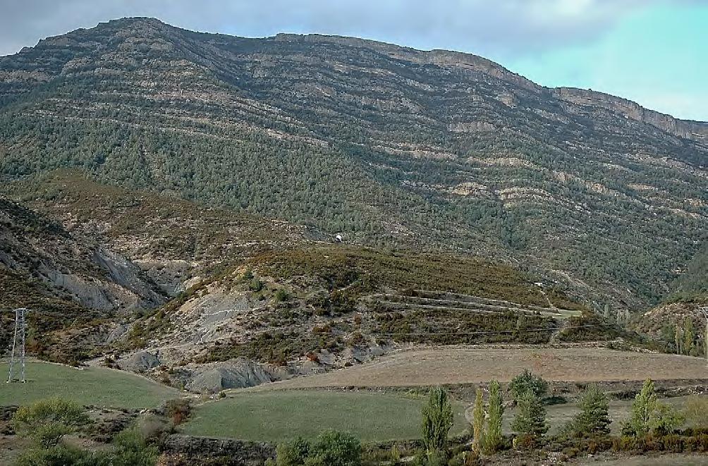
CHAPTER III TURBIDITE SYSTEMS: AN OUTCROP-BASED ANALYSIS 257
Fig. 270 - Impressive succession of flood-dominated deposits in the Eocene and Oligocene of the south-central Pyrenees (Jaca basin). From base to top: 1) prodeltaic or delta-slope mudstones (Pamplona Marl), 2: flood-dominated fan-delta deposits consisting of partly covered, shallow-marine graded sandstone and pebbly-sandstone lithofacies (Atares delta), and 3): alluvial-fan conglomerates (Santa Orosia conglomerates)
Pamplona Marl
Atares delta
Santa Orosia conglomerates
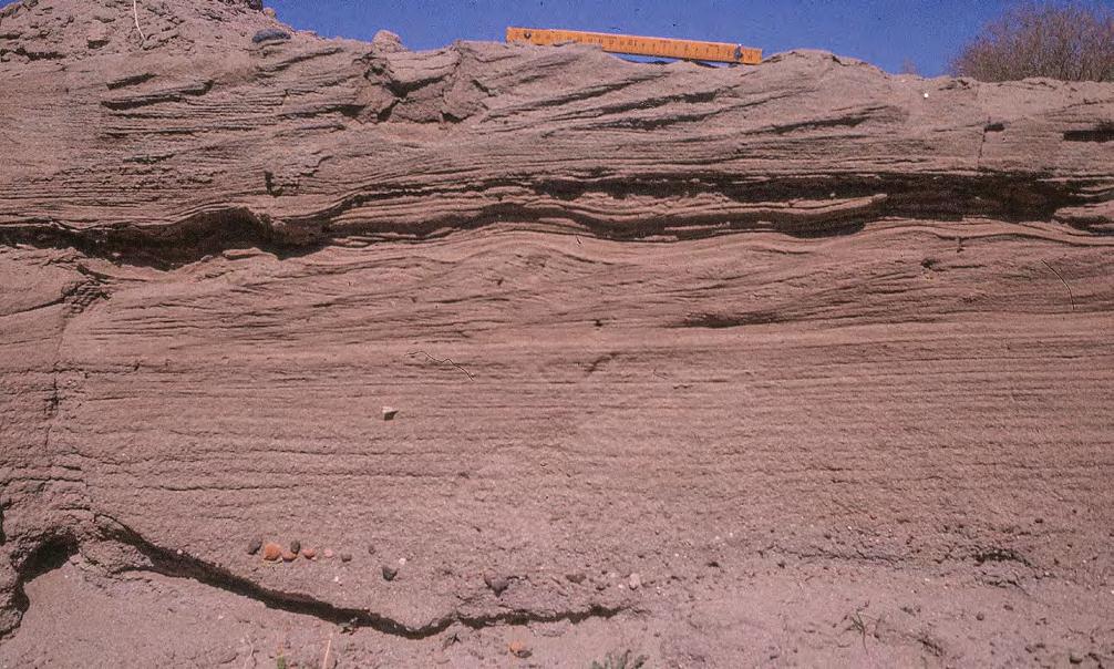
Some basic questions concerning this problem were raised by Dott (1983) in a paper that was a sligthtly modified version of the Dott’s SEPM presidential address in Calgary, Alberta, in 1982. The questions raised by Dott are very simple but address basic problems in sedimentary geology: (1) “Do sedimentary rock record mainly average, continuous, dayto-day processes or relatively rare, large-magnitude ones separated by long non-depositional intervals1”; (2) “How normal is any so-called average condition?”, and (3) “How rare are so-called rare events?”. Dott (1983, p.6) also notes “…. that, more than we realize, our pet doctrine of uniformitarianism – even a modern version thereof under whatever rubric – casts subtle constrains upon our thinking”. As a result, we are strongly biased toward average conditions and favor continuity rather than discontinuity in the stratigraphic record. Where changes are undeniable and repetitions occur, we invoke cyclicity, which Dott
(1983) sees as a special form of uniformity – that is, uniform change with uniform deviation from the norm, and with uniform repetition rates.
The interested reader will find excellent papers discussing these fascinating problems (e.g., Ager, 1980, 1993; Dott, 1988; Clifton, 1988; Huggett, 1989) and their implications not only in sedimentary geology but also in the creationist-neocatastrophist cause to the point that Dott (1983, p. 9) suggests that the use of the adjective catastrophic together with the noun catastrophism should be reserved only to supernatural phenomena to avoid misunderstanding with the creationists. He therefore suggested the term “episodic” to denote large-magnitude events which represent positive (greater-than-normal) deviations from the norm and are rare on the human time scale. For similar reasons, Clifton (1988) suggested the term convulsive instead of catastrophic or episodic. Seilacher (1991) also coined new terms to denote the deposit of episodic events (Figure 272).
CHAPTER III TURBIDITE SYSTEMS: AN OUTCROP-BASED ANALYSIS 258
Fig. 271 - Modern flood unit displaying internal divisions identical to those of the well-known turbidite Bouma sequence. A. graded, structureless division; B. parallel-laminated division; C. division with ripples, climbing ripples, and sinusoidal laminae. Arrow indicates surface of slight flow re-acceleration. Unrecorded ephemeral stream, Chubut province, Argentina.
A C
B
III - NORMAL VS EPISODIC SEDIMENTATION
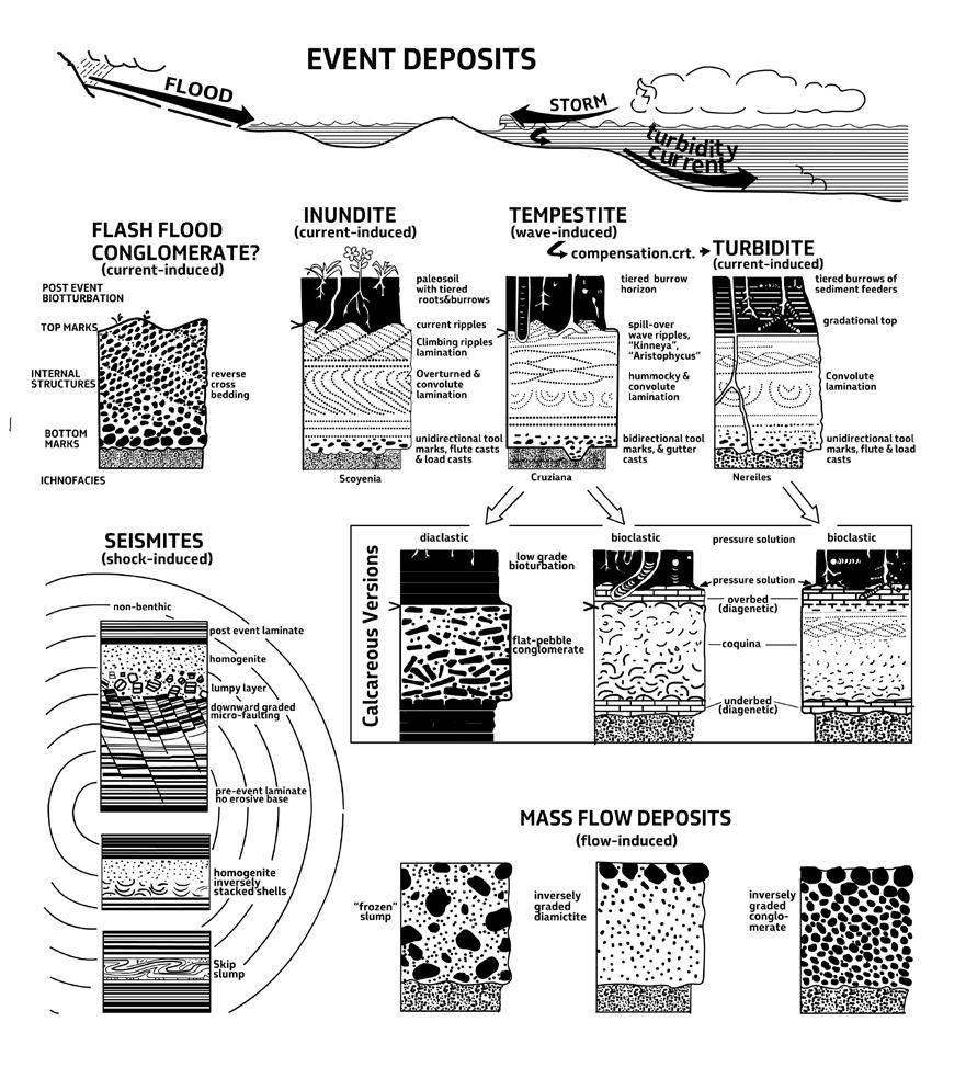
The term catastrophic most commonly describes the concept of an episodic event of large magnitude whose consequences are potentially tragic for the organisms living where the catastrophe occurs. The use of “tragic” is apparently restricted in most cases to events affecting only humans: a somewhat anthropocentric point of view. Unfortunately, we do not know the opinion about catastrophic events of the living organisms that suffered this kind of events millions of years ago. Typical episodic events with a catastrophic connotation are great storms, giant mass failures on continental
slopes, jokulhaups, explosive volcanic eruptions, great earthquakes, giant tsunamis, large asteroid impacts, and a great number of large-volume turbidity currents. These are events of regional influence implying extraordinarily release of energy (see discussion of many pertinent examples in the GSA Special Paper 229 edited by H. E. Clifton, 1988).
What the term “catastrophe” really means in the evolution of geological systems is well beyond the scope of this book. Basically, catastrophic processes do exist
CHAPTER III TURBIDITE SYSTEMS: AN OUTCROP-BASED ANALYSIS 259
Fig. 272 - Types of episodic event bed (after Seilacher, 1991).
and are hierarchically ordered in terms of magnitude and consequences (Figure 273). For our purposes, the assumption is made that catastrophic processes, as observed operating in modern environments, are still part of the “normal” spectrum of fluvial and marine processes, though most of them can be considered as natural disasters. Therefore, some catastrophism is probably inherent also to uniformitarianism, being episodic events of greater magnitude than most common or average events. Setting aside doctrinal implications, the adjective “catastrophic” is used hereafter to simply denote river floods and related processes that generate mixtures of sediment and water of sufficient volume and sediment concentration to deposit gravel, sand and mud far away from their original
fluvial drainage basins in alluvial, nearshore, shelfal, slope and basinal regions, thus progressively increasing the length of transfer zones (Figure 274). These beds can occur in isolation or, most commonly, comprise thick sedimentary successions produced by similar catastrophic conditions over considerable periods of time. In fluvio-deltaic system the degree of catastrophism can be simply appreciated by the amount of sand that flood-generated flows can directly transfer to nearshore and shelfal zones and in some cases to adjacent deep-water basins (see fluvio-turbidite systems, Chapter I). The degree of catastrophism can also be indicated by the distance of final sand deposition from channel-exit, i.e., a measure of flow efficiency.
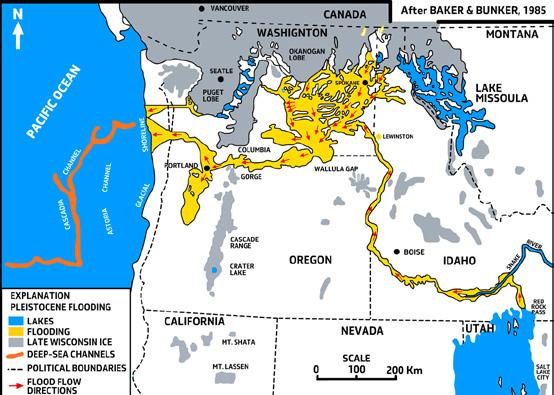
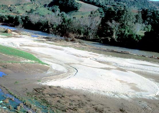
CHAPTER III TURBIDITE SYSTEMS: AN OUTCROP-BASED ANALYSIS 260
A B
Fig. 273 - A. Area of the northwestern United States which was affected by the catastrophic Missoula flood during the Late Wisconsin (from Baker and Bunker, 1985). The flood generated hyperpycnal turbidity currents that deposited thick sequences of sandy turbidites in the Escanaba trough in the Pacific Ocean. B. Small, flood-generated modern sand lobe in the Alfredo Wagner area, Santa Catarina, Brazil.
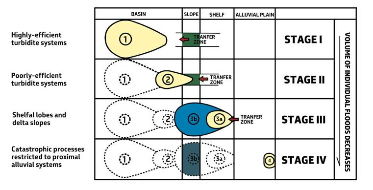
IV - FLUVIO-DELTAIC SYSTEMS: GENERAL CHARACTERISTICS
Terrigenous sediments, in both subaerial and subaqueous environments, are ultimately derived from rivers that transfer clastic particles to their sites of transient or permanent deposition. Along with subaerial and submarine slides, the process accounts for huge accumulations of gravel, sand and mud anywhere on our planet surface. River-born sediments are the main and obvious primary component of alluvial and deltaic successions. The same sediments provide the source for other processes, such as for instance wind, waves, tides, and turbidity and bottom currents that can rework them in eolian systems on land, and in a great variety of depositional systems in shallow- and deep-marine environments. All these processes –commonly collectively referred to as “source to sink” – have the ultimate goal of eroding the mountains and transferring sediment to the oceans. The knowledge of rivers, their processes and sediments are thus the basic key to begin to understand clastic sedimentology.
IV.1 - THE BASIC CONCEPTUAL MODEL
Rivers give way to depositional systems invariably consisting of three genetically interrelated zones (Figure 275): (a) a drainage basin (Zone 1), which supplies sediment and water, (2) a sediment transfer zone (Zone 2), i.e., a river which removes the waste of the drainage ba-
sin, and (3) a terminal depositional zone (Zone 3) where sediment accumulates in alluvial fans, fan-deltas, alluvial plains and deltas (Schumm, 1981). This holds true whatever the scale of the system under consideration. The main implication of Schumm’s concepts for stratigraphic analysis is perhaps that the most complete record of the evolution of ancient fluvial systems with time is likely to be preserved in their final depositional zones because of their higher preservation potential (Schumm, 1981, pp.27-28). Stated in other words, a fluvial system has to be considered as a whole consisting of genetically inter-related zones and the main problem remains how to link facies and processes of the transfer zones with those of the depositional ones. Therefore, a fluvial system has to be described and interpreted also on the basis of a stratigraphic and sedimentological analysis encompassing both zones, or significant portions of them.
The above approach is apparently overlooked in most literature dealing with fluvial sedimentation, where transfer and depositional zones are generally dealt with as two largely independent domains. Available studies and reviews focus specifically on the sedimentology of (a) alluvial fan and fan-delta deposits (Figure 276), (b) fluvial transfer zones, with their classic subdivisions in straight, meandering and braided channels, and related architectural elements (Figure 277), and (c) river-delta systems (Figure 278). The literature covering all these sediments is so abundant that its review would be well beyond the scopes of this book. The
CHAPTER III TURBIDITE SYSTEMS: AN OUTCROP-BASED ANALYSIS 261
Fig. 274 - Idealized model showing how the length of the transfer zones indicates different stages or degrees of catastrophism of floodgenerated flows and their related depositional systems (from Mutti et al., 1996).
reader is referred to Collinson (1986), Rachocki and Church (1990), Blair and McPherson (1994a, 1994b), Bridge (2006), and Miall (1977, 2006) for fluvial and alluvial-fan deposits, to McPherson et al. (1987), Wescott and Ethridge (1990), and Nemec and Steel (1988) for fan-deltas and coarse-grained deltas,
and to Coleman and Wright (1975), Galloway (1975), Wright (1977), Elliott (1986), Orton and Reading, (1993), Reading and Collinson (2006), and Bhattacharya (2006, 2010) for river-deltas (the reader is also referred to the basic text book “Global Geomorphology” by Summerfield, 1991).
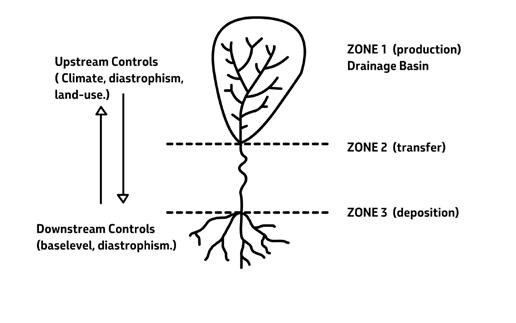
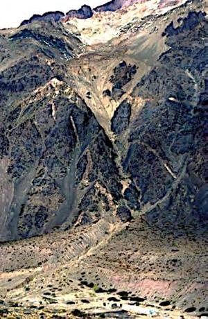

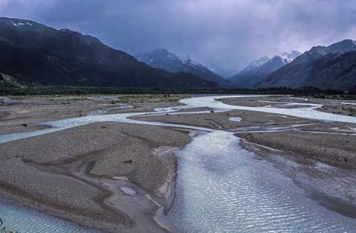
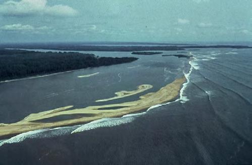
CHAPTER III TURBIDITE SYSTEMS: AN OUTCROP-BASED ANALYSIS 262
Fig. 275 - The fluvial system and its three basic zones (Schumm, 1981).
Zone 1
Patagonia
Patagonia
Zone 1 - Drainage Basin
Zone 2 - Transfer zone
Zone 3- Depositional zone
Cameroon
Zone 2
Zone 3
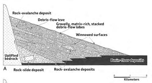
Type-1 alluvial fan (debris-flow dominated).
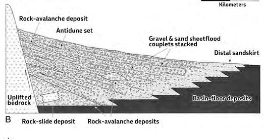
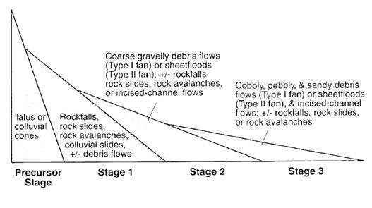
Type-2 alluvial fan (sheet-flood dominated).
Evolutionary stages of alluvial fans with time and increase in size.
The great number of depositional models discussed in the above literature is largely derived from modern alluvial and deltaic systems and heavily based on modern rivers. Accordingly, processes are primarily those operating in modern environments, particularly in alluvial and nearshore deltaic settings where every day processes and resulting deposits can be easily and directly observed.
Debris flows and sheet floods predominate in alluvial fans (piedmont-type, in the sense of Blair and McPherson, 1994a, see later) and in the alluvial component of fan-deltas (e.g., Miall, 1978; Blair and
McPherson, 1994a, 1994b); tractive currents moving sands and gravels as bedload are thought to predominate in river systems characterized by a variety of channel styles, bars, and bedforms (e.g., Walker, 1976; Miall, 1978, 2006); and waves, tides, storms, sediment gravity flows, fluvial plumes, slumps and large-scale sediment failures account for much of the final phases of sediment transport and deposition in the marine components of both fan-deltas (e.g., Nemec, 1990; Orton and Reading, 1993) and river deltas (e.g., Coleman and Wright, 1975; Galloway, 1975; Elliott, 1986).
CHAPTER III TURBIDITE SYSTEMS: AN OUTCROP-BASED ANALYSIS 263
A B C
Fig. 276 - Evolutionary stages of an alluvial fan system (after Blair and McPherson, 1994).
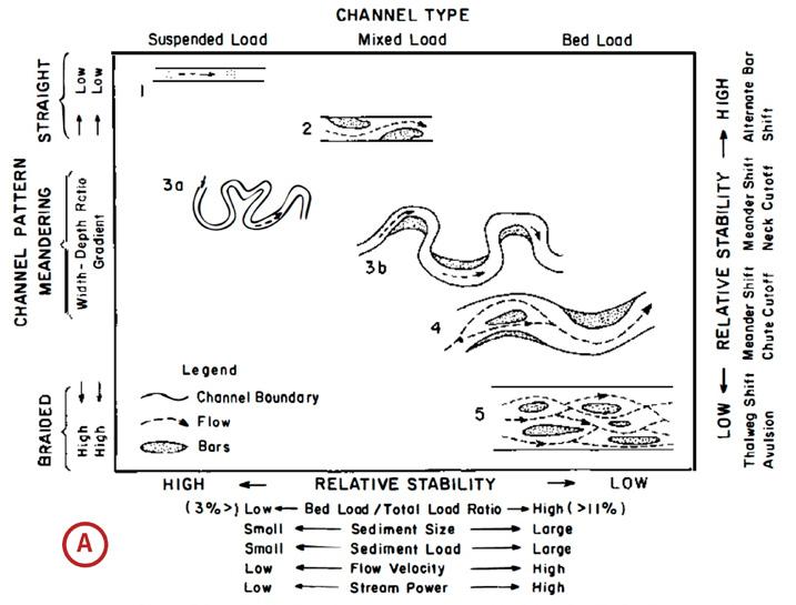
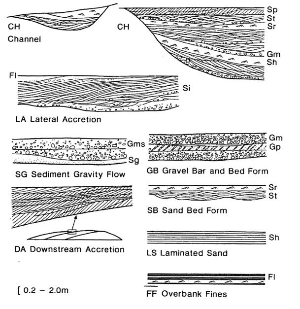
CHAPTER III TURBIDITE SYSTEMS: AN OUTCROP-BASED ANALYSIS 264
A B
Fig. 277 - A. Fluvial channel classification according to Schumm (1981); B. Architectural elements for the analysis of fluvial deposits according to Miall (1985).
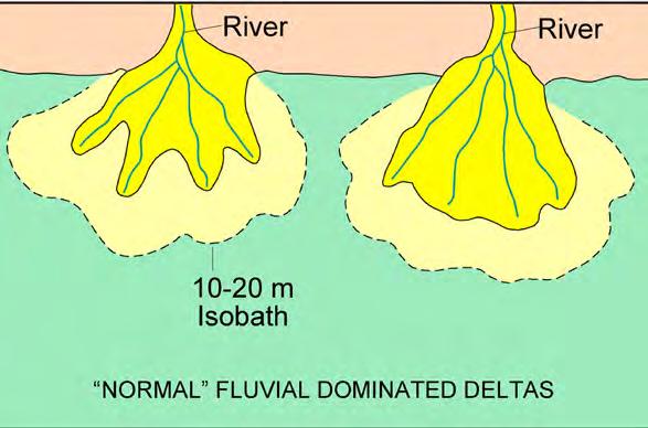
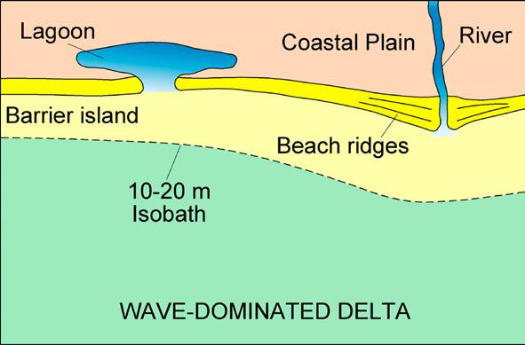
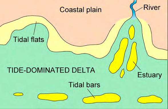
CHAPTER III TURBIDITE SYSTEMS: AN OUTCROP-BASED ANALYSIS 265
Fig. 278 - The three main types of delta according to the ternary classification of Galloway (1975) (see also Coleman and Wright, 1975).
In both marine and lacustrine fan-deltas and river deltas, the density contrast between the river water and that of the receiving basin plays a major role in determining the sediment distribution pattern (Figure 279). Entering a standing body of water (lakes, seas), effluent river water can produce hypopycnal, homopycnal or hyperpycnal flows (Bates, 1953). Hypopycnal flows (less dense than basin waters) can only form in denser sea water and undergo rapid deposition of bed load at river mouth; suspended load generates buoyant turbid plumes that carry fines basinward in prodeltaic, shelfal and slope regions; homopycnal flows (equally dense than basin waters) undergo rapid mixing at
river mouths followed by deposition of both bedload and suspended load over short distance; high-density outflows (denser than basin waters) move along the bottom as hyperpycnal flows, or underflows, causing sediment to escape the shoreline (see Elliott, 1986 for a review). As we will see in the following sections, these density differences are fundamental in the process of delta upbuilding and the resulting types of deposits. In particular, hyperpycnal flows are a basic process in the formation of flood-dominated deltas (see later). The importance of hyperpycnal flows as related to turbidite deposition has been discussed in Chapter II and will be reemphasized in later sections.
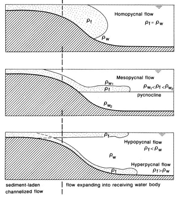
CHAPTER III TURBIDITE SYSTEMS: AN OUTCROP-BASED ANALYSIS 266
Fig. 279 - Hypopycnal, homopycnal, mesopycnal, and hyperpycnal flows (after Mulder and Alexander, 2001). Homopycnal and mesopycnal flows are not discussed herein.
The classic depositional models of alluvial and deltaic sedimentation that can be derived from the comparison of modern and ancient sediments are highly diversified and offer a very fragmentary view of fluvial systems in terms of possible relationships between transfer and final depositional zones. The problem can be clearly appreciated by considering the classic ternary classification of river deltas in fluvial-, wave-, and tide-dominated depositional systems proposed by Galloway (1975) (see Figure 278), and implicit also in the work of Coleman and
Wright (1975), who emphasized how sand distribution patterns of delta systems substantially differ from each other depending on the prevailing process(es) (Figures 280 and 281). Fluvial processes end at the shoreline, and even farther up-stream of it, in both wave- and tide-dominated systems, thus preventing any possible comparison between processes and deposits of the fluvial transfer zones and those of delta-front depositional zones where river-born sediment is redistributed by waves and tides.
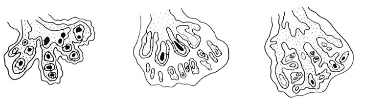
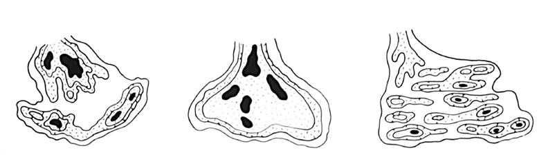
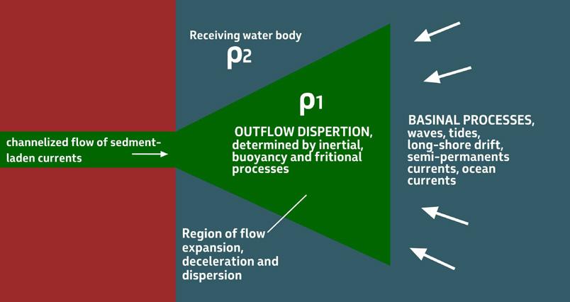
CHAPTER III TURBIDITE SYSTEMS: AN OUTCROP-BASED ANALYSIS 267
Fig. 280 - Sand distribution patterns as controlled by fluvial and marine diffusion processes. A. river dominated; E. wave dominated; F. tide dominated (after Coleman and Wright, 1975).
A D B E C F
Fig. 281 - Some of the main factors controlling outflows at river mouths (from Mutti et al., 1996; slightly modified from Elliott, 1986).
IV.2 - SOME BASIC RELATIONSHIPS BETWEEN FLOW VELOCITY AND DEPTH, GRAIN SIZE, AND BEDFORMS
IV.2.1 – Bed load structures
In the mid Sixties, flume experiments developed by the US Geological Survey (Simons et al., s1965) and observations of modern sediments in shallow trenches in the Rio Grande bed near El Paso (Harms and Fahnestock, 1965) showed that velocity and depth (depth will be omitted hereafter) of a unidirectional flow – an ideal river –, determine bed load transport through migrating bedforms with well-defined configurations produced by tractive processes. These contributions still represent a benchmark in sedimentology. Figure 282 shows an excellent example of these bedforms (ripples and megaripples) preserved in fluvial deposits of the Eocene Castissent Group in the south-central Pyrenees.
As indicated in Figure 283, for a grain size population in the range of medium and coarse sand, both experiments carried out with increased flow velocity and field observations show the transition from a static bed without particle transportation to bed load movement
through migrating ripples, megaripples and plane bed configuration. For the interested reader, these structures are dealt with in detail in “Introduction to Clastic Sedimentology” (Notes for a Universitary level) by R.J. Cheel (2005) – a text that I strongly recommend for its clarity and simple terminology; see also “Structures and sequences in clastic rocks – Lecture notes” by Harms et al., 1982).
Ripples and megaripples are asymmetrical bedforms (Figures 283 and 284) which are characterized by intermittent transport along their stoss side (upcurrent side), through sliding, rolling and saltation, until grains reach the crest of these features, followed by grain avalanching and deposition of cross strata on the lee side (downcurrent side). Through this process, ripples and megaripple migrate downstream. In the higher-velocity plane-bed configuration, grains form mm- to cmthick carpets and move collectively downstream impelled by the shear stress of the current above. Deposition takes place when the shear stress of the flow can no longer overcome the internal friction of the grains within the moving carpet.
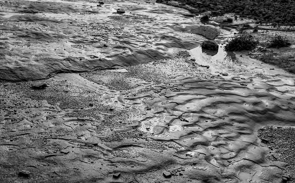
CHAPTER III TURBIDITE SYSTEMS: AN OUTCROP-BASED ANALYSIS 268
Fig. 282 - Eocene bedforms preserved in fluvial sandstones. Note megaripples with superimposed ripples that were migrating toward the viewer. Late-stage flood deposits in the Eocene Castissent Group, south-central Pyrenees. These features are sharply overlain by a mudstone unit which explains their exceptionally good preservation.
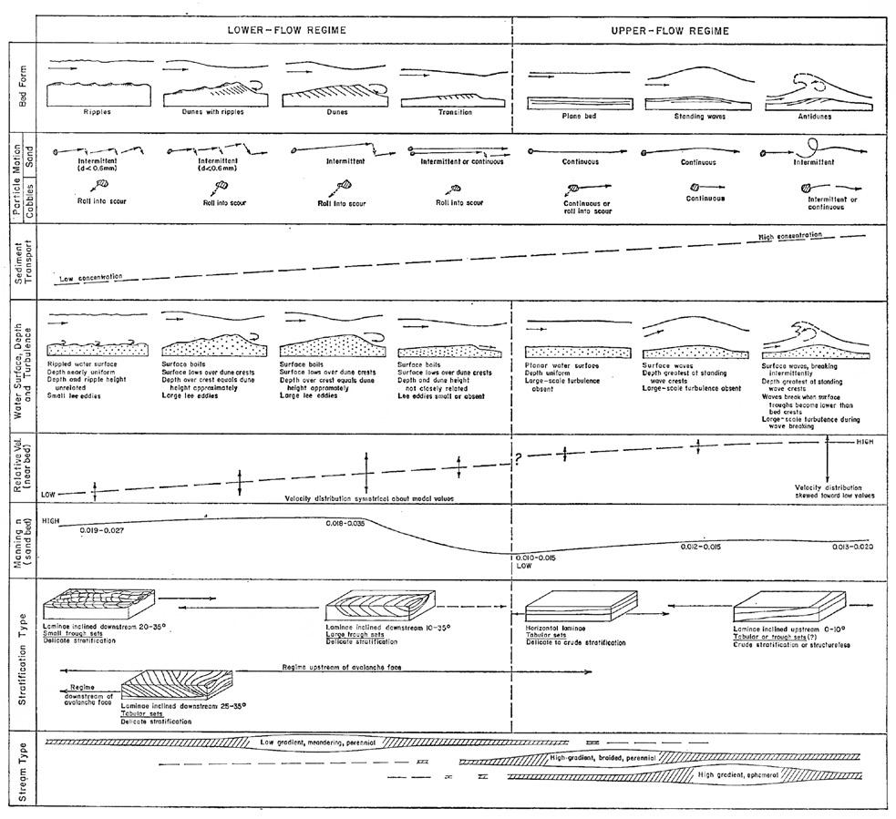
The transition between megaripple and plane bed configuration coincides with the transition between lower and upper flow regime; in the former, water surface is out-of-phase with the bedforms, whereas in the latter bedforms and water surface are in phase. It is generally agreed that the transition between lower and upper flow regime results from a change in the Froude number (Fr), i.e., roughly speaking a ratio between inertia and gravity forces, that separates subcritical flows (Fr <1) from supercritical flows (Fr > 1). For higher flow velocities, bedforms become progressively more complex giving way to standing waves, antidunes and other features (Figure 283), which were at that time somewhat overlooked in the assumption of their little preservation potential.
Figure 285 is a size-velocity diagram showing the stability field of the different bedforms. It will be noted that dunes (3D large ripples) and sandwaves (2D large ripples) do not form in fine-grained sediment, where, for increasing flow velocity, ripples are directly replaced by upper plane bed, but at lower velocity than in coarser-grained sand. The transition between lower and upper flow regime is still an open problem and largely depends on the interpretation of upper-plane bed laminae. The problem is amply discussed by Cheel (2005) who emphasizes how the transition may actually occur for Fr numbers ranging between 0.84 and 1 (Figure 286 A) and how washed-out dunes develop parallel laminae fitting into the lower flow regime (Figure 286 B).
CHAPTER III TURBIDITE SYSTEMS: AN OUTCROP-BASED ANALYSIS 269
Fig. 283 - Flow regime, bed forms, and resulting sedimentary structures (after Harms and Fahnestock, 1965).
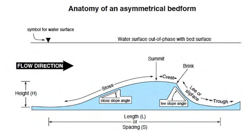
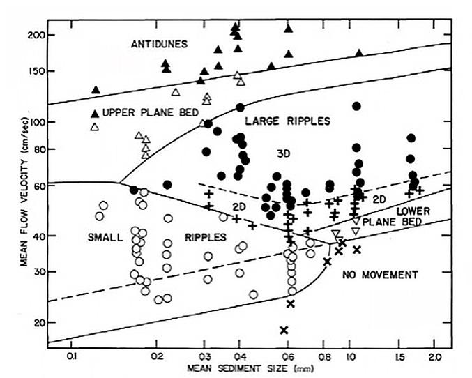
CHAPTER III TURBIDITE SYSTEMS: AN OUTCROP-BASED ANALYSIS 270
Fig. 284 - Elements and terminology of asymmetrical bedforms (ripples and megaripples) (from Cheel, 2005).
Fig. 285 - Size-velocity diagram showing the stability field of bedforms (flow depth of 18-22 cm; temperature of 10° C) (from Harms et al., 1982).
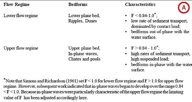
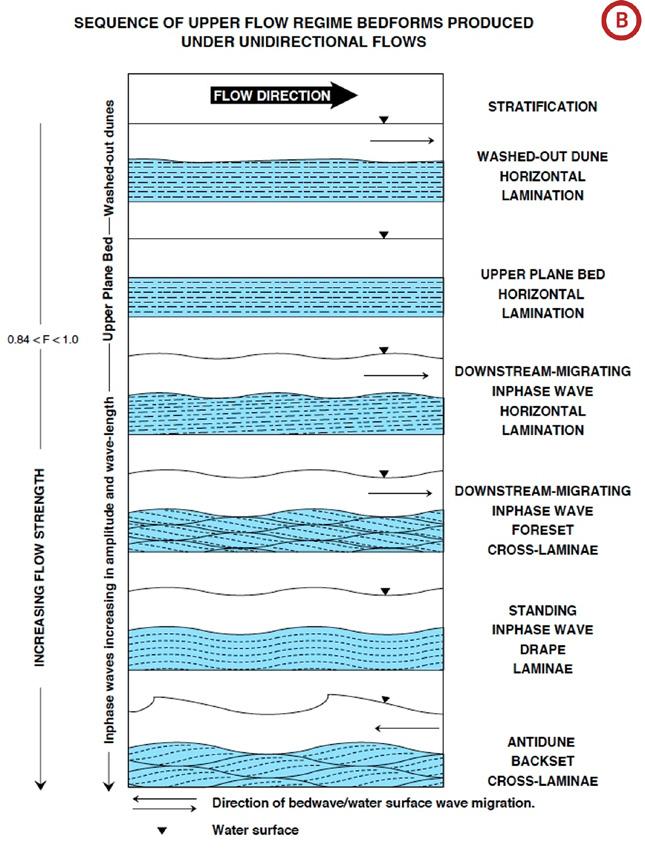
CHAPTER III TURBIDITE SYSTEMS:
271
AN OUTCROP-BASED ANALYSIS
A B
Fig. 286 - The problem of upper plane-bed laminae (A) as envisaged by Cheel (2005). Note that washed-out dunes would actually be lower flow regime bedforms (B).
It is also my opinion that upper plane bed horizontal laminae can form in both upper and lower flow regime. As discussed in turbidite facies (Chapter II), parallel laminae can be observed in F3 beds, an upper flow regime deposit, and their origin can be, in this case, related to the migration of low-amplitude bed forms; parallel laminae also occur in F5 beds, which are apparently the deposit of flows in the lower regime. The former is characterized by grain-size banding and form thin sets typically fining- and thinning-upward and bounded by broadly non-parallel surfaces; the latter are generally thinner and finer grained, display an abundance of surfaces loaded with mica and locally plant fragments (along which laminae can easily split), and are invariably associated with typical ripple laminae both vertically and laterally.
The main sedimentary structures produced by the migration of ripples, megaripples and plane beds are characteristic of relatively coarse-grained materi-
al (medium to coarse sand). Figure 287 shows how the cross strata geometry produced by ripples and megaripples is controlled by the plane-view geometry of ripple and megaripple crests. Straight-crested megaripples originate a type of cross strata referred to as tabular (or 2D) cross-bedding; sinuous crests originate festoon-type (or 3D) cross-bedding or trough cross-bedding. In both flume experiments and modern streams straight-crested megaripples (also referred to as sand waves) form for flow velocities slightly slower than those producing sinuous-crested megaripples (often referred to as dunes). The terms 2D and 3D dunes should probably be preferred to avoid terminology problems. Within each set, cross laminae can be angular, concave-upward, tangential or sigmoidal (convex-upward) (Figure 288). There is general consensus about angular, concave-upward and tangential laminae being the product of an increase in flow velocity; sigmoidal laminae are generally interpreted as indicating increasing rate of sediment fallout (see later).
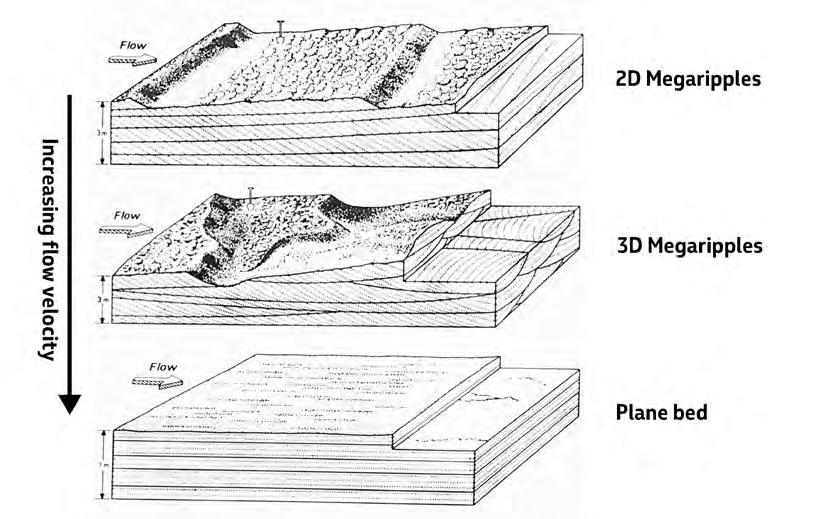
CHAPTER III TURBIDITE SYSTEMS: AN OUTCROP-BASED ANALYSIS 272
Fig. 287 - Internal structure of basic bedforms (after Harms et al., 1982).
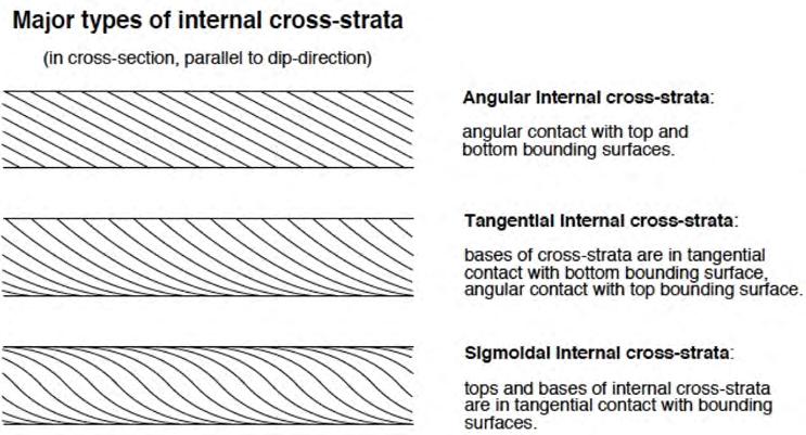
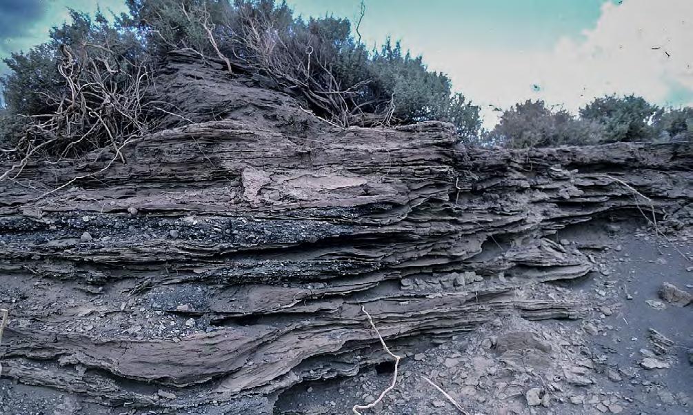
CHAPTER III TURBIDITE SYSTEMS: AN OUTCROP-BASED ANALYSIS 273
Fig. 288 - Geometry of cross-strata according to Cheel (2005).
Fig. 289 - Modern flood deposits showing fine-grained current laminated sands, with climbing ripples. Note small convex-upward lenses of small pebbles at the base of some flood units. Unrecorded ephemeral stream, Chubut province, Argentina.
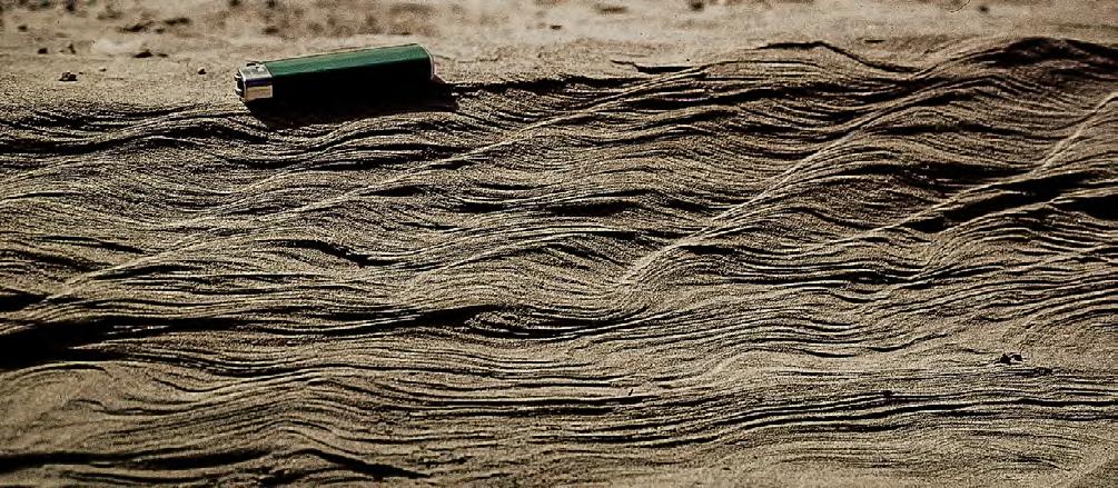
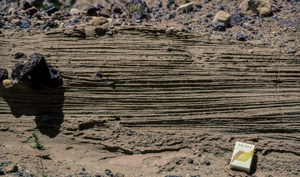
Much larger bedforms, which would be impossible to reproduce in laboratory experiments, develop in modern fluvial systems at a scale that dwarfs that of the Rio Grande structures. The monsoon-driven Brahmaputra and Ganges rivers drain an enormous land area and carry to the Bay of Bengal some 13 million tons of suspended sediment per day during flood. Coleman (1969) has shown that during maximum-flood periods
bedforms (giant dunes or sand bars) attain heights up to some 15 m and migrate downstream at rates as high as 600 m per day. During falling stage, these giant dunes become covered by smaller-scale features (trough-cross and upper plane bed laminae) and eventually by climbing ripples from suspended load (Bristow, 1993). Though from a giant river system as the Ganges-Brahmaputra system, these bed load features
CHAPTER III TURBIDITE SYSTEMS: AN OUTCROP-BASED ANALYSIS 274
A B
Fig. 290 - Examples of suspended load deposits in modern flood units (unrecorded streams, Patagonia, Argentina). A. Climbing ripples; B. Sets of parallel laminae separated by low-angle erosional surfaces (indicated by arrows).
seem very important in assessing the role of floods in a transfer zone (see later), since it is difficult to escape the conclusion that a substantial part of them must result from traction along the bed produced by the shearing imparted from bypassing turbulent flows loaded with fines. Through the Swatch of No Ground canyon, these flows actually bypass the shoreline and deposit huge amounts of fine-grained load in the similarly huge Bengal Fan.
IV.2.2 – Suspended load structures
Under normal conditions, particles smaller than say 125 microns have the tendency to move as suspended load, i.e., they are kept in suspension by the vertical component of turbulence eddies; once suspended, the particles move at a velocity which is about the average flow velocity. Turbid fluvial waters that are common after a heavy rain and with which we are all familiar exemplify the normal suspended load transport. No flume experiments have been performed concerning this type of transport and sedimentation, but deposits originated under such conditions are extremely common and easily observable in modern rivers and flood plains. (Figures 289-290).
Basically, this kind of deposits results from turbulent flows that during the waning stage lose their sediment load though progressive fallout from the suspension. Once reached the bed, individual particles undergo traction forming laminae that will be eventually buried
under new and finer-grained sediment falling out from the flow. The basic structures are those described by Jopling and Walker (1968) in their fundamental paper with examples from the deposits of density underflows of sediment–laden meltwater flowing into a glacial lake during the late Wisconsin near Concord, Massachusetts.
The process is generally referred to as “traction plus fallout” and its typical deposit is shown in Figure 291. Most beds formed under these conditions are characterized by a sharp basal contact, well-developed distribution grading (i.e., mean grain size decreases upward, i.e with time), and a vertical succession of laminasets that are highly diagnostic of this process. For decreasing flow velocity, increasing rates of fallout, and progressively smaller particles, a basal division of horizontal laminae is followed upward by ripple laminae indicating increasing preservation of stoss-side deposits and finally by climbing ripple and sinusoidal laminae. Climbing ripples are probably the most diagnostic feature of these beds (Figure 292). A division of structureless mudstone forms the uppermost part of the bed. Upward-decreasing thickness of individual parallel laminae as well as the decrease of tractional processes hampered by increasing particle cohesion in the ripple divisions are good evidence of this process. These deposits can hardly be distinguished from those of dilute and turbulent turbidity currents (see above) and, though originated from the suspended load of fluvial currents, can be regarded, for practical purposes, as a sort of “sediment gravity flow”.
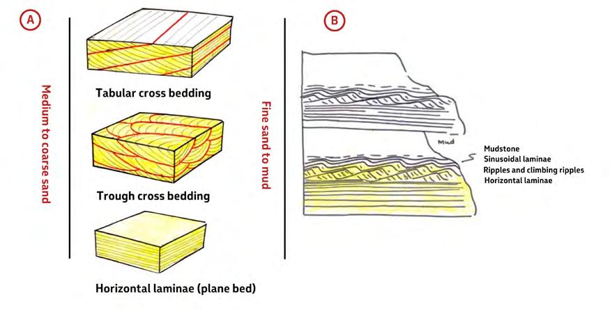
CHAPTER III TURBIDITE SYSTEMS: AN OUTCROP-BASED ANALYSIS 275
A B
Fig. 291 - Comparison of most diagnostic features produced by bedload traction (A) and traction-plus-fallout from suspended load (B).
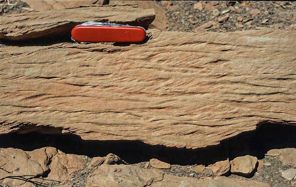
IV.3 - SOME REMARKS ON TROUGH CROSS-BEDDING, SIGMOIDAL BEDDING, AND SIGMOIDAL BARS
In most literature there is an abuse of the term “trough cross-stratification” (produced by the migration of 3D megaripples) without a correct appreciation of the external and internal geometry of the structure. The tendency is to equate cross-bedding with trough cross-bedding, overlooking the fact that there are many different kinds of cross bedding produced by migrating megaripples under conditions differing from those of unidirectional and steady fluvial currents (see above).
In this section we briefly review the problem of sigmoidal-shaped cross-bedded features which are important in both tidal and flood-dominated fluvial and fluvio-deltaic deposits. Their correct recognition is fundamental for facies analysis. In its most simple usage, the term “sigmoidal” refers to individual cross laminae with asymptotic terminations both upcurrent and downcurrent (Figure 288). The term has however been used to describe the geometry of beds and bedsets in both tidal and flood-dominated deposits raising problems as to terminology and origin of these features.
As acknowledged by De Rosa and Zuffa (1979), sigmoidal tidal bedding was first recognized in the Ager basin by Mutti and Rosell back in the mid 70’s and thought to be diagnostic of tidal processes. This kind of bedding was later formally introduced in the literature by Mutti et al. (1984) and Mutti et al, (1985) to describe sigmoidal beds and bedsets (Figure 293). A tidal sigmoidal bed consists of a set of medium-scale cross laminae which are sharply bounded above by a roughly flat erosional surface or, more commonly, by a thin horizontal division of current ripples resting on an erosional surface. The cross laminae become tangential downcurrent grading into flat-lying ripples and thin mudstone partings comprising the bottomset of the unit. These beds have thicknesses commonly on a decimeter scale and maximum length generally less than one meter. Tidal sigmoidal bedsets consist of lateral sequences of sigmoidal shaped cross-bedded sandstone units separated by finer-grained partings. These bedsets are typically bounded by a basal flat or gently downcurrent dipping surface and by an upper broadly convex-upward surface. When fully developed, sigmoidal bedsets, having lengths up to several meters, consist of individual sigmoidal beds arranged in lateral sequences showing an initial stage of downcurrent thickening that,
CHAPTER III TURBIDITE SYSTEMS: AN OUTCROP-BASED ANALYSIS 276
Fig. 292 - Example of low-angle climbing ripples. Cretaceous Rayoso Group, Neuquén basin.
after reaching a peak, is replaced by a gradual thinning and flattening of each bed. Based on data from modern and recent tidal deposits offered by Visser (1980) and Boersma and Terwindt (1981) in two fundamental papers, it appears that this kind of sedimentation is related to tidal cyclicity, essentially to the alternation of strong and weak tidal currents with time (Figure 294). In the case of neap-spring-neap cycles each tide produces a sigmoidal bed (dominant tide) and an associated mud couplet (slack water and subordinate tide). For longer period tidal cycles, perhaps related to equinox phases, each sigmoidal bed is a composite bed recording an entire lunar cycle. The analysis of mud couplets generally permits the distinction. (Figures 295-296)
Tidal sigmoidal beds and bedsets are clearly features indicating upward terminations produced by truncation of bedforms of more complex and still poorly understood origin. In some cases, sigmoidal bedsets are preserved as thin remnants of their original configuration (Figure 296). The process is likely to be an erosion produced by subsequent lower-strength tidal currents that, following tidal cycles of longer periods, removed and transferred downflow the sand of the original upper portions of these features. For decreasing strength of tidal currents with depth, sigmoidal bedsets become thinner and very broadly lenticular in most subtidal environments (Figure 297).
The term sigmoidal has also been used by Mutti et al. (1994,1996, 2000) and Tinterri (2007, 2011) to describe
features associated with fluvial and fluvio-deltaic systems dominated by fluvial floods and related hyperpycnal flows. The term sigmoidal has been used to refer to a particular type of facies commonly observed in flood-dominated river mouth-bar deposits (sigmoidal bedding), and to sigmoidal bars produced by flash floods. In the first case (Figure 298), amply discussed and compared with tidal bedding by Tinterri (2011) (Figure 299), sigmoidal units form as tractional features when sediment-laden streamflows enter seawater, drop and tract their excess sediment and keep moving seaward as turbulent hyperpycnal flows carrying most of their sediment as suspended load. Basically, these sigmoidal cross strata move seaward impelled by the shear stress of an overlying turbulent flow. From a geometric standpoint, these beds bear many similarities with tidal sigmoidal bedding in that also in this case internally cross-bedded sigmoidal units most commonly form lateral sequences thinning in a downcurrent direction. These units are bounded below by a sharp surface in their upcurrent portions grading downcurrent into a transitional contact; the upper boundary can be a flat horizontal or gently downcurrent dipping erosional surface or a drape of finer-grained and laminated sediment resting upon truncated or sigmoidal cross laminae. The lateral sequence of sigmoidal units as well as their downcurrent thinning can be easily explained by the gradual decrease in strength and the pulsating character of the incoming flow (see later).
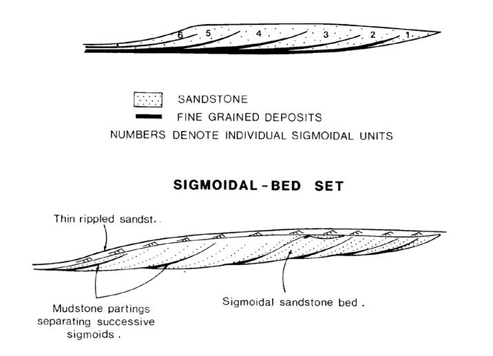
CHAPTER III TURBIDITE SYSTEMS: AN OUTCROP-BASED ANALYSIS 277
Fig. 293 - Original definition of tidal sigmoidal bedding (Mutti et al., 1985).
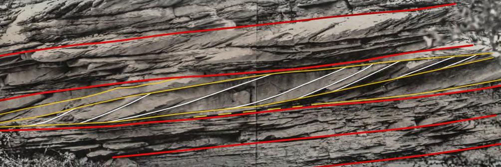
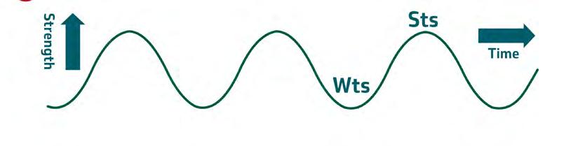
The sigmoidal bars consist of meter-scale sigmoidal shaped bodies bounded upcurrent by a deep basal scour filled in with cross-stratified conglomerates grading upward and downcurrent into progressively finer-grained and laterally continuous sediments (Figure 300). Typically, these finer-grained deposits show a vertical transition from angular or concave-upward cross laminae into sinusoidal laminae that drape the entire unit. These units have been interpreted to record flash flood deposits following a hydraulic jump (Mutti et al., 1996). Tractive processes dominate the upstream termination of these bars, being gradually replaced downstream by suspended-load features. Depending upon the degree of flow efficiency, suspended load can be deposited at different distances from the coarse-grained expression of the sigmoidal bar (see Figure 300). As discussed later, also these bars are essentially an expression of sigmoidal bedding. Clearly, careful inspection of fluvial sigmoidal bedding and sigmoidal bars rule out any possible doubt about a tidal origin, though in the cases of outcrops of limited extent and without knowledge of the context, the distinction may be difficult.
Because of their importance, flood-generated cross-bedding, sigmoidal features and their interpretation are amply discussed in the following sections dealing with depositional elements and their component facies.
IV.4 - THE PROBLEM OF FLOW CRITICALITY
For many years, the models developed for bed load and suspended load structures and their formative processes discussed above have been widely accepted, thus forming the basis for the hydrodynamic interpretation of fluvial sediments and their internal structures. In particular, these models focussed on bed load transport without substantial sediment addition from above and ensuing aggradation. Supercritical flows and their structures were thought to be essentially very rare because of their poor preservation potential. The only structure assigned to an upper flow regime and therefore to a supercritical flow remained for long time the parallel lamination found at the base of many ripple divisions in fine to very fine-grained sandstone beds transported by rivers as suspended load.
CHAPTER III TURBIDITE SYSTEMS: AN OUTCROP-BASED ANALYSIS 278 A B
Sts
Fig. 294 - Typical tidal sigmoidal bedding. Red lines indicate master surfaces produced by vertical accretion; yellow lines are boundaries of sigmoidal bedsets; white lines define individual sigmoidal beds. From right to left, blue lines and arrows indicate first thickening then thinning of individual sigmoidal beds. Wts: weak tides; Sts: strong tides. Eocene Figols Group, near Ager, south-central Pyrenees. Cyclic variation of tidal current strength with time. Periodicity can be related to neap-spring cycles, equinoctial cycles or longer period cycles.
Wts
Wts
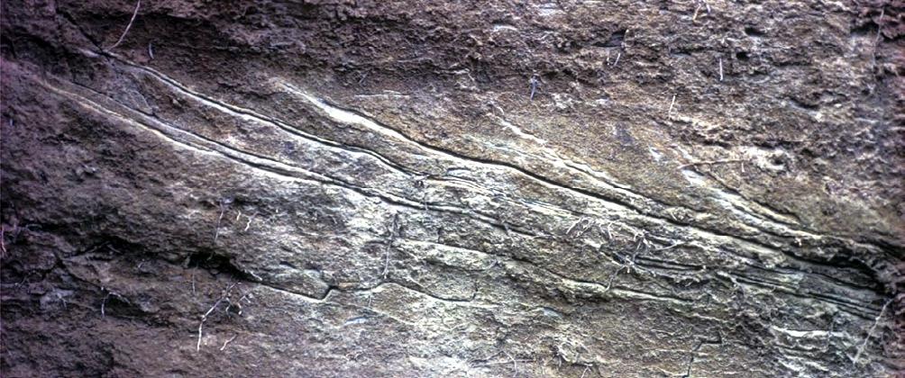
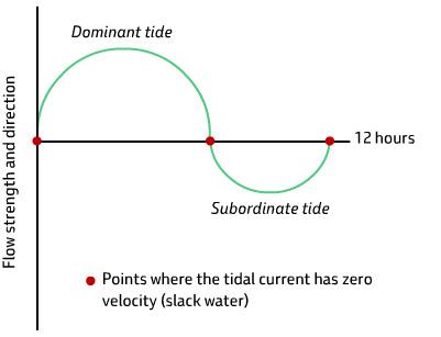
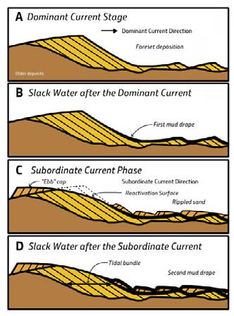
CHAPTER III TURBIDITE SYSTEMS: AN OUTCROP-BASED ANALYSIS 279 A B C
Fig. 295 - Example of mud couplets, Eocene Figols Group, south-central Pyrenees (above) and their origin as related to tidal cycles. The insert in lower left is from Darlymple (2010) (based on Visser, 1980).
Mud couplet
R
MC
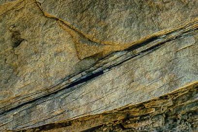
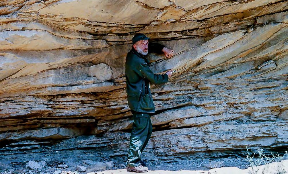
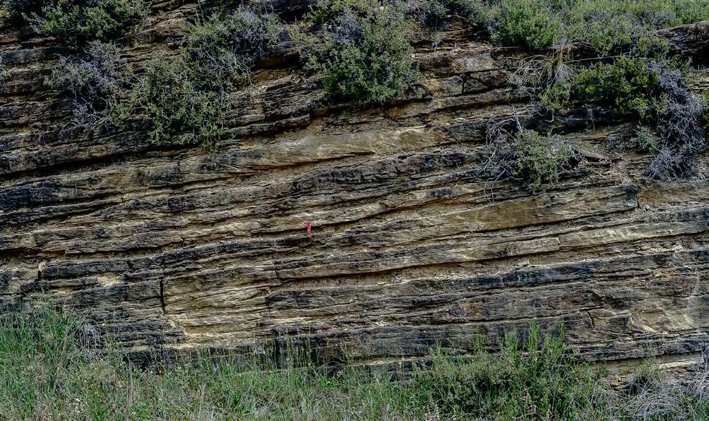
CHAPTER III TURBIDITE SYSTEMS: AN OUTCROP-BASED ANALYSIS 280
Sigmoidal bedset WTs STs
Fig. 296 - Downcurrent migrating sandstone sigmoids (produced by strong tidal currents, STs) separated by muddier partings (produced by weaker tidal currents, WTs). Mudstone couplet (MC) analysis shows that at least one neap-spring cycle is contained within each sandstone sigmoid, thus suggesting longer period tidal cycles, perhaps related to equinox phases. Note erosional remnants of sigmoidal bedsets (R).
Eocene Figols Group, south-central Pyrenees, Spain.
Fig. 297 - Subtidal sigmoidal bedding. Note the broadly lenticular geometry of sigmoidal bedsets. Dominant tidal currents toward the right. Eocene Figols Group, near Ager, south-central Pyrenees.
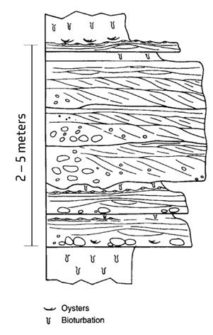
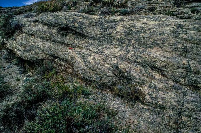
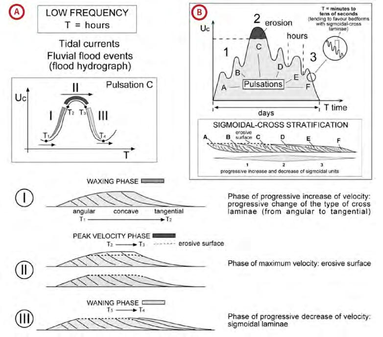
CHAPTER III TURBIDITE SYSTEMS: AN OUTCROP-BASED ANALYSIS 281
Fig. 298 - Example of sigmoidal bedding in river-mouth bar deposits overlying shelfal sandstone lobes with hummocky cross stratification. Eocene Figols Group, south-central Pyrenees, Spain (from Mutti et al., 2000).
A B
Fig. 299 - Comparison of processes controlling the development of a tidal sigmoid, i.e. the product of one dominant tide (A) and floodgenerated sigmoidal bedding produced by a single flood event through its pulsations. From Tinterri (2011).
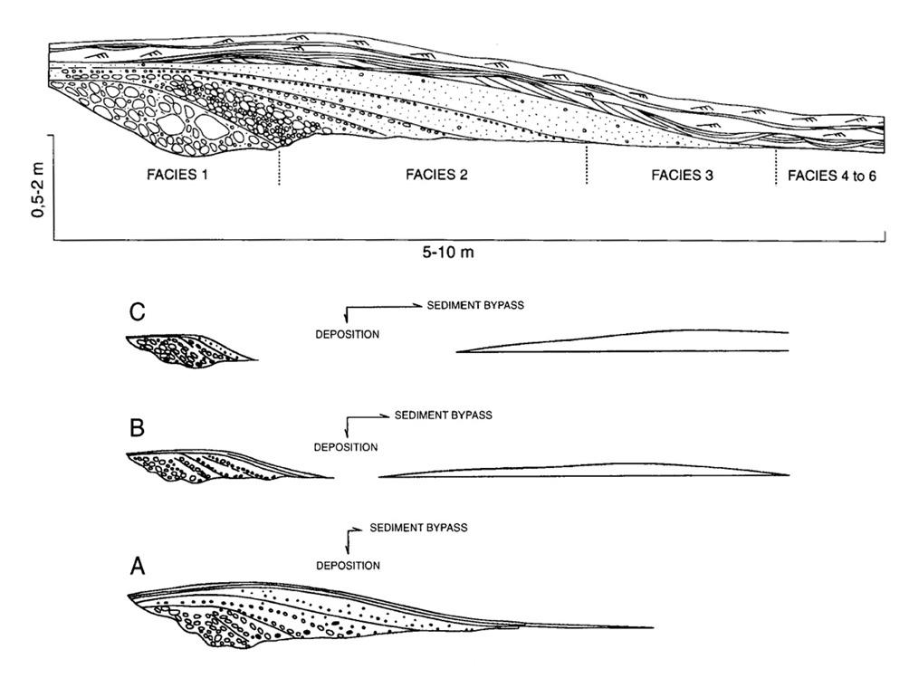
As amply discussed in Chapter II, growing evidence indicates that many turbidity currents are supercritical and can deposit part of their load from fast-moving, powerful suspensions through a traction-plus-fallout mechanism very similar to that of the suspended load of “normal” fluvial floods. Similarly, several structures observed in coarse-grained (pebble- and coarse-grained sand-grade) seem likely to be the product of super-
crtitical flows moving as basal dense flows (Figure 301). Since most of the flows generated by fluvial floods are sediment gravity flows, it is here argued that many of these flows, especially if accelerated in high-gradient settings, should be supercritical. Therefore, supercritical sedimentary structures should also be present in alluvial and fluvio-deltaic deposits, though partly or entirely removed by subsequent subcritical processes.
CHAPTER III TURBIDITE SYSTEMS: AN OUTCROP-BASED ANALYSIS 282
Fig. 300 - Cross section of a sigmoidal bar in a cut parallel to the flow direction (above). Below, A, B and C show sediment distribution as a function of flow efficiency (after Mutti et al., 1996).
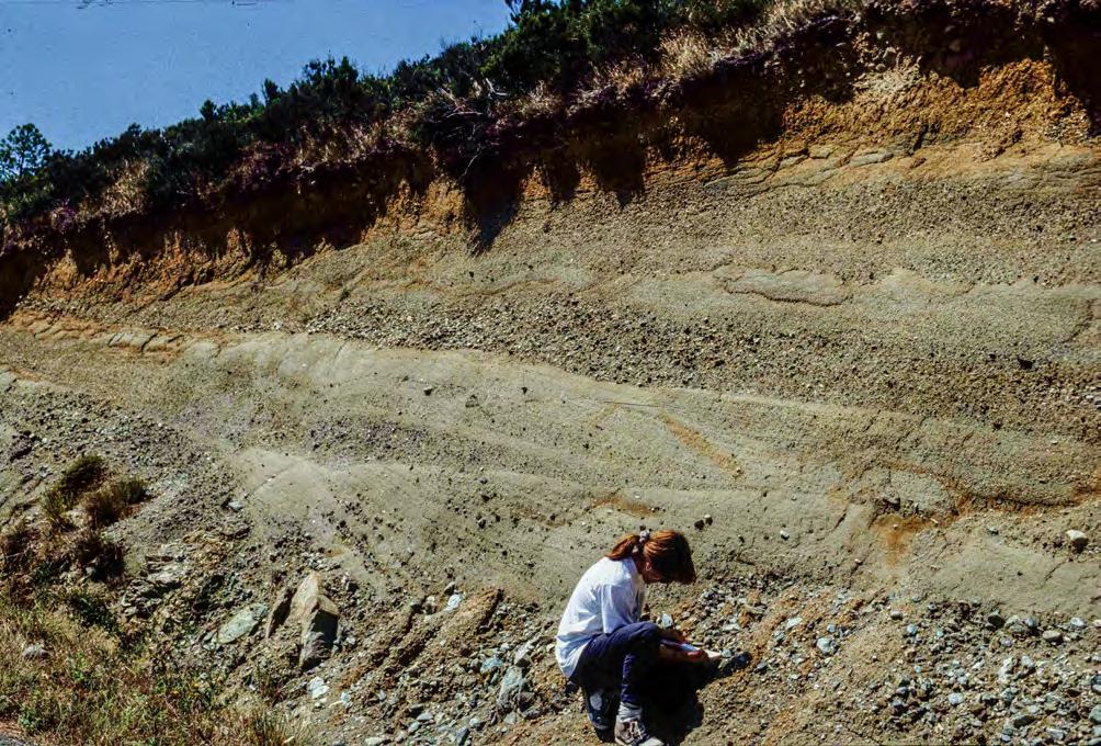
Fielding (2006) has emphasized that most of these features have probably gone unnoticed until now (though see early mentions in Roe, 1987, and Massari, 1996) and preliminarily suggested a scheme for their recognition, with bed configurations ranging from transitional dunes to chute-and-pools (Figure 302). Based on flume experiments, synthetic stratigraphy, numerical simulations, and limited discussion of examples from the ancient record, Cartigny et al. (2014) have also attempted to provide some insight into the
same problem (Figures 303-304). Thought very useful for a better understanding of the complex depositional patterns inherent to supercritical flows, obvious scale problems still make it difficult the practical application of these models to outcrop studies (see Chapter II). The same authors also provide a comparison of both field observations and flume experiments concerning these structures (Figure 305), from which the reader can realize how subjective the interpretations may still be.
CHAPTER III TURBIDITE SYSTEMS: AN OUTCROP-BASED ANALYSIS 283 BS
Fig. 301 - White lines define bedding surfaces of graded pebbly sandstone beds. These beds are underlain by a complex unit consisting of a basal unsorted debris flow deposit, containing pebbles, cobbles and angular boulders, overlain by pebble-filled scours (red lines) associated with banded sandstones and pebbles forming laminae dipping away from the scour. These features are thought to be the deposit of a supercritical flow through cyclic steps possibly promoted by bed roughness (boulders). Cross laminae indicated with BS could be the backset of a hydraulic jump. Brackish or lacustrine fandelta from the Oligocene Molare Group, Tertiary Piedmont Basin, northern Italy.
Only recently, some of these structures have been investigated in some more detailed outcrop studies, though restricted to glacigenic coarse-grained, Gilbert-type deltas (e.g., Lang et al., 2017). Nonetheless, mainly because of the general paucity of data and the lack of robust reference models, these structures are only marginally and tentatively dealt with hereafter
and briefly reconsidered in the conclusive sections. A very simple and recommended approach to their identification is a good knowledge of the “classic” sedimentary structures described in the mid sixties (see above). Departures from these features is a good reason to start thinking about supercritical flows and their products.
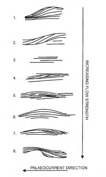
CHAPTER III TURBIDITE SYSTEMS: AN OUTCROP-BASED ANALYSIS 284
Fig. 302 - The model of Fielding (2006) . Spectrum of scale-independent internal depositional structures produced by supercritical flows. From 1 to 8, these structures indicate flows of increasing Froude number and vary from transitional dunes (1) to chute and pool (8) bed configuration, via plane bed and antidunes. See text and Figure 32 for more details.
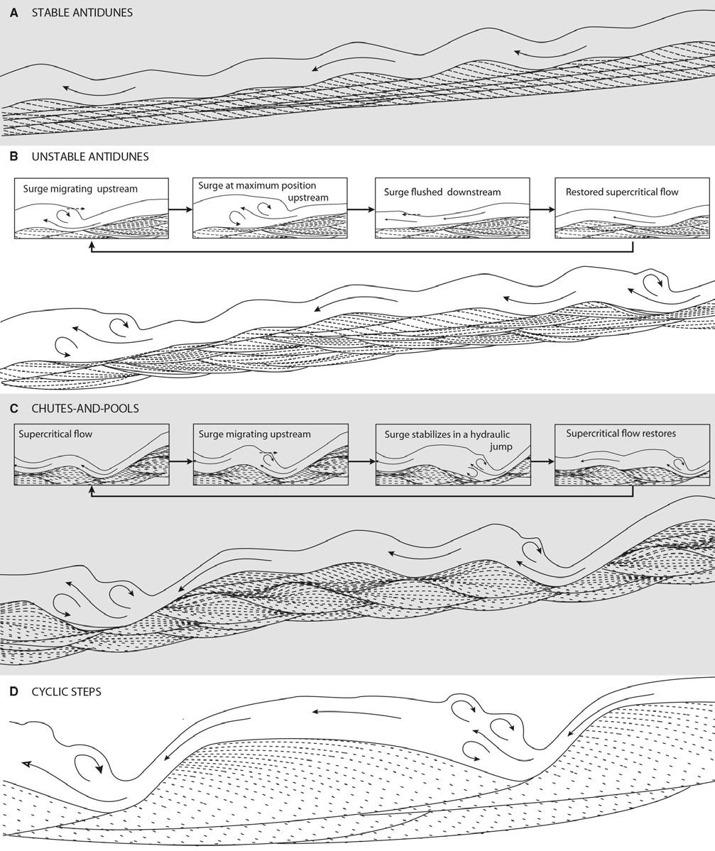
CHAPTER III TURBIDITE SYSTEMS: AN OUTCROP-BASED ANALYSIS 285
A B C D
Fig. 303 - The model of Cartigny et al. (2014). Summary diagram showing four kinds of bed configurations produced by supercritical flows and related erosional and depositional structures. Flow is toward left, and vertical scale is exaggerated. The scheme is based on data from flume experiments and synthetic aggradation. Flume was 12 m long. 0.48 m wide, and 0.6 m deep. From top to base and for increasing Fr number, the scheme shows the structures produced by stable antidunes (A), unstable or breaking antidunes (B), chutes-and-pools (C), and cyclic steps (D). B and C are characterized by highly complex bedding patterns.
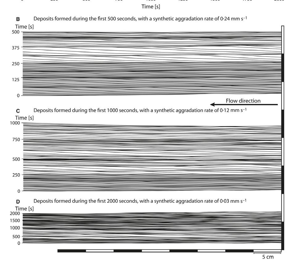
CHAPTER III TURBIDITE SYSTEMS: AN OUTCROP-BASED ANALYSIS 286
B C D
Fig. 304 - Chutes-and-pools structures obtained by flume experiments with increasing synthetic aggradation rates from base to top (from Cartigny et al., 2014). Scale would preclude their actual recognition in outcrop and core studies, where these structures would be mistaken, in most cases, for parallel laminae.
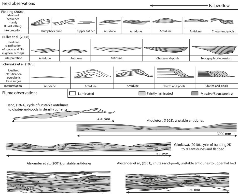
V - A TURNING POINT: ACTIVE MARGIN SEDIMENTATION AND THE IMPORTANCE OF “DIRTY RIVERS” IN DELTA FORMATION
In a breakthrough paper, Milliman and Syvitski (1992) made, for the first time, a clear distinction between the flux of fluvial sediment to the sea in divergent and collisional continental margins respectively. Based on the analysis of data from 280 rivers, the authors showed that “small mountainous rivers” (drainage basins < 10 000 km2), characteristic of tectonically active margins, have a previously underestimated sediment flux to the oceans favoured by high-elevation drainage basins, their proximity to the shoreline, high gradients, limited development of alluvial and coastal plains, and the general occurrence of narrow shelves. Such settings
are more prone to periodic floods and large amounts of sediment that may escape the narrow shelves to deeper basins. These small and medium-sized rivers therefore discharge large percentages of their sediment load directly to the sea through the combined effect of fluvial floods, slumps and turbidity currents also during high-stands of sea level. Conversely, the sediment flux of large rivers, almost invariably associated with divergent margins, has been largely overestimated since most of the sediment load is sequestered in extensive alluvial plains and deltas. According to these authors, small mountainous rivers do not form classic deltas, but should probably give way to coalescing small delta/fan deposits. This kind of sediments are thought by the authors to be rarely preserved in the stratigraphic record because subducted during the active margin evolution.
CHAPTER III TURBIDITE SYSTEMS: AN OUTCROP-BASED ANALYSIS 287
Fig. 305 - Suggested characteristics of supercritical flow structures compared from different sources (from Cartigny et al., 2014).
The scheme of Figure 306 attempts to summarize the main differences between divergent margins and tectonically active margins in terms of physiographic elements and types of sedimentation. For convenience, active margin sedimentation, which may occur in a variety of geodynamic settings, is here exemplified by a foreland basin. The scheme highlights some important implications as to sediment distribution patterns:
• In divergent margin settings, gravel is preferentially deposited in proximal alluvial fans and braided streams; sand and mud are partly deposited in fluvial transfer zones and associated alluvial plains and only the remaining sediment (sand and mud) can reach the sea. The initial sediment has thus been fractionated by size during its seaward motion by fluvial sorting and transient selective deposition. Sediment is essentially transported as bed load and suspended load by normal fluvial processes. Nonetheless, it should be kept in mind that large rivers may still carry large amounts of sand and mud to the sea. For an ideal grain of quartz originated in a drainage basin, the process is typically intermittent and requires a long time and different phases of transport and temporary deposition before the grain gets to the sea.
• In tectonically active settings, the above processes are shortened and take place over much shorter distances. Sediment fractioning basically occurs
within a single event generated by flooding in the drainage basin and, because of lack of extensive flood plains, only limited proportions of the original sediment volume is lost in transient depositional zones during flow motion. Rather, powerful, flood-generated flows are highly erosive and thus increase their concentration and momentum by eroding and resuspending transient deposition sediments encountered on the way down to the sea. As we will see later, the process continues also when these flows enter seawater.
• In divergent margins, upon reaching the sea sediment fractioning results from the complex interaction of marine diffusion processes (mainly waves and tides) and the fluvial processes that basically end at the exit of fluvial distributary. Conversely, in tectonically active settings sediment fractioning results from a sudden lost of excess sediment at the shoreline and, if the flows maintain sufficient momentum to escape the shorezone, from a progressive sediment fining in a seaward direction because of flow deceleration forced by friction and deposition. Depending on basin physiography, flows can deposit their load on shelfal regions or move directly to deep waters to form turbidite systems. In both cases, sedimentation will occur at depth well below wave base, thus forming deposits with a high preservation potential.
Alluvial & Coastal Plain Shoreline Sealevel
- Extensive alluvial and coastal plains incised by mature rivers
- Great distance from mountain front and shoreline Transient
- Transient depositional zones sequester large proportions of sediment
- Very long time involved for source-to-sink process
Foreland basin
Orogenic wedge
- High-elevation drainage basins close to shoreline
- High-gradient fluvial systems
- Transient deposition reduced by short time of source-to-sink processes
- Floods dominate transport and sedimentation
Flexural Subsidence
CHAPTER III TURBIDITE SYSTEMS: AN OUTCROP-BASED ANALYSIS 288
Thermal Subsidence
A B
Fig. 306 - Divergent (A) and active (B) continental margin characteristics.
The above considerations form much of the conceptual framework most of the following pages are based upon. They should be kept in mind whenever problems of “sediment routing systems” – an all-encompassing and fascinating approach introduced by Allen (2017) –are considered. These problems are briefly re-emphasized in the concluding sections.
Mulder and Syvitski (1995) expand on the data and conclusions of Milliman and Syvitski (1992) and emphasize the role of marine hyperpycnal plumes, or hyperpycnal flows, generated by floods. A hyperpycnal flow is defined as “a negatively buoyant plume that flows along the basin floor due to plume density in excess of ambient density of the standing water body, as a result of the sediment load that it carries” (op. cit., p.285) – basically a refined definition of the Bates (1953)’s concept (see above). The flow is a particular kind of turbidity current (fine-grained sediment fully supported by turbulence) occurring at a river mouth when the concentration of suspended sediment
is large enough to overcome the density of ambient water. In a fresh-water lake the sediment concentration needed to produce a hyperpycnal flow is quite low (< 1 kg/m3); in seawater a minimum concentration of 35-45 kg/m3 is required. Based on the analysis of 150 rivers, the authors conclude that only 9 modern rivers can trigger a significant number of underflows during one or more periods of the year (Table I). Except for the Huanghe River (the Yellow River), the remainder rivers have small mountainous drainage basins with low annual discharge. Only one river, namely the Haile River, China, flows into the sea with sediment concentration sufficient to develop hyperpycnal flows all over the year. Most of these rivers can be defined as small to medium sized rivers and have been termed “dirty” rivers by the same authors. The paper also discusses the possibility of generating occasional hyperpycnal flows for many other cleaner rivers, though ruling out the same possibility for the largest rivers of the world because of their insufficient sediment concentration when entering seawater.
CHAPTER III TURBIDITE SYSTEMS: AN OUTCROP-BASED ANALYSIS 289
River Qsava (kg s -1) Qsavb (m3 s -1) Qsavc (kg m -3) Cc av d (kg m -3) Qflood e (m3 s -1) High mountain (>3000 m) Choshui (Taiwan) 2000 190 10.5 38,917900 Mountain (1000-3000 m) Djer (Algeria) 20 2 13,442,77170 Tsengwen (Taiwan) 980 76 12,938,912100 Isser (Algeria) 190 12 15,442,718800 Rioni (Rusia) 110 5 20,743,528700 Daling (China) 1140 38 36,042,732300 Haile (China) 2570 63 40,542,740100 Huanghe (China) 34900 1880 18,542,756300 Upland (500-1000 m) Erhian (Taiwan) 400 16 25,538,96780
Table I - Dirty rivers that produce frequent hyperpycnal flows (from Mulder and Syvitski, 1995). a – average suspended sediment load; b – average discharge; c –average suspended sediment concentration; d –critical sediment concentration to trigger a hyperpycnal flow; e – maximum possible
VI - ANCIENT FLOOD-DOMINATED FLUVIO-DELTAIC SYSTEMS OF OROGENIC BELT BASINS AND THE ROLE OF HYPERPYCNAL FLOWS
As shown by Mutti et al. (1996, 2000, 2003), the great majority of alluvial and fluvio-deltaic systems of exposed orogenic belt basin fills can hardly be described by current sedimentological models, being instead dominantly made up of sediments transported and deposited by sediment gravity flows. The origin of such flows can only be explained through processes related to floods. Using examples from many different basins (Figure 307), these authors showed for the first time that (1) active-margin fluvio-deltaic sediments can be preserved in favourable geodynamic settings, despite the different opinion of Milliman and Syvitski (1992) (see above); (2) hyperpycnal-flow deposition also includes coarse-grained sediment (“bed load” of some usage) and not only finer-grained suspended load as suggested by Mulder and Syvitski (1993), thus raising new problems about processes; and that (3) unsuspectedly high degrees of catastrophism, much higher than that observable in some modern “dirty” rivers, have to be considered to explain sedimentation of the facies observed. For some reasons, the stratigraphic record indicates that during certain periods of time catastrophic processes became almost the normal processes governing sedimentation, thus casting serious doubts on the general validity of depositional models derived from modern processes and their facies (see Chapter I).
Mutti et al. (1996, 2000) introduced the term “flooddominated fluvio-deltaic systems” to denote small and medium-sized depositional systems of orogenic belt basin fills predominantly made up of flood units in both their alluvial and marine elements. These units, each being deposited by an individual flood event and thus being a bed, range from thick-bedded, internally unstratified mud- or clast-supported poorly sorted
conglomerates to thin-bedded graded siltstones and mudstones, via a great number of pebbly-sandstone and sandstone facies. Despite the great variety of depositional systems encountered, the authors recognized two intergradational end members of fluvio-deltaic sedimentation, namely (1) flood-dominated fan-deltas and (2) flood-dominated river deltas. As shown in Figure 308, both types of system have in common a depositional element made up of nearshore to shelfal tabular sandstone beds, with grading and hummocky cross stratification, interpreted as shelfal sandstone lobes deposited by hyperpycnal flows. In fan-delta systems, these lobes grade landward into and interfinger with an alluvial fan with its debris-flow and sheet-flow deposits; in river delta systems, they grade into mouth-bars formed at the exit of relatively stable distributary fluvial channels and associated lower delta-plain deposits. In both fan-delta and river delta systems, the lobe element grades seaward into prodeltaic and delta-slope, mudstones.
Though with some caution and reluctance, probably because of its catastrophic implications as opposed to the uniformitarian approach (see Chapter I), this kind of fluvio-deltaic sedimentation is slowly being accepted by the sedimentological community (e.g., Fielding et al., 2005; Bhattacharya 2006; Olariu et al., 2010; Gani and Bhattacharya, 2018) and even used to interpret some Mars rocks (Stack et al., 2019). However, though some models and numerous ancient examples have been recently offered for hyperpycnal flow deposition (e.g., Tinterri, 2011; Zavala et al., 2011; Zavala and Arcuri, 2016, Zavala and Pan, 2018), flood-dominated fluvio-deltaic systems still remain basically very poorly described and understood. Most importantly, no attempts have been actually made until now to understand the deposition of these flows in their upsystem expression, i.e., in the fluvial transfer zone. In the following sections an attempt is made to partly fill this serious gap.
CHAPTER III TURBIDITE SYSTEMS: AN OUTCROP-BASED ANALYSIS 290
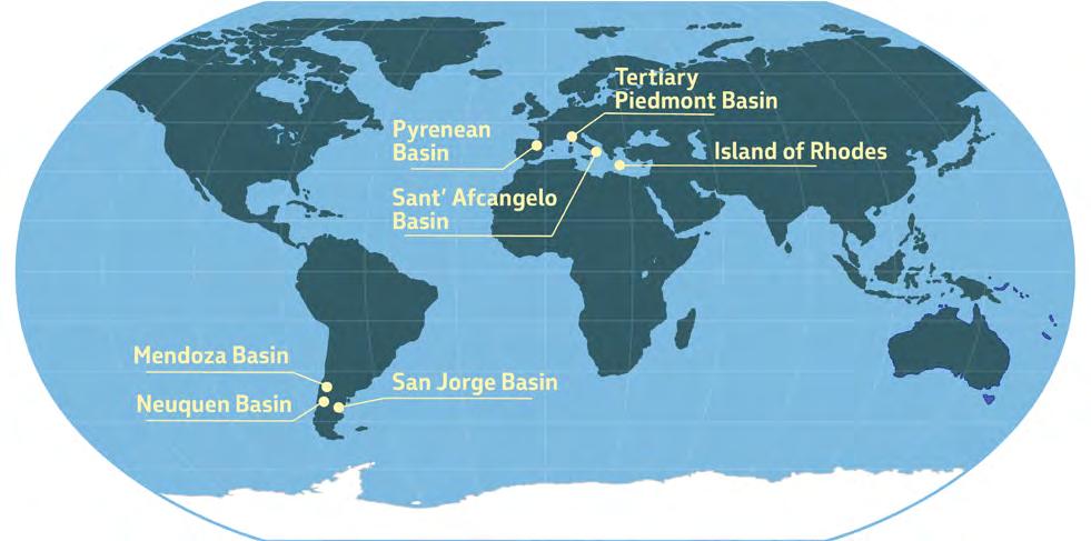
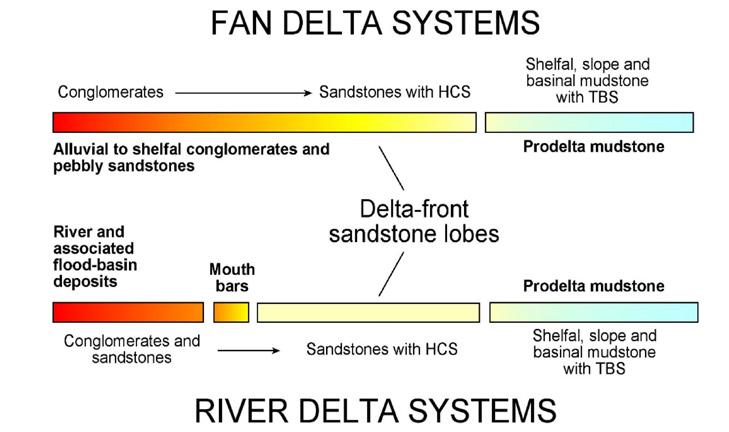
CHAPTER III TURBIDITE SYSTEMS: AN OUTCROP-BASED ANALYSIS 291
Fig. 307 - Location of the main study areas, with basin-fills from many different types of tectonically-active settings.
Fig. 308 - The main depositional elements of flood-dominated fan-delta and river-delta systems according to Mutti et al. (1996). Shelfal sandstone lobes (yellow) with hummocky-cross stratification (HCS), as well as their shelfal and slope muddier equivalents (green) are elements that are common to both types of system.
VII - WHAT DO WE REALLY KNOW ABOUT HYPERPYCNAL FLOWS?
Sedimentation related to hyperpycnal flows has given raise to a series of controversial opinions related to processes, types of deposit, and terminology. For these reasons, these problems are briefly reviewed below before discussing flood-dominated fluvial and fluvio-deltaic systems. For reasons of convenience and the sake of brevity, the discussion is limited primarily to fluvial floods entering seawaters.
VII.1 - HYPERPYCNAL FLOWS AND THEIR DEPOSITS
A hyperpycnal flow, as redefined by Mulder and Syvitski (1995) (see above), is a flood-generated, negatively buoyant fluvial plume that enters lakes or seawater and plunges at river mouth because of its excess density, thus becoming an underflow (Figure 309 A). The plume is a fully turbulent mixture of fresh water and relatively fine-grained particles (< medium sand) with a density in excess of 36-45 kg/m3; the plunging point is a zone of collapse and acceleration of the underflow (Lamb et al., 2010; see Figure 309 B). Hyperpycnal flows form seaward of the coastline at the mouth of small and medium size “dirty” rivers and are interpreted as relatively long-lived, quasi-steady flows sustained by the incoming fluvial flood; as such, they substantially differ from surge-type submarine gravity flows produced by sediment failure of finite volume. Based on the above characteristics, these flows can only deposit clay, silt and fine sand.

Plunging area
Hyperpycnites are the deposit of hyperpycnal flows (Mulder et al., 2002, 2003) and thought to be the deposit of a particular type of turbidity currents, i.e., sustained sediment gravity flows where the particles are entirely kept in suspension by the flow turbulence, but showing distinctive characteristics related to the original flood hydrograph (variations of discharge and sediment concentration with time). The typical beds produced by such hyperpycnal turbidity currents are shown in the scheme of Figure 310. The scheme is conceptually very elegant and describes the different types of hyperpycnal turbidites (hyperpycnites) as a function of flow magnitude (discharge). In particular, the scheme shows that inversely graded divisions (Ha) overlain by normally graded divisions (Hb) form for low- and mid-magnitude floods, and that Ha divisions can be removed by erosion in the case of high-magnitude floods. Stated in other words, Ha divisions record the rising stage of the flood hydrograph, whereas Hb divisions record flood peak followed by the falling limb. Unfortunately, the scheme is poorly supported by field data. Flood hydrographs can actually be reconstructed from the vertical sequence of sedimentary structures observed within beds, as for example in a recent fluvial bank (Figure 311) and in an ancient delta-front deposit (Figure 312). However, this kind of beds are quite rare in the ancient record and particularly in deep-water deposits (hyperpycnal turbidites), suggesting that Ha/Hb sequences are probably only rarely preserved mostly in proximal depositional regions but that Ha divisions are in most cases eroded and resuspended or bypassed during flood peak conditions.
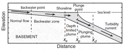
CHAPTER III TURBIDITE SYSTEMS: AN OUTCROP-BASED ANALYSIS 292
A B
Fig. 309 - A. Example of plunging plume in Lake Tanganyika (from Mulder et al., 2003). B. Scheme showing how a fluvial outflow of sufficient density becomes a plunging plume and a turbidity current (from Lamb et al., 2010).
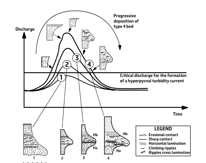
Falling limb
Flood peak
Rising limb
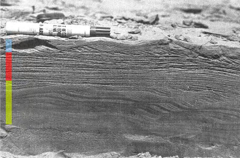
CHAPTER III TURBIDITE SYSTEMS: AN OUTCROP-BASED ANALYSIS 293
Fig. 310 - Types of bed produced by floods of different magnitude at river mouths according to Mulder et al. (2001). Explanation in the legend by the same authors. Beds 2, 3 and 4 are the deposit of hyperpycnal turbidity currents and should be termed hyperpycnites. See this text for comments.
Fig. 311 - Example of a modern flood unit with depositional divisions showing, from base to top, current ripples and sinusoidal laminae sharply overlain by parallel laminae, in turn overlain by ripples and sinusoidal laminae. The bed clearly records the rising limb (yellow), the peak (red), and the falling limb (blue) of the flood event. Unrecorded stream in the Neuquén region, Argentina.
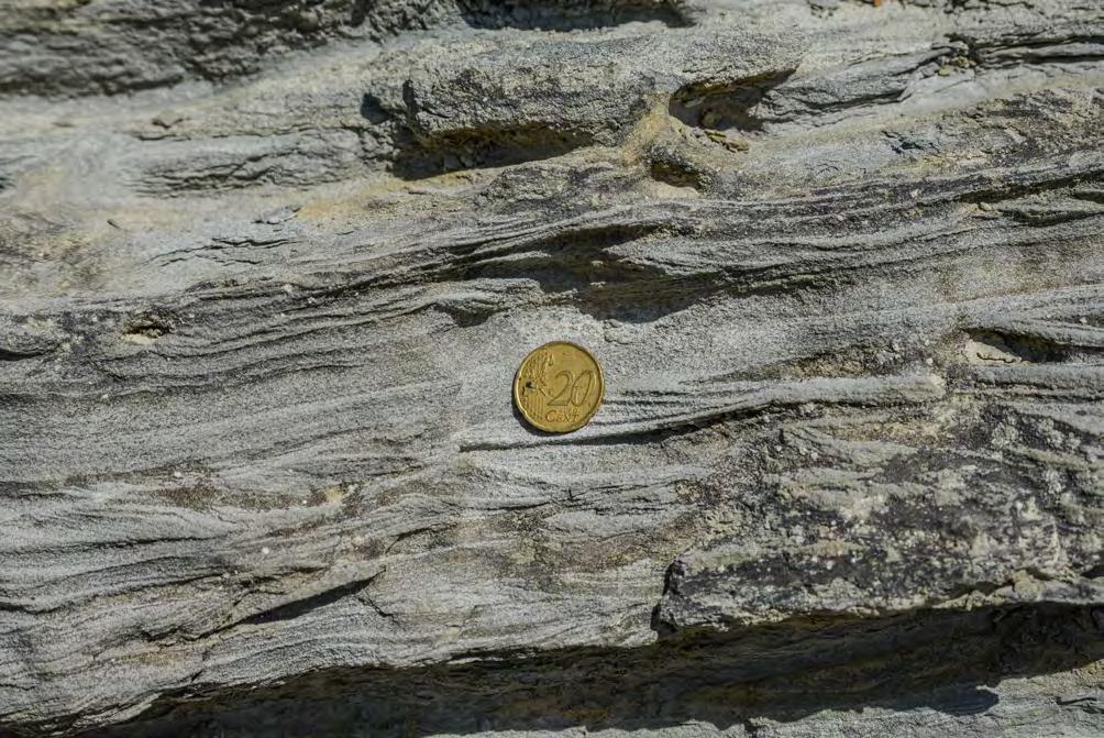
It is worth mentioning that hyperpycnal flows are ruled out as a possible process capable to deposit substantial amounts of sand on the shelf by both Talling (2014) and Shanmugam (2018). These authors conclude that hyperpycnites should be the deposit of feeble and muddy flows and made up of thin (< 10 cm) and finegrained beds. It should be noted, however, that both authors have ignored or overlooked in their conclusions all the previous literature on shelfal coarsegrained hyperpycnites.
Though supporting the hypothesis that hyperpycnal flows are a process that may ultimately end in deep-waters generating fluvio-turbidite systems (see Chapter I), Mutti et al. (1996, 2000) focussed their attention on the importance of hyperpycnal flows in
delta-front settings and flood-related flows in alluvial systems. These studies, based on a significant number of ancient deposits from orogenic belt basins (se above), leave no doubt that in flood-dominated fluvio-deltaic systems a considerable proportion of sediment carried to the shelf by hyperpycnal flows consists of coarse-grained sandstones, pebbly sandstones and conglomerates. It follows that a new definition of hyperpycnal flows to include dense river outflows seems to be necessary.
My suggestion, at present, is that hyperpycnal flows form a broad spectrum of density flows whose the two end members are coarse-grained dense flows (CGDFs) and turbulent plunging plumes (TPPs) (Figure 313). An almost endless series of transitional flows must operate
CHAPTER III TURBIDITE SYSTEMS: AN OUTCROP-BASED ANALYSIS 294
Falling limb
Flood peak
Rising limb
Fig. 312 - Flood hydrograph recorded in sandstone lobes of a flood-dominated fan delta. Note the truncation of the ripple division by the overlying parallel laminae of the flood peak. Oligocene-Miocene Stilo-Capo d’Orlando Formation, Calabria, southern Italy.
between the two end members, controlled by the characteristics of the fluvial system taken into consideration. Basically, CGDFs, which can vary from gravelly to sandy, dominate high-gradient settings, such as fan-deltas and coarse-grained deltas with limited development of alluvial plains. Typically, these flows carry substantial amounts of coarse-grained sediment as bedload. Conversely, TPPs dominate more mature and low-gradient settings where coarse-grained sediment is trapped in alluvial plains or in upstream fluvial reaches. The above conclusion appears to be a logical corollary of the model offered by Milliman and Syvitski (1992) (see above).
In the case of CGDFs of small and high-gradient systems, flood-generated subaerial flows probably behave like relatively short-lived surges, transferring to the sea their entire sediment load all at once through inertia-driven dense flows. By increasing the size of the system and the amount of fines, flows become
more complex and typically consist of three parts (Figure 314). The leading edge of the flow is most commonly a frictional debris flow followed by a bipartite flow consisting of a basal dense flow sheared by an overlying highly concentrated suspension; a more dilute and slower turbulent flow carrying fine sediment in suspension forms the trailing part of the flow. The scheme, inspired from the model envisaged by Sohn et al. (1999) (see Chapter II, Fig 95; see also Mutti et al., 2000, and Tinterri, 2007) implies deposition showing the downcurrent inversion of the deposits of the different parts of the flow (Figures 315 and 316). We concur with Sohn et al. (1999) that, except for the trailing dilute suspension, the frontal and the intermediate flows should be supercritical in most cases. Depending upon their volume, grain-size populations, and content in fines (controlling matrix strength), CGDFs can produce highly variable facies tracts.
Dense flow
Plunging plume
Shorezone
turbulent fluvial outflows loaded with fine sand and mud that plunge in the shorezone transforming into sustained, quasi-steady hyperpycnal flows. Most commonly, these flows can deposit only fine-grained sandstones and
CHAPTER III TURBIDITE SYSTEMS: AN OUTCROP-BASED ANALYSIS 295
A B
Fig. 313 - The two basic types of river outflows that can generate hyperpycnal flows. Dense flows (A) consist of gravelly and sandy flows driven by inertia forces under conditions of excess pore pressure that overcome density contrast with seawater and keep moving seaward. These flows deposit conglomerates graded pebbly sandstones and coarse to medium sandstones because of progressive freezing (mostly frictional) and deceleration with distance. Plunging plumes (B) are
mudstones.
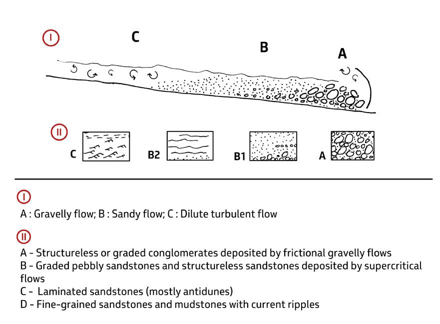
Parental flow (subaerial flow)
Flow transformation and bypass(channel exit)
Deposition (subaqueous flow)
Longitudinal grain-size gradient
CHAPTER III
SYSTEMS: AN OUTCROP-BASED ANALYSIS 296
TURBIDITE
Fig. 314 - Coarse grained dense flow (CGDF) and its deposits. See text for explanation.
Fig. 315 - The basic process of flood-generated flows entering fresh or sea water.
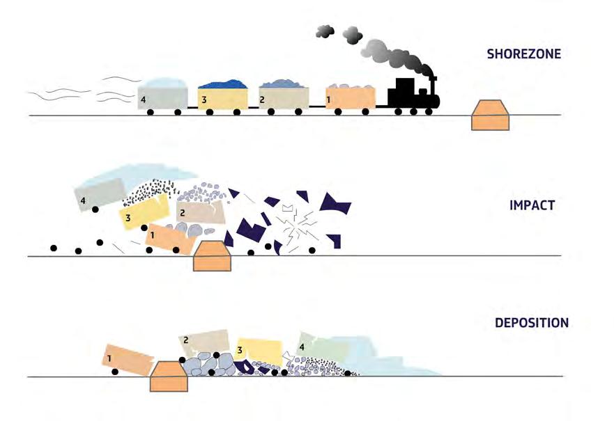
Very good examples of some of these facies are displayed by the fan-delta front deposits of the Silo-Capo d’Orlando Formation, southern Italy. These facies are illustrated in Figures 317-320 and briefly discussed hereafter. Figure 317 A shows structureless conglomerates with a sandy matrix deposited by frictional freezing of the head of the flow (part A of the flow); Figure 317 B shows the graded pebbly sandstone facies deposited by bipartite flows with a basal pebble carpet driven by inertia forces, probably in a liquefied state, and also impelled by an overlying supercritical suspension. The antidune laminae are very similar to the “thickly stratified pebbly sandstones” of Sohn et al. (1999, their Figure 11). Figure 318 shows a pebbly sandstone facies containing HCS-like laminae in the fine-grained divisions
deposited by a trailing and more dilute turbulent flow. Figure 319 shows a very good example of the complex internal structure of the pebbly sandstone facies with basal pebble carpets overlain by antidune bedforms recorded by thin alternations of small pebbles and sandstone. Figure 320 show the close association of structureless conglomerates and graded pebbly sandstones in a setting slightly more distal than that of the previous figures. Here, the pebbly sandstones consist of beds in which the basal conglomerate division either occurs as a coarse-grained structureless unit or as faint parallel laminae of alternating very small pebbles and sandstone. These sediments are further discussed in following sections dealing with alluvial fans and fan-delta front sandstone lobes.
CHAPTER III TURBIDITE SYSTEMS: AN OUTCROP-BASED ANALYSIS 297
Fig. 316 - Cartoon showing a dense coarse-grained flow entering seawater.
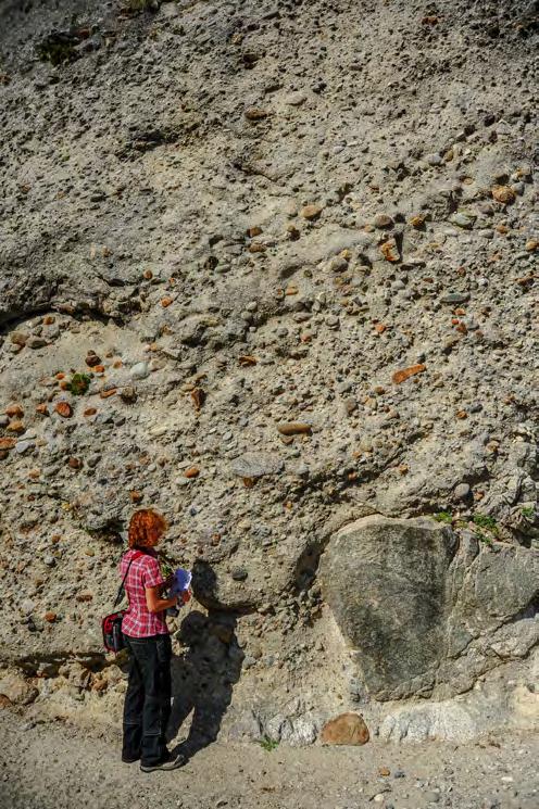
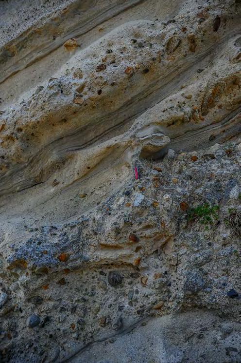
In the case of TPPs, turbulent sediment-laden streamflows can transfer to the sea large amounts of mud and sand as suspended load through a long-lived process (days, weeks and even months in the case of floods generated by monsoon rains, see Mulder et al., 2003). Entering seawater, these streams plunge to form a negatively buoyant plume that moves basinward as a sustained quasi-steady hyperpycnal flow. It should however be clear that all flood-generated subaerial flows must form plumes when entering seawater since the presence of some fine-grained
suspended load is a general characteristic of rivers in flood. Therefore, this kind of plumes is also present in settings dominated by CGDFs and become dominant if dense flows do not have sufficient momentum to overcome friction at the shoreline and are thus forced to deposit their coarser sediment when entering seawater. Similarly, some bed load is present in many settings dominated by plunging plumes, probably dropped by the plume at river mouth and its plunging point or incorporated by the flow through initial bed erosion.
CHAPTER III TURBIDITE SYSTEMS: AN OUTCROP-BASED ANALYSIS 298
A B
Fig. 317 - A. Structureless poorly sorted conglomerate with sandy matrix (note boulder at the base); B. Graded pebbly sandstones. Antidune laminae (with small pebbles) indicated by arrows. Antidune laminae are overlain by laminated fine sandstone with plant fragments (dark) deposited by the trailing turbulent flow.
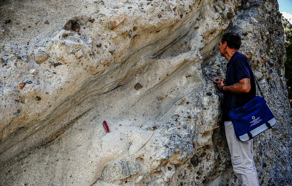
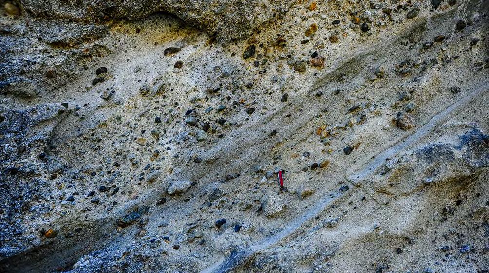
CHAPTER III TURBIDITE SYSTEMS: AN OUTCROP-BASED ANALYSIS 299
Fig. 318 - Conglomerates and graded pebbly sandstones. Note HCS-like laminae (yellow arrows) in the finer-grained divisions.
print NG IG
Fig. 319 - Graded pebbly sandstones with antidune laminae (yellow arrows). Note how a normally graded (NG) pebble division changes into an inversely graded (IG) division in less than one meter.
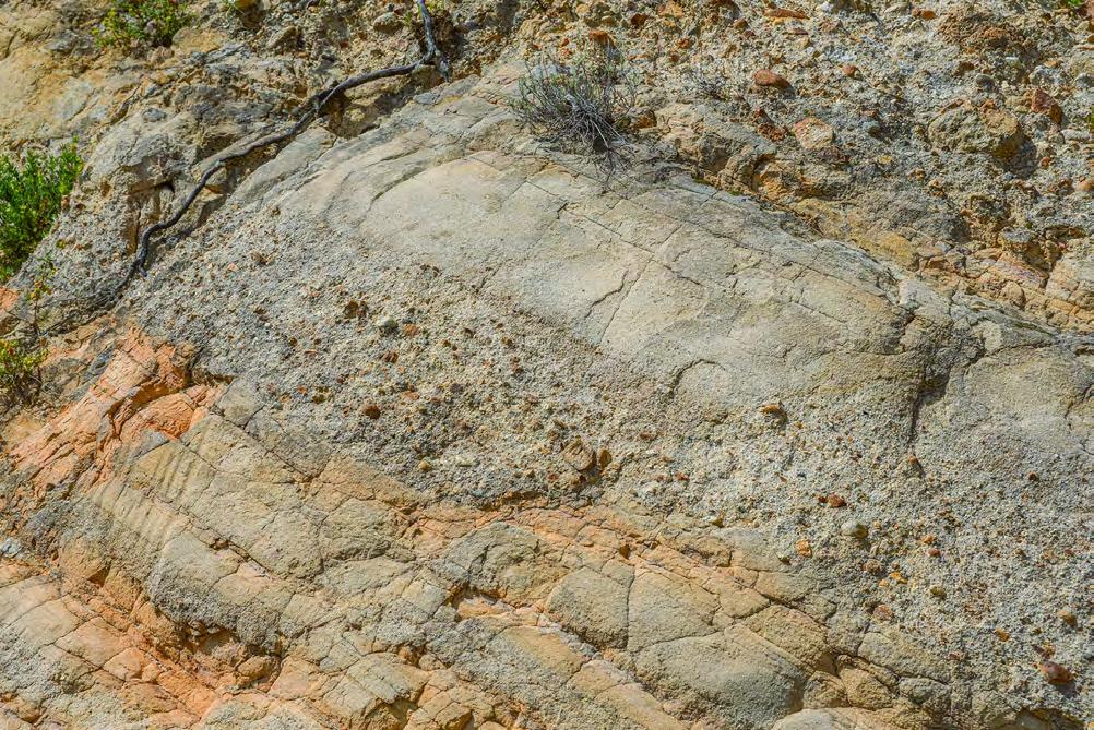
The problems discussed above remind me very much of the many controversies about turbidity currents, their deposits, and related terminology. Most of us are aware of the complexity of those flows that Kuenen and Migliorini (1950) first described as turbidity currents and are similarly aware of the complexity of their sediments. If we look at individual beds and consider all the different possible processes that we can infer from our field observations, flume experiments, monitoring of modern flows, and theoretical considerations, we would end up with a very confusing picture and an ever-changing terminolo-
gy (see Chapter II). Like turbidity currents and turbidites, hyperpycnal flows and hyperpycinites are terms representing a fair compromise to describe processes and sediments that are in fact inherently very complex and poorly understood. For these reasons attempts to frame these processes and sediments into rigid schemes of nomenclature and classifications appear somewhat premature at present. I will probably be insulting your intelligence by showing what you can learn about dense and turbulent flows by looking carefully at what happens in nature under your feet (Figure 321).
CHAPTER III TURBIDITE SYSTEMS: AN OUTCROP-BASED ANALYSIS 300
Fig. 320 - Association of structureless conglomerates (SLCGL) and graded pebbly sandstones. Note the thin laminae (yellow arrow) of alternating very small pebbles and sandstone. See text.
SLCGL Fault
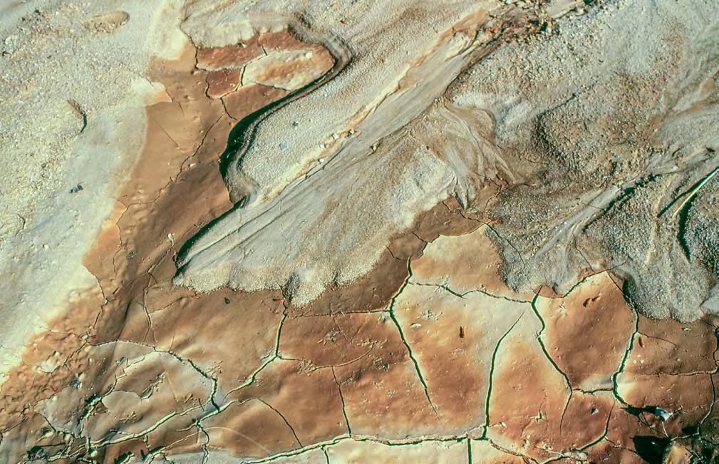
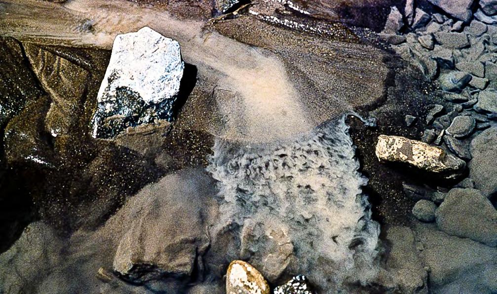
CHAPTER III TURBIDITE SYSTEMS: AN OUTCROP-BASED ANALYSIS 301
A B
Fig. 321 - Unexpensive experiments on dense and turbulent flows by looking carefully at what happens under your feet. A– Small delta observed after a heavy rain. Tracks of small birds for scale. Note the abrupt and lobate termination of the dense flow deposit. Mud cracks and bird tracks on the reddish siltstone deposited by the trailing turbulent flow. B – Very small delta forming on the bank of small river. Note the lobate shape and abrupt termination of the dense flow deposit and the plunging of the trailing turbulent flow in the delta slope.
VII.2 - TURBIDITES, HYPERPYCNITES AND PLUMITES
A further problem is that raised by hypopycnal flows, i.e., the dilute fluvial surface plumes propagating seaward (see above). Work by Parson et al. (2001) and Mulder et al. (2003) on flume experiments and, more recently, by Hizzett et al. (2017) through a detailed time-lapse monitoring of the Squamish Delta in British Columbia, Canada, has highlighted the previously overlooked importance of these flows in generating turbidity currents. These new observations have led to conclude that the dilute surface plumes exiting river mouths and floating on and propagating in seawater can dominate in some cases the triggering of turbidity currents, rather than submarine slope failures or dense plunging plumes. Through diffusive convection processes, at sediment concentrations as low a 1kg/cubic meter, these plumes give way to sediment layers with a density sufficient to sink and generate a hyperpycnal flow (Figure 322). If the dense bottom-riding layer can further increase its density by bed erosion, the
flow undergoes acceleration and a turbidity current, or a “plume-triggered event” as termed by Hizzett et al. (2017), is ignited. Obviously, the process is limited to fine-grained sediment (< medium sand), which is that originally transported as suspended load by plunging hyperpycnal plumes and dllute hypopycnal plumes.
Mutti (2019) has further expanded on this model and shown how most exposed “thin-bedded turbidites” can be explained in a similar way. Obviously, thin-bedded turbidites do exist especially as overbank deposits in inner and outer levees, as well as in distal basin plains and other specific settings (Mutti, 1977; Tinterri and Magalhaes, 2011). However, plume-triggered hyperpycnal turbidity currents as well as very dilute surface plumes not affected by diffusive convection processes can account for laterally extensive blankets of very thin to thin sandstone/mudstone couplets that drape coarser-grained turbidite sediments and cyclically alternate with them. Mutti (2019) has proposed that these plume-derived sediments be termed plumites
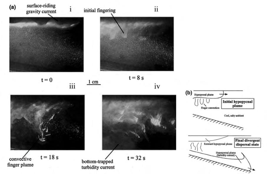
CHAPTER III TURBIDITE SYSTEMS: AN OUTCROP-BASED ANALYSIS 302
a b
Fig. 322 - Transformation of a hypopycnal plume into a hyperpycnal flow through diffusive convection processes as portrayed by experiments (a). Scheme summarizing the process (no scale involved) (b). Note finger-like features (After Parson et al., 2001).
Plumites are a very important group of deposits forming the natural link between fluvio-deltaic and delta-fed turbidite sedimentation. Being derived from dilute plumes characterized by low-sediment concentration – probably the most common expression of rivers in flood -, these sediments form blankets that extend from delta-front to slope and basinal regions, at distance from river mouths controlled by the volume of river outflows. In small and medium-sized orogenic belt basins, these blankets may be of virtually basin-wide extent. In particular, these sediments comprise the bulk of prodeltaic and delta-slope mudstone-dominated elements (see later). Their correct recognition requires excellent exposures allowing for detailed inspection of internal sedimentary structures. Most of these details are clearly visible in cores.
Basically, these sediments are thin- to very-thin siltstone/mudstone and sandstone/mudstone couplets forming three main types of facies (for more details see Mutti, 2019):
• Type 1 facies consists of very thin (mm-scale) beds with a lower division made of coarse siltstone forming mm-thick and laterally persistent parallel laminae or laminasets (Figures 323 and 324). These beds alternate with rarer and slightly thicker beds with a basal division made of small starved ripples, commonly with variable length and separated by intervening parallel laminae. Both kinds of bed show a sharp contact between the coarse-siltstone division and the overlying mudstone. The parallel laminae suggest direct deposition onto the bed from hypopycnal plumes with low sediment concentration and through differential settling imposed by the Stokes settling velocity. As suggested by the experiments of Parson et al. (2001), these plumes allow for discrete particle settling without being affected by convection processes. The starved ripples indicate some traction on the bottom probably produced by weak and turbulent flows in the absence of sufficient coarse silt fallout.
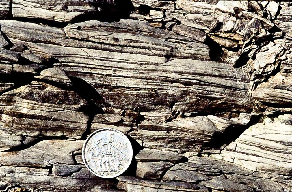
CHAPTER III TURBIDITE SYSTEMS: AN OUTCROP-BASED ANALYSIS 303
Fig. 323 - Type 1 facies. Very thin bedded siltstone/mudstone couplets. Siltstone forms mm-thick parallel laminae or slightly thicker starved ripples. Eocene Castigaleu Group, south-central Pyrenees. From Mutti (2019).
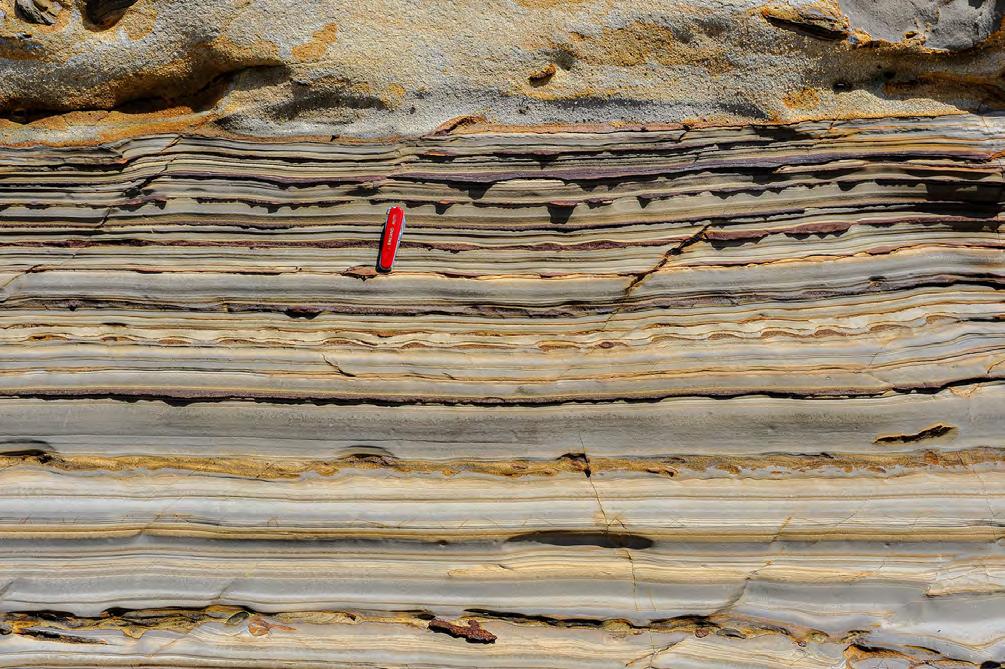
• Type 2 facies includes several types of beds thought to be genetically interrelated. These sandstone/mudstone couplets have individual thickness ranging between a few cm and 15-20 cm and their sandstone divisions display a variety of internal structures. These structures include soft-deformation features with “cloudy” units and preserved “fingers” (Figure 325), structureless muddy sandstone with pseudonodules of ripple-laminated sandstone, mudstone clasts and plant fragments (Figure 326), and structureless clean sandstone (Figure 327). Through a break in grain size, all these divisions are capped by one or few sets of current ripples that grade into overlying mudstone divisions Ripples may be locally deformed by water escape and/or downcurrent flowage of the entire sandy division. Type 2 facies can be interpreted as a typical deposit of “plume-triggered events” (Hizzett et al., 2017) which could not fully ignite to transform into
hyperpycnal flows (hyperpycnal turbidity current) and were thus forced to rapid deposition from a thin near-bed layer with high-sediment concentration. Figure 325 shows an example of these dense layers just sunk into a soft substratum and still preserving some of the original “fingers”. Further sinking produces complex “cloudy” features and transition to structureless liquefied layers. After a phase of limited bed erosion and mud clast incorporation, these flows move as cohesive laminar debris flows concomitantly with the deposition of current ripples from an overlying turbulent flow on their top (Figure 326). Through progressive loss of excess pore pressure and elutriation, the basal flow may transform into a basal layer of clean sand which keeps moving as a structureless layer impelled by an overlying, weak turbulent flow (Figure 327). At this point the flow has become a bipartite and poorly efficient “plume-triggered” turbidity current.
CHAPTER III TURBIDITE SYSTEMS: AN OUTCROP-BASED ANALYSIS 304
Fig. 324 - Type 1 facies showing good examples of parallel laminae starved ripples with varying length. Cretaceous Maceió Formation, Brazil. From Mutti (2019).
“finger”
Liquefied structureless layer
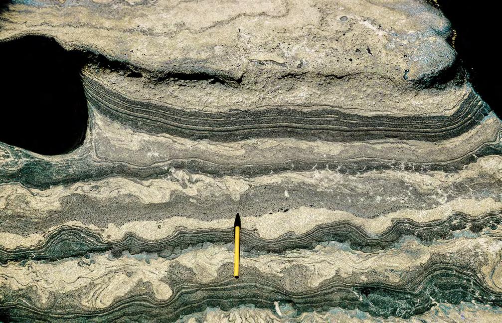
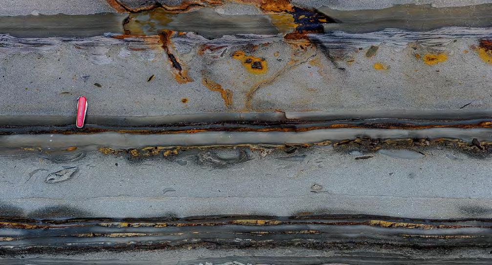
CHAPTER III TURBIDITE SYSTEMS: AN OUTCROP-BASED ANALYSIS 305
Fig. 325 - Facies 2. The photograph shows convection “fingers” preserved at the contact with a soft substratum and how “cloudy” structures evolve into a liquefied and structureless layer. Unrecorded Cretaceous stratigraphic unit, Cameroon. From Mutti, 2019.
Fig. 326 - Type 2 facies. Beds (yellow lines) showing a basal sandy division with pseudonodules, plant fragments and mudstone clasts sharply overlain by ripples. The sandy divisions are plume-triggered dense layers which underwent limited motion (flowage) during and immediately after deposition. Cretaceous Maceió Formation, Brazil. From Mutti, 2019.
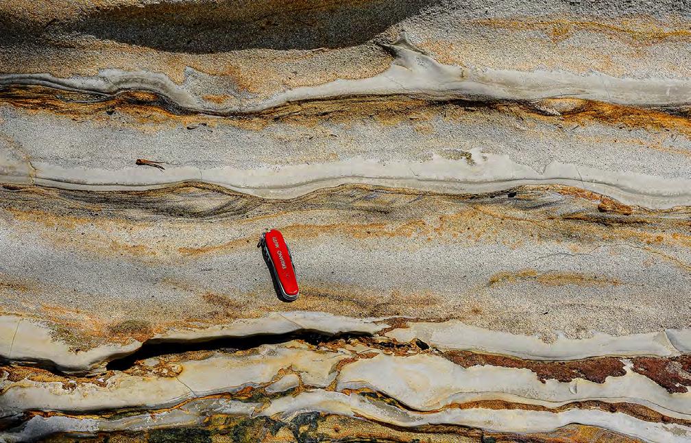
Type 3 facies consists of thin beds (cm-scale) with a lower subtly graded division of very fine and clean sandstone containing current-ripple laminae transitionally overlain by thinner, sinusoidal or parallel laminae (Figure 328). Typically, ripples show a final backstepping stage indicating waning flow conditions and transition to the overlying mudstone divisions.
More generally, as discussed in the conclusions, plumites also occur as an important component of turbidite systems forming a sort of background sedimentation separating more episodic and coarser-grained turbidite deposition.
VII.3 - THE IMPORTANCE OF FLOOD-GENERATED SIGMOIDAL CROSS-BEDDING: MAIN TYPES AND INFERRED PROCESSES
The more I look at the rocks, the more I become convinced that flood-generated sigmoidal cross-bedding is very common in both alluvial and shallow water strata, though developed on different physical scales
and with different characteristics. Both external geometry and internal sedimentary structures produced by this process are unique and easily distinguishable from other types of cross bedding. Admittedly, the term sigmoidal is quite generic, encompassing a great variety of features ranging from a convex-upward cross lamina to meters thick units formed by downcurrent migrating foresets. A review of the meaning of sigmoidal cross-bedding was provided by Roe (1987) pointing out the general consensus on the origin of the structure as indicative of a bedform transitional between dunes and an upper-regime plane bed. Nonetheless, particularly on the basis of new data, it seems necessary that the term be further specified when used.
Basically, flood-generated sigmoidal bedding forms where a flow starts to drop part of its load producing a basal carpet that keeps moving through traction along the bed, being sheared by an overpassing flow. Therefore, sediment moves through two distinct processes: the coarser-grained carpet moves intermittently along the bottom forming cross-laminae of migrating bedforms, whereas the finer-grained sediment moves fast-
CHAPTER III TURBIDITE SYSTEMS: AN OUTCROP-BASED ANALYSIS 306
Fig. 327 - Type 2 facies - Structureless fine-grained sandstone divisions sharply overlain by current ripples and sinusoidal laminae. Cretaceous Maceió Formation, Brazil.
er, being kept in suspension by the overlying flow. The sharp topset surface of the cross laminae is a bypass surface along which the basal carpet is continuously fed from behind. The setting is essentially similar to the microdelta of Jopling (1965) (Figure 329), albeit on a different scale and bears also some interesting similarities with the decoupled turbidity currents producing migrating megaripples (G4 facies, see Chapter II). When the overlying turbulent flow decelerates and starts to deposit, the bypass surface becomes depositional and sigmoidal laminae start to form indicating an aggrading topset (see later). Strictly speaking, the bedforms are not megaripples (dunes) because they lack their external geometry (see later). For this reason, they require a different term. I suggest “microdelta cross-bedding” or “flattened dunes”, or whatever you like. The same problem was clearly perceived by Roe (1987), who suggested the term “solitary to quasi-periodic bars” (see later).
As in tidal deposits, also in this case we can recognize individual sigmoidal units that, most commonly, occur in lateral sequences produced by their downcurrent
migration. In tidal sediments, an ideal sigmoid is oneevent bed (a simple bed) produced by the dominant tide of a diurnal or semi-diurnal cycle (see above); in flood-dominated sediments, an individual sigmoid is the product of an extremely short-lived pulse of the flood. The entire bed produced by a single flood (one-event bed) is thus more difficult to define, being composed of tractive sigmoidal units at the base and of sediment produced above and downcurrent by particle settling from the overlying suspension. Strictly speaking, an individual sigmoid is therefore an ideal laminaset in the sense of Campbell (1967) (see Chapter 1). Nonetheless, we will use also in this case the terms bed and bedsets to avoid communication problems. Small and short-lived floods produce bedsets which can be clearly defined over short distance. Larger and sustained (long-lived) floods produce bedsets whose exact recognition requires sufficiently large exposures. Types of deposit also depend on the textural composition of the incoming flow and its dominant process. Below, we will briefly review these deposits beginning from their most simple expressions.
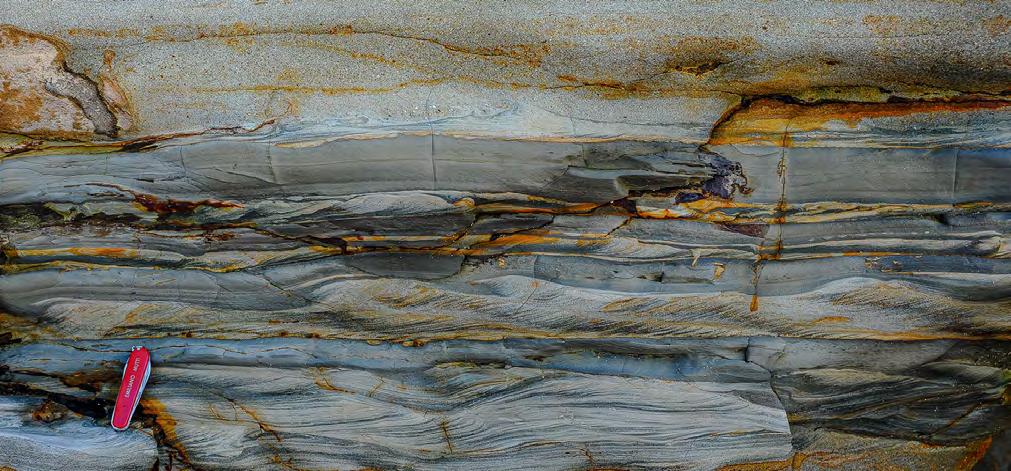
CHAPTER III TURBIDITE SYSTEMS: AN OUTCROP-BASED ANALYSIS 307
Fig. 328 - Type 3 facies consisting of thin and very thin beds of very fine-grained sandstone with ripple laminae overlain by a mudstone division. Note the backstepping pattern of ripples and the downcurrent transition from ripple cross laminae into thinner sinusoidal laminae. These beds are a typical deposit of dilute turbulent flows through a traction-plus-fallout process. Cretaceous Maceió Formation, Brazil. From Mutti, 2019.
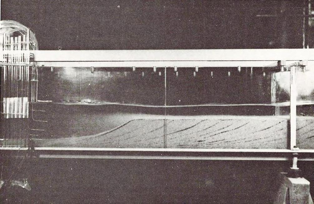
Figure 330 shows an example of a small flood-generated sigmoidal unit (A) produced by a weak and shortlived flood. The unit is identified by a basal sandy and cross-stratified division (microdelta) that abruptly wedges out upcurrent resting on a local scour. The unit thickens downcurrent, downlapping onto a progressively depositional surface until it gradually thins and passes, further downcurrent, into a train of ripples forming the bottomset of the feature. The upper boundary of the basal cross-stratified unit is a flat and essentially horizontal erosional surface that is capped by a train of ripples forming the drape the entire feature. The interpretation of this simple sigmoidal unit is that after the erosion of the upcurrent scour by turbulence a microdelta is formed, with foreset laminae moving downcurrent sheared by an overlying flow along an erosional topset. Late-stage flood deposits are recorded by ripple trains resting on the erosional surface. A similarly thin flood unit (B) occurs just above.
Figure 331 shows an example of sigmoidal bedding generated by short-lived and powerful floods (flash
floods) of considerably higher strength than that of Figure 330 here involving conglomerates and pebbly sandstones. Two sigmoidal units (A and B), closely following each other in a microdelta-type setting and possibly being part of the same flood event, are separated by a drape of current-laminated sandstone truncated at the topset surface. This sandstone is slightly deformed in a small compressional feature probably produced by the impact of the overlying flow. Unit A consists of clast-supported and relatively well-sorted conglomerates that fill a large scour with high-angle and fining-upward cross laminae dipping in a downcurrent direction. Angle of dip of the cross-laminae and size of the clasts gradually decrease upward and downcurrent, passing into a series of graded pebbly sandstones with locally scoured bases. Unit B has a similar internal configuration. Both units are draped by a sandstone bed in turn overlain by mudstones and paleosols. The interpretation offered for these units, largely based on a well-exposed facies association, implies the sudden downcurrent transformation and dilution (hydraulic
CHAPTER III TURBIDITE SYSTEMS: AN OUTCROP-BASED ANALYSIS 308
Fig. 329 - The microdelta of Jopling (1965). Explanation in the original legend. Note the toplap geometry of depositional units. Sediment is added to foresets by the dense layer at the base of the flow.
jump) of an extremely poorly sorted, matrix-supported and highly erosive debris flow. The matrix-free coarsegrained sediment resulting from the transformation was sheared, sorted and bypassed by the residual pulsating flow forming a limited number of downcurrent accreting sigmoids consisting of pebbles and coarse sand. A sharp and virtually flat erosional topset surface indicates substantial sediment bypass. Each of these units is a “flood-generated sigmoidal bar” in the sense of Mutti et al. (1996, 2000; see above).
Figure 332 shows a good example of sigmoidal bedding produced by a flood of considerable strength. The unit consists of several coarse-grained sigmoids forming a basal microdelta with a thickness of about one meter and an observable length of approximately 10 meters. The base of the unit is sharp and characterized by numerous shallow scours. The top of the unit
is more complex being expressed by erosional surfaces indicating sediment bypass or by the transition of sinusoidal cross strata into thin horizontal topset deposits. The micro-delta division shows downcurrent variations in terms of grain size, thickness of individual sigmoids, types of cross laminae, and both basal and upper contacts indicating pulsating flow conditions within an overall waning process. The suggested interpretation is that the microdelta was accreting downcurrent through flood pulses, being sheared by a bypassing flow. The sedimentary structures observed in the bottomset deposits indicate that the flow was essentially supercritical with the development of antidune bedforms. The most distal deposits associated with this kind of facies are thin-bedded and finegrained sandstones characterized by climbing ripples, indicating suspension sedimentation from trailing, dilute turbulent flows.
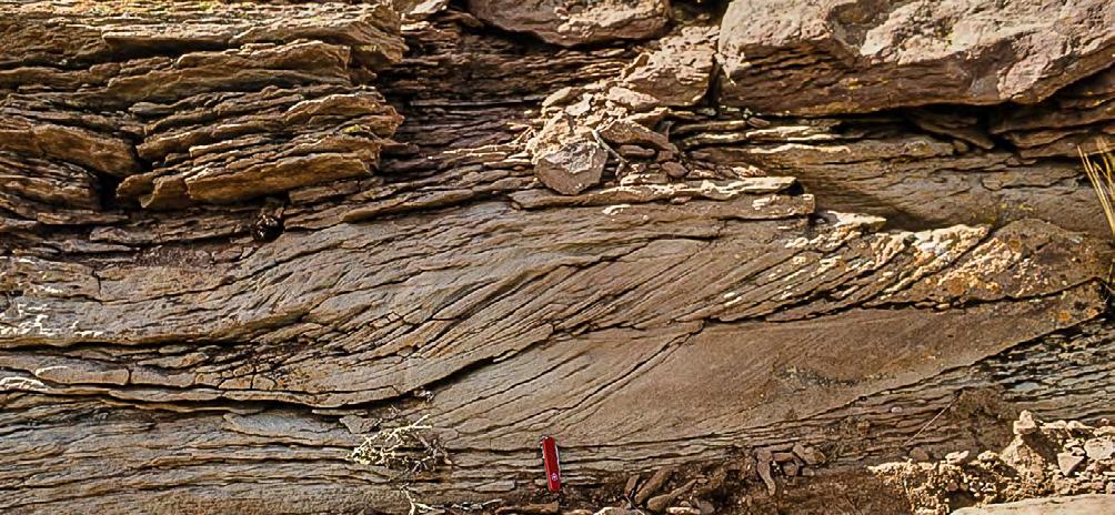
CHAPTER III TURBIDITE SYSTEMS: AN OUTCROP-BASED ANALYSIS 309
A B
Fig. 330 - Small flood-generated sigmoidal units (A and B) in ephemeral lake deposits. Cretaceous Rayoso Group. Neuquén basin.
Bypass surface
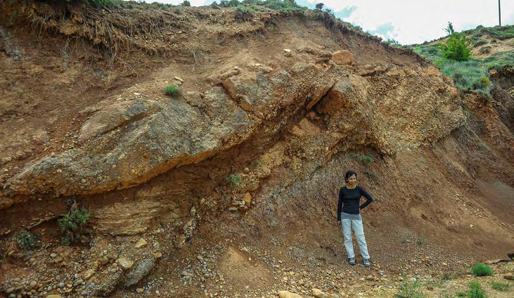
Along bed sliding and local deformation
Current-laminatedsandstone
Paleosol clast
Deep scour
Paleosol
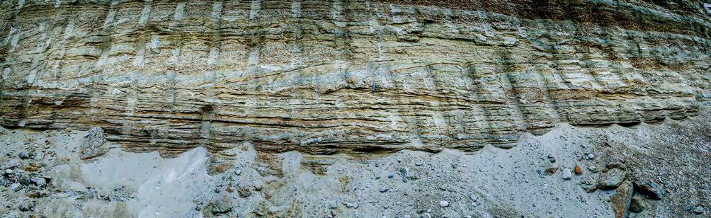
CHAPTER III TURBIDITE SYSTEMS: AN OUTCROP-BASED ANALYSIS 310
Fig. 331 - Flood-generated sigmoidal units arranged in a microdelta-type setting. See text for explanation. Paleocene-Eocene TrempAger Group, south-central Pyrenees.
B
Fig. 332 - Sigmoidal bedset produced by a pulsating flood, Quaternary, Rio La Leona, Santa Cruz province, Argentina. Encircled pencil for scale. (Courtesy of Carlos Gulisano). See text for a more detailed explanation.
A
The most common occurrence of sigmoidal bedding is probably that described by Mutti et al. (2000) and Tinterri (2007, 2011) and observed in river-mouth deposits, i.e., the region where hyperpycnal plumes plunge to become underflow (see above). In this critical zone, beds can be either horizontal or dipping in a seaward direction, comprising the typical clinoforms of mouth-bar progradation. These beds are generally composed of relatively well-sorted and medium- to coarse-grained sandstone containing lateral sequences of sigmoids. These sigmoidal units are essentially microdelta features sheared by an overlying and bypassing turbulent flow and recording the waxing and waning pulses of the pulsating original flood. Individual sigmoids have the tendency to thin and flatten in a downcurrent direction and the microdelta feature is characteristically bounded by an upper truncation surface.
In many other cases, sigmoidal cross-bedding is expressed by more subtle features which may be more difficult to identify and interpret, though being clearly related to the microdelta scheme. Figure 333 portrays an example showing vertically stacked and amalgamated units separated by erosional surfaces that can be either flat and horizontal, slightly oblique, or gen-
tly convex upward. This type of bedding can be easily mistaken for classic tabular cross-bedding produced by the migration of 2D megaripples (see above). However, careful inspection of the photograph allows for a further step in our understanding of sigmoidal bedding. The units in the lower half of the exposure are thinner, bounded by a broadly convex-upward erosional surface and clearly show the internal structure produced by the lateral sequence of individual sigmoidal units over very short distance. In the upper half of the exposure, beds are thicker, bounded by flat surfaces, and with a less obvious arrangement into internal lateral sequences. The terms “flattened dunes” or “flat-topped cross-bedding” would be tempting in this case. An easy conclusion is that the type of sigmoidal bedding records the steadiness of the flood flow. Highly unsteady flows would result in closely spaced sigmoidal beds showing thickness variations over short distance. Steady or quasi-steady flows would conversely tend to form sets of similar cross laminae with greater lateral extent and for which the sigmoidal geometry can only be detected in large exposures. This kind of bedding is basically the same as that described by Roe (1987) in Late Precambrian fluvial sandstones, northern Norway.

CHAPTER III TURBIDITE SYSTEMS: AN OUTCROP-BASED ANALYSIS 311
Fig. 333 - Vertically stacked and amalgamated cross-bedded sandstone units separated by horizonal, slightly oblique, or broadly convex-upward surfaces. See text for explanation. Bundsandstein, Killsberg Park, Stuttgart.
For the reader’s convenience, the scheme of Figure 334 summarizes the main features of sigmoidal bedding and attempts some interpretations. Sigmoidal units are subdivided into 1) bypass features (A1 and A2) and 2) bypass plus depositional features (B1 and B2). The former includes sigmoidal bedsets (Figure 335) and flat-topped sets of cross laminae (Figure 333), both being bounded by an erosional upper surface indicat-
ing prolonged bypass. The latter include both forestepping (Figure 336) and backstepping (Figure 337) features produced by highly pulsating flows. The falling stage of each pulse gives way to flow deceleration followed by deposition of slightly finer grained sediment that drapes the cross bedded unit with sinusoidal laminae. Under these conditions both topsets and bottomsets can aggrade.
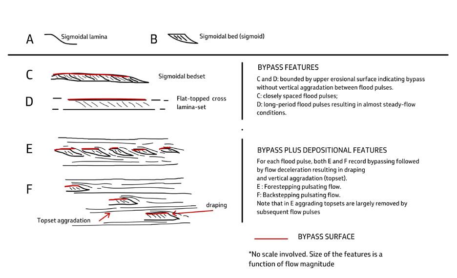
CHAPTER III TURBIDITE SYSTEMS: AN OUTCROP-BASED ANALYSIS 312
Fig. 334 - Some characteristic features of sigmoidal bedding. Note the basic difference between sigmoidal beds and bedsets indicating bypass without aggradation (A1 and A2) and cosets produced by pulsating flows where bypass (cross strata) and vertical aggradation (topsets and bottomsets) alternate (B1 and 2).
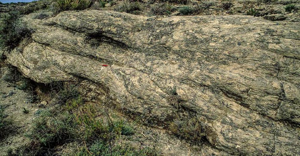
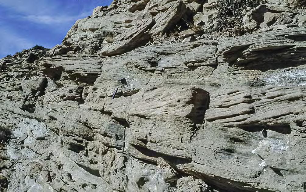
CHAPTER III TURBIDITE SYSTEMS: AN OUTCROP-BASED ANALYSIS 313
Fig. 335 - Typical example of A1 deposit expressed by closely spaced sigmoids bounded by an upper, broadly convex-upward erosional surface indicating bypass (red line). Eocene Figols Group, south-central Pyrenees.
Fig. 336 - Typical example of B1 deposit. Within the same flood, cross-bedded sigmoidal units (yellow) record individual pulses. The falling stage of each pulse is recorded by finer-grained partings allowing for topset and bottomset aggradation. The entire flood unit is forestepping. Cretaceous Agrio Formation, Neuquén basin.
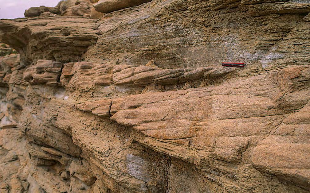
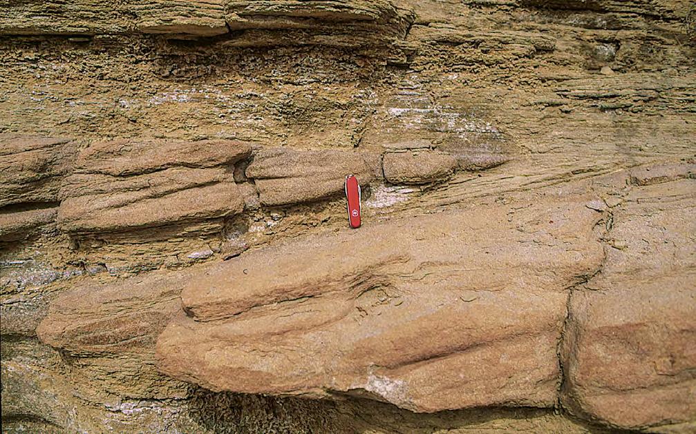
CHAPTER III
SYSTEMS:
314
TURBIDITE
AN OUTCROP-BASED ANALYSIS
Fig. 337 - Close-ups of Figure 64 showing falling-stage finer-grained partings separating and draping cross-bedded sigmoids and extending into bottomset and topset.
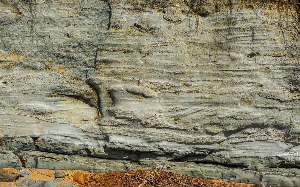
VII.4 - FLOW REGIME VARIATIONS AND “HUMPBACK DUNES”
Down to the scale of individual beds and their internal structures produced by a single flood and related flow variations in space and time, the examples shown in Figures 339 and 340 illustrate an important problem arising from the downcurrent transition of foreset cross-stratification into its associated bottomset deposits. As clearly shown by the two beds of Figure 339, large-scale tangential cross laminae pass downcurrent into gently convex-upward cross laminae which, in turn, pass into wavy or horizontal laminae in the bottomset and topset draping the underlying microdelta. Figure 340 and the line drawing of Figure 341 attempt to explain this kind of setting by assuming that the bypassing flow undergoes deceleration resulting in the rather abrupt cessation of foreset progradation expressed by the sudden appearance of sinusoidal laminae. These laminae are followed in a downcurrent direction by progressively flatter laminae that markedly expand in the same direction and thin and converge toward the topset region. These laminae are termed herein “healing laminae”. Upon re-establisment of a smooth and flat
bed, supercritical, thick horizontal laminae aggrade on the topset. The lack of climbing ripples and mudstone divisions at the top of these flood units suggests that fines transported by trailing turbulent flows bypassed this region or were removed and re-suspended by subsequent flood flows.
The relations between foresets and their associated topset and bottomset deposits has been amply discussed by Fielding (2006) with emphasis on “humpback dunes”, which are characterized by cross laminae with a sigmoidal profile involving topset, foreset and bottomset and commonly diverging in a downcurrent direction before flattening out in the bottomset. Following the results of flume experiments by Saunderson and Lockett (1983), Fielding (2006) interprets these features as recording the transition from dune to upper plane stability conditions, i.e., from subcritical to supercritical flow conditions, or viceversa. Rising flow power would be expressed by topsets with supercritical parallel (plane bed) laminae, whereas falling flow power would conversely result into the lack of topset deposits replaced by an erosional surface or smallscale bedforms on the stoss side of the dune.
CHAPTER III TURBIDITE SYSTEMS: AN OUTCROP-BASED ANALYSIS 315
Fig. 338 - Example of B2 deposit. Cross-bedded sigmoidal units decrease in thickness from base to top indicating backstepping of a pulsating flood. Red lines indicate the base of each sigmoidal unit. White lines indicate topset deposits: Cretaceous Maceio Formation, Japaratinga.
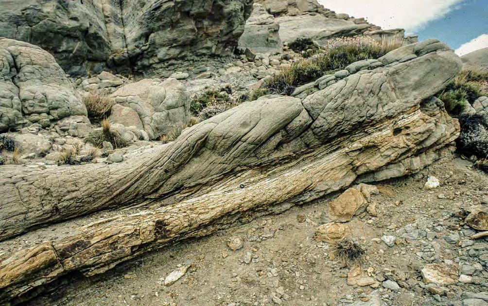
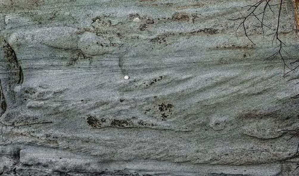
Bypass surface
CHAPTER III TURBIDITE SYSTEMS: AN OUTCROP-BASED ANALYSIS 316
Fig. 339 - Flood-generated sigmoidal units arranged in a microdelta-type setting. See text for explanation. Paleocene-Eocene Tremp-Ager Group, south-central Pyrenees. (A) Angular cross laminae; (T) Tangential cross laminae; (W) wavy or horizontal laminae e (H) “Healing” laminae.
Fig. 340 - Flood units (red lines indicate boundaries). The lower one shows the transition from a prograding set of cross laminae into aggrading topset deposits formed during the falling stage of the flood. Thick red line indicates the bypass surface. See line drawing of Figure 69 for an explanation. Cretaceous Maceió Formation, Brazil.
W H T A
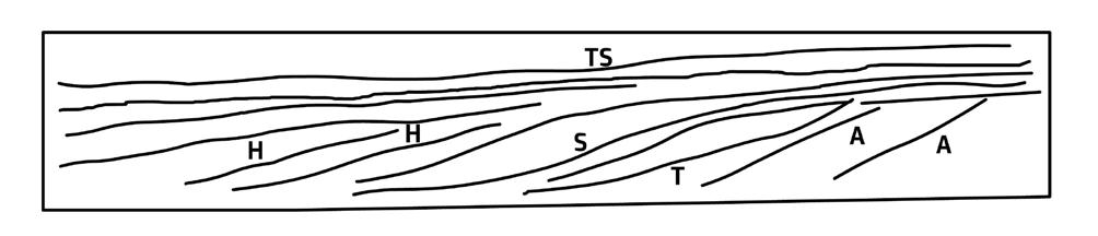
The interpretation that I offer for this problem is considerably different and probably simpler. As long as the microdelta or flattened dune is bounded above by an essentially flat erosional surface and the overlying flow is bypassing, there is no topset aggradation, and probably little sedimentation in the adjacent bottomset. During this time, sedimentation of suspended load is taking place farther downcurrent. Ideally, the flood peak (maximum flow discharge) should be recorded by the thickest sigmoid of the microdelta. When the flow decelerates suspended sediment starts to fallout and aggrade, draping first the high-angle cross laminae of the microdelta with sinusoidal laminae extending from the topset to the toeset. Increased sedimentation rates because of further flow deceleration result into a well-developed topset and bottomset that appear as essentially horizontally stratified. Therefore, the “humpback” geometry is not related to the transition from lower to upper flow regime, but rather to flow deceleration and ensuing deposition. Conversely, if the flow is accelerating the microdelta would undergo partial or total erosion and sediment resuspension.
The above interpretation may also explain why microdeltas are commonly bounded by an upper flat and erosional surface. This surface is probably a supercritical bedform (plane bed or low amplitude antidunes) along which bypassing takes place. No typical dune geometry might develop under these conditions.
VIII - MAIN TYPES OF FLOOD-DOMINATED SYSTEMS, ELEMENTS, AND FACIES
VIII.1
- INTRODUCTION
Mainly based on observed facies, documented by a great number of photographs, and limited and cau-
tious emphasis on processes, an attempt is made below to offer some criteria to enter this largely unexplored and fascinating domain. Part of the following sections are mostly based on unpublished results of outcrop studies I carried out over the years with the help of my students in the Pyrenees, Spain, the Tertiary Piedmont Basin and the Oligocene and Miocene of Calabria, Italy, i.e., basin fills from highly tectonically mobile settings. Many additional observations were made in other basins, especially in the Neuquen basin, Argentina. It would be impossible to review in this book the geology and the stratigraphy of all these basin fills. As far as the Pyrenees are concerned, a useful and very simple summary can be found in Mutti (2019).
The basic scale of observation is that of outcrops, though integrated whenever possible within their local and regional stratigraphic context. The main purpose is that of describing an outcrop in terms of facies and then interpreting these facies and their association in terms of (inferred) processes and ultimately environment of deposition. This approach is well summarized by Walker (1992) who considers facies analysis as a subdivision of rocks in “bite-sized pieces” (facies) that can be re-assembled into genetically related associations. The interpretation is intended to make sense of the outcrop within the evolution of the system under consideration and more generally to add a piece to the puzzle of the basin fill history. The same approach holds true for core analysis.
In isolation, one outcrop can be very interesting from a sedimentological standpoint, but it may also be highly risky if we do not know what there is above, below and laterally to what we are observing. From the preceding pages, the reader has certainly become aware that climbing ripples or graded beds, for example, are com-
CHAPTER III TURBIDITE SYSTEMS: AN OUTCROP-BASED ANALYSIS 317
Fig. 341 - Humpback-like bedforms and flow velocity variations within flood units. Schematic line drawing of bed of Figure 69 showing the gradual transition of angular cross laminae (A) in tangential cross laminae(T) and eventually in sigmoidal cross laminae (S). “Healing” laminae (H) expand downcurrent and thin and converge toward the topset. Horizontal laminae, or topset laminae (TS), are unaffected by previous depositional relief. The basal cross-bedded unit is bounded by an upper bypass surface (red line) that truncates the underlying angular cross laminae. The surface gradually becomes depositional farther downcurrent. The setting is interpreted as the product of decreasing flow velocity followed by sediment fallout from an overlying suspension.
mon in many types of deposit ranging from alluvial to deep-water turbidites. Therefore, their recognition in an outcrop does not mean much in terms of environment. Attempting an environmental interpretation is very difficult because, in most cases, environments are poorly defined even in the Recent. Generally, we have a good idea of what a specific environment looks like if we are dealing with those environments, we can directly observe in the Recent, where we can integrate physiography, processes and deposits. Recent tidal flats or certain types of beaches are extremely well known in this respect, as are some fluvial point bars or other types of alluvial and nearshore environments. Within these environments, we can go even further and recognize sub-environments, each being characterized by its morphologic expression, processes and types of deposit. For example, in a tidal flat we can recognize sand flats, mixed flats and mud flats or, in a beach, a shoreface, a foreshore, and a backshore (see Chapter I).
Unfortunately, when moving into progressively deeper waters this kind of knowledge decreases considerably for the simple reason that these environments are beyond our direct observation. Turbidite and contourite systems are good examples of the above limitation. Recent advances in marine geology techniques and in 3D seismic permit to define locally detailed geomorphologic seascapes (see “seismic geomorphology” of Posamentier and Kolla, 2003) of these systems, but sparse coring prevents significant integration of these data with types of deposit and processes. To summarize, with the exception of limited instances, interpreting specific environments and sub-environments from outcrop analysis is a hard task and this explains why an approach based on the recognition of depositional systems and their component elements, based on their facies and facies associations (see preceding chapters), appears at present as the most practical one. An even more simplified approach can be that based on the proximality concept, i.e., a measure of the distance from an ideal starting point of deposition. The approach, originally introduced for turbidite sediments (see Chapter II), is also applicable to many other types of deposit and attempts to define the position of a facies or facies association relative to an overall process implying overall waning flow conditions with distance and time. Therefore, for example, an alluvial fan system can be subdivided into proximal, intermediate, and distal elements with reference to its facies and facies associations without taking into account other specific characteristics of the environment such as, for instance, size, longitudinal profile and channel network.
Even more difficult becomes a detailed environmental analysis when dealing with flood-dominated systems, a
kind of sedimentation with which we are not familiar and underrepresented in the Recent. Fortunately for us, we are living in a geological time where great floods are not frequent and, when they occur, processes and environment are inherently hostile to direct observation.
Despite the above limitations, we will review in the following sections some basic types of flood-generated systems and elements and their component facies and facies associations that can be easily and objectively recognized in the field. It will be noted that, with the exception of some river deposits (see later), all these sediments lack bed load structures produced by tractive currents in the lower flow regime, i.e., by the normal process through which sand and gravel are transported in most modern fluvial settings. More specifically, these sediments are conspicuous for the virtual lack of trough cross-bedding as defined in previous sections, i.e., the product of migrating 3D megaripples through tractional processes in the lower flow regime. Conversely, most of these sediments can be easily interpreted as the result of waning sediment gravity flows through the deposition of overall graded units. The waning stage follows an initial waxing stage rarely preserved (see above). Some of these deposits are dealt with in detail, others, volumetrically less important or less studied and understood, are treated in a more cursory way.
VIII.2 - TERMINOLOGY PROBLEMS
From the preceding pages, the reader has certainly become aware that a very complex and confusing terminology exists as to the different types of flows that may originate as a consequence of floods. Personally, I believe that terminology is one of the major problems hampering scientific communication. Regrettably, I am also aware that I contributed myself to this problem in several papers dealing with both turbidites and flood-dominated fluvio-deltaic systems. On the other hand, flows and their processes are so inherently complex, and their study has been carried out by so many workers through so many different approaches that some confusion is unavoidable.
It should also be clear that the deeper we go into flood-generated flows and their deposits, the more evident become the similarities with turbidity currents and turbidites. Therefore, as reiterated in the preceding pages, it is useful to keep in mind also this second type of sedimentation and its terminology. The reader is thus referred to Chapter II where he can find further and detailed information on the complexity of these flows and their deposits. The basic and simple distinction between dense flows and dilute turbulent flows is maintained also in the following sections.
CHAPTER III TURBIDITE SYSTEMS: AN OUTCROP-BASED ANALYSIS 318
VIII.3 - THE BASIC TYPES OF FLOOD-DOMINATED ALLUVIAL AND FLUVIO-DELTAIC SYSTEMS
Flood-dominated alluvial and deltaic sediments that are reviewed below include:
• Alluvial fans and their terminal flood basins,
• River deposits (only a preliminary and highly incomplete account),
• Delta-front and prodeltaic elements.
These sediments have in common a basic motif: in a down-flow direction, as well as through the short time of an individual flood, coarse-grained deposits, laid down by freezing of dense sediment gravity flows or by tractive processes taking place below bypassing powerful flows, invariably grade into finer-grained and current-laminated facies recording deposition from suspended load. The process takes place via a variety of transitional facies types and by-pass surfaces in both space and time, i.e., along the original depositional profile and within individual beds. Comparison of facies tracts that can be reconstructed from these sediments and those observed in turbidite systems (see Chapter II) leaves little doubt that the processes are very similar.
VIII.3.1 – Alluvial fans and their terminal flood-basins
These depositional systems typically develop in orogenic belt basins after and/or during major phases of structural deformation with ensuing uplift and subaerial erosion of substantial portions of the orogenic wedge, as well as in fault-bounded basins associated with extensional or strike-slip settings. The most classic occurrence of this type of sedimentation is probably that of the so-called “basal conglomerates” unconformably resting upon highly structurally deformed portions of an orogenic wedge and recording the beginning of a new sedimentary cycle. In many of the studied examples, alluvial fan deposition is associated with that of fan-deltas, in marine or lacustrine settings. Marine fan-deltas typically develop during relative sea-level rise above a basal succession of alluvial-fan deposits.
Alluvial fans are dealt with in an abundant literature showing the great variability of these depositional systems and the many controversial opinions about
their definition and characteristics (e.g., Blair and McPherson, 1994a, 1994b; Harvey et al., 2005; Ventra and Clarke, 2018). Here, we limit ourselves to consider alluvial fans in the sense of Blair and McPherson (1994a), i.e., depositional features formed in high-gradient piedmont settings where feeder channels of upland drainage basins intersect the mountain front. Even in modern settings and under normal conditions, these alluvial fans are characteristically dominated by episodic sedimentation (debris flows and sheet floods) producing high-sloping, semiconical features with plano-convex cross-sectional geometry (Figure 342). Size and geometry of individual fans largely depends on the size of the drainage basin, the topographic gradient, and the mobility of the flows. Blair and McPherson (1994a) recognized two intergradational end members, dominated by cohesive debris flows and sheet flood respectively (Figure 343).
These modern alluvial fans may extend and die out into terminal flood basins, contribute water and sediment to axial river systems (trunk rivers), or enter an adjacent standing body of fresh or seawater, forming the subaqueous element of both lacustrine and marine fan-deltas, i.e., a delta-front element (see later). Large, low-gradient fluvial-dominated alluvial fans and “wet” fans are omitted in the following pages.
The Eocene and Oligocene successions of the southcentral Pyrenees provide spectacular examples of alluvial fan deposition. The exposures of the late Eocene-Oligocene Pobla de Segur Conglomerates, near Tremp, show a series of relatively small alluvial fans fed from two different sources (Figure 344). The geometry of individual fans is almost perfectly preserved as well as their facies changes into adjacent flood basins and ephemeral lakes. As shown in Figure 345, the setting is so clear that a direct visual comparison can be made with the classic alluvial fans of the Death Valley, California. Excellent exposures are also provided by the Oligocene alluvial fans developed along the northern margin of the lacustrine Ebro basin and its time-equivalent intra-montane basins. Because of their very complex and still poorly defined stratigraphy, all the above sediments are simply referred to hereafter as Pobla de Segur and Cajegar conglomerates with reference to intramontane settings, and to Ebro basin with reference to the northern margin of the large lacustrine foreland basin developed along the southern portion of the Pyrenean orogeny.
CHAPTER III TURBIDITE SYSTEMS: AN OUTCROP-BASED ANALYSIS 319
Flood-dominated alluvial fans are restricted herein to depositional systems where flood-generated sediment gravity flows and their downfan transformations dominate sedimentation from proximal to distal regions, i.e., from fan apexes to terminal flood basins. Fluvial deposits, recording periods of time during which permanent or semi-permanent fluvial channels were able to move sediment downfan through tractive bedforms are virtually absent. Clearly, flood-dominated systems of this type are a major departure from some widely accepted models where debris flows and sheet floods are gradually replaced downfan by typical and permanent braided streams (see the classic example of the Van Horn Sandstone, Texas, described by McGowen and Groat, 1971; see also comments by Blair and McPherson, 1994a). Small and surficial braided-distributary channels are only found as feeders of very small delta systems in ephemeral lacustrine basins during periods of essentially fan quiescence. Also, these channelized features are basically flood dominated. Most of the proximal elements of alluvial fan systems are recorded by sediments probably laid down beyond the intersection
point, that is where flows exit deep feeder channels, undergoing expansion and initial deposition.
VIII.3.1.1 – The importance of terminal flood basins
The models of Blair and McPherson (1994a) depict alluvial fan deposition essentially under “normal” conditions. When ancient flood-dominated alluvial fans are considered, these models appear inadequate to describe the main depositional zone, which is located farther downfan of the more proximal, high-sloping semiconical feature (the fan itself) and is essentially flat lying. This zone, herein termed terminal flood basin, forms a sandy depositional zone at variable distance from the intersection point and is clearly the final depositional element of genuinely flood-dominated alluvial fans. The distance of terminal flood basins from their feeder fan channels is highly variable, being strictly a function of the fan and its drainage basin size, volume, sediment concentration and textural composition of flood-related flows, and basin configuration. The suggested depositional model is shown in Figure 346.
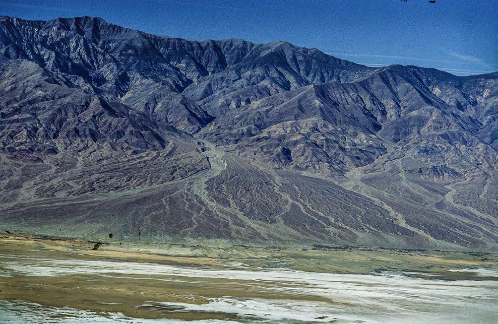
CHAPTER III TURBIDITE SYSTEMS: AN OUTCROP-BASED ANALYSIS 320
Fig. 342 - A classic alluvial fan from the Death Valley with its surficial braided distributary channels indicating a period of fan quiescence.
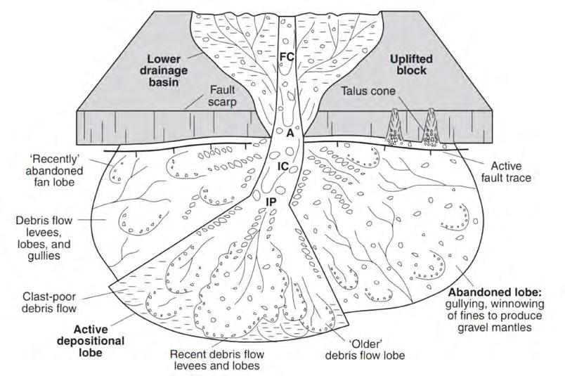
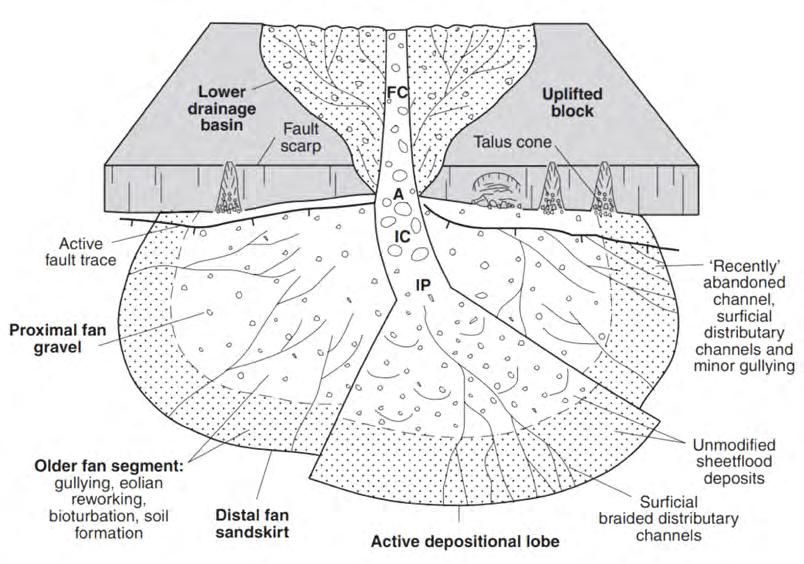
CHAPTER III TURBIDITE SYSTEMS: AN OUTCROP-BASED ANALYSIS 321
A B
Fig. 343 - Plan-view models of debris-flow (A) and sheetflood (B) dominated alluvial fans according to Blaire and McPherson (1994a). A – Fan apex; FC – Feeder channel; IC – Incised channel; IP – Intersection point.
Cretaceous carbonates of the drainage basin
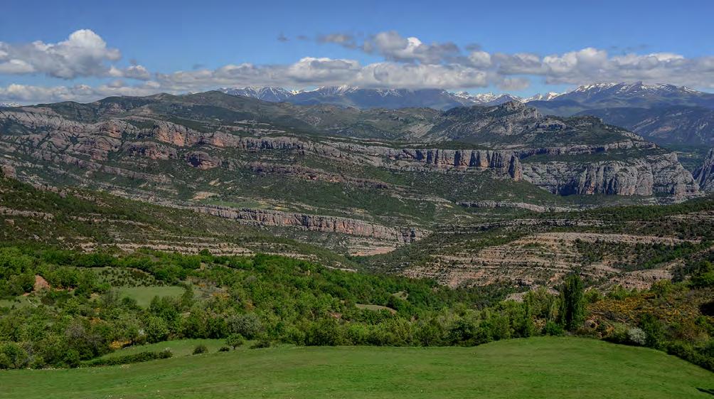
Mostly debris flow deposits
Tabular sheet-flood deposits
are roughly from the north i.e., flowing toward the viewer. Note the lenticular geometry of Individual fans. Most of these fans are almost entirely made up of debris flow deposits. Note the exposed rocks (carbonates) of the drainage basin of the “grey” fans. Tabular sheetflood deposits in the lower part of the photograph belong to an older and much larger fan fed from a southern source.
Death Valley
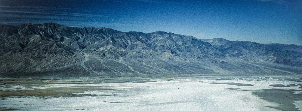
Late Eocene-Oligocene Pobla de Segur conglomerates, south-central Pyrenees
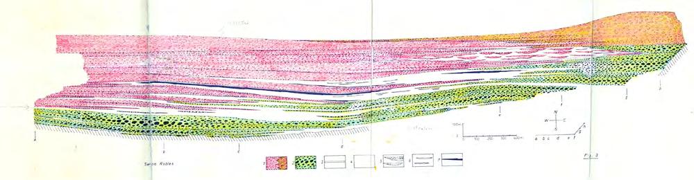
Note that this fan is fed from the opposite side
345 - Comparing modern and ancient alluvial fans.
CHAPTER III TURBIDITE SYSTEMS: AN OUTCROP-BASED ANALYSIS 322
Fig. 344 - The spectacular exposure of the late Eocene-Oligocene conglomerates of Pobla de Segur, near Tremp, in the south-central Pyrenees (see cross-section in Figure 322, see also Chapter I; see Figure 4). Paleocurrents
Fig.
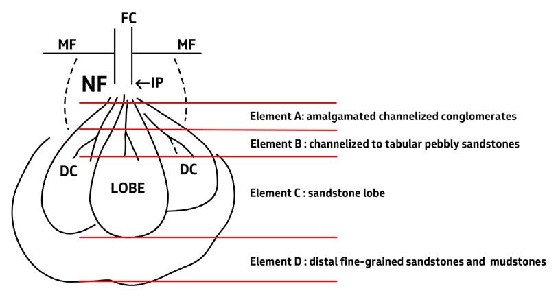
Terminal flood basins are essentially similar, say almost identical to the “lobe region” of turbidite system, recording deposition of sand-laden flows in tabular or broadly lenticular bodies herein referred to as “terminal sandstone lobes” (see later). The size of these lobes must be largely a function of the size of the feeder system. In outcrop, these features range from small elements, with length in the order of tens of meters, to medium-size elements with length up to a km-scale.
Terminal flood basins may develop in flood ponds, ephemeral lakes, or semi-permanent lakes, thus forming a broad spectrum of environments including lacustrine fan-deltas. Marine fan-deltas are dealt with in detail in a later section.
VIII.3.1.2 – Flood-dominated alluvial fans
Flood-dominated alluvial fans of orogenic belt basins can be simply seen as depositional systems consisting of four main intergradational elements that develop downfan following flow-transformation processes (Figure 346):
• A proximal element, or element A, dominated by matrix-supported and poorly sorted conglomer-
ates, in thick to very thick beds commonly amalgamated or separated by thin and laterally discontinuous sandstone and muddy partings. Individual beds commonly display lenticular geometry, multiple grading and scoured bases. These beds generally stack to form roughly parallel-sided lithofacies up to several meters thick separated by minor amounts of discontinuous finer-grained facies (Figures 347 to 351 A). These deposits are the product of dense gravelly flows with variable amounts of mud and therefore of internal strength (see Chapter II). Most commonly, a matrix composed of sand and small pebbles indicates deposition from frictional flows. The erosive character of most of these flows is documented by the abundance of scours and basal sole markings (Figure 351 B).
• An intermediate element, or element B , consisting of graded, pebbly to cobbly sandstones and occurring as m-thick broadly lenticular and channelized features or similarly thick roughly tabular units (Figures 352 to 354). This element typically consists of bipartite beds, most commonly amalgamated, where a basal division of pebbly to cobbly conglomerate with a sandy matrix is either sharply or transitionally overlain by
CHAPTER III TURBIDITE SYSTEMS: AN OUTCROP-BASED ANALYSIS 323
Fig. 346 - Suggested depositional model. FC – Main feeder channel; MF – Mountain front; IP – intersection point (where the feeder channel merges with the surface of the fan); NF – Alluvial fan shape under conditions of normal flood regime; DC – Distributary channels. Note how high-magnitude floods displace main loci of deposition far away from the feeder channel into low-gradient terminal regions. Most of these basins are ephemeral, flood-generated lakes (floods transport also water !!). See text for more details.
crudely laminated or structureless sandstone. In some cases, conglomerate divisions are directly superimposed and amalgamated without intervening sandstone units. Conglomerate divisions are in most cases lenticular as a result of scouring or of an original plano-convex upward geometry (see antidune configuration of Blair and McPherson, 1994). The most likely origin of these beds is that of sheet floods. These flows are herein termed sheet flows and thought to be
related to the downcurrent transformation of debris flows. A sheet flow is a bipartite flow where a basal, dense and frictional flow moves downfan impelled by inertia forces and/or by the shearing imparted from an overlying more dilute flow. Some conglomerate divisions comprise the entire thickness of the bed, being bounded by an upper bypass surface (Figure 355); in other cases, the conglomerate division forms a few pebbles thick unit below a sandstone division (Figure 356).
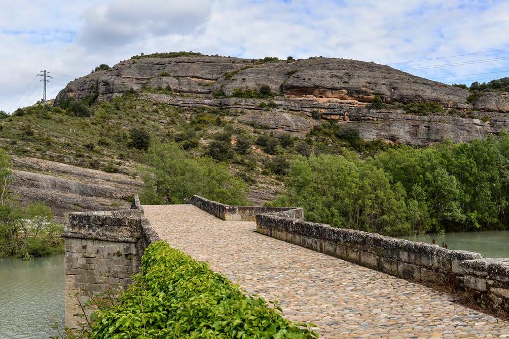
CHAPTER III TURBIDITE SYSTEMS: AN OUTCROP-BASED ANALYSIS 324
Fig. 347 - Alluvial fans – Element A: fine-grained intercalations define m-thick, roughly tabular units consisting of thick, amalgamated beds of poorly-sorted conglomerate deposited by dense gravelly flows (paleoflow to right). Oligocene Ebro basin, south-central Pyrenees.
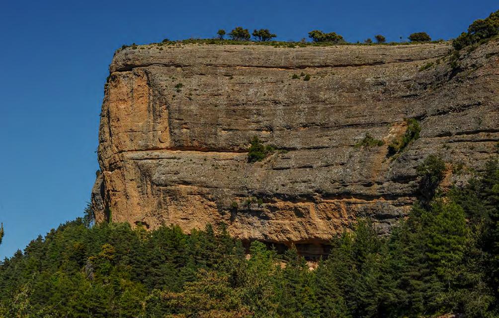
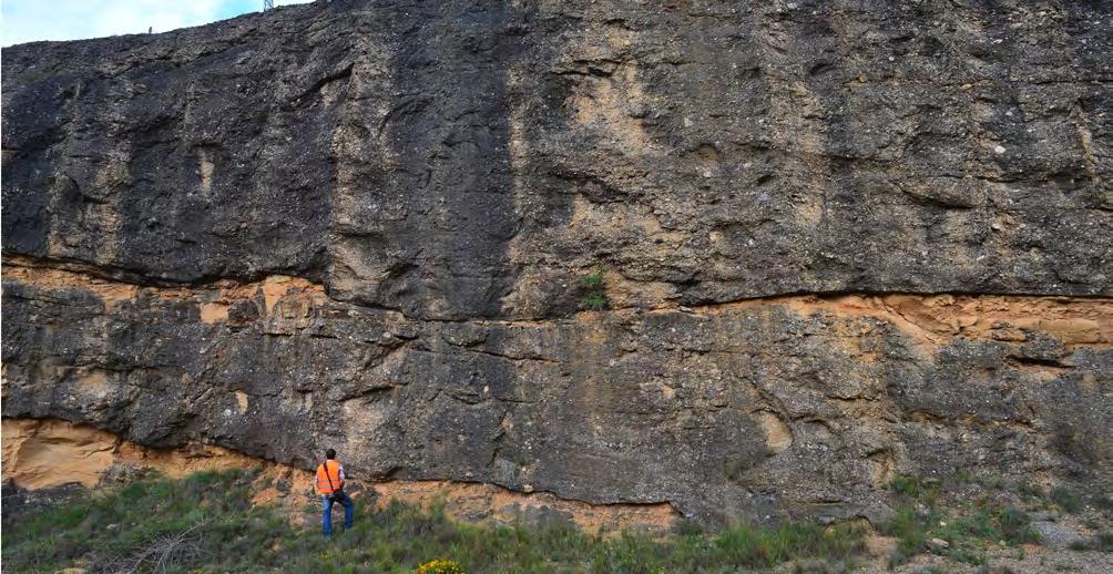
CHAPTER III TURBIDITE SYSTEMS: AN OUTCROP-BASED ANALYSIS 325
Fig. 348 - Alluvial fans: Element A – Tabular conglomerate units separated by highly discontinuous, thin and finer-grained intercalations (paleoflow to left). Oligocene Ebro basin, south-central Pyrenees.
Fig. 349 - Alluvial fans: Element A – Close-up of thick gravelly-flow deposits separated by sandstone intercalations (reddish). Note scours at the base of conglomerate bodies as well as within them. Poorly-defined bedding surfaces in the lower conglomerate unit suggest progradation to the right. Oligocene Ebro basin, south-central Pyrenees.
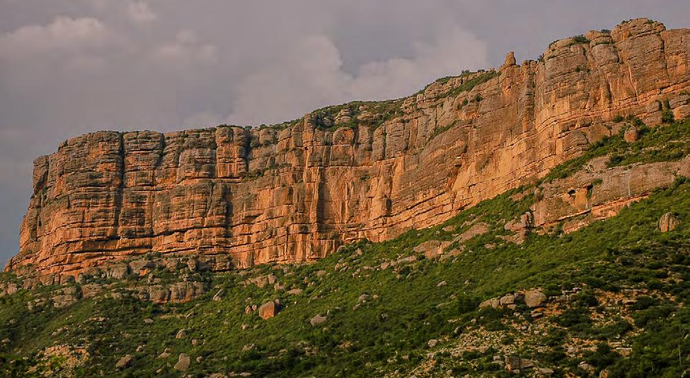

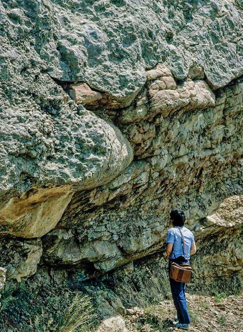
CHAPTER III TURBIDITE SYSTEMS: AN OUTCROP-BASED ANALYSIS 326
Fig. 350 - Alluvial fans: Element A – Close-up of thick gravelly-flow deposits separated by sandstone intercalations (reddish). Note scours at the base of conglomerate bodies as well as within them. Poorly-defined bedding surfaces in the lower conglomerate unit suggest progradation to the right. Oligocene Ebro basin, south-central Pyrenees.
A B
Fig. 351 - Alluvial fans: Element A – A. stacking of gravelly-flow deposits. B. Large scour, partly deformed by loading, at the base of a structureless conglomerate. Eocene-Oligocene Pobla de Segur conglomerates, south-central Pyrenees.
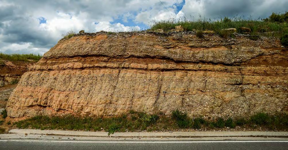
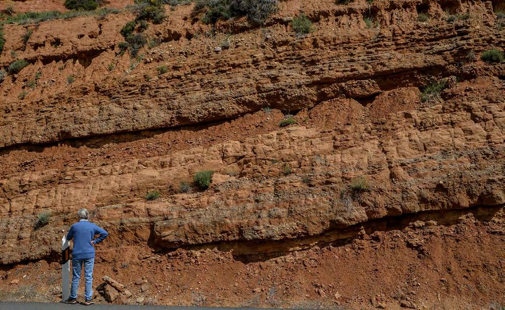
CHAPTER III TURBIDITE SYSTEMS: AN OUTCROP-BASED ANALYSIS 327
Fig. 352 - Alluvial fans: Element B – M-thick lithofacies made up of alternating conglomerate and sandstone separated by flood-plain mudstones. Conglomerates occur as lenticular units bounded by basal scours and transitionally or sharply capped by sandstone divisions. Oligocene Ebro basin, south-central Pyrenees.
Fig. 353 - Alluvial fans: Element B – M-thick fining-upward lithofacies sequences. The coarse-grained lower lithofacies consists of basal conglomerates forming irregular lenses that are either amalgamated or separated by thin sandstone divisions. These sediments are sharply or transitionally overlain by sandstone beds whose bedding geometry and internal structures are obliterated by pedogenesis. This coarse grained lithofacies is overlain by flood-plain fines. Oligocene Ebro basin, south-central Pyrenees.
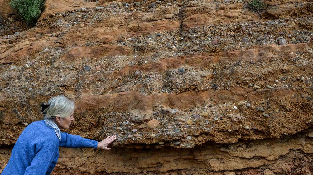
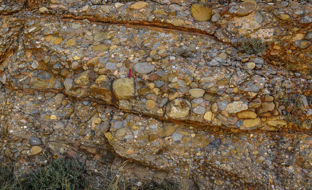
CHAPTER III TURBIDITE SYSTEMS: AN OUTCROP-BASED ANALYSIS 328
Fig. 354 - Alluvial fans: Element B – Detail of the basal conglomerates showing amalgamation and lenticularity of structureless conglomerate units each capped by a sandstone division. Conglomerate beds, which can be normally or inversely graded and most commonly structureless, are bounded by basal erosional surfaces that, in some cases, are clearly the product of small-scale cyclic steps. Oligocene Ebro basin, south-central Pyrenees.
Fig. 355 - Graded, clast-supported conglomerate division comprising almost the entire thickness of a flood unit. The dashed line indicates multiple grading produced by distinct gravel waves. Red arrow indicates the sharp contact (bypass surface) with an overlying thin sandstone division. Oligocene Ebro basin, south central Pyrenees.
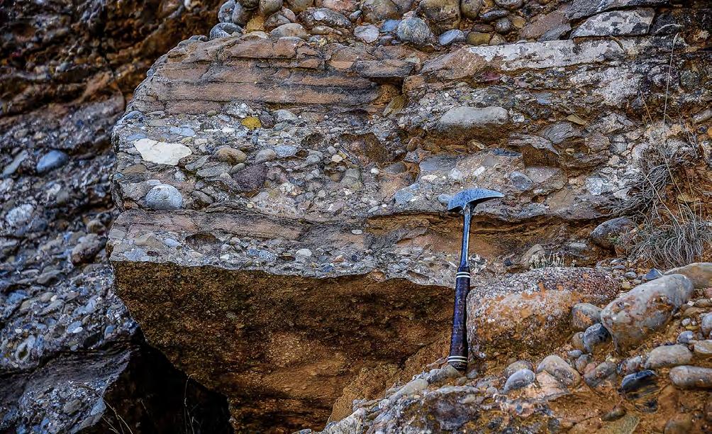
A terminal sandstone lobe, or element C, consisting of roughly tabular, m-thick sandstone packets separated by muddier facies (Figures 357 to 361). Each packet, or lobe, is made up of graded sandstone beds displaying an overall tabular geometry locally modified by scouring and compensation features. The thickest beds usually contain small pebbles infilling internal scours or being aligned in traction carpets (cyclic steps; see Figure 360). Most commonly, these beds are dominated by structureless divisions. The similarities with turbidites of F2 group (see Chapter II) are impressive. Above the structureless division, sandstone beds may display crudely laminated divisions and, in some cases, HCS (Figure 361). The significance of HCS is discussed in the following sections.
A distal element, or element D, made up of fine-grained facies deposited by trailing turbulent suspensions in the distal regions of terminal flood basins Element D is made up of alternating thin-bedded and fine-grained sandstones and mudstones in parallel-sided beds, i.e., the distal deposit of turbulent suspensions, associated with relatively thick mudstone units and paleosols.
VIII.3.1.3 – Some concluding remarks
Mutatis mutandis, flood-dominated alluvial fans are essentially a subaerial analogue of a canyon-fed turbidite system in that both types of sedimentation include a main feeder channel that branches into shallower distributary channels that, in turn, feed more basinal sandstone lobes and their distal fringe. Also, the processes are very similar, being mainly controlled by the transition from dense gravelly flows into final, dilute turbulent suspensions via a series of facies types that are virtually identical. It is here thought that, except for the trailing turbulent suspensions, most of the sedimentation is dominated by supercritical dense flows. A good example of supercritical flow deposition is shown in Figures 363-365, where tabular lobes entering an ephemeral lake depict small cyclic steps with scours filled with structureless pebbly sandstone passing into thick wavy or low-angle upcurrent-dipping cross laminae.
CHAPTER III TURBIDITE SYSTEMS: AN OUTCROP-BASED ANALYSIS 329
Fig. 356 - Typical conglomerate/sandstone couplets deposited by bipartite sheet flows. Note the thick sandstone laminae produced by supercritical flows above the structureless conglomerate divisions. Oligocene Ebro basin, south-central Pyrenees.
Figure 362 shows an example of these sediments in an ephemeral lake.
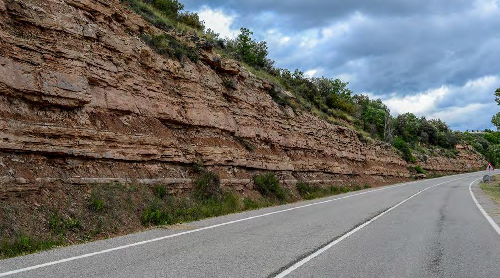
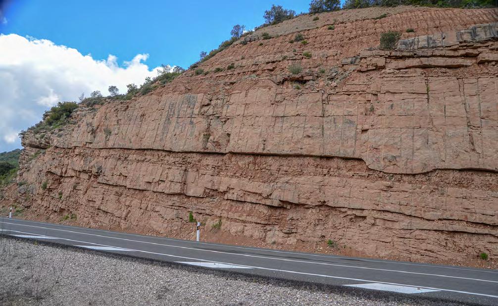
CHAPTER III TURBIDITE SYSTEMS: AN OUTCROP-BASED ANALYSIS 330
Fig. 357 - Alluvial fans: Element C - Sandstone lobe stacking in a terminal flood basin (ephemeral lake). Note the tabularity of individual lobes and the occurrence of well-defined thinning-upward sequences. Oligocene Ebro basin, south-central Pyrenees.
Fig. 358 - Alluvial fans: Element C - Terminal sandstone lobes. Note the fining- and thinning-upward sequences. Oligocene Ebro basin, south-central Pyrenees.
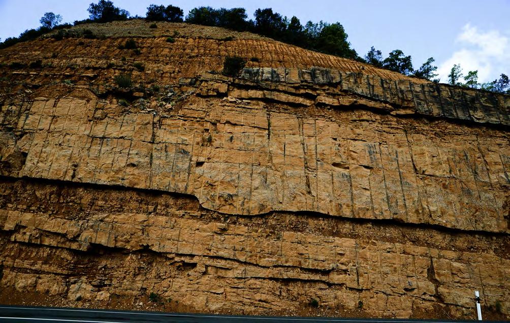
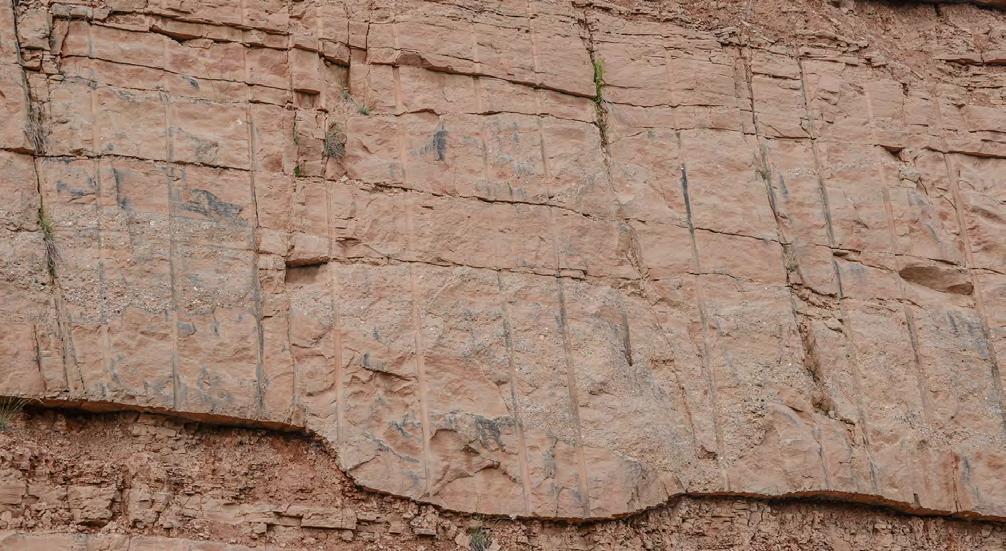
CHAPTER III TURBIDITE SYSTEMS: AN OUTCROP-BASED ANALYSIS 331
Fig. 359 - Alluvial fans: Element C - Sandstone lobes showing thick sandstone beds displaying multiple scours filled with small pebble conglomerate. Oligocene Ebro basin, south-central Pyrenees.
Fig. 360 - Alluvial fans: Element C -Close-up of a sandstone lobe of Figure 359 showing the overall thinning-upward of individual sandstone beds. Yellow lines indicate internal scours filled in with structureless pebbly sandstone (small cyclic steps). Paleoflow is approximately to the left. Total thickness is about 4m. Oligocene Ebro basin, south-central Pyrenees.
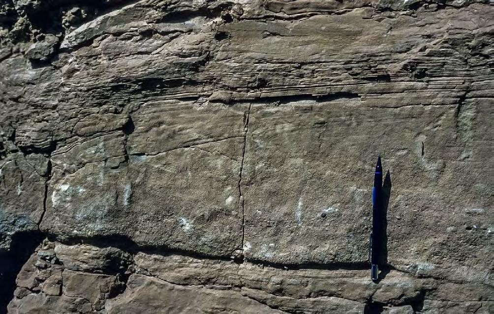
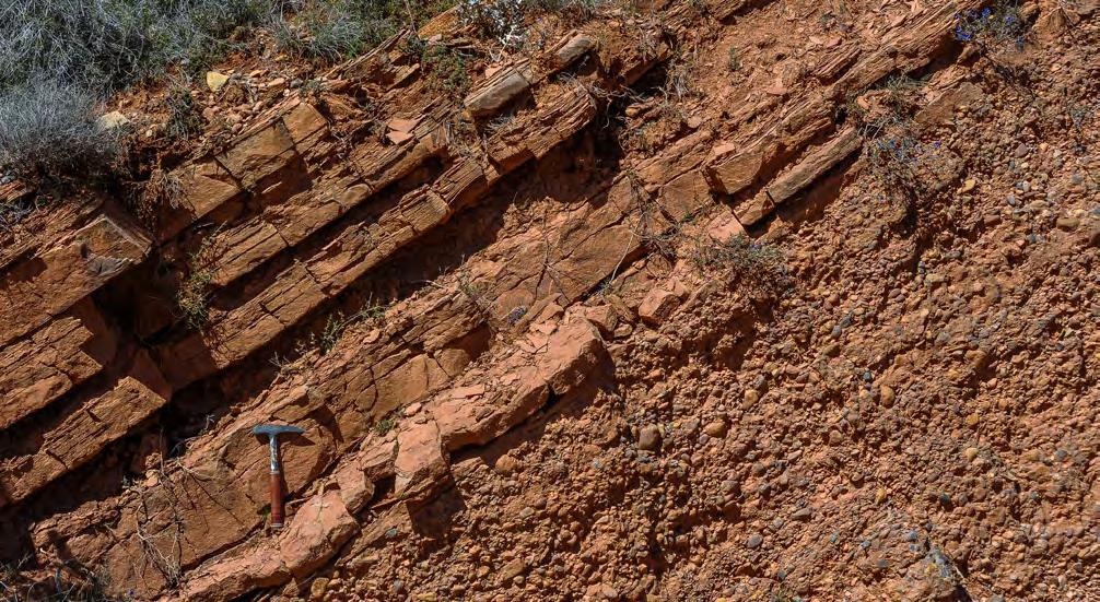
CHAPTER III TURBIDITE SYSTEMS: AN OUTCROP-BASED ANALYSIS 332
Fig. 361 - HCS above a division of coarse-grained graded sandstone with faint cross laminae and containing small pebbles at the base. Oligocene Ebro basin, south-central Pyrenees.
Fig. 362 - Alluvial fans: Element D - Medium-bedded fine-grained sandstones with parallel and ripple laminae deposited by turbulent suspensions. Paleocene-Eocene Ager Group, south-central Pyrenees.
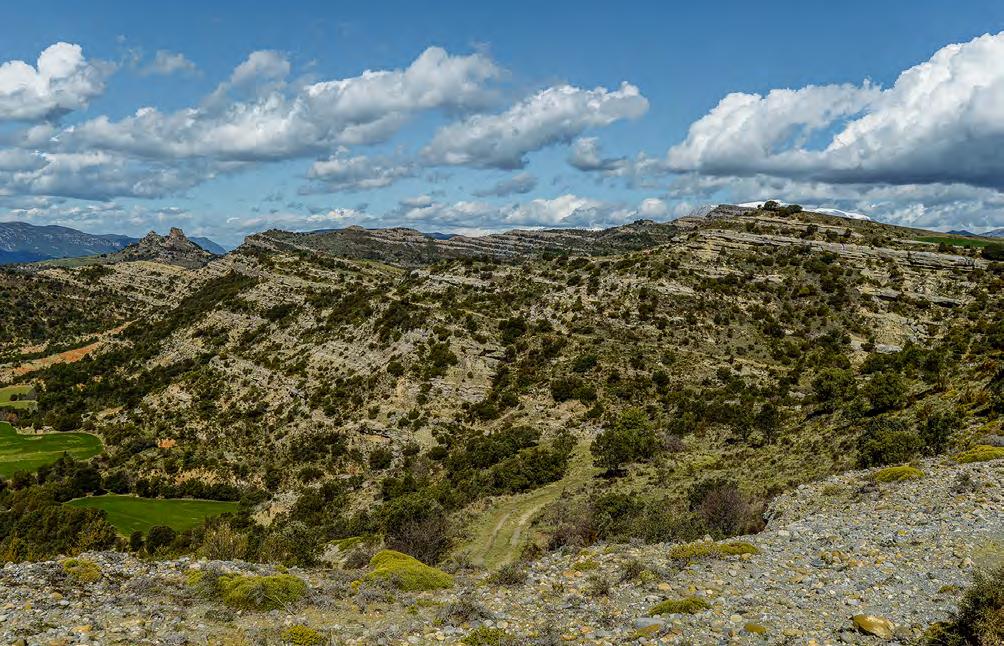
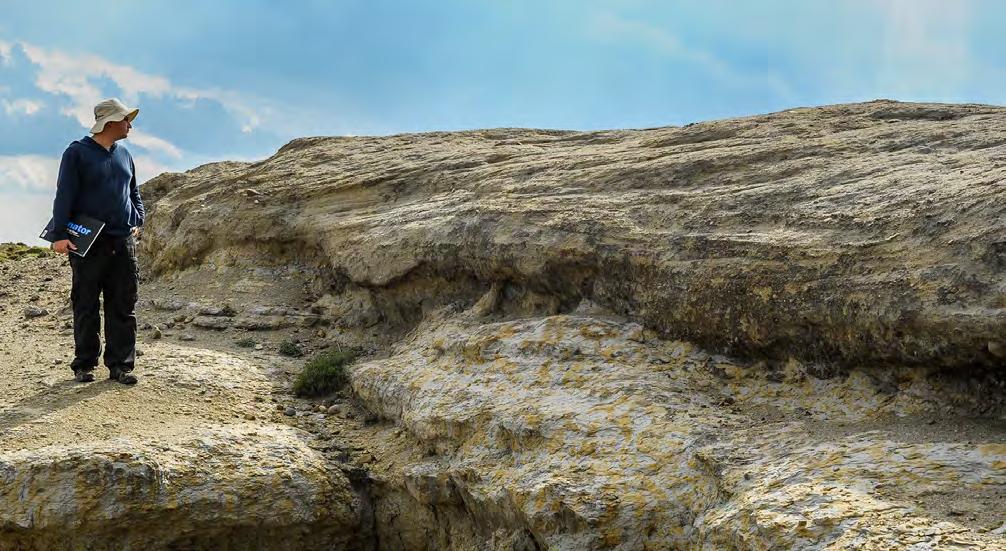
CHAPTER III TURBIDITE SYSTEMS: AN OUTCROP-BASED ANALYSIS 333
Fig. 363 - Tabular lobes of sandstone and conglomerates in an ephemeral flood lake. Eocene-Oligocene Cajegar basin, south-central Pyrenees.
Fig. 364 - Small cyclic steps in a sandstone lobe. The dip of the associated low-angle cross laminae is upcurrent. Main flow is actually from left to right. Eocene-Oligocene Cajegar basin, South-central Pyrenees.
Scours filled with structureless pebbly sandstone
Truncation surface
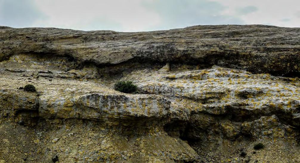
Flow direction
Upcurrent dipping low-angle cross laminae
The model suggested here (Figure 346) is a considerable departure from current models mainly based on modern examples, the main difference being primarily the ability of alluvial fans to transfer sand from drainage basins to distal low-gradient regions through sediment gravity flows, that is in absence of normal river processes. Transient and very surficial river-type processes certainly occurred, but their record was removed by subsequent floods.
Flood-dominated alluvial fans obviously differ in many other aspects from deep-water fans or turbidite systems for the simple reason that subaerial conditions imply a series of surface processes (e.g., overland flows) that cannot exist in deep-water. Though important for local detailed studies, features related to these processes are here omitted because of their limited general interest.
Some basic characteristics of these sediments that can be easily recognized in the field include:
• marked downfan decrease in channeling and scouring;
• increase in tabularity of sandstone bodies in the same direction;
• progressive increase in fine-grained intercalations;
• overall fining of grain size in a downcurrent direction, coupled with an increased sediment sorting;
• per vasive occurrence of m- to dam-thick lithofacies sequences characterized by thinning- and fining-upward trends of the component beds.
The above sediments characteristically stack in high-frequency m-thick fining- and thinning-upward lithofacies sequences which commonly culminate into flood-plain mudstones and paleosols. These finingand thinning-upward sequences are best explained as recording forestepping and backstepping cycles of gravel and sand deposition produced by flood-generated flows of progressively smaller-volume and efficiency, i.e., by a decreasing degree of catastrophism (see later).
A very good example of this type of sequence is provided in Figure 366 showing a small terminal fan lobe enclosed by flood-plain fines and paleosols. The basal lithofacies, sharply resting on a paleosol, consists of clast-supported, relatively well-sorted and locally cross-stratified pebble conglomerates forming a succession of amalgamated, roughly tabular or broadly lenticular beds with some preserved sandstone caps. Through a sharp contact, this facies is overlain by an alternation of thin-bedded, fine-grained and current
CHAPTER III TURBIDITE SYSTEMS: AN OUTCROP-BASED ANALYSIS 334
Fig. 365 - Detail of Figure 364 showing small cyclic steps. Scours generated by hydraulic jumps are filled with structureless pebbly sandstones that grade downcurrent into thick, gently upcurrent dipping cross laminae and wavy laminae produced by re-accelerating flows. Dashed blue lines indicate preserved laminae in a similar unit that underwent pedogenesis.
laminated sandstones and mudstones. The sequence is overlain by flood-plain mudstones and paleosols. The conglomerate lithofacies can be interpreted as the product of relatively unconfined gravelly sheet flows that underwent frictional freezing and were bypassed by dilute turbulent flows. When the volume of individual flood decreased, the system underwent backstepping, recorded by sand deposition. The example is from the same locality and the same stratigraphic unit of the sigmoidal bar of Figure 331. By integrating the facies of both examples, which are only a few tens of meters apart, the more general facies tract of Figure 367 can be reconstructed, allowing for a reasonable interpretation of the local facies association. This is a typical application of the approach based on facies identification and their re-assembling (see above) and is probably the most useful way to do facies analysis in outcrop studies.
VIII.3.2 – River deposits
As noted in previous pages, the stratigraphic record of tectonically active basins suggests that fluvial sedimentation was characterized by small- and medium-sized mountainous rivers as envisaged by Milliman and Syvitski (1992) for active margin settings. Major fluvial conduits, in most cases related to structural lineaments, were certainly present but their stratigraphic record has been removed by subsequent uplift and subaerial erosion. The preserved record mainly includes lenticular bodies of conglomerates, pebbly sandstones and sandstones enclosed by flood-plain fines. In previous literature, most of these bodies have long been interpreted as classic point bars and braided-stream deposits, especially in the south-central Pyrenees, and thus framed within the classic models of fluvial sedimentation of Miall (1985, 2006).
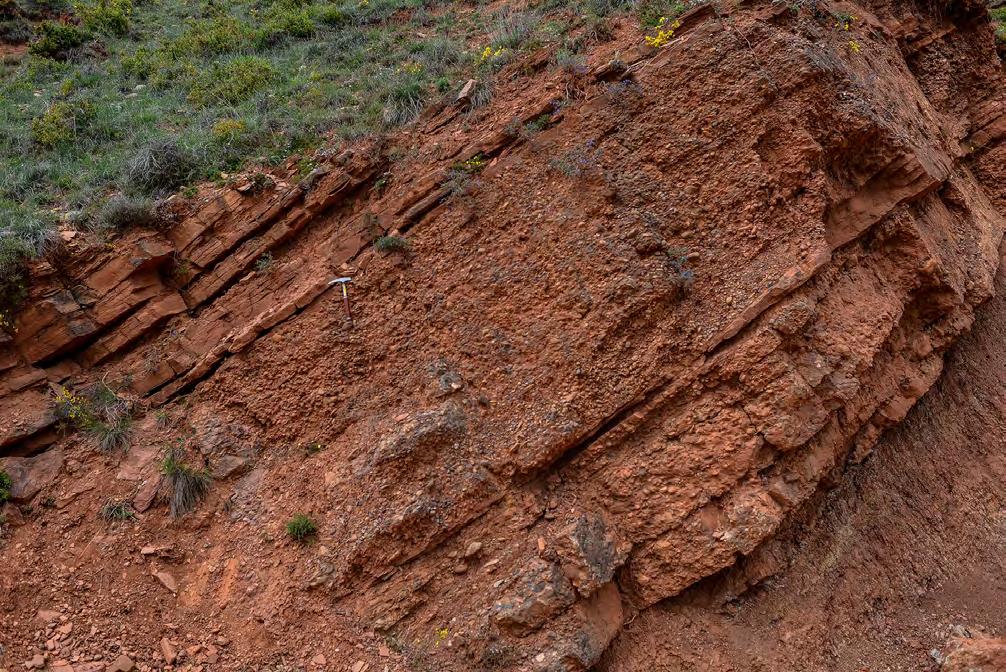
Sheet-flow deposits (amalgamated clast-supported conglomerates and conglomerate/ sandstone couplets)
Paleosol
CHAPTER III TURBIDITE SYSTEMS: AN OUTCROP-BASED ANALYSIS 335
Fig. 366 - Vertical facies sequence of a small terminal fan lobe enclosed by flood-plain fines and paleosols. The unit records deposition of an initial forestepping stage followed by a gradual reduction in the volume and momentum of flows. See text for an explanation. Paleocene-Eocene Tremp-Ager Group, south-central Pyrenees.
Dilute turbulent suspension deposits
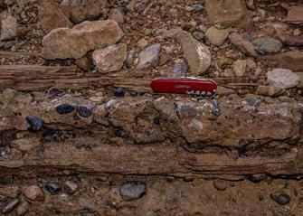
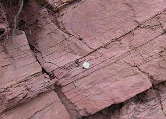
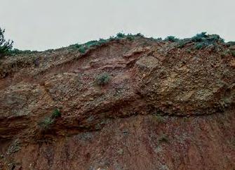
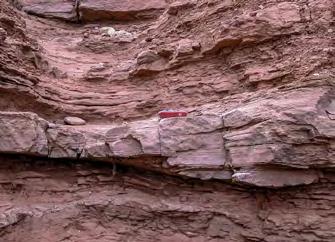
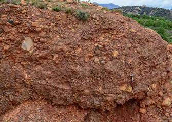
Flow direction
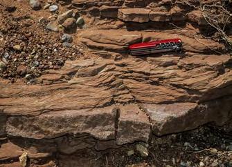
Below, an attempt is made to show that most of these bodies are in fact dominated by flood processes – an interpretation partly suggested by Mutti et al. (1996) and re-emphasized herein. The depositional elements dealt with below include:
Flood-dominated laterally accreting deposits, characterized by accretion of sandstone beds perpendicularly to the river course and forming point bars;
Flood-dominated vertically and downstream accreting deposits, characterized by the vertical stacking of graded flood units and complex conglomerate and sandstone barforms with downcurrent dipping cross strata.
VIII.3.2.1 – Flood-dominated laterally-accreting deposits
Meandering channel deposits are probably among the most popular and well-understood fluvial features, comprising sharp–based m–thick sandstone bodies, termed point bars, and laterally extensive meandering
channel belts in alluvial plains (see Collinson, 1996 for an extensive review). As shown in the sketch of Figure 368, the model of this kind of sedimentation is relatively simple and characterized by: (1) sharp-based, fining- and thinning-upward m-thick facies sequences; (2) lateral accreting master bedding surfaces, each representing an original depositional profile (time surface) dipping toward the erosive concave bank; and (3) a series of associated features including chute channels, scroll bars, levees, crevasse splays, and oxbow lakes. Development of meandering stream channels and their deposits is typical of mixed-load rivers (see above), where large amounts of fines are transported in suspension and sand is transported as bed load through traction processes. Thus, in classical facies sequences the sandstone bar includes a coarsegrained lag deposit recording erosion and deposition in the thalweg, followed upward by trough cross-bedded sandstone produced by migrating dunes, in turn capped by ripple-laminated sandstone with increasing suspended-load features (climbing ripples) that grade upward into flood-plain fines. Parallel-laminated sandstone are also common. The sequence is easily explained through flow deceleration along the oblique
CHAPTER III TURBIDITE SYSTEMS: AN OUTCROP-BASED ANALYSIS 336
A D C F B E
Fig. 367 - Reconstructed facies tract. A – Poorly sorted, matrix-supported conglomerate; B – Relatively well-sorted cross-stratified conglomerate; C – Thin conglomerate division overlain by climbing ripples; D –Thin, medium-grained sandstone division overlain by laminated sandstone; E - Medium- to fine-grained sandstone with HCS; F – Very fine-grained sandstone with horizontal and ripple laminae. Note the downcurrent transition from gravelly dense flow to turbulent suspension deposits.
depositional surface that on the convex side of the bar connects the flood plain to the thalweg.
Bars of this type also occur in fluvial systems of orogenic belt basins, though mostly restricted to delta-plain settings where tides affect rivers and force them to meander. Such conditions are usually met during periods of sea level rise (see later). A typical example of this kind of setting is shown in Figure 369. The geometry of the point bar fits perfectly the model of Figure 368, but the basal facies is strongly influenced by tides with the development of mud couplets (Figure 370).
Flood-dominated point bars are also m-thick bodies which are very similar to normal point bars as to external geometry and internal lateral-accretion surfaces (Figure 371). However, they differ substantially in terms of component beds. The lateral accreting beds are one-event beds, each deposited by a sediment gravity flow with very distinct vertical and up-slope grading. Vertical grading results from the waning of the flow through time; up-slope grading results from flow deceleration while the flow is ascending the slope of the convex bank. These beds tend to form amalga-
mated packages of sandstone and very poorly sorted pebbly sandstone showing multiple grading in the basal portion of the bar, whereas they become current-laminated and separated by mudstone partings in the upper one. In this upper portion lateral accretion surfaces are thus very clearly expressed and sole markings may be common at the base of many sandstone beds (Figure 372). Flood-dominated point bars also differ as to the character of their basal surface. In normal point bars, this surface, which is produced by lateral thalweg migration, is typically sharp and flat because the river does not undergo substantial variations in its discharge. In flood-dominated point bars the surface is conversely highly irregular, with deep and irregularly distributed scours produced by major flood events (Figure 373).
These bars, which could be a very interesting analogue for a better understanding of deep-water meandering channels, occur as isolated bodies within flood-plain mudstones or late-stage, minor flood events on top of thicker and more laterally extensive sandstone units deposited by larger-volume floods.
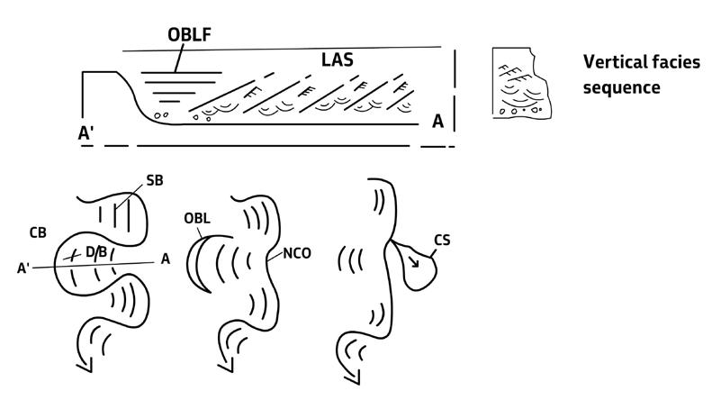
CHAPTER III TURBIDITE SYSTEMS: AN OUTCROP-BASED ANALYSIS 337
Fig. 368 - DB – Depositional (convex) bank; CB – Concave (erosive) bank; NCO – Neck cutoff; OBL – oxbow lake (abandoned channel); CS – Crevasse splay; B – Scroll bars; LAS – Lateral accretion surface; OBLF – Vertically-accreting fill of oxbow lake (through overbank processes).
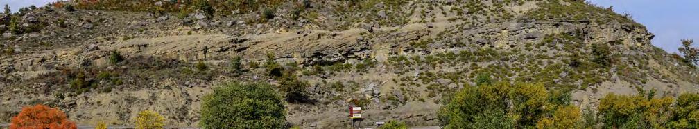
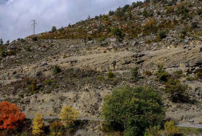
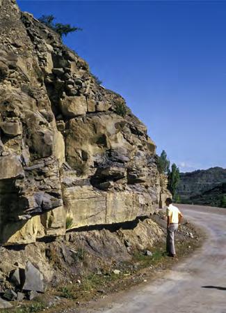
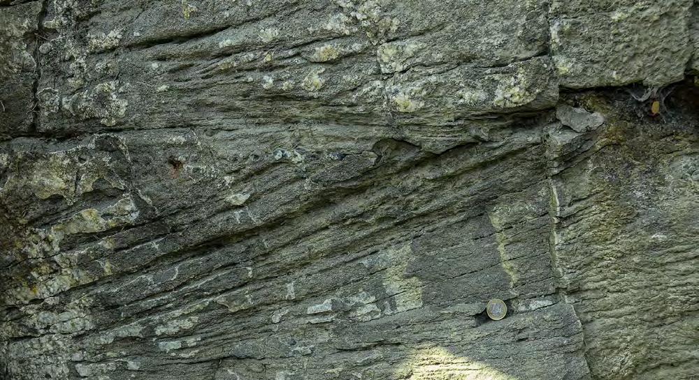
CHAPTER III TURBIDITE SYSTEMS: AN OUTCROP-BASED ANALYSIS 338
Fig. 369 - The well-known point bar of Puente de Montanana, Eocene Castigaleu Group, south-central Pyrenees (Puigdefabregas and Van Vliet, 1978; Bosellini et al., 1989): The deposit shows evidence of tidal action at its base. Main flow is toward the viewer. Note the FU facies sequence expressed by the weathering profile.
Fig. 370 - Detail of Figure 369 showing tidal mud couplets at the base of the point bar.
FU facies sequence
Lateral accretion surface
Shalying out of talweg sandstones toward mudstones of depositional bank (lateral facies change)
Lateralaccretionsurfaces
Irregularly scoured basal surface
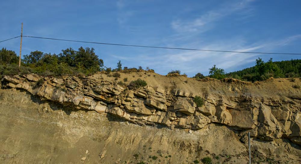
Scroll bar
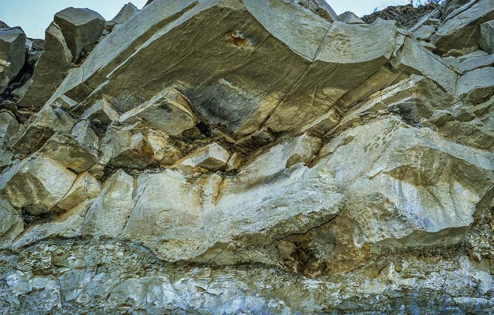
CHAPTER III TURBIDITE SYSTEMS: AN OUTCROP-BASED ANALYSIS 339
Fig. 371- Example of flood-dominated point bar. Note the irregularly scoured basal surface (compare with Figure 369) and the welldeveloped lateral accretion surfaces. Eocene Castissent Group, south-central Pyrenees.
Fig. 372 - Detail of Figure 371 showing the irregular basal surface and current marks, mainly tool casts, at the base of a lateral accreting flood unit. Paleoflow (red arrow) toward the viewer.
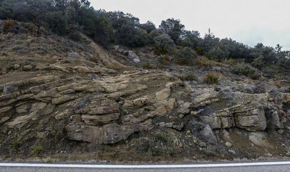
VIII.3.2.2 – Flood-dominated vertically and downstream accreting deposits
The lateral accreting flood-dominated deposits discussed above are certainly an important component element of many fluvial systems of orogenic belt basins, but the flows responsible for them are relatively small and essentially depositional. Therefore, they are not the best candidate to develop powerful and voluminous hyperpycnal flows when entering seawater. Conversely, these conditions are met by essentially bypassing flows that are responsible for limited deposition in the alluvial environment and can transfer to the sea a substantial portion of their sediment load. These flows, as discussed below, produce fluvial elements that are overlooked and/or misinterpreted in the literature and primarily described as pertaining to the broad family of “braided” stream deposits. On the contrary, these deposits are crucial to understand facies and flow types occurring and operating in the alluvial environment in those systems that produce substantial hyperpycnal-flow deposition in seawater.
The above sediments are extremely common in the exposed alluvial successions of orogenic belt basins displaying a great variety of lithologies, geometry and internal architecture. They range from small, highly lenticular bodies to large roughly tabular sheets characterized by facies types indicating deposition from bypassing flows of variable strength and duration. When examined in detail, these sediments appear as m-thick bodies, bounded by basal erosional surfaces and enclosed by flood-plain fines and paleosols. Each body consists of vertically accreted fining-upward flood units with individual thicknesses up to several meters thick primarily made up of coarse-grained facies left behind by passing, sediment-laden flows. Viewed in terms of “architectural” elements (sensu Miall, 1985, 2006) most of these sediments could be simply described as “gravel bars and bedforms” and “sandy foreset macroforms” (downstream accreting sandstone bars).
For the sake of simplicity, these sediments can be grouped in two intergradational elements: (1) gravelly river element and (2) sandy river element.
CHAPTER III TURBIDITE SYSTEMS: AN OUTCROP-BASED ANALYSIS 340
Fig. 373 - Example of a flood-dominated point bar. Blue lines indicate lateral accretion surfaces. Note that the main basal surface of the bar (white line) is truncated to the left by a deep scour onto which lateral accretion is resumed. The pale green line shows horizontally bedded flood-plain deposits. Eocene Castigaleu Group, south-central Pyrenees.
VIII.3.2.2.1 – Gravelly river element
The coarse-grained lithofacies of these bodies consists of basal conglomerate beds that can be either amalgamated or capped by thin and laterally discontinous sandstone divisions that are conspicuous for the general lack of classic fluvial bedload features typified by festoon cross-bedding. This coarse-grained lithofacies grades either sharply or transitionally, through an intervening sandstone unit, into overlying flood-plain fines.
The basal conglomeratic unit is made up of mostly clast-supported and poorly stratified or structureless conglomerates resulting from the amalgamation of several flood-units, or most commonly from the occurrence of conglomerate/sandstone couplets recording individual flood events or pulses within the same event (Figures 374-376).
In exposures parallel to current direction, most conglomerates appear to be crudely to fairly well cross stratified, allowing for a better understanding of the associated sandstone divisions (Figure 377). Thin sandstone divisions occur as highly discontinuous
units on top of individual conglomeratic cross strata; thicker sandstone units occur as parallel-laminated divisions forming the unconformable topset of underlying cross strata along a surface characterized by a major break in grain size (Figure 378). In the absence of these topset sandstones, sets of cross strata are directly superimposed one upon the other (Figure 379). Within individual sets, the dip of cross strata decreases in a downcurrent direction (Figure 377). Basically, bedding pattern geometry and facies characteristics indicate that deposition took place according to the microdelta scheme discussed in the preceding pages, that is through a basal and coarse-grained downstream accreting carpet sheared by a faster-moving and bypassing flow. The bypass surface is invariably marked by a major grain-size break (Figure 380). The process is further discussed below. In some instances, graded pebbly sandstone beds, with deeply scoured basal surfaces, occur as essentially horizontal intercalations within the above sediments. As shown in Figure 381, basal scours are apparently the result of cyclic steps.
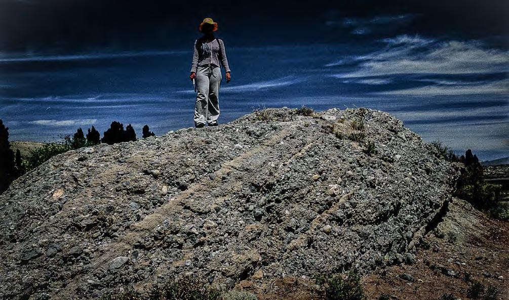
CHAPTER III TURBIDITE SYSTEMS: AN OUTCROP-BASED ANALYSIS 341
Fig. 374 - Example of gravelly river element made up of structureless conglomerates resting upon an erosional surface and separated by highly laterally discontinuous sandstone divisions. Jurassic, Neuquén basin.
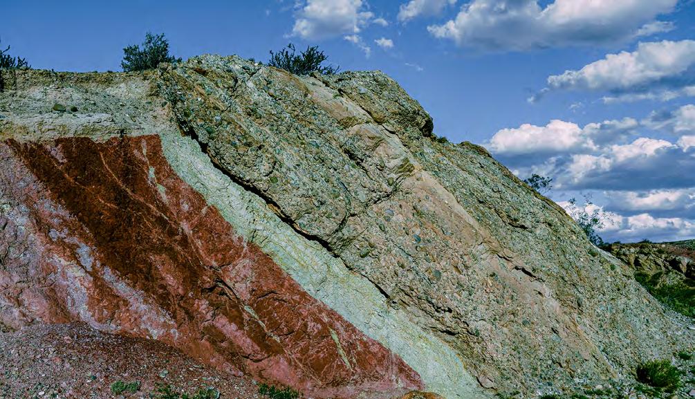
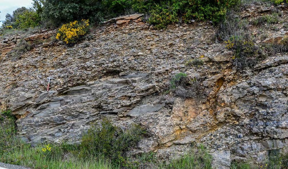
CHAPTER III TURBIDITE SYSTEMS: AN OUTCROP-BASED ANALYSIS 342
Fig. 375 - Fining-upward sequence (yellow line) resting on flood-plain fines and paleosols and truncated above by a new sequence. Note the basal unit consisting of broad lenses of conglomerate separated by thin sandstone division. A thicker and more tabular sandstone occurs at the top. Jurassic, Neuquén basin.
Fig. 376 - Irregularly-shaped flood units, each composed of a conglomerate/sandstone couplet. Conglomerate divisions are essentially structureless; sandstone divisions display low-angle cross laminae. Eocene Castigaleu Group, south-central Pyrenees.
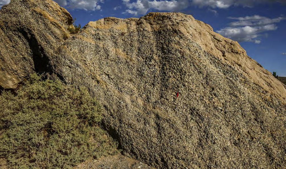
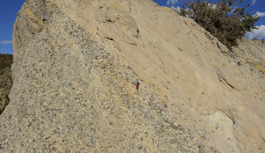
CHAPTER III TURBIDITE SYSTEMS: AN OUTCROP-BASED ANALYSIS 343
Fig. 377 - Flood unit (the base is indicated by red line) showing a basal conglomeratic division overlain by a sandstone division. The conglomerate division shows cross stratification enhanced by thin sandstone units. Note how dip of cross strata decreases upward. The upper sandstone division is characterized by parallel and wavy laminae. Upper Jurassic Lajas Formation, Neuquén basin.
Fig. 378 - Detail of Figure 377 showing the unconformable boundary between the lower, cross-stratified conglomeratic division and the horizontally stratified sandstone above. Note the break in grain size at the boundary and the sparse small pebbles along the parallel laminae of the sandstone division. The latter is interpreted as the deposit of vertically accreting antidune bedforms.
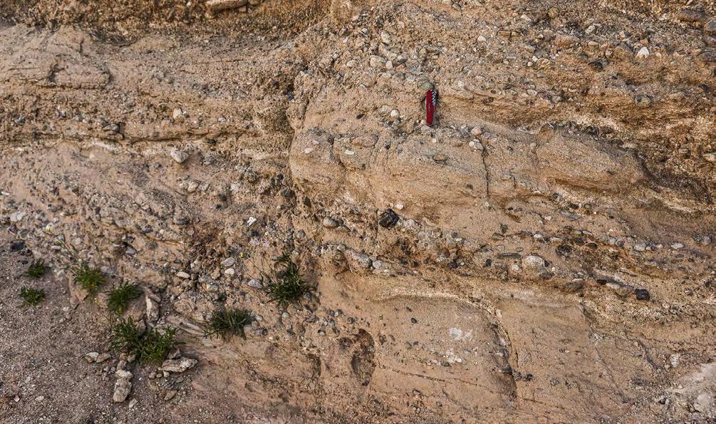
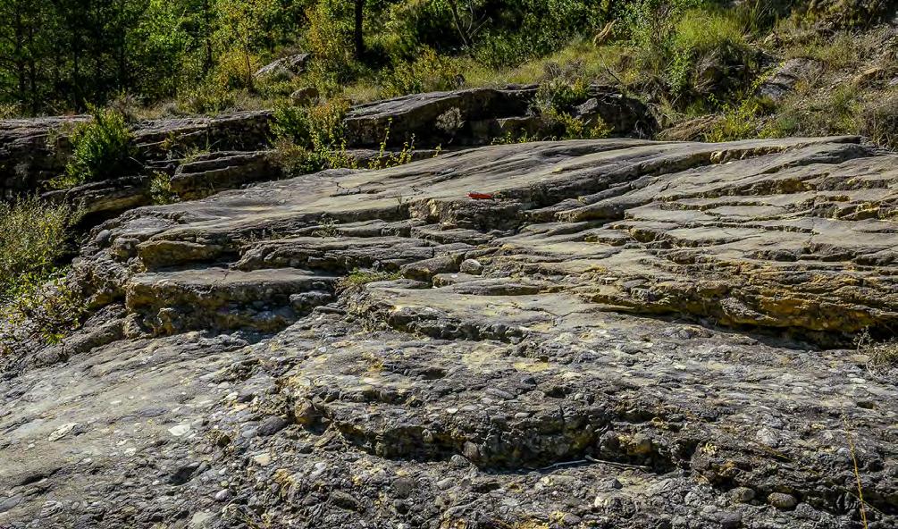
CHAPTER III TURBIDITE SYSTEMS: AN OUTCROP-BASED ANALYSIS 344
Fig. 379 - Two sets of downstream accreting very poorly sorted conglomerate/sandstone couplets. Note the lack of an intervening parallel-laminated sandstone at the top of the lower set. Jurassic, Neuquén basin.
Fig. 380 - Typical flood unit showing a sandstone division with low-angle and convex-upward cross laminae abruptly resting, through a grain-size break, on a thin conglomeratic division. Eocene Castigaleu Group, south-central Pyrenees.
Downstream accretion
Graded pebbly sandstone
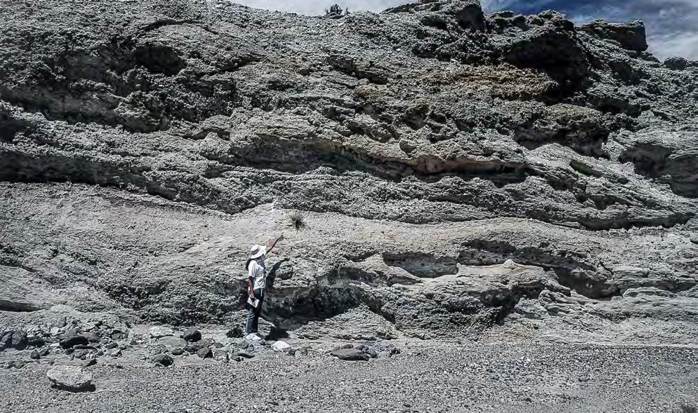
In both cross- and down-current direction, individual flood units are bounded by basal erosional surfaces and have an overall lens-shaped and a highly irregular geometry; their size varies greatly depending upon the magnitude of flood processes. Clearly, each of these unit indicates a basal coarse-grained lag followed by sediment by-pass and late flood-stage deposition. Overall, these channel-fill sequences indicate a gradual decrease of individual flood events until final cessation of fluvial activity.
This kind of fluvial deposits is generally interpreted as a braided-stream facies and according to Miall (1985, 2006) should record the complex interaction of highly mobile channels and bars in rivers of fluctuating regime, with sedimentation dominated by the “familiar flow regime bedforms” as described by many authors (Miall, 1985, p.276-277). This classic interpretation is here questioned on the basis of the sedimentary
structures observed in these sediments. The three basic features supporting flood processes and sediment gravity flows are: 1) the pervasive occurrence of conglomerate/sandstone couplets indicating the episodic character of deposition; 2) the lack of festoon cross-bedding or similar features ruling out the occurrence, or preservation, of tractive processes that would predominate during inter-flood stages; and 3) the association with genuine gravity flow deposits (see Figure 381) probably representing frozen parental flows.
This type of sedimentation suggests relatively small, coarse-grained and high-gradient fluvial systems entirely dominated by flood processes and characterized by substantial bypassing. If sufficiently large and longlived, these systems appear to be an ideal candidate to produce dense hyperpycnal flows that were able to carry coarse-grained sediments to shelfal and deeper-water regions seaward of coarse-grained deltas.
CHAPTER III TURBIDITE SYSTEMS: AN OUTCROP-BASED ANALYSIS 345
Fig. 381 - Downstream accreting conglomerate units in a gravelly river element. Note graded pebbly sandstones with basal scours and crude downstream accretion surfaces overlain by downstream accreting conglomerates. The upper part of the outcrop consists of crudely stratified conglomerates and sandstones. Jurassic, Neuquén basin.
VIII.3.2.2.2 – Sandy river element
These deposits, primarily consisting of sandstones and enclosed by flood-plain facies and paleosols, can be observed in composite bodies with thicknesses up to some 20 m and of considerable lateral extent. Very good examples of this kind of fluvial sedimentation are certainly the Eocene Castissent (Figure 382) and Corca units in the south-central Pyrenees (Mutti et al., 1996; Mutti, 2019) - two spectacular stratigraphic units to document flood events of great magnitude. Both units record the infilling of ephemeral fresh- or brackish-water basins produced by flooding in structurally confined settings. Downstream accreting bars characterize the proximal segments of these basins.
The internal structure of these bodies is characterized by the aggradation of graded, meter-thick flood units (Figures 383 and 384), with facies types indicating both bed load and suspended load transport. Individual flood units are commonly amalgamated through erosional surfaces or, more rarely, separated by mudstone divisions recording the dilute tail of each flood. Bed load deposition is recorded by largescale downstream accretion of conglomerate, pebbly sandstone and sandstone facies. Suspended load deposition is indicated by an abundance of parallel
and wavy lamination, and distal climbing ripple and mudstone facies.
The component facies of an ideally complete sequence include, from base to top, or in a proximal to distal profile:
Facies 1 – Cobbly and pebbly conglomerates with a sandy matrix forming cross-stratified divisions, up to a few meters thick, that typically rest on erosional surfaces (Figures 385-388). These conglomerates vary from very poorly sorted and crudely stratified units to well bedded and relatively better sorted divisions. Many cross strata consist of conglomerate/sandstone couplets. Out-size clasts of intrabasinal fine-grained deposits and paleosols may be common.
Facies 2 – Poorly sorted pebbly sandstones in cross-stratified meter-thick divisions usually bounded by shallow erosional surfaces (Figure 389). Pebbles tend to occur at the base of each division but are also common within laminae and along lamination surfaces. In some instances, liquefied units of randomly mixed pebbles and sand occur at the base of these units.
Facies 3 – Relatively well sorted, coarse to medium sandstone forming sets of cross laminae bounded by slightly erosional and gently downstream dipping sufaces with occasional small pebbles (Figures 390-392). Water escape features may occur.
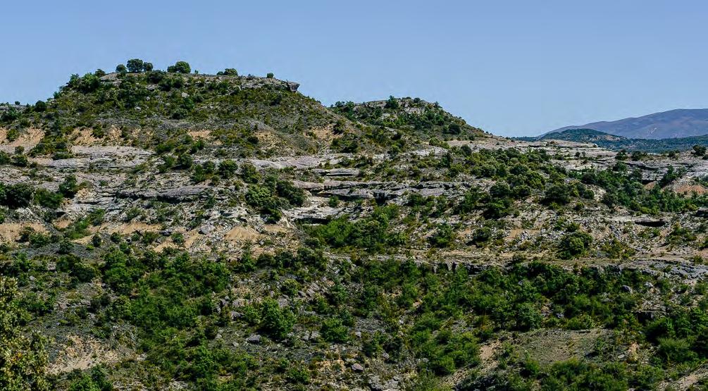
CHAPTER III TURBIDITE SYSTEMS: AN OUTCROP-BASED ANALYSIS 346
Fig. 382 - General view of one of the main fluvial sandstone bodies of the Eocene Castissent Group in the south-central Pyrenees. The body consists of stacked fluvial flood units.
Sandstone lithofacies
Flood-plain fines
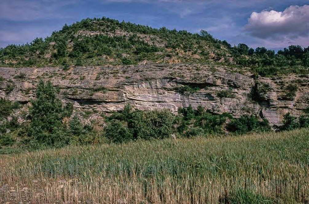
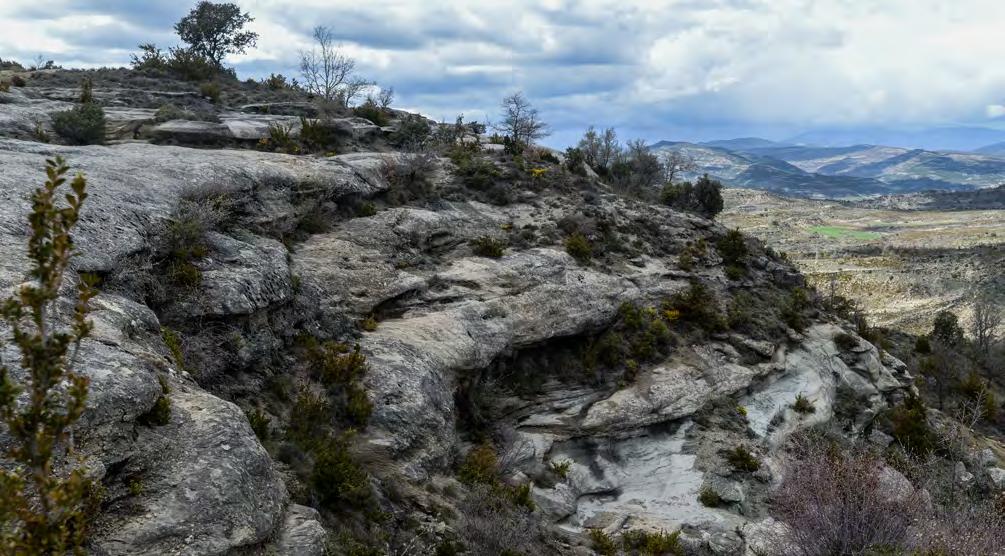
CHAPTER III TURBIDITE SYSTEMS: AN OUTCROP-BASED ANALYSIS 347
Fig. 383 - Two sandstone lithofacies separated by flood-plain fines and containing downstream accreting conglomerates and sandstone units. Yellow lines indicate erosional boundaries separating fining-upward flood units. Eocene Castissent Group, south-central Pyrenees.
Fig. 384 - Stacked fining-upward flood units bounded by erosional contacts (blue lines). Most units consist of downstream accreting sandstone bars, Eocene Castissent Group, south-central Pyrenees.
Out-size clast
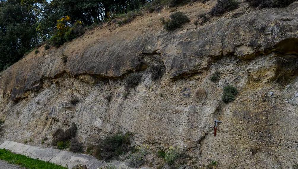
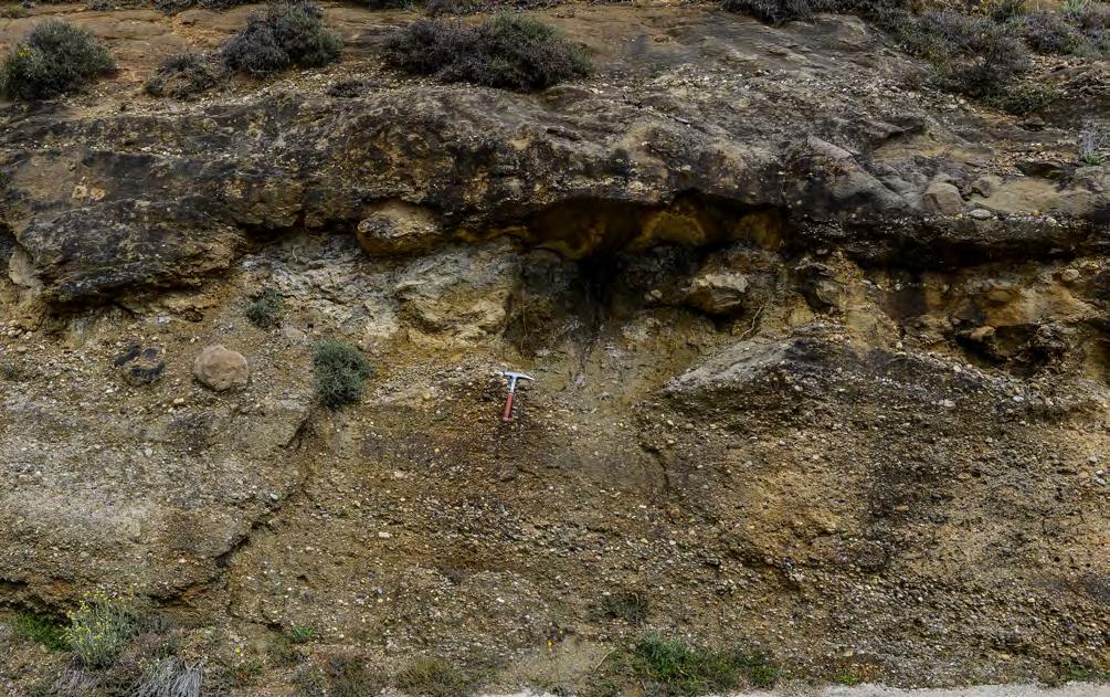
CHAPTER III TURBIDITE SYSTEMS: AN OUTCROP-BASED ANALYSIS 348
Fig. 385 - Graded flood unit consisting of a basal cross-stratified conglomerate overlain by cross-stratified sandstones and pebbly sandstones passing upward into a horizontally stratified sandstone. The contact (yellow line) is highly irregular due to out-size clasts floating at the top of the conglomerate division (though see Figure 386). Eocene Corca Sandstone, south-central Pyrenees.
Fig. 386 - Close-up of Figure 385 showing the boundary between cross-bedded conglomerates and the overlying pebbly sandstones. Note the out-size clasts (dashed red line) along the boundary. Alternatively, the out-size clasts could have been trapped in cyclic steps and be part of the overlying unit. In such case the cross laminae would dip upcurrent. Eocene Corca Sandstone, south-central Pyrenees (this spectacular and overlooked flood dominated unit would certainly deserve detailed sedimentological analyses).
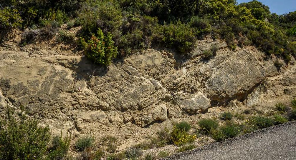
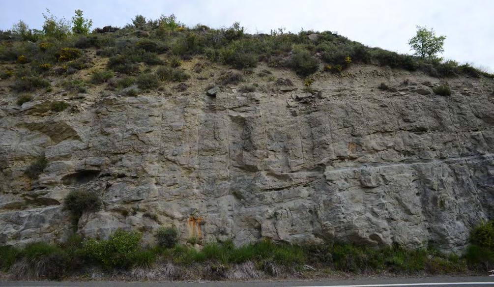
CHAPTER III TURBIDITE SYSTEMS: AN OUTCROP-BASED ANALYSIS 349
Fig. 387 - Cross stratified conglomerates and pebbly sandstones at the base of a thick flood unit. Flood pulses are recorded by sudden grain-size variations and local scours. Note the angle between the conglomerates and the overlying sandstone division. Eocene Corca Sandstone, south-central Pyrenees.
Fig. 388 - Flood units consisting of downstream accreting sandstones and pebbly sandstones resting upon erosional surfaces (yellow lines). Eocene Castissent Group, south-central Pyrenees.
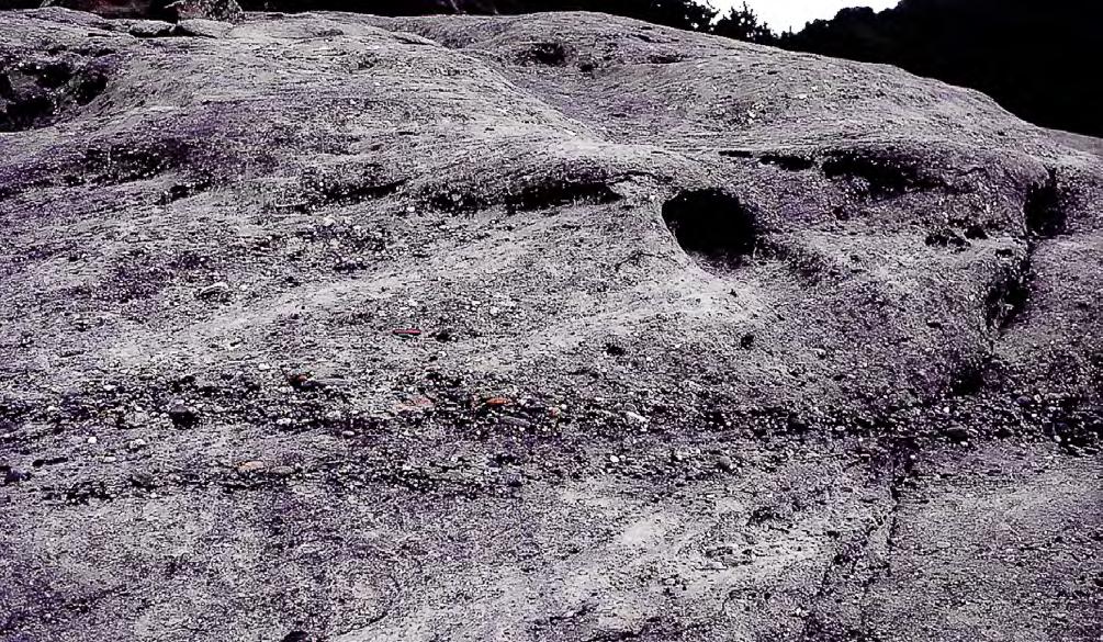
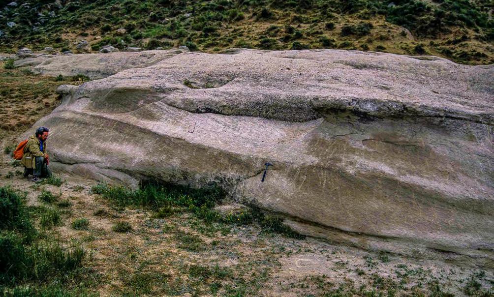
CHAPTER III TURBIDITE SYSTEMS: AN OUTCROP-BASED ANALYSIS 350
Fig. 389 - Cross-laminated pebbly sandstones. Note pebble concentration at the base of the unit and the upward transition of cross laminae into nearly horizontal laminae. Eocene Castissent Group, south-central Pyrenees.
Fig. 390 - Downstream-accreting sandstone showing stacking of thick laminasets separated by even surfaces gently dipping in the same direction. Eocene Castissent Group, south-central Pyrenees.
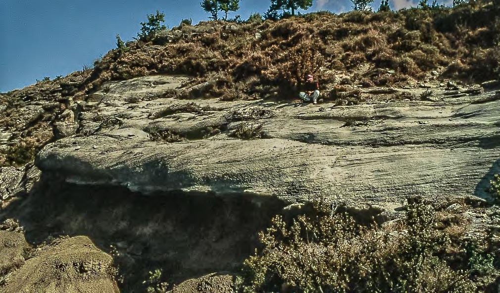
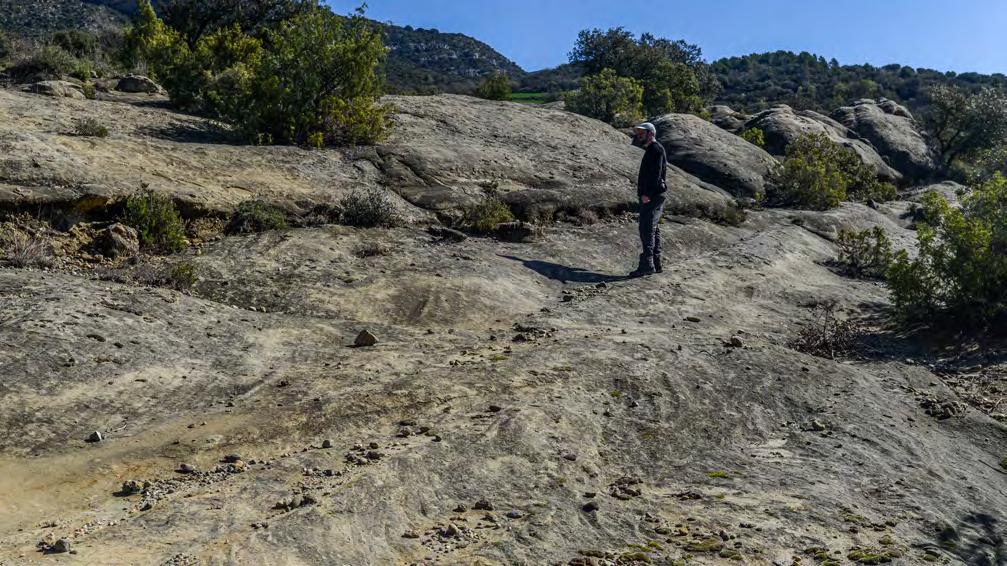
CHAPTER III TURBIDITE SYSTEMS: AN OUTCROP-BASED ANALYSIS 351
Fig. 391 - Downstream-accreting sandstone showing thick sets of gently dipping cross laminae. The basal erosional surface coincides with a major sequence boundary. Eocene Castissent Group, south-central Pyrenees.
Fig. 392 - Thick sets of cross laminae dipping to the left and bounded by sligthly erosional surfaces gently dipping in a downcurrent direction. Eocene Corca Sandstone, south-central Pyrenees.
Facies 4 – Well-sorted, coarse to medium sandstone with sigmoidal (convex-upward) laminae (Figure 393).
Facies 5 – Coarse to medium sandstone characterized by horizontal, wavy and low-angle cross laminae forming wedge-shaped sets separated by erosional surfaces that can be even or both convex- and concave-upward (Figures 394-396). Water escape features are commonly observed. Divisions of parallel laminae occurring in the upper portions of some flood units typically display the mm- to cm-tick repetition of thinning- and fining-upward sets thought to be produced by antidune of decreasing amplitude (Figure 397) (compare with similar features of turbidite F3 deposits, Chapter II).
Facies 6 – Fine to very fine sandstone characterized by climbing ripples (Figure 398). These ripples are typically capped by a mudstone division.
The above facies association indicates that deposition took place as shown in the scheme of Figure 399. Basically, the scheme shows a proximal zone of coarsegrained cross strata (microdelta) produced by a bypassing flow, a zone with sigmoidal laminae marking
the first deceleration of the bypassing flow with the beginning of vertical aggradation, and, farther downstream, the zone of deposition of the suspended load of the waning stage of the bypassing flow. As indicated by sedimentary structures, a large proportion of the deposition of suspended load was from supercritical turbulent flows under high rates of sediment fallout. The model is essentially that of a broadly lenticular sigmoidal bar with the development of a proximal microdelta (see above) resting upon an erosional surface. Deposition from waning subcritical turbulent suspensions, with the development of climbing ripples and mudstone caps, characterizes the distal zones. Each flood unit can thus be viewed as a fining-upward facies sequence recording the peak and the falling stage of an individual flood.
Microdelta cross stratified units display in rare instances an upper cap of true festoon cross-stratification followed upward by preserved megaripple and ripple bedforms (Figure 400). These sediments clearly record a final “clear-water” stage of the flood during which the flow partly reworked the underlying flood deposits through migrating dunes and ripples (Mutti et al., 1996).
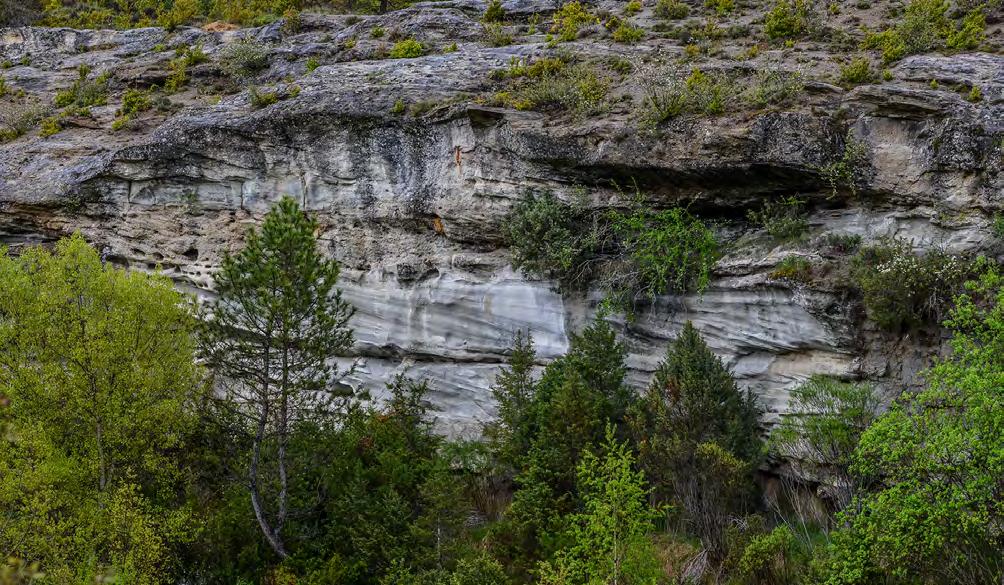
CHAPTER III TURBIDITE SYSTEMS: AN OUTCROP-BASED ANALYSIS 352
HL CGL T
Fig. 393 - Close-up of the lower sandstone lithofacies of Figure 383. Yellow lines show boundaries of flood units; blue lines show internal stratal surfaces. Note how the tangential (T) cross laminae of the lower flood unit become “healing” (HL), convex-upward laminae in a downcurrent direction (right) being overlain by topset horizontal strata. Eocene Castissent Group, south-central Pyrenees.
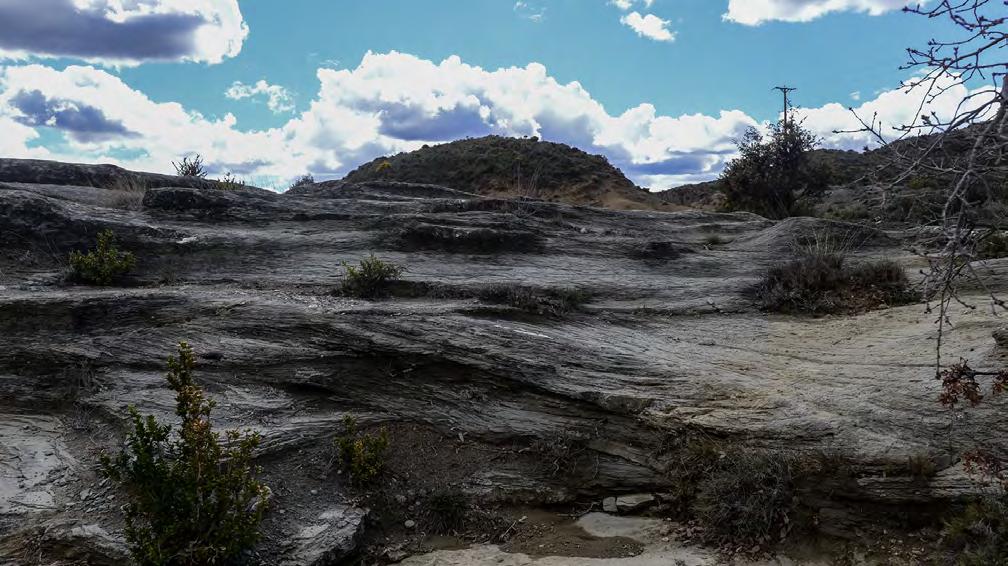
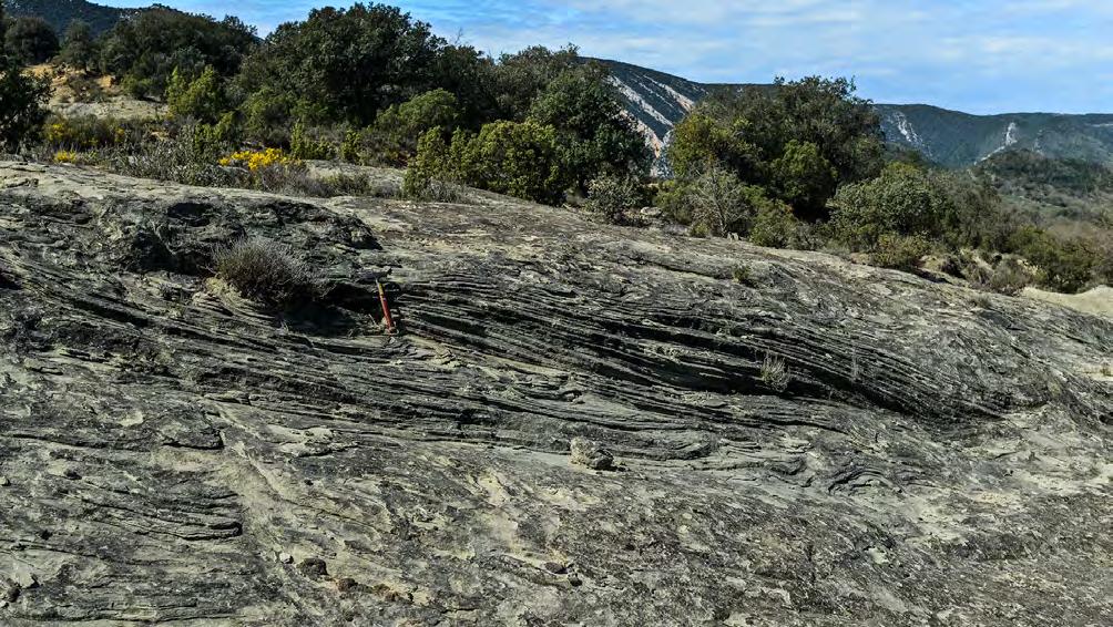
Convex upward
Set boundaries
Concave upward
CHAPTER III TURBIDITE SYSTEMS: AN OUTCROP-BASED ANALYSIS 353
Fig. 394 - Wavy-laminated sandstone (above) draping lenticular cross-bedded coarse-grained units. The sequence suggests chute and pool features overlain by antidune bedforms. Eocene Castissent Group, south-central Pyrenees.
Fig. 395 - Sandstone lamina-sets with complex geometry. Note wedge-shaped sets bounded by low-angle erosional surfaces and sets of broadly both convex- and concave-upward laminae. These features are thought to be the product of chute-and-pool bedforms. Eocene Corca Sandstone, south-central Pyrenees.
Late-stage ripples
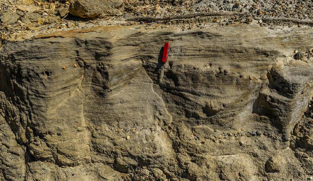
Flow direction
Supercritical structures
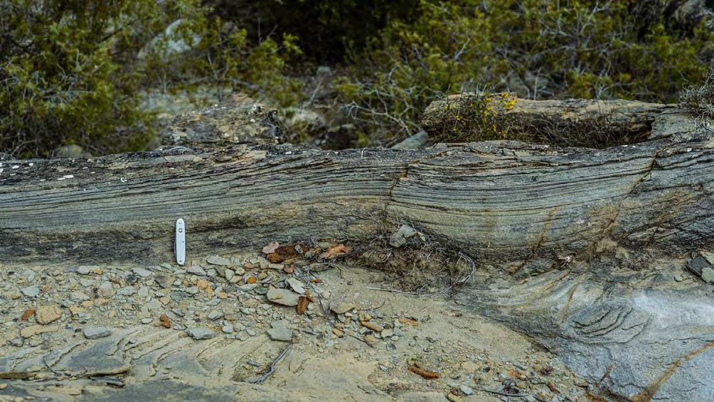
CHAPTER III
SYSTEMS:
OUTCROP-BASED
354
TURBIDITE
AN
ANALYSIS
Fig. 396 - Uppermost part of a flood unit showing late-stage ripples overlying a laminated sandstone division with internal erosional surfaces and wedge-shaped laminasets (chute-and-pool features?). Eocene Corca Sandstone, south-central Pyrenees.
Fig. 397-Nearly horizontal laminae at the top of a flood unit. Laminae are grouped into thin fining-upward lamina-sets each produced by the decreasing amplitude of an antidune. Compare with similar turbidite facies (Chapter II). Eocene Corca Sandstone, south-central Pyrenees.
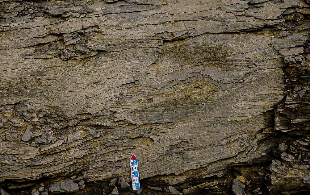
Bypassing flow
Bypassing flow
Final deposit
Downstream accreting microdeltas
Conglomerates
SL STAGE 1
SL
STAGE 2
STAGE 3
Aggradation from suspended load Healing stage
Sandstones and pebbly sandstones
Sandstones Fines
Grain size decreases
* No scale involved
CHAPTER III TURBIDITE SYSTEMS: AN OUTCROP-BASED ANALYSIS 355
Fig. 398 - Typical climbing ripples produced by high-rate of sediment fallout from a turbulent subcritical suspension. Eocene Castissent Group, south-central Pyrenees.
Fig. 399 - The supercritical bypassing flow changes into subcritical flow in a downstream direction as well as with time, depositing finegrained sandstones with climbing ripples and mudstones.
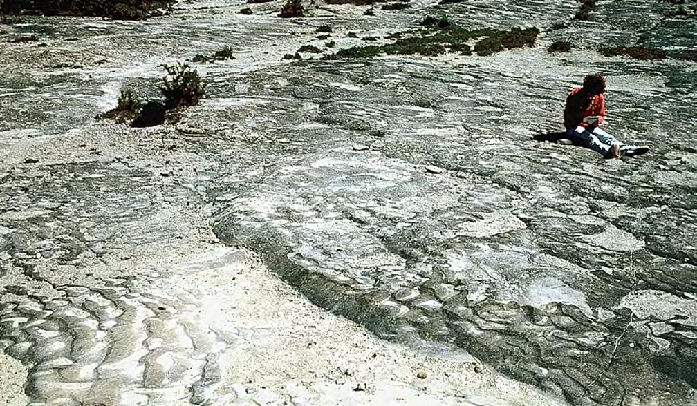
Though at a very small scale, the depositional pattern outlined above suggests a comparison with the huge bedforms of the modern Brahmaputra braided river (Coleman, 1969) where giant downstream accreting sand bars move seaward during high-river stages (monsoon season), being reworked and eventually capped by suspended load deposits when the discharge declines. At low-river stages, part of the sand bars and their finer-grained caps can be observed, showing the very complex architecture of these sediments in both downcurrent and cross-current direction. This complexity cannot be resolved in outcrop studies for the general lack of sufficiently large 3-D exposures and therefore the architecture of similar ancient deposits can only be schematically reconstructed along an ideal downcurrent direction.
The Brahmaputra river, the way it appears, has certainly a sandy braided pattern and the same pattern was certainly that displayed by our sediments if viewed in an inter-flood stage. Nonetheless, in both cases the systems are fundamentally driven by bypassing tur-
bulent flows that carry their suspended fine-grained load in a basinward direction. The cross-bedded sand dunes of the Brahmaputra and the cross-bedded conglomerates and sandstones of the Eocene Castissent and Corca units of the south-central Pyrenees (herein interpreted as microdelta features) have the same significance of residual sediments left behind by bypassing flows. A clear distinction should be made between braided patterns depicted by channels and gravel and sand bars produced by normal processes in river systems that are deficient in fines and braided patterns conversely produced by flood-generated downstream accreting microdeltas sheared by sustained bypassing flows loaded with fines. The same problem arises from the gravelly elements discussed above. Once again, all these features must be intergradational and controlled, among others, by the type of sediment supply, climate, and flood discharge and duration.
The sandy elements discussed above appear to be an excellent candidate to develop plunging plumes loaded with fine sand, silt and clay if flows can reach seawater.
CHAPTER III TURBIDITE SYSTEMS: AN OUTCROP-BASED ANALYSIS 356
Fig. 400 - Lower-flow regime (subcritical flow) megaripples and ripples at the top of a flood unit. These features are thought to be the product of bedload transport during the final “clear water” stage of the flood. Eocene Castissent Group, south-central Pyrenees.
VIII.3.3 – Delta front and prodelta elements
VIII.3.3.1 – General
When entering seawaters or lakes, both alluvial fans and rivers give way to sediment accumulations that represent three basic depositional elements of the general fluvial system as envisaged by Schumm (1981). For reasons of convenience, the following discussion is mainly based on marine settings. The proximal element forms at channel exits, i.e., near the shoreline (channel-exit element); the intermediate element forms seaward of the shoreline, in nearshore and shelfal regions (sandstone lobe element); and the distal element forms farther seaward, in outer shelf and slope regions (prodeltaic and delta-slope elements).
All the above elements are deposited by originally subaerial flood-generated flows that, entering seawaters, keep moving seaward as hyperpycnal flows. The channel-exit element forms from sudden deceleration suffered by the subaerial flow when entering seawater and can be viewed as a residual deposit left behind by overpassing flows or as a depositional feature formed during periods of reduced flood strength; the sandstone lobe element is the deposit of the coarse-grained load (gravel and sand) of the hyperpycnal flows; and the prodeltaic element is the distal and fine-grained depositional zone of these flows characterized by dominantly muddy deposits.
The basic distinction between flood-dominated fan-delta and flood-dominated river-delta systems (Mutti et al., 1996) is based upon the upcurrent stratigraphic relationships of lobe elements (Figure 401). In fan-delta systems, lobes grade into alluvial fan deposits through a transitional zone of difficult identification (or, better, a zone which is still poorly known at present), probably because subaerial flows enter seawaters being partly unconfined. In river delta systems, lobes grade into sandstone bodies formed at river mouths and showing complex depositional patterns (see later). For reasons of convenience, the term “channel-exit element” is maintained for both settings.
The distinction between fan-delta and river delta depositional elements is also supported by different facies characteristics and inferred processes. Fan-delta systems are the typical deposits of coarse-grained dense flows because of their higher gradients and proximity of the drainage basins to the shore zone (see above). River delta systems are instead the domain of turbulent plunging plumes loaded with fine-grained suspended load (< medium sand), indicating more mature fluvial systems where the coarse-grained sediment has been trapped in alluvial and deltaic plains. It should be kept in mind that this distinction is quite clear if dealing with the two end members. In the real world, most flood-dominated fluvio-deltaic systems are gradational between these two end-members.
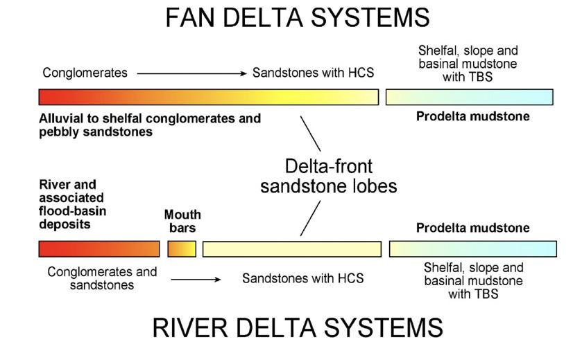
CHAPTER III TURBIDITE SYSTEMS: AN OUTCROP-BASED ANALYSIS 357
Fig. 401 - Elements of flood-dominated fan delta and river delta systems. Sandstone lobe and prodeltaic mudstone-dominated deposits are common to both types of system (from Mutti et al., 1996).
VIII.3.3.2 – Channel-exit deposits
The only type of channel-exit deposit we are familiar with is represented by the classic features that we can observe at modern river mouths. In river delta settings, these features, termed river mouth bars, consist of prograding sand bodies characterized by an offlapping geometry produced by the shore-line break (see delta-scale clinoforms of Patruno and Helland-Hansen, 2018). The characteristics of these features vary greatly as a function of the water depth of the receiving basin and particularly of the textural characteristics of river outflows. Rivers dominated by suspended load tend to form low angle clinoforms primarily composed of fine-grained sediment (Wright, 1977), whilst small coarse-grained rivers have the tendency to form Gilbert-type mouth bars, with high-angle clinoforms and well defined topsets, foresets and bottomsets.
If we consider the shorezone of modern fan-deltas and river deltas it is very easy to recognize what happens at the shoreline. In most cases, a beach separates alluvial fans from their subaqueous extension (fan-delta front), and various types of river mouths separate a river from its delta front in fluvial-, tide- and wave-dominated settings (see above). This is what happens in
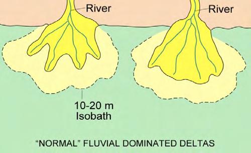
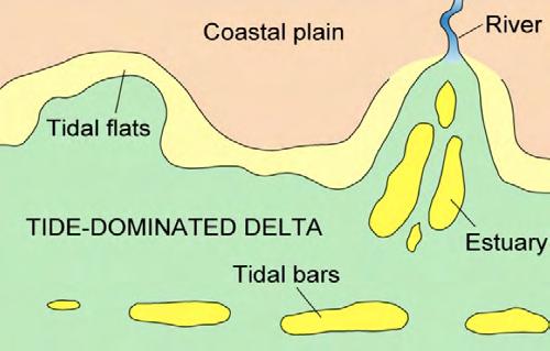
“normal” conditions. Conversely, when alluvial fans and rivers are dominated by flood processes during periods of time sufficiently long to leave their signature, the shorezone undergoes a dramatic change in terms of processes and configuration. The shoreline clearly remains as the basic divide between the continental and marine domains, but powerful flood-generated flows are short-lived events that have enough momentum to escape substantial modifications imparted by marine diffusion processes and keep moving seaward as dense hyperpycnal flows or plunging plumes. For this reason, flood-dominated fan-deltas and river deltas build most part of their delta-front elements in shelfal regions, thus differing from normal deltas (Figure 402). The deceleration of river outflows produced by their impact with a standing body of water must force erosion, partial deposition or modifications of these flows in the shore zone. Unfortunately, little attention has been given to this problem in the available literature. In particular, settings dominated by dense gravelly outflows remain essentially undescribed. With the general term of channel-exit deposits we tentatively discuss hereafter some of the settings that may develop in the shorezone of both river deltas and fan-deltas.
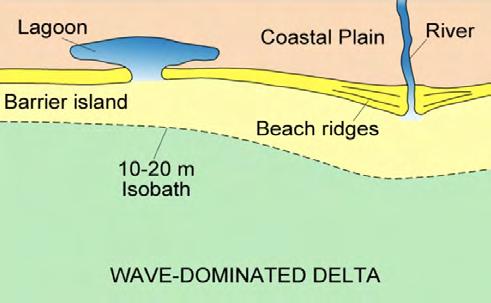
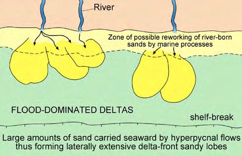
CHAPTER III TURBIDITE SYSTEMS: AN OUTCROP-BASED ANALYSIS 358
A C B D
Fig. 402 - Conventional models of fluvial- (A), wave- (B) and tide- (C) dominated deltas. (D) – Most flood-dominated deltaic deposits are preserved away from the littoral zone and in relatively deeper waters. In this zone, these deposits have a much higher preservation potential than in the more marginal ones. The basic difference between normal and flood-dominated deltas resides in the location of the main depositional zone of sandstone facies. In flood-dominated systems most of the sand is deposited by hyperpycnal flows in shelfal regions well beyond the depth reached by normal marine diffusion processes (waves and tides), thus increasing its preservation potential.
VIII.3.3.2.1 – Channel-exit deposits of river-deltas systems
Two basic types of river-exit deposits can be recognized: 1) bypass mouth bars, and 2) depositional mouth bars. Bypass mouth bars are typical of flood-dominated systems and are time-equivalent of shelfal sandstone lobes; depositional mouth bars are basically the same, though developed at a smaller scale, as those of modern deltaic systems dominated by fluvial processes.
Bypass mouth bars form wherever sand-laden turbulent flows with sediment concentration sufficient (35-40 kg/cubic meter) to exceed that of seawater at river mouths. In the model of Mulder and Syvitski (1995) these flows contain only fine sediment (< medium sand) that is entirely supported by turbulence. Though suspended load is predominant, the small and medium-sized rivers of tectonically active basins most commonly carry to the sea also a smaller proportion of coarse-sediment as dense, liquefied flows or as tractional bedload features (see above). Entering seawater, these sand-laden flows suffer deceleration and start depositing their excess sediment load which is bypassed by a turbulent flow. A first and preliminary attempt to describe this kind of setting was offered by
Mutti et al. (2000) who showed models of river mouth bars originated by both sediment-laden stream flows (Figure 402 A, 1) and composite dense flows (Figure 402 A, 2). At least to my knowledge, the best interpretation of bypass and depositional processes at a river mouth bar remains that of Tinterri (2007) in his study of the Roda Sandstone, south-central Pyrenees, a river delta partly affected by tidal reworking. The scheme offered by the author is shown in Figure 403, depicting a very clear separation in a bedload, a trailing suspended load (plunging plume) and an upper hypopycnal flow. The coarse-grained bed load is frozen as structureless matrix-supported conglomerates in the most proximal portions of the depositional profile or as large- to medium-scale cross-stratified and progressively finer-grained units farther downstream. Beyond this point, mouth-bar deposition ends and finegrained sedimentation from suspended load (plunging plume) prevails, giving way to sand lobe deposition. Lobe deposition may take place from sudden collapse of the plunging plume, resulting in crudely graded, structureless sandstone beds, or from the development of a fully turbulent plunging plume that moves farther seaward depositing the laminated sandstone of the typical sandstone lobes with HCS.
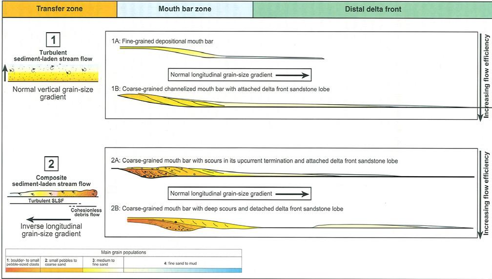
CHAPTER III TURBIDITE SYSTEMS: AN OUTCROP-BASED ANALYSIS 359
Fig. 402 A - Schemes showing depositional and bypass river mouth bars produced by turbulent flows (1) and composite dense flows (2). 1A shows a typical depositional mouth bar; 1B shows sigmoidal cross strata left behind by a plunging plume. 2A and 2B show coarsegrained bedload microdeltas produced by a bypassing flow. From Mutti et al. (2000).
Zavala et al. (2011) provide general and largely theoretical facies schemes for bedload and suspended load facies types in transfer and depositional zones of hyperpycnal flows that are essentially similar to those of Figure 403.
Facies and inferred processes of Figure 403 highlight the basic characteristics of bypass mouth bars, which are typically bounded by a basal erosional surface. For very powerful flows, this surface may be the only record of the bypass process and probably responsible for the origin of many “incised valleys” cut by fluvial processes in shallow marine environments seaward of channel exits (Figure 404). Where river outflows carry only suspended load and especially in settings without a marked shoreline break (e.g., bays, lagoons, ephemeral lakes), typical bypass facies are those with fluvial sigmoidal bedding described in previous sections. Most commonly, the fill of these channelized features results from the complex interplay between bypassing and depositional flows and is therefore characterized by similarly complex facies associations (Figure 404 A).
Depositional mouth bars form where flood-magnitude is substantially decreased and both bed load and most
part of the suspended load are deposited at or near river mouths. These bars have an excellent modern counterpart, though at much larger scale, of the classic river mouth bars of the Mississippi delta (Figure 405). Careful descriptions of these deposits by Coleman and Gagliano (1965) and Coleman and Wright (1975) (see also Elliott, 1986) clearly suggest that suspended load sedimentation during times of flood played a major role in depositing thin-bedded sand and mud in distal mouth bars and offshore regions with abundant climbing ripples and plant fragments. As suggested by Elliott (1986), sand transported by the river as bedload is deposited at the exit of distributary channels especially during floods, locally undergoing limited wave reworking, whilst the suspended load keeps moving seaward as buoyant river plumes (hypopycnal flows) or relatively dilute hyperpycnal flows. In the case of the Mississippi delta, fluvial floods can thus partly be followed from the transfer zones to the final depositional ones, suggesting that the process is responsible for at least a good proportion of the sedimentation. The fluvial-dominated deltas of Galloway (1975) should be actually redefined as flood-dominated deltas since “normal” floods are the only genuine fluvial process involved in the delta upbuilding.
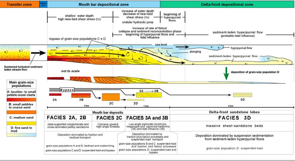
CHAPTER III TURBIDITE SYSTEMS: AN OUTCROP-BASED ANALYSIS 360
Fig. 403 - Basic facies and processes of bypass mouth bars as suggested by Tinterri (2007) in his study of the Eocene Roda Sandstone (Figols Group), south-central Pyrenees. The scheme refers to a flow with both bed load and suspended load and emphasizes the bypassing of the suspended load.
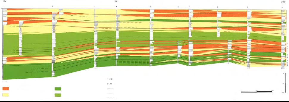
The basal erosional surfaces of these features are largely time-equivalent
the deposition of sandstone lobes farther seaward and essentially record bypass features (original data from Bongiorni, Cattellani, Cotti, Marchi, Sgavetti and Mutti, 1998-1999, unpublished; interpretation added). See Figure 440.
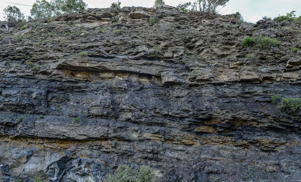
CHAPTER III TURBIDITE SYSTEMS: AN OUTCROP-BASED ANALYSIS 361
Fig. 404 - Examples of delta-front “incised-valley fills” (some are indicated by arrows) eroded by channelized hyperpycnal flows exiting distributary fluvial channels. These broadly channelized features have widths up to 1000-1500 m and depths up to 10-15 m. Their final infill is largely represented by channel-exit and channel-lobe transition facies and facies associations.
to
mouth-bars deposits and very proximal arenaceous lobes platform facies stratigraphic sections limits of recognized units “lower delta” unit highly concentrated levels of nummulites erosive surfaces proximal and distal arenaceous lobes external platform facies
Fig. 404 A - Multiple erosional surfaces (blue lines) produced by bypassing flows in a river mouth bar. Yellow arrow indicates a sandstone bed with sigmoidal cross bedding thought to be the product of a bypassing plunging plume. Note the fine-grained facies deposited between main flood events. Eocene Castigaleu Group, south-central Pyrenees.
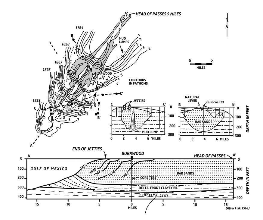
Mouth-bar deposits are the most sensitive to marine diffusion processes, being the shallowest element of deltaic depositional systems. As a consequence, they should be commonly reworked by tides and waves. The problem is dealt with in some detail in the following sections, though it may be anticipated that strong wave action is almost negligible in most cases and tidal action may become important particularly during transgressive periods when fluvial activity tends to get back normal conditions.
The correct recognition of river-exit mouth bars is fundamental for the identification of the shoreline – a key element to enter the sequence stratigraphic analysis of flood-dominated fluvio-deltaic system at the scale
of elementary depositonal sequences (see Chapter I). Mutti et al. (1996, 2000) (Figure 406) provided an early attempt to show the basic relationships between fluvial, bypass and depositional mouth-bar and lobe sedimentation along an ideal depositional profile.
Depositional mouth bars form under overall conditions of baselevel stillstand and are typical offlapping features produced by floods that deposit their bed load in bar crests (roughly the base level) and their suspended load as relatively thin sandstone beds that thin and shale out along the bar slope, or clinoforms (Figures 407). Typically, depositional mouth bars display thickening- and coarsening-upward facies sequences (Figures 407-408).
CHAPTER III TURBIDITE SYSTEMS: AN OUTCROP-BASED ANALYSIS 362
Fig. 405 - The classic Southwest mouth bar of the Mississippi delta showing its fast seaward progradation in historical times (1764-1959). Note the unusual thickness, produced by synsedimentary sinking in water-impregnated prodeltaic muds. From Gould (1970, originally from Fisk, 1961). The modern Mississippi cannot produce hyperpycnal flows that could transfer sand to more distal shelfal regions.
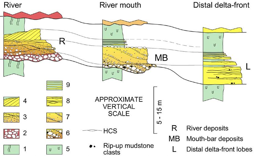
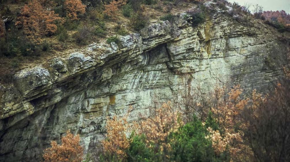
CHAPTER III TURBIDITE SYSTEMS: AN OUTCROP-BASED ANALYSIS 363
Fig. 406 - Tentative scheme to compare fluvial, river mouth, and distal delta front facies successions within the same elementary depositional sequence and for decreasing strength of flood-generated flows. The top of the mouth bar is roughly the base level at that time. From Mutti et al., 2000.
Fig. 407 - Typical depositional river mouth bar showing seaward dipping cross strata (clinoforms) emanating from a flat-lying bar crest recording baselevel. Note that the flat-lying bar crest is tilted to left by structural deformation. Packets bounded by clinoform surfaces show a marked shalying out in a seaward direction over very short distance. Eocene Atares delta, south-central Pyrenees.
Clinoform Marinefloodingsurface
Marine flooding surface
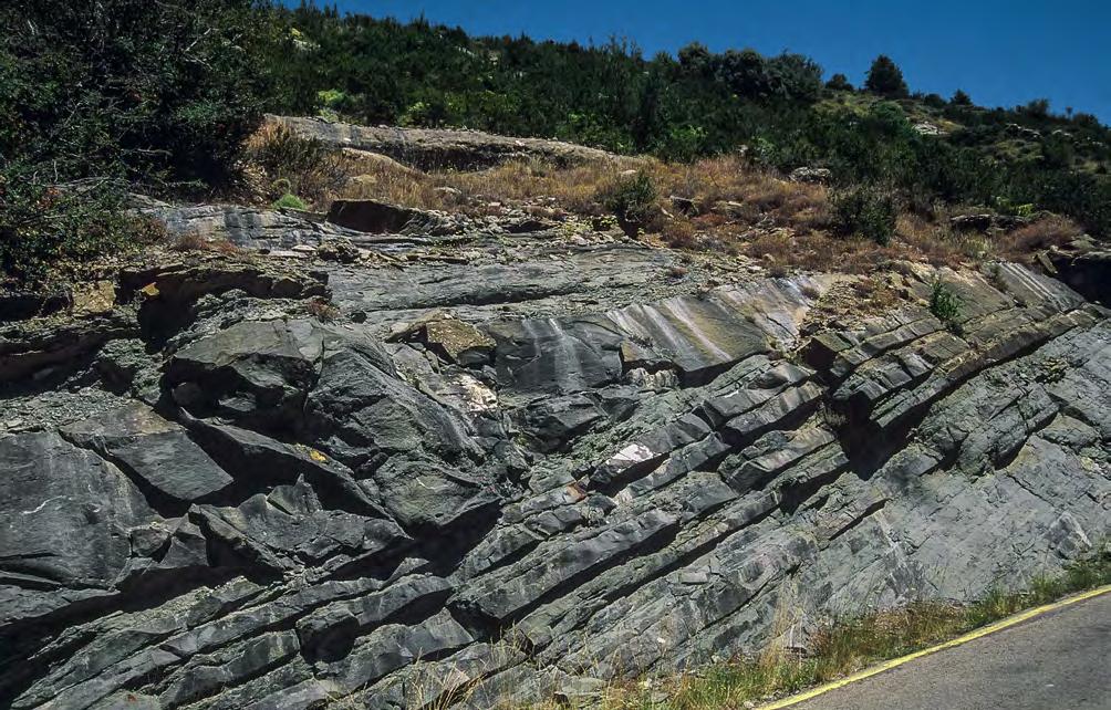
Thickening-upward Facies sequence
In small and coarse-grained systems, Gilbert-type mouth bars can develop in similar settings. The example of Figure 409 shows a coarse-grained mouth bar of a small river entering a lagoonal environment with locally well-developed toeset, foreset, and topset elements. The bar is part of a very complex depositional setting that well illustrates the difference between models and the real world (Figures 410) and highlights the importance of the context when examining an outcrop. Basically, the mouth bar progrades on top of an erosional surface cut by fluvial processes. The example of Figure 411) shows a Gilbert-type mouth bar of a bay-head delta sharply overlain by transgressive estuarine sandstone facies following a sea level rise. The basal contact of the estuarine sandstones is essentially a tidal ravinement surface.
As amply discussed in Chapter I with reference to elementary depositional sequences (EDSs) of some fluvio-deltaic deposits, depositional mouth bars typically form as a final prograding stage of sandy lithofacies recording relative lowstand of sea level and marking
the end of “small-scale” prograding lowstand wedges (see Stage II of Figure 412) that rest above sandstone lobes (Stage I, or highly efficient stage). Their top can be equated to a final regression surface or a marine transgressive surface indicating the beginning of baselevel rise. Needless to say, many mouth-bar deposits may form in settings where Stage I is absent because flood magnitude was not sufficient to produce hyperpycnal flows.
VII.3.3.2.2 – Channel-exit deposit of fan-delta systems
Virtually no information is available in the literature concerning facies changes between alluvial and marine conglomerates in fan-delta settings. A notable exception is that of Nemec and Steel (1984) who, on the basis of outcrop studies, first attempted to identify some criteria, especially useful to recognize facies produced by wave action (see also Nemec and Postma, 1993).
CHAPTER III TURBIDITE SYSTEMS: AN OUTCROP-BASED ANALYSIS 364
Fig. 408 - Depositional river-mouth bar showing seaward offlapping strata capped by an amalgamated bar crest in turn overlain by a transgressive surface. Note the well-developed thickening-upward facies trend from base to top. Eocene Arguis basin, south-central Pyrenees.
Lagoonal deposits
Topset (lag onglomerates)
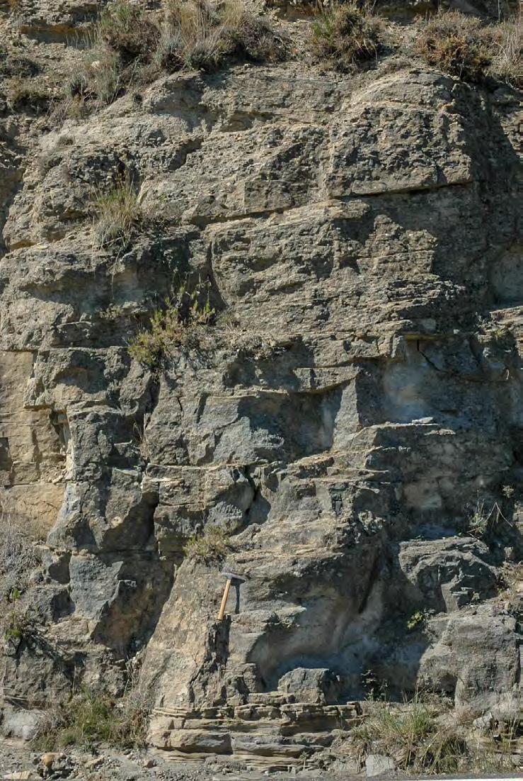
CHAPTER III
SYSTEMS: AN OUTCROP-BASED ANALYSIS 365
TURBIDITE
Fig. 409 - Vertical sequence of a coarse-grained Gillbert-type river mouth bar showing a well developd toeset, foreset and topset succession. The bar is overlain by a lagoonal transgressive surface. Eocene Figols Goup, south-central Pyrenees
Toesett
FORESET
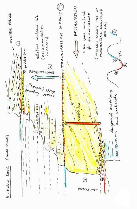
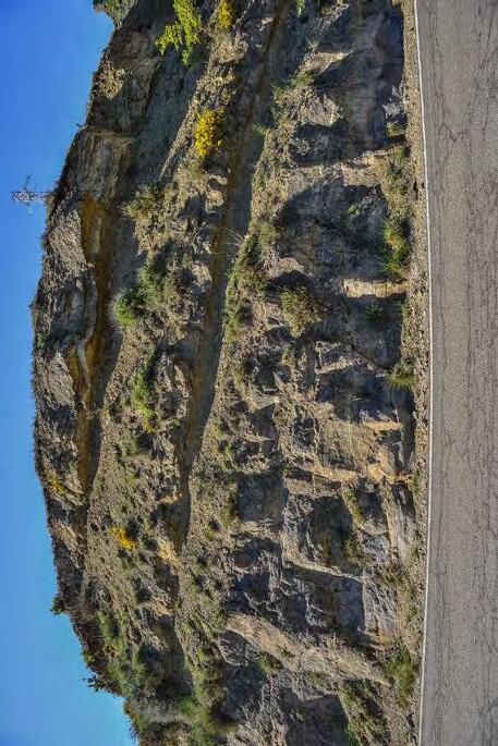
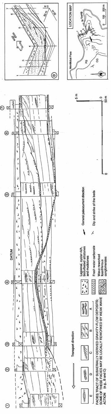
The same exposure of Figure 409 viewed within its context shows how a single outcrop rarely permits a satisfactory interpretation. A. Sketch prepared in the field for my students to explain the possible sequence-stratigraphic interpretation. The interpretation is probably correct, except for the upper sequence boundary that could be better interpreted as a transgressive ravinement surface produced by weak wave action on the shore of a lagoon; B. Detailed cross section showing the complex internal architecture of the sandstone body over a distance of some 200 m. The section clearly shows that the Gilbert-type mouth bar rests on an erosional surface probably cut by strongly hyperpycnal flows that deposited sandstone lobes farther seaward (from Mutti et al., 1994).
Fig. 410
CHAPTER III TURBIDITE SYSTEMS: AN OUTCROP-BASED ANALYSIS 366
A B
Lag conglomerates
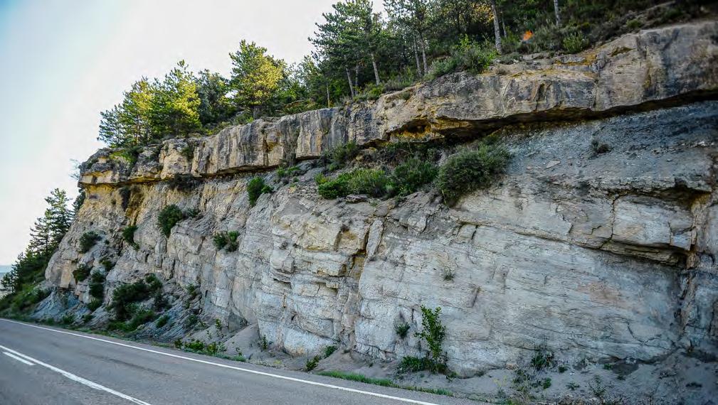
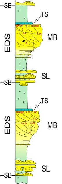
STAGE II
Sequence boundary Sequence stage
STAGE III (Aggradational-progradational) - Coarse sediment flux to the sea dramatically decreases and only mud can accumulate
TS: transgressive surface or, better, a fluvial retreat surface with no evidence for tidal or wave ravinement and clearly related to base level rise
STAGE II (Mainly progradational) - Poorly-efficient stage. Smaller-volume, flood-generated sediment-laden river outflows (as well as normal river outflows) are forced to deposit most of their sediment load at channel-exits (mouth bar).
STAGE I (Mainly aggradational) - Highly-efficient stage. Large-volume, flood-generated sediment –laden river outflows give way to hyperpycnal flows that can carry sand to shelfal regions and deposit tabular sandstone lobes. These lobes are in fact shallow-water turbidites.
CHAPTER III TURBIDITE SYSTEMS: AN OUTCROP-BASED ANALYSIS 367
Fig. 411 - Bay-head flood-dominated delta enclosed by lagoonal mudstones and overlain by estuarine sandstones. The delta is recorded by a Gilbert-type river mouth bar with seaward dipping cross strata truncated at their top by a topset of lag conglomerates. Following relative sea-level rise, the succession is overlain by transgressive estuarine sandstones where fluvial processes are mixed with strong tidal influence. Eocene Castissent Group, south-central Pyrenees.
Fig. 412 - Stages of growth of a fluvio-deltaic EDS.
Estuarine sandstones
Gilbert-type river mouth bar
As shown by outcrops of the Santa Liestra Group, south-central Pyrenees, some thick beds of structureless conglomerate, deposited by gravelly dense flows, become crudely cross-stratified in a downcurrent direction where they start to interfinger with fine-grained and fossiliferous marine strata (Figure 413) or directly pinch out in these sediments (Figure 414). This implies a similarly sudden loss of coherence of the flow quite probably as a result of deceleration and increased turbulence produced by the impact with seawater. The interpretation is supported by similar channel-exit settings of lacustrine fan-deltas of the Ebro basin. Here (Figure 415), tabular, graded and virtually matrix-free conglomerate
beds can be traced upcurrent over a distance of few meters into deeply scoured, structureless and very poorly sorted conglomerate beds, in turn overlain by downstream accreting conglomerate units, The interpretation suggested is that gravelly, unsorted and partly cohesive dense flows break when entering lake water and loose coherence passing into inertia-dominated frictional sheet flows virtually devoid of matrix and overlain by a supercritical sandy suspension (see Figures 414 and 415 of alluvial fan section). An example of a graded bed entirely composed of clast-supported conglomerate and overlain by a very thin sandstone division through a bypass surface is shown in Figure 416.
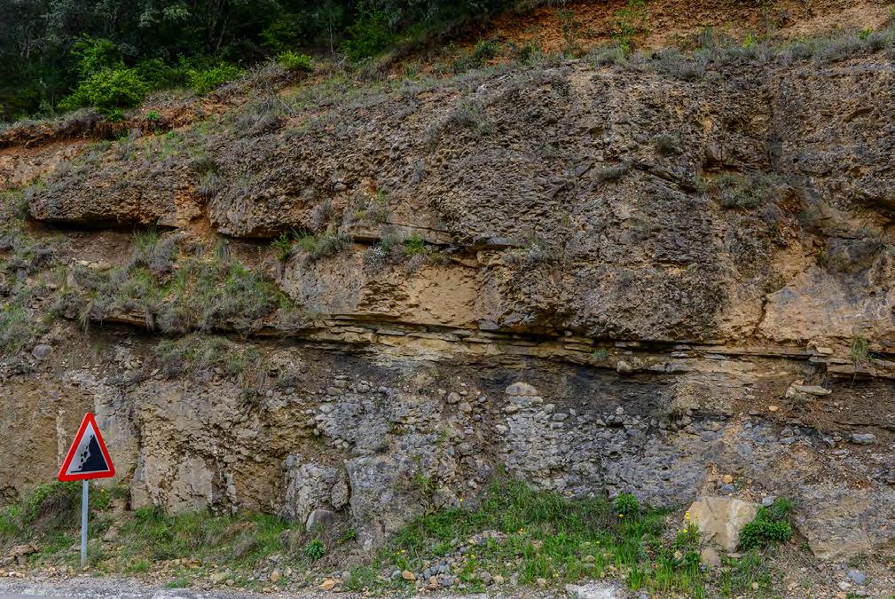
CHAPTER III
SYSTEMS: AN OUTCROP-BASED ANALYSIS 368
TURBIDITE
Fig. 413 - Crudely cross-stratified conglomerates interbedded with fine-grained, bioturbated and fossiliferous marine strata (red arrow). These cross-bedded conglomerates are thought to record a basic transformation of dense gravelly flows (see text). Eocene Santa Liestra Group, south-central Pyrenees.
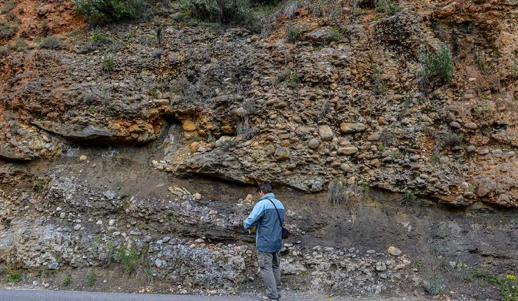
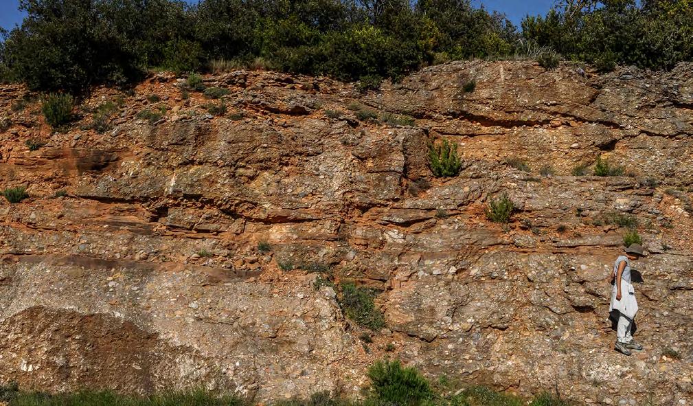
CBCGL
SCGL
TCGL
SCGL
CHAPTER III TURBIDITE SYSTEMS: AN OUTCROP-BASED ANALYSIS 369
Fig. 414-Downcurrent pinchout of crudely cross-stratified conglomerates and transition into bioturbated marine sandstones and mudstones (red arrows). Note the overlying thick beds of structureless conglomerates. Eocene Santa Liestra Group, south-central Pyrenees.
Fig. 415 - Graded tabular beds of clast-supported conglomerates (TCGL) passing upcurrent (left) into scoured, thicker bedded and poorly sorted conglomerates (SCGL). Lakeward dipping cross strata of poorly sorted conglomerates can be observed above and below. The exposure is here interpreted as a channel-exit zone of an alluvial fan entering a lake. Oligocene Ebro basin, south-central Pyrenees.
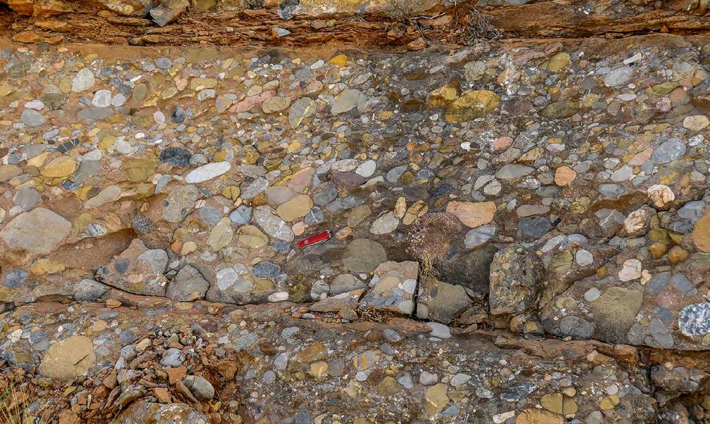
VIII.3.3.2.2.1 – Transient wave-action reworking
Some thick beds of structureless conglomerate may locally display one-pebble or one-cobble thick alignments on their upper surface, sharply draped by finegrained sediment (Figure 417). Similar, though rarer, features are expressed by pockets and lenses of relatively well-sorted and matrix-free pebble conglomerates that occur interbedded with structureless and typically poorly sorted gravelly flow deposit (Figure 418), Surfaces and deposits of this type can record phases of flow bypassing or some reworking by transient wave action immediately following deposition of the underlying structureless bed. This second interpretation is here preferred and thought to be related to local and transient wave action produced by seawater set in mo-
tion by thick dense flows entering a very shallow marine environment. The interpretation is substantiated by the total lack of associated beach deposits within the section, thus pointing out the occurrence of an unexpected process in an otherwise low-energy environment episodically subject to floods. Some pebbles and cobbles of these alignments display encrusted oysters and traces of boring organisms, suggesting that for a while these clasts remained in very shallow water. To what extent these transient waves may be related to the origin of HCS remains an open problem, certainly worth future research. My personal opinion is that this much overlooked strong transient wave activity is one of the causes of HCS in flood dominated deposits, in both seawaters and lakes.
CHAPTER III TURBIDITE SYSTEMS: AN OUTCROP-BASED ANALYSIS 370
Fig. 416 - Internal structure of a tabular conglomeratic bed of Figure 415. The basal conglomerate division consists of two graded units (dashed yellow line) and is almost matrix free. The yellow arrow indicates the bypass surface separating the conglomerate division from an overlying thin sandstone division.
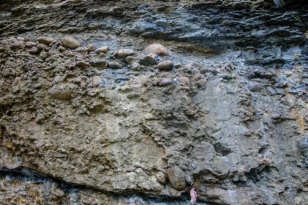
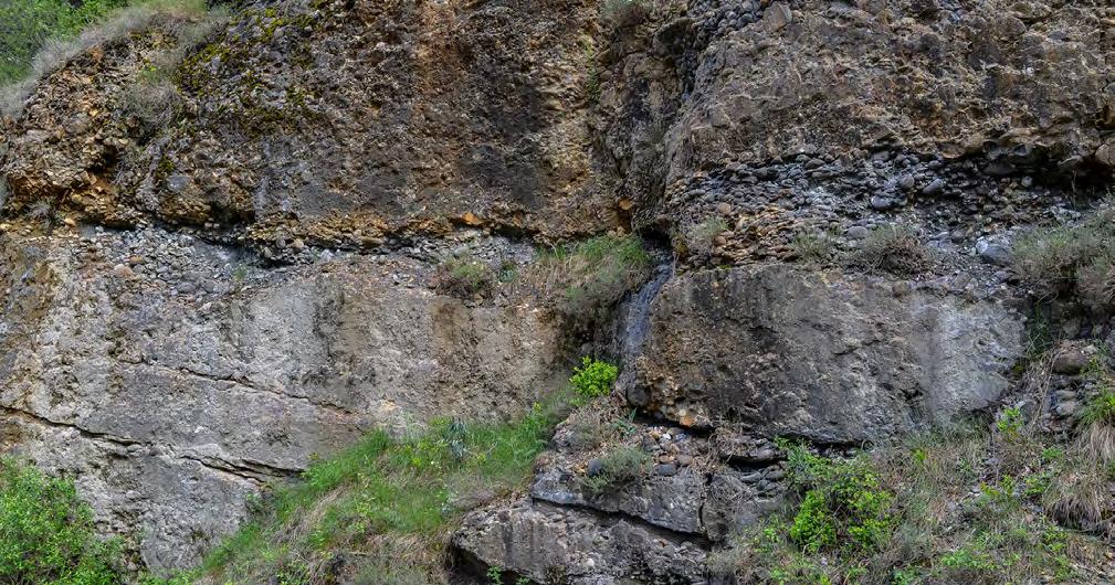
Transient wave-action reworking
CHAPTER III TURBIDITE SYSTEMS: AN OUTCROP-BASED ANALYSIS 371
Fig. 417 - Example of transient wave-action reworking (yellow arrows) at the top of a thick bed of structureless conglomerate. Note that the cobble and pebble alignment is directly overlain by fine-grained, bioturbated and fossiliferous marine facies. Eocene Santa Liestra Group, south-central Pyrenees.
Fig. 418 - Pockets and convex-upward lenses of relatively well-sorted pebble conglomerate probably recording strong, transient wave action produced by the catastrophic onset of a thick dense flow in very shallow water. Eocene Santa Liestra Group, south-central Pyrenees.
VIII.3.3.3 – The sandstone lobe element
Shelfal sandstone lobes are very common in the fill of ancient tectonically active basins where they may give way to impressive accumulations of graded, parallel-sided beds of sandstones and pebbly sandstones in nearshore and shelfal zones. This element is certainly the most impressive evidence of flood-dominated processes in the marine environment. From an economic standpoint, the sandy accumulations that may occur in this element constitute an overlooked target of oil exploration
Goldring and Bridge (1973) first perceived the stratigraphic importance of these nearshore and shelfal sediments in the ancient record, termed them “sublittoral sheet sandstones”, and proposed various origins including storms, tsunamis, floods, tides, rips and turbidity currents. Though Martinsen (1990) had first interpreted elongate delta-front sandstone bodies, or lobes, from the Namurian of northern England as the product of flood-generated hyperpycnal flows, these sediments have long been mistaken for storm-dominated nearshore and shelfal deposits because of the common occurrence of HCS, a structure generally considered as diagnostic of combined-flow conditions associated with storm activity along high-energy coasts (e.g., Duke, 1985).
As noted by Mutti et al. (1996, 2000) and later emphasized by Tinterri (2007, 2011), combined flow conditions are not unique of storm-dominated settings and are even common in deep-water turbidite sedimentation. Whatever its formative process, the abundance of HCS in sandstone lobes of both flood-dominated river-delta and fan-delta systems cannot be related to storm processes along high-energy coasts for the simple reason that such settings, and their resulting high-energy beach deposits, do not occur in all the examined basins. Conversely, sandstone lobes grade landward into alluvial fans or river mouth bars without intervening beaches. The paradigm that HCS can only mean storm-dominated shelves has thus to be considered with caution and in a new perspective. Transient wave reworking (see above) may partly explain this feature which is common in both shallow lakes and seas.
Shelfal sandstone lobes were first recognized, described and interpreted as a deposit of flood-generated hyperpycnal flows by Mutti et al. (1996, 2000) and related by these authors to delta-front deposition in both flood-dominated fan-delta and river-delta systems. These lobes were described as m-thick, tabular features made up of graded sandstone beds locally
with locally abundant skeletal debris and mudstone clasts and typically displaying HCS produced by combined-flow conditions. Examples of these tabular units from different basins are shown in Figures 419-420.
Sandstone lobes form wherever sufficiently wide and low-gradient shelves, developed in front of distributary fluvial channels or alluvial fans, provide a deceleration zone for hyperpycnal flows during flood times. In settings with narrow or no shelves, these flows would move directly to deeper water as turbidity currents. As hyperpycnal flows are density currents suffering the “bottom-seeking” effect, the loci of deposition of these flows may be affected by local topography. Thickness and lateral extent of individual lobes and lobe packages are primarily controlled by the sediment flux of the feeder fluvial channels, i.e., by the characteristics of the local fluvial system and the type of sediment supplied by its drainage basin.
Shelfal sandstone lobes occur may as thick accumulations of amalgamated and relatively fine-grained sandstone beds deposited by collapsed plunging plumes (Figure 421), similarly thick conglomerate successions deposited by dense flows in proximal fan-delta settings (Figure 422) or, more commonly, as m-thick sandstone packets with tabular geometry (Figure 420) cyclically alternating with muddier and usually bioturbated facies.
Facies types range from disorganized conglomerates deposited by dense gravelly flows to fine-grained and thin-bedded sandstpne deposited by relatively dilute turbulent flows. Transitional facies include graded pebbly sandstones, ungraded or crudely graded coarse-grained sandstone beds with mudstone clasts, and medium- to fine sandstone beds with HCS.
Mutti (1992b) and Mutti et al. (1996, 2000, 2007) provided preliminary schemes to describe facies tracts and inferred processes for both fan-delta (Figures 423 and 424) and river delta (Figure 425) sandstone lobes, emphasizing the ability of hyperpycnal flows to increase their density through bed erosion, resulting in abundant mudstone clasts and skeletal debris, as well as the common occurrence of HCS in these deposits. Subsequent work (see Slatt and Zavala, eds., 2011, with references therein, and Zavala and Pan, 2018) has mainly emphasized the complexity of the processes governing hyperpycnal flows and their deposits and attempted to provide more detailed, though essentially similar, facies models. Since most of the processes still remain poorly understood, in the following we will rather emphasize facies characteristics.
CHAPTER III TURBIDITE SYSTEMS: AN OUTCROP-BASED ANALYSIS 372
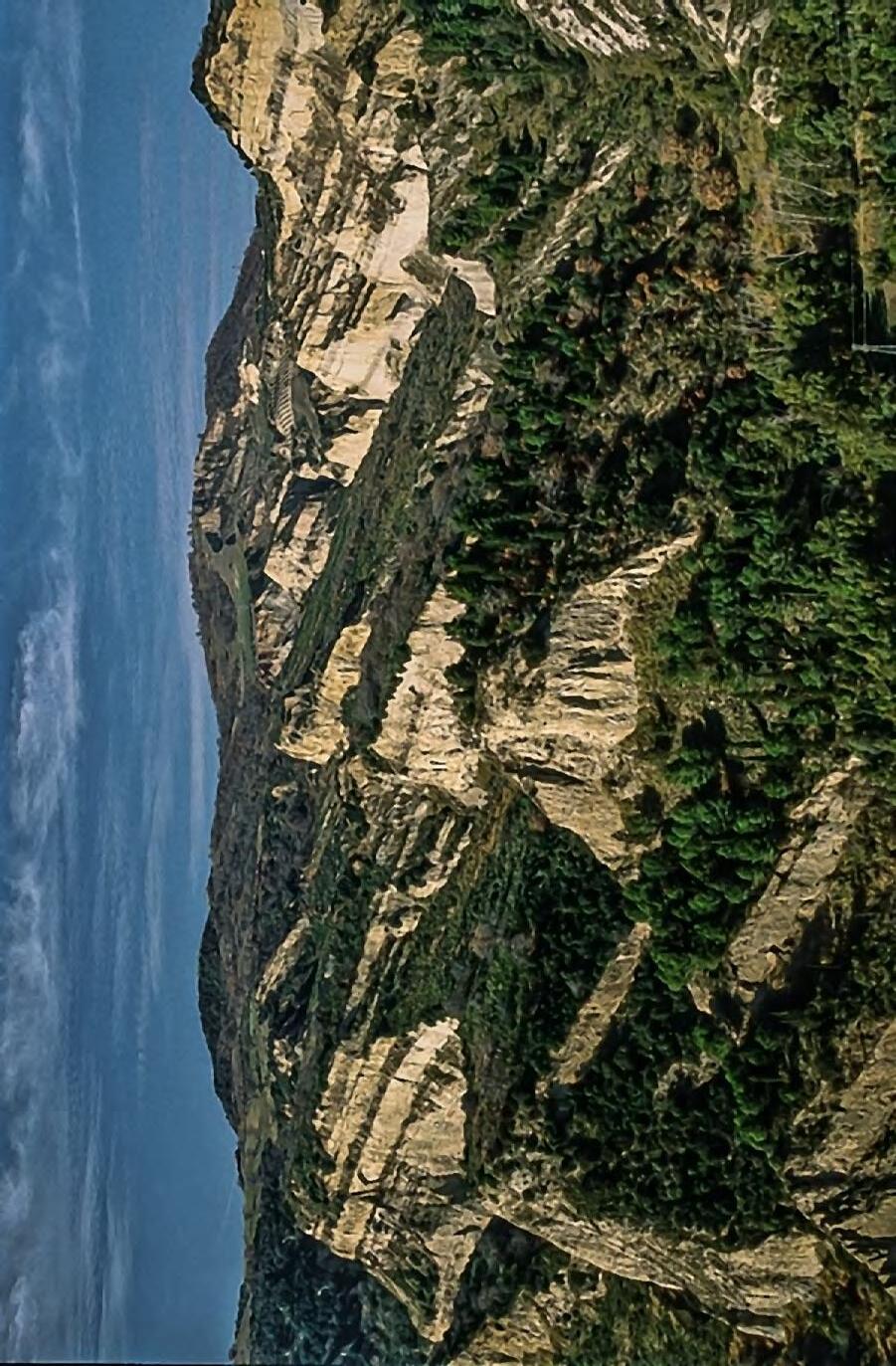
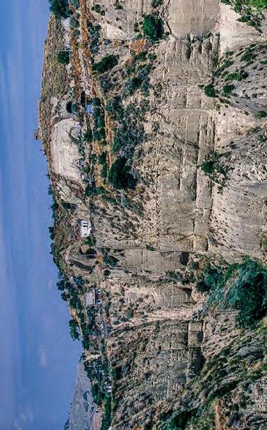
A. Packages of thick-bedded sandstone lobes separated by muddier units. Note the tabular geometry of each package.
Fig. 419
Sant’Arcangelo basin, Basilicata, southern Italy
Pliocene-Pleistocene
B. Close-up of a lobe element showing amalgamated, thick to very thick sandstone beds. These beds, which are mostly fine-grained, are thought to be the deposit of collapsed plunging plumes with very high rates of sedimentation. Most beds are structureless or display faint lamination, including large-scale HCS. Water-escape features are very common.
CHAPTER III
SYSTEMS: AN OUTCROP-BASED ANALYSIS 373
TURBIDITE
A B
Sandstone lobes
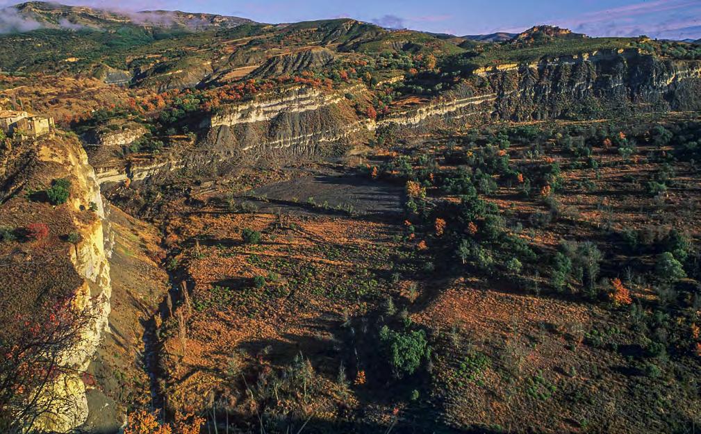
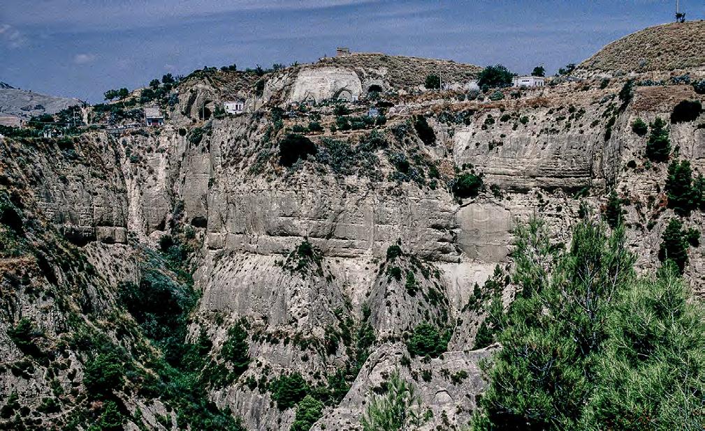
CHAPTER III TURBIDITE SYSTEMS: AN OUTCROP-BASED ANALYSIS 374
Fig. 420 - Tabular sandstone lobes alternating with prodeltaic mudstones. Eocene Figols Group, south-central Pyrenees.
Fig. 421 - Thick accumulations of fine- to medium-grained sandstone lobes in amalgamated tabular beds thought to be the deposit of collapsed plunging plumes. Pliocene-Pleistocene Sant’ Arcangelo basin, southern Italy.
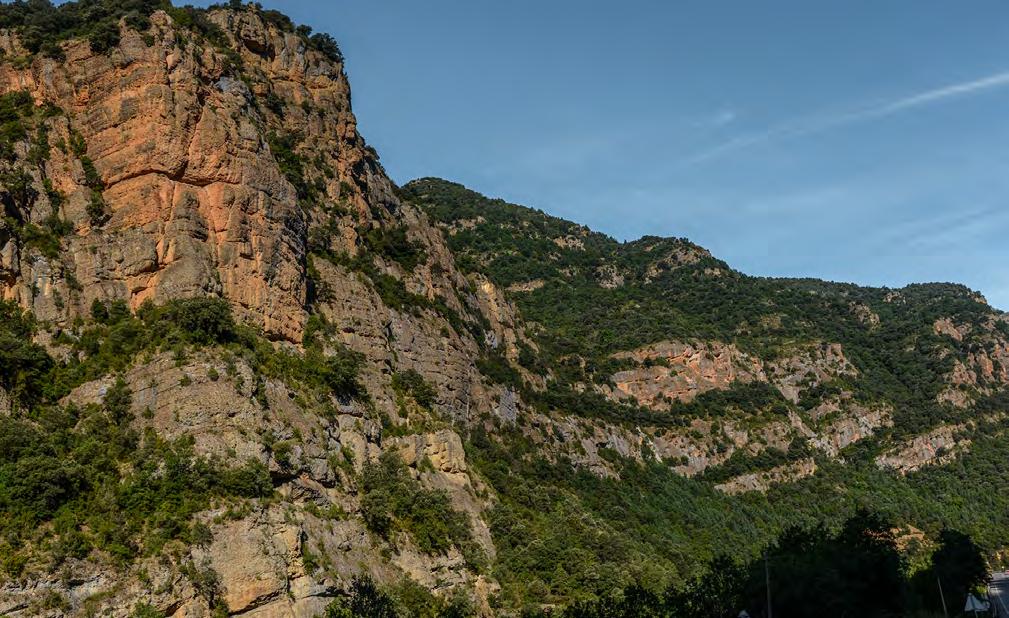
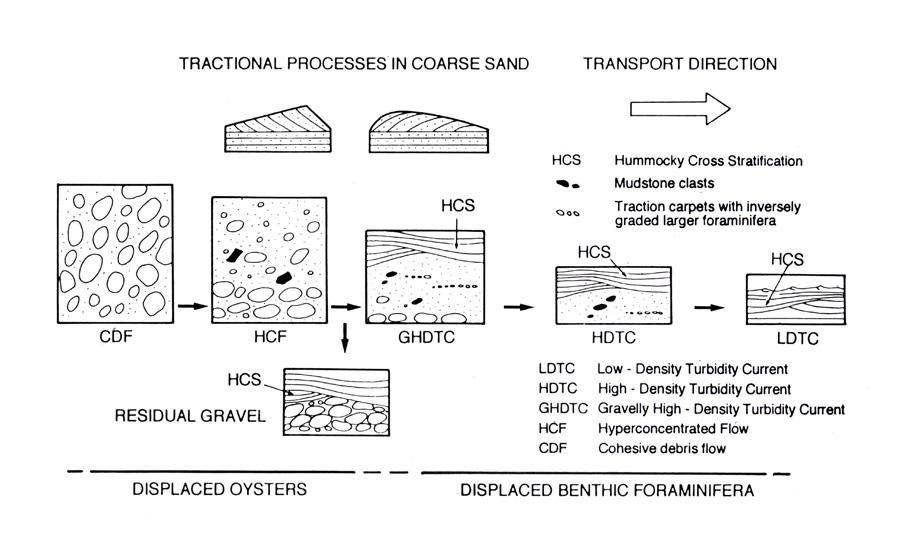
CHAPTER III TURBIDITE SYSTEMS: AN OUTCROP-BASED ANALYSIS 375
Fig. 422 - An impressive succession of conglomerates deposited by gravelly dense flows in the proximal marine environment of a fan delta system. Individual flood units form thick packets of amalgamated conglomerates separated by thin finer-grained marine intercalations. Eocene Santa Liestra Group, south-central Pyrenees.
Fig. 423 - A highly preliminary facies tract of a flood-dominated fan delta system as suggested by Mutti (1992 b) with transition from debris flow to low-density turbidity current deposits in a down current direction. Note the emphasis on HCS.
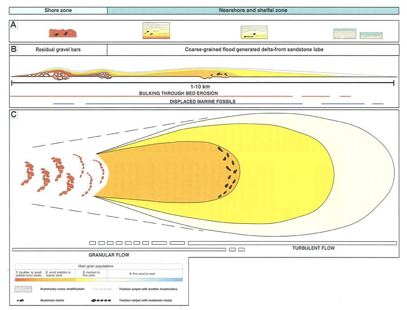
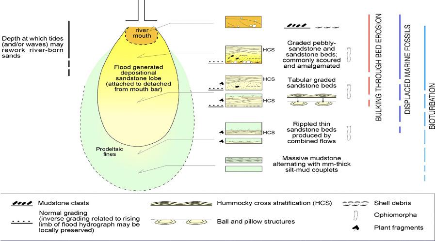
CHAPTER III TURBIDITE SYSTEMS: AN OUTCROP-BASED ANALYSIS 376
Fig. 424 - Tentative facies tract of flood-dominated fan delta as suggested by Mutti et al. (2000)
Fig. 425 - Depositional model of flood-dominated river deltas as suggested by Mutti et al. (2007). Note that some bed load is involved, either carried by river ouflows or washed out from former mouth bar deposits.
The facies tract of fan-delta and river-delta sandstone lobes are shown in Figure 426, following the simpler scheme of dense and more dilute turbulent flows. It will be noted that the two tracts become identical where the flow is in both cases subcritical, and deposition takes place through traction-plus-fallout from a relatively dilute turbulent suspension. It is in this kind of deposition that HCS develops, probably because the oscillatory component of the flow has had no effect on the preceding inertia-dominated dense flow.
The fan-delta facies tract is mainly based on the spectacular exposures of the Eocene Santa Liestra Group, south-central Pyrenees (Figure 427), and the Oligocene-Miocene Capo di Orlando Formation in southern Italy. The river delta facies tract is derived from several examples and particularly from the Eocene Sabinanigo Sandstone (see later) and the Figols Group in the south-central Pyrenees.
The lobe elements of fan-delta systems are easy recognizable in the field due to the sudden appearance of conglomerates and graded pebbly sandstones within muddier nearshore and shelfal marine successions, i.e., where normal marine processes, such as waves and tides, cannot rework gravel-size particles. These coarse-grained deposits are the typical product of dense gravelly flows emanating from adjacent alluvial fans (or similar coarse-grained systems).
In a seaward direction, the following main facies can be recognized:
Proximal Conglomerates
Poorly sorted, cobble to pebble conglomerates supported by limited amounts of sandy matrix with granules and small pebbles, in thick to very thick beds which can be either amalgamated or separated by thin and discontinuous finer-grained and locally fossiliferous and bioturbated facies. This kind of facies appears as the most proximal marine deposit of lobe elements and can be expressed by stratigraphic thicknesses up to hundreds of meters. Pebbles and cobbles are relatively well-rounded, suggesting prolonged fluvial transport before sedimentation. Beds are commonly structureless (Figures 428 and 429) or, in places, may display crudely developed cross laminae where the conglomeratic units pinch-out in a seaward direction (Figure 430). Beds can display crude normal grading, as well as inverse grading or, in most cases, a basically ungraded structure. In the Santa Liestra Group, some beds show evidence of wave reworking at their top expressed by the development of pebble or cobble alignments. In other cases, however, the same alignments are clearly the product of reworking by bypassing flows (see above). The suggested interpretation of these conglomerates is that of dense gravelly flows that suffered frictional freezing entering seawater and were bypassed by trailing sandy dense flows.
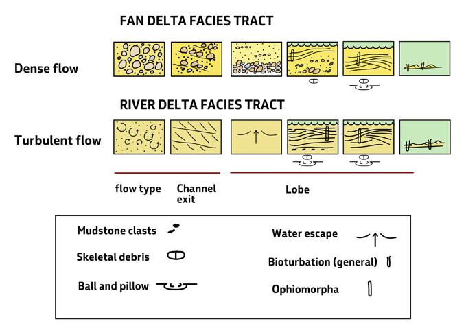
CHAPTER III TURBIDITE SYSTEMS: AN OUTCROP-BASED ANALYSIS 377
Fig. 426 - Basic facies tracts of fan delta and river delta systems.
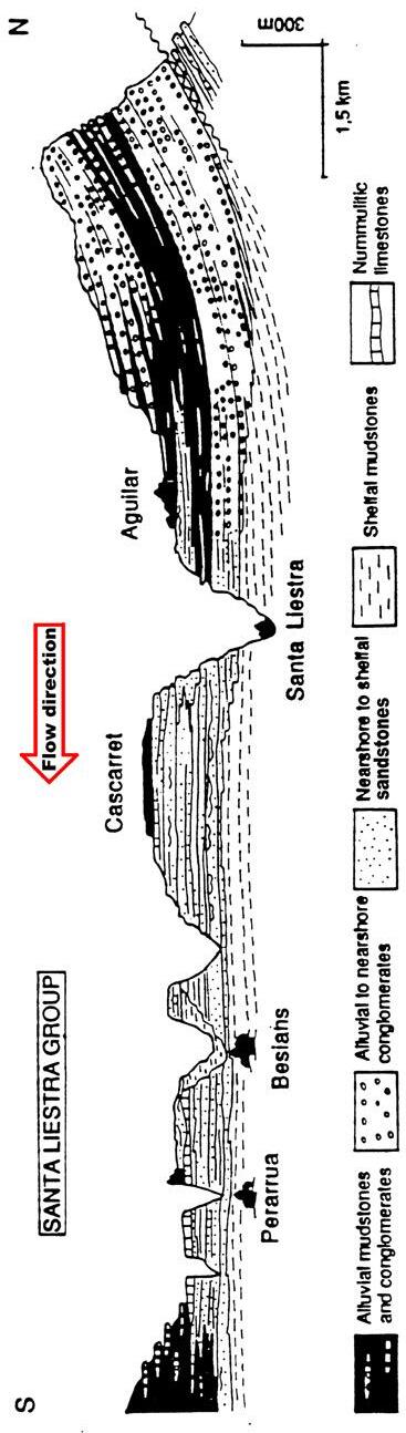
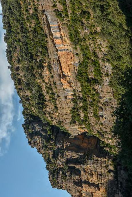
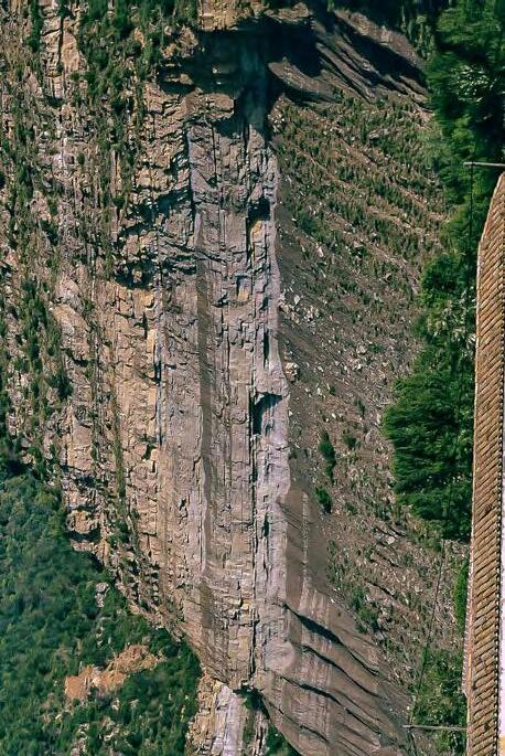
CHAPTER III TURBIDITE SYSTEMS: AN OUTCROP-BASED ANALYSIS 378
Fig.
427
The spectacular facies change over short distance from conglomerates to sandstones in the flood-dominated fandelta front of the Eocene Santa Liestra Group, south-central
Pyrenees. Cross-section from Crumeyrolle and Mutti, 1984.
Sandstone lobe
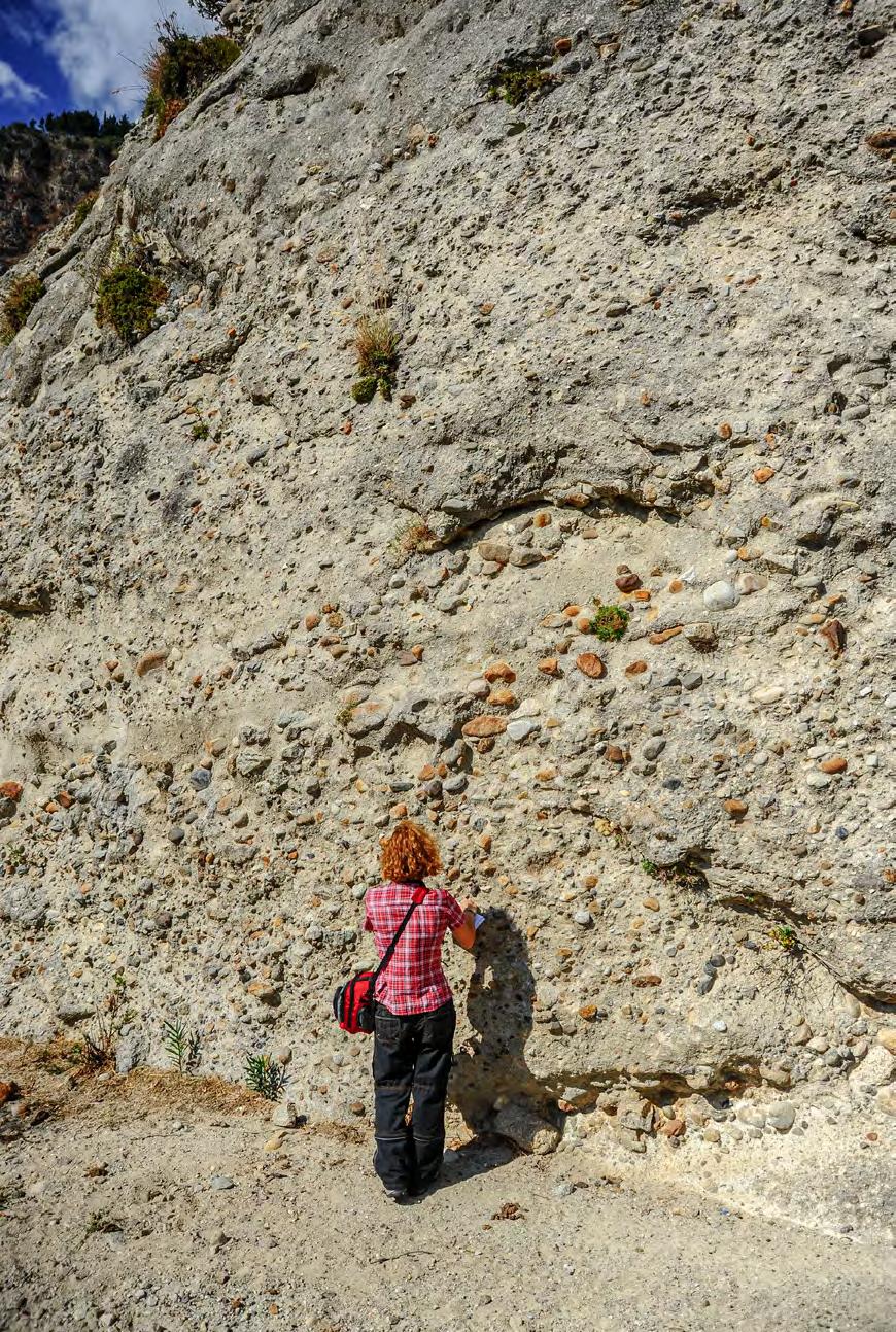
CHAPTER III TURBIDITE SYSTEMS: AN OUTCROP-BASED ANALYSIS 379
Fig. 428 - Amalgamated flood units consisting of structureless beds of conglomerates with abundant sandy matrix overlain by coarse-grained sandstone divisions. Proximal fan-delta lobe element. Oligocene-Miocene Stilo-Capo d’ Orlando Formation, southern Italy.
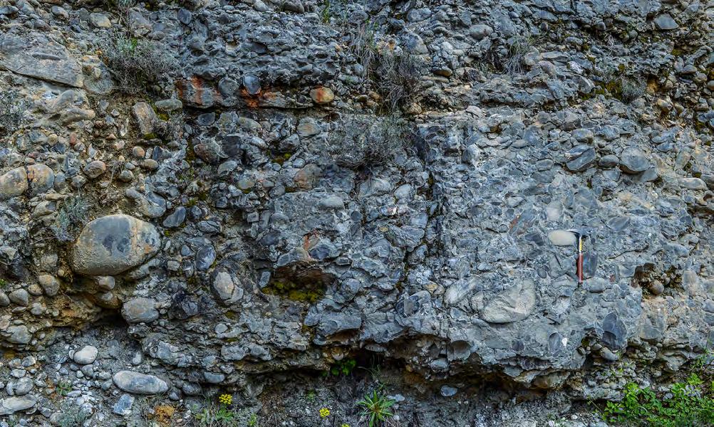
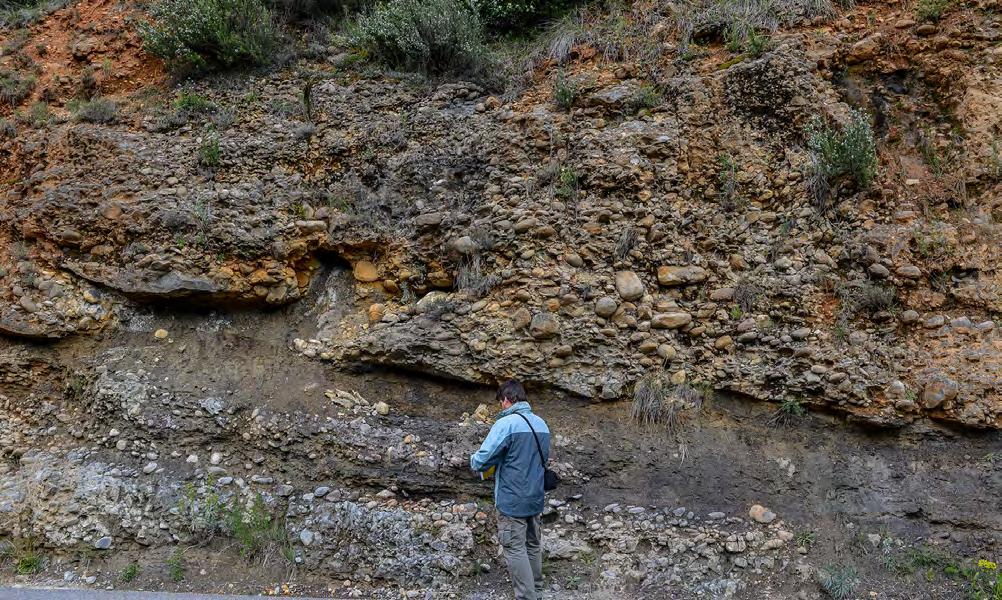
CHAPTER III TURBIDITE SYSTEMS: AN OUTCROP-BASED ANALYSIS 380
Fig. 429 - Typical example of gravelly dense flow deposit consisting of an ungraded and structureless conglomerate. Eocene Santa Liestra Group, south-central Pyrenees.
Fig. 430 - Downcurrent pinchout (yellow arrow) of crudely cross-stratified conglomerates and transition into bioturbated marine sandstones and mudstones. Note the overlying thick beds of structureless conglomerates. Eocene Santa Liestra Group, south-central Pyrenees.
Intermediate conglomerate/sandstone couplets (graded pebbly sandstones)
These sediments form immediately downcurrent of the proximal conglomerates, representing the transition to the more distal sandstone facies of the lobe element. They consist of beds, or flood units, where a basal conglomeratic division is overlain by a sandstone division. These basal divisions can be thick, structureless, ungraded or crudely graded (Figure 431), or thinner (in some cases one-pebble thick), broadly convex-upward lenses (Figures 432-434). In both cases these divisions grade into the overlying sandstone through thick, poorly to well defined laminae containing progressively smaller pebbles In some instances, relatively thin basal conglomeratic divisions may form isolated lenses resembling pebble clusters. The thick divisions record deposition from dense gravelly flows that had sufficient momentum
to partly bypass the channel exit and the proximal lobe zones; the thinner and lenticular divisions are gravel carpets that moved farther seaward sheared by an overlying flow. Settings of this kind have been previously discussed in terms of processes (this chapter IIIA, Figure 314) and observed, with similar characteristics, in alluvial fan depositional systems.
Distal sandstone/mudstone couplets (sandstones with HCS)
This facies is the most common and consists of graded sandstone/mudstone couplets forming tabular graded beds and cyclically stacked m-thick bedsets separated by finer-grained facies (Figure 435, see also Figure 427). Each bedset can be defined as a typical sandstone lobe. A spectacular example of cyclically stacked sandstone lobes is shown in Figure 436.
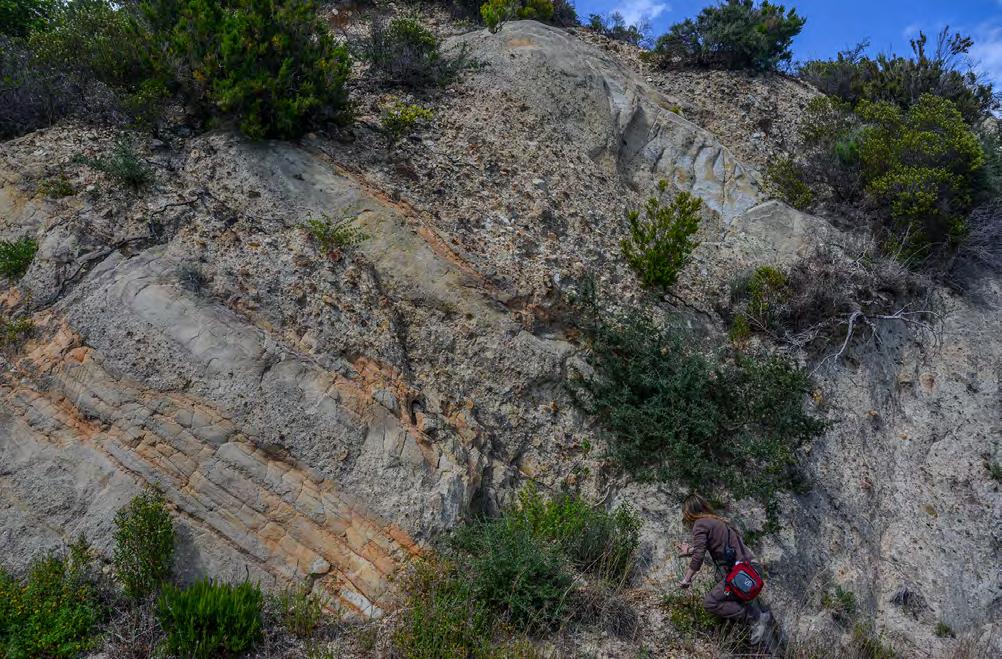
CHAPTER III
SYSTEMS: AN OUTCROP-BASED ANALYSIS 381
TURBIDITE
Fig. 431 - Thick to very thick conglomerate/sandstone couplets (yellow arrows) overlying thinner couplets with lenticular geometry of the conglomerate divisions (red arrow). Oligocene-Miocene Stilo-Capo d’ Orlando Formation, southern Italy.
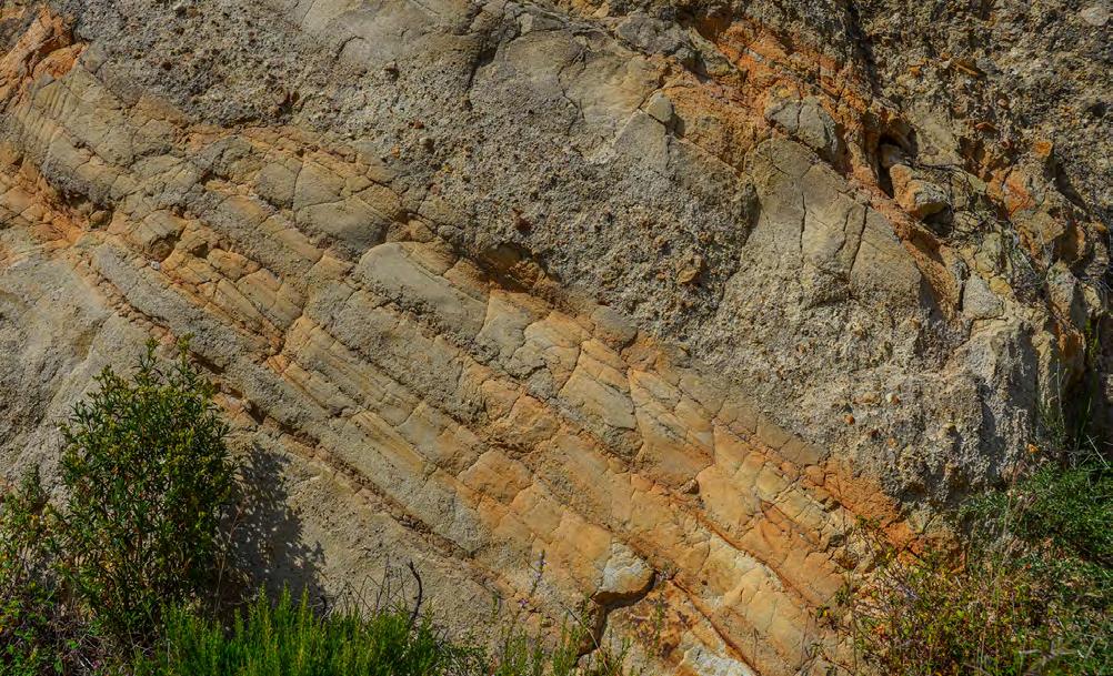
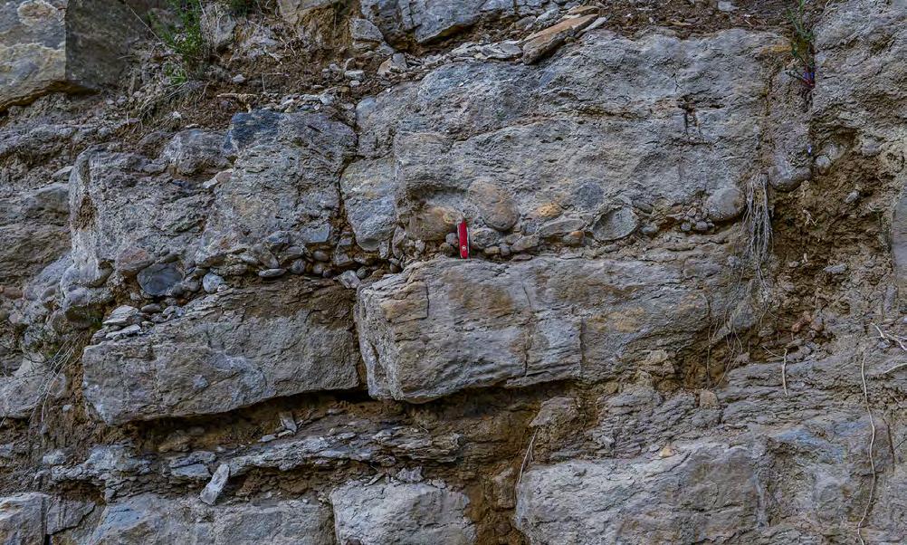
CHAPTER III TURBIDITE SYSTEMS: AN OUTCROP-BASED ANALYSIS 382
Fig. 432 - Conglomerate/sandstone couplets in a fan-delta front. In thicker beds, conglomerates show basal scours (red arrow); in thinner beds, conglomerates form thin and discontinuous divisions with a broadly convex-upward geometry (yellow arrow). Oligocene-Miocene Stilo-Capo d’Orlando Formation, Calabria, Italy.
Fig. 433 - Conglomerate/sandstone couplet. Note pebble “cluster” in the conglomerate division (arrow) overlain by a coarse-grained sandstone division with small and abundant mudstone clasts. Eocene Santa Liestra Group, south-central Pyrenees.
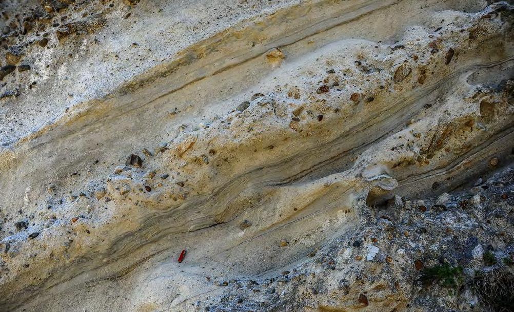
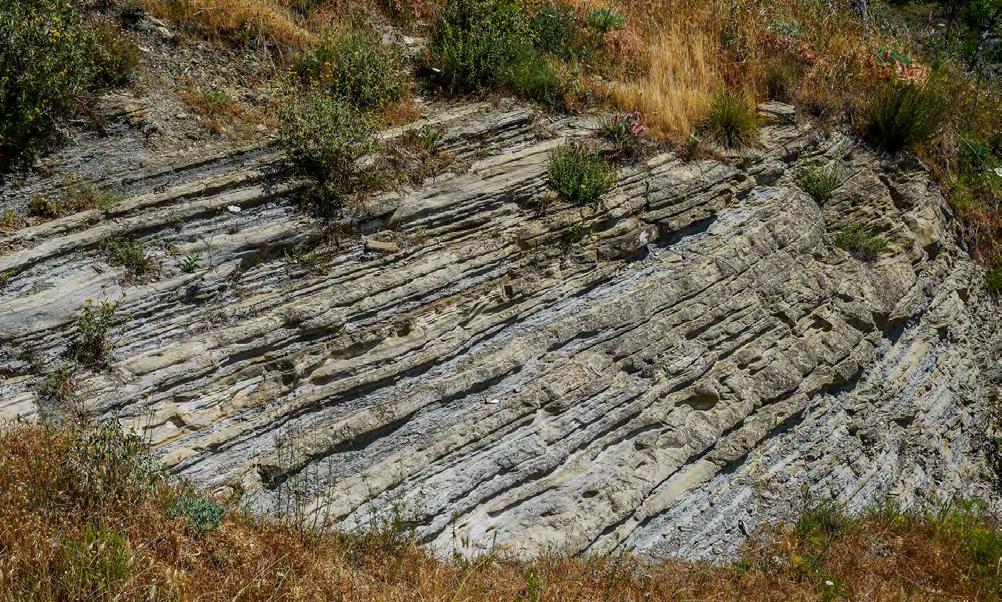
CHAPTER III TURBIDITE SYSTEMS: AN OUTCROP-BASED ANALYSIS 383
Fig. 434 - Conglomerate/sandstone couplets. Graded pebbly sandstones without intervening mudstone partings. Note abrupt pinch-out of conglomerate division of Bed 2 and inverse grading in the basal division of Bed 3. Oligocene-Miocene Stilo-Capo d’Orlando Fm, Calabria, Italy.
1 2 3
Fig. 435 - Typical exposure of a shelfal sandstone lobe consisting of sandstone/mudstone couplets of variable thickness. Oligocene-Miocene Silo-Capo d’ Orlando Formation, southern Italy.
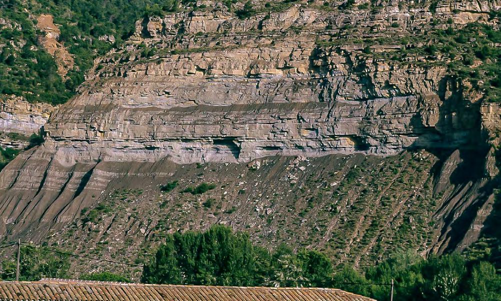
The characteristics of the sandstone divisions of each couplet vary in a downcurrent direction. In proximal sectors, at the transition with the conglomerate/ sandstone couplets, the sandstone division contains a basal portion of structureless or crudely laminated coarse-grained sandstone with mudstone clasts that is truncated by high-amplitude HCS (Figure 437). Moving downcurrent, this coarse-grained division is replaced by finer-grained sandstone with HCS of progressively lower amplitude (Figure 438). In both cases, HCS grades upward into a division of current ripples commonly with an oscillatory component, in turn capped by a mudstone division. In most cases, the current ripple division and the overlying mudstone are strongly affected by bioturbation.
The HCS divisions are herein interpreted as the deposit of a traction-plus-fallout process taking place from the suspended load of a turbulent flow with a progressively decreasing oscillatory component.
In river delta systems, sandstone lobes tend to be fine-grained (most commonly fine sand) because they are the product of plunging plumes of suspended load exiting river mouths. If fed by relatively large drainage basins with large amounts of suspended load, these plumes can develop sustained flows that result in impressive tabular sandstone bodies (Figure 439) extending across the shelf over several km and carrying large volumes of fines in outer shelf and slope regions (see later). Figure 440 shows an example of this kind of sedimentation from the Eocene Sabinanigo Sandstone, south-central Pyrenees, where these bodies (pale yellow), emanating from river mouths (orange) and passing seaward into bioturbated prdeltaic mudstones, can be followed for at least 10 kilometres in a section roughly perpendicular to paleocurrent direction. The local succession is part of a prograding lowstand to early transgressive delta complex capped by a maximum flooding surface.
CHAPTER III TURBIDITE SYSTEMS: AN OUTCROP-BASED ANALYSIS 384
Fig. 436 - Cyclic stacking pattern of shelfal sandstone lobes. Note the overall tabularity. Eocene Santa Liestra Group, south-central Pyrenees.
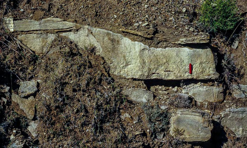
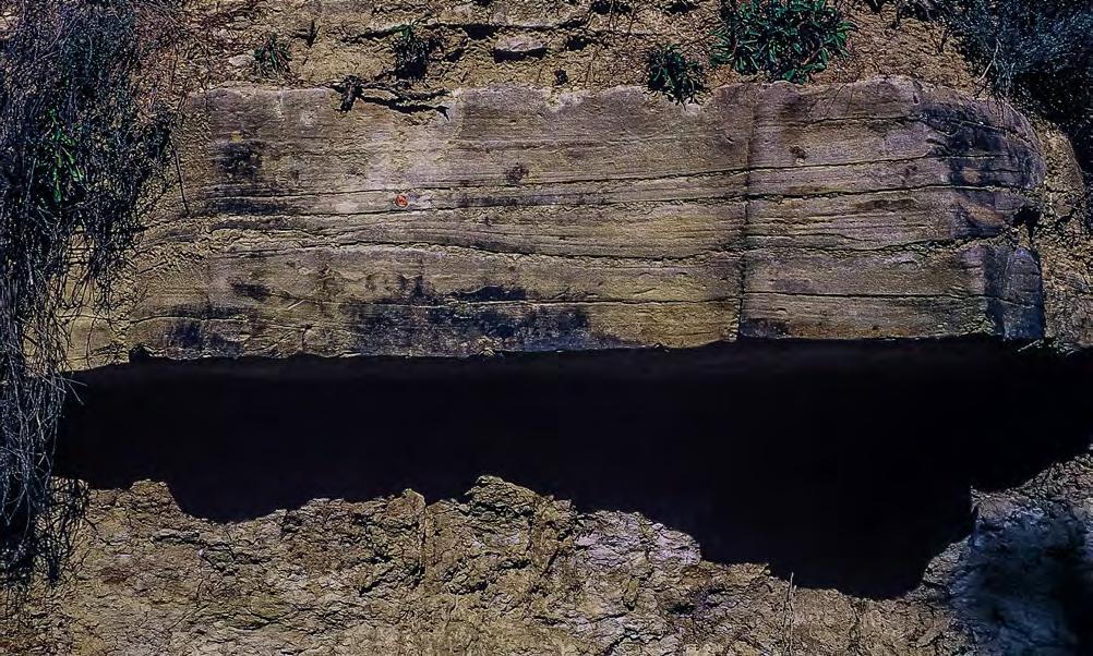
CHAPTER III TURBIDITE SYSTEMS: AN OUTCROP-BASED ANALYSIS 385
Fig. 437 - Graded structureless sandstone division, with mudstone clasts and skeletal debris, truncated by HCS. Eocene Santa Liestra Group, south-central Pyrenees.
Fig. 438 - Sandstone/mudstone couplet. Sharp-based sandstone division with hummocky cross stratification. Eocene Santa Liestra Group, south-central Pyrenees.
HCS
Shelfal tabular sandstone lobes
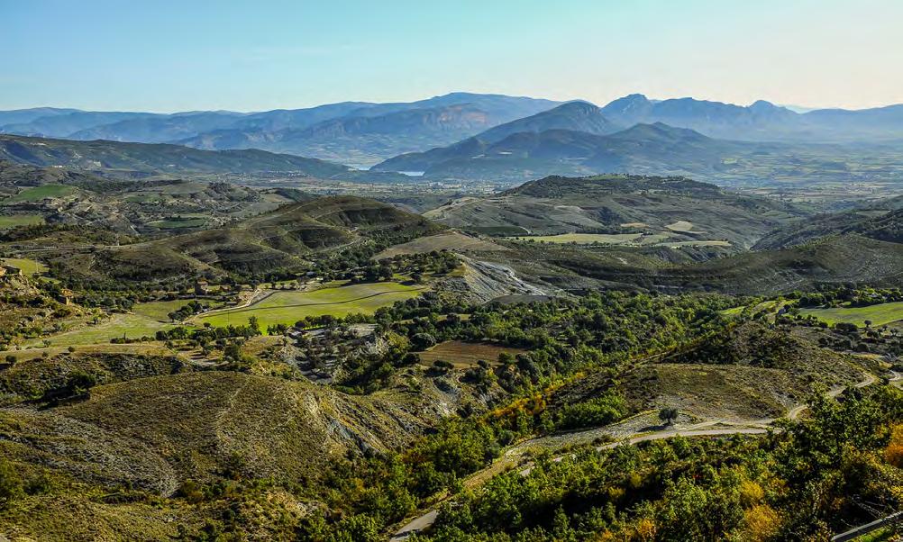
More generally, sandstone lobes typically develop as m-thick sandstone bodies alternating with finer-grained and commonly bioturbated facies of variable thickness. The sandstone bodies, each being an individual lobe, are made up of sandstone beds separated by mudstones and may display highly variable sand/ mudstone ratios depending on the type of system under consideration and the position along the original depositional profile. The beds consist of sharp-based, parallel-sided, fine- to medium-grained sandstone/ mudstone couplets commonly with individual thickness up to 1–1.5 m; where fully developed, the sandy portion of these beds includes a basal division of parallel or hummocky cross laminae (Figure 441) followed upward by a division of current ripples, commonly displaying a
strong oscillatory component (Figure 442); the ripple division is transitionally capped by a mudstone division. Most commonly, the upper portions of these beds are highly bioturbated and in some cases bioturbation may affect the entire lobe thickness (Figure 443).
The interpretation offered for these beds is the same as that offered for the similar facies observed in fan-delta systems (see above), i.e., a type of deposition taking place from fallout from a waning overlying suspension. The relatively fine-grained texture (mostly fine and very fine sand), the lateral continuity of individual beds and bedsets, and the clear stratigraphic relationhips to river mouth bar strongly suggest an origin from sustained plunging plumes.
CHAPTER III TURBIDITE SYSTEMS: AN OUTCROP-BASED ANALYSIS 386
Fig. 439 - Tabular geometry of river-delta shelfal sandstone lobes. Eocene Figols Group, near Tremp, south-central Pyrenees.
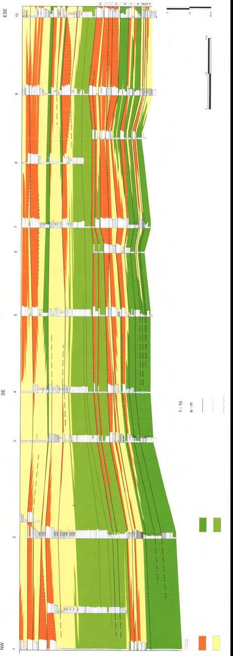
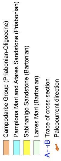

From Mutti and Tinterri., 2009 (original data from Bongiorni, Cattellani, Cotti, Marchi, Sgavetti and Mutti, 1998-1999)
CHAPTER III TURBIDITE SYSTEMS: AN OUTCROP-BASED ANALYSIS 387
Fig. 440
A B mouth-bars deposits and very proximal arenaceous lobes platform facies
sections limits o f recognized units “l ower delta” unit highl y concentrated levels of nummulites er osive surfaces pr oximal and distal arenaceous lobes e xternal platform facies
stratigraphic
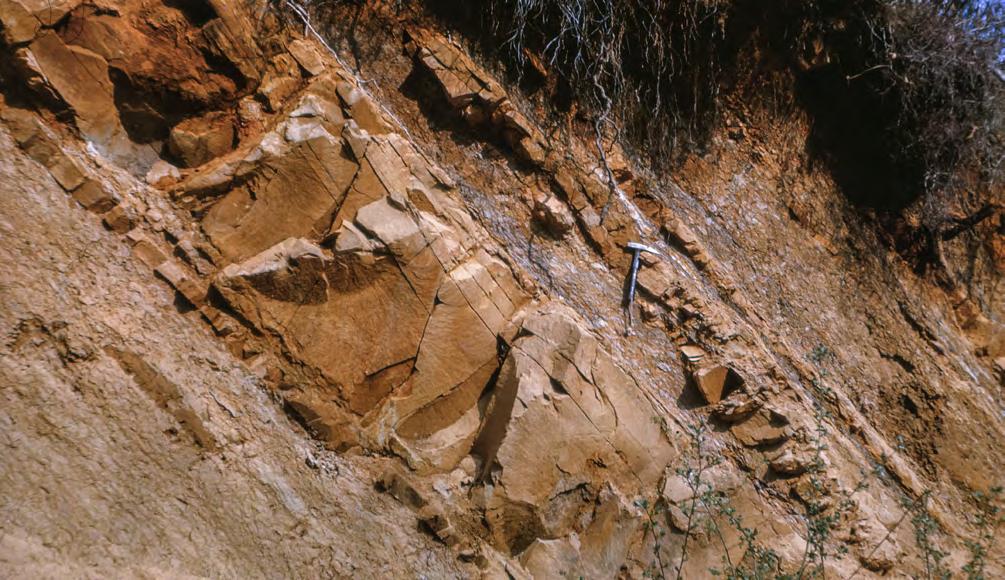
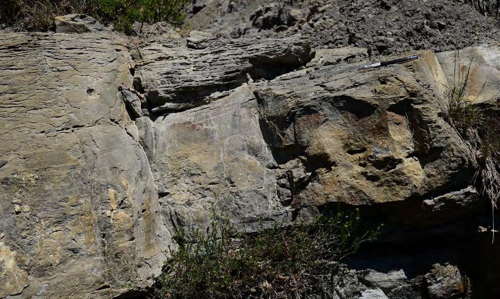
Mudstone clasts
CHAPTER III TURBIDITE SYSTEMS: AN OUTCROP-BASED ANALYSIS 388
Fig. 441 - Example of sandstone/mudstone couplets showing well-developed HCS. Beds are enclosed by bioturbated facies. Upper Cretaceous Grès d’ Alet, eastern French Pyrenees.
HCS
Fig. 442 - Sandstone/mudstone couplet showing a basal division of fine-grained sandstone with HCS, mudstone clasts and scattered skeletal debris, followed upward by a sandy division with current ripples (CR) with an oscillatory component. Eocene Figols Group, southcentral Pyrenees.
HCS
CR
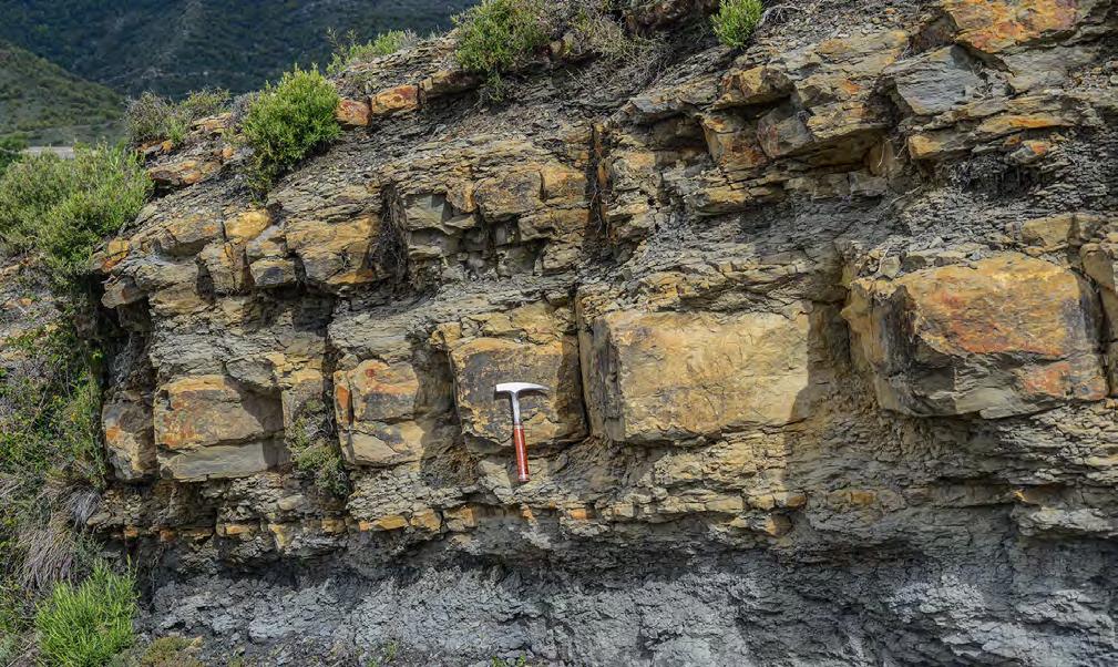
Small-scale features common to both river delta and fan-delta sandstone lobes, and herein thought to be characteristic of shelfal lobe sedimentation, include (see also Mutti and Tinterri, 2009):
• Sharp-based graded sandstone beds with HCS. Whatever the origin of HCS, this structure is very common and is certainly unrelated to storm activity of high-energy shorelines. These beds are invariably associated witth dense or dilute sediment gravity flows;
• The occurrence, in most cases, of displaced skeletal material within coarse-grained structureless divisions or as traction carpets or along lamination surfaces. Some graded beds contain such an abundance of skeletal grains, commonly macroforaminifera and molluscks that, it is tempting to call these deposits hecatomb layers (Figure 444) i.e., layers recording the death of billions or trillions of small benthic organisms ripped up, incorporated and
transported by highly erosive, truly catastrophic hyperpycnal flows. Small mudstone clasts can also be locally abundant (Figures 445 and 446). Both skeletal material and mudstone clasts suggest that hyperpycnal flows underwent substantial bulking through bed erosion after entering seawater, thus increasing their density. Mudstone clasts were rapidly disaggregated to increase the mobility of the flow; skeletal material (commonly macroforaminifera in most of the studied examples) was first suspended in the flow and because of subsequent flow deceleration started to settle from the suspension giving way to tractional bed forms at the base of the beds. These bedforms include structureless divisions associated with thick traction carpets (probably supercritical features) (Figures 447 and 448) and laminated divisions, which are typically found at the base of fine-grained sandstone beds with HCS and thought to be the product of deposition from subcritical flows (Figure 449);
CHAPTER III TURBIDITE SYSTEMS: AN OUTCROP-BASED ANALYSIS 389
Fig. 443 - Thin sandstone lobe made up of a limited number of beds. Note pervasive bioturbation. Eocene Figols Group, south-central Pyrenees.
• Ball-and-pillow structures are very common in sandstone strata with HCS (Figures 450 and 452). This feature is interpreted as the result of foundering of unevenly distributed sediment load (hummocks and swells) of aggrading sand beds on water impregnated mudstones, indicating a synsedimentary origin and high rates of mud deposition;
• The pervasive occurrence of Ophiomorpha burrows (Figure 453);
• Plant fragments may be locally abundant; The generally limited thickness of mudstone (clay and silt) divisions, suggesting that most of the finest portion of the sediment load was still bypassing and moving toward the prodelta region.
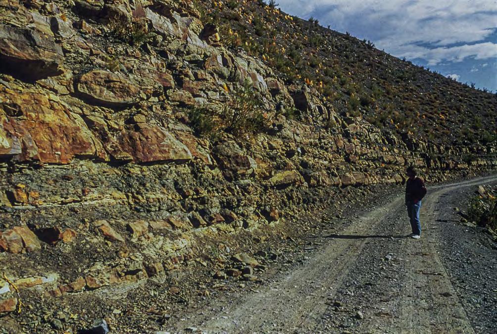
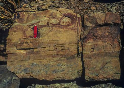
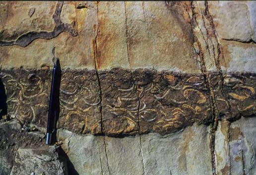
CHAPTER III
SYSTEMS: AN OUTCROP-BASED ANALYSIS 390
TURBIDITE
Fig. 444 - Example of a hecatomb layer in a tabular sandstone lobe. Note HCS above a basal division made of Trigonia shell. Jurassic Bardas Blancas, Neuquén Basin.
HCS
Trigonia shells
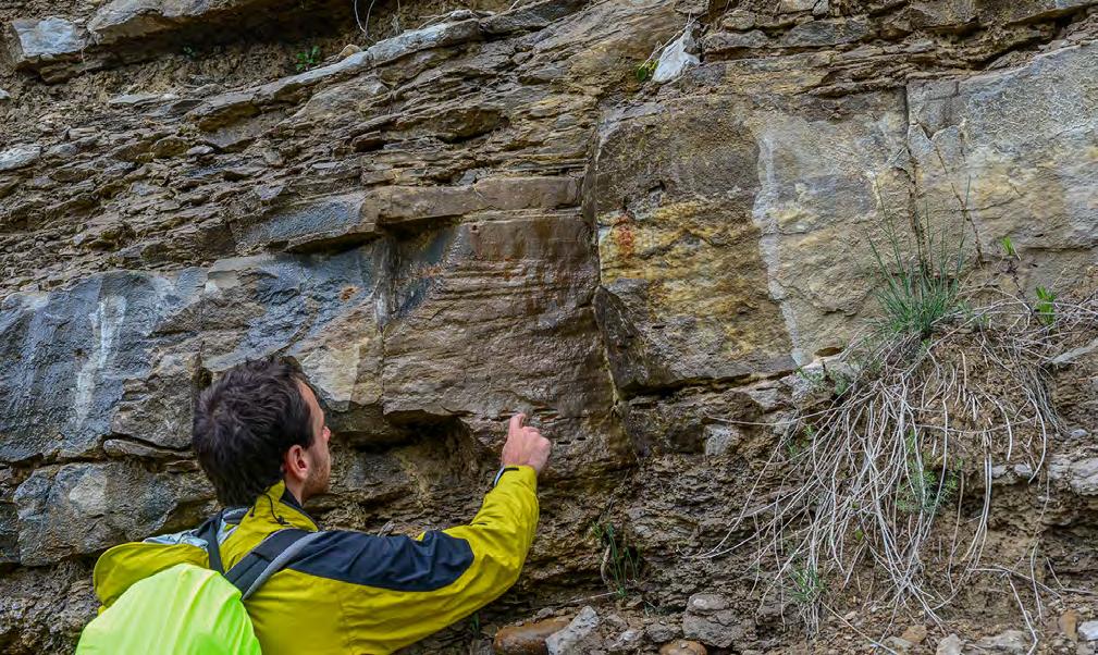
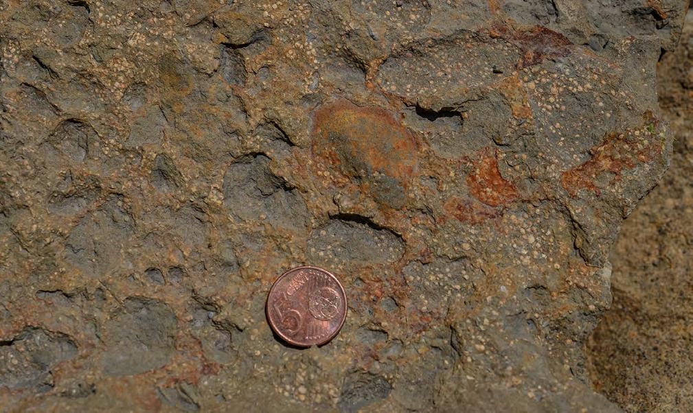
CHAPTER III TURBIDITE SYSTEMS: AN OUTCROP-BASED ANALYSIS 391
Fig. 445 - Mudstone clasts aligned along lamination surfaces at the base of a sandstone bed with HCS. Note the association of mudstone clasts with a shallow scour. Eocene Santa Liestra Group, south-central Pyrenees.
HCS
Fig. 446 - Larger foraminifera and well-rounded mudstone clasts at the base of a fine-grained sandstone bed with HCS. Eocene Figols Group, south-central Pyrenees.
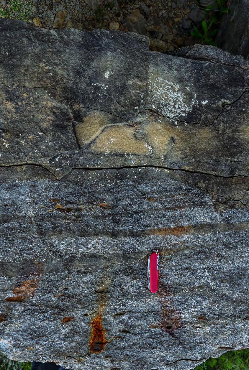
CHAPTER III TURBIDITE SYSTEMS: AN OUTCROP-BASED ANALYSIS 392
Fig. 447 - Skeletal debris comprises a basal coarser-grained structureless division with mudstone clasts overlain by progressively thinner traction carpets in turn overlain by an apparently structureless sandstone division. Eocene Santa Liestra Group, south-central Pyrenees.
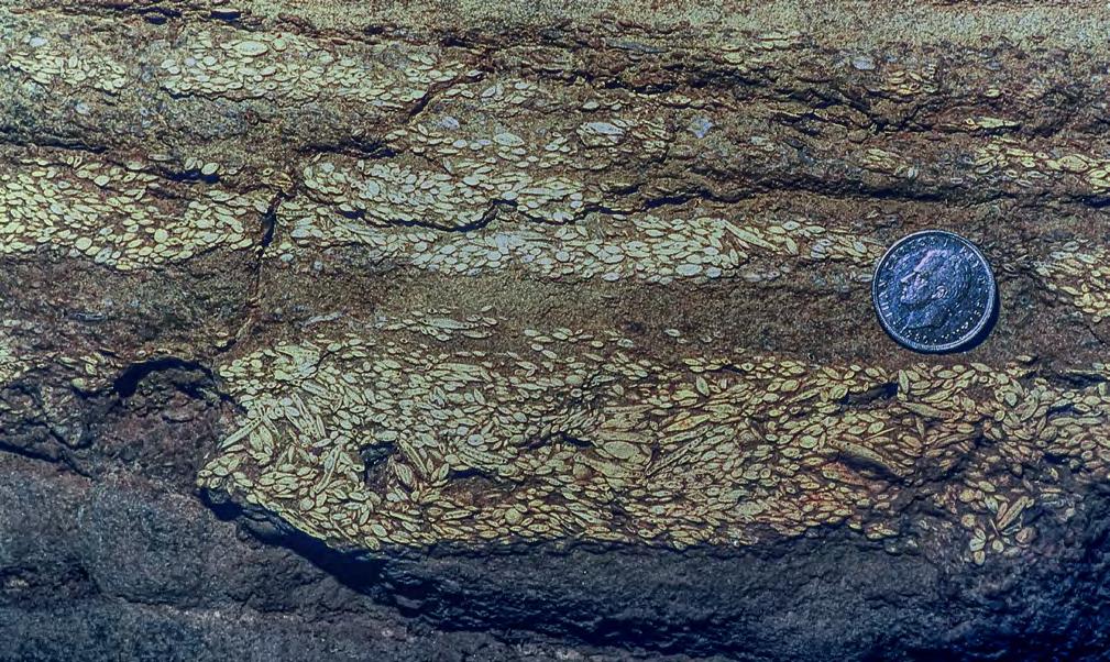
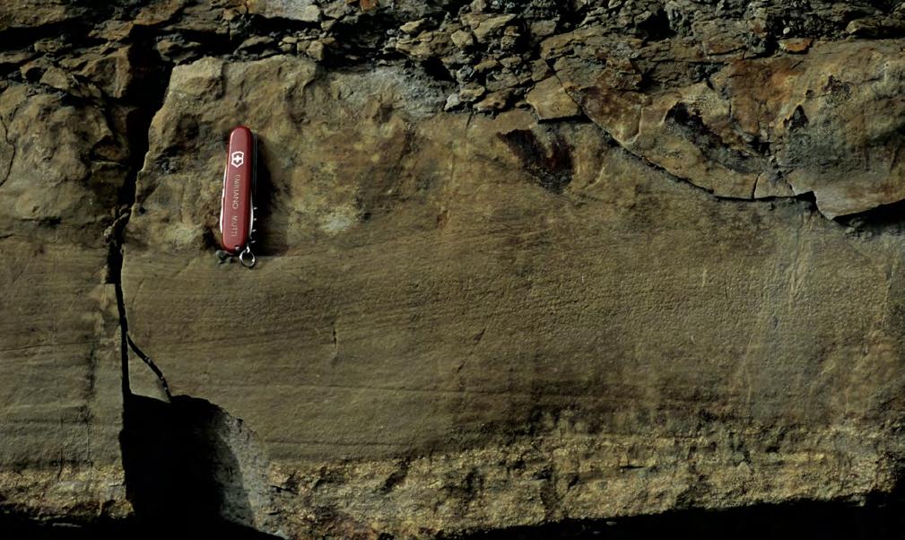
CHAPTER III TURBIDITE SYSTEMS: AN OUTCROP-BASED ANALYSIS 393
Fig. 448 - Typical traction carpets made up of macroforaminifera tests. Eocene Santa Liestra Group, south-central Pyrenees. See text for an interpretation.
Fig. 449 - Example of fine-grained sandstone bed with HCS including a thin basal division of laminated skeletal debris (SkD). The top of the bed is highly bioturbated. Eocene Figols Group, south-central Pyrenees.
HCS
SkD
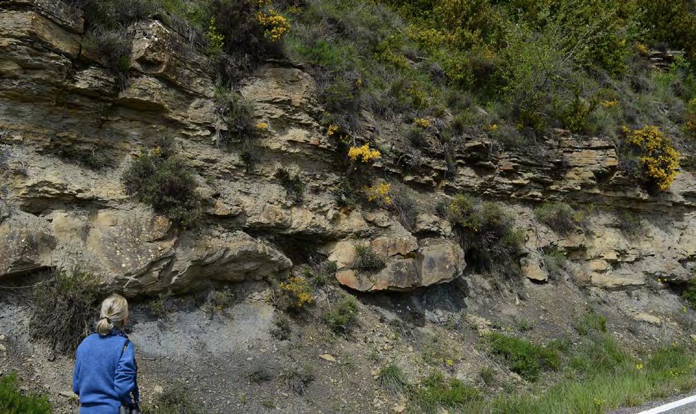
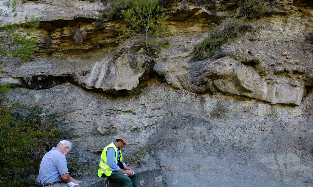
CHAPTER III TURBIDITE SYSTEMS: AN OUTCROP-BASED ANALYSIS 394
Fig. 450 - Ball-and-Pillow structures (yellow arrows) in a thin sandstone lobe sharply resting upon mudstones and overlain by a prograding mouth bar (MB) deposit. Eocene Figols Group, south-central Pyrenees.
MB SL
Fig. 451 - Ball-and-Pillow structure at the base of a thick sandstone bed with HCS. Note the underlying thick succession of mudstone into which the structure could form. Eocene Santa Liestra Group, south-central Pyrenees.
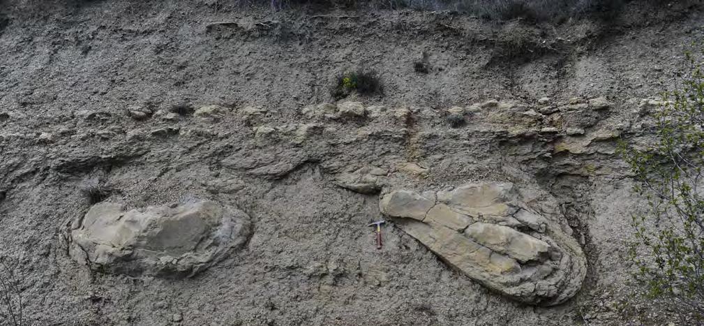
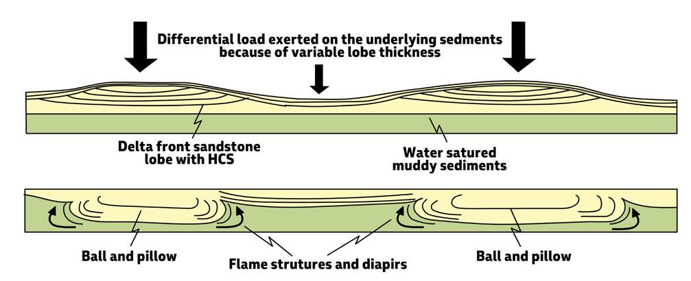
VIII.3.3.4 – The prodelta element
These sediments are the finest grained and most distal expression of river delta or fan-delta systems recording deposition of typically mudstone-dominate successions in shelfal and slope regions. The characteristics of prodeltaic elements are highly variable mainly as a function of the amount of fines contained in river outflows, rates of sedimentation, marine diffusion processes and basin physiography. In orogenic belt basins, these sediments accumulate as essentially tabular units where sufficiently wide shelfal regiions are available. Most commonly, however, and following rapid deltaic pro-
gradation, they form thick sedimentary wedges of delta-slope mudstones. These wedges, connecting shelfal with basinal domains, have been briefly described in Chapter II as the slope element of turbidite systems.
The basic facies types of prodeltaic deposits are primarily thin to very thin siltstone/ or fine sand/mudstone couplets related to river plumes that detach from cannel exits and move seaward as buoyant dilute suspensions (see above). Most of these plumes undergo diffusion convection processes leading to the formation of hyperpycnal flows and deposition of plumites with a great variety of bed types (see above).
CHAPTER III TURBIDITE SYSTEMS: AN OUTCROP-BASED ANALYSIS 395
A
Fig. 452 - A. Detached balls and pillows. B. Scheme showing the process leading to the formation of ball-and-pillow features (from Mutti and Tinterri, 2009).
B
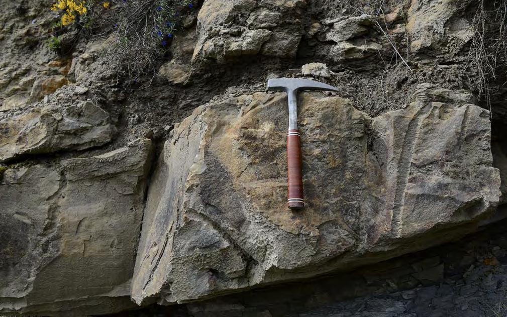
For low rates of sedimentation prodeltaic sediments are generally highly bioturbated and, in shelfal settings, may be locally fossiliferous; conversely, if rates of sedimentation are high, which means that buoyant plumes are frequent, most of the details are preserved. This is the case for most delta-slope successions observed in orogenic belt basin fills, which thus need some further comments.
Delta-slope deposits are spectacularly exposed in the Eocene of the south-central Pyrenees, forming the link of fluvio-deltaic and turbidite sedimentation (Mutti et al., 1988, 2003) (Figure 454). Essentially these sediments consist of mudstone-dominated successions reaching thicknesses up to several hundred meters and made up of four basic and alternating types of facies, commonly forming m-thick packets (see also Chapter II):
mm- to cm-thick siltstone/ or fine sand/mudstone couplets herein interpreted as typical plumites (Figure 455);
• m-thick packets of thin to medium bedded finegrained sandstone (Figure 456) with ripple lamination. Each sandstone is transitionally capped by a thin mudstone division and the resulting sand/ mudstone couplet can be interpreted as the deposit of a relatively dilute hyperpycnal flow, i.e., a turbidity current. These currents can be either flows derived from buoyant plumes (plumites) or the distal and more dilute extension of denser hyperpycnal flows that formed sandstone lobes more landward. In both cases, this facies records periods of time during which rivers were carrying large amounts of fine-grained suspended load through flooding;
CHAPTER III TURBIDITE SYSTEMS: AN OUTCROP-BASED ANALYSIS 396
Fig. 453 - Ophiomorpha burrows (yellow arrows) are very abundant within the graded sandstone beds of lobe elements. Eocene Figols Group, south-central Pyrenees.
• chaotic units made up of nearly in-situ surficial creeping of a limited number of beds and showing the characteristics of rotational slumps (see Chapter II), and mass-flow deposits including sediments and skeletal material derived from a nearby shelfedge (Figures 457 and 458).
Essentially similar facies associations can be observed in the beautiful mudstone-dominated successions of the Jurassic Los Molles Formation, in the Nequen basin (Figure 459).
As mentioned in Chapter II, in highly tectonically mobile basins, as for instance that of the Eocene Castissent Group in the south-central Pyrenees, delta-slope and shelf-edge sediments can experience large-scale slope failures leading to the formation of submarine erosional unconformities. A spectacular example of this kind of unconformities is shown in Figures 460 and 461.
Delta-slope deposits may bear many similarities with both inner and outer levee facies associated with turbidte channels cut into slopes. Care must therefore be taken in interpretations of outcrop of limited extent and not clearly framed within their stratigraphic context. Turbidite channel-levee sediments can be recognized only if associated with channel deposits that may be part of the same exposure or can be documented within the same stratigraphic interval. It is my strong conviction that many delta-slope sediments have been mistaken for turbidite channel-levee facies simply on the basis of the occurrence of thin sandstone beds even in the absence of channels.
A final consideration concerns the spectacular cyclicity displayed by delta-slope deposits (Figure 462) and expressed by the variations in bed thickness and sandstone/mudstone ratio through time. Careful examination of well-exposed successions is probably a fundamental key to try to understand the variations of the fluvial regime through time in terms of frequency and
magnitude of buoyant plumes as mainly related to climate changes.
VIII.3.4 – Reworking by tides and waves
Reworking of fluvio-marine deposits by marine processes in shallow water is essentially restricted to tides and wave action. Modifications imparted by these processes can be so important in many modern deltas that the final configuration of the system becomes that described by Coleman and Wright (1975) and Galloway (1975) for their tide- and wave-dominated deltas (see above). The fluvial signature becomes very weak and most of the sediment accumulates under the control of tides or waves. Modifications imparted by marine diffusion processes can thus vary from the total obliteration of the original fluvial character to an association of features that, in variable proportions and at different scales, indicate the co-existence of both fluvial and marine processes.
In exposed orogenic belt basin fills, wave action is generally reduced by basin size and configuration. As a consequence, reworking by wave is limited; conversely, reworking by tides is common in most basin fills, particularly during transgressive periods. During these periods, tides move landward being confined and amplified within valleys previously incised by fluvial processes during lowstands of sea level. These settings, commonly referred to as “incised valleys”, thus record an initial phase of erosion and subsequent infill by fluvial processes followed by mixed fluvio-tidal sedimentation accompanying sea level rise. Many papers have described in detail this kind of sedimentation with particular emphasis on the estuary stage, i.e., when sedimentation takes place in transgressive embayments dominated by tides and minor fluvial input (see summary in Darlymple, 2010, with references therein).
CHAPTER III TURBIDITE SYSTEMS: AN OUTCROP-BASED ANALYSIS 397
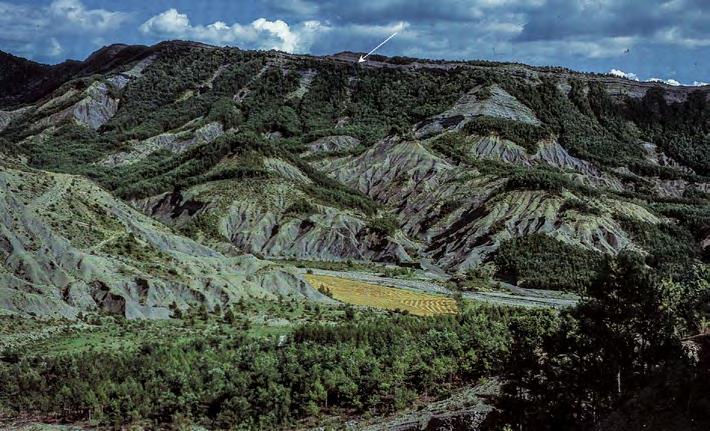
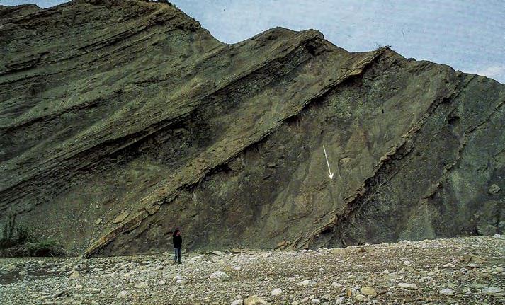
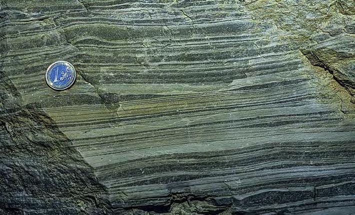
CHAPTER III
398
TURBIDITE
SYSTEMS: AN OUTCROP-BASED ANALYSIS
B A C
Fig. 454 - Delta-slope element (Eocene Castissent Group, south-central Pyrenees).
Delta Front
Delta Slope
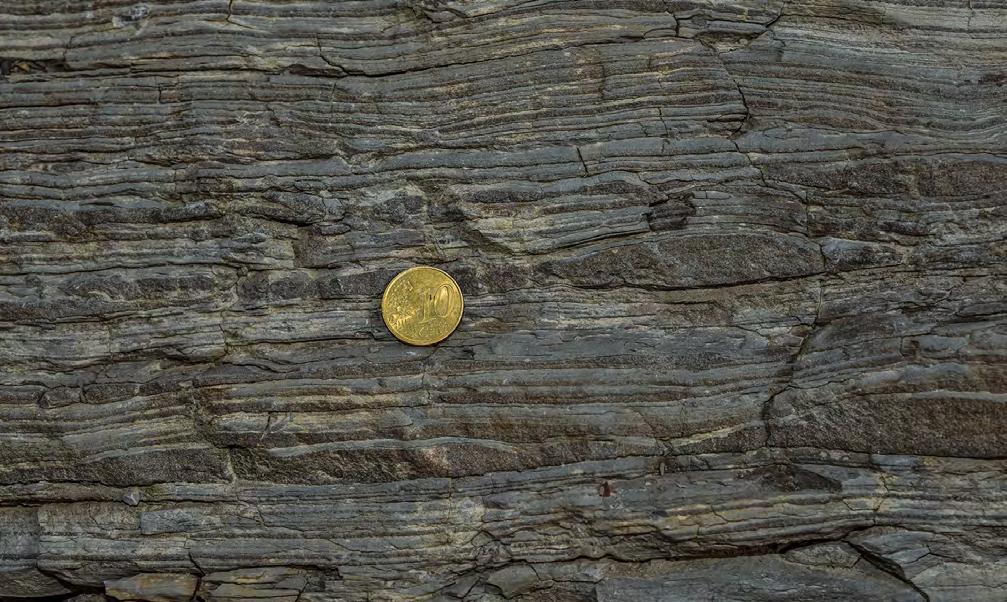
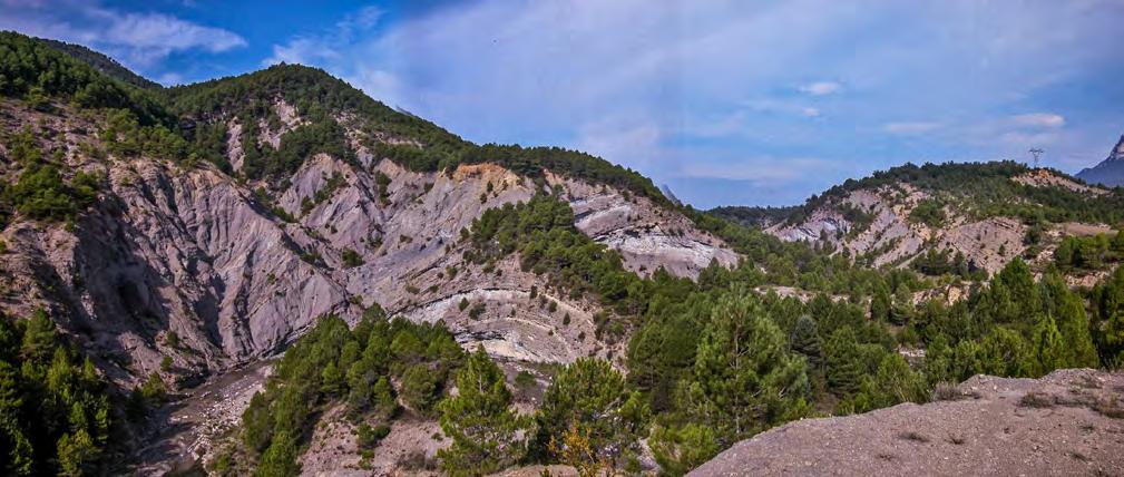
CHAPTER III TURBIDITE SYSTEMS: AN OUTCROP-BASED ANALYSIS 399
Fig. 455 - Thin to very thin siltstone/mudstone couplets interpreted as a typical deposit of buoyant river plumes (plumites, see text). Eocene Castissent Group, south-central Pyrenees.
Fig. 456 - View of delta-slope sediments with indicated (yellow arrow) m-thick packets of thin-bedded sandstone; lighter color units are mudstone-dominated plumites. Note a thick chaotic unit in the left. These sediments were deposited in a highly tectonicallymobile setting during the early stages of growth of a thrust-related anticline (the core of the structure is visible in the center of the photograph). Eocene Castissent Group, south-central Pyrenees.
Chaotic unit
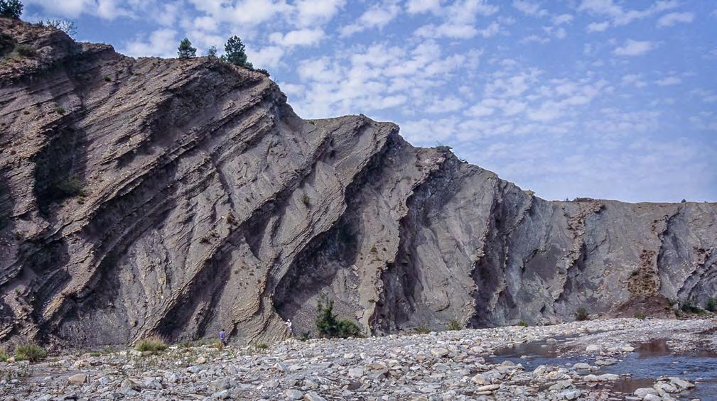
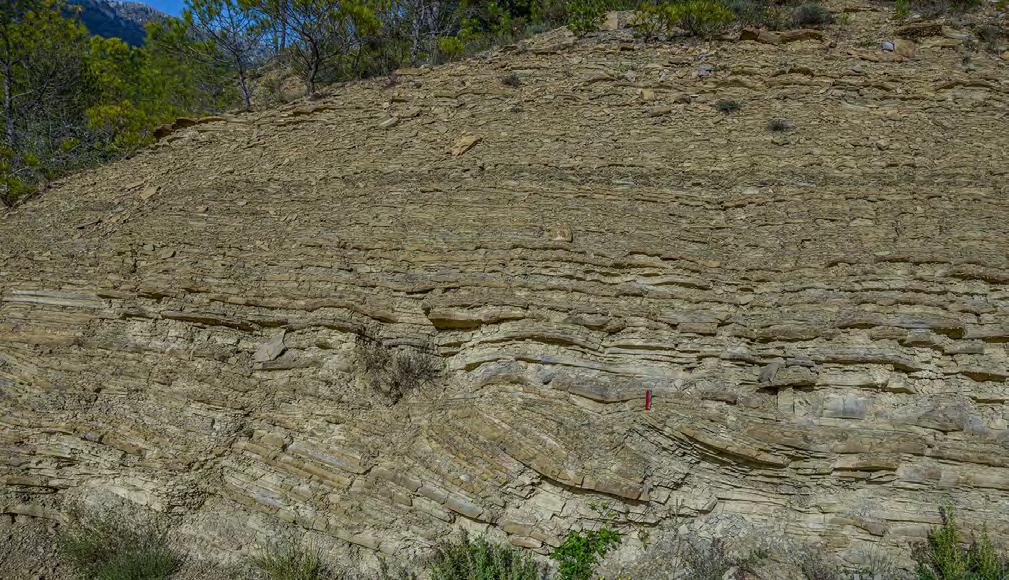
CHAPTER III TURBIDITE SYSTEMS: AN OUTCROP-BASED ANALYSIS 400
Fig. 457 - Typical exposure of delta-slope sediments consisting of m-thick packets of thin-bedded alternating sandstone and mudstone and chaotic units. The entire succession shows evidence of creeping and slumping. Eocene Castissent Group, south-central Pyrenees.
Fig. 458 - Surficial deformation of thin-bedded sandstone/mudstone couplets produced by sediment creeping on a slope. Note how deformation dies out over short distance. The beds draping the feature are typical thin-bedded sandstones with ripple laminae. Eocene Castissent Group, south-central Pyrenees.
Chaotic unit
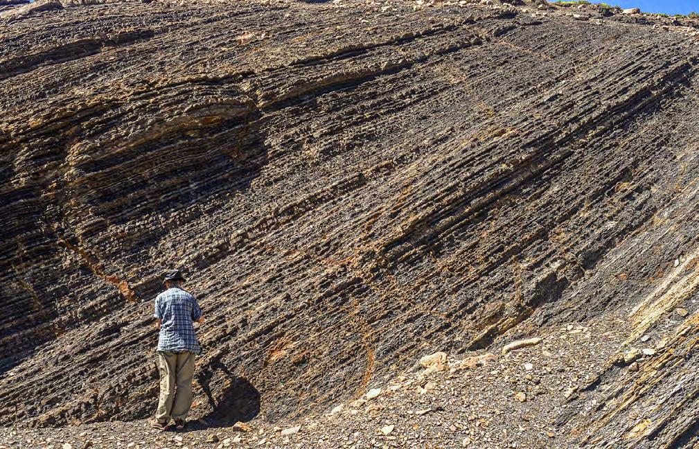
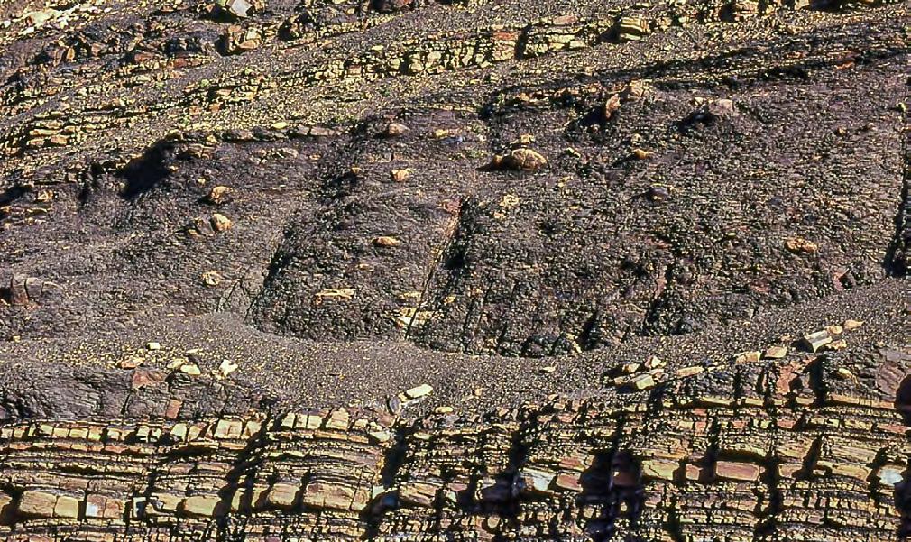
CHAPTER III
401
TURBIDITE SYSTEMS: AN OUTCROP-BASED ANALYSIS
A B
Fig. 459 - A. Thin-bedded plumites; B. Chaotic unit sandwiched between thin-bedded plumites Jurassic Los Molles Formation, Neuquén basin.
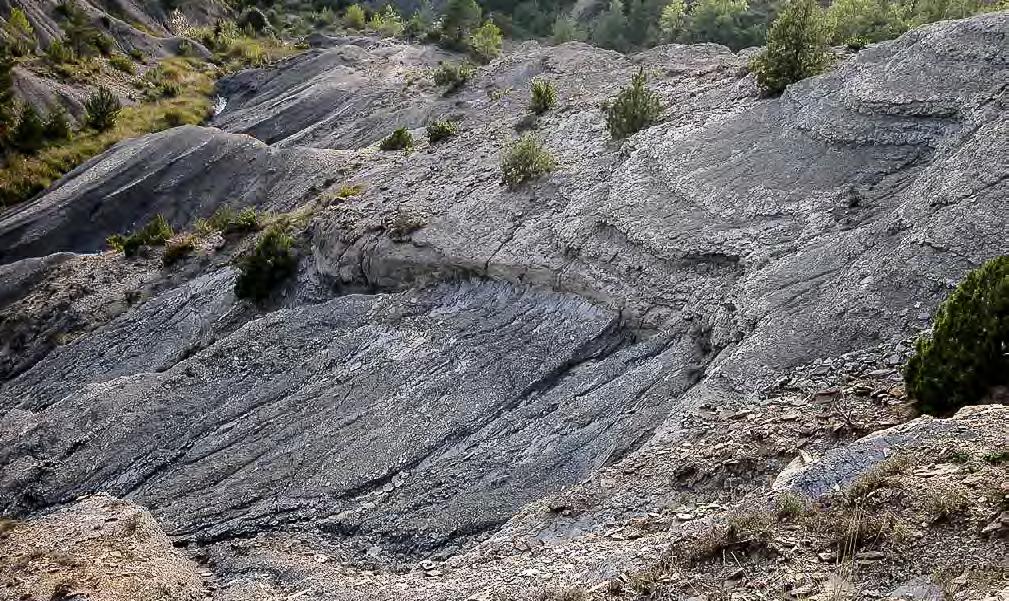
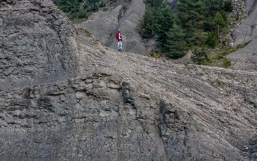
CHAPTER III TURBIDITE SYSTEMS: AN OUTCROP-BASED ANALYSIS 402
Fig. 460 - Spectacular example of submarine unconformity (yellow arrow) produced by tectonic instability. A. Bioturbated and fossilferous shelfal sandstones and mudstones; B. Delta-slope mudstones. Eocene Castigaleu (A) and Castissent (B) groups, South-central Pyrenees.
B B A A
Fig. 461 - View of the unconformity of Figure 460 in a cut roughly normal to the scar surface. Symbols are the same.
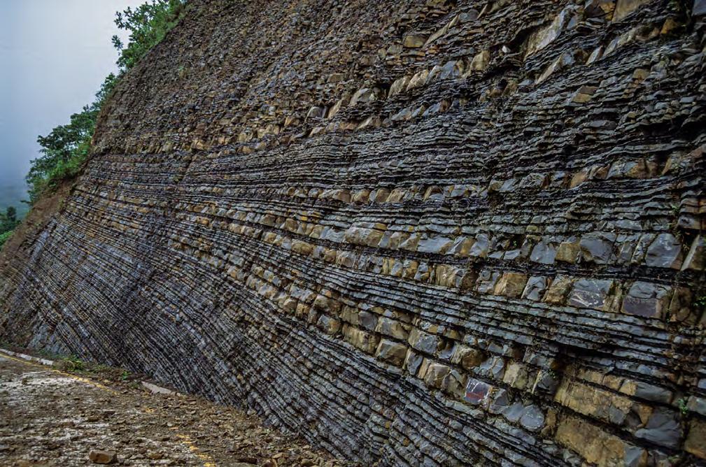
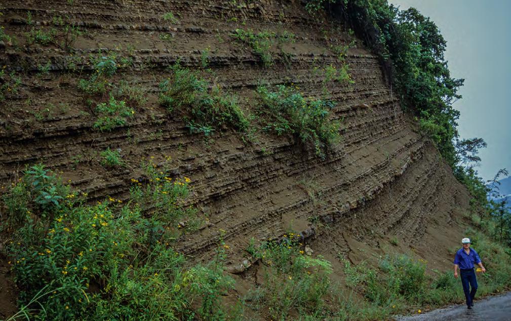
CHAPTER III TURBIDITE SYSTEMS: AN OUTCROP-BASED ANALYSIS 403
A B
Fig. 462 - A. Cyclic stacking pattern of plumites. Note the different aspect of the same stratigraphic unit in a fresh road cut (left) and in a weathered exposure (right). Eocene Chicontepec Formation, Sierra Madre oriental, Mexico (From Mutti, 2019).
In exposed orogenic belt basin fills, tidal reworking may range from true tide-dominated deltas to minor modifications imparted by tidal action down to the scale of individual beds. A very good example of tide-dominated delta in exposed orogenic belt basin fills, and with which I am most familiar, is certainly that of the Eocene Figols Group in the Ager region, south-central Pyrenees (Mutti et al., 1985; Mutti, 2019). The delta is beautifully exposed in the core of a narrow syncline on the footwall of the Montsec thrust (Figure 463) and can be followed over a distance of at least 20 km parallel to the axis of the syncline (for more details see Mutti, 2019). In its ancestral form, the syncline, known as the Ager syncline, was already formed at the time of the Figols deposition, comprising a narrow gulf, the Ager Gulf, opening to west, i.e., toward the Atlantic. This structural setting locally favoured dramatic amplification of tides coming from the ocean. The lowermost part of the Figols Group (FG1) was deposited when the width of the gulf was probably on the order of only 10 km and tides were thus very strong giving way to a macrotidal regime (tidal range in excess of 4 m). The cartoon of Figure 464 shows the simplified three-dimensional stratigraphic setting and the main bounding structural features of the basin (a more detailed scheme parallel to the axis of the gulf and limited to
FG1 and FG2 is shown in Figure 465). This part of the basin fill is essentially composed by m-thick tidal sand ridges, or bars (thickening-upward facies sequences), erosionally overlain by estuarine shoals and associated tidal flats. Fluvial channels flushed sand from the south and south-east and flood tidal currents coming from the west and loaded with skeletal material eroded from offshore regions reworked river-born sands into landward moving tidal ridges with a typical “hybrid” composition (in the sense of De Rosa and Zuffa, 1979), i.e., arenites made up of a mixture of terrigenous and intrabasinal grains, mosty skeletal debris. By contrast, ebb-dominated ridges are characterized by a more terrigenous composition. The internal architecture of one of these bars, as well as its sequence stratigraphic significance are described and discussed in detail in Chapter I (Figure 56). More generally, the depositional model of the tidal bars is shown in Figure 466, emphasizing their progradational character as well as the clear facies subdivision in bar crest, bar slope and bottomset deposits. Higher in the Figols Group succession (FG3, see Figure 2), strength of the tides gradually decreased due to relative sea level rise and related widening of the gulf. The stratigraphically highest Figols strata have only limited tidal reworking and are essentially dominated by fluvial processes.
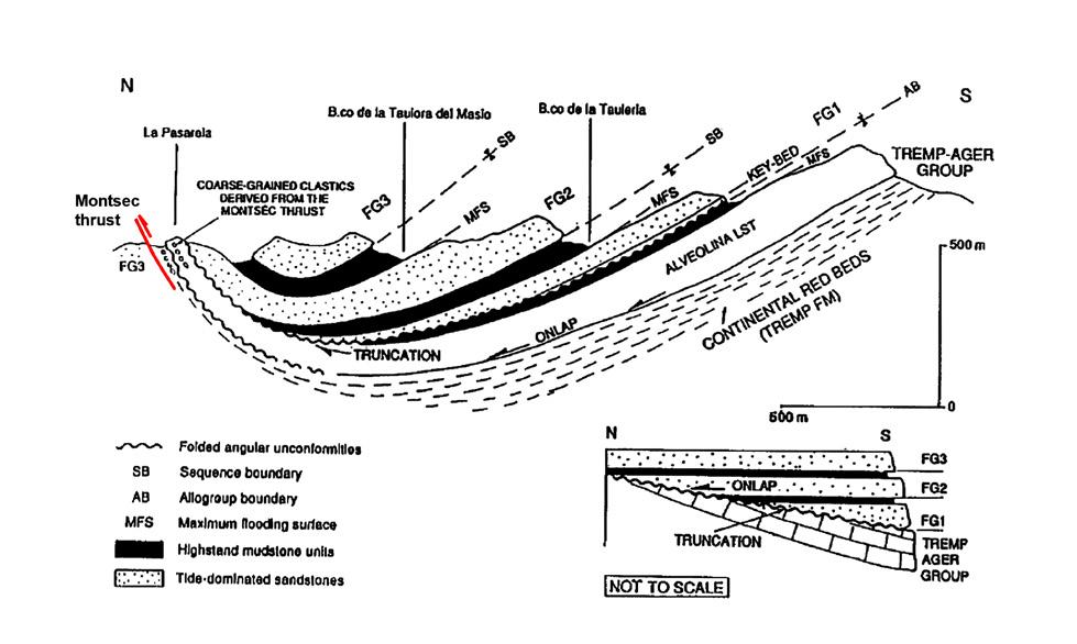
CHAPTER III TURBIDITE SYSTEMS: AN OUTCROP-BASED ANALYSIS 404
Fig. 463 - The asymmetric Ager syncline in the footwall of the Montsec thrust showing the three main depositional sequences that can be recognized in the local Figols succession. Insert (not to scale) shows the stratigraphic setting at the end of FG3 time as well as the basal unconformity of the Figols succession. After Mutti et al. (1994).
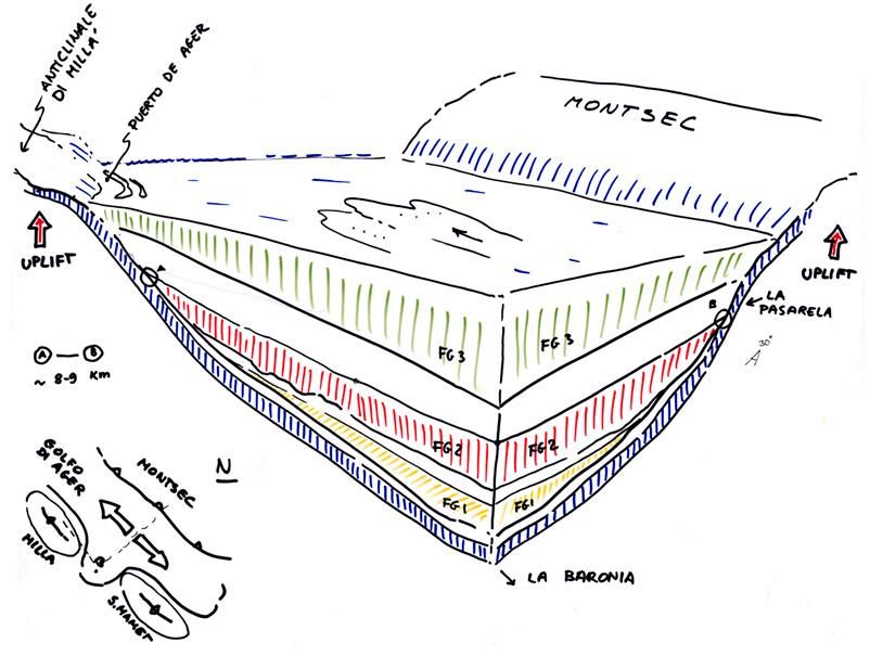

CHAPTER III TURBIDITE SYSTEMS: AN OUTCROP-BASED ANALYSIS 405
Fig. 464 - Cartoon showing a three-dimensional stratigraphic scheme of the Figols Group in the Ager syncline flattened at the top of FG3. The basin was bounded to the north by an ancestral expression of the Montsec thrust and to the south by the growing Milla and San Mamet anticlines (Mutti, unpublished).
Fig. 465 - Stratigraphic cross section showing the FG1 and FG2 strata in a cut parallel to the axis of the gulf of Ager. The FG1 consists of tidal bars; the FG2 is made of estuarine sandstones and tidal flat deposits capped by a maximum flooding surface. After Mutti et al. (1994).
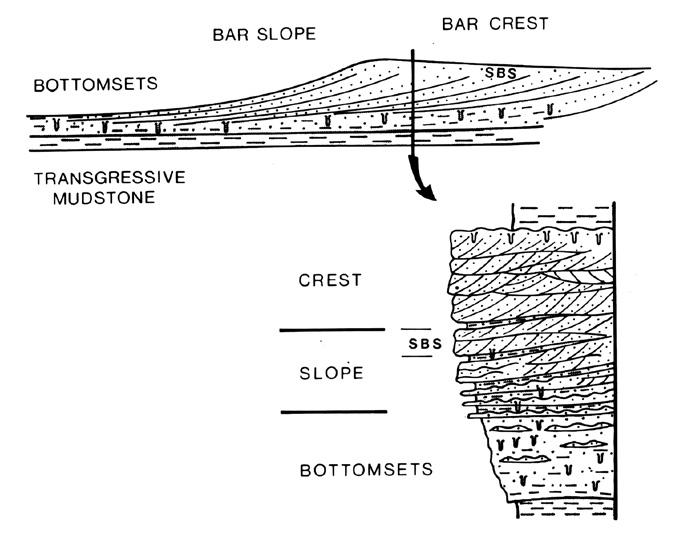
Figure 467 schematically shows another and very interesting example of estuarine deposition from the upper Cretaceous Aren Sandstone, in the south-central Pyrenees. Here, an estuarine sandstone body, approximately 120 m thick and probably related to local structural confinement, consists of an alternation of tidal sandstone bars, formed by both flood and ebb tides, and sharply based conglomerate/sandstone couplets deposited by fluvial floods (Figure 468). The local stratigraphic succession indicates that the estuarine sandstone body overlies subtidal sandstone bars (Figure 469), in turn transitionally overlying alternating shelfal, fine-grained lobes and offshore mudstones (Figure 470). The local facies association can be interpreted according to the scheme of Figure 471, suggesting that the coarsegrained sediment load of fluvial floods was trapped and reworked within the estuary and only a limited portion of the sand load was carried farther seaward by tidal
currents and accumulated in tidal ridges. Only hyperpycnal flows loaded with fine suspended sediment could escape the estuary, probably as plunging plumes, and deposit their load at water depth below that reached by tides. These lobe sediments are made up of subtly graded divisions of coarse siltstone and very fine sandstone. A more detailed and general model for estuarine settings formed in front of flood-dominated river systems is suggested in Figure 472.
Figure 473 illustrates a very clear example of smallscale reworking of fluvial sand by tides in a lagoonal environment. Examples of such settings are very common in transgressive settings. Figure 474 shows tidal sandstone facies with well-developed sigmoidal bedding reworking flood-dominated deltaic facies in the Eocene Roda Sandstone (see Tinterri, 2007 for the general depositional setting).
CHAPTER III TURBIDITE SYSTEMS: AN OUTCROP-BASED ANALYSIS 406
Fig. 466-Depositional model of a tidal bar as inferred from the FG1 strata. After Mutti et al. (1985).
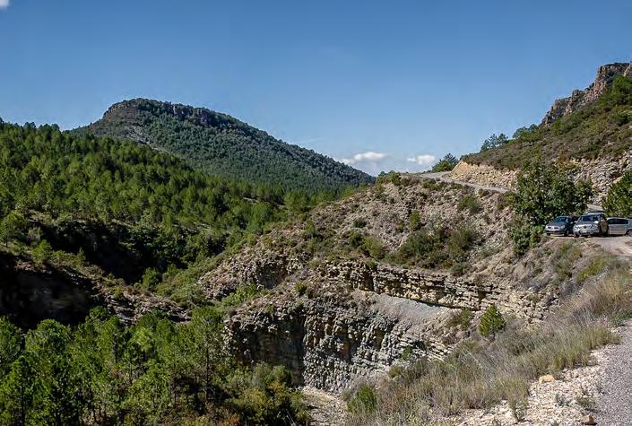
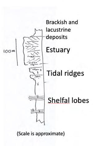
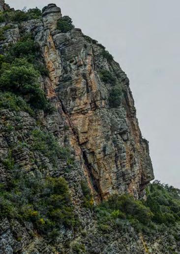
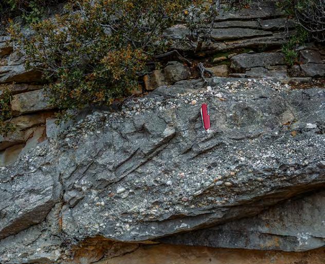
CHAPTER III TURBIDITE SYSTEMS: AN OUTCROP-BASED ANALYSIS 407
Fig. 467 - Stratigraphic succession showing fine-grained tabular sandstone bodies (shelfal lobes) overlain by estuarine, coarse-grained deposits. Tidal ridges (not visible in the photograph) occur immediately below the estuarine sandstones. A sketch of the succession is shown on the left. Upper Cretaceous Aren Sandstone, near Isona, south-central Pyrenees.
Fig. 468 - Estuarine sandstones and conglomerates. Pebbles are deposited by ebb tides and fluvial discharge and partly reworked by flood tides. Tidal bars transitionally overlain by virtually mud-free estuarine sandstones and conglomerates.
Shelfal lobes
Tidal bars
Ebb tide + fluvial
Flood tide
Estuarine sandstones
A A B B
Estuarine sandstones Tidal ridges
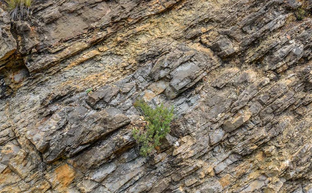
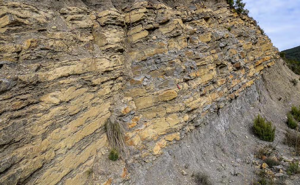
CHAPTER III TURBIDITE SYSTEMS: AN OUTCROP-BASED ANALYSIS 408
Fig. 469 - Close-up of a tidal bar showing sandstones with sigmoidal cross bedding alternating with highly bioturbated finer-grained facies. Mud drapes and clay chips are common.
Fig. 470 - Very fine-grained lobe made up of thin to medium bedded, subtly graded siltstone/mudstone couplets. Siltstone divisions are commonly bioturbated but may show some well-preserved current ripples and sinusoidal laminae. The lobe is encased in thick mudstone units.
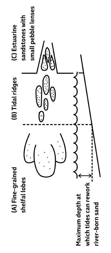
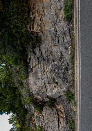
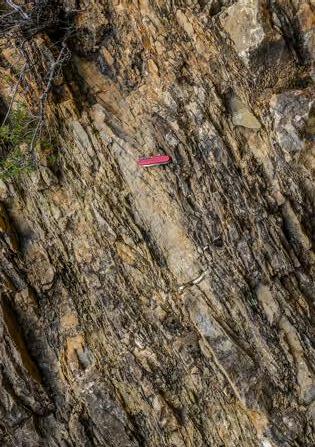
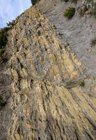
CHAPTER III TURBIDITE SYSTEMS: AN OUTCROP-BASED ANALYSIS 409
Fig. 471
Simplified depositional model inferred from the stratigraphic setting shown in Figure
A B C
6. Upper Cretaceous Aren Sandstone, near Isona, south-central Pyrenees.
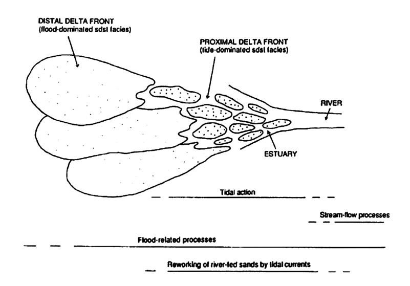

Flood-dominated fluvial point
CHAPTER III TURBIDITE SYSTEMS: AN OUTCROP-BASED ANALYSIS 410
Fig. 472 - Suggested model of an estuarine setting developed in front of a flood-dominated river system. Facies may greatly vary as a function of flood magnitude and tidal range.
Fig. 473 - Outcrop-scale association of tidal and flood-dominated fluvial facies. An ebb tidal delta (seaward direction is to the right), enclosed by lagoonal mudstones, is overlain by a flood- dominated point bar through an unconformity surface recording a small-scale baselevel fall. Eocene Castissent Group, south-central Pyrenees.
Sequence boundary
Ebb tidal delta
Lagoon
Lateral accretion surface
bar
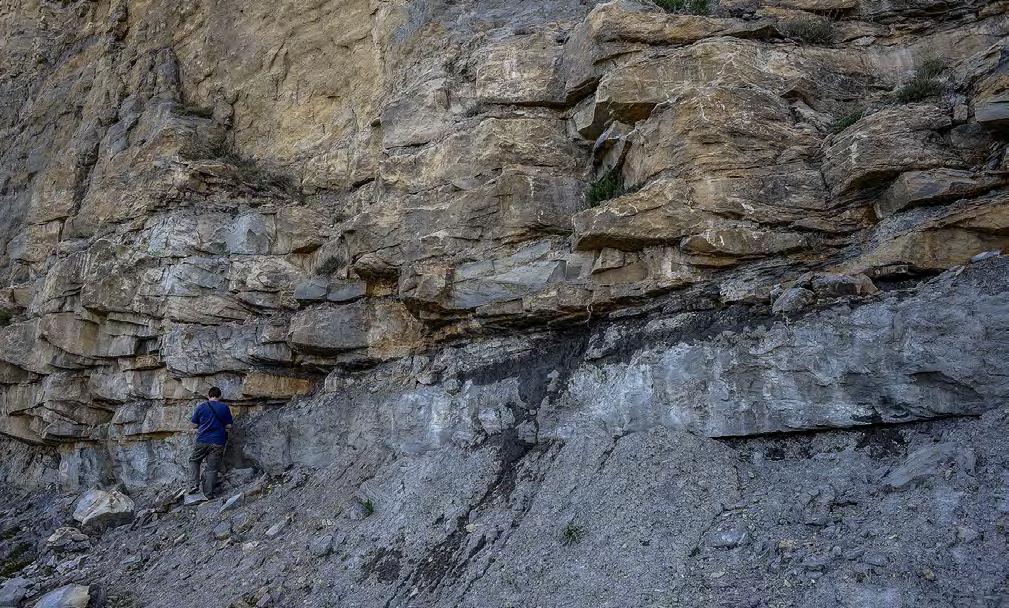
Reworking of flood dominated fluvio-deltaic systems by waves is less common but shares many controlling factors with tidal reworking. Also, in the case of wave reworking, coastal configuration is important to allow for the development of relatively strong wave action; secondly, substantial wave reworking is observable only during periods of relative sea level rise and recession or abandonment of fluvial systems. Examples of wave reworking from the Oligocene Molare Group, Tertiary Piedmont basin, are illustrated in Figures 475-478. In its lower stratigraphic portion, the Molare consists of flood-dominated alluvial fans resting upon a regional unconformity surface. Higher in the section a similarly regional sea level rise and an ensuing transgression forced the transition of alluvial fans into fan-deltas which were eventually capped by marine mudstones. The transition between flood-dom-
inated fan-deltas and the overlying open marine mudstones is recorded by wave-dominated deposits marking the base of the transgression. Though wave action is undoubtful and beach structures are clearly recognizable, yet the general poor sorting of the sediments in the foreshore facies suggests shorelines of relatively low energy. Conversely, ravinement surfaces, along which the shoreline moves landward, are well developed (Figures 476 and 477). Figures 478 and 479 show further examples of wave reworking expressed by pebble alignments indicating transient or more permanent wave action on top of flood dominated facies. A very good example from the upper Cretaceous Aren Sandstone of a delta reworked by strong wave action into a barrier-island system is discussed in the conclusions because of its relevance in terms of sequence stratigraphic analysis.
CHAPTER III TURBIDITE SYSTEMS: AN OUTCROP-BASED ANALYSIS 411
Fig. 474 - Tidal sandstone facies with well-developed sigmoidal stratification reworking the flood-dominated Roda Sandstone delta (see Tinterri, 2007 for details). Eocene Figols Group, south-central Pyrenees.
Transgressve shoreface
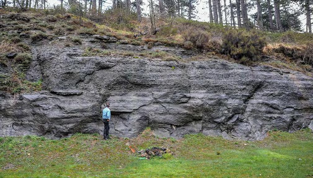
Transgressive surface
Beach (foreshore)
Shoreface
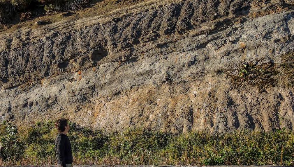
CHAPTER III TURBIDITE SYSTEMS: AN OUTCROP-BASED ANALYSIS 412
Fig. 475 - Conglomerates and sandstones deposited by wave action and reworking alluvial fan deposits (essentially a wave-dominated fan-delta front). Note seaward (left) gently-dipping cross strata (foreshore) overlying a sandy shoreface without bioturbation. The blue surface is a transgressive surface marking the transition to fossiliferous and highly bioturbated shoreface deposits. Oligocene Molare Group, Tertiary Piedmont basin.
RS RS
Fig. 476 - Alluvial fan sediments reworked by wave action during a transgression. The alluvial fan deposits are overlain by lagoonal sediments with oysters and washover sandstones, in turn overlain, through a ravinement surface (lower RS), by low-energy foreshore deposits. The upper ravinement surface marks the transition to a transgressive highly fossiliferous shoreface. Seaward direction is to the left. Oligocene Molare Group, Tertiary Piedmont basin.
Shoreface Beachface LAGOON WASHOVER RS
ALLUVIAL FAN
Shoreface
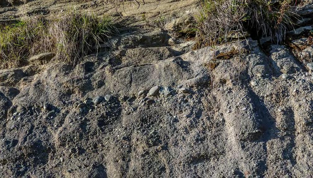
Ravinement surface
Low-energy foreshore
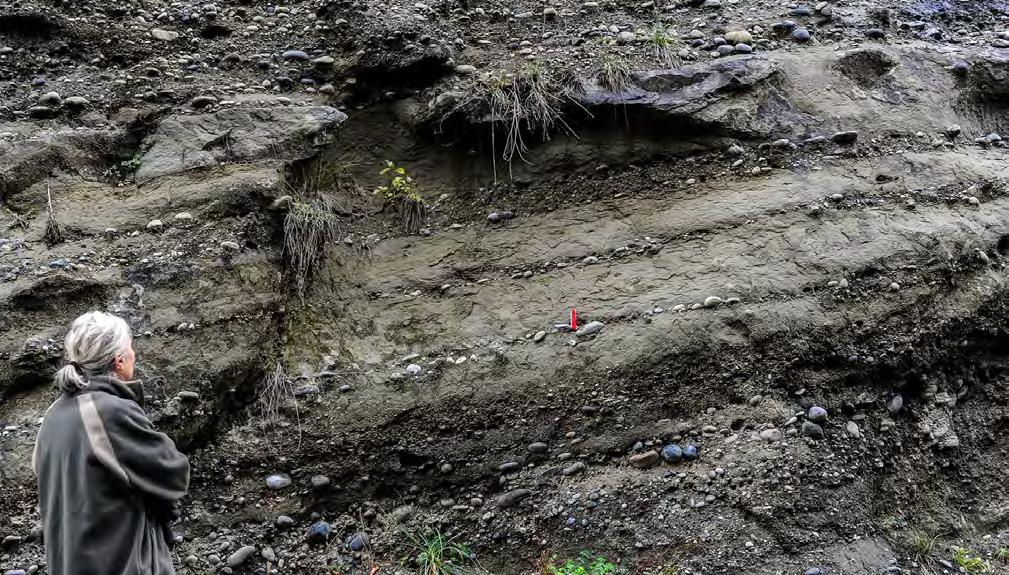
CHAPTER III TURBIDITE SYSTEMS: AN OUTCROP-BASED ANALYSIS 413
Fig. 477 - Detail of Figure 476 showing the upper ravinement surface. Note the angle between the foreshore strata and the overlying ravinement surface.
Fig. 478 - Pebble alignments produced by wave action and associated graded flood units in a fan delta system. Oligocene Molare Group, Tertiary Piedmont basin.
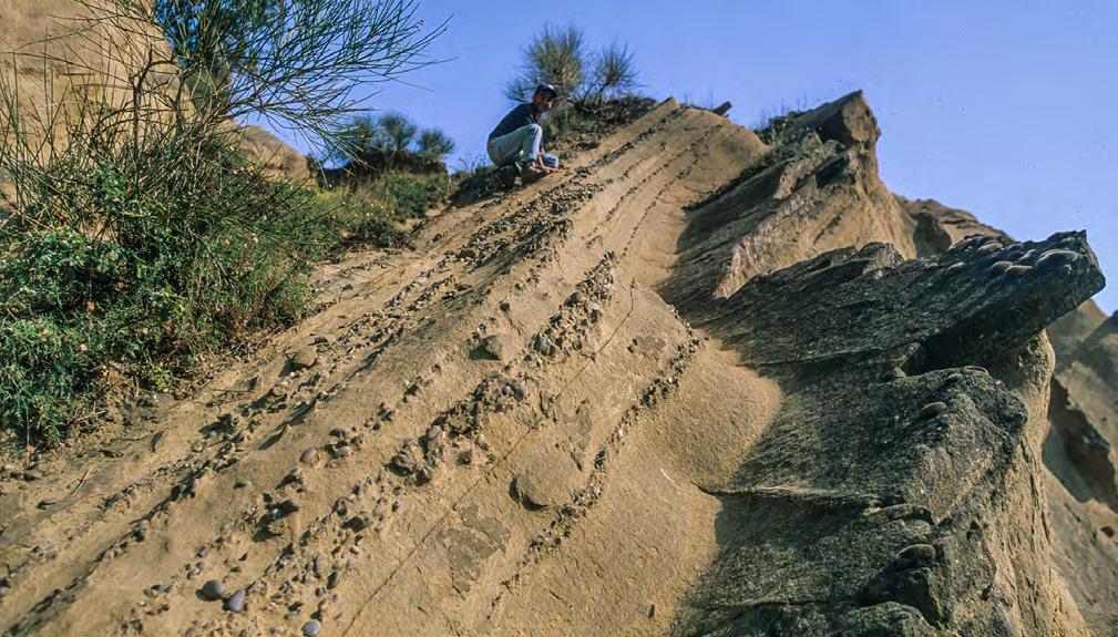
CHAPTER IIIB (CONCLUSIONS AND SOME PERSONAL THOUGHTS)
I – THE IMPORTANCE OF FACIES AND FACIES ASSOCIATIONS
It is my profound conviction that careful analysis of facies and facies associations remains the basic starting point to try to understand what the rocks mean. The many photographic plates of this book attempt to show facies with many examples from different depositional systems dominated by turbidity currents, hyperpycnal flows and rivers in flood. The purposes were to document (1) what rocks look like in the real world, (2) how carefully one has to look at bedding surfaces, grain size, and internal structures, and also (3) trying to convince young students that rocks may be beautiful, even to a layman. Appreciating the beauty of rocks is fundamental to develop a love for sedimentary geology and therefore free your potential talent and improve your skills.
Unfortunately, during the last decades technological progress has tended to shift our interest towards rock
characteristics that are basically inferred from seismic data, laboratory experiments, various types of modelling, and remote sensing. As a consequence, looking carefully at rocks has become a somewhat obsolete exercise. What I mean by “looking carefully” is simply looking at rocks without preconceived ideas, forgetting about models and assuming that rocks have still something to tell us in addition to (and, in some cases, I would say even in spite of) what we already know about them. My point is that what we know is less than 30% of what we could extract from them (see later) and “looking carefully” means exploring what is still unknown. This may lead to find something different from existing models and, in most cases, not to have an explanation for it. Nonetheless, we have found a new problem that future research will try to solve. Turbidites and flood-dominated deposits are an ideal field of research if viewed in this perspective.
More than any thing else, the great number of papers dealing with turbidity currents and their deposits highlights the popularity of the problem and its complexity. Oil exploration into deep waters has been certainly one of the main reasons for this research effort.
CHAPTER III TURBIDITE SYSTEMS: AN OUTCROP-BASED ANALYSIS 414
Fig. 479 - Beach sandstones (pebble alignments) overlying deltaic deposits following delta lobe abandonment or sea-level rise. Pliocene Sant’Arcangelo basin, southern Italy.
Beach Deltaic
After an initial period during which facies were essentially described in simple terms of lithology, texture and internal sedimentary structures, research moved towards progressively more sophisticated approaches aiming at understanding the processes governing turbidite sedimentation and improving our ability to predict facies distribution patterns in deep-water systems. The basic and descriptive facies model of Bouma (1962) was retained as a reference, but many other facies have been introduced with time to show the possible departures from it. Gradually, a processes-oriented approach started to prevail along with the tendency to put emphasis on processes rather than on rock characteristics. These problems are amply reviewed in Chapter II.
Monitoring of modern turbidity currents in the oceans and laboratory experiments have added useful information about possible triggerings of these currents (e.g., Parson et al., 2001; Hizzett et al., 2017; Paull et al., 2018) in addition to those discussed at length in a fundamental paper by Piper and Normark (2001), and the complex flow transformations taking place in the channel-lobe transition zones (Sumner et al. 2013; Dorrell et al., 2016), in addition to those identified by Mutti and Normark (1987) and Wynn et al. (2002). In this book emphasis has been put on the importance of rivers in flood as the main trigger of turbidity currents in tectonically active basins because these flood-generated flows dominate deposition also in the marginal fluvial and deltaic systems of the same basins. However, the reader should be aware that in many other geodynamic settings turbidite systems may originate from currents triggered by different processes, particularly by retrogressive slope failures.
Though processes are crucial to understand the origin of a deposit, in the real world we need, however, to work with rocks and therefore with facies and facies associations, and possibly map them within depositional elements and systems in both outcrop and subsurface studies. For these reasons we need a flexible and simple facies scheme to start with. The scheme that has been offered in Chapter II provides a reasonable compromise through which facies can be defined on the basis of objective criteria (mainly texture and internal depositional structures) and contain sufficient information for a preliminary interpretation of their formative processes. The basic facies groups introduced are few and within each of them there is ample room to accommodate a great variety of bed types observed in the system under consideration. Basically, all types of classifications tend to put order on a continuum which is observed in the real world and, accordingly, the scheme thus limits the number of facies to essential types. An improved understanding of the processes
involved can only be obtained through facies associations and the facies tracts that describe them. The work is certainly time-consuming but is worth. Since geological conclusions are always a provisional step, in a following section I will offer a further, though minor, refinement of the scheme of. Chapter II. The refinement is the result of additional thinking about the relationships between hyperpycnal flows and turbidity currents and additional field observations. Once again, the refinement shows that interpreting rocks is an endless process.
As amply discussed in previous chapters, facies, facies associations, depositional elements and systems describe the anatomic pieces of a mappable stratigraphic unit, whilst processes provide the physiologic explanation of the way the final depositional system was built through time. Clearly, a single bed, without its context, is of little help in this difficult assembling of many pieces. Instead, one bed has to be compared to its time-equivalent beds both upcurrent and downcurrent and observations have to be extended to the beds which are above and below. Essentially, we should frame our observations within the context of the Walther’s principle. Facies tracts and lateral and vertical stratigraphic relationships are the fundamental tools in this kind of analysis. Even within an individual bed the same principle holds true for a correct understanding of the relationships between different depositional divisions - a concept that is often overlooked.
The same problem is encountered with flood-dominated alluvial and fluvio-deltaic systems where processes are poorly understood and still matter of many controversies (e.g., Shanmugam, 2019), primarily originated by a poor knowledge of the component facies of these deposits. As discussed in Chapter III, these facies and their associations apparently will require a strong research effort in future years to develop new models for both fluvial and deltaic sedimentation. A re-appreciation of sedimentary structures produced by supercritical flows (e.g., Lang et al. 2017) will greatly enhance our understanding of facies and processes. A first attempt to enter this still largely unexplored world is presented in this book, where the basic observation that genuine festoon bedding (migration of 3D dunes) is absent from most of the examined sediments has led to recognize flood-dominated systems and suggested new possible models significantly different from the classic ones.
Summing up, there are still thousands of exceptional exposures around the world waiting for curious geologists who are not in a hurry and willing to learn from them, provided they use their intellectual freedom.
CHAPTER III TURBIDITE SYSTEMS: AN OUTCROP-BASED ANALYSIS 415
II – SEQUENCE STRATIGRAPHY AND ITS APPLICATION TO FOLD-AND-THRUST BELT BASINS
In previous pages we have amply discussed cyclicity at a relatively small scale and shown its importance for understanding facies changes through time in both turbidite and fluvio-deltaic sediments. Base-level variations, migration of the equilibrium point, sediment flux, type of processes and climate changes have been emphasized as the main local controlling factors. Basically, we have been using sequence stratigraphic principles for framing facies analysis within a broader context.
As the reader has certainly perceived, much more caution, and less enthusiasm, have been used to interpret larger scale cyclicity. The conceptual model that has been preferred is still that of the classic sequence stratigraphy as proposed by Peter R. Vail and his school (e.g., Posamentier and Vail, 1998). The reason is very simple: though with its problems (the main one being in some cases the unambiguous recognition of sequence boundaries!), the model offers a simple way of thinking and framing observations within a logical suite of events essentially based on accommodation cycles developed at various physical and temporal scales and mainly produced by relative sea level (baselevel) variations. These accommodation cycles apparently work from seismic scale down to that of m-thick elementary depositional sequences recognized in outcrop (Figure 480), suggesting a fractal nature of the forestepping-backstepping wedges recording each cycle (Mutti, 2011). Most importantly, the model re-evaluates old concepts like, for instance, transgressions, regressions, unconformities, and depositional systems, with which most geologists are familiar, and emphasizes low and high stands of sea level). Relative sea level lowstands favour turbidite deposition in deepwater. Figures 481 and 482 show simple expressions of these sequence stratigraphic concepts that can be easily observed in small scale modern settings.
The model has proven to be very useful for the seismic interpretation of divergent margin settings, from which it has been derived. More caution has to be taken in the application of such model in the analysis of tectonically active margins where tectonics plays a major and still poorly understood role in the repetition of accommodation cycles at local and regional scale.
Sequence stratigraphic concepts have been primarily devised for their application at a seismic scale and therefore for stratigraphic units of sufficient thickness to allow for their seismic resolution. These thicknesses are generally those produced by accommodation cycles referred to as 3rd order cycles and resulting into the classic depositional sequences (Chapter I). In some cas-
es, and by integrating good seismic and well-log data, higher-order cycles (fourth order) and sequences can be identified, provided they have sufficient thickness. 3rd order depositional sequences can be best understood where seismic regional data can display them over a sufficient extent to include alluvial, shelf, shelfbreak and slope-basinal elements. Generally, these seismic data are from 2D surveys and do not have enough resolution to allow for the identification of small-scale sequences. Conversely, 3D seismic data have better resolution but fail to show the regional context.
In field studies you generally have great detail (resolution) at small and medium scale but also a lack of seismic-scale control to better frame your local observations. Regional, large-scale reconstructions of a basin fill strictly based on field data require much time and usually remain questionable (see later). Honestly, I cannot see the way we can reconcile these two different points of view at present.
Since this book has been largely written on the basis of my field experience gathered from studies in orogenic belt basins and is mainly intended to share with young people my approach to facies and stratigraphic analyses, I would say that for practical purposes the hierarchical classification of Figure 54 (Chapter I), which is strictly based on a physical scale, works quite well. It encompasses unconformity-bounded units from their elementary expression (elementary depositional sequences) up to increasingly more complex units such as large-scale composite depositional sequences and allogroups (see Figure 23, Chapter I). It accepts the way rocks look like in the field and simply requires that facies and unconformity surfaces be carefully recognized. The hierarchical scheme does not have the ambition to answer questions such as the origin of the cycles, nor how much time is involved in each of them. The classification is strictly intended as a tool for local and regional basin analysis.
Being derived from basin fills that formed in tectonically very active settings, accommodation cycles are certainly controlled by a variety of factors and their feedbacks, clearly including, among others, tectonic uplift and subsidence and depocenter mobility. You should be aware of this, but, in the practice, it will be impossible to single out the relative importance of each of these factors for all the units that comprise a basin fill. However, where sufficient detail is available, the tectonic signature can be detected even at small and medium scale, i.e., the scale of elementary depositional sequences (EDSs) and composite depositional sequences (see below), and this signature is even more obvious for the allogroup boundaries, which are marked by angular unconformities.
CHAPTER III TURBIDITE SYSTEMS: AN OUTCROP-BASED ANALYSIS 416
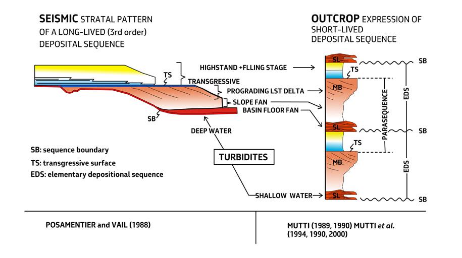
Problems arise when assembling small-scale units into larger scale sequence stratigraphic units. The scheme of Figure 55 (Chapter I) simplifies these problems by introducing large-scale composite depositional sequences and allogroups, regardless of their actual significance within the more conventional concepts of sequence stratigraphy. This scheme may be good for practical purposes, but certainly fails or does not attempt to recognize regional or global cycles of accommodation, say in the range of the 3rd order, that should be expressed by suites of distinctive systems tracts and their bounding surfaces. The lack of seismic-scale architecture of basin fills is actually a limiting factor for more significant sequence stratigraphic interpretations in highly tectonically controlled settings.
The basic issue behind these difficulties, which is well beyond our more limited and practical scope, is discussed at length by Catuneanu (2006) and essentially restricted to the tectonic and orbital controls on global, regional and local eustatic fluctuations (Chapter I, Figure 16). Stated in more pragmatic terms and restricted to thrust-and-fold belt basins undergoing syn-sedimentary structural deformation, the problem resides in separating tectonically controlled accom-
modation cycles of local significance (e.g., step-wise thrust propagation, active faulting, local uplift and subsidence) from global and regional accommodation cycles produced by sea level fluctuations, which in their turn are controlled by tectonism and orbital forcing. At present, this separation is highly problematic and will remain such in a near future.
A very promising approach is that of cyclostratigraphy and “astrocyclicity” (Strasser et al., 2006, with references therein) that uses astronomical cycles of known periodicity to date and interpret the sedimentary record in the range of Milankowitch cycles (20 to 400 my and even up to millions of years). Once the relationship between the sedimentary record and the orbital forcing is established, very accurate astronomical time scales can be established, though still restricted to the younger part of the stratigraphic record. The assumption behind the approach is that orbital cycles (precession, obliquity and eccentricity) induce changes in insolation that result in climatic and oceanographic changes potentially recorded in the stratigraphic record (e.g., cyclic stacking patterns, facies changes, unconformity surfaces). Most of the small-scale cyclicity that we have discussed in previous pages certainly pertains to the Milankowitch range.
CHAPTER III TURBIDITE SYSTEMS: AN OUTCROP-BASED ANALYSIS 417
Fig. 480 - The fractal nature of depositional sequences (from Mutti, 2011).
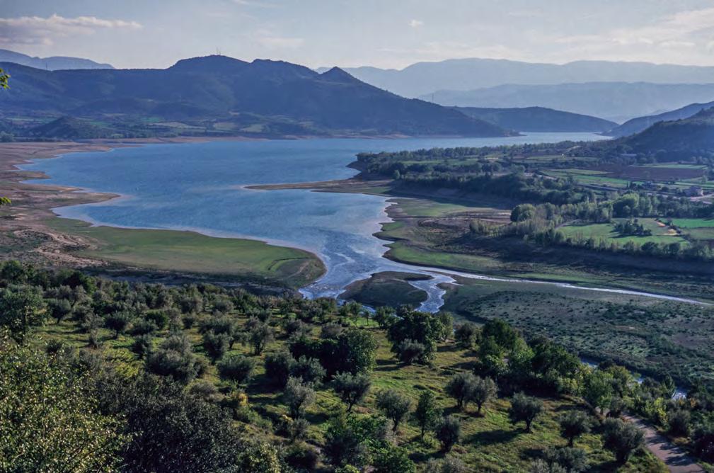
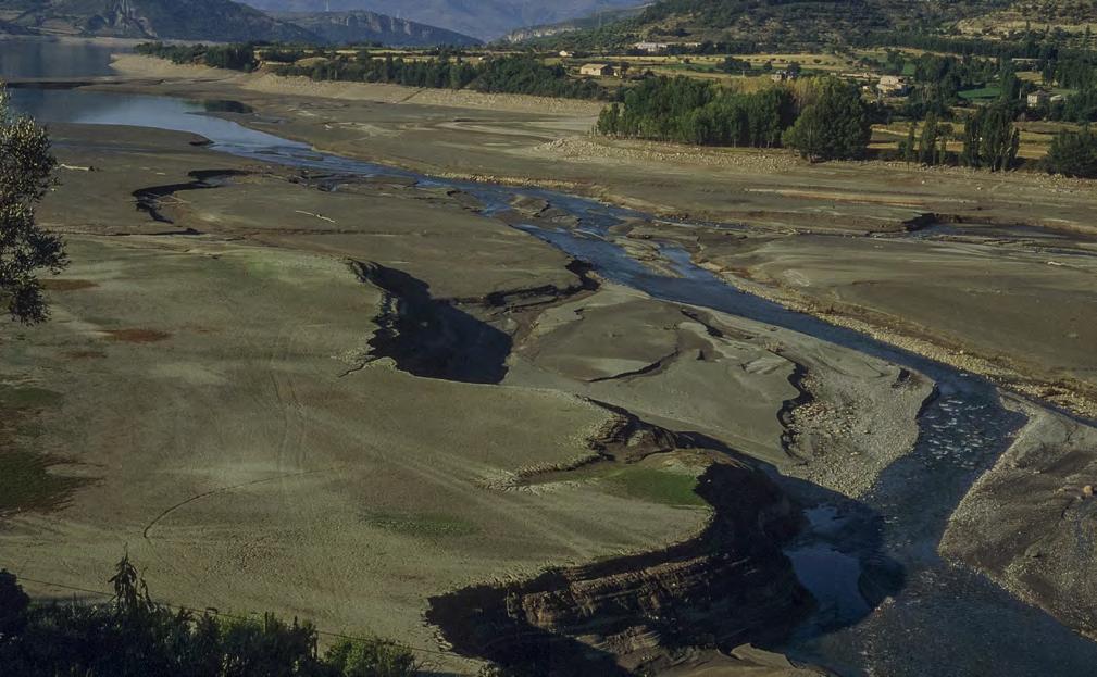
CHAPTER III TURBIDITE SYSTEMS: AN OUTCROP-BASED ANALYSIS 418
Fig. 481 - Simple examples of highstand and lowstand conditions in an artificial Lake (Lake San Antoni) near Tremp, Catalan Pyrenees. Note deep fluvial erosion (incised valleys) during low stand conditions.
A
B
HIGH STAND OF LAKE LEVEL
LOW STAND OF LAKE LEVEL
Three examples of the application of sequence stratigraphic analysis of increasing detail are discussed below to emphasize the complexity of these problems. The examples deal with shallow-marine deposits where the approach is easier to follow.
Figure 483 shows a detailed stratigraphic cross-section depicting, on an almost bed-by-bed basis, the architecture of the Eocene Castigaleu Group in the Esera valley, south-central Pyrenees. The study area was mapped in detail (Figure 484) and the cross section extends over a distance of some 2.5 km. The unit is approximately 480m m thick and is predominantly made up of delta-front sandstones and prodeltaic mudstones with subordinate intercalations of foramol-type of carbonates in the middle portion of the succession. The entire succession has been subdivided into 16 elementary depositional sequences, some of which are certainly composite. Overall, the succession can be interpreted as the product of a transgressive-regressive cycle (very likely a 3rd order cycle) with incised valley
fills (EDSs 1, 2 and 3) at the base grading upward into progressively thinner sandstone bodies alternating with mudstones and increasingly thicker carbonate facies recording a period of substantial relative sea level rise (EDSs 4 through 6). A maximum transgressive period is probably recorded by EDSs 7 and 9. Above EDS 9, the trend becomes regressive, recording a period of late highstand or falling sea level. Though this trend is very clear from inspecting the cross section, putting precise boundaries between these stages of evolution is, nonetheless, still somewhat subjective.
The component facies of this delta-front succession form a very complex spectrum of sediments including lenticular and relatively thick mouth-bar deposits, channel-exit cross-bedded units formed seaward of river mouths and characterized by a broadly lenticular geometry, thin sandstone lobes, prodeltaic mudstones and carbonates. Tidal action with reworking of river-born sediment occurs in most part of the succession, particularly in its proximal and shallower-water portion.
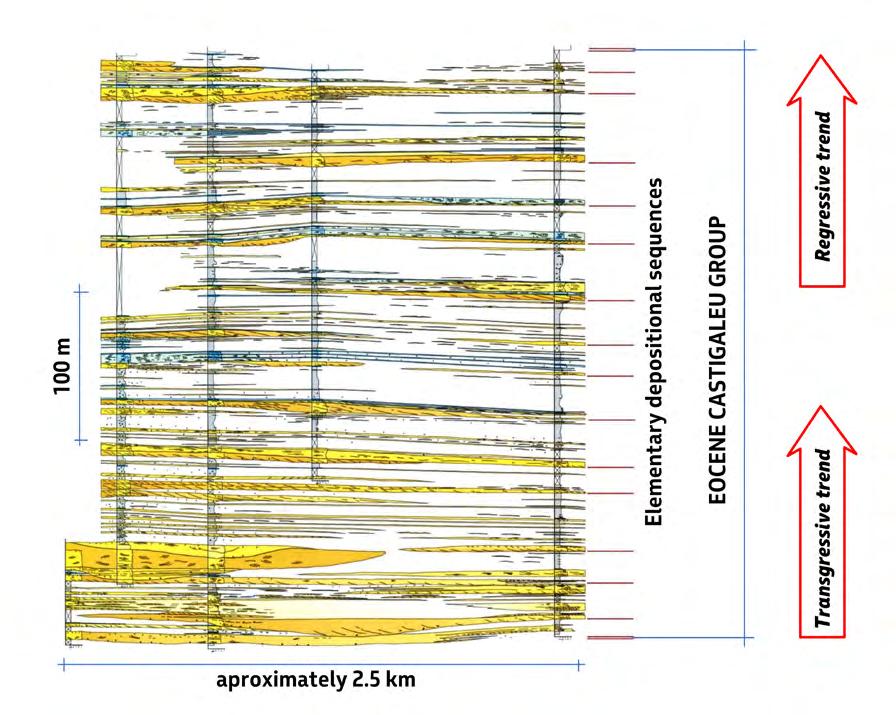
CHAPTER III TURBIDITE SYSTEMS: AN OUTCROP-BASED ANALYSIS 419
Fig. 483 - Detailed stratigraphic cross section of delta-front deposits. From Marco Figoni and Emiliano Mutti (1993, unpublished data).
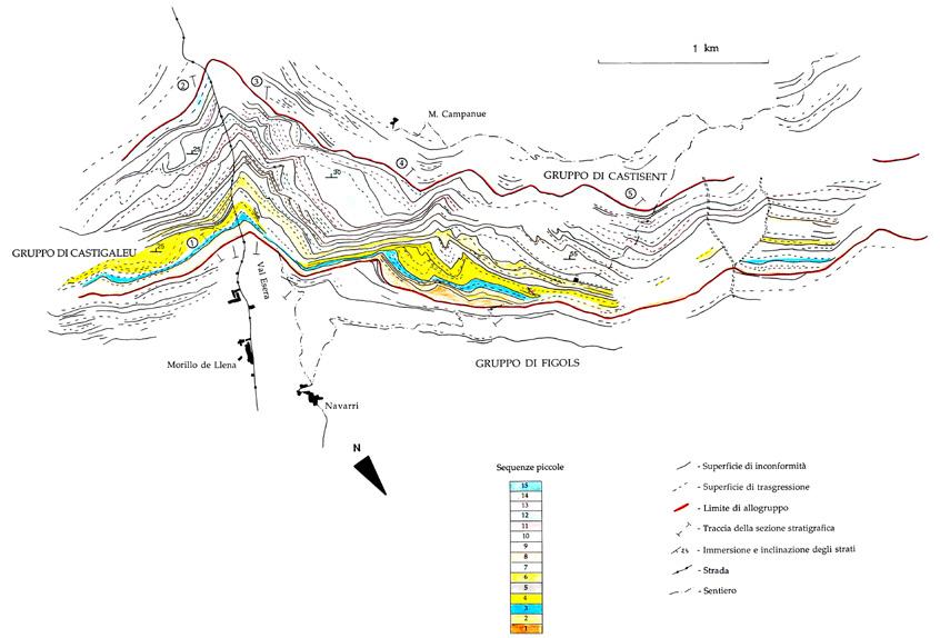
As the reader can see from the cross-section, the more you go into detailed observations, the more difficult and subjective is becoming the interpretation. The cross-section has been walked-out for many weeks by Marco Figoni (an excellent former student of mines) and me and it is basically highly reliable. Nonetheless, the reader will realize how difficult are the correlations in shallow-marine deposits undergoing facies changes over short distance and how much time would be required to extend this kind of work to a regional scale. It will also be noted that settings like this would be difficult to reconstruct in the subsurface (field scale) based on well logs and seismic. As summarized in the conceptual diagram of Figure 485, the problem resides in the lateral extent of the sandstone bodies and their component beds and in the lithologic contrast that allows for the recognition of their boundaries. These boundaries become gradually unrecognisable both laterally and in a basinward direction simply because sandstones thin and eventually shale out.
Summing up, the cross section of Figure 483 is an example of how far one could go by using the same approach at a regional scale and how much information
one could collect on facies, facies associations and sandstone body geometry. A project like this would take years of field work and talented, highly motivated people. We are all aware that these projects exist only in the dreamland.
Figure 486 describes an exposure that I like very much and where I took hundreds of students to show them my way to quickly look at the rocks and try to get some answer from them. The outcrop is located near Tremp, in the beautiful Catalan Pyrenees, and exposes the uppermost stratigraphic portion of the upper Cretaceous Aren Sandstone in the southern limb of the Tremp syncline. The Aren Sandstone is one of the most interesting units of the south-central Pyrenees being characterized by a very complex stratigraphic succession deposited during a regional phase of tectonic inversion (see a brief account in Mutti, 2019). It is therefore an example of syn-tectonic sedimentation. The portion of the unit that is exposed at this locality records the final phases of a regional regression that progressively shifted the shoreline toward the north. The above information gives you the general context within which we should frame our observations.
CHAPTER III TURBIDITE SYSTEMS: AN OUTCROP-BASED ANALYSIS 420
Fig. 484 - Detailed map of the elementary depositional sequences comprising the Eocene Castigaleu group in a sector of the Esera Valley (south-central Pyrenees) (from Marco Figoni, unpublished MS thesis, 1993).
The section shown in Figure 486 is approximately 50m thick and well exposed; it overlies flood-generated sandstone shelfal lobes and beachrock deposits (not shown) and is abruptly overlain by a lacustrine succession. The local succession can be schematically subdivided into 10 units, each of which is a facies with well-defined characteristics; these facies can be grouped into three small-scale depositional sequences bounded by unconformity surfaces (red lines in Figure 486) recording periods of relative lowstand and subaerial exposure. The surfaces became transgressive surfaces when sea level started rising again. The lower boundary of the lowermost sequence is not shown.
Basically, the component sandstone facies of the local section indicate that deposition was the result of wave and tidal action in very shallow environments, which are
highly sensitive to small-scale sea level variations. The facies association includes oyster-rich finer-grained and bioturbated deposits and lacustrine limestones. As shown in the scheme of Figure 487, the only recent environment where these facies can coexist is a barrier island, a flat coastal landform where waves build strips of sand (barrier island s.s.) parallel to the mainland coast with intervening lagoons, marshes and coastal lakes. Tidal inlets, cut into the barrier, provide a path to allow circulation of seawater in the lagoons. Inlet closure forces the lagoon to become a coastal lake. Tidal currents typically form small tidal deltas adjacent to the inlet: flood tidal deltas form in the lagoon and are easily preserved; ebb tidal deltas form in the shoreface zone and are rarely preserved, being usually reworked by wave action. Washover deposits, formed by storms, are generally common immediately behind the barrier.
CHAPTER III TURBIDITE SYSTEMS: AN OUTCROP-BASED ANALYSIS 421
Fig. 485 - Different expressions of EDS’s as a result of their different location along the depositional profile (modified after Mutti, 1989).
Shalying out
C B A
LANDWARD
Expression of EDS at different locations along the depositional profile
Thinning BASINWARD
Incised valley fill
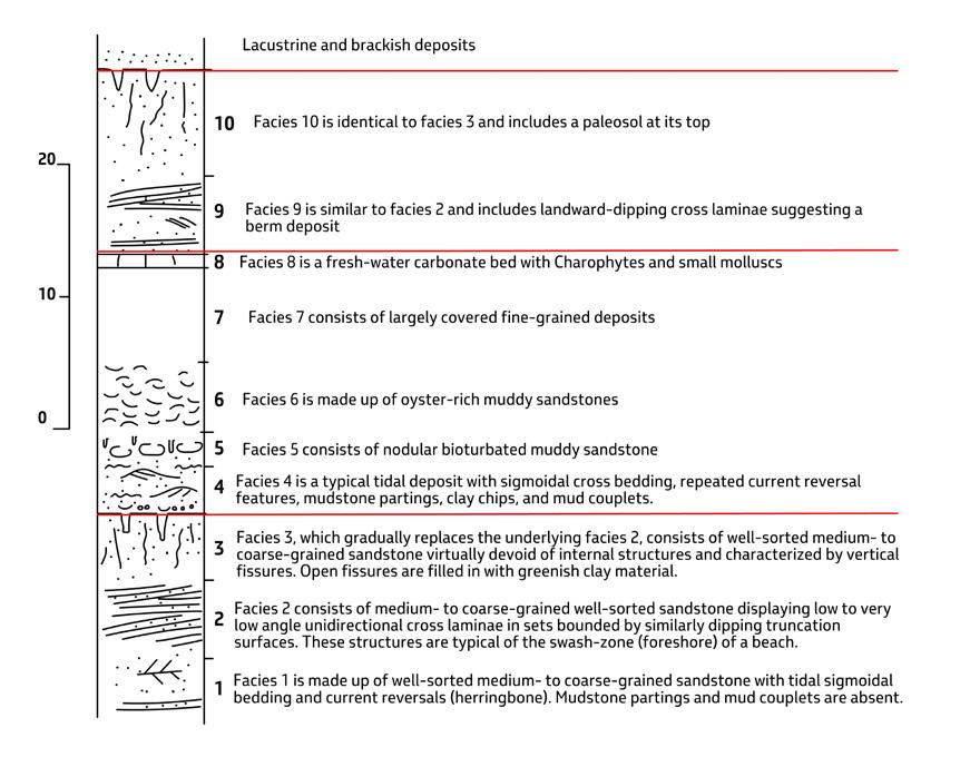
Based on the above model, the section of Figure 486 can be easily interpreted as a typical facies association of a barrier island system. The tidal facies of Unit 1 is interpreted as a remnant of a tidal inlet because of its close association with the beach-face deposits of unit 2 (Figure 488). The lack of mudstone partings, typical of tidal sediments, can be explained by the high energy of the environment undergoing wave action at the same time. Units 2 and 9 are interpreted as the foreshore and backshore deposit of a barrier island. The low-angle cross laminae of the foreshore indicate that the open sea was to the north (left in Figure 488). Unit 4 is interpreted as a flood tidal delta (Figure 489), grading upward into bioturbated (Unit 5) and eventually lagoonal deposits with oysters (Unit 6). Unit 8 is a thin and fossiliferous lacustrine carbonate bed. Units 3 and 10 are more difficult to interpret if not viewed within the framework of relative sea level variations. Basically, these units do not preserve their original sedimentary structures and
are instead characterized by diffuse vertical fissures some of which open upward being filled in by greenish clay material. The interpretation suggested here is that original beach or aeolian deposits of a barrier island underwent early cementation and subsequent karstification during subaerial exposure, that is during and after a relative fall of sea level. Unit 3 is sharply overlain by a tidal ravinemet surface with small pebbles and oyster fragments (Figure 489). Unit 10, which also contains a caliche at its top, is similarly sharply overlain by a transgressive lacustrine sandstone (Figure 490). The sketch of Figure 491 shows the ups and downs of selevel as inferred from the local succession.
Admittedly, the above interpretation was made easier by the fact that a few years before I have had to opportunity to take a look of the Sanaga delta, Cameroonjust a modern copy of the Aren Sandstone examined in this section.
CHAPTER III TURBIDITE SYSTEMS: AN OUTCROP-BASED ANALYSIS 422
Fig. 486 - Facies and main surfaces of the Aren Sandstone in the Llimiana section, near Tremp, south-central Pyrenees.
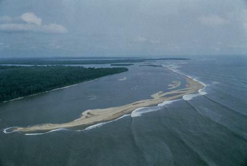

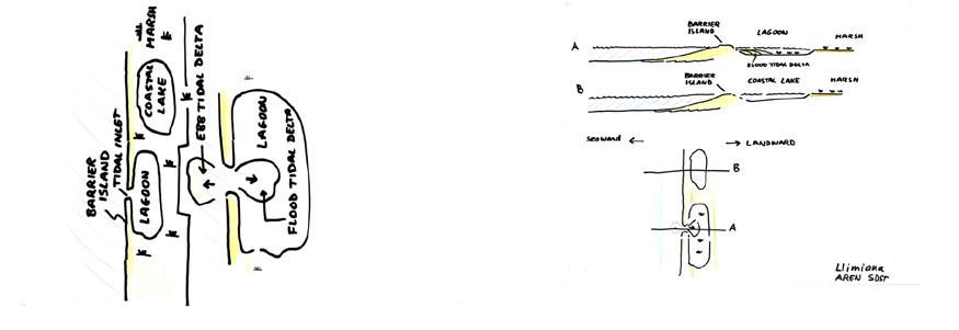
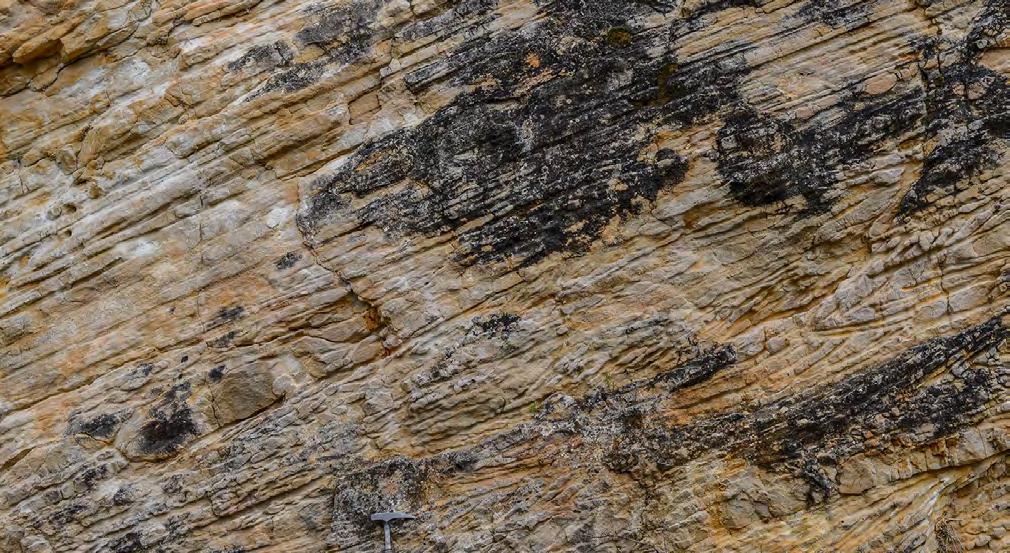
Foreshore
CHAPTER III TURBIDITE SYSTEMS: AN OUTCROP-BASED ANALYSIS 423
B
A
Sanaga delta (Cameroon)
Fig. 487 - A. Example of barrier islands in a modern delta (Sanaga delta, Cameroon). BI: barrier island; L: lagoon; TI: tidal inlet: CL: coastal lake; B. Depositional model.
Fig. 488 - Tidal inlet sandstones, with sigmoidal bedding and current reversals (herring-bone cross stratification), abruptly overlain by low-angle cross laminae of a foreshore environment (cross laminae gently dip to left, indicating seaward direction).
Tidal inlet
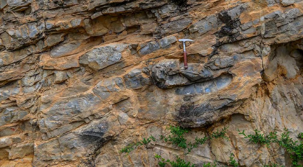
Tidal ravinement surface with small pebbles and oyster fragments
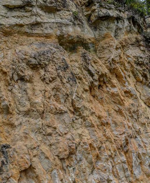
Caliche
Lacustrine transgression
Fissured beach deposits that underwent emersion and subaerial exposure
Open fissure filled withclay material
CHAPTER III TURBIDITE SYSTEMS: AN OUTCROP-BASED ANALYSIS 424
Fig. 489 - Tidal sandstones, with sigmoidal bedding, mud couplets and mudstone partings, resting on an unconformity surface through an irregular erosion referred to as “tidal ravinement surface. Small pebbles and oyster fragments occur along the surface. The tidal sandstones are interpreted as a flood-tidal delta formed in a lagoon.
FLOOD TIDAL DELTA
Fig. 490 - Coastal lake deposits transgressive upon an unconformity surface.
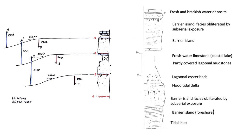
The final example is shown in Figure 492 describing a sandstone lithofacies of the upper Cretaceous Aren Sandstone near Orcau, south-central Pyrenees. The local Aren succession crops out in the southern limb of the San Corneli anticline, a feature that was growing during sedimentation (see Mutti, 2019, for more details). The sandstone lithofacies considered is well expressed in the landscape by a 10-15 meters thick, relief-forming feature that can be easily traced in the field and aerial photographs. The unit rests on an angular unconformity following a phase of uplift of the anticline. Tracing of the unit and careful facies analysis allow for the recognition of an unexpectedly complex setting that can be observed over a distance of less than 1000 m. After deposition, a bioclastic bar (left in Figure 492 A) underwent uplift, subaerial exposure and early cementation followed by erosion and subsequent sedimentation of tide-dominated sandstone facies (possibly a small estuarine element) in turn eroded by flood-dominated facies (sandstone lobes) transitionally capped by mudstones. Large blocks of the lithified, original bioclastic bar are found at the base of the sandstone lobes suggesting erosion from a nearby cliff along which the bar was exposed, All the story is recorded in a relief-forming feature that appears as an almost perfectly tabular body from distance and occurred in a relatively very short period of time, probably that involved in
the deposition of an elementary depositional sequence. The interpretation of settings of this type, showing the structural control on sedimentation at such temporal scale, certainly requires exceptionally good exposures. A further and substantial uplift of the San Corneli anticline led to the subsequent gravitational collapse of the entire succession, shown by the large erosional unconformity in the right part of Figure 492 A.
If you look carefully at Figure 492 B, an additional problem arises. Forgetting the bioclastic bar discussed above, which rests above the unconformity surface indicated by the red arrow, the local succession of the Aren Sandstone would seem a perfect example of a seismic-scale depositionlal sequence with a lowstand delta at its base (a in Figure 492 B), overlain by transgressive and early high-stand, mudstone-dominated deposits (b in Figure 492 B), in turn capped by late highstand or falling-stage sandstones and mudstones (2 in Figure 492 B). Were this the case, the local Aren setting would indicate structural deformation interrupting a cycle of relative sea level variation during its high-stand stage and the setting discussed above (Figure 492 A) would simply be a late and short-lived pulse of the same deformation. The syntectonic sedimentation of the Aren Sandstone still remains an open problem.
CHAPTER III TURBIDITE SYSTEMS: AN OUTCROP-BASED ANALYSIS 425
A B
Fig. 491 - Sketch showing the interpretation of the section in terms of environments and sequence-stratigraphy. Red lines show sequence boundaries. Each surface is underlain by sediments that underwent subaerial exposure after deposition and overlain by transgressive deposits following a rise of baselevel. Rises and falls of baselevel are schematically shown on the left.
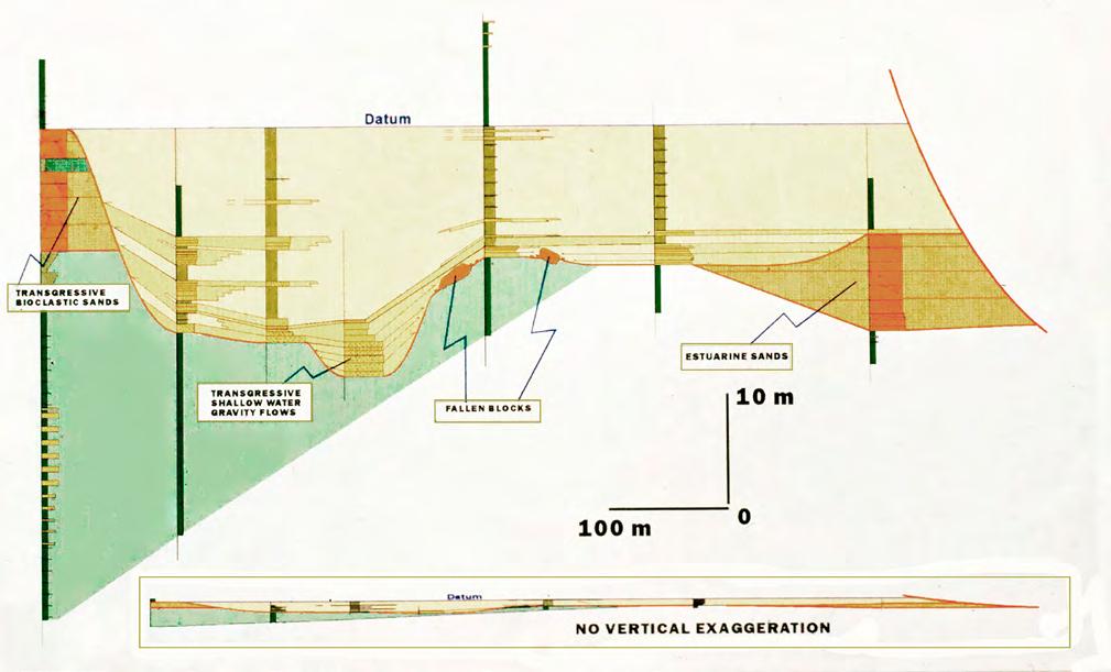
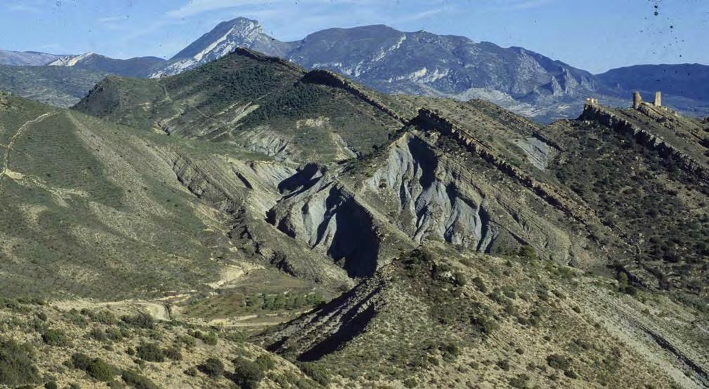
CHAPTER III TURBIDITE SYSTEMS: AN OUTCROP-BASED ANALYSIS 426
A B
Fig. 492 - Example of tectonic control at the scale of an elementary depositional sequence. Upper Cretaceous Aren Sandstone, near Orcau, south-central Pyrenees (see text for explanation) (from Mutti et al. 1994). A. Stratigraphic cross-section of a small sequence within the Orcau Sequence (from Mutti et al. 1994). B. Aren Sandstone near Orcau. 1: Lower large-scale composite depositional sequence; 1.a: Tidedominated lowstand delta; 1.b: Transgressive mudstones; White arrow: Maximum flooding surface. Conceptually, this surface should be somewhat higher in the succession, but has no physical expression there. 2: Upper large-scale composite depositional sequence made up of transgressive delta-front sandstone lobes. Red arrow: sandstone lithofacies shown in A and resting on the sequence boundary.
1
1. a
2
1. b
The examples discussed above clearly document how a sequence stratigraphic approach is fundamental in facies analysis and can be extremely useful in interpreting local settings at various scales. The approach permits, in most cases, to identify and interpret elementary depositional sequences and small-scale composite depositional sequences. In tectonically active basins, assembling these units into larger-scale sequences may however become difficult and subjective because of the tectonic control on sedimentation. Probably, the beautiful sequences depicted by seismic from many divergent continental margins and showing the ordered suite of lowstand, transgressive, highstand and falling-stage systems tracts have only a limited expression in tectonically active basins. Structural deformation may interrupt or attenuate, anywhere and anytime, this ordered pattern and superimpose on it an additional accommodation cyclicity mainly produced by alternating periods of orogenic uplift, exhumation of deep-seated tectonic units, and denudation. Climate is the main factor controlling sediment flux to the sea through forestepping-backstepping cycles developed at different physical and temporal scales (see Mutti et al., 1996, for an extensive discussion).
III – FLUVIAL FLOODS AND TURBIDITY CURRENTS
Turbidites and flood-dominated alluvial and fluvio-deltaic deposits share many characteristics in terms of facies, processes, sand-body geometry and stacking patterns. Many concepts developed for the interpretation of turbidite sedimentation easily apply to flood-dominated sediments. Both kinds of sedimentation take place through sediment gravity flows originated from the sudden formation of sediment-water mixtures that accelerate on sub-aerial or sub-aqueous slopes, increase their density through bed erosion and move across lower gradient regions of the depositional profile. The flows will gradually decelerate for friction and partial deposition until they will eventually deposit their load in their main final depositional zones. The general process is essentially the same in an alluvial fan and in its terminal flood basin, in a flood-dominated river entering a sea or a lake and forming sandstone lobes in its delta-front region, or in a large submarine fan and its adjacent basin plain. This process is however complicated in most cases by a great number of both intrinsic and extrinsic factors that make the final depositional system and its component elements and facies a virtually unique feature that should be analysed on a case-by-case basis. This is one of the good reasons geologists are still useful.
Having said this, it is tempting to speculate in which way these different kinds of depositional systems can be linked together to produce the final sedimentation in deep-water. The process can take place through progressive sediment transfer in a seaward direction from transient parking zones until high rates of sedimentation on the shelf and the slope promote instability processes and the formation of turbidity currents. This model is widely accepted for large rivers of divergent margins, as for instance the Mississippi. In such cases, large amounts of sediment are trapped in extensive alluvial plains during flood times and in meandering fluvial channels, acting at the same time as transfer and depositional zones.
The problem is quite different if orogenic belt basins are considered. As mentioned in previous sections, high-elevation drainage basins, high-gradient transfer zones, proximity to the shoreline and lack of extensive alluvial plains favor sediment flux to the sea mainly through floods (Milliman and Syvitski, 1992) and related hyperpycnal flows (Mulder and Syvitski, 1995). This is the domain of the small and medium size “dirty” rivers that are so different, as to size and regime, from the large, mature rivers entering the oceans in divergent continental margins. As documented in previous sections, ancient river systems of orogenic belt basins are dominated by facies and facies associations indicating deposition by bypassing and powerful flows that are necessary to explain the origin of hyperpycnal flows that entered seawater to deposit delta-front sandstone lobes or kept moving farther into deeper water to deposit turbidite sandstones.
At this point, there seems to be little doubt that fluvio-deltaic systems of orogenic belt basins are primarily built up by rivers in flood and related hyperpycnal flows and that the latter are not only able to transport sediment in suspension but can also produce composite types of flow where inertia-driven carpets can move pebbles and coarse sand. This is apparently the only way to explain the abundance of conglomerates and pebbly sandstones in deep-water basins.
The modern turbidite sedimentation in the fjords of British Colombia and its relation to seasonal floods add a fundamental key to a better understanding of the problem (see Chapter II). Here, deltas form during periods of low fluvial discharge, but their sediments are removed by strong seasonal floods and flushed into adjacent deep water being accelerated along steep depositional slopes. Chutes and gravel bars, formed by passing sediment gravity flows, pave the sea floor at the upcurrent end of turbidite channels and lobes devel-
CHAPTER III TURBIDITE SYSTEMS: AN OUTCROP-BASED ANALYSIS 427
oped in fjord inlets. A combination of dense river underflows and related sediment failures evolving into turbidity currents seems the best triggering mechanisms for producing turbidite sand accumulations in this kind of basins. A powerful dense underflow can certainly trigger liquefaction and remobilization of coarse-grained sediment accumulated at river mouth during periods of low fluvial discharge. The example of the Bute Inlet system described in great detail by Zeng et al. (1991) is possibly the best modern analogue for understanding some ancient sand-rich turbidites of orogenic belt basins. The transition from river underflows to turbidity currents will remain difficult to observe and document, since the turbidity current will form after substantial bed erosion and acceleration leaving only limited record (erosion, gravel bars) of its transit.
IV – A MINOR BUT IMPORTANT REFINEMENT OF TURBIDITE FACIES SCHEMES
Turbidites and plumites are the basic components of deep-water systems of orogenic belt basin fills. A better understanding of these systems largely depends on framing these two types of deposits within the more general context of flood-related sedimentation. To this purpose, plumites form an ideal link between fluvial and turbidite deposition.
The scheme of Figure 493 shows the three basic types of river outflow: (1) a dense gravelly or sandy flow that enters seawater and essentially keeps moving seaward as a bottom-riding, inertia-driven and strongly hyperpycnal flow; (2) a sediment-laden, turbulent streamflow that seaward of river mouths evolves into an inversely buoyant plunging plume; and (3) a turbulent streamflow with low sediment-concentration that propagate seaward as a hypopycnal plume. Depending upon basin configuration, the first two types of flow deposit their sediment load in nearshore and shelfal regions as sandstone lobes and their distal muddier equivalents, or directly move to deepwater, increase their density through bed erosion (ignition) and become hyperpycnal turbidity currents or turbidity currents tout court. The third type of flow, the surface plume, is common to both shallow and deepwater settings.
Most individual floods behave in a similar way, that is they are transitional types of flow between the two end members represented by dense flows and turbulent, sediment-laden stream flows. In other words, most floods enter seawater as mixtures of bed load and suspended load. Entering seawater, a flood of this kind will basically split into three parts (Figure 494): (1) a dense basal flow moving along the bed; (2) a finer-grained
turbulent flow evolving into a plunging plume; and (3) a dilute hypopycnal flow floating on seawater and propagating as long as fed by the river.
Along with many other factors, the relative proportions of the grain-size populations (gravel, coarse sand, fine sand and coarse silt, and mud) within the flow strongly control the final characteristics of the resulting turbidite bed and more generally the facies characteristics of an entire system. Additional sediment will be added by bed erosion, including remobilisation of previous channel-exit sediment deposited during periods of low fluvial discharge. The resulting great variability of flood-related turbidite systems, contrasts dramatically with the simple and widespread blanketing of plumites, which are only composed of suspended finegrained sediment undergoing fractioning through settling. The great facies variability of turbidite systems, with which we are all familiar, is therefore the result of the similar variability of the proportions of the different grain-size populations in the parental fluvial flows.
IV.1 - THE IMPORTANCE OF COHERENCE IN DENSE FLOW EVOLUTION
An important controlling factor on facies types is related to the amount of clay contained in the dense flows since it inhibits the dissipation of excess pore pressure, thus increasing the runout distance of the flow. As suggested by Marr et al. (2001) in their paper on debris flows “coherence”, relatively high proportions of clay increase the ability of a dense flow (their “debris flow”) to resist being eroded by dynamic stresses during its motion. Stated in simple words, this means that a dense flow with a poor clay content, breaks up during its motion to become a turbulent flow, whilst, with a high clay content, the flow keeps moving maintaining (though reducing it with distance) its internal strength and most of its excess pore pressure.
The assumption that flow strength and excess pore pressure have an important role in the runout distance of dense flows had already been made by Ravenne and Beghin (1983) and Norem et al. (1990) on the basis of flume experiments. Based on field data, Mutti et al. (1999) substantiated the same assumption by introducing their bipartite subdivision of turbidity currents into a basal, dense granular flow, driven by inertia forces and under conditions of excess pore pressure, and an overlying turbulent flow. Shanmugam (1996) went even farther, suggesting that most structureless sandstone divisions of turbidite successions should actually be considered as the deposit of coherent “sandy debris flows”, not turbidity currents.
CHAPTER III TURBIDITE SYSTEMS: AN OUTCROP-BASED ANALYSIS 428
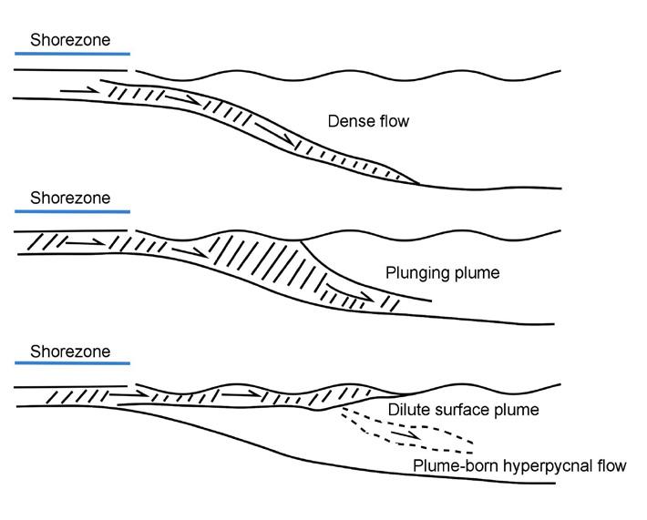
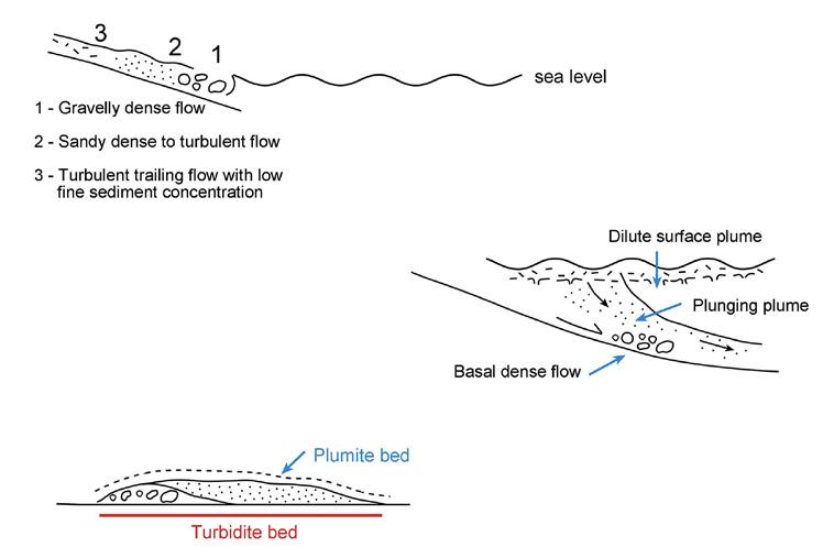
CHAPTER III TURBIDITE SYSTEMS: AN OUTCROP-BASED ANALYSIS 429
Fig. 493 - The three basic types or river outflows. A. dense flow; B. plunging plume; C. dilute, buoyant plume. After Mutti (2019 a).
B A C
Fig. 494 - River outflow with mixed grain-size populations giving way to a turbidite bed and an associated plumite bed. For different proportions of grain-size populations the resulting turbidite bed may greatly vary in terms of facies. After Mutti (2019 a).
Coherence of dense flows and its variability may help to better understand a basic point of the turbidite facies scheme introduced in Chapter II and, for the reader’s convenience, reproduced here as Figure 495). As shown in the scheme of Figure 496, the downcurrent evolution of strongly coherent and poorly coherent flows is substantially different. Strongly coherent flows may travel over considerable distance, though progressively loosing their coarser grained fraction for settling, maintaining sufficient strength and excess pore pressure to resist being broken by turbulence; conversely, weakly coherent flows break down soon and the sandy portion is resuspended by turbulence. The amount of sand that is suspended depends on the original textural composition of the flow and the strength of the turbulent flow. Accordingly, deposition from these flows is different. In the first case, deposition will take place through freezing and result in an essentially structureless division (Figure 497 A); in the second case, sedimentation will occur through aggrading laminae produced by a traction-plus-fallout mechanism (Figure 497 B). Field evidence indicates that both types of division are in places overlain by subcritical megaripples (see Chapter II), suggesting that both divisions are supercritical features. The two divisions have essentially the same grain size but are substantially different as to their origin. As we have learnt from many other examples, also these pro-
cesses must be intergradational, thus leaving ample room from transitional facies types.
Based on the above considerations (see also Mutti, 2019 a), I would be tempted to slightly modify the turbidite facies scheme of Figure 495 by adding a new facies type (F3a) that is essentially the finer grained portion of Facies 2 in the old scheme. The refined facies scheme is shown in Figure 498.
At this point the reader may think that I went a little too far and became too specialized and I can understand his point. In my own defense, let me say that I spent so much time in my life trying to understand turbidite facies that I cannot resist attempting new possible ways. Anyhow, if the reader will be involved in the future in some research dealing with detailed facies analysis of turbidite systems, in outcrop or cores, he will realize how many structureless and laminated divisions of these sediments can be framed within the new scheme. The basic concept to retain is that dense flows tend to be eroded, during their motion, by the associate turbulent flows that gradually incorporate in their suspended load the grainsize populations of the dense flow compatible with turbulence intensity. The scheme and the example of Figure 499 may be useful to clarify the problem.
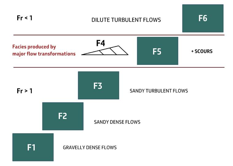
CHAPTER III TURBIDITE SYSTEMS: AN OUTCROP-BASED ANALYSIS 430
Fig. 495 - Rationale behind the subdivision of turbidite sediments into facies Groups (F1 through F6).
A B
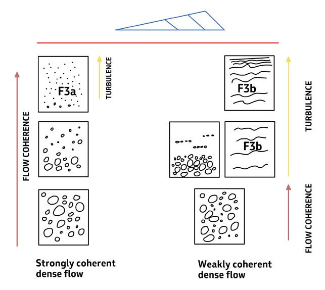
V – TURBIDITES AND CONTOURITES
Since the pioneering work of Hollister and Heezen (1967) in the North Atlantic, contour currents, generated by thermohaline circulation, have long be considered as an important process in shaping continental margins and depositing thin beds of well-sorted fine sands, termed contourites. As pointed out by Stow and Lovell (1979), the discovery of this process and its deposits could have been a potentially breakthrough contribution to sedimentary geology. This did not happen mainly because at that time sedimentologists were fascinated by turbidite sedimentation and, most importantly, contourites were and still are
difficult to recognize in outcrop. Turbidites were born from field observations in exposed orogenic belt basin fills (Migliorini, 1943, Kuenen and Migliorini, 1950), i.e., in relatively small basins unaffected by large-scale oceanic circulation (Mutti and Normark, 1987). Contourites are probably best developed in divergent margin settings or in large basins of convergent margins that are rarely exposed. Nonetheless ancient contourites must exist somewhere, in some exposed basin fill, and must have gone unnoticed or misinterpreted until now (see below). As far as we are concerned here, contourites and their problems are of marginal interest and therefore only briefly discussed hereafter.
CHAPTER III TURBIDITE SYSTEMS: AN OUTCROP-BASED ANALYSIS 431
Fig. 496 - A strongly coherent flow (A) has a rate of coherence loss that is less than its velocity and can thus attain long runout distances. Conversely, a weakly coherent dense flow (B) breaks up soon and its sand load is suspended in a supercritical turbulent flow. The amount of sand that goes in suspension depends on the original textural composition of the flow and the strength of the turbulent flow. Field evidence shows that the final products of both flows are capped by subcritical megaripples.
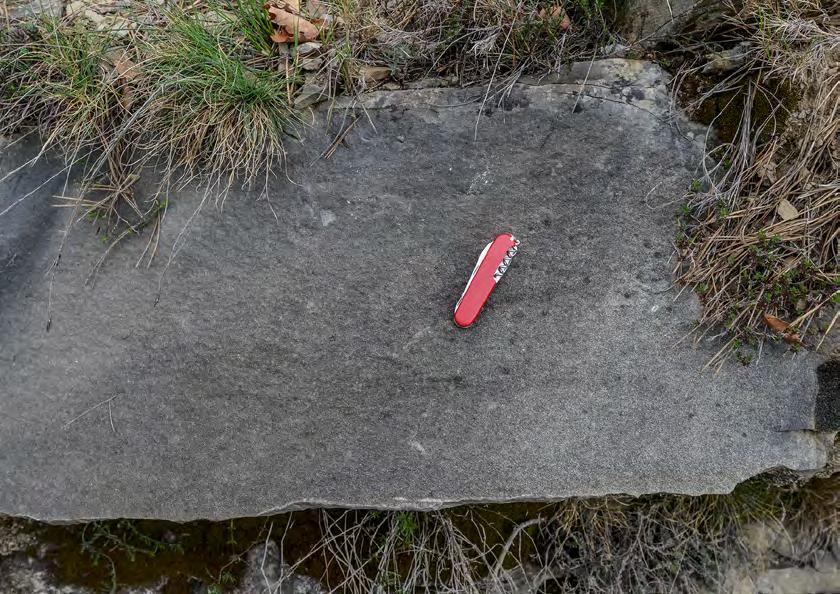
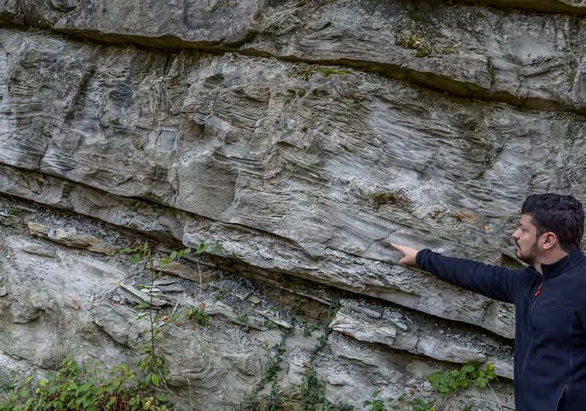
Structureless division made up of medium to fine sandstone and capped by a thin division of laminated sandstone.
Eocene
Hecho Group, south-central Pyrenees
Well-laminated basal division made up of medium to fine sandstone overlain by a thick division of climbing ripples.
Miocene
Laga
Formation, Apennines
CHAPTER III TURBIDITE SYSTEMS: AN OUTCROP-BASED ANALYSIS 432
A B
Fig. 497 - Both examples consist of medium to fine sandstone; the sediment is much better sorted In B.
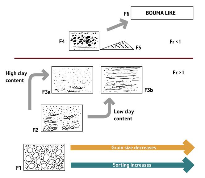
Bottom currents and contourites have received increasing interest from oceanographers, marine geologists and sedimentologists in recent years. It would be beyond the scope of this book to review all the literature dealing with this problem. The interested reader may find extensive reviews of the most pertinent literature in Rebesco et al. (2014) and Shanmugam (2017). If we consider as contourites simply a deposit with its specific facies characteristics and therefore recognizable in core and outcrop studies, the above reviews leave no doubt that much work remains to be done. Contour currents and their deposits are still viewed as an extremely complex problem involving oceanographic processes in surface, intermediate and deepwater masses (Figure 500) and having their origin in dense bottom currents, tides, eddies, deep-sea storms, internal waves and tsunamis (Rebesco et al., 2017). Though sandy contourites are increasingly reported from modern basins, there is still a general tendency to accept early models describing contourites mainly as fine-grained and bioturbated thin-bedded sandstones (e.g., Stow, 2002) (Figure 501).
Whatever their ultimate origin, deep-water sandy contourites, with excellent reservoir quality, can be recognized on the basis of core analysis and seismic data in the Brazilian offshore basins (Mutti and Carminatti, 2012; Mutti et al., 2014) and have been preliminary identified by Capella et al. (2017) in outcrop studies from the late Miocene Rifian Corridor, Morocco.
Bottom currents may interact with turbidite deposition giving way to mixed depositional systems. The interaction and the resulting types of system are schematically depicted in Figure 502 showing how turbidite sands can be eroded and displaced with time leading to contourite systems. The interaction can take place at the scale of an individual turbidity current that during its downslope motion can lose its fine-grained suspended load pirated by a bottom current flowing at a nearly right angle (Shanmugam et al., 1993) (Figure 503). A similar model has been used by Fonnesu et al. (2020) to explain the exceptional reservoir quality of axial turbidites in the Eocene Coral field, Mozambico (Figure 504). Seismic is clearly the only tool to approach these architectures.
CHAPTER III TURBIDITE SYSTEMS: AN OUTCROP-BASED ANALYSIS 433
Fig. 498 - Suggested new turbidite facies scheme emphasizing two different possible evolutions from a dense flow (F2). If sufficient coherence is maintained, the flow will still move as a dense flow producing a bed of structureless finer-grained division (F3a); conversely, if coherence is lost the flow will move as a supercritical turbulent flow that will produce a laminated bed. In the upper half of the scheme, F5 has been moved updip of F4 since mudstone clast erosion and deposition take place during a dense flow stage.
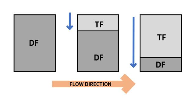
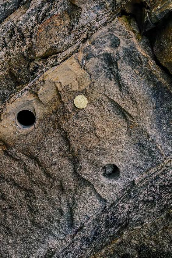
Tailflowdeposit
Bypass surface
Dense flow sediment reworked and laminated by turbulent flow (parallel laminae probably formed from near-bed suspension)
Structureless remnant of dense flow deposit
CHAPTER III TURBIDITE SYSTEMS: AN OUTCROP-BASED ANALYSIS 434
A
Fig. 499 - Suggested model of dense flow (DF) erosion (resuspension) from the overlying turbulent flow (TF). The example is from the Eocene Hecho Group, south-central Pyrenees.
B
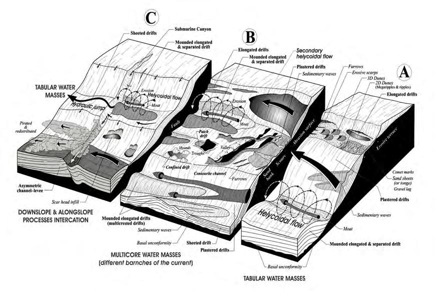
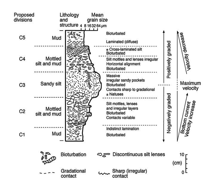
CHAPTER III TURBIDITE SYSTEMS: AN OUTCROP-BASED ANALYSIS 435
Fig. 500 - The complexity of water mass circulation, related bottom currents and associated laterally derived turbidity currents (after Stow et al., 2011).
Fig. 501 - The classic contourite facies model as suggested by Stow (2002) emphasizing the fine-grained nature of the deposit and its limited thickness.
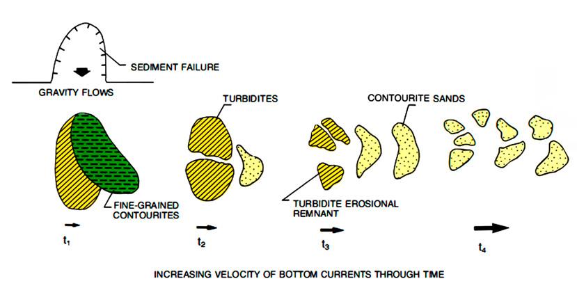
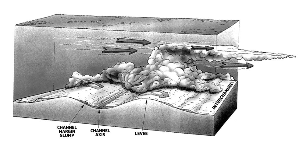
by permission of the AAPG whose permission is required for further use.
CHAPTER III TURBIDITE SYSTEMS: AN OUTCROP-BASED ANALYSIS 436
Fig. 502 - Idealized evolution of a mixed depositional system resulting from the interaction of turbidity currents and bottom currents (after Mutti, 1992).
Fig. 503 - The model suggested by Shanmugam (1993) explaining the relationships between downslope flowing turbidity currents and along slope flowing bottom currents. Fines of the turbidity current are pirated by the bottom current. From Shanmugam, G., T. D. Spalding, and D. H. Rofheart, 1993; AAPG Bulletin, v. 77, no. 7, p. 1241-1259. Reprinted
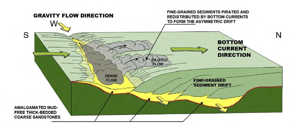
By integrating seismic data and extensive core analysis in the offshore Brazilian basins, Mutti and Carminatti (2012) and Mutti et al. (2014) have documented that sandy contourite systems, formed as seismically well-defined sand waves (Figure 505) away from their feeder turbidite sand accumulations, are characterized by very distinctive seismic signature and facies types. These authors were able to recognize (1) remnants of coarse-grained turbidite facies reworked in situ by tidal-driven bottom currents and (2) fine-grained and extremely well-sorted contourite facies that, from progressively decreasing strength of the flow, were framed in a preliminary facies scheme (Figures 506508). Though from sparse core observations, some alternations of coarse-grained and virtually mud-free turbidites and fine-grained contourites (including biogenic marls) suggest a small-scale cyclicity as shown in Figure 509. The pattern seems to indicate that after an initial phase of turbidite deposition, with the fines washed out by bottom currents, contourite sedimentation takes over and decreases with time in a stepwise fashion until turbidite deposition is resumed. It will be noted that this pattern strongly resembles that of fluvio-deltaic sedimentation in incised valleys (see
above), which is replaced by transgressive tidal-controlled sedimentation during sea level rise. Probably also in deepwater settings sequence stratigraphy might face interesting and unexpected applications.
From a simple and practical standpoint, though keeping in mind the complexity of the problem, contourites (herein intended as the deposit of bottom currents regardless of their origin) can be recognized essentially on the basis of negative criteria. Stated in other words, if we know that we are dealing with a relatively deep water succession and observe cores or outcrops showing sedimentary structures inconsistent with such water depth we should start to be alerted. By the way, this was how we discovered bottom-current deposits in the Campos basin back in the in the late 70’s (Mutti et al., 1979). We found that most turbidite sandstone beds had eroded tops and were overlain by thin-bedded and highly bioturbated finer-grained deposits resting upon the erosional surfaces. We thus concluded that original turbidity current deposits had ben eroded by relatively weak bottom currents, taking away fines and thus improving their reservoir quality (Figure 510).
CHAPTER III TURBIDITE SYSTEMS: AN OUTCROP-BASED ANALYSIS 437
Fig. 504 - Model explaining the axial mud-free turbidite sandstones of the Eocene Coral field, Mozambique, and the association of contourite drifts and turbidites. After Fonnesu et al. (2020) (originally after Fonnesu 2013).
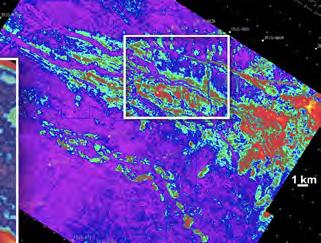
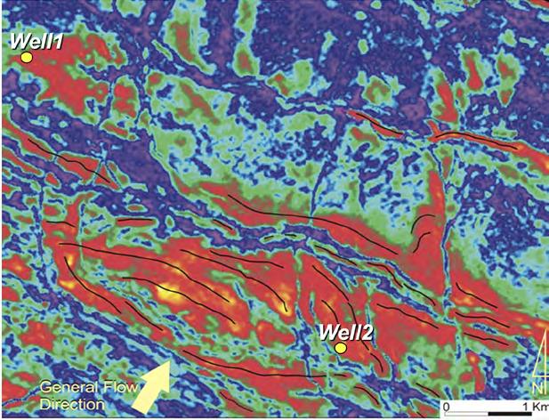
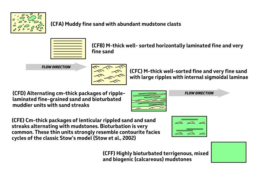
CHAPTER III TURBIDITE SYSTEMS: AN OUTCROP-BASED ANALYSIS 438
Fig. 505 - Sand wave field produced by bottom currents. After Mutti and Carminatti (2012).
Fig. 506 - Preliminary Contourite Facies Tract Inferred from Core Observations (after Mutti and Carminatti, 2012).
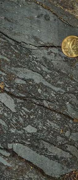
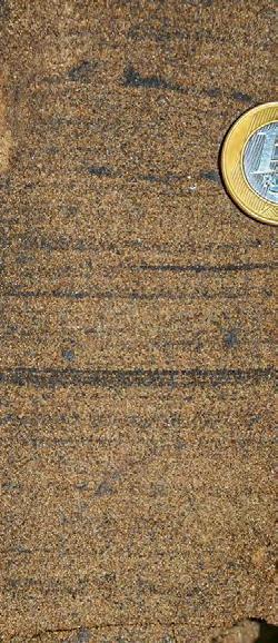
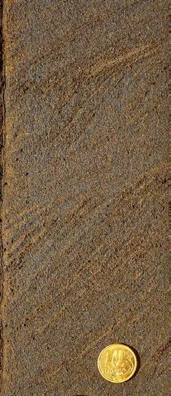
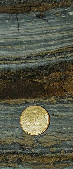
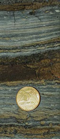

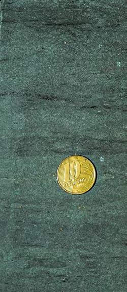
CHAPTER III
SYSTEMS:
439
TURBIDITE
AN OUTCROP-BASED ANALYSIS
Fig. 507 - Contourite Facies Tract (after Mutti and Carminatti, 2012). CFF
CFA CFD CFD
CFB CFE CFC
Fig. 508 - Contourite facies tract (after Mutti and Carminatti, 2012).
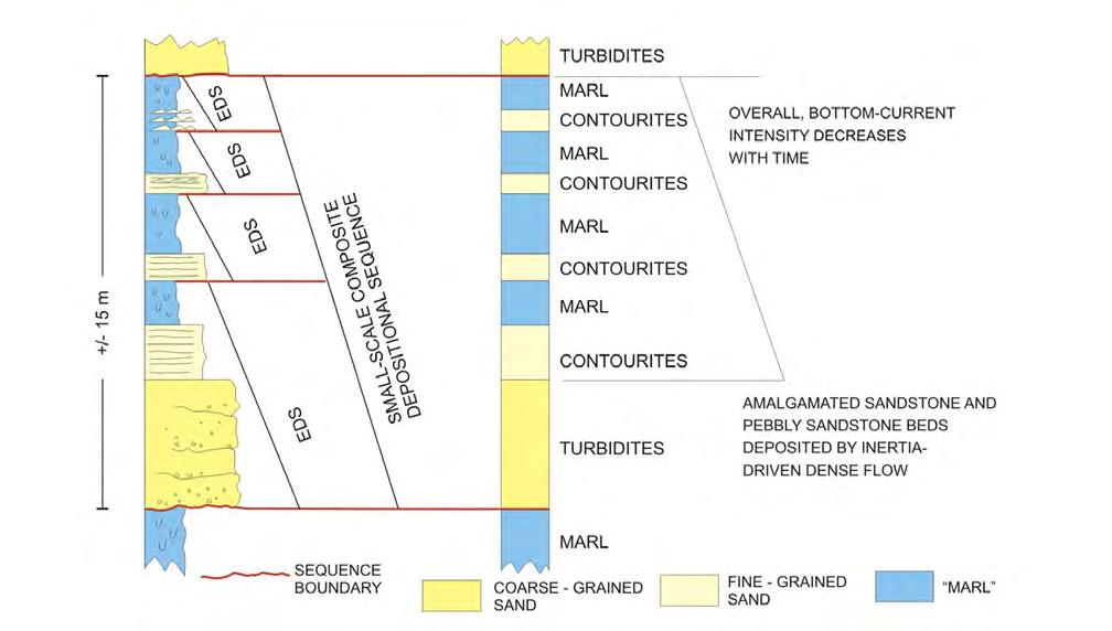
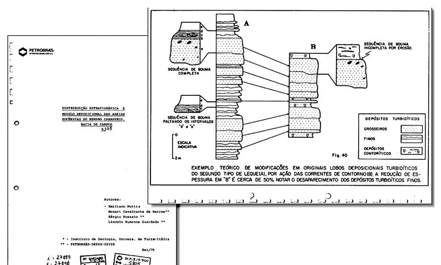
CHAPTER III TURBIDITE SYSTEMS: AN OUTCROP-BASED ANALYSIS 440
Fig. 509 - Association of coarse-grained, mud-free and thick-bedded turbidites with fine-grained contourites (including biogenic marls). The small-scale cyclic stacking pattern suggests that turbidites record high-energy episodic events in an environment dominated by bottom currents and their cyclic sedimentation through time. Note the attempt to introduce the concept of elementary depositional sequence also in these basically unknown depositional settings. See text for more details (Mutti, unpublished data).
Fig. 510 - A first attempt to recognize turbidites reworked by bottom currents based on core analysis.
Contourites are certainly one of the future targets of hydrocarbon exploration in deep and ultra-deep waters and, as such, they are and will be the subject of extensive research especially by industry. Field analogues are extremely rare and most of them are still matter of controversies. Based on my experience, I would suggest that part of the Permian Brushy Canyon Formation, Delaware basin, Texas, would be an interesting example for detailed field analyses. The unit, generally thought to be a typical turbidite system (see Beaubouef et al., 1999: Gardner et al., 2003, with references therein), contains peculiar deposits that, based on careful analysis, were interpreted as bottom-current (saline density currents) deposits by Harms (1988). I visited some of the outcrops and should admit that the facies observed are the only example I have seen until now that would fit what a bottom-current deposit should be. For sure, these facies are not turbidites, though being associated with turbidites and thus being a deepwater deposit. These sediments certainly need a critical re-examination. Examples of these sediments are shown in Figure 511.
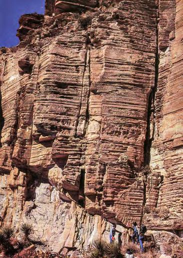
VI – OROGENIC BELT AND CONTINENTAL-MARGIN BASINS
As noted by Mutti and Normark (1987), ancient orogenic belt turbidites used to understand modern and buried turbidites of continental margins and viceversa may be a dangerous exercise without a critical appreciation of their differences. Classical turbidites of orogenic belt basins formed in relatively narrow and elongate troughs bounded by tectonically active margins and with very limited development of shelves. As documented by all the classical flysch units of the circum-Mediterranean orogenic belts, these troughs were never reached by substantial oceanic water mass circulation and particularly by bottom currents. It can thus be safely said that these deposits record the purest expression of turbidity currents. Fluvio-deltaic systems of orogenic belt basins also differ from those of more stable basins, with their well-developed alluvial and deltaic plains and wide shelfal zones, in that high-gradient basin physiography favours deposition dominated by small rivers in flood.
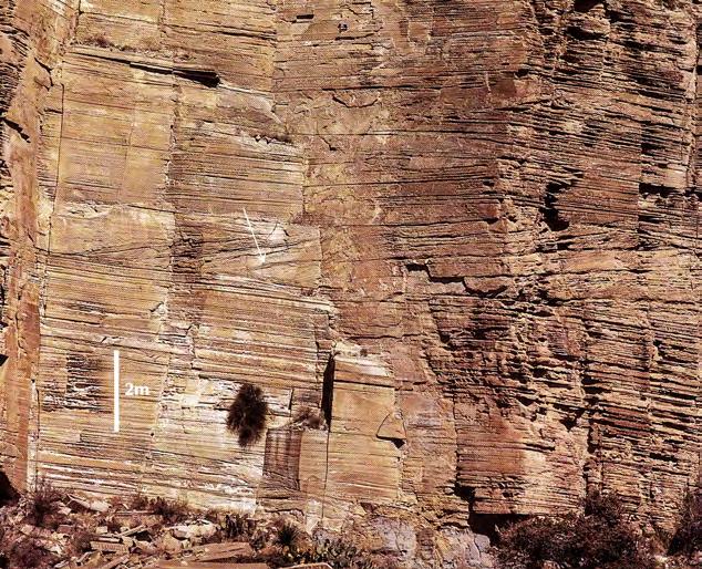
CHAPTER III TURBIDITE SYSTEMS: AN OUTCROP-BASED ANALYSIS 441
Fig. 511 - Exposures of the Permian Brushy Canyon Formation, west Texas: A possible example of an ancient bottom current deposit (after Mutti, 1992).
At this point, a somewhat substantial question may arise: Are we sure that these two different worlds can be significantly compared? My answer is that the comparison can be made but not without a critical appreciation of the differences. Sediment gravity flows, wave and tidal action, and everyday normal processes remain clearly the same, but their frequency and relative importance vary so much that facies associations, depositional elements and systems, and basin fill architectures may become difficult to compare. Orogenic belt basins, and especially foreland basins, are dwarfed by oceanic settings and do not share with them the variety of coastal configurations, oceanic currents, and huge, long-lived submarine features (e.g., some large fans and contourite drifts). They are essentialy relatively small, structurally controlled basins that receive huge amounts of sediment carried to the sea by many small and “dirty” rivers draining an adjacent growing orogen. Nonetheless, these are the basin fills from which most fundamental concepts of sedimentary geology have been developed since the 17th century mainly by European geologists. Reconciling this old school of thought with those emerged beginning in the second half of the 20th century, fundamentally based on the study of modern continental margins and new and ever-improving technologies, is not simple. The main problem is that these two ways of studying sedimentary successions deal very probably with two basically diìfferent datasets: on the one hand, sedimentary successions studied in the field, with emphasis on direct rock observations; on the other hand, seismic and marine geology data describing architectures and seascapes in great detail but lacking direct observations of rocks. From most recent literature it appears obvious that the second way of thinking is taking over, though with some risks (see below).
VII – ARTIFICIAL INTELLIGENCE AND QUALITY OF GEOLOGICAL INPUT DATA
In a period of time where sequence stratigraphic models dominate and most geological interpretations are essentially based upon seismic data or interpretations of outcrop data following seismic models and related terminology, this book has emphasized the problems encountered by a geologist when facing the interpretation of rocks, the way they are in outcrop or cores. In most cases, particularly when working in exposed orogenic belt basins, no seismic data are available and regional stratigraphic correlations and reconstructions are extremely difficult because of structural complexity and limited exposures. The fate of this kind of studies, despite some new technologies for outcrop analysis, seems sealed at this point. Extensive field work
requires time (and passion) and sequence stratigraphic approaches are certainly a useful, though dangerous, shortcut. Most commonly, however, these shortcuts forget that the in the Academia publish-or-be-lost is another way of killing extensive field work, which pays off only in the long term.
Geological modelling of sedimentary basins – another way to reduce time, risks and costs in the oil industry – is largely based on the assumption that what we already know about rocks and their origin is enough to go further and produce fancy, ever-moving and three-dimensional representations of these basins and the rock bodies they contain. I believe this is the future of sedimentary geology and I’m sure that with time artificial intelligence will take over. This book should however cast some doubt on a basic point: what do we really know about rocks? Well, in my long experience – both in Academia and Industry – I came to the conclusion that what we know about rocks is still quite limited, say around 30 percent of what we could extract from them.
I could also say that interpretations based on field studies change and keep changing quite often depending on the approach followed and the purposes of the work. Most rocks are increasingly studied and interpreted on the basis of their possible sequence stratigraphic significance rather than on their physical properties and sedimentological characteristics. This holds true at different scales, ranging from packets of beds to basin fill architectures. The example of the Eocene of the South-central Pyrenean foreland basin, with which I am most familiar, is very relevant from several points of view. The basin fill is very well exposed and has been studied in detail over the years by many authors. Yet, interpretations are still very different in terms of regional stratigraphic subdivisions, significance of depositional systems, down to the interpretation of beds and their formative processes (see Mutti, 2019 for an extensive discussion). If we had to model the fill of the basin or portions of it, we would be hardpressed to choose the input data for the computer and thus avoid geologically unreliable result. Which data would be most reliable? Yet, this exposed basin fill is one of the best known in the world.
My conclusion is that all geological interpretations should be considered as provisional, and geologists are thus involved in an endless attempt to improve them. A basic step in this process is a re-appreciation of field data, collected without pre-conceived ideas or universal models in our mind. Computers are and will be a tremendous tool for integrating huge amounts of data, sharpening our way of thinking and allow for great interpretations, provided we give them good data. What kind of rocks we are dealing with is probably a crucial
CHAPTER III TURBIDITE SYSTEMS: AN OUTCROP-BASED ANALYSIS 442
information required. Particularly in oil industry, it should be kept in mind that what we drill are rocks, not concepts.
VIII – THE FUTURE OF SEDIMENTARY GEOLOGY
The future of sedimentary geology is difficult to predict in the long term and even more difficult is to predict what kind of field geology will survive. In a near-future perspective, it is apparent that sedimentary geology is splitting into branches that are becoming increasingly separated from each other in terms of objectives, approach, scale and terminology. Communication is thus increasingly difficult among the scientific community, though the final goal should be the same. Oceanography, marine geology, high-resolution seismic, cyclostratigrapjy, geochronology, laboratory experiments, time-lapse monitoring of modern depositional systems, numerical modelling and theoretical considerations are creating new worlds where “old-fashion” geologists feel increasingly uncomfortable. By “old fashion” we should intend a very good geologist who is not specialized in a specific field of research, not necessarily aware of all the available literature, and is primarily concerned with what a geologist should routinely do: understanding the meaning of the rocks he observes in an exposed or buried basin, regardless of whether he is an academic or an explorationist. In most cases, this is a senior geologist who puts together all the available data collected by specialized professionals and attempts to provide a final and possibly easy-to-understand interpretation. Being this kind of geologist is extremely difficult today and such geologists are unfortunately becoming increasingly rare since geology itself is becoming more complex and specialized.
Based on my experience, I should say that in my career I came through very few geologists of this kind and they were primarily motivated by a strong passion for understanding rocks in a simple way, without preconceived ideas. Let me single out one example of such men. The late Charles (Chuck) V. Campbell, a geologist at Esso Production Research, has been an extraordinary example of intellectual freedom, to whom we owe the fundamental concept that seismic reflectors are essentially timelines (Campbell, 1967), a concept that revolutionized the way to interpret seismic lines. He was a master in finding, describing and interpreting bedding surfaces and taught me the way to look at the rocks during unforgettable field trips in the US, Italy and Spain. He was very humble and patient (at least with me) and his contributions have received relatively limited attention. I am convinced he was aware that
very few people would be able to understand what he was talking about, probably because he was expressing himself with few and simple words that did not impress the listener.
These problems are further complicated by most recent literature that describes progress in Earth sciences in articles that restrict communication to specialized élites. To this purpose, in a paper entitled “The Scientific Paper Is obsolete”, James Somers (2018) wrote:
“The more sophisticated science becomes, the harder it is to communicate results. Papers today are longer than ever and full of jargon and symbols. They depend on chains of computer programs that generate data, and clean up data, and plot data, and run statistical models on data. These programs tend to be both so sloppily written and so central to the results that it’s contributed to a replication crisis, or put another way, a failure of the paper to perform its most basic task: to report what you’ve actually discovered, clearly enough that someone else can discover it for themselves” (James Somers, “The Scientific Paper is obsolete”, The Atlantic, April 2018).
I fully agree with Somers’ conclusions, and firmly believe that simplicity is the only way to communicate. In the specific field of sedimentology and stratigraphy, it is amazing to see how many recent papers are full of diagrams, equations, and numerical data to support conclusions that should, in theory, ultimately help to understand rocks. Unfortunately, actual rocks are never mentioned and rather appear as an unwelcome guest. Most of these papers have very long lists of references and it is hard to believe that all of them have been carefully and critically read. Bibliometric indicators probably play here a major role, since they largely control the career of young scientists.
A necessary warning should be added at this point. This book has been written by a field geologist for young people who still like looking at the rocks with their bedding patterns, grain size, internal structures and stratigraphic relationships and try to interpret them in terms of inferred processes, environments and significance within the evolution of the basin fill under consideration. As mentioned above, this kind of approach suffers at present severe limitations, being gradually replaced by new approaches aiming at looking at rocks from a wide-ranging perspective (see above), implying that what we know about rocks is probably enough or not so important for their purposes. Some of the arguments for and against these new approaches have been discussed in the preceding pages and the only reasonable conclusion that can be drawn is that a better integration of field data into these approaches would be highly desirable.
CHAPTER III TURBIDITE SYSTEMS: AN OUTCROP-BASED ANALYSIS 443
During the last two decades, geochronology and thermochronology have started to revolutionize our conventional methods of dating rocks, events and rates of geological processes by isotopic dating (numerical or absolute dating). These methods have been successfully used in provenance studies and tectonic evolution of source areas and are now being gradually applied to basin analysis and to the “source-to-sink” problem.
Conceptually, the final goal of this new approach has been amply discussed by Romans et al. (2016, with references therein) in an excellent paper on the various external and internal environmental forcings that on different timescales affect landscapes, transfer zones and sinks of sedimentary basins. These forcings, i.e., variations in precipitation, sea level, uplift and subsidence, leave environmental signals recorded by changes in sediment production, transport, or deposition that propagate and interact across sediment-routing systems at different timescales, controlling the “sourceto-sink” process, ideally the fate of a clastic particle from its source to the final sink (Figure 512). The timescales considered include: 1) historic (decades to centuries), 2) intermediate (centuries to several millions of years), and 3) deep time ( –> 107 yr). The approach described by Romans et al. (2016) to interpret landscape
dynamics from the stratigraphic record (Figure 513) is certainly fascinating and implies a necessary multidisciplinary study but is heralding a kind of studies that is still in the dreamland and apparently overlooks how far we are from correctly interpreting the stratigraphic record, i.e., the rocks.
It is clear, however, that sedimentary geology is progressively moving toward interdisciplinary approaches that necessarily tend to use all the techniques and data emerging from the many and different sub-disciplines of earth sciences. The improvement of our knowledge is mainly depending upon the correct and well-balanced integration of all this information possibly with the underlying common goal of obtaining easy-to-understand geological interpretations. From the scheme in the lower diagram of Figure 512, which sets the conceptual framework of a multidisciplinary approach, there appears to be ample room for fieldbased stratigraphic and sedimentological information, which is still the best tool to describe and understand the potential stratigraphic record (in yellow) of the many signals left by the original forcings through time. Hopefully, this should secure the future of field-based geologists for a while.
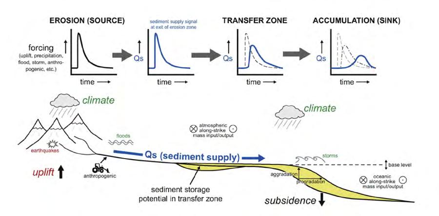
CHAPTER III TURBIDITE SYSTEMS: AN OUTCROP-BASED ANALYSIS 444
A B
Fig. 512 - A. Propagation and modifications of the sediment supply (Qs) signal from the source to the final depositional zone (stratigraphic record); B. Erosion, transfer and depositional zones along an ideal sediment-routing system showing the main factors controlling the process and its stratigraphic preservation (in yellow). From Romans et al. (2016).

CHAPTER III TURBIDITE SYSTEMS: AN OUTCROP-BASED ANALYSIS 445
Fig. 513 - The three basic timescales of investigation and chronometric tools to constrain process rates, and periods of time during which some forcings are acting. It will be noted that studying sedimentary successions through this holistic approach would be impossible in the practice though a challenge for future research. From Romans et al. (2016).
REFERENCES
ABREU, V.; SULLIVAN, M.; PIRMEZ, C.; MOHRIG, D. Lateral accretion packages (LAPs): an important reservoir element in deep water sinuous channels. Marine and Petroleum Geology, Guildford, v. 20, p. 631-648, 2003.
AGER, D. V. The new catastrophism: the importance oh the rare event in geological history. Cambridge: Cambridge University Press, 1993.
AINSWORTH, R.B. Marginal marine sedimentology and high resolution sequence analysis; Bearpaw - Horseshoe Canyon transition, Drumheller, Alberta. Bulletin of Canadian Petroleum Geology, McLean, v. 42, p. 26-54. 1994
ALLEN, J. R. L. Studies of fluviatile sedimentation: six cyclothems from the Lower Old Red Sandstone, Anglo-Welsh basin. Sedimentology, v. 3, p. 163–198, 1964.
ALLEN, P.A. Sediment Routing Systems - The Fate of Sediment from Source to Sink. New York: Cambridge University Press, 2017.
AMY, L. A.; TALLING, P. J. Anatomy of turbidites and linked debrites based on long distance (120 x 30 km) bed correlation, Marnoso Arenacea Formation, Northern Apennines, Italy. Sedimentology, Oxford, v. 53, n. 1, p. 161-212, Feb. 2006.
ARGAND, E. Sur l’arc des Alpes occidentales. Lausanne: Bridel, 1916. (Eclogae Geologicae Helvetiae, 14).
BAKER, V. R.; BUNKER, R. C. Cataclysmic late Pleistocene flooding from glacial lake Missoula: a review. Quarternary Science Review, Oxford, v. 4, n. 1, p. 1-41, 1985.
BARNES, N. E.; NORMARK, W. R. Diagnostic parameters for comparing modern submarine fans and ancient turbidite systems. In: BOUMA, A. H.; NORMARK, W. R.; BARNES, N. E. (ed.). Submarine fans and related turbidite systems. New York: Springer-Verlag, 1985. p. 13-14.
BATES, C. C. Rational theory of delta formation. American Association of Petroleum Geologists Bulletin, Tulsa, v. 37, n. 9, p. 2119-2162, Sept. 1953.
BEAUBOUEF, R.T.; ROSSEN, C.; ZELT, F.B.; SULLIVAN, M.D.; MOHRIG, D.C.; JENNETTE, D.C. 1999. Deep-water sandstones of the Brushy Canyon Formation, west Texas, Field Guide, American Association of Petroleum Geologists, Hedberg Field Research Conference, April 15-20, 48 pp.
BHATTACHARYA, J. P. Deltas. In: POSAMENTIER, H. W.; WALKER, R. G. (ed.). Facies models revisited. Tulsa: Society for Sedimentary Geology, 2006. p. 237-292. (Society for Sedimentary Geology. Special publication, 84).
BHATTACHARYA, J.P. Deltas. In: Dalrymple, R.G.; James, N.P. (Eds.), Facies Models, Fourth Edition. St. John’s: Geological Association of Canada, Geotext 6, p. 233–264, 2010.
BLAIR, T. C.; MCPHERSON, J. G. Alluvial fan processes and forms. In: ABRAHAMS, A. D.; PARSONS, A. J. (ed.). Geomorphology of desert environments. Dordrecht: Springer, 1994b. p. 354-402.
BLAIR, T. C.; MCPHERSON, J. G. Alluvial fans and their natural distinction from rivers based on morphology, hydraulic processes, sedimentary processes, and facies assemblages. Journal of Sedimentary Research - Section A: sedimentary petrology and processes, Tulsa, v. 64, n. 3a, p. 450-489, July, 1994a.
BLATT, H.; MIDDLETON, G.; MURRAY, R. Origins of Sedimentary Rocks. New Jersey: Prentice-Hall, 634 pp., 1972.
BOERSMA, J. R.; TERWINDT, J. H. J. Neap–spring tide sequences of intertidal shoal deposits in a mesotidal stuary. Sedimentology, Oxford, v. 28, n. 2, p. 151-170, Apr. 1981.
BORNHOLD, B. D.; PRIOR D. B. Morphology and sedimentary processes on the subaqueous Noeick River delta, British Columbia, Canada. In: BORNHOLD, B. D.; PRIOIR, D. B. (ed.). Coarse-grained deltas. Oxford: Blackwell Scientific, 1990. p. 169-181. (International Association of Sedimentologists. Special publication, 10).
CHAPTER III TURBIDITE SYSTEMS: AN OUTCROP-BASED ANALYSIS 446
BORNHOLD, B. D.; REN, P.; PRIOR, D. B. High-frequency turbidity currents in British Columbia fjords. Geo-Marine Letters, Heidelberg, v. 14, n. 1, p. 238-243, Dec. 1994.
BOSELLINI, A.; MUTTI, E.; RICCI LUCCHI, F. Rocce e successioni sedimentarie. Torino: Utet, 395 p., 1989.
BOTVINKINA, L. N. Slosistot osadochaykh porod (Bedding of sedimentary rocks). Akad. Nauk. U.S.S.R., Trudy Geol. Inst., no. 59, 542 p. 1962.
BOUMA, A. H. Sedimentology of some flysch deposits: a graphic approach to facies interpretation. Amsterdam: Elsevier, c1962.
BOUMA, A. H.; BROUWER, A. (ed.). Turbidites. Amsterdam: Elsevier, 1964. (Developments in sedimentology, 3).
BOUMA, A. H.; NORMAK, W. R.; BARNES, N. (ed.). Submarine fans and related turbidite systems. New York: Springer, 1985a.
BOUMA, A. H.; NORMARK, W. R.; BARNES, N. E. COMFAN: needs and initial results. In: BOUMA, A. H.; NORMAK, W. R.; BARNES, N. (ed.). Submarine fans and related turbidite systems. New York: Springer, 1985b. p. 7-11.
BOUMA, A. H.; STELTING, C. E.; COLEMAN, J. M. Mississippi Fan, Gulf of Mexico. In: BOUMA, A. H.; NORMAK, W. R.; BARNES, N. (ed.). Submarine fans and related turbidite systems. New York: Springer, 1985c. p. 143-150.
BRETZ, J. H. The Spokane flood beyond the channeled Scabland. Journal of geology, Chicago, v. 33, n. 2, p. 97115, 236-259, Feb./Mar. 1925.
BRIDGE, J. S. Fluvial facies models: recent evelopments. In: POSAMENTIER, H. W.; WALKER, R. G. (ed.). Facies models revisited. Tulsa: Society for Sedimentary Geology, 2006. p. 85-170. (Society for Sedimentary Geology. Special publication, 84).
BRISTOW, C.S. Sedimentology of the Rough Rock: a Carboniferous braided river sheet sandstone in northern England. In: BEST, J. L.; BRISTOW, C. S. (Eds.), Braided Rivers. Geological Society, London, Special Publications, v. 75, p. 291 – 304, 1993.
BROWN, L., F.; FISHER, W. L. Seismic-stratigraphic interpretation of depositional systems: examples from Brazilian rift and pull-apart basins, in: Payton, C., E., ed., Seismic Stratigraphy—Applications to Hydrocarbon Exploration: AAPG Memoir 26, p. 213–248. 1977.
CAMPBELL, C. V. Lamina, laminaset, bed and bedset. Sedimentology, Oxford, v. 8, n. 1, p. 7-26, Feb. 1967.
CANTERO, M. I.; CANTELLI, A.; PIRMEZ, C.; BALACHANDAR, S.; MOHRIG, D.; HICKSON, T. A.; YE, T.; NARUSE, H.; PARKER, G. Emplacement of massive turbidites linked to extinction of turbulence in turbidity currents. Nature Geoscience, London, v. 5, n. 1, p. 42-45, Nov. 2012.
CAPELLA, W.; HERNANDEZ-MOLINA, F. J.; FLECKER, R.; HILGEN, F. J.; HSSAIN, M.; KOUWENHOVEN, T. J.; OORSCHOT, M.; SIERRO, F. J.; STOW, D. A. V.; TRABUCHO-ALEXANDRE, J.; TULBURE, M. A.; WEGER, W.; YOUSFI, M. Z.; KRIJGSMAN, W. Sandy contourite drift in the late Miocene Rifian Corridor (Morocco): reconstruction of depositional environments in a foreland-basin seaway. Sedimentary Geology, Amsterdam, v. 355, p. 31-57, June 2017.
CARMINATTI, M. Stratigrafia fisica e modellizzazione sismica invers dell’ Allogruppo di Figols (Pirenei centro-meridionali, Spagna). 1992. 164 f. Tese (Doutorado) – Università di Parma, Parma, Italia, 1992.
CARTER, R. M. A discussion and classification of subacqueous mass transport with particular application to grain–flow, slurry-flow, fluxoturbidites. Earth Science Reviews, Amsterdam, v. 11, n. 2, p. 145-177, June 1975.
CARTIGNY, M. J. B.; VENTRA, D.; POSTMA, G.; BERG, J. H. van den. Morphodynamics and sedimentary structures of bedforms under supercritical-flow conditions: new insights from flume experiments. Sedimentology, Oxford, v. 61, n. 3, p. 712-748, 2014.
CARVAJAL, C.; STEEL, R. Shelf-edge architecture and bypass of sand to deep water: influence of shelf-edge processes, sea level, and sediment supply. Journal of Sedimentary Research, Tulsa, v. 79, n. 9, p. 652-672, Sept. 2009.
CHAPTER III TURBIDITE SYSTEMS: AN OUTCROP-BASED ANALYSIS 447
CASNEDI, R. Hydrocarbon-bearing submarine fan system of Cellino Formation, Central Italy. American Association of Petroleum Geologists Bulletin, Tulsa, v. 67, n. 3, p. 359-370, Mar. 1983.
CATUNEANU, O. Principles of Sequence Stratigraphy. Amsterdam: Elsevier. 375 pp. 2006
CATUNEANU, O.; ABREU, V.; BHATTACHARYA, J. P.; BLUM, M. D.; DALRYMPLE, R. W.; ERIKSSON, P. G.; FIELDING, C. R.; FISHER, W. L.; GALLOWAY, W. E.; GIBLING, M. R.; GILES, K. A.; HOLBROOK, J. M.; JORDAN, R.; KENDALL, C. G. St. C.; MACURDA, B.; MARTINSEN, O. J.; MIALL, A. D.; NEAL, J. E.; NUMMEDAL, D.; POMAR, L.; POSAMENTIER, H. W.; PRATT, B. R.; SARG, J. F.; SHANLEY, K. W.; STEEL, R. J.; STRASSER, A.; TUCKER, M. E.; WINKER, C. Towards the standardization of sequence stratigraphy. Earth Science Reviews, Amsterdam, v. 92, n. 1/2, p. 1-33, Jan. 2009.
CATUNEANU, O.; GALLOWAY, W.E.; KENDALL, C.G.ST.C.; MIALL, A.D.; POSAMENTIER, H.W.; STRASSER, A.; TUCKER, M.E. Sequence stratigraphy: methodology and nomenclature. Newsl. Stratigr., Stuttgart, v. 44, p. 173–245, 2011
CHAN, M. A.; DOTT JUNIOR, R. H. Shelf and deep-sea sedimentation in Eocene forearc basin, western Oregon: fan or no fan? American Association of Petroleum Geology. Bulletin, Tulsa, v. 67, n. 11, p. 2100-2116, Nov. 1983.
CHEEL, R. J. Introduction to clastic sedimentology. Ontario: Brock University. Department of Earth Sciences, 2005.
CLARK, J. D.; CASTELLTORT, S.; PUIGDEFABREGAS, C.; FILDANI, A. Propagation of environmental signals within source to sink stratigraphy. In: CLARK, J. D.; PUIGDEFABREGAS, C.; CASTELLTORT, S.; FILDANI, A. (ed.). Propagation of environmental signals within source-to-sink stratigraphy. [Tulsa]: Society of Economic Paleontologists and Mineralogists, 2017. (Society of Economic Paleontologists and Mineralogists. Field Trip Guidebook, 13).
CLARK, J. D.; PICKERING, K. T. Submarine channels: processes and architecture. London: Vallis, 1996.
CLARKE, J. E. H.; SHOR, A. N.; PIPER, D. J. W.; Mayer, L. A. Large-scale current-induced erosion and deposition in the path of the 1929 Grand Banks tubidity current. Sedimentology, Oxford, v. 37, n. 4, p. 613-629, Aug. 1990.
CLIFTON, H. E. Sedimentologic relevance of convulsive geologic events. In: CLIFTON, H. E. (ed.). Sedimentologic consequences of convulsive geologic events. Boulder: Geological Society of America, 1988. p. 1-5. (Geological Society of America. Special paper, 229).
COLEMAN, J. M. Brahmaputra river: channel processes and sedimentation. Sedimentary Geology, Amsterdam, v. 3, n. 2/3, p. 129-239, Aug. 1969.
COLEMAN, J. M.; GAGLIANO, S. M. Sedimentary structures: Mississippi river deltaic plain. In: MIDDLETON, G. V. (ed.). Primary sedimentary structures and their hydrodynamic interpretation. Tulsa: Society of Economic Paleontologists and Mineralogists, 1965. p. 133-148. (Society for Sedimentary Geology. Special publication, 12).
COLEMAN, J. M.; WRIGHT, L. D. Modern river deltas: variability of processes and sand bodies. In: BROUSSARD, M. L. S. (ed.). Deltas: models for exploration. Houston: Geological Society of America, c1975. p. 99-149.
COLLINSON, J. D. Alluvial sediments. In: READING, H. G. (ed.). Sedimentary environment and facies. Oxford: Blackwell Scientific. 1986. p. 20-62.
COLLINSON, J. D. Alluvial sediments. In: READING, H. G. (ed.). Sedimentary environments: processes, facies and stratigraphy. 3rd ed. Oxford: Blackwell, 1996. p. 37-81.
COVAULT, J. A.; SYLVESTER, Z.; HUBBARD, S. M.; JOBE, Z. R.; SECH, R. P. The stratigraphic record of submarine-channel evolution. The Sedimentary Record, Tulsa, v. 14, n. 3, p. 4-11, Sept. 2016.
CROWELL, J. C. Directional-current structures from the Prealpine Flysch, Switzerland. Geological Society of America Bulletin, New York, v. 66, n. 11, p. 1351-1384, Nov. 1955.
CROWELL, J. C. Origin of Pebbly Mudstones. Geological Society of America Bulletin, New York, v. 68, n.8., p. 9931010, 1957.
CUNHA, R. S.; TINTERRI, R.; MAGALHAES, P. M. Annot Sandstone in the Peïra Cava basin: an example of an asymmetric facies distribution in a confined turbidite system (SE France). Marine and Petroleum Geology, Guildford, v. 87, p. 60-79, Nov. 2017.
CHAPTER III TURBIDITE SYSTEMS: AN OUTCROP-BASED ANALYSIS 448
CURRAY, J. R. Transgressions and regressions. In Papers in Marine Geology (R. L. Miller, Ed.), pp. 175–203. New York: Macmillan. 1964.
DARLYMPLE, R. W. Tidal depositional systems. In: JAMES, N. P.;DALRYMPLE, R. W. (ed.). Facies models 4. St. John’s: Geological Association of Canada, 2010. p. 201-231.
DEPTUCK, M. E.; PIPER, D. J. W.; SAVOYE, B.; GERVAIS, A. Dimensions and architecture of late Pleistocene submarine lobes off the northern margin of East Corsica. Sedimentology, Oxford, v. 55, n. 4, p. 869-898, Aug. 2008.
DEPTUCK, M. E.; STEFFENS, G. S.; BARTON, M.; PIRMEZ, C. Architecture and evolution of upper fan channel-belts on the Niger Delta slope and in the Arabian Sea. Marine and Petroleum Geology, Guildford, v. 20, n. 6/8, p. 649676, June/Sept. 2003.
DE RAAF, J.F.M.; READING H. G.; WALKER, R. G. Cyclic sedimentation in the lower Westphalian of North Devon, England. Sedimentology, Oxford, v. 4, p. 1–52, 1965.
DE ROSA, R.; ZUFFA, G. G. Le areniti ibride della Valle di Ager (Eocene, Pirenei centro-meridionali). Mineralogica et Petrographica Acta, Bologna, v. 23, p. 1-12, 1979.
DORRELL, R. M.; PEAKALL, J.; SUMNER, E. J.; PARSONS, D. R.; DARBY, S. E.; WYNN, R. B.; ÖZSOY, E.; TEZCAN, D. Flow dynamics and mixing processes in hydraulic jump arrays: implications for channel-lobe transition zones. Marine Geology, Amsterdam, v. 381, p. 181-193, Nov. 2016.
DOTT, R. H. An episodic view of shallow marine clastic sedimentation. In: BOER, P. L.; Gelder, A. van; Nio, S.-D. (ed). Tide-influenced sedimentary environments and facies. Dordrecht: D. Reidel, 1988. p. 3-12.
DOTT, R. H. Dynamics of subaqueous gravity depositional processes. Geological Society of America Bulletin, New York, v. 47, n. 1, p. 104-128, Jan. 1963.
DOTT, R. H. Episodic sedimentation: how normal is average? How rare is rare? Does it matter? Journal of Sedimentary Petrology, Tulsa, v. 53, n. 1, p. 5-23, Mar. 1983.
DRAGO, M.; CONSONNI, A.; TINTERRI, R. Numerical simulations of subaqueous bipartite gravity flows. In: OFFSHORE MEDITERRANEAN CONFERENCE AND EXHIBITION, 7., 2005, Ravenna. Proceedings […]. Ravenna: Offshore Mediterranean Conference, c2005. p. 1-12.
DUKE, W. L. Hummocky cross-stratification, tropical hurricanes, and intense winter storms. Sedimentology, Oxford, v. 32, n. 2, p. 167-194, Apr. 1985.
DZULYNSKI, S.; KSIAZKIEWICZ, M.; KUENEN, H. Turbidites in flysch of the polisch carpathian mountains. Geological Society of America Bulletin, New York, v. 70, n. 8, p. 1089-1118, Aug. 1959.
DZULYNSKI, S.; SANDERS, J. E. Current marks on firm mud bottoms. New Haven: Published by the Academy, 1962. p. 57-96. (Transactions of the Connecticut Academy of Arts and Sciences, v. 42).
EINSELE, G.; RICKEN, W.; SEILACHER, A. (Eds.) Cycles and Events in Stratigraphy. Springer-Verlag (955 pp), 1991
ELLIOTT, T. Deltas. In: READING, H. G. (ed.). Sedimentary environments and facies. 2nd ed. Oxford: Blackwell Scientific, 1986. p. 113-154.
ELLIOTT, T. Megaflute erosion surfaces and the initiation of turbidite channels. Geology, Boulder, v. 28, n. 2, p. 119–122, 2000.
EMBRY, A.F.; JOHANNESSEN, E.P. T–R sequence stratigraphy, facies analysis and reservoir distribution in the uppermost Triassic- Lower Jurassic succession, western Sverdrup Basin, Arctic Canada. In: Vorren, T.O., Bergsager, E., Dahl-Stamnes, O.A., Holter, E., Johansen, B., Lie, E., Lund, T.B. (Eds.), Arctic Geology and Petroleum Potential vol. 2. Norwegian Petroleum Society (NPF), pp. 121–146 (Special Publication), 1992.
FEDELE; J. J.; BARNAAL; Z.; TULENKO; J.; AND AWALT; S. Bedforms created by gravity flows, IN Budd, D. A., Hajek, E. A., and Purkis, S. J. (Eds.) Autogenic dynamics and self-organization in sedimentary systems. Tulsa: SEPM, Special Publication, v. 106, p. 65–121, 2016.
CHAPTER III TURBIDITE SYSTEMS: AN OUTCROP-BASED ANALYSIS 449
FESTA, A.; DILEK, Y.; PINI, G. A.; CODEGONE, G.; OGATA, K. Mechanisms and processes of stratal disruption and mixing in the development of mélanges and broken formations: redefining and classifying mélanges. Tectonophysics, Amsterdam, v. 568/569, p. 7-24, Sept. 2012.
FIELDING, C. R. Upper flow regime sheets, lenses and scour fills: extending the range of architectural elements for fluvial sediment bodies. Sedimentary Geology, Amsterdam, v. 190, n. 1/4, p. 227-240, Aug. 2006.
FIELDING, C. R.; TRUEMAN, J .D.; ALEXANDER, J. Sharp-based, flood-dominated mouth bar sands from the Burdekin River Delta of northeastern Australia: extending the spectrum of mouth-bar facies, geometry, and stacking patterns. Journal of Sedimentary Research, Tulsa, v. 75, n. 1, p. 55-66, Jan. 2005.
FILDANI, A.; HUBBARD, S. M.; COVAULT, J. A.; MAIER, K. L.; ROMANS, B. W.; TRAER, M.; ROWLAND, J. C. Erosion at inception of deep-sea channels. Marine and Petroleum Geology, Guildford, v. 41, p. 48-61, Mar. 2013.
FISHER, W.L.; MCGOWEN, J.H. Depositional systems in the Wilcox group of Texas and their relationship to occurrence of oil and gas. Trans. Gulf Coast Assoc. Geol. Soc. v. 17, p. 105–125. 1967
FONNESU, F. The Mamba Complex Supergiant Gas Discovery (Mozambique): an Example of Turbidite Fans Modified by Deepwater Tractive Bottom Currents. The 12th PESGB/HGS Conference on African E&P, London, 2013.
FONNESU, M.; FELLETTI, F.; HAUGHTON, P. D. W.; PATACCI, M.; MCCAFFREY, W. D. Hybrid event bed character and distribution linked to turbidite system sub-environments: the North Apennine Gottero Sandstone (north-west Italy). Sedimentology, Oxford, v. 65, n. 1, p. 151-190, Jan. 2018.
FONNESU, M.; HAUGHTON, P.; FELLETTI, F.; MCCAFFREY, W. Short length-scale variability of hybrid event beds and its applied significance. Marine and Petroleum Geology, Guildford, v. 67, p. 583-603, Nov. 2015.
FONNESU, M.; PALERMO, D.; GALBIATI, M.; MARCHESINI, M.; BONAMINI, E.; BENDIAS, D. A new world-class deep-water play-type, deposited by the syndepositional interaction of turbidity flows and bottom currents: the giant Eocene Coral Field in northern Mozambique. Marine and Petroleum Geology, Guildford, v. 111, p. 179-201, Jan. 2020.
FONNESU, M.; PATACCI, M.; Haughton, P.D.W.; FELLETTI, F.; McCAFFREY, W.D. Hybrid Event Beds Generated by Local Substrate Delamination on a Confined-Basin Floor. Journal of Sedimentary Research, Tulsa, v. 86, n.8. p. 929-943, 1996.
GALLOWAY, W. E. Process framework for describing the morphologic and stratigraphic evolution of deltaic depositional systems. In: BROUSSARD, M. L. S. (ed.). Deltas: models for exploration. Houston: Geological Society of America, c1975. p. 87-98.
GARDNER, M. H.; BORER, J. M.; MELICK, J. J.; MAVILLA, N.; DECHESNE, M.; WAGERLE, R. N. Stratigraphic process-response model for submarine channels and related features from studies of Permian Brushy Canyon outcrops, West Texas. Marine and Petroleum Geology, Guildford, v. 20, n. 6/8, p. 757-788, June/Sept. 2003.
GHIBAUDO, G. Subaqueous sediment gravity flow deposits: practical criteria for their field description and classification. Sedimentology, Oxford, v. 39, n. 3, p. 423-454, June 1992.
GHIELMI, M.; MINERVINI, M.; NINI, C.; ROGLEDI, S.; ROSSI, M. Late Miocene–Middle Pleistocene sequences in the Po Plain–Northern Adriatic Sea (Italy): the stratigraphic record of modification phases affecting a complex foreland basin. Marine and Petroleum Geology, Guildford, v. 42, p. 50-81, Apr. 2013.
GIGNOUX, M. Stratigraphic geology. California: Freeman & Company, 682p. 1950.
GOLDRING, R.; BRIDGES, P. Sublittoral sheet sandstones. Journal of Sedimentary Petrology, Tulsa, v. 43, n. 3, p. 736-747, Sept. 1973.
GORSLINE, D. S.; EMERY, K. O. Turbidity-current deposits in San Pedro and Santa Monica basins off southern California. Geological Society of America Bulletin, New York, v. 70, n. 3, p. 279-290, Mar. 1959.
CHAPTER III TURBIDITE SYSTEMS: AN OUTCROP-BASED ANALYSIS 450
GOULD, H. R. The Mississippi delta complex. In: MORGAN, J. P.; SHAVER, R. H. (ed). Deltaic sedimentation: modern and ancient. Tulsa: Society of Economic Paleontologists and Mineralogists, 1970. p. 3-30. (Society of Economic Paleontologists and Mineralogists. Special publication, 15).
GRESSLY, A. Observations géologiques sur le Jura soleu-rois. Nouveaux mémoires de la Société Helvetique desSciences Naturelles, v. 2, 349 p., 1838
HANER, B. E. Morphology and sediments of Redondo submarine fan, southern California. Geological Society of America Bulletin, New York, v. 82, n. 9, p. 2413-2432, Sept. 1971.
HARMS, J. C.; FAHNESTOCK, P. Stratification, bed forms and flow phenomena (with an example from Rio Grande). In: MIDDLETON, G. V. (ed.). Primary sedimentary structures and their hydrodynamic interpretations. Tulsa: Society of Economic Paleontologists and Mineralogists, 1965. p. 84-115. (Society of Economic Paleontologists and Mineralogists. Special Publication, 12).
HARMS, J. C.; SOUTHARD, J. B.; WALKER, R. G. Structures and sequences in clastic rocks. Tulsa: Society of Economic Paleontologists and Mineralogists, 1982. (Society of Economic Paleontologists and Mineralogists. Lecture Notes for Short Course, 9).
HARMS, J. C.; WILLIAMSON, C. R. Deep-water density current deposits of Delaware Mountain Group (Permian), Delaware Basin, Texas and New Mexico. American Association of Petroleum Geologists Bulletin, Tulsa, v. 27, n. 3, p. 299-317, Mar. 1988.
HARVEY, A. M.; MATHER, A. E.; STOKES, M. Alluvial fans: geomorphology, sedimentology, dynamics: introduction. A review of alluvial-fan research. In: HARVEY, A. M.; MATHER, A. E.; STOKES, M. (ed.). Alluvial fans: geomorphology, sedimentology, dynamics. London: Geological Society, 2005. p. 1-7 (Geological Society of London. Special publications, 251).
HAUGHTON, P. D. W.; BARKER, S. P.; MCCAFFREY, W. D. ‘Linked’ debrites in sand-turbidite systems: origin and significance. Sedimentology, Oxford, v. 50, n. 3, p. 459-482, June 2003.
HAUGHTON, P.; DAVIS, C.; MCCAFFREY, W.; BARKER, S. Hybrid sediment gravity flow deposits: classification, origin and significance. Marine and Petroleum Geology, Guildford, v. 26, n. 10, p. 1900-1918, Dec. 2009.
HEEZEN, B. C.; HOLLISTER, C. D.; RUDDIMAN, W. F. Shaping of the continental rise by deep geostrophic currents. Science, Washington, v. 152, n. 3271, p. 502-508, Apr. 1966.
HEIN, F. J.; WALKER, R. G.The Cambro‐Ordovician Cap Enragé Formation, Queébec, Canada: conglomeratic deposits of a braided submarine channel with terraces. Sedimentology, Oxford, v. 29, n. 3, p. 309-352, June 1982.
HEINIÖ, P.; DAVIES, R. J. Knickpoint migration in submarine channels in response to fold growth, western Niger Delta. Marine and Petroleum Geology, Guildford, v. 24, n. 6/9, p. 434-449, June/Nov. 2007.
HELLER, P. L.; DICKINSON, W. R. Submarine ramp facies model for delta-fed, sand-rich turbidite sytems. American Association of Petroleum Geologists Bulletin, Tulsa, v. 69, n. 6, p. 960-976, June 1985.
HISCOTT, R. N.; MIDDLETON, G. V. Depositional mechanics of thick-bedded sandstones at the base of a submarine slope, Tourelle formation (lower ordovician), Quebec, Zanada. In: DOYLE, L. J.; PILKEY, O. H. (ed.). Geology of continental slopes. Tulsa: Society of Economic Paleontologists and Mineralogists, 1979. p. 307-326. (Society of Economic Paleontologists and Mineralogists. Special publication, 27).
HIZZETT; J.L.; CLARKE, H. J.E.; SUMNER, E.J.; CARTIGNY, M.J.B.; TALLING, P.J.; CLARE, M.A. Which triggers produce the most erosive, frequent , and ongest runout turbidity currents on Deltas? Geophysical Research Letters, Washington, v. 45, n. 2, p. 855-863, Jan. 2017.
HOLLISTER, C. D.; HEEZEN, B. C. Contour current evidence from abyssal sediments. Transactions / American Geophysical Union, Washington, v. 48, p. 142, 1967.
HUBERT, J. F. Modification of the model for internal structures in graded beds to include a dune division. Nature, London, v. 211, n. 5049, p. 614-615, Aug. 1966.
CHAPTER III TURBIDITE SYSTEMS: AN OUTCROP-BASED ANALYSIS 451
HUGGETT, R. Cataclysms and earth history: the development of diluvialism. Oxford: Claredon Press, c1989.
HUGGETT, R. Catastrophism: systems of earth history. London: E. Arnold, 1990.
HUNT, D.; TUCKER, M. E. Stranded parasequences and the forced regressive wedge systems tract: deposition during base-level’fall. Sedimentary Geology, Amsterdam, v. 81, n. 1/2, p. 1-9, Nov. 1992.
IVERSON, R. M. The physics of debris flows. Reviews of Geophysics, Hoboken, v. 35, n. 3, p. 245-296, Aug. 1997.
JAMES, N. P.; DALRYMPLE, R. W. (ed.). Facies models 4. St. John’s: Geological Association of Canada, 2010.
JOHNS, D. R.; MUTTI, E.; ROSELL J.; SEGURET, M. Origin of a thick redeposited carbonate bed in the Eocene turbidites of the Hecho Group, south central Pyrenees, Spain. Geology, Boulder, v. 9, n. 4, p. 161-164, Apr. 1981.
JOPLING, A. V. Laboratory study of the distribution of grain size in cross-bed deposits. In: MIDDLETON, G. V. (ed.). Primary sedimentary structure and their hydrodynamic interpretation. Tulsa: Society of Economic Paleontologists and Mineralogists, 1965. p. 53-65. (Society of Economic Paleontologists and Mineralogists. Special Publication, 12).
JOPLING, A. V.; WALKER, R. G. Morphology and origin of ripple-drift cross lamination, with examples from the Pleistocene of Massachusets. Journal of Sedimentary Petrology, Tulsa, v. 38, n. 4, p. 971-984, Dec. 1968.
KNELLER, B. C.; BRANNEY, M. J. Sustained high‐density turbidity currents and the deposition of thick massive sands. Sedimentology, Oxdord, v. 42, n. 4, p. 607-616, Aug. 1995.
KOSTIC, S.; PARKER, G. The response of turbidity currents to a canyon–fan transition: internal hydraulic jumps and depositional signatures. Journal of Hydraulic Research, Delft, v. 44, n. 5, p. 631-653, Apr. 2006.
KRUMBEIN, W. C.; SLOSS, L. L. Stratigraphy and Sedimentation. San Francisco: W.H. Freeman. 1958
KUENEN, H. Sole markings of graded graywacke beds. Journal of Geology, Chicago, v. 65, n. 3, p. 231-258, May 1957.
KUENEN, H.; MIGLIORINI, C. I. Turbidity currents as a cause of graded bedding. Journal of Geology, Chicago, v. 58, n. 2, p. 91-127, Mar. 1950.
LABAUME, P.; MUTTI, E.; SEGURET, M. Megaturbidites: a depositional model from the Eocene of the SW-Pyrenean foreland basin, Spain. Geo-Marine Letters, Heidelberg, v. 7, n. 2, p. 91-101, 1987.
LAMB, M. P.; MCELROY, B.; KOPRIVA, B.; SHAW, J.; MOHRIG, D. Linking river-flood dynamics to hyperpycnal-plume deposits: experiments, theory, and geological implications. Geological Society of America Bulletin, New York, v. 122, n. 9/10, p. 1389-1400, Sept. 2010.
LANG, J.; BRANDES, C.; WINSEMANN, J. Erosion and deposition by supercritical density flows during channel avulsion and backfilling: field examples from coarse-grained deepwater channel-levée complexes (Sandino Forearc Basin, southern Central America). Sedimentary Geology, Amsterdam, v. 349, p.79-102, Mar. 2017.
LOMBARD, A. Séries sédimentaires: genèse, evolution. Paris: Masson, 1972.
LOWE, D. R. Grain flow and grain flow deposits. Journal of Sedimentary Research, Tulsa, v. 46, n. 1, p. 188-199, Mar. 1976.
LOWE, D. R. Sediment gravity flows II: depositional models with special reference to the deposits of high-density turbidity currents. Journal of Sedimentary Petrology, Tulsa, v. 52, n. 1, p. 279-297, Mar. 1982.
LOWE, D. R. Sediment gravity flows: their classification and some problems of application to natural flows and deposits. In: DOYLE, L. J.; PILKEY, O. H. (ed.). Geology of continental slopes. Tulsa: Society of Economic Paleontologists and Mineralogists, 1979. p. 75-82. (Society of Economic Paleontologists and Mineralogists. Special publication, 27).
LYELL, C. Principles of geology. New York: Johnson Reprint Corp., 1969. 3 v.
CHAPTER III TURBIDITE SYSTEMS: AN OUTCROP-BASED ANALYSIS 452
MAGALHAES, P. M.; TINTERRI, R. Stratigraphy and depositional setting of slurry and contained (reflected) beds in the Marnoso-arenacea formation (Langhian Serravallian) Northern Apennines, Italy. Sedimentology, Oxford, v. 57, n. 7, p. 1685-1720, Dec. 2010.
MANGIN, J. P. Traces de pattes d’oiseaux et flute‐casts associés dans un “faciès flysch” du Tertiaire Pyrenéen. Sedimentology, Oxford, v. 1, n.2, p. 163-166, June 1962.
MARR, J. G.; HARFF, P. A.; SHANMUGAM, G.; PARKER, G. Experiments on subaqueous sandy gravity flows: the role of clay and water content in flow dynamics and depositional structures. Geological Society of American. Bulletin, Tulsa, v. 113, n. 11, p. 1377-1386, Nov. 2001.
MARSCHALKO, R. Sedimentary Structures and Paleocurrents in the Marginal Lithofacies of the Central-Carpathian Flysch. In: Bouma, A. H. and Brouwer, A. (Eds.) Turbidites, Amsterdam: Elsevier, p. 106–126, 1964.
MARTINSEN, O. J. Fluvial, inertia-dominated deltaic deposition in the Namurian (Carboniferous) of northern England. Sedimentology, Oxford, v. 37, n. 6, p. 1099-1114, Dec. 1990.
MARZO, M.; NIJMAN, W.; PUIGDEFABREGAS, C. Architecture of the castissent fluvial sheet sandstones, Eocene, Eocene, South Pyrenees, Spain. Sedimentology, Oxford, v. 35, n. 5, p. 719-738, Oct. 1988.
MASSARI, F. Upper-flow-regime stratification types on steep-face, coarse-grained, Gilbert-type progradational wedges (Pleistocene, southern Italy). Journal of Sedimentary Research, Tulsa, v. 66, n. 2, p. 364-375, Mar. 1996.
MAYALL, M.; STEWART, I. The architecture of turbidite slope channels. In: SOCIETY OF ECONOMIC PALEONTOLOGISTS AND MINERALOGISTS. GULF COAST SECTION. BOB F. PERKINS RESEARCH CONFERENCE, 20., 2000, Houston. Papers presented […]. Houston: Society of Economic Paleontologists and Mineralogists, 2000. p. 578-586.
MCBRIDE, E. F. Flysch and associated beds of the Martinsburg Formation (Ordovician), central Appalachians. Journal of Sedimentary Research, v. 32, p. 39-91. 1962
MCGOWEN, J. H.; GROAT, C. G. Van Horn Sandstone, West Texas: an alluvial fan model for mineral exploration, report of investigations. Austin: Bureau of Economic Geology: University of Texas at Austin, 1971. (Bureau of Economic Geology, University of Texas at Austin. Report of investigations, 72).
MCHARGUE, T.; PYRCZ, M. J.; SULLIVAN, M. D.; CLARK, J. D.; FILDANI, A.; ROMANS, B.W.; COVAULT, J. A.; LEVY, M.; POSAMENTIER, H. W.; Drinkwater, N. J. Architecture of turbidite channel systems on the continental slope: patterns and predictions. Marine and Petroleum Geology, Guildford, v. 28, n. 3, p. 728-743, Mar. 2011.
MCKEE, E.; WEIR, G.W. Terminology for Stratification and Cross-Stratification in Sedimentary Rocks. Geological Society of America Bulletin, Tulsa, v. 64, p. 381-390. 1953
MCPHERSON, J. G.; SHANMUGAM, G.; MOIOLA, R. J. Fan-deltas and braid deltas: varieties of coarse-grained deltas. Geological Society of America Bulletin, New York, v. 99, n. 3, p. 331-340, Sept. 1987.
MIALL, A. D. A review of the braided river depositional environment. Earth-Sciencie Reviews, Amsterdam, v. 13, n. 1, p. 1-62, May 1977.
MIALL, A. D. Architectural elements and bounding surfaces in channelized clastic deposits: notes on comparisons between fluvial and turbidite systems. In: TAIRA, A.; MASUDA, F. (ed). Sedimentary facies in the active plate margin. Tokyo: Terra Scientific Publishing Company, 1989. p. 3-15.
MIALL, A. D. Architectural-element analysis: a new method of facies analysis applied to fluvial deposits. Earth-Sciencie Reviews, Amsterdam, v. 22, n. 4, p. 261-308, Dec. 1985.
MIALL, A. D. The geology of fluvial deposits. Heidelberg: Springer-Verlag, 2006.
MIDDLETON, G. V. (ed.). Primary sedimentary structures and their hydrodynamic interpretation. Tulsa: Society of Economic Paleontologists and Mineralogists, 1965. (Society of Economic Paleontologists and Mineralogists. Special Publication, 12).
CHAPTER III TURBIDITE SYSTEMS: AN OUTCROP-BASED ANALYSIS 453
MIDDLETON, G. V. Experiments on density and turbidity currents: III. deposition of sediment. Canadian Journal of Earth Sciences, Ottawa, v. 4, n. 3, p. 475-505, June 1967.
MIDDLETON, G. V. Johannes Walther’s Law of the Correlation of Facies. Geological Society of America Bulletin, Tulsa, v. 84, p. 979–988. 1973.
MIDDLETON, G. V.; HAMPTON, M. A. Sediment gravity flows: mechanics of flow and deposition. In: MIDDLETON, G. V.; BOUMA, A. H. (ed.). Turbidites and deep-water sedimentation. Los Angeles: Society of Economic Paleontologists and Mineralogists, 1973. p. 1-38. (Society of Economic Paleontologists and Mineralogists. Pacific Section. Short Course).
MIDDLETON, G.V. Facies, in Fairbridge, R.W., and J. Bourgeois (eds.), Encyclopedia of Sedimentology, Stroudsburg: Hutchinson & Ross, p. 323–325, 1978.
MIGLIORINI, C. I. Sul modo di formazione dei complessi tipo macigno. Bollettino Società Geologica Italiana, Roma, v. 62, p. 48-49, 1943.
MILLIMAN, J. D.; SYVITSKI, J. P. M. Geomorphic and tectonic control of sediment discharges to the ocean: the importance of small mountain rivers. Journal of Geology, Chicago, v. 100, n. 5, p. 525-544, 1992.
MITCHUM JUNIOR, R. M. Seismic stratigraphic expression of submarine fans. In: BERG, R. O.; WOOLVERTON, D. G. (ed.). Seismic stratigraphy II: an integrated approach to hydrocarbon exploration. Tulsa: American Association of Petroleum Geologists, 1985. p. 117-136. (American Association of Petroleum Geologists. Memoir, 39).
MITCHUM JUNIOR, R. M.; WAGONER, J. C. van. High-frequency sequences and their stacking patterns: sequence-stratigraphic evidence of high-frequency eustatic cycles. Sedimentary Geology, Amsterdam, v. 70, n. 2/4, p. 131-160, Mar. 1991.
MITCHUM JUNIOR., M. Seismic stratigraphy and global changes of sea level, part 11: glossary of terms used in seismic stratigraphy. In: Payton, C.E. (Ed.), Seismic Stratigraphy – Applications to Hydrocarbon Exploration. American Association of Petroleum Geologists Memoir, Tulsa, v. 26., p. 205–212. 1977.
MOORE, R.C. Meaning of facies, in: Longwell, C.R. (ed) Sedimentary Facies in Geological History. Geological Society of America, Memoir 39, Tulsa, p. 1-34, 1949
MULDER, T.; ALEXANDER, J. The physical character of subaqueous sedimentary density flows and their deposits. Sedimentology, Oxford, v. 48, n. 2, p. 269-299, Apr. 2001.
MULDER, T.; MIGEON, S.; SAVOYE, B.; FAUGÈRES, J.-C. Inversely-graded turbidite sequences in the deep Mediterranean. A record of deposits from flood-generated turbidity currents? A reply. Geo-Marine Letters, Berlin, v. 22, n. 2, p. 112-120, 2002.
MULDER, T.; MIGEON, S.; SAVOYE, B.; FAUGÈRES, J.-C. Inversely-graded turbidite sequences in the deep Mediterranean. A record of deposits from flood-generated turbidity currents? Geo-Marine Letters, Berlin, v. 21, p. 86-93, 2001. MULDER, T.; SYVITSKI, J. P. M. Turbidity currents generated at river mouths during exceptional discharges to the world oceans. Journal of Geology, Chicago, v. 103, n. 3, p. 285-299, May 1995.
MULDER, T.; SYVITSKI, J. P. M.; MIGEON, S.; FAUGERES, J. C.; SAVOYE, B. Marine hyperpycnal flows: initiation, behavior and related deposits: a review. Marine and Petroleum Geology, Guildford, v. 20, n. 6/8, p. 861-882, June/ Sept. 2003.
MUTTI, E. [Principali facies torbiditiche in affioramento]. Oral communication held at a conference organized by GeoSed, a section of the Italian Geological Society, at the Department of Earth Sciences, SAPIENZA, University of Rome. Rome, 30 November 2017. Disponível em: https://www.socgeol.it/files/download/notizie%20dal%20 mondo%20della%20geologia/Riassunto.docx. Acesso em: 23 jan. 2021.
MUTTI, E. An Approach to Turbidite-Facies Analysis. Esso Production Research European Laboratories. March 1971. Published with the permission of ExxonMobil Com., nov. 2010
MUTTI, E. Distinctive thin-bedded turbidite facies and related depositional environments in the Eocene Hecho Group (south-central Pyrenees, Spain). Sedimentology, Oxford, v. 24, n. 1, p. 107-131, Feb. 1977.
CHAPTER III TURBIDITE SYSTEMS: AN OUTCROP-BASED ANALYSIS 454
MUTTI, E. Facies con hummocky cross-stratification prodotte da flussi gravitativi in sistemi confinati di fan delta di acque basse (shelf-type fan deltas). In: SOCIETA GEOLOGICA ITALIANA. RIUNIONE ESTIVA, 76., 1992, Firenze. L’Appennino settentrionale […]. Firenze: Dipartimento di scienze della Terra, Università degli studi, stampa 1992. p. 102-105.
MUTTI, E. High-resolution facies and sequence-stratigraphic analysis of fluvio-deltaic systems in tectonically-active basins. Wien: EGU Jean Baptiste Lamarck Medal Lecture, 2012.
MUTTI, E. Relazioni tra stratigrafia sequenziale e tettonica. Memorie della Società Geologica Italiana, Pisa, v. 45, n. 2, p. 627-655, 1990.
MUTTI, E. Sedimentologia delle Arenarie di Messanagros (Oligocene-Aquitaniano) nell’isola di Rodi. Memorie della Società Geologica Italiana, Pisa, v. 8, n. 4, p. 1027-1070, 1969.
MUTTI, E. Thin-bedded plumites: an overlooked deep-water deposit. Journal of Mediterranean Earth Sciences, Roma, 11, p. 61-80, 2019.
MUTTI, E. Turbidite systems and their relations to depositional sequences. In: ZUFFA, G. G. (ed.). Provenance of arenites. Dordrecht: D. Reidel, 1985. p. 65-93. (NATO ASI Series. Series C, Mathematical and Physical Sciences, 148).
MUTTI, E. Turbidites et cones sous-marine profonds. In: HOMEWOOD, P. (ed.). Sedimentation detritique (fluviatile, littorale et marine). Fribourg: Institut de Geologie, Université de Fribourg, 1979. p. 353-419.
MUTTI, E. Turbidites. Special lecture at AAPG International Conference and Exhibition, Milan, Italy, October 2326, 2011.
MUTTI, E.; ALLEN, G. P.; ROSELL, J. Sigmoidal-cross stratification and sigmoidal bars: depositional features diagnostic of tidal sandstones. In: INTERNATIONAL ASSOCIATION OF SEDIMENTOLOGISTS. EUROPEAN REGIONAL MEETING, 5., 1984. Marseille. [Proceedings]. Marseille: International Association of Sedimentologists, 2006. p. 312-313.
MUTTI, E.; BERNOULLI, D.; RICCI LUCCHI, F. R., TINTERRI, R. Turbidites and turbidity currents from Alpine “flysch” to the exploration of continental margins. Sedimentology, Oxford, v. 56, n. 1, p. 267-318, Jan. 2009.
MUTTI, E.; CARMINATTI, M. Deep-water sands in the Brazilian offshore basins. In: AMERICAN ASSOCIATION OF PETROLEUM GEOLOGISTS. INTERNATIONAL CONFERENCE & EXHIBITION, 2011, Milão. [Proceedings]. Tulsa: American Association of Petroleum Geologists, 2012.
MUTTI, E.; CUNHA, R.; BULHOES, E.; ARIENTI, L.; VIANA, A. Contourites and turbidites of the Brazilian Marginal Basins. In: AMERICAN ASSOCIATION OF PETROLEUM GEOLOGISTS. CONVENTION & EXHIBITION, 2014, Houston. [Proceedings]. Tulsa: American Association of Petroleum Geologists, 2014.
MUTTI, E.; DAVOLI, C.; SEGADELLI, S.; CAVALLI, C.; CARMINATTI, M.; STOCCHI, S.; MORA, S.; ANDREOZZI, M. Turbidite sandstones. Milan: Agip, 1992a.
MUTTI, E.; DAVOLI, G.; MORA, S.; PAPANI, L. Internal stacking patterns of ancient turbidite systems from collisional basins. In: WEIMER, P.; BOUMA, A. H.; PERKINS, B. F.(ed.). Submarine fans and turbidite systems: sequence stratigraphy, reservoir architecture and production characteristics Gulf of Mexico and International. Austin: Society of Economic Paleontologists and Mineralogists. Gulf Coast Section, 1994. p. 257-268. (SEPM Society for Sedimentary Geology, 15).
MUTTI, E.; DAVOLI, G.; MORA, S.; SGAVETTI, M. (ed.). The eastern sector of the South-Central folded pyrenean foreland: criteria for stratigraphic analysis and excursion notes. Italy: Università di Parma, 1994.
MUTTI, E.; DAVOLI, G.; TINTERRI, R.; ZAVALA, C. The importance of fluvio-deltaic systems dominated by catastrophic flooding in tectonically active basins. Memorie di Scienze Geologiche, Padova, v. 48, p. 233-291, 1996.
MUTTI, E.; GHIBAUDO, G. Un esempio di torbiditi di conoide esterna: le Arenarie di S. Salvatore (Formazione di Bobbio, Miocene) nell’Appennino di Piacenza. Memorie della Accademia delle Scienze di Torino, Classe die Scienze Fisiche, Matematiche e Naturali, Torino, v. 16, p. 1-40, 1972.
CHAPTER III TURBIDITE SYSTEMS: AN OUTCROP-BASED ANALYSIS 455
MUTTI, E.; JOHNS, D. R. The role of sedimentary by-passing in the genesis of fan-fringe and basin plain turbidites in the Hecho Group system (south-central Pyrenees). Memorie della Società Geologica Italiana, Pisa, v. 18, p. 15-22, 1978.
MUTTI, E.; NILSEN, T. H.; RICCI LUCCHI, F. Outer fan depositional lobes of the Laga Formation (upper miocene and lower pliocene), East-Central Italy. In: STANLEY, D. L.; KELLING, G. (ed.). Sedimentation in submarine canyons, fans, and trenches. Pennsylvania: Dowden Hutchinson & Ross, 1978. p. 201-223.
MUTTI, E.; NORMARK, W. R. An integrated approach to the study of turbidite systems. In: WEIMER, P.; LINK, H. (ed.). Seismic facies and sedimentary processes of submarine fans and turbidite systems. New York: Springer-Verlag, 1991. p. 75-106.
MUTTI, E.; NORMARK, W. R. Comparing examples of modern and ancient turbidite systems: problems and concepts. In: LEGGET, J. K.; ZUFFA, G. G. (ed.). Marine clastic sedimentology: concepts and case studies. London: Graham & Trotman, 1987. p. 1-38.
MUTTI, E.; PAPANI, L.; DI BIASE, D.; DAVOLI, G.; MORA. S.; SEGADELLI, S.; TINTERRI R. Il Bacino Terziario Epimesoalpino e le sue implicazioni sui rapporti tra Alpi ed Appennino. Memorie di Scienze Geologiche, Padova, v. 47, p. 217-244, 1995.
MUTTI, E.; RICCI LUCCHI, F. La signification de certaines unites sequentielles dans les series a turbidites. Bulletin de la Société Geologique de France, Paris, v. S7-XVI, n. 6, p. 577-582, janv. 1974.
MUTTI, E.; RICCI LUCCHI, F. Le torbiditi dell’ Appennino Settentrionale: introduzione all’analisi di facies. Memorie della Società Geologica Italiana, Pisa, v. 11, p. 161-199, 1972.
MUTTI, E.; RICCI LUCCHI, F. Turbidite facies and facies association. In: INTERNATIONAL SEDIMENTOLOGICAL CONGRESS, 9., 1975, Nice. Examples of turbidite facies associations from selected formation of Northern Apennines. [Nice]: International Association of Sedimentologists, 1975. p. 21-36.
MUTTI, E.; RICCI LUCCHI, F. Turbidites of the Northern Apennines: introduction to facies analysis. International Geology Review, Lawrence, v. 20, n. 2, p. 125-166, 1978.
MUTTI, E.; RICCI LUCCHI, F.; ROVERI, M. (ed.); EUROPEAN ASSOCIATION OF GEOSCIENTISTS AND ENGINEERS. CONFERENCE AND EXHIBITION, 64., 2002, Florence. Revisiting turbidites of the Marnoso-arenacea Formation and their basin-margin equivalents: problems with classic models. [Parma: Universitá di Parma], 2002.
MUTTI, E.; RICCI LUCCHI, F.; SÉGURET, M.; ZANZUCCHI, G. Seismoturbidites: a new group of resedimented deposits. Marine Geology, Amsterdam, v. 55, n. 1/2, p. 103-116, Feb. 1984.
MUTTI, E.; ROSELL, J.; ALLEN, G. P.; FONNESU, F.; SGAVELLI, M. The Eocene Baronis the dominated delta-shelf system in the ager basin. In: INTERNATIONAL ASSOCIATION OF SEDIMENTOLOGISTS. EUROPEAN REGIONAL MEETING, 6., 1985, Lleida). [Proceedings]. Lleida: International Association of Sedimentologists, 1985.
MUTTI, E.; SEGURET, M.; SGAVETTI, M.; AMERICAN ASSOCIATION OF PETROLEUM GEOLOGISTS. MEDITERRANEAN BASIN CONFERENCE AND EXHIBITION, 1988, Nice. Sedimentation and deformation in the tertiary sequences of the southern Pyrenees: field trip 7. Parma: Institute of Geology, University of Parma. 1988.
MUTTI, E.; SONNINO, M. Compensation cycles: a diagnostic feature of turbidite sandstone lobes. In: INTERNATIONAL ASSOCIATION OF SEDIMENTOLOGISTS. EUROPEAN REGIONAL MEETING, 2., 1981, Bologna. [Proceedings]. Zaragoza: International Association of Sedimentologists, c1981. p. 120-123.
MUTTI, E.; STEFFENS, G. S.; PIRMEZ, C.; ORLANDO, M.; ROBERTS, D. (ed.). Turbidites: models and problems. Marine and Petroleum Geology, Guildford, v. 20, n. 6/8, p. 523-934, 2003b.
MUTTI, E.; TINTERRI R.; BENEVELLI G.; DI BIASE D.; CAVANNA G. Deltaic, mixed and turbidite sedimentation of ancient foreland basins. Marine and Petroleum Geology, Guildford, v.20, n. 6/8, p. 733-755, June/Sept. 2003a.
CHAPTER III TURBIDITE SYSTEMS: AN OUTCROP-BASED ANALYSIS 456
MUTTI, E.; TINTERRI, R. Balls-and-pillows structure and hummocky-cross stratification (HCS) in delta-front sandstone lobes. In: INTERNATIONAL ASSOCIATION OF SEDIMENTOLOGISTS. MEETING OF SEDIMENTOLOGY, 27., 2009, Alghero. [Proceedings]. Alghero: International Association of Sedimentologists, 2009. Poster.
MUTTI, E.; TINTERRI, R. Cross-Stratified Sandstones and Multiple Beds: Evidence of Internal Flow Divergence in Turbidity Currents Caused by Submarine Topography. AAPG Annual Meeting, Dallas, April 18-21, 2004.
MUTTI, E.; TINTERRI, R.; DI BIASE, D.; FAVA, L.; MAVILLA, N.; ANGELLA, S.; CALABRESE, L. Delta-front facies associations of ancient flood-dominated fluvio-deltaic systems. Revista de la Sociedad Geológica de España, Madrid, v. 13, n.2, p. 165-190, 2000.
MUTTI, E.; TINTERRI, R.; MAGALHAES, P. M.; BASTA, G. Deep-water turbidites and their equally important shallower water cousins. In: AMERICAN ASSOCIATION OF PETROLEUM GEOLOGISTS. CONVENTION & EXHIBITION, 2007, Long Beach. 2007 AAPG Annual Convention & Exhibition. Tulsa: American Association of Petroleum Geologists, 2007.
MUTTI, E.; TINTERRI, R.; REMACHA, E.; MAVILLA, N.; ANGELLA, S.; FAVA, L. An introduction to the analysis of ancient turbidite basins from an outcrop perspective. Tulsa: American Association of Petroleum Geologists, 1999. (American Association of Petroleum Geologists. Education course note series, 39).
MUÑOZ, J. A. The pyrenees. In: GIBBONS, W.; Moreno, T. (ed.). The geology of Spain. London: Geological Society, 2002. p. 370-385.
NARDIN, T. R.; HEIN, F. J.; GORSLINE, D. S.; EDWARDS, B. D. A review of mass movement processes, sediment and acoustic characteristics and contrasts in slope and base-of-slope systems versus canyon-fan-basin floor systems. In: DOYLE, L. J.; PILKEY JUNIOR, O. H. (ed.). Geology of continental slopes. Tulsa: Society of Economic Paleontologists and Mineralogists, 1979. (Society fo Economic Paleontologists and Mineralogists. Special publication, 27). p. 61-73.
NEMEC, W. Aspects of sediment movement on steep delta slopes. In: Colella, A; Prior, D.B. (Eds) Coarse-Grained Deltas. International Association of Sedimentology Special Publication, Nova Jersey: Wiley-Blackwell, v. 10, p. 29– 73, 1990.
NEMEC, W.; POSTMA, G. Quaternary alluvial fans in southwestern Crete: sedimentation processes and geomorphic evolution. In: MARZO, M.; PUIGDEFABREGAS, C. (ed.). Alluvial sedimentation. Oxford: Blackwell Scientific, 1993. p. 235-276. (International Association of Sedimentologists. Special publication, 17).
NEMEC, W.; STEEL, R. J. Alluvial and coastal conglomerates: their significant features and some comments on gravelly mass-flow deposits. In: KOSTER, E. H.; STEEL, R. J. (ed.). Sedimentology of gravels and conglomerates Calgary: Canadian Society of Petroleum Geologists, 1984. p. 1-31. (Canadian Society of Petroleum Geologists. Memoir, 10).
NEMEC, W.; STEEL, R. J. What is a fan delta and how do we recognize it? In: NEMEC, W.; STEEL, R. J. (ed.). Fan deltas: sedimentology and tectonic settings. Glasgow: Blackie, 1988. p. 3-13.
NIJMAN, W.; PUIGDEFRABEGAS, C. Coarse-grained point bar structure in a molasses-type fluvial system, Eocene Castisent Sandstone Formation, South Pyrenean Basin. In: MIALL, A. D. (ed.). Fluvial sedimentology. Calgary: Canadian Society of Petroleum Geologists, 1978. p. 487-510. (Canadian Society of Petroleum Geologists. Memoir, 5).
NOREM, H.; LOCAT, J.; SCHIELDROP, B. An approach to the physics and the modeling of submarine flowslides. Marine Geotechnology, New York, v. 9, n. 2, p. 93-111, Dec. 1990.
NORMARK, W. R. Growth patterns of deep-sea fans. American Association of Petroleum Geologists Bulletin. Bulletin, Tulsa, v. 54, n. 11, p. 2170-2195, Nov. 1970.
NORMARK, W. R.; MUTTI, E.; BOUMA, A. H. Problems in turbidite research: a need for COMFAN. Geo-Marine Letters, Heidelberg, v. 3, n. 2/4, p. 53-56, June 1984.
NORMARK, W. R.; PIPER, D. J. W. Initiation processes and flow evolution of turbidity currents: implications for the depositional record. In: OSBORNE, R. H. (ed.). From shoreline to abyss: contributions in marine geology in honor
CHAPTER III TURBIDITE SYSTEMS: AN OUTCROP-BASED ANALYSIS 457
of Francis Parker Shepard. Tulsa: Society for Sedimentary Geology, c1991. p. 207-230. (Society for Sedimentary Geology. Special publication, 46).
NORMARK, W. R.; POSAMENTIER, H.; MUTTI, E. Turbidite systems: state of the art and future directions. Reviews of Geophysics, Hoboken, v.31, n. 2, p. 91-116, May 1993.
NUMMEDAL, D.; RILEY, G. W.; COLE, R. D.; TREVENA, A. S. The falling sea-level systems tract in ramp settings. In: SOCIETY OF ECONOMIC PALEONTOLOGISTS AND MINERALOGISTS. THEME MEETING, 1992, Fort Collins. [Proceedings]. Colorado: Society of Economic Paleontologists and Mineralogists, 1992.
OGATA, K.; MUTTI, E.; PINI, G. A.; TINTERRI, R. Mass transport-related stratal disruption within sedimentary mélanges: examples from the northern Apennines (Italy) and south-central Pyrenees (Spain). Tectonophysics, Amsterdam, v. 568/569, p. 185-199, Sept. 2012.
OGATA, K.; POGACNIK, Ž.; PINI, G. A.; TUNIS, G.; FESTA, A.; CAMERLENGHI, A.; REBESCO, M. The carbonate mass transport deposits of the Paleogene Friuli Basin (Italy/ Slovenia): internal anatomy and inferred genetic processes. Marine Geology, Amsterdam, v. 356, p. 88-110, Oct. 2014.
OLARIU, C.; STEEL, R. J.; PETTER, A. L. Delta-front hyperpycnal bed geometry and implications for reservoir modeling: Cretaceous Panther Tongue delta, Book Cliffs, Utah. American Association of Petroleum Geologists Bulletin, Tulsa, v. 94, n. 6, p. 819-845, June 2010.
ORTON, G. J.; READING, H. G. Variability of deltaic processes in terms of sediment supply, with particular emphasis on grain size. Sedimentology, Oxford, v. 40, n. 3, p. 475-512, June 1993.
PAREA, G. C. Evoluzione della parte settentrionale della Geosinclinale appenninica dall’Albiano all’Eocene. Atti e Memorie della Accademia Nazionale di Scienze, Lettere e Arti di Modena, Modena, v. 6, n. 7, 1-98, 1965.
PARKER, G. Conditions for the ignition of catastrophically erosive turbidity currents. Marine Geology, Amsterdam, v. 46, n. 3/4, p. 307-327, Apr. 1982.
PARKER, G.; FUKUSHIMA, Y.; PANTIN, H. M. Self-accelerating turbidity currents. Journal of Fluid Mechanics, Cambridge, v. 171, p. 145-181, Apr. 1986.
PARSON, J. D.; BUSH, J. W.; SYVITSKI, J. P. Hyperpycnal plume formation from riverine outflows with small sediment concentrations. Sedimentology, Oxford, v. 48, n. 2, p. 465-478, Apr. 2001.
PATACCI, M.; HAUGHTON, P. D.; MCCAFFREY, W. D. Rheological complexity in sediment gravity flows forced to decelerate against a confining slope, Braux, SE France. Journal of Sedimentary Research, Tulsa, v. 84, n. 4, p. 270277, Apr. 2014.
PAULL, C. K.; TALLING, P. J.; MAIER, K. L.; PARSONS, D., XU, J.; CARESS, D. W., GWIAZDA, R.; LUNDSTEN, E. M.; ANDERSON, K.; BARRY, J. P.; CHAFFEY, M.; O’REILLY, T.; ROSENBERGER, K. J.; GALES, J. A.; KIEFT, B.; MCGANN, M.; SIMMONS, S. M.; MCCANN, M.; SUMNER, E. J.; CLARE, M. A.; CARTIGNY, M. J. Powerful turbidity currents driven by dense basal layers. Nature Communications, London, v. 9, n. 1, 4114, 2018.
PAYNE, J. N. Subsurface geology of the Iowa (Lower Mississippian) Series in Illinois. American Association of Petroleum Geologists Bulletin, Tulsa, v. 24, no. 2, p. 225-236. Reprinted as Illinois Geol. Survey Rept. Inv. 61. 1940
PEMBERTON, E. A.; HUBBARD, S. M.; FILDANI, A.; ROMANS, B.; STRIGHT, L. The stratigraphic expression of decreasing confinement along a deep-water sediment routing system: outcrop example from southern Chile. Geosphere, Boulder, v. 12, n. 1, p. 114-134, Feb. 2016.
PICKERING, K. T.; HISCOTT, R. N. Deep marine systems: processes, deposits, environments, tectonics and sedimentation. Oxford: Wiley, 2016.
PICKERING, K. T.; HISCOTT, R. N.; HEIN, F. J. Deep-marine environments: clastic sedimentation and tectonics. London: Unwin Hyman, c1989.
PICOT, M.; DROZ, L.; MARSSET, T.; DENNIELOU, B.; BEZ, M. Controls on turbidite sedimentation: insights from a quantitative approach of submarine channel and lobe architecture (Late Quaternary Congo Fan). Marine and Petroleum Geology, Guildford, v. 72, p. 423-446, Apr. 2016.
CHAPTER III TURBIDITE SYSTEMS: AN OUTCROP-BASED ANALYSIS 458
PILKEY, O. H. Basin plains; giant sedimentation events. In: CLIFTON, H. E. (ed.). Sedimentologic consequences of convulsive geologic events. Boulder: Geological Society of America, 1988. p. 93-100. (Geological Society of America. Special Papers, 229).
PIPER, D . J. W.; NORMARK, W. R. Sandy fans-from Amazon to Hueneme and beyond. American Association of Petroleum Geologists Bulletin, Tulsa, v. 85, n. 8, p. 1407-1438, Aug. 2001.
PIPER, D. J.; NORMARK, W. R. Turbidite depositional patterns and flow characteristics, Navy submarine fan, California Borderland. Sedimentology, Oxford, v. 30, n. 5, p. 681-694, Oct. 1983.
PLINT, A. G.; NUMMEDAL, D. The falling stage systems tract: recognition and importance in sequence stratigraphic analysis. In: HUNT, D.; GAWTHORPE, R. L. (ed.). Sedimentary responses to forced regressions. London: Geological Society, 2000. p. 1-17. (Geological Society of London. Special publications, 172).
POSAMENTIER, H. W.; ALLEN, G. P. Siliciclastic sequence stratigraphy: concepts and applications. Tulsa: Society for Sedimentary Geology, 1999. (Society for Sedimentary Geology. Concepts in sedimentology and paleontology, 7).
POSAMENTIER, H. W.; JAMES, D. P. Sequence stratigraphy – uses and abuses. In: (Posamentier, H. W.; Summerhayes, C. P.; Haq, B. U.; Allen, G. P. (Eds.) Sequence Stratigraphy and Facies Associations, pp. 3–18. International Association of Sedimentologists Special Publication 18. 1993.
POSAMENTIER, H. W.; JERVEY, M. T.; VAIL, P. R. Eustatic controls of clastic deposition I: conceptual framework. In: WILGUS, C. K.; HASTINGS, B. S.; KENDALL, C. G. St. C.; POSAMENTIER, H. W.; ROSS, C. A.; WAGONER, J. C. van (ed.). Sea level changes: an integrated approach. Houston: Society of Economic Paleontologists and Mineralogists, 1988. p. 109-124. (Society of Economic Paleontologists and Mineralogists. Special publication ; 42).
POSAMENTIER, H. W.; WALKER, R. G. Deep-water turbidites and submarine fans. In: POSAMENTIER, H. W.; WALKER, R. G. (ed.). Facies models revisited. Tulsa: Society for Sedimentary Geology 2006. p. 397-520. (Society for Sedimentary Geology. Special publication, 84).
POSAMENTIER, H.W.; ALLEN, G.P.; JAMES, D.P.; TESSON, M. Forced regressions in a sequence stratigraphic framework: concepts, examples, and exploration significance. American Association of Petroleum Geology Bulletin, Tulsa, v. 76, p. 1687–1709, 1992.
POSAMENTIER, H.W.; KOLLA, V. Seismic Geomorphology and Stratigraphy of Depositional Elements in Deep-Water Settings. Journal of Sedimentary Research, Tulsa, v. 73, p. 367-388, 2003.
POSAMENTIER, H.W.; VAIL, P.R. Eustatic Controls on Clastic Deposition. II. Sequence and Systems Tract Models. In: WILGUS, C.K. et al. (Eds.), Sea Level Changes: An Integrated Approach, Society for Sedimentary Geology, Tulsa, Vol. 42, p. 125-154, 1988.
POSTMA, G.; CARTIGNY, M. J. Supercritical and subcritical turbidity currents and their deposits: a synthesis. Geology, Boulder, v. 42, n. 11, p. 987-990, Nov. 2014.
POSTMA, G.; CARTIGNY, M.; KLEVERLAAN, K. Structureless, coarse-tail graded Bouma Ta formed by internal hydraulic jump of the turbidity current? Sedimentary Geology, Amsterdam, v. 219, n. 1/4, p. 1-6, July 2009.
POSTMA, G.; HOYAL, D. C.; ABREU, V.; CARTIGNY, M. J. B.; DEMKO, T.; FEDELE, J. J.; KLEVERLAAN, K.; PEDERSON, K. H. Morphodynamics of supercritical turbidity currents in the channel-lobe transition zone. In: LAMARCHE, G.; MOUTJOV, J. (ed.). Submarine mass movements and their consequences. Drodrecht: Springer 2016. p. 469-478.
POSTMA, G.; NEMEC, W.; KLEINSPEHN, K. L. Large floating clasts in turbidites: a mechanism for their emplacement. Sedimentary Geology, Amsterdam, v. 58, n. 1, p.47-61, July 1988.
POTTER, P. E.; PETTIJOHN, F. J. Paleocurrents and basin analysis. Berlin: Springer-Verlag, 1963.
PRATHER, B. E. Controls on reservoir distribution, architecture and stratigraphic trapping in slope settings. Marine and Petroleum Geology, Guildford, v. 20, n. 6/8, p. 529-545, June/Sept. 2003.
PRIOR, D. B.; BORNHOLD, B. D. Submarine sedimentation on a developing Holocene fan delta. Sedimentology, Oxford, v. 36, n. 6, p. 125-143, Dec. 1989.
CHAPTER III TURBIDITE SYSTEMS: AN OUTCROP-BASED ANALYSIS 459
PRIOR, D. B.; BORNHOLD, B. D.; WISEMAN JUNIOR, J.; LOWE, D. R. Turbidity current activity in a British Columbia Fjord. Science, Washington, v. 237, n. 4820, p. 1330-1333, Sept. 1987.
PUIGDEFABREGAS, C.; VAN VLIET, A., 1978. Meandering stream deposits from the Tertiary of the Southern Pyrenees. In: MIALL, A.D. (ed.). Fluvial Sedimentology. Canadian Society of Petroleum Geologists Memoir 5, Calgary, p. 469-487, 1978.
RACHOCKI, A. H.; CHURCH, M. A. (ed.). Alluvial fans: a field approach. Chichester: J. Wiley, 1990.
RAVENNE, C.; BEGHIN, P. Apport des expériences en canal à l’interprétation sédimentologique des dépôts de cônes détritiques sous-marins. Revue de l’Institut Français du Pétrole, Paris, v. 38, n. 3, mai/juin p. 279-297, 1983.
READING, H. G. (Ed.) Sedimentary Environments and Facies. 2nd ed. Cornwall: Blackwell Scientific Publications, p. 615. 1978.
READING, H. G. (Ed.) Sedimentary Environments: Processes, Facies and Stratigraphy. Third Edition, Cornwall: Blackwell Science, p. 688. 1996.
READING, H.G.; COLLINSON, J.D. Clastic Coasts. In: Reading, H.G. et al. (Eds.) Sedimentary Environments: Processes, Facies and Stratigraphy. Cornwall: Blackwell Scientific Publications, p. 154-231, 1996.
READING H. G.; RICHARDS, M. T. The classification of deep-water siliciclastic depositional systems by grain size and feeder system. American Association of Petroleum Geologists Bulletin, Tulsa, v. 78, p. 792-822, 1994.
REBESCO, M.; HERNANDEZ-MOLINA, F. J.; ROOIJ, D. van; WÅHLIN, A. Contourites and associated sediments controlled by deep-water circulation processes: state-of-the-art and future considerations. Marine Geology, Amsterdam, v. 352, p. 111-154, June 2014.
REBESCO, M.; MOSHER, D.; PIPER, D.J.W Advancements in understanding deep-sea clastic sedimentation processes: a preface. Marine Geology, Amsterdam, v. 393, p. 1-3, 2017.
REMACHA, E.; FERNANDEZ, L. P. High-resolution correlation patterns in the turbidite system of the Hecho Group (South-Central Pyrenees, Spain). Marine and Petroleum Geology, Guildford, v. 20, n. 6/8, p. 711-726, June/Sept. 2003.
REMACHA, E.; FERNÁNDEZ, L. P.; MAESTRO, E. The transition between sheet-like lobe and basin-plain turbidites in the Hecho Basin (South-Central Pyrenees, Spain). Journal of Sedimentary Research, Tulsa, v. 75, n. 5, p. 798819, Sept. 2005.
REMACHA, E.; FERNÁNDEZ, P; MAESTRO, E.; OMS, O.; ESTRADA, R.; TEIXELL, A. Excursion A1. The Upper Hecho Group turbidites and their vertical evolution to deltas (Eocene; South-central Pyrenees); IAS 15th International Sedimentological Congress; Alicante; Spain; Field Trip Guidebook, 1998.
RICCI LUCCHI, F. Alcune strutture de risedimentazione nella Formazione Marnoso-Arenacea romagnola. Giornale di Geologia, Bologna, v. 33, n. 2, p. 265–292, 1965.
RICCI LUCCHI, F.; VALMORI, E. Basin-wide turbidites in Miocene, over-supplied deep-sea plain: a geometrical analysis. Sedimentology, Oxford, v. 27, n. 3, p. 241-270, June 1980.
ROMANS, B. W.; CASTELLTORT, S.; COVAULT, J. A.; FILDANI, A.; WALSH, J. P. Environmental signal propagation in sedimentary systems across timescales. Earth-Science Reviews, Amsterdam, v. 153, p. 7-29, 2016.
RØE, S. L. Cross‐strata and bedforms of probable transitional dune to upper‐stage plane‐bed origin from a Late Precambrian fluvial sandstone, northern Norway. Sedimentology, Oxford, v. 34, n. 1, p. 89-101, Feb. 1987.
SANDERS, J. E. Primary sedimentary structures formed by turbidity currents and related resedimentation mechanisms. In: MIDDLETON, G. V. (ed.). Primary sedimentary structures and their hydrodinamic interpretation. Tulsa: Society of Economic Paleontologists and Mineralogists, 1965. p. 192-219. (Society of Economic Paleontologists and Mineralogists. Special Publication, 12).
CHAPTER III TURBIDITE SYSTEMS: AN OUTCROP-BASED ANALYSIS 460
SAUNDERSON, H .C.; LOCKETT, F. P. Flume experiments on bedforms and structures at the dune-bed transition. In: COLLINSON, J. D.; LEWIN, J. (ed.). Modern and ancient fluvial systems. Oxford: Blackwell Scientific, 1983. p. 49-58. (International Association of Sedimentologists. Special publication, 6).
SCHLAGER, W. The future of applied sedimentary geology. Journal of Sedimentary Research, Tulsa, v. 70, n. 1, p. 2-9, Jan. 2000.
SCHUMM, S. A. Evolution and response of the fluvial system, sedimentologic implications. In: ETHERIDGE, F. G.; FLORES, R. S. (ed.). Recent and ancient nonmarine depositional environments: models for exploration. Tulsa: Society of Economic Paleontologists and Mineralogists, 1981. p. 19-29. (Society of Economic Paleontologists and Mineralogists. Special publication ; 31).
SCHUMM, S. A. The fluvial system. New York: John Wiley & Sons. 1977.
SELLEY, R. C. Concepts and Methods of Subsurface Facies Analysis. American Association of Petroleum Geologists, Continuing Education Course Notes Series 9, Tulsa, p. 82., 1978.
SGAVETTI, M. Criteria for stratigraphic correlation using aerial photographs: examples from the South-Central Pyrenees. American Association of Petroleum Geologists Bulletin, Tulsa, v. 76, n. 5, p. 708-730, May 1992.
SHANMUGAM, G. 50 years of the turbidite paradigm (1950s-1990s): deep-water processes and facies. Marine and Petroleum Geology, Guildford, v. 17, n. 2, p. 285-342, Feb. 2000.
SHANMUGAM, G. Deep-marine tidal bottom currents and their reworked sands in modern and ancient submarine canyons. Marine and Petroleum Geology, Guildford, v. 20, n. 5, p. 471-491, May 2003.
SHANMUGAM, G. High-density turbidity currents: are they sandy debris flow? Journal of Sedimentary Research, Tulsa, v. 66, p. 2-10, Jan. 1996.
SHANMUGAM, G. Slides, slumps, debris flows, turbidity currents, hyperpycnal flows, and bottom currents. In: COCHRAN, J. K.; Bokuniewicz, H. J.; YAGER, P. L. (ed.). Encyclopedia of ocean sciences. 3rd ed. Porter Hoagland: Academic Press, 2019. v. 4, p. 228-257.
SHANMUGAM, G. Submarine fans: a critical retrospective (1950-2015). Journal of Palaeogeography, Singapore, v. 5, n. 2, p. 110-184, Apr. 2016.
SHANMUGAM, G. The contourite problem. In: MAZUMDER, R. (ed.). Sediment provenance: influences on compositional change from source to sink. Amsterdam: Elsevier, 2017. p. 183-254.
SHANMUGAM, G. The hyperpycnite problem. Journal of Paleogeography, Singapore, v. 7, n. 6., p. 1-45, Aug. 2018.
SHANMUGAM, G.; MOIOLA, R. J. Submarine fans: characteristics, models, classification, and reservoir potential. Earth-Science Reviews, Amsterdam, v. 24, n. 6, p. 383-428, Feb. 1988.
SHEPARD, F. P.; DILL, R. F. Submarine canyons and other sea valleys. Chicago: Rand McNally, 1966.
SHEPARD, F. P.; EINSELE, G. Sedimentation in San Diego trough and contributing submarine canyons. Sedimentology, Oxford, v. 1, n. 2, p. 81-133, June 1962.
SHROCK, R. R. Sequence in layered rocks: a study of features and structures useful for determining top and bottom or order of succession in bedded and tabular rock bodies. New York: McGraw-Hill, 1948.
SIMONS, D. B.; RICHARDSON, E. V.; NORDIN JUNIOR, C. F. Sedimentary structures generated by flow in alluvial channels. In: MIDDLETON, G. V.; BOUMA, A. H. (ed.). Turbidites and deep-water sedimentation. Tulsa: Society of Economic Paleontologists and Mineralogists, 1965. p. 34-52. (Society of Economic Paleontologists and Mineralogists. Pacific Section. Short Course).
SLATT, R. M.; ZAVALA, C. (ed.). Sediment transfer from shelf to deep water: revisting the delivery system. Tulsa: American Association of Petroleum Geologists, 2011. (American Association of Petroleum Geologists. Studies in Geology, 61).
CHAPTER III TURBIDITE SYSTEMS: AN OUTCROP-BASED ANALYSIS 461
SOHN, Y. K.; RHEE, C. W.; KIM, B. C. Debris flow and hyperconcentrated flood-flow deposits in an alluvial fan, northwest ern part of the Cretaceous Yongdong Basin, Central Korea. Journal of Geology, Chicago, v. 107, n. 1, p. 111-132, Jan. 1999.
SOMERS, J. The Scientific Paper is obsolete. The Atlantic, April 5, 2018. Disponível em: https://www.theatlantic. com/science/archive/2018/04/the-scientific-paper-is-obsolete/556676/
SORBY, H. C. On the application of quantitative methods to the study of the structure and the history of rocks. Quarterly Journal of Geological Society of London, London, v. 64, n. 1/4, p. 171-232, Mar. 1908.
SPENCE, G.H.; TUCKER, M.E. A proposed integrated multi-signature model for peritidal cycles in carbonates. Journal of Sedimentary Research. Tulsa, v. 77, p. 797–808. 2007.
SPRAGUE; A. R.; SULLIVAN; M. D.; CAMPION, K. M.; JENSEN, G. N.; GOULDING, F. J.; GARFIELD, T. R.; SICKAFOOSE, D. K.; ROSSEN, C.; JENNETTE, D. C.; BEAUBOUEF, R. T.; ABREU, V.; ARDILL, J.; PORTER, M. L.; ZELT, F. B. The Physical Stratigraphy of Deep-Water Strata: A Hierarchical Approach to the Analysis of Genetically Related Stratigraphic Elements for Improved Reservoir Prediction. AAPG Annual Meeting, Houston, Texas, March 1-13, 2002.
STACK, K. M.; GROTZINGER, J. P.; LAMB, M. P.; GUPTA, S.; RUBIN, D. M.; KAH, L. C.; EDGAR, L. A.; FEI, D. M.; HUROWITZ, J. A.; MCBRIDE, M.; RIVERA‐HERNANDEZ, F.; SUMNER, D. Y.; BEEK, J. K. V.; WILLIAMS, R. M. E.; YINGST, R. A. Evidence for plunging river plume deposits in the Pahrump Hills member of the Murray formation, Gale crater, Mars. Sedimentology, Oxford, v. 66, n. 5, p. 1768-1802, Aug. 2019.
STANLEY, D. J. Graded bedding–sole marking–Ggraywacke Assemblage and related Ssdimentary structures in some carboniferous flood deposits, Eastern Massachusetts. In: KLEIN, G. V. (ed.). Late paleozoic and mesozoic continental sedimentation, Northeastern North America. Boulder: Geological Society of America, 1968. p. 211240. (Geological Society of America. Special papers, 106).
STANLEY, D. J.; BERTRAND, J. P. Penrose Conference Report. Submarine slope, fan, and trench sedimentation: new problems and problem solving. Geology, Boulder, v. 7, n. 1, p. 49-52, Jan. 1979.
STEEL, R. J.; CRABAUGH, J.; SCHELLPEPER, M.; MELLERE, D.; PLINK-BJORKLUND, P.; DEIBERT, J.; LOESETH, T. Deltas vs. rivers on the shelf edge: their relative contributions to the growth of shelf-margins and basin-floor fans (Barremian and Eocene, Spitsbergen). In: WEIMER, P. (ed.). Deep-water reservoirs of the world. Houston: Society of Economic Paleontologists and Mineralogists, 2000. p. 981-1009. (Society of Economic Paleontologists and Mineralogists, 20).
STENO, N. De solido intra solidum naturaliter content dissertationis prodromus. In: SCHERZ, G. (ed.). Steno: geological papers. [Odense, Denmark]: Odense University Press, 1969. p. 134-234.
STOW, D. A. V.; FAUGÈRES, J.-C.; GONTIER, E.; CREMER, M.; LLAVE, E.; HERNÁNDEZ-MOLINA, F. J.; SOMOZA, L.; DÍAZ-DEL-RÍO, V. Faro-Albufeira drift complex, northern Gulf of Cadiz. In: STOW, D. A. V.; PUDSEY, C. J.; HOWE, J. A.; FAUGÈRES, J. C.; VIANA, A. R. (ed.). Deep-water contourite systems: modern drifts and ancient series, seismic and sedimentary characteristics. London: Geological Society of London, 2002. p. 137-154. (Geological Society of London. Memoir, 22).
STOW, D. A. V.; LOVELL, J. P. B. Contourites: their recognition in modern and ancient sediments. Earth-Science Reviews, Amsterdam, v. 14, n. 3, p. 251-291, Feb. 1979.
STOW, D. A.; BRACKENRIDGE, R.; HERNANDEZ-MOLINA, J. Contourite sheet sands: new deepwater exploration target. In: AMERICAN ASSOCIATION OF PETROLEUM GEOLOGISTS. INTERNATIONAL CONFERENCE. EXHIBITION, 2011, Houston. [Proceedings]. Tulsa: American Association of Petroleum Geologists, 2011.
STOW, D. A.; FAUGERES, J. C.; HOWE, J. A.; PUDSEY, C. J.; VIANA, A. R. Bottom currents, contourites and deep-sea sediment drifts: current state-of-the-art. In: STOW, D. A. V.; PUDSEY, C. J.; HOWE, J. A.; FAUGÈRES, J. C.; VIANA, A. R. (ed.). Deep-water contourite systems: modern drifts and ancient series, seismic and sedimentary characteristics. London: Geological Society of London, 2002. p. 7-20. (Geological Society of London. Memoir, 22).
STOW, D.A.V. Sedimentary Rocks in the Field. London: Taylor & Francis, 2005.
CHAPTER III TURBIDITE SYSTEMS: AN OUTCROP-BASED ANALYSIS 462
STRASSER, A.; HILGEN, F. J.; HECKEL, P. H. Cyclostratigraphy concepts, definitions, and applications. Newsletters on Stratigraphy, Stuttgart, v. 42, n. 2, p. 75-114, Aug. 2006.
STUDER, B. Remarques géognostiques sur quelques parties de la chaîne septentrionale des Alpes. Annales des Sciences Naturelles, Paris, v. 11, p. 1-47, 1827.
SUMMERFIELD, M. A. Global Geomorphology. Essex: Longman, 1991.
SUMNER, E. J.; PEAKALL, J.; PARSONS, D. R.; WYNN, R. B.; DARBY, S. E.; DORRELL, R. M.; MCPHAIL, S. D.; WEBB, P. A.; White, D. First direct measurements of hydraulic jumps in an active submarine density current. Geophysical Research Letters, Washington, v. 40, n. 22, p. 5904-5908, Nov. 2013.
SUMNER, E. J.; TALLING, P. J.; AMY, L. A.; WYNN, R. B.; STEVENSON, C. J.; FRENZ, M. Facies architecture of individual basin‐plain turbidites: comparison with existing models and implications for flow processes. Sedimentology, Oxford, v. 59, n. 6, p. 1850-1887, Oct. 2012.
TAGLIAFERRI, A.; TINTERRI, R. The tectonically confined Firenzuola turbidite system (Marnoso-arenacea Formation, northern Apennines, Italy). Italian Journal of Geosciences, Rome, v. 135, p. 425-443, 2016.
TAGLIAFERRI, A.; TINTERRI, R.; PONTIGGIA, M.; PRA, A. D., DAVOLI, G.; BONAMINI, E. Basin-scale, high-resolution three-dimensional facies modeling of tectonically confined turbidites: an example from the Firenzuola system (Marnoso-arenacea Formation, northern Apennines, Italy). American Association of Petroleum Geologists Bulletin, Tulsa, v. 102, n. 8, p. 1601-1626, Aug. 2018.
TALLING, P. J. On the triggers, resulting flow types and frequencies of subaqueous sediment density flows in different settings. Marine Geology, Amsterdam, v. 352, p. 155-182, June 2014.
TALLING, P. J.; ALLIN, J.; ARMITAGE, D. A.; ARNOTT, R. W., CARTIGNY, M. J. B.; CLARE, M. A.; FELLETI, F.; COVAULT, J. A.; GIRARDCLOS, S.; HANSEN, E.; HILL, P. R.; HISCOTT, R. N.; HOGG, A. J.; CLARKE, J. H.; JOBE, Z. R.; MALGESINI, G.; MOZZATO, A.; NARUSE, H.; PARKINSON, S.; PEEL, F. J.; PIPER, D. J. W.; POPE, E.; POSTMA, G.; ROWLEY, P.; SGUAZZINI, A.; STEVENSON, C. J.; SUMNER, E. J.; SYLVESTER, Z.; WATTS, C.; XU, J. Key future directions for research on turbidity currents and their deposits. Journal of Sedimentary Research, Tulsa, v. 85, n. 2, p. 153-169, Feb. 2015.
TALLING, P. J.; AMY, L. A.; WYNN, R. B.; PEAKALL, J.; ROBINSON, M. Beds comprising debris sandwiched within co-genetic turbidite: origin and widespread occurrence in distal depositional environments. Sedimentology, Oxford, v. 51, n. 1, p. 163-194, Feb. 2004.
TALLING, P. J.; MASSON, D. G.; SUMNER, E. J.; MALGESINI, G. Subaqueous sediment density flows: depositional processes and deposit types. Sedimentology, Oxford, v. 59, n. 7, p. 1937-2003, Dec. 2012.
TALLING, P. J.; WYNN, R. B.; MASSON, D. G.; FRENZ, M.; CRONIN, B. T.; SCHIEBEL, R.; AKHMETZHANOV, A. M.; DALLMEIER-TIESSEN, S.; BENETTI, S.; WEAVER, P. P. E.; GEORGIOPOULOU, A.; ZUHLSDORFF, C.; AMY, L. A. Onset of submarine debris flow deposition far from original giant landslide. Nature, London, v.450, n. 7169, p. 541-544, Nov. 2007.
TEICHERT, C. Concepts of facies. American Association of Petroleum Geologists Bulletin, v. 42, p. 2718–274, 1958.
TEN HAAF, E. Graded beds of the northern Apennines: sedimentary structures and directions of supply. 1959. 102 f. Tese (Doutorado) – Geologisch Instituut, University of Groningen, Groningen, 1959.
TINTERRI, R. Combined flow sedimentary structures and the genetic link between sigmoidal and hummocky-cross stratification. GeoActa, Bologna, v. 10, p. 43-85, Jan. 2011.
TINTERRI, R. The lower Eocene Roda sandstone (South-Central Pyrenees): an example of a flood-dominated river-delta system in a tectonically controlled basin. Rivista Italiana di Paleontologia e Stratigrafia, Milan, v. 113, n. 2, p. 223-255, July 2007.
TINTERRI, R.; DRAGO, M.; CONSONNI, A.; DAVOLI, G.; MUTTI, E. Modelling subaqueous bipartite sediment gravity flows on the basis of outcrop constraints: first results. Marine and Petroleum Geology, Guildford, v. 20, n. 6/8, p. 911-933, June/Sept. 2003.
CHAPTER III TURBIDITE SYSTEMS: AN OUTCROP-BASED ANALYSIS 463
TINTERRI, R.; LAPORTA, M.; OGATA, K. Asymmetrical cross-current turbidite facies tract in a structurally-confined mini-basin (Priabonian-Rupelian, Ranzano Sandstone, northern Apennines, Italy). Sedimentary Geology, Amsterdam, v. 352, p. 63-87, May 2017.
TINTERRI, R.; MAGALHAES, P. M. Synsedimentary structural control on foredeep turbidites: an example from Miocene Marnoso-arenacea Formation , Northern Apennines, Italy. Marine and Petroleum Geology, Guildford, v. 28, n. 3, p. 629-657, Mar. 2011.
TINTERRI, R.; TAGLIAFERRI, A. The syntectonic evolution of foredeep turbidites related to basin segmentation: Facies response to the increase in tectonic confinement (Marnoso-arenacea Formation, Miocene, Northern Apennines, Italy. Marine and Petroleum Geology, Guildford, v. 67, p. 81-110, Nov. 2015.
TORRICELLI S.; KNEZAUREK G.; BIFFI U. Sequence biostratigraphy and paleoenvironmental reconstruction in the early Eocene Figols Group of the Tremp-Graus basin (South-central Pyrenees, Spain). Palaeogeography, palaeoclimatology, palaeoecology, Amsterdam, v. 232, n. 1, p. 1-35, Mar. 2006.
TRÜMPY, R. Paleotectonic evolution of the central and western Alps. Geological Society of America Bulletin, New York, v. 71, n. 6, p. 843-908, June 1960.
TUCKER, M.E.; GARLAND, J. High-frequency cycles and their sequence stratigraphic context: orbital forcing and tectonic controls on Devonian cyclicity, Geologica Belgica, Liège, v. 13, n.3, p. 213–240. 2010.
VAIL, P. R.; AUDEMARD. F.; BOWMAN S. A.; EINSER, P. N.; PEREZ-CRUZ, G. The stratigraphic signatures of tectonics, eustasy and sedimentation. In: EINSELE, G.; RICKEN, W.; SEILACKER, A. (ed.). Cycles and events in stratigraphy. Berlin: Springer-Verlag, 1991. p. 617-659.
VAIL, P. R.; MITCHUM JUNIOR, R. M.; TOOD, R. G.; WIDMIER, J. M.; THOMPSON III, S.; SANGREE, J. B.; BUBB, J. N.; HATLELID, W. G. Seismic stratigraphy and global changes of sea level. In: PAYTON, C. (ed.). Seismic stratigraphy. application to hydrocarbon exploration. Tulsa: American Association of Petroleum Geologists, 1977. p. 51-212. (American Association of Petroleum Geologists. Memoir, 26).
VASSOEVICH, N. B. Le flysch et les méthodes de son étude. Gostoptekhizat, Leningrad. Translation nº 1957. Bureau de Recherches Geologiques et Minieres, Service d’Information des Géologique, Paris, 1948.
VENTRA, D.; CLARKE, L. E. Geology and geomorphology of alluvial and fluvial fans: current progress and research perspectives. In: VENTRA, D.; CLARKE, L. E. (ed.). Geology and geomorphology of Alluvial and fluvial fans: terrestrial and planetary perspectives. London: The Geological Society, 2018. p. 1-21. (Geological Society of London. Special publication, 440).
VIANA, A. R.; ALMEIDA JUNIOR, W.; NUNES, M. C. V.; BULHÕES, E. M. The economic importance of contourites. Geological Society of London. In: VIANA, A. R.; REBESCO, M. (ed.). Economic and palaeoceanographic significance of contourite deposits. London: Geological Society, 2007. (Geological Society of London. Special publications, 276).
VISSER, M. J. Neap-spring cycles reflected in holocene subtidal large-scale bedform deposits: a preliminary note. Geology, Boulder, v. 8, n. 11, p. 543-546, Nov. 1980.
VLIET, A. van. Early tertiary deepwater fans of Guipuzcoa, northern Spain. In: STANLEY, D. J; KELLING, G. (ed.). Sedimentation in submarine canyons, fans and trenches. Stroudsbourg: Dowden, Hutchinson and Ross. 1978. p. 190-209.
VLIET, A. van. Submarine fans and associated deposits in the Lower Tertiary of Guipúzcoa (Northern Spain) 1982. Tese (Doutorado) – Leiden University, Leiden, 1982.
WAGONER, J. C. VAN; MITCHUM, R. M. JR.; CAMPION, K. M.; RAHMANIAN, V. D. Siliciclastic sequence stratigraphy in well logs, core, and outcrops: concepts for high-resolution correlation of time and facies. American Association of Petroleum Geologists Methods in Exploration Series 7, Tulsa, p. 55. 1990.
WAGONER, J. C. van; POSAMENTIER, H. W.; MITCHUM, R. M.; VAIL, P. R.; SARG, J. F.; LOUTIT, T. S.; HARDENBOL, J. An overview of the fundamentals of sequence stratigraphy and key definitions. In: WILGUS, C. K.; HASTINGS, B. S.; KENDALL, C. G. St. C.; PSAMENTIER, H.; ROSS, C. A.; WAGONER, J. C. van (ed.). Sea-level changes: an integrated
CHAPTER III TURBIDITE SYSTEMS: AN OUTCROP-BASED ANALYSIS 464
approach. Houston: Society of Economic Paleontologists and Mineralogists, 1988. p. 39-45. (Society of Economic Paleontologists and Mineralogists. Special publication, 42).
WAHERY, A. C. Facies analysis and physical stratigraphy of the Ilerdian in the eastern Tremp-Graus basin (south-central Pyrenees, Spain). 1999. 191 f. Tese (Doutorado) – Section des Sciences de la Terre, Université de Gèneve, Gèneve, 1999. (Terre & environments, v. 15).
WALKER, R. G. Deep-water sandstone facies and ancient submarine fans–models for exploration for stratigraphic traps. American Association of Petroleum Geologists Bulletin, Tulsa, v. 62, n. 6, p. 932-966, June 1978.
WALKER, R. G. Facies models revisited: Introduction. In: POSAMENTIER, H. W.; WALKER, R. G. (ed.). Facies models revisited. Tulsa: Society for Sedimentary Geology 2006. p. 1-17. (Society for Sedimentary Geology. Special publication, 84).
WALKER, R. G. Facies, facies models and modern stratigraphic concepts. In: Walker, R. G. and James, N. P. (eds.), Facies Models – Response to Sea-level Change: St. Johns, Geological Association of Canada, p. 1-14. 1992
WALKER, R. G. General Introduction: facies, facies sequences and facies models. In: Walker, R. G. (ed.), Facies Models, 2nd edition: St. Johns, Geological Association of Canada, p. 1-9. 1984
WALKER, R. G. Mopping up the turbidite mess. In: GINSBURG, R. N. (ed.). Evolving concepts in sedimentology Baltimore: The Johns Hopkins University Press c1973. p. 1-37.
WALKER, R. G. The origin and significance of the internal sedimentary structures of turbidites. Proceedings of the Yorkshire Geological Society, United Kingdom, v. 35, n. 1, p. 1-32, June/July 1965.
WALKER, R. G. Turbidite sedimentary structures and their relationship to proximal and distal depositional environments. Journal of Sedimentary Petrology, Tulsa, v. 37, n. 1, p. 24-43, Mar. 1967.
WALKER, R. G.; MUTTI, E. Turbidite facies and facies associations. In: MIDDLETON, G. V.; BOUMA, A. H. (ed.). Turbidites and deepwater sedimentation. Los Angeles: Society of Economic Paleontologists and Mineralogists, 1973. p. 119-157. (Society of Economic Paleontologists and Mineralogists. Pacific Section. Short Course).
WALTHER, J. Einteitung in die Geologie als Historische Wissenschaft. Jena: Verlag, Gustav Fisher 3 vols. v.3, p.1055, 1893.
WATSON, M. P. Submarine fan deposits of the upper ordovician-lower silurian milliners arm formation, New World Island, Newfoundland. 1981. Tese (Doutorado) – Oxford University, Oxford. 1981.
WEIMER, P. Sequence Stratigraphy of the Mississippi Fan Related to Oxygen Isotope Sea Level Index: Discussion. American Association of Petroleum Geologists Bulletin, Tulsa, v. 75, n.9, p. 1500–1507, 1991
WEIMER, P.; BOUMA, A. H.; PERKINS, B. F.(ed.). Submarine fans and turbidite systems: sequence stratigraphy, reservoir architecture and production characteristics Gulf of Mexico and International. Austin: SEPM Society for Sedimentary Geology. Gulf Coast Section, 1994.
WEIMER, P.; LINK, H. (ed.). Seismic facies and sedimentary processes of submarine fans and turbidite systems. New York: Springer-Verlag, 477 pp., 1991.
WESCOTT, W. A.; ETHRIDGE, F. G. Fan deltas-alluvial fans in coastal setting. RACHOCKI, A. H.; CHURCH, M. A. (ed.). Alluvial fans: a field approach. Chichester: J. Wiley, 1990. p. 195-211.
WHEELER, H.E. Unconformity bounded units in stratigraphy. American Association of Petroleum Geology Bulletin, Tulsa, v. 43, p. 1975–1977. 1959
WILGUS, C. K.; HASTINGS, B. S.; KENDALL, C. G. St. C.; PSAMENTIER, H.; ROSS, C. A.; WAGONER, J. C. van (ed.). Sea-level changes: an integrated approach. Houston: Society of Economic Paleontologists and Mineralogists, 1988. p. 39-45. (Society of Economic Paleontologists and Mineralogists. Special publication, 42).
WOOD, A.; SMTTH, A. J. The sedimentation and sedimentary history of the Aberystwyth Grits (Upper Llandoveriau). Quarterly Journal of the Geological Society, London, v. 114, p. 163-190, 1959.
WRIGHT, L. D. Sediment transport and deposition at river mouths: a synthesis. Geological Society of America Bulletin, New York, v. 88, n. 6, p. 857-868, June 1977.
CHAPTER III TURBIDITE SYSTEMS: AN OUTCROP-BASED ANALYSIS 465
WYNN, R. B.; KENYON, N. H.; MASSON, D. G.; STOW, D. A.; WEAVER, P. P. Characterization and recognition of deep-water channel-lobe transition zones. American Association of Petroleum Geologists Bulletin, Tulsa, v. 86, n. 8, p. 1441-1462, Aug. 2002.
ZAVALA, C.; ARCURI, M. Intrabasinal and extrabasinal turbidites: origin and distinctive characteristics. Sedimentary Geology, Amsterdam, v. 337, p. 36-54, May 2016.
ZAVALA, C.; ARCURI, M.; DI MEGLIO, M.; DIAZ, H. G.; CONTRERAS, C. A genetic facies tract for the analysis of sustained hyperpycnal flow deposits. In: SLATT, R. M.; ZAVALA, C. Zavala (ed.). Sediment transfer fromshelf to deep water: revisiting the delivery system. Tulsa: American Association of Petroleum Geologists. 2011. p. 31-51. (American Association of Petroleum Geologists. Studies in geology, 61).
ZAVALA, C.; PAN, S. X. Hyperpycnal flows and hyperpycnites: origin and distinctive characteristics. Lithologic Reservoirs, China, v. 30, n. 1, p. 1-27, Jan. 2018.
ZENG J.; LOWE D. R.; WISEMAN W. J.; BORNHOLD, B. D. Flow properties of turbidity currents in Bute Inlet, British Columbia. Sedimentology, Oxford, v. 38, n. 6, p. 975-996, Dec. 1991.
ZUFFA, G. G.; NORMARK, W. R.; SERRA, F.; BRUNNER, A. Turbidite megabeds in an ocean rift valley recording jokulhlaups of late Pleistocene glacial lakes of the western United States. Journal of Geology, Chicago, v. 108, n. 3, p. 253-274, May 2000.
CHAPTER III TURBIDITE SYSTEMS: AN OUTCROP-BASED ANALYSIS 466


CHAPTER III
467
TURBIDITE SYSTEMS: AN OUTCROP-BASED ANALYSIS
