R. Abbasnia/F. Mohajeri Nav · Method for computing RC beam arch capacity against collapse
Fig. 10. Equivalent three-hinged arch: a) elastic restraint, b) rigid restraint
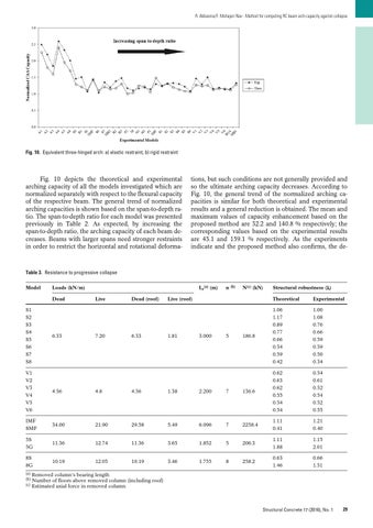
Fig. 10 depicts the theoretical and experimental arching capacity of all the models investigated which are normalized separately with respect to the flexural capacity of the respective beam. The general trend of normalized arching capacities is shown based on the span-to-depth ratio. The span-to-depth ratio for each model was presented previously in Table 2. As expected, by increasing the span-to-depth ratio, the arching capacity of each beam decreases. Beams with larger spans need stronger restraints in order to restrict the horizontal and rotational deforma-
tions, but such conditions are not generally provided and so the ultimate arching capacity decreases. According to Fig. 10, the general trend of the normalized arching capacities is similar for both theoretical and experimental results and a general reduction is obtained. The mean and maximum values of capacity enhancement based on the proposed method are 32.2 and 140.8 % respectively; the corresponding values based on the experimental results are 43.1 and 159.1 % respectively. As the experiments indicate and the proposed method also confirms, the de-
Table 3. Resistance to progressive collapse Model
Dead S1 S2 S3 S4 S5 S6 S7 S8
Lr(a) (m)
Loads (kN/m)
6.33
Live
7.20
Dead (roof)
6.33
n
(b)
N(c) (kN)
Structural robustness (λ)
Live (roof)
Theoretical
Experimental
1.81
186.8
1.06 1.17 0.89 0.77 0.66 0.54 0.59 0.42
1.00 1.08 0.76 0.66 0.59 0.59 0.50 0.34 0.54 0.61 0.52 0.54 0.52 0.55
3.000
5
V1 V2 V3 V4 V5 V6
4.56
4.8
4.56
1.38
2.200
7
136.6
0.62 0.63 0.62 0.55 0.54 0.54
IMF SMF
34.00
21.90
29.58
5.49
6.096
7
2258.4
1.11 0.41
1.21 0.40
5S 5G
11.36
12.74
11.36
3.65
1.852
5
206.3
1.11 1.88
1.15 2.01
8S 8G
10.19
12.05
10.19
3.46
1.755
8
258.2
0.63 1.46
0.66 1.51
(a) (b) (c)
Removed column’s bearing length Number of floors above removed column (including roof) Estimated axial force in removed column
Structural Concrete 17 (2016), No. 1
29