M. Classen/J. Gallwoszus · Concrete fatigue in composite dowels
The values listed for constants c1 and a were determined from the experimental results given in section 3. The comparison of the test results of a CL-shaped composite dowel with the calculated slip over the load cycles in Fig. 10 (right) illustrates the overall sufficient correlation between the model and tests.
4.3 Model for static composite dowel stiffness 4.3.1 General The static composite dowel stiffness Cstat is needed not only for understanding the evolution of inelastic slip, but also to construct the elastic branch of the cyclic dowel curve (Fig. 10, left). In the following, a numerical parametric study for the identification of relevant parameters for the dowel stiffness is first presented. Afterwards, a simple spring model is developed, allowing for an easy estimate of the dowel’s static stiffness through hand calculations.
4.3.2 Numerical investigations for composite dowel stiffness The experimental investigations of local fatigue behaviour were limited to load-dependent parameters. In order to in vestigate how geometrical and material parameters affect static dowel stiffness, finite element calculations have been performed using ABAQUS [27]. The simulation of composite dowel shear connectors has been described extensively in [28]–[31]. An identical modelling approach has been implemented in the present paper, with the normalstrength concrete being modelled by the material model “Concrete Damaged Plasticity” (CDP) [32], [33]. A stresscrack opening relationship according to [34], [35] was applied for concrete in tension (fctm = 2.5 N/mm²). The approach by Sargin [36] served as a mathematical description of the behaviour of concrete in compression (fcc = 34.8 N/mm²). All CDP parameters (Kc = 0.66, ex = 0.1, Ψ = 35°, fb0/fc0 = 1.16) used in the calculations were chosen according to the recommended values given in [27]. Stress-strain relations with elastic-plastic material behaviour and hardening in tension and compression have been used for both the structural steel (fy/fu =
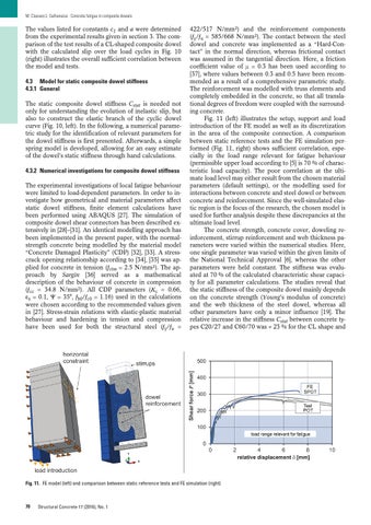
422/517 N/mm²) and the reinforcement components (fy/fu = 585/668 N/mm²). The contact between the steel dowel and concrete was implemented as a “Hard-Contact” in the normal direction, whereas frictional contact was assumed in the tangential direction. Here, a friction coefficient value of m = 0.3 has been used according to [37], where values between 0.3 and 0.5 have been recommended as a result of a comprehensive parametric study. The reinforcement was modelled with truss elements and completely embedded in the concrete, so that all translational degrees of freedom were coupled with the surround ing concrete. Fig. 11 (left) illustrates the setup, support and load introduction of the FE model as well as its discretization in the area of the composite connection. A comparison between static reference tests and the FE simulation performed (Fig. 11, right) shows sufficient correlation, especially in the load range relevant for fatigue behaviour (permissible upper load according to [5] is 70 % of characteristic load capacity). The poor correlation at the ulti mate load level may either result from the chosen material parameters (default settings), or the modelling used for interactions between concrete and steel dowel or between concrete and reinforcement. Since the well-simulated elas tic region is the focus of the research, the chosen model is used for further analysis despite these discrepancies at the ultimate load level. The concrete strength, concrete cover, doweling reinforcement, stirrup reinforcement and web thickness parameters were varied within the numerical studies. Here, one single parameter was varied within the given limits of the National Technical Approval [6], whereas the other parameters were held constant. The stiffness was evaluated at 70 % of the calculated characteristic shear capacity for all parameter calculations. The studies reveal that the static stiffness of the composite dowel mainly depends on the concrete strength (Young’s modulus of concrete) and the web thickness of the steel dowel, whereas all other parameters have only a minor influence [19]. The relative increase in the stiffness Cstat between concrete types C20/27 and C60/70 was + 23 % for the CL shape and
Fig. 11. FE model (left) and comparison between static reference tests and FE simulation (right)
70
Structural Concrete 17 (2016), No. 1