J. Wardenier/P. de Vries/G. Timmerman · Evaluation of cracks in an offshore crane runway girder
Table 1. Dimensions, steel grades and qualities of the test specimens
1
half wheel diameter
Dimension mm
Steel grade/ quality
actual fy N/mm2
900
30CrNiMo8
1000
2
rail
400w75
OX AR 360S
950
3
flange
700w75*
OX 602
500
4
web
300w65, then 30
PCD36
350
5
stiffeners
300x40; c.o.c. 900 mm
PCD36
350
*) machined to 75 mm
Table 2. Estimated number of cycles per year in the crane runway girder Wheel load (kN)
N cycles per year (16 wheels)
7700
32
7000
8
5200
400
4200
800
3300
2400
1900
104 000
Total number of cycles/year
107.640
N cycles per year in %
3.4 %
EN 1993-6 Table 5.1
EN 13001-3-1, Table C4
IIW-XIII Class 431
leff (mm)
411
350*)
350
Hoist
Wheel load
EN 1993-6 Table 5.1
EN 13001-3-1, Table C4
IIW-XIII Class 431
kN
kN
0
1900
71
84
84
2500
3300
124
145
145
96.6 % 100%
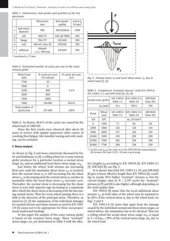
3 Stress analysis As shown in Fig. 2 and more extensively discussed by Euler and Kuhlmann in [2], a rolling wheel on a crane runway girder produces for a particular location a normal stress range )Xz and an additional local shear stress range )Yxz. Just before the wheel, both stresses are increasing from zero until the maximum shear stress Yxz is reached, then the normal stress Xz is still increasing but the shear stress Yxz is decreasing until the normal stress Xz reaches its maximum when the local shear stress Yxz becomes zero. Thereafter, the normal stress is decreasing but the shear stress is now with opposite sign increasing to a maximum after which the shear stress is decreasing with the decreasing normal stress. Thus for every wheel passing there is a shift in the direction of the principal stress. Therefore, as stated in [1], [2] the summation of the individual damages for normal stresses and shear stresses as used in EN 19931-9 [3] seems not to be appropriate for these non-proportional multi-axial loadings. In this paper the analysis of the crane runway girder is based on the nominal stress range. These “nominal” stress ranges )Xz are determined in Table 3 with the effec-
Steel Construction 10 (2017), No. 1
Table 3. Comparison “nominal stresses” with EN 1993-6, EN 13001-3-1 and IIW-XIII [4], [5], [6] Actual crane girder
Table 2. As shown, 96.6 % of the cycles are caused by the wheel load of 1900 kN. Since the first cracks were observed after about 20 years of service with regular inspection other causes of cracking then fatigue, like lamellar tearing and cold cracking, can be excluded.
68
Fig. 2. Normal stress Xz and local shear stress Yxz due to wheel load [1], [2]
)Xz (N/mm2)
5000
4200
157
185
185
10 000
5200
195
229
229
25 000
7000
262
308
308
20 000
7700
288
338
338
*) In this case leff is the same as in the IIW-XIII Recommendation [6] because the limit 0.1D f 50 mm is governing
tive lengths leff according to EN 1993-6 [4], EN 13001-3-1 [5], IIW-XIII [6], see Fig. 3. It is shown that both EN 13001-3-1 [5] and IIW-XIII [6] give a lower effective length than EN 1993-6 [4], resulting in nearly 20 % higher “nominal” stresses Xz but the current fatigue class at N " 2.106 cycles for “nominal” stresses in [5] and [6] is also higher, although depending on the weld quality class. EN 1993-6 [4] states that the local additional shear stresses Yxz at both sides of the wheel may be assumed to be 20 % of the vertical stress Xz due to the wheel load, see Figs. 3 and 4. EN 1993-1-9 [3] states that apart from the damage caused by the individual normal and shear stress ranges, as stated before, the summation has to be checked. Thus for a rolling wheel the actual shear stress range )Yxz is equal to 2 w 0.2)Xz " 40% of the vertical stress range )Xz due to the wheel load.