This Agrément relates to superbead Cavity Wall Insulation (CWI) hereinafter the “System”. The System is for use as injected CWI and improves the thermal insulation of external closed construction cavity walls with masonry inner and outer leaves (where masonry includes clay and calcium silicate bricks, concrete blocks and natural and reconstituted stone blocks) , masonry party walls or external masonry outer leaf with sheathed load-bearing timber framed stud internal walls. The System is for filling cavity walls in existing or new, residential and non-residential buildings in the UK and Ireland.
DESCRIPTION
The System is available in two variants, ‘superbead 33’ and ‘superbead 32’, offering slightly different thermal performance The System consists of a grey, spherical, closed cell, carbon enhanced expanded polystyrene (EPS) bead manufactured with a pentane expanding agent in accordance with draft BS EN 16809-1. A water-based dispersion of acrylic co-polymer emulsion, air-drying, contact bonding adhesive is simultaneously injected with the EPS beads with appropriate injection machinery. The EPS beads are coated with the bonding adhesive in the injection gun to bond and set the EPS beads and make the EPS bead fill stable over the long-term. The System is injected through a series of holes, drilled in a predetermined pattern. Layers of EPS beads are built up until the whole cavity wall is fully filled in accordance with BS EN 16809-2.
SYSTEM ILLUSTRATION
See Section 3.3 (Third-Party Acceptance). STATEMENT
It is the opinion of Kiwa Ltd. that the System is fit for its intended use, provided it is specified, installed and used in accordance with this Agrément.
Craig Devine Operations Manager, Building Products
Alpheo Mlotha CEng FIMMM MBA Business Unit Manager, Building Products
SUMMARY OF AGRÉMENT
This document provides independent information to Specifiers, building control personnel, contractors, installers and other construction industry professionals considering the fitness for the intended use of the System. This Agrément covers the following:
• Conditions of use;
• Initial Factory Production Control, Quality Management System and the Annual Verification procedure;
• Points of attention for the Specifier and examples of details;
• Installation;
• Independently assessed System characteristics and other information;
• Compliance with national Building Regulations, other regulatory requirements and Third-Party acceptance;
• Sources, including codes of practice, test and calculation reports.
MAJOR POINTS OF ASSESSMENT
Adequacy of fill - walls, including partially filled cavity walls, can be fully filled sufficiently with the System (see section 2.1.10).
Thermal insulation properties - the System improves the thermal insulation of the wall structure (see section 2.1.10).
Condensation risk - the System can contribute to limiting the risk of interstitial and surface condensation (see section 2.1.10).
Resistance to precipitation including wind-driven rain penetration - the System will resist the transfer of water across the cavity to the inner leaf (see section 2.1.10).
Resistance to ground moisture - the System does not absorb water by capillary action and may therefore be used in situations where it bridges the damp proof course (DPC) of the inner and outer leaf of cavity walls (see section 2.1.10).
Behaviour in relation to fire - the System is classified as European Classification E, in accordance with BS EN 13501-1 (see section 2.1.10).
Durability - the System is stable, rot-proof, water resistant and durable and will have a service life equivalent to that of the life of the cavity wall in which it is installed (see section 2.1.8).
CE marking - the product manufacturers have taken responsibility for CE marking of the products used in the System in accordance with all r elevant harmonised European Product Standards. An asterisk (*) appearing in this Agrément indicates that data shown is given in the relevant product manufacturer’s Declaration of Performance (DoP).
2.4 - Independently assessed System characteristics
2.5 - Ancillary items
Chapter 3 - CDM, national Building Regulations and Third-Party acceptance
3.1 - The Construction (Design and Management) Regulations 2015 and The Construction (Design and Management) Regulations (Northern Ireland) 2016
3.2 - National Building Regulations
3.3 - Third-Party acceptance
Chapter 4 - Sources
Chapter 5 - Amendment history
CHAPTER 1 - GENERAL CONSIDERATIONS
1.1 - CONDITIONS OF USE
1.1.1 Design considerations
See section 2.1.
1.1.2 Application
The assessment of the System relates to its use in accordance with this Agrément and the Agrément holder’s requirements.
1.1.3 Assessment
Kiwa Ltd. has assessed the System in combination with its relevant DoPs, test reports, technical literature and factory and site visits Factory Production Control has been assessed.
1.1.4 Installation supervision
The Agrément holder only manufactures and supplies the System. The installation companies are trained and approved by the Agrément holder.
The quality of installation and workmanship must be controlled by a competent person who shall be an employee of the installation company. Installation work shall be subject to the Kiwa Installer Assessment and Surveillance Scheme.
The System shall be installed strictly in accordance with the requirements of this Agrément.
See also section 2.1.6.
1.1.5 Geographical scope
The validity of this document is limited to England, Wales, Scotland, Northern Ireland and Ireland, with due regard to chapter 3 of this Agrément (CDM, national Building Regulations and Third-Party Acceptance).
1.1.6 Validity
The purpose of this BDA Agrément® is to provide for well-founded confidence to apply the System within the Scope described The validity of this Agrément is three years after the issue date, and as published on www.kiwa.co.uk/bda. After this, the validity of this Agrément can be extended every three years after a positive review.
1.2 - INITIAL FACTORY PRODUCTION CONTROL (FPC)
• Kiwa Ltd. has determined that the Agrément holder has fulfilled all provisions of the specifications described in this Agrément in respect of the System
• The initial FPC audit demonstrated that the Agrément holder has a satisfactory Quality Management System (QMS) and is committed to continuously improving their FPC operations.
• A detailed Production Quality Specification (PQS) has been compiled to ensure traceability and compliance under the terms of this Agrément
1.3 - QUALITY MANAGEMENT SYSTEM (QMS)
• The Agrément holder:
o has an effective and well maintained QMS in operation which covers the necessary clauses required for BDA Agrément® o is committed to continually improving their FPC, QMS and associated procedures.
• Document control and production line procedures were deemed satisfactory, with sufficient evidence provided in support of BDA Agrément® requirements.
To demonstrate that the FPC is in conformity with the requirements of the technical specification described in this Agrément, the continuous surveillance, assessment and approval of the FPC will be done at a frequency of not less than once per year by Kiwa Ltd.
2.1.1 Design responsibility
CHAPTER 2 - TECHNICAL ASSESSMENT
2.1 - POINTS OF ATTENTION TO THE SPECIFIER
The Agrément holder reviews all designs submitted and offers design advice and guidance to ensure a compliant final project s pecific design.
2.1.2 Applied building physics (heat, air moisture)
The physical behaviour of the wall incorporating the System shall be verified as suitable by a competent specialist, who can be either a qualified employee of the Agrément holder or a qualified consultant. The Specialist will check the physical behaviour of the external wall design and if necessary can offer advice in respect of improvements to achieve the final specification. A condensation risk analysis shall be completed at design stage in accordance with BS 5250. It is recommended that the Specialist co-operates closely with the Agrément holder
2.1.3 General design considerations
The System may be used in walls up to 12 m in height (or above where the Agrément holder has issued a suitable waiver), in non- residential buildings or when installed in a cavity construction comprising two masonry leaves, each at least 75 mm thick, subject to reaction to fire height restrictions in accordance with national Building Regulations
Consideration shall be given to the local wind-driven rain index in accordance with BS 8104 and the site exposure zone in accordance with PD 6697 The System shall not be used in areas of very severe exposure to wind-driven rain where fair-faced masonry is the external cladding
For masonry walls, minimum cavity widths to be filled:
• for existing buildings must be no less than 40 mm;
• for new buildings must comply with the relevant national Building Regulations;
• on new buildings where additional third-party requirements apply, the minimum cavity width may be greater
For timber framed walls:
• the minimum cavity width to be filled must be no less than 50 mm;
• the 50 mm cavity between the inner face of the external masonry wall and outer face of the timber framed inner leaf must be free from any obstruction (including insulation) to ensure that there is not a bridge that allows water to cross the cavity from the external masonry wall to the timber framed inner leaf
A lapped and sealed waterproof membrane must be applied to the outer face of the timber framed inner leaf, to further prevent risk of water exposure to the timber;
• the timber framed wall stud cavity will typically be in either 400 mm or 600 mm wide sections between solid timber studs or joists, with a typical void depth of 140 mm;
• timber framed walls may have a separate service cavity for electrical wiring, however electrical cables may be laid in the same cavity as the System. Where this is the case, careful consideration should be given to ensure that electrical wiring must be installed in conduit to separate it from the System and allow easier access for future work;
• a vapour control layer (hereinafter ‘VCL’) must be applied on the internal face of the timber framed inner leaf to ensure that the moisture content of the timber is kept at or below 20 %, and to ensure the air tightness of the building.
2.1.4 Project specific design considerations
Pre-installation survey requirements
A pre-installation survey must be undertaken to the Agrément holder’s specification; it is a mandatory requirement to use a tape measure and borescope, to assess the width of the cavity and to ensure a clear void exists. The findings of this survey must be recorded on a surveyor’s report. Selection of an appropriate drilling pattern must take into consideration the nature of the building and its construction.
2.1.5 Permitted applications
Only applications designed according to this Agrément are allowed, in each case the Specifier must cooperate closely with the Agrément holder.
Existing buildings:
• the System shall be specified to comply with the requirements of the national Building Regulations
New buildings:
• external masonry walls shall be constructed in accordance with the national Building Regulations;
• where required, due consideration must be given to any relevant third-party requirements;
• installation of the System must not be undertaken until the cavity is weathertight, i.e. the roof is in place and the window and door openings are sealed.
Partial fill (residual cavities and omitted areas); wherever practicable and possible, all of the cavity space from ground level to the roof or gable copings should be filled, with the exception of:
• when a semi-detached or terraced property is to be insulated separately. In this case a polypropylene cavity brush must be inserted at the line dividing the properties to contain the insulation. This brush is left in place upon completion of the works;
• when filling up to the underside of a horizontal boundary other than the roof, where the boundary is protected by a cavity tray or similar waterproof barrier;
• where the wall to be insulated is covered by a waterproof cladding, such as hung tiles, and this cladding either extends up to the roof or is protected at the top by other means (such a window cills);
• insulating areas of the wall where access for drilling may be limited by features such as carports and conservatories. These areas may however be accessed using the energystore thermal lance;
Third-parties may not accept external masonry walls constructed with different types of cavity insulation within the wall build up. Installing blown insulation to newly completed homes may invalidate claims made against the new home warranty.
2.1.6 Installer competence level
The Agrément holder operates an Approved Installer Scheme for the System under which installers are approved, registered and regularly reviewed by the Agrément holder to demonstrate that they are competent to carry out installations of the System in accordance with this Agrément. Details of Approved Installers are available from the Agrément holder. Approved Installers are fully responsible for each installation of the System that they undertake. Furthermore, installers are to be monitored under an Independent 3rd Party CWI Installation Assessment & Surveillance Scheme operated or approved by Kiwa Ltd.
2.1.7 Delivery, storage and site handling
See section 2.3
2.1.8 Durability
Once installed, the System is protected in service from agents liable to cause deterioration and will be effective as insulation for the life of the building in which it is installed. If it is deemed necessary for any reason, the System can be extracted from the cavity void
2.1.9 Maintenance and repair
Once installed strictly in accordance with the requirements of this Agrément, the System is contained within the structure of the wall and therefore does not require maintenance for as long as the wall is maintained in a weathertight condition.
2.1.10 Performance factors in relation to the Major Points of Assessment
Adequacy of fill (using specified installation machinery and drilling pattern)
A cavity wall can be fully filled (with no gaps and a consistent density) with the System Even the most difficult to fill area of a cavity wall (the area to be located over a conservatory where no drilling or injection is permitted) can be filled sufficiently with the System when using the energystore thermal lance installation equipment and technique. The b onding adhesive ensures that the System remains stable within the cavity and has adequate resistance to settlement.
Thermal insulation properties
For the purpose of U-value calculations and to determine if the requirements of national Building Regulations are met, the thermal resistance and U- value of cavity walls incorporating the System should be calculated in accordance with BS EN ISO 10211 (taking into consideration BS EN ISO 6946, BS EN ISO 10456, BRE Report 443, PAS 2030 and PAS 2035), using the System’s declared thermal conductivity (λD) value.
Condensation risk
External walls incorporating the System will adequately limit the risk of surface and interstitial condensation when designed in accordance with BS 5250.
Resistance to precipitation including wind-driven rain penetration
A cavity wall incorporating the System, when installed in accordance with this Agrément, can adequately resist rain water penetration across the cavity to the inner leaf. The System does not add to the risk of water penetration. The gaps that naturally occur between the EPS beads allow any water to drain down freely to the ground, rather than track across the cavity.
Resistance to ground moisture
The System does not absorb water by capillary action. Tests confirm the System will not transmit moisture by capillary action across the cavity or from below damp-proof course (DPC) level. The System can be used in situations where it bridges the DPC of the inner and outer leaf. Dampness from the ground will not pass through to the inner leaf provided the wall is correctly detailed in accordance with the requirements of the national Building Regulations.
Behaviour in relation to fire
The System is classified as European Classification E in accordance with BS EN 13501-1.
The following restrictions apply, however, refer to the national Building Regulations for types of buildings and any exclusions that may apply:
• for all building in Wales and Northern Ireland, and non-residential buildings in England, the System shall not be used on buildings with a storey of 18 m or more above ground level; the System can be used without any boundary restrictions;
• for residential buildings in England, the System is restricted to buildings with no floor more than 11 m above ground level; the System can be used without any boundary restrictions;
• for all buildings in Scotland, the System is restricted to buildings with no floor more than 11 m above ground level ; the System can be used without any boundary restrictions;
• for dwellings in Ireland, the System shall not be used on buildings with a storey of 15 m or more above ground level; the Sys tem can be used without any boundary restrictions;
• for buildings other than dwellings in Ireland, the System shall not be used on buildings with a storey of 18 m or more above ground level; the System can be used without any boundary restrictions.
The restrictions outlined above in terms of height above ground level and proximity to boundary do not apply, provided the Sy stem is installed in a cavity construction comprising two masonry leaves, each at least 75 mm thick, and with cavities closed around openings in a wall and at the top of a wall head
The System installed in a wall comprising 12 mm thick OSB board, membrane, timber studs and noggins and 12 5 mm thick plasterboard has been tested in a loadbearing timber framed wall and achieved REI 30 (see Section 2.4.6).
To ensure that the fire integrity of a timber framed wall is maintained, the timber lining board must have the joints between the boards fully sealed and supported by timber studwork or battens.
In all constructions, cavity barriers shall be provided to comply with the relevant provisions of the national Building Regul ations.
For detailed conditions of use regarding requirements for substrate fire performance, cavity closers and barriers, fire stopping of service penetrations and combustibility limitations for other materials and components used in the overall wall construction, designers shall refer to the relevant national Building Regulations.
Proximity of flues and appliances
The installed System shall be adequately separated from any chimney, heat producing appliance or incinerator flue pipe passing through a wall. Recommended means of separation are detailed in the Approved Documents supporting the national Building Regulations. 2.2
- EXAMPLES OF DETAILS
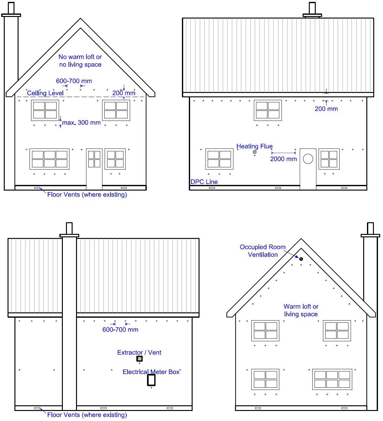
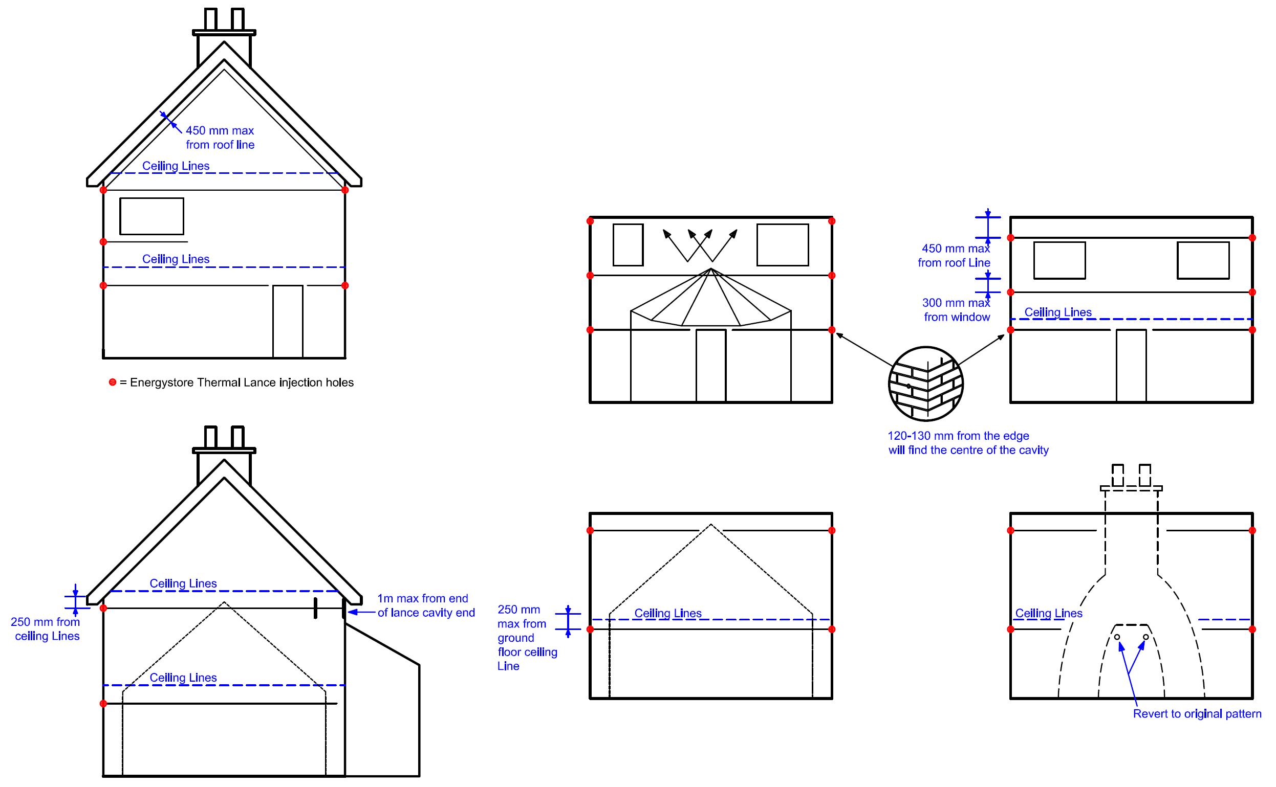
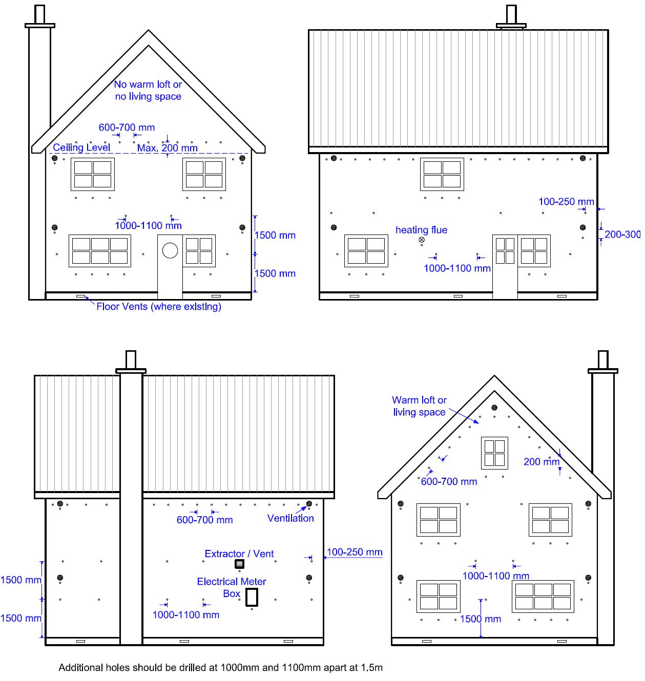
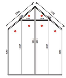
Figure 1 - Full fill drill pattern for masonry properties
Figure 2 - energystore thermal lance in masonry properties
Figure
Figure 4 - Partial fill drill pattern for masonry properties
2.3.1 Installer competence level
The Agrément holder only manufactures and supplies the System.
2.3 - INSTALLATION
The System shall be installed strictly in accordance with the System Manual instructions of the Agrément holder and the requirements of this Agrément.
Installation can be undertaken by operatives trained and approved by the installing contractor (who must belong to the Kiwa Installer Assessment and Surveillance Scheme)
2.3.2 Delivery, storage and site handling
The EPS beads:
• are delivered to site in large bulk container loads or polythene bags and labelled with the System name, Agrément holder’s name and the BDA Agrément® logo incorporating the number of this Agrément. The EPS bead is otherwise unprotected;
• should be kept dry and away from heat sources and avoid rain exposure and protected from prolonged exposure to sunlight.
Damaged, contaminated or wet materials must not be used.
The bonding adhesive:
• is delivered to site in plastic drums/containers and labelled with the System name, Agrément holder’s name and the BDA Agrément® logo incorporating the number of this Agrément;
• has an optional ‘winter mix’ adhesive available which has a flow additive to assist in cold temperatures;
• containers should be stored inside and off the ground at a temperature between 5 °C and 25 °C and protected from frost, direct sunlight and high temperatures.
2.3.3 General procedure
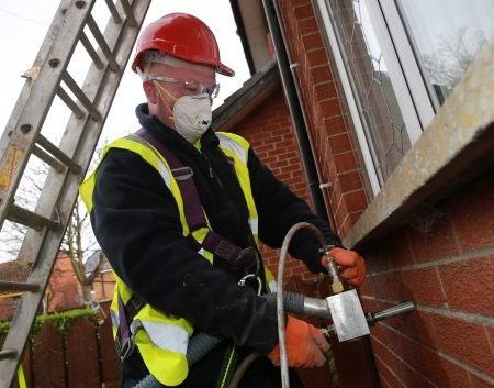
Installation of the System is undertaken using injection machines based on a compressed air delivery system. The installer provides all necessary hoses, drilling tools, equipment, injection gun and materials for making good the walls after the installation.
Whenever practicable and possible, all of the cavity space from ground level to the roof or gable copings should be filled. Installation must be carried out to the highest point in each elevation, or to a level determined by any vertical cavity barrier between adjacent properties (whichever is the lower).
The target mean installed density of this System is 12 kg/m3 over the entire wall. Local areas within the wall must not have a density variation of more than ± 2 kg/m3 from the target mean density over an area of 0.5 m2
Application of the System is to be left until the cavity is weather-tight, i.e. that the external masonry wall and roof is in place and that all cavity openings, such as those around doors and windows, are sealed, to avoid water ingress on to the System.
2.3.4 Preparation
Typical preparatory works include:
• repairs to pointing, if required;
• repairs to the timber framed wall, if required;
• sleeving or otherwise modifying essential vents to prevent blockage by installation of the System;
• temporary sealing of window and door openings;
• temporary sealing of all uncapped cavity walls;
• provision of a cavity tray, stop ends and weep holes at lintel level;
• removal of any debris or mortar droppings left in the cavity;
• sealing of defects in the openings in the inner or outer leaf of walls especially electricity and gas meter boxes using appropriate material;
• insertion of a cavity brush at the line dividing semi-detached or terraced properties to permanently contain the System
2.3.5 Standard fill method
Masonry drilling operation:
• depending on the injection gun being used for application, 22 mm or 26 mm diameter injection clearance holes are drilled into the mortar joints in the outer leaf at the point where the vertical mortar joint meets the horizontal mortar bed.
Masonry drilling pattern:
• the recommended drilling patterns are illustrated in Figure 1 and also given in writing and as diagrams in the System Manual for typical situations that can be met in practice;
• additional drill holes may be required to ensure complete filling around building features, e.g. under window cills, around air bricks, in column areas between doors and windows, at the tops of walls and under gables. Care should be taken to ensure that drill holes do not coincide with any intermediate suspended timber floor.
In order to prevent debris falling onto the insulation, all drilling must be completed on one elevation and at least 2 m of the adjoining elevations before injection commences on that elevation. Each elevation is filled only after completing all the drilling required in that elevation
Timber frame drilling operation:
• core (over-drill) holes must be 75 mm
Timber frame drilling pattern:
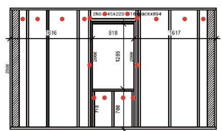
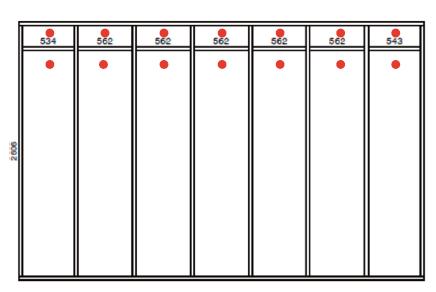
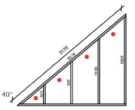
• the recommended drilling patterns are illustrated in writing and as diagrams in the System Manual for typical situations that can be met in practice;
• core (over-drill) holes must pass only through the plasterboard;
• a maximum 22 mm slit is cut in the VCL in the centre of the 75 mm core (over-drill) hole;
• core (over-drill) holes must be horizontal;
• care must be taken not to cause damage to the timber framed wall
Pre-filling checks
For masonry walls:
• borescope inspections must be carried out to verify the existence of clear cavities and to identify any services within the cavity.
For timber framed walls:
• a 360 ° borescope check should be carried out in every void being filled to ensure that the timber framed wall has been built in line with the specification drawings;
• the borescope check should be completed using the drill holes to minimize the number of holes drilled in the internal plasterboard;
• filling can commence once the installer is satisfied that the timber framed wall has been built to specification, wiring is encased in conduit and location of the drill hole is suitable.
Checks are carried out to determine the injection machine settings are optimised, including:
• a pressure switch test which ensures that the injection machine pressure switch is operating correctly;
• EPS bead and adhesive flow rate check which ensures that the System will be injected into the cavity with the correct amount of adhesive being applied for the volume of EPS beads recorded at the desired EPS bead density.
Injection filling
For masonry walls:
The System is injected into the cavity under pressure through the drill holes via a flexible pipe, fitted with a directional injection nozzle. The EPS beads pack to a uniform density in the cavity. The System should be injected into each drill hole in turn. Filling should proceed from the bottom row of drill holes to the top of the walls and working across from side to side or from the most to the least restricted areas, ensuring a complete and even fill.
See Figure 1 and the System Manual for further detail in respect of this procedure.
For timber framed walls:
• injection of the System should be carried out prior to plastering of the internal face of the timber framed wall, so that the voids can be clearly identified by the visible location of fasteners in intermediate studs.
The voids within the timber framed wall are injected with the System using a directional nozzle to prevent damage to the plasterboard
See Figure 5 and the System Manual for further detail in respect of this procedure.
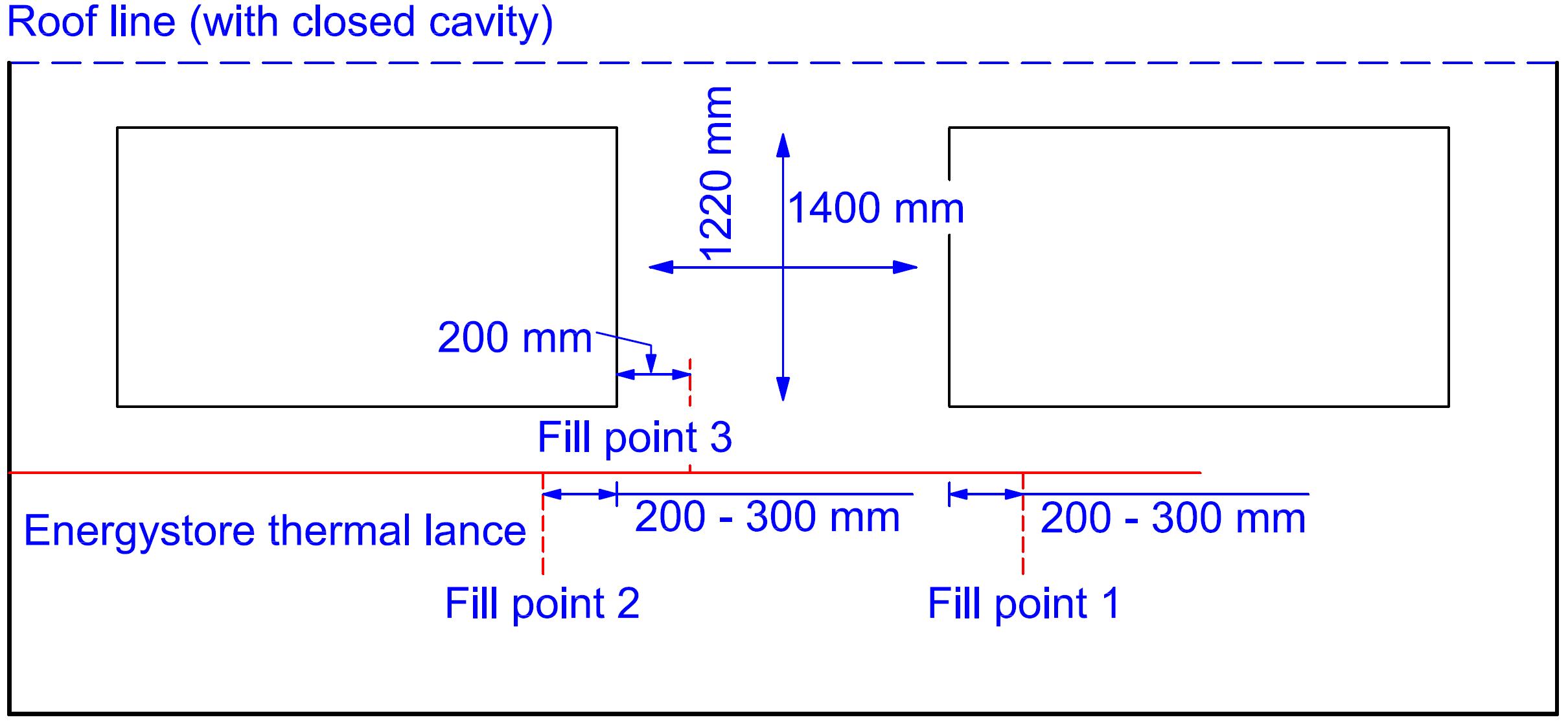
The energystore thermal lance is used to install hard to reach areas such as above conservatories or car ports, up to 8 m from end of walls. The energystore thermal lance can enable the System to be installed from the corners of properties if required.
See Figures 2 and 3, and the System Manual for further detail on this procedure.
2.3.7 Partial fill option method - masonry walls
The partial fill method is used to top up pre-insulated cavity walls.
See Figure 4 and the System Manual for further detail on this procedure.
2.3.8 Finishing
Masonry walls:
• the drill holes are fully filled with mortar of a similar colour, texture and weathertightness to that of the existing wall.
See the System Manual for further detail on this procedure.
Timber framed walls:
• the VCL is repaired and the original core is replaced using a drywall repair clip. The core is then covered with adhesive scrim prior to plastering.
See the System Manual for further detail on this procedure.
2.3.9 Post-installation checks
Post-installation external and internal checks are carried out to ensure:
• that the installation has been completed and that no dama ge has occurred to the building;
• all areas have been insulated;
• all the external drill holes have been sealed with mortar or render; check all internal drill holes in timber framed walls are finished as per section 2.3.8;
• all areas including trunked air vents, e.g. those providing under -floor ventilation and combustion air for heating appliances, are checked and any obstructions or EPS bead ingress must be cleared and the cavity breach sealed if possible;
• all flues and chimneys must be carefully checked by an appropriate test (e.g. a smoke test) to verify that they are clear and unobstructed;
• EPS beads injected through the top of the cavity into the loft space are removed and any points of leakage sealed;
• eaves in the loft are left free from EPS beads to facilitate airflow;
• all electric circuits and appliances have been reinstated.
2.4 - INDEPENDENTLY ASSESSED SYSTEM CHARACTERISTICS
2.4.1 Adequacy of fill of injected CWI (using specified installation machinery and drilling pattern)
The filling of cavity walls with the System has been witnessed in-situ during site visits, including:
• the use of the energystore thermal lance to fill a cavity of a gable wall;
• the correct drilling pattern and accuracy;
• the recommended distances between drill holes and distance above joist level;
• correct injection technique being used
The filling has also been examined in a test rig, showing a cavity can be sufficiently fully filled with the System. After installing, no voids were visible in the cavity.
2.4.2 Bead size and density
Test Result
Bead size diameter by passing samples through a graded series of sieves
Installed target mean apparent density to BS EN 16809-2 and BS EN 1602
2.4.3 Thermal insulation properties
Test
The installed System has declared thermal conductivity (λ90/90) to BS EN ISO 10456 and BS EN 12667
2.4.4 Water vapour transmission
Test
Loose-fill EPS beads have a water vapour resistance factor µ to BS EN 12524 2
2.4.5 Water absorption
Test
Short-term water absorption (24 hr) by partial immersion to BS EN 1609, method A, 40 mm thickness, 23 °C, 50 % rh WS (value does not exceed 1.0 kg/m 2)
2.4.6 Behaviour in relation to fire
Test
Reaction to fire classification to BS EN 13501-1
Fire behaviour of a load bearing timber stud wall, while under load (5.5 kN per stud)
Test
Fire resistance classification of above wall make-up to BS EN 13501-2
^ Tested wall construction 12 mm thick OSB board, membrane, timber studs and noggins (140 x 39 mm), superbead injected bonded bead cavity wall insulation, membrane, 12.5 mm thick plasterboard
2.5 - ANCILLARY ITEMS
Ancillary items detailed in this section may be used in conjunction with the System but fall outside the scope of this Agrément:
• finishing mortar or render;
• timber framed wall finishing materials.
3.1 - THE CONSTRUCTION (DESIGN AND MANAGEMENT) REGULATIONS 2015 AND THE CONSTRUCTION (DESIGN AND MANAGEMENT) REGULATIONS (NORTHERN IRELAND) 2016
Information in this Agrément may assist the client, Principal Designer/CDM co-ordinator, designer and contractors to address their obligations under these Regulations.
3.2
- NATIONAL BUILDING REGULATIONS
In the opinion of Kiwa Ltd., the System, if installed and used in accordance with Chapter 2 of this Agrément, can satisfy or contribute to satisfying the relevant requirements of the following national Building Regulations.
3.2.1 - ENGLAND REQUIREMENTS: THE BUILDING REGULATIONS 2010 AND SUBSEQUENT AMENDMENTS
• B3(1) Internal fire spread (structure) - the System does not prejudice the stability of walls
• B3(4) Internal fire spread (structure) - a wall incorporating the System can inhibit the unseen spread of fire and smoke within concealed spaces
• C2(a) Resistance to ground moisture - the System does not absorb water by capillary action and may therefore be used in situations where it bridges the damp proof course (DPC) of the inner and outer leaf
• C2(b) Resistance to precipitation moisture - a wall incorporating the System can resist rain penetration to the inner leaf and satisfy this Requirement
• C2(c) Resistance to condensation moisture - the System can contribute to satisfying this Requirement
• J4 Protection of building - the System can be separated from heat producing appliances, flue pipes, chimneys and fireplaces to prevent a building from catching fire
• L1(a)(i) Conservation of fuel and power - the System can contribute to limiting heat gains and losses through a wall
• Regulation 7(1) - Materials and workmanship - the System is manufactured from suitably safe and durable materials for its’ application and can be installed to give a satisfactory performance
• Regulation 23 - Requirements relating to thermal elements - use of the System can contribute to the conservation of fuel and power in buildings by limiting heat gains and losses through thermal elements and other parts of the building fabric
• Regulation 26 - CO2 emission rates for new buildings - the System can contribute to satisfying this Requirement
• Regulation 26A - Fabric energy efficiency rates for new dwellings - the System can contribute to satisfying this Requirement
• Regulation 26C Target primary energy rates for new buildings - the System can contribute to satisfying this Requirement
3.2.2 - WALES
REQUIREMENTS: THE BUILDING REGULATIONS 2010 AND SUBSEQUENT AMENDMENTS
• B3(1) Internal fire spread (structure) - the System does not prejudice the stability of walls
• B3(4) Internal fire spread (structure) - a wall incorporating the System can inhibit the unseen spread of fire and smoke within concealed spaces
• C2(a) Resistance to ground moisture - the System does not absorb water by capillary action and may therefore be used in situations where it bridges the damp proof course (DPC) of the inner and outer leaf
• C2(b) Resistance to precipitation moisture - a wall incorporating the System can resist rain penetration to the inner leaf and satisfy this Requirement.
• C2(c) Resistance to condensation moisture - the System can contribute to satisfying this Requirement
• J4 Protection of building - the System can be separated from heat producing appliances, flue pipes, chimneys and fireplaces to prevent a building from catching fire
• L1(a)(i) Conservation of fuel and power - the System can contribute to limiting heat gains and losses through a wall
• Regulation 7(1) Materials and workmanship - the System is manufactured from suitably safe and durable materials for its’ application and can be installed to give a satisfactory performance
• Regulation 23 - Requirements relating to thermal elements - use of the System can contribute to the conservation of fuel and power in buildings by limiting heat gains and losses through thermal elements and other parts of the building fabric
• Regulation 26 - CO2 emission rates for new buildings - the System can contribute to satisfying this Requirement
• Regulation 26A - Primary energy rates for new buildings - the System can contribute to satisfying this Regulation
• Regulation 26B - Fabric performance values for new dwellings - the System can contribute to satisfying this Requirement
• Regulation 26C Minimum energy efficiency rating - the System can contribute to satisfying this Requirement
3.2.3 - SCOTLAND
REQUIREMENTS: THE BUILDING (SCOTLAND) REGULATIONS 2004 AND SUBSEQUENT AMENDMENTS
3.2.3.1 Regulation 8 (1)(2) Fitness and durability of materials and workmanship
• The System is manufactured from acceptable materials and is considered to be adequately resistant to deterioration and wear under normal service conditions, provided it is installed in accordance with the requirements of this Agrément
3.2.3.2 Regulation 9 Building Standards - Construction
• 2.1 Compartmentation - a wall incorporating the System can inhibit the spread of fire and smoke
• 2.3 Structural protection - the System does not prejudice the load-bearing capacity of walls
• 2.4 Cavities - a wall incorporating the System can inhibit the unseen spread of fire and smoke within concealed spaces
• 3.4 Moisture from the ground - the System can contribute to a construction satisfying this standard with reference to clause 3.4.1 of the Technical Handbooks; the System can be used in situations where it bridges the DPC of the inner and outer leaf
• 3.10 Precipitation - the external leaf of a cavity wall prevents precipitation from reaching the inner leaf of the wall by allowing water to drain down the resultant cavity; the System does not inhibit this action
• 3.15 Condensation - a wall incorporating the System can be designed and constructed to inhibit condensation
• 3.19 Combustion appliances - the System can be separated from heat producing appliances, flue pipes, chimneys and fireplaces to prevent a building from catching fire
• 6.2 Building insulation envelope - a wall incorporating the System can reduce heat loss
• 7.1(a)(b) Statement of sustainability - the System is manufactured from materials that can contribute to satisfying the relevant requirements of Regulation 9, Standards 1 to 6, and therefore will contribute to a construction meeting a bronze level of sustainability as defined in this Standard; in addition, the System can contribute to a construction meeting a higher level of sustainability as defined in this Standard
3.2.3.3 Regulation 12 Building Standards - Conversion
• All comments given under Regulation 9 also apply to this regulation, with reference to Schedule 6 of The Building (Scotland) Regulations 2004 and subsequent amendments, clause 0.12 of the Technical Handbook (Domestic) and clause 0.12 of the Technical handbook (Non- Domestic)
3.2.4 - NORTHERN IRELAND REQUIREMENTS:
• 23(1)(a)(i)(iii)(b) Fitness of materials and workmanship - the System is manufactured from materials which are considered to be suitably safe and acceptable for use as described in this Agrément
• 28(a) Resistance to ground moisture - the System can contribute to satisfying this Regulation
• 28(b) Resistance to the weather - a wall protects the System from precipitation to the inner face
• 29 Condensation - a wall shall be designed and constructed to prevent interstitial condensation
• 35(1) Internal fire spread - Structure - the System does not prejudice the stability of walls
• 35(4) Internal fire spread - Structure - a wall incorporating the System can inhibit the unseen spread of fire and smoke within concealed spaces
• 39(a)(i) Conservation measures - the System can contribute to limiting heat gains and losses through a wall
• 40(2) Target carbon dioxide emission rate - a wall incorporating the System shall be designed and constructed as not to exceed its target CO2 emission rate
• 43 Renovation of thermal elements - the renovation work carried out to ensure the wall complies with requirement 39(a)(i)
• 73(1) Protection of people and buildings - the System can be separated from heat producing appliances, flue pipes, chimneys and fireplaces to prevent a building from catching fire
3.2.5 - IRELAND
REQUIREMENTS: BUILDING REGULATIONS 1997 AND SUBSEQUENT AMENDMENTS
In order to demonstrate compliance with Irish Building Regulations, this BDA Agrément® certifies that the System complies with the requirements of a recognised document and indicates it is suitable for its’ intended purpose and use.
• B3(1) Internal fire spread (structure) - the System does not prejudice the stability of walls
• B3(3) Internal fire spread (structure) - a wall incorporating the System can inhibit the unseen spread of fire and smoke within concealed spaces
• B8(1) Internal fire spread (structure) - the System does not prejudice the stability of walls
• B8(3) Internal fire spread (structure) - a wall incorporating the System can inhibit the unseen spread of fire and smoke within concealed spaces
• C4 Resistance to weather and ground moisture - a wall can prevent the passage of moisture to the inside of the building
• D1 Materials and workmanship - the System is manufactured from acceptable materials and is considered to be adequately resistant to deterioration and wear under normal service conditions, provided it is installed in accordance with the requirements of this Agrément
• J3 Protection of building - the System can be separated from heat producing appliances, flue pipes, chimneys and fireplaces to prevent a building from catching fire
• L1 Conservation of fuel and energy - the System can contribute to limiting heat gains and losses through walls and conserve fuel and energy
• L2(a) Conservation of fuel and energy (in existing dwellings) - the System can contribute to limiting heat gains and losses through walls
• L4(a) Conservation of fuel and energy (in existing buildings other than dwellings) - the System can contribute to limiting heat gains and losses through walls
• L5(c) Conservation of fuel and energy (in new buildings other than dwellings) - the System can contribute to limiting heat gains and losses through walls
• Regulation 7 Conservation of fuel and energy in existing dwellings - the System can contribute to satisfying this Requirement
• Regulation 8(c) Conservation of fuel and energy in new dwellings - the System can contribute to satisfying this Requirement
3.3 - THIRD-PARTY ACCEPTANCE
In the opinion of Kiwa Ltd. if installed, used, and maintained in accordance with this Agrément, this System can satisfy the appropriate structural, fire, moisture, thermal, acoustic and durability requirements of a Structural Warranty provider. Please contact the relevant Structural Warranty provider to ascertain their project specific design requirements and to confirm their acceptance on a case- by-case basis.
CHAPTER 4 - SOURCES
• BS EN ISO 6946:2017 Building components and building elements. Thermal resistance and thermal transmittance. Calculation methods
• BS EN ISO 10211:2017 Thermal bridges in building construction. Heat flows and surface temperatures. Detailed calculations
• BS EN ISO 10456:2007 Building materials and products. Hygrothermal properties. Tabulated design values and procedures for determining declared and design thermal values
• BS EN ISO 11925-2:2010 Reaction to fire tests. Ignitability of products subjected to direct impingement of flame. Single- flame source test
• BS EN ISO 13788:2012 Hygrothermal performance of building components and building elements. Internal surface temperature to avoid critical surface humidity and interstitial condensation. Calculation methods
• BS EN 1363-1:2020 Fire resistance tests. General requirements
• BS EN 1363-2:1999 Fire resistance tests. Alternative and additional procedures
• BS EN 1365-1:2012 Fire resistance tests for loadbearing elements. Walls
• BS EN 1602:2013 Thermal insulating products for building applications. Determination of the apparent density
• BS EN 1609:2013 Thermal insulating products for building applications. Determination of short term water absorption by partial immersion
• BS EN 12524:2000 Building materials and products. Hygrothermal properties. Tabulated design values
• BS EN 12667:2001 Thermal performance of building materials and products. Determination of thermal resistance by means of guar ded hot plate and heat flow meter methods. Products of high and medium thermal resistance
• BS EN 13172:2012 Thermal insulation products. Evaluation of conformity
• BS EN 13238:2010 Reaction to fire tests for building products. Conditioning procedures and general rules for selection of substrates
• BS EN 13501-1:2018 Fire classification of construction products and building elements - Classification using data from reaction to fire tests
• BS EN 13501-2:2016 Fire classification of construction products and building elements. Classification using data from fire resistance tests, excluding ventilation services
• BS EN 15026:2007 Hygrothermal performance of building components and building elements. Assessment of moisture transfer by numerical simulation
• Draft BS EN 16809-1. Thermal insulation products for buildings. In-situ formed products from loose-fill expanded polystyrene (EPS) beads and bonded expanded polystyrene beads. Part 1. Specification for the bonded and loose filled products before installati on
• BS EN 16809-2:2017 Thermal insulation products of buildings. In- situ formed products from loose-fill expanded polystyrene (EPS) beads and bonded expanded polystyrene beads. Specification for the bonded and loose- fill products after installation
• BS 476-21:1987 Fire tests on building materials and structures. Methods for determination of the fire resistance of loadbearing elements of construction
• BS 5250:2011+A1:2016 Code of practice for control of condensation in buildings
• BS 8104:1992 Code of practice for assessing exposure of walls to wind-driven rain
• BRE Report 443:2006 Conventions for U-value calculations
• BRE Report 497:2016 Conventions for calculating linear thermal transmittance and temperature factors
• BRE Information Paper IP 1/06:2006 Assessing the effects of thermal bridging at junctions and around openings
• BRE GBG 44-2:2000 Insulating masonry cavity walls: principal risks and guidance
• BRE GG 33:2015 Building damp-free cavity walls
• CIGA Technician’s guide to best practice:2002 Installing cavity wall insulation
• CIGA CWI - Guide to best practice:2008 Working at height in the retrofit CWI industry
• CIGA Technician’s guide to best practice:2016 Flues, chimneys and combustion air ventilators
• PAS 2030:2019+A1:2022 Specification for the installation of energy efficiency measures in existing dwellings
• PAS 2035:2019+A1:2022 Retrofitting dwellings for improved energy efficiency. Specification and guidance
• PD 6697:2019 Recommendations for the design of masonry structures to BS EN 1996-1-1 and BS EN 1996-2
Remark: apart from these sources confidential reports may also have been assessed; any relevant reports are in the possession of Kiwa Ltd and kept in the Technical Assessment File of this Agrément; the Installation Guides are current at the time of publication and may be subject to change, the Agrément holder should be contacted for clarification of revision
CHAPTER 5 - AMENDMENT HISTORY
First issue
Bead size corrected
C Re-issue following successful 3 Year Renewal
D Updated bead size
E Updated bead size
F Updates to Building Regulations and Fire Performance; Introduction of superbead 33/32 variants