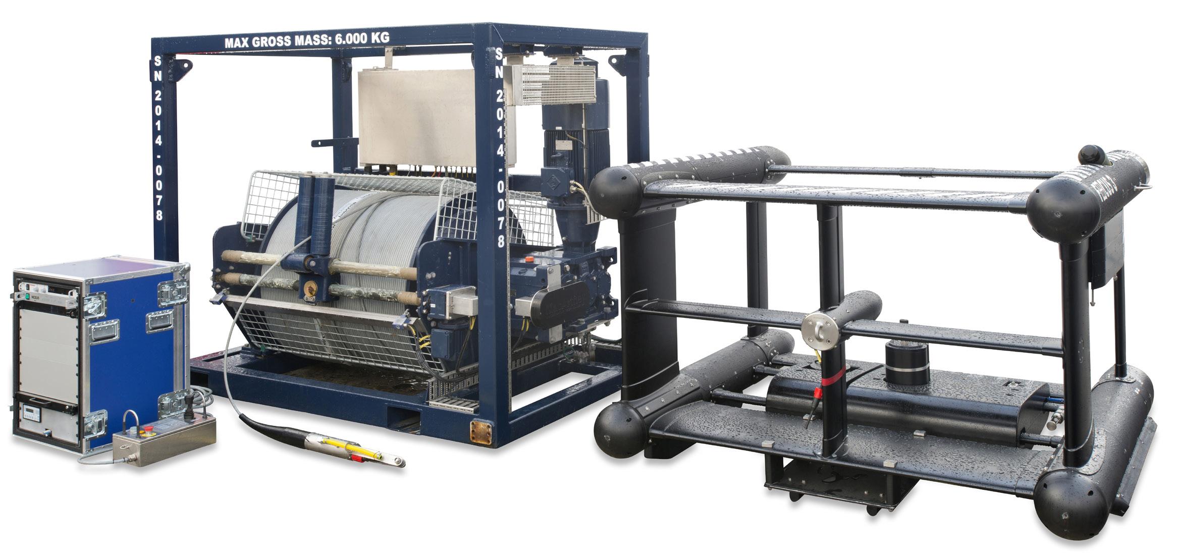
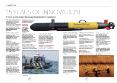
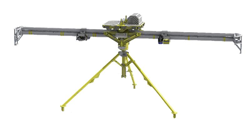
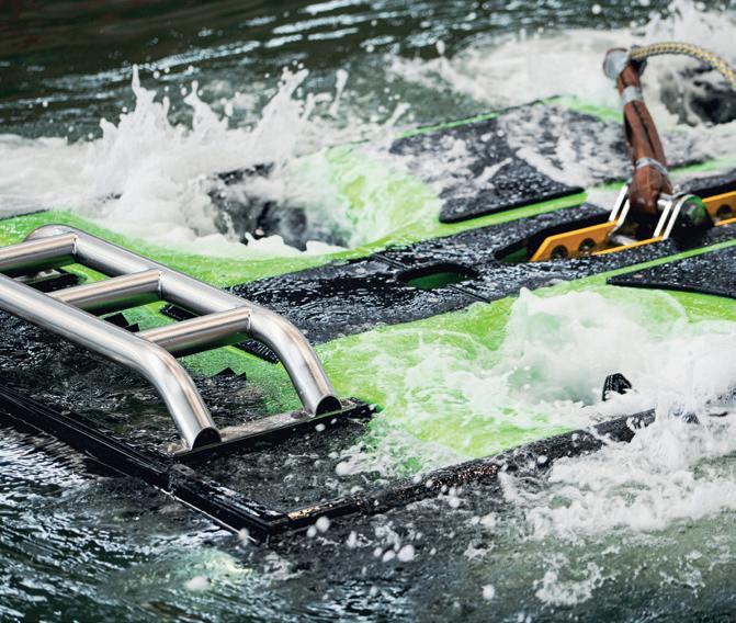
Ideal platform solution for high-precision survey applications
Powerful, low-maintenance electric winch system
Cost-effective, high-speed survey platform
Modular design
1,000 m depth rating
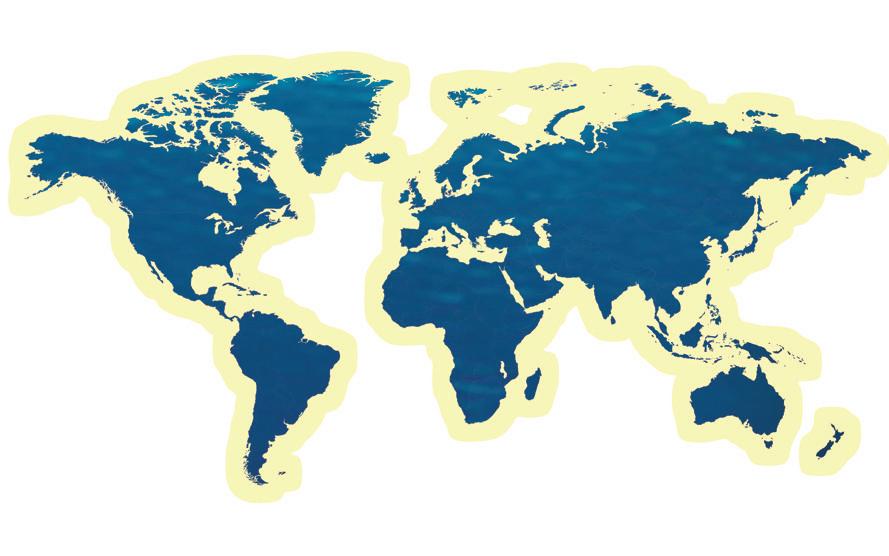
MacArtney global solutions
Flexible and high payload capacity
Vol 19 No 1
Editor: John Howes John@ut-2.com +44 7859905550
Editorial Terry Byte
Research M Hamilton Perry
Advertising: Zinat Hassan UT3subsea@gmail.com
Tel: +44 (0) 845 6522 483
Mobile: +44 (0) 781 1200 483
Published by UT2 Publishing for and on behalf of the Society for UnderwaterTechnology. Reproduction of UT2 in whole or in part, without permission, is prohibited.The publisher and the SUTassumes no responsibility for unsolicited material, nor responsibility for content of any advertisement, particularly infringement of copyrights, trademarks, intellectual property rights and patents, nor liability for misrepresentations, false or misleading statements and illustrations.These are the sole responsibility of the advertiser. Opinions of the writers are not necessarily those of the SUTor the publishers
KRAKEN CCUS
LOCATING LEGACY WELLS FOR CARBON CAPTURE
In December 2024, the Net Zero Teesside Power (NZT Power) and the Northern Endurance Partnership (NEP) CCS project reached financial close to become a world first project where a fossilfueled power station will store its CO2 safely below the seabed in a disused gas reservoir.
But where are these buried wellheads and what condition are they in? Kraken Robotics has been applying geophysical survey techniques to help provide answers.
MAGNETICS SURVEY (PASS 1)
It is likely that the actual XY location of the wellhead would differ from the recorded position by a few tens of meters due to inaccuracies in positioning and charting when these wells were drilled and abandoned. Many of wellheads have been left since the 1960s and early 1970s.
A towed magnetic survey would, therefore, be the most cost effective method of updating the XY position.
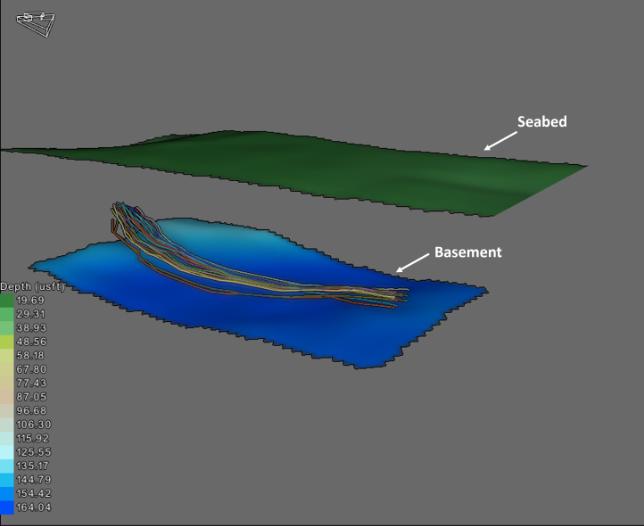
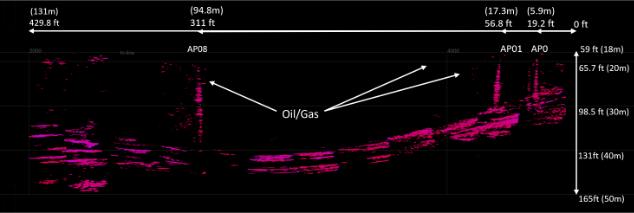
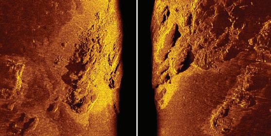
Results from a Kraken Robotics 3D Acoustic Corer survey mapping buried Conductors at depths of 140ft below the seabed. The AC was used to map the entire field, producing positions of buried infrastructure to support potential CCS and decommissioning
Towing a passive magnetic system several hundred metres slant range from the vessels USBL will not provide absolute positioning of the wellhead, but the accuracy is certainly enough to support the next stage of abandoned well assessment, a high-resolution 3D Acoustic survey.
3D ACOUSTICS SURVEY (PASS 2)
Next stage is to assess exact XY and Z location in addition to conditional assessment. For this, an ideal tool is Kraken Robotics' Acoustic Corer (AC). This provides a 14m wide, >30m deep 3D acoustic volume below the seabed.
Given the system is static on the seabed, USBL positioning is more accurate and can be further improved upon by using LBL arrays, providing the most accurate subsea position of a buried well head available.
Kraken Robotics Acoustic Corer in it's deployed state and booms locked in place. The AC has three acoustic transducer Packages and hydrophones per boom.
Equipped with a high, low and parametric chirp projector, the system images in 3D below the seabed, mapping changes in acoustic impedance ie, changes from one lithology to another,
Subsea Test Tools
discrete anomalies such as buried boulders, or, in this case, man made infrastructure in the form of vertical well heads.
The seabed context is of particular importance when it comes to identifying the actual wellhead over, say, items of metallic debris surrounding the well, caused by explosive cutting. So, the ability to identify a discrete anomaly over a continuous structure is an important factor to consider.
Centred on the updated magnetic position, the survey design will provide three AC scans, each capturing the well position in a Triple Venn pattern.
By imaging the well in three separate scans, the AC confirms sub-seabed position, removes any acoustic blanking caused by the asset, provides 360° acoustic imagery and, once merged into a seamless 3D volume, increases the signal to noise ratio of
the data set making interpretation and data review much clearer.
Positions of infrastructure mapped, the acoustic data can also perform a final integrity check of well heads and pipelines, by locating any leaking hydrocarbons into the sediment or water column.
For infield pipelines which are typically buried <5m below the seabed, Kraken’s Sub-Bottom Imager is typically used, mobilised to an ROV, but for deeper-buried
assets and well heads, the AC provides the increased penetration needed.
The AC data is transferred to the vessel live, meaning the buried well head can be plotted whilst the AC is stationary on the seabed and the exact position logged.
Once the wellhead position is known sub seabed, a marker is placed on top, enabling future excavation and reentry works to be conducted accurately, referenced to the acoustic survey data results.
Amplitude plot of Acoustic Corer data showing deep-buried conductors (horizontal linear features) with seeping hydrocarbons, identified by the vertical ascent through the sediment to the seabed
SHOM DRIX
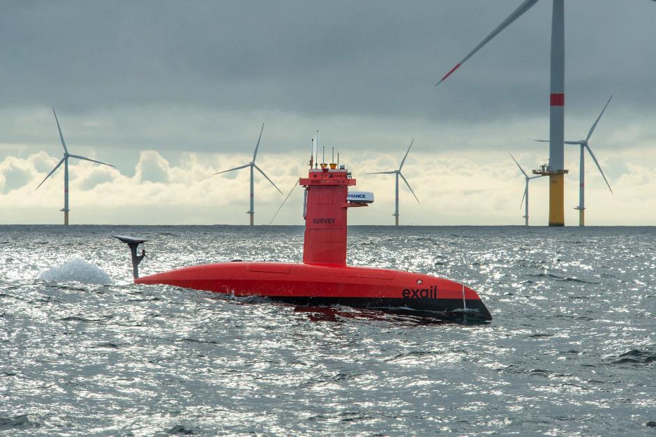
The Shom (French Naval Hydrographic and Oceanographic Service) has confirmed the acquisition of a DriX H-8, the surface hydrographic drone, developed by the French company Exail.
This acquisition marks a strategic milestone in the modernisation of Shom’s capabilities, addressing the growing demand for reliable and certified marine data for both civilian and military purposes.
The DriX H-8 will be deployed for diverse hydrographic tasks, including seabed topography, wreck detection and seabed composition analysis. It will also play a key role in preliminary studies for offshore wind farm development.
The collected data will enhance understanding of the marine environment while expanding intervention capabilities over increasingly extensive areas,
including deep-sea regions. The DriX H-8 is positioned as a strategic asset for faster, betterinformed decision-making.
Designed to operate 24/7, the DriX H-8 delivers highly accurate hydrographic surveys through innovative engineering that minimises disturbances and optimises data quality, even in challenging conditions.
These capabilities were validated during trials conducted by Shom aboard the hydro-oceanographic vessel (BHO) Beautemps-Beaupré off the French coast of Brest in 2020 and in the Gulf of Lion in 2023.
During these trials, the DriX H-8 demonstrated its effectiveness in demanding maritime environments, confirming its ability to deliver reliable data and outperform traditional hydrographic survey vessels.
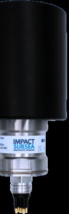
IMPACT
Impact Subsea has launched its newest sensor, the ISP360 Profiling Sonar with IS3 Impact Subsea Signalling Scheme.
The ISP360 is a high-performance profiling sonar that sets a new standard in measurement precision and range capability.
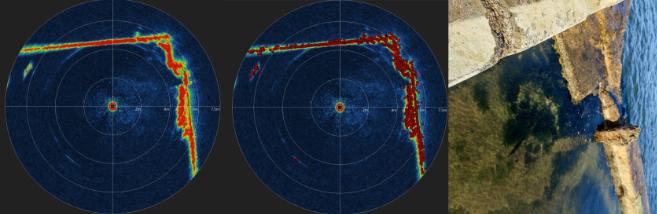
A highly compact and power efficient 1deg profiling sonar, with up to 80m range and a 0.35mm timing resolution. The ISP360 provides sonar imagery with profiler points overlaid on top of this. Each point can then be logged or output to a survey package to enable the creation of a 3D points cloud.
Acoustically the ISP360 can operate over the frequency range of 650kHz to 1.25MHz using Continuous Wave (CW), Compressed High Intensity Radar Pulse (CHIRP) or the Impact
DriX H-8
Working under high pressure
DeRegt delivers
Taking connections to a deeper level
Working in oceanic depths under great pressure requires cables and connections you can rely on. At DeRegt Cables we provide outstanding technical solutions and custom-engineered cable solutions for the most challenging of circumstances. When you are raising the bar, we deliver the right solution.
• Top notch cable design
• Reliable cable manufacturing
• High end cable termination
• Thorough cable testing
• Outstanding field service
Call us for the best connection +31 180 66 88 00
Feel free to reach out and connect
Zaag 2-4, 2931 LD Krimpen aan de Lek, The Netherlands info@deregtcables.com | deregtcables.com
Subsea Signaling Scheme (IS3).
IS3 Impact Subsea Signalling Scheme uses advanced phase modulation and coding techniques to provide exceptional signal integrity, timing accuracy and range resolution.
IS3 provides the range resolution
benefits of CHIRP acoustics but without the angular distortion inherent in CHIRP signalling.
Critically IS3 also allows multiple ISP360 profilers to operate with minimised interference. This removes the requirement for ‘ping syncing’ traditionally required for multiple mechanically scanned profilers – enabling much faster scanning capability when using multiple profilers and thus decreased survey times.
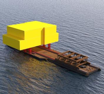
FLOATOVER
Heerema Marine Contractors has signed a contract with TenneT for the delivery of a new float-over barge, tailored to install the more than 30 000 t 2GW Offshore Substations (OSS) which is crucial for the expansion of the Dutch and German electricity grids.
Image data, image data with profiler points overlaid and photo of profiled pool corner
Left: Profiling Sonar
Floatover barge
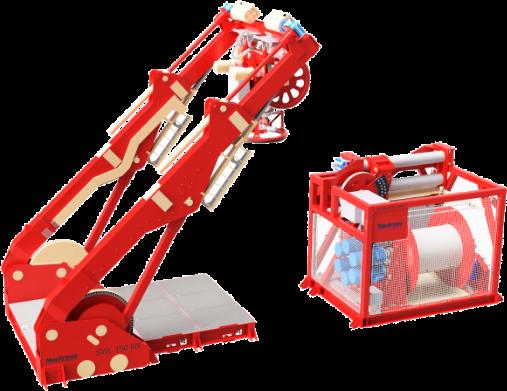
ALLSEAS eLARS
Allseas has commissioned MacArtney to enhance and future-proof its ROV operations. This involves replacing three existing hydraulic launch and recovery systems with the all-electric eLARS.
Seeking to transition from hydraulic to next-generation electric launch and recovery systems (LARS), Allseas identified MacArtney's eLARS as the optimal solution. The eLARS incorporates several advanced technologies that offer operational and environmental benefits.
The scope comprises three over-the-side 150 kN allelectric A-frames, including docking head and AHC winch, for a new fleet of electric remotely operated vehicles (ROVs) used in survey and construction tasks to water depths of 4-6km.
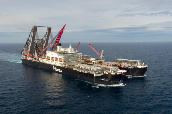
One system is planned to be mobilised on Allseas' Pioneering Spirit, the largest, most versatile offshore construction vessel in the world; others are planned to be mobilised on the dynamically positioned pipelay vessels Solitaire and Lorelay
INNOVATION OVER TRADITIONAL SYSTEMS
In its standard configuration, eLARS fully complies with Allseas' requirements, meeting key design specifications such as high deck deployment, enhanced safety for crew and equipment, and recovery redundancy from maximum operating depths
ENHANCING RELIABILITY THROUGH SMART TECHNOLOGY
The eLARS offers a low environmental impact, real-time diagnostics, high efficiency, automated launch and recovery, and intelligent, upgradable control systems that ensure longevity and versatility. Its streamlined design optimises deck space and supports green practices by eliminating pressurised oil contamination over water.
It incorporates high redundancy and intelligent self-assessment for preventive maintenance, reducing costs by up to 50% compared to hydraulic systems. Operable from shore, it requires fewer crew on board and reduces crew exchange expenses.
Along with online troubleshooting, these features ensure continuous operation, less downtime, and optimised resource use, improving planning and scheduling.
Additionally, OPEX is lowered thanks to cost-efficient spares with minimal lead times, minimal customisation, simplified installation and quicker turnaround times due to standardised components.
Pioneering Spirit
15 YEARS OF INNOVATION
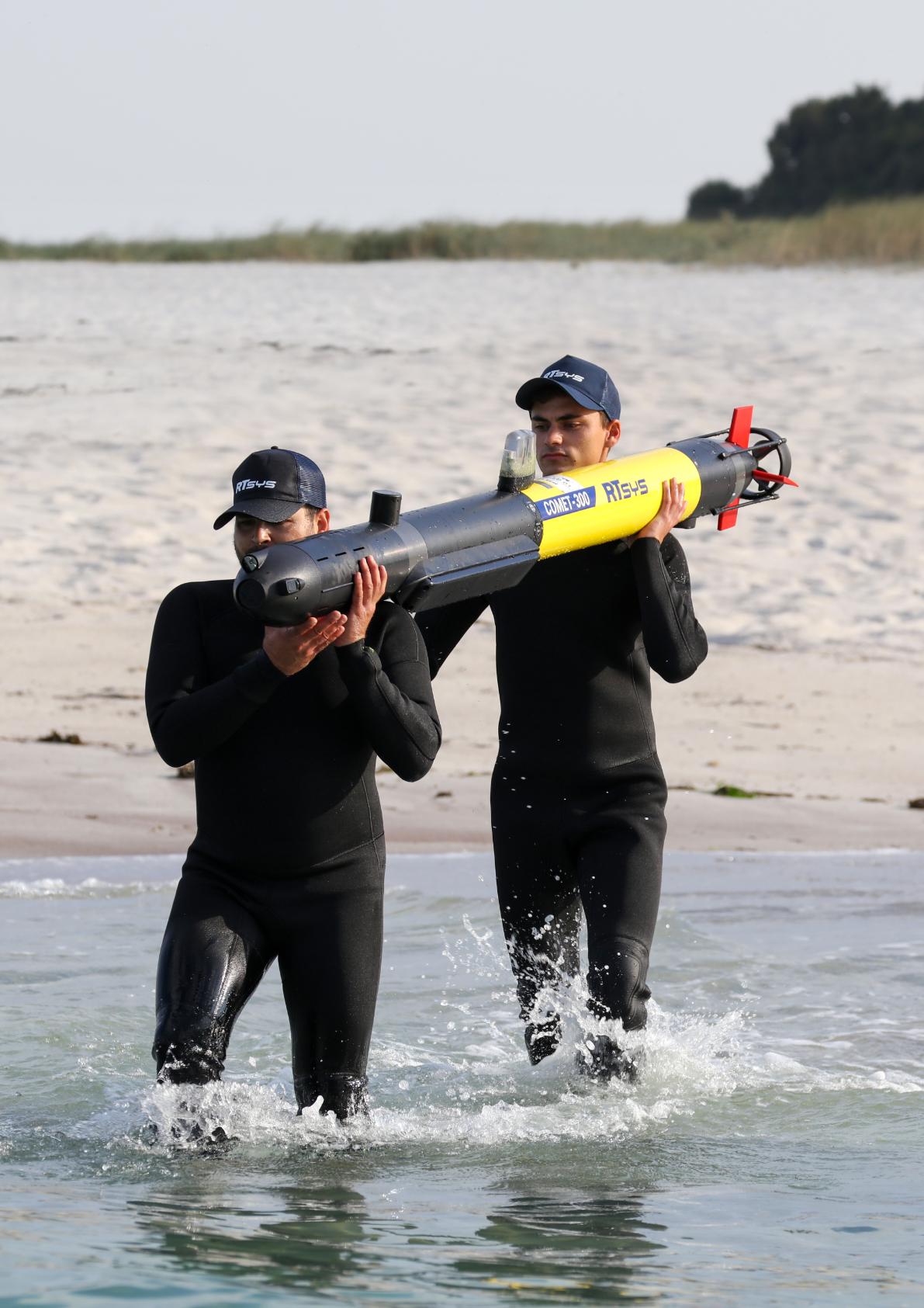
RTSYS AUVS REDEFINE UNDERWATER EXPLORATION
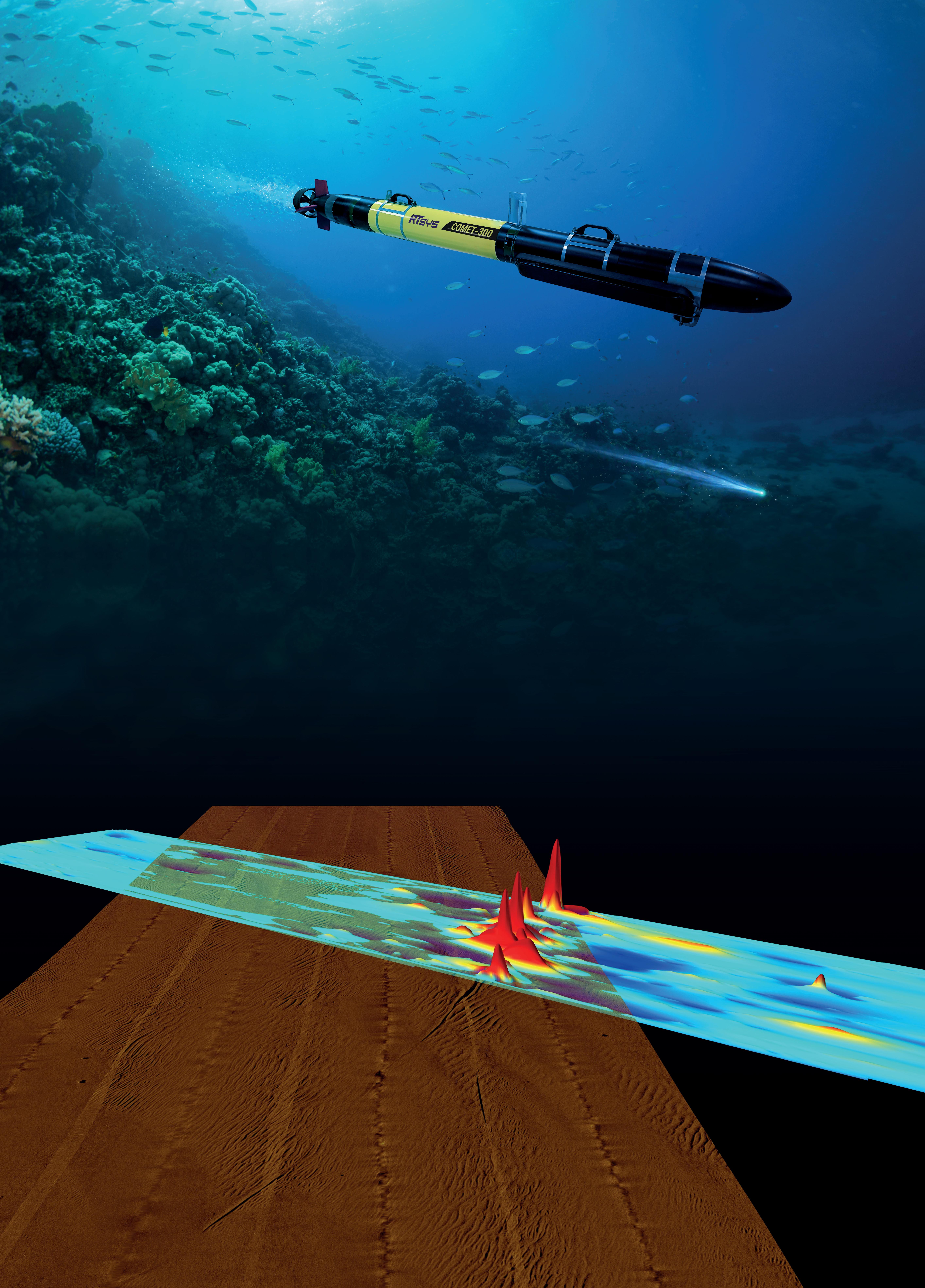
In the rapidly evolving domain of ocean technology, RTsys has emerged as a pioneer with its advanced autonomous underwater vehicles, COMET-300 and NemoSens. These AUVs have set new benchmarks in underwater exploration, environmental monitoring, and defence applications.
Innovative design, superior performance and operational flexibility make them indispensable tools for various stakeholders from marine scientists to naval forces.
COMET-300
COMET-300 is a highperformance AUV designed for extended missions requiring precise navigation, robust payload integration and reliable data acquisition. With a sleek hydrodynamic design, COMET300 is optimised for operations up to depths of 300m.
It has an operational range of over 20hrs, making it ideal for long-distance surveys. It is equipped with state-of-the-art INS (Inertial Navigation System), DVL (Doppler Velocity Log), GPS and Sparse-LBL embedded integration, which ensures pinpoint accuracy even in challenging environments.
It has a wide range of modular configurations, enabling integration of side-scan sonar, magnetometer, TV camera and lights, environmental sensors, and custom instruments. Thanks to its compact form factor, its
deployment and recovery is straightforward, reducing operational downtime.
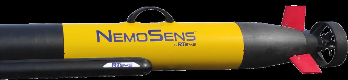
NEMOSENS
NemoSens is RTsys’ micro AUV designed for missions requiring high manoeuvrability and rapid deployment. Despite its small size, NemoSens delivers exceptional performance, addressing the needs of both research institutions and commercial operators, as well as EOD departments and Special Operations Forces.
It has a wide variety of payload options, including side-scan sonar, magnetometer, TV camera and lights, and acoustic payload among others. Its affordable price point opens up opportunities for institutions with limited budgets to access cutting-edge ocean technology.
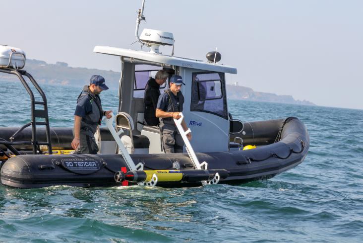
It has a compact design. Weighing less than 10 kg, it is easily deployable by a single operator, even from small vessels.
TECHNOLOGICAL INNOVATIONS
Both AUVs incorporate RTsys’ proprietary highly energy-efficient
INNOVATION
propulsion systems, that enable longer operational durations. The battery technology employed ensures rapid charging and long lifecycle, reducing mission costs over time.
RTsys’ legacy in underwater acoustics is evident in the COMET-300 and NemoSens architectures.
Both models feature acoustic data transfer which is a reliable proprietary underwater communication and real-time data exchange system from the AUVs to the surface (and surface to AUVs).
Multiple AUVs can operate in coordinated swarms, enabling wide-area data collection and complex mission execution.
A standout feature embedded in all RTsys AUVs is the RACAM (Remote And Communication Acoustic Modem) protocol. This proprietary protocol enhances operational efficiency and situational awareness by:
• Enabling robust and secure acoustic communication even in challenging underwater environments.
• Allowing real-time monitoring of the AUV's status, including position, sensor data, and mission progress.
• Facilitating dynamic reprogramming of missions while the AUV is submerged, providing unparalleled flexibility during operations.
• Enabling data synchronisation with surface systems, minimising post-mission processing time.
APPLICATIONS
Marine researchers and environmental agencies can leverage the capabilities of these
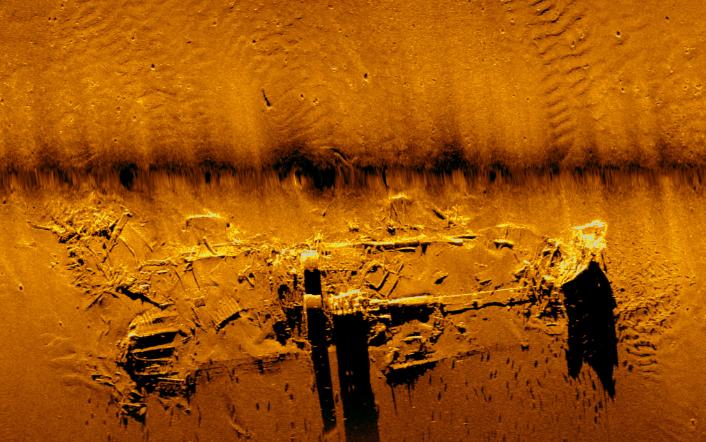
AUVs for tasks such as seafloor mapping: (high-resolution bathymetric surveys using interferometric side scan sonar), marine ecosystem studies (such as monitoring biodiversity, water quality, and sediment composition), and climate change analysis – collecting data on ocean temperature, salinity, and acidification to study climate impacts.
In defence applications, COMET300 and NemoSens have proven critical in mine countermeasures (MCM) by detecting and classifying underwater mines with high accuracy.
Sonar image from the AUV
Another application is maritime awareness, conducting stealth reconnaissance missions in hostile waters and asset protection: guarding critical infrastructure such as harbours up to undersea cables and pipelines.
Industries such as offshore energy and telecommunications benefit from these AUVs in areas including pipeline inspection: detailed imaging and analysis of subsea pipelines and structures.
They can be used in renewable energy projects when supporting the installation and maintenance of offshore wind farms (in addition to PAM activities, another RTsys specialty) as well as mapping underwater mineral deposits and hydrocarbon reserves.
The affordability and user-friendly design of RTsys AUVs make highend oceanographic tools accessible to any institution, fostering innovation in developing regions.
The modular approach of both AUVs also ensures that users can customise the platforms to meet specific needs without incurring excessive costs.
The swarm capability of both COMET-300 and NemoSens enable collaborative missions, where multiple units work together to cover large areas quickly and efficiently.
This scalability is particularly beneficial search & rescue operation or on the other hand for environmental disaster response, such as oil spill assessments or tracking harmful algal blooms.
SUSTAINABILITY
RTsys prioritises sustainability, ensuring their AUVs have a minimal environmental footprint. Quiet propulsion systems reduce disturbances to marine life, aligning with global efforts to preserve underwater ecosystems.
RTsys also offers global support and after-sales services. Their team provide expert guidance with comprehensive training programs and 24/7worldwide technical assistance for troubleshooting and maintenance as well as fast delivery of spare parts and efficient repair services to minimise downtime.
The company can also offer tailored upgrades and modifications based on user feedback and evolving needs.
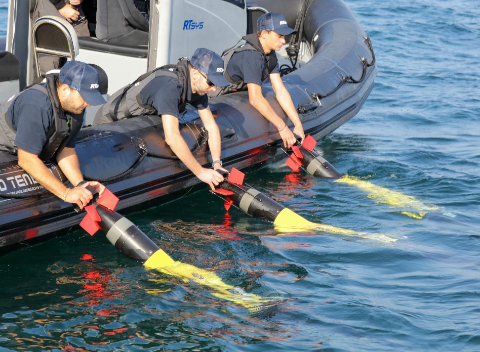
AUV Launching from a boat
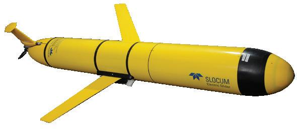
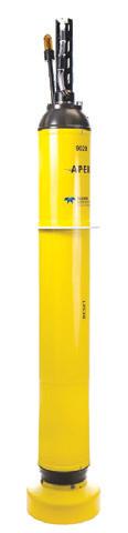
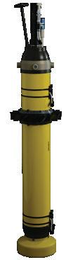
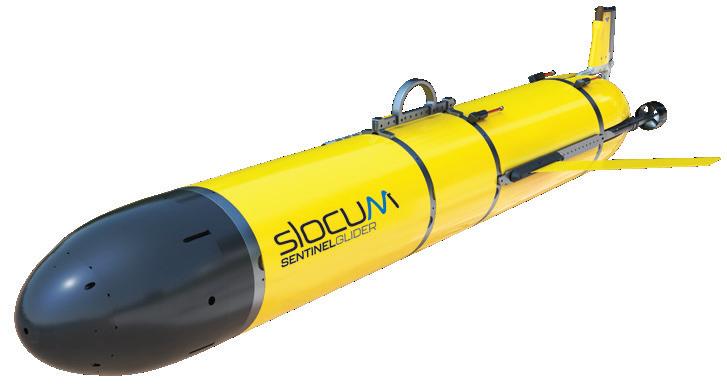
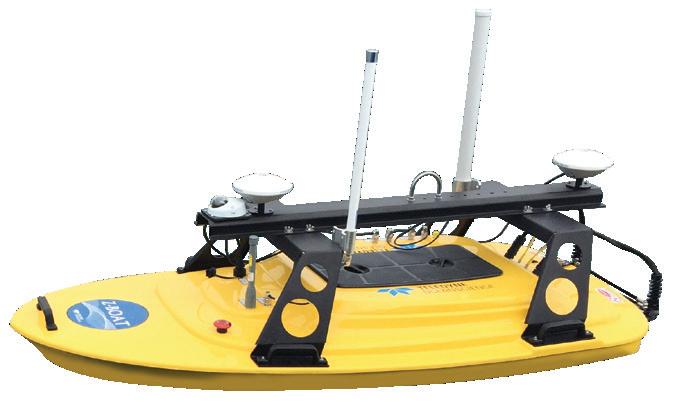
Teledyne Marine manufactures a wide selection of uncrewed vehicles operating throughout the water column from the surface to the seafloor, including shallow and deepwater modular AUV’s for military, commercial and scientific applications, Oceanscience USVs capable of carrying an array of survey instrumentation along with Slocum autonomous underwater gliders and APEX profiling floats for long duration and persistent oceanographic research and environmental monitoring.
Our Passion Runs Deep
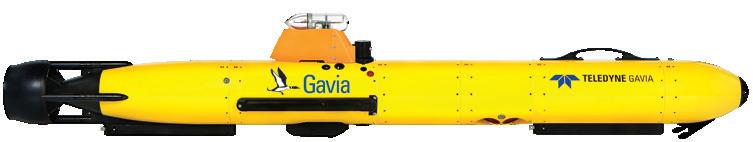
Gavia AUV
APEX Floats
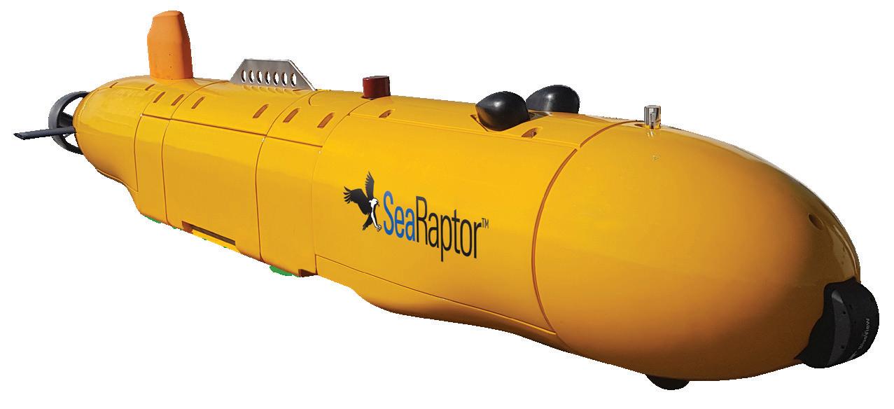
SeaRaptor AUV
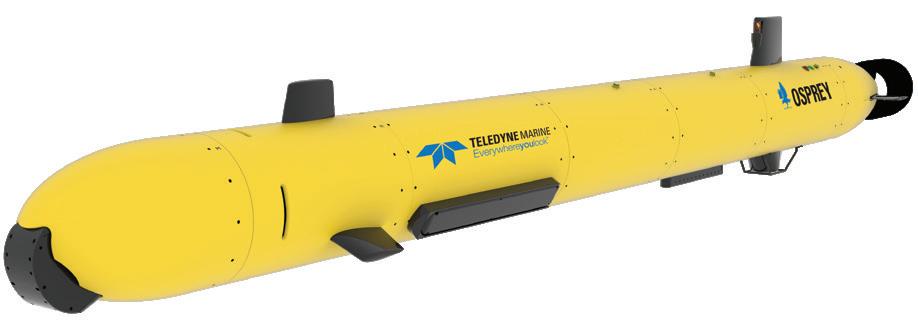
Osprey AUV
Slocum G3 Glider
Ultra Long Endurance Glider
Z-Boat
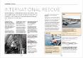
INTERNATIONAL
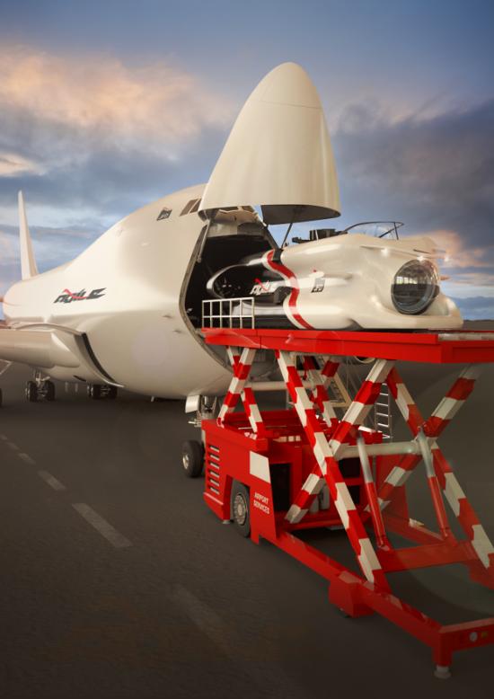
WHAT HAPPENS IF A SUBMARINE FAILS WHILE OPERATIONAL, AND IS UNABLE TO MOVE. HOW WOULD THE CREW, POSSIBLY UP TO 50, ESCAPE? THIS HAS PROMPTED THE DEVELOPMENT OF PURPOSEBUILT EMERGENCY ESCAPE CRAFT.
By John Howes
Last September, NATO embarked on the Dynamic Monarch 24 submarine rescue exercise in Norwegian territorial waters. Held every three years, Dynamic Monarch brings together naval forces from across the Alliance to test and refine their submarine rescue capabilities.
Dynamic Monarch generally alternates between warm and cold water although this year’s exercise in Norway was the first cold water iteration since 2014. It involved 10 nations – Canada, France, Germany, the Netherlands, Norway, Poland, Sweden, Türkiye, the United Kingdom and the United States.
Exercise planners developed complex scenarios to reflect realworld situations submariners might face. Exercise Dynamic Monarch 24 involved NATO’s International Submarine Rescue Liaison Office (ISMERLO), which enhances cooperation between Allies and Partners for submarine rescue. ISMERLO is based at
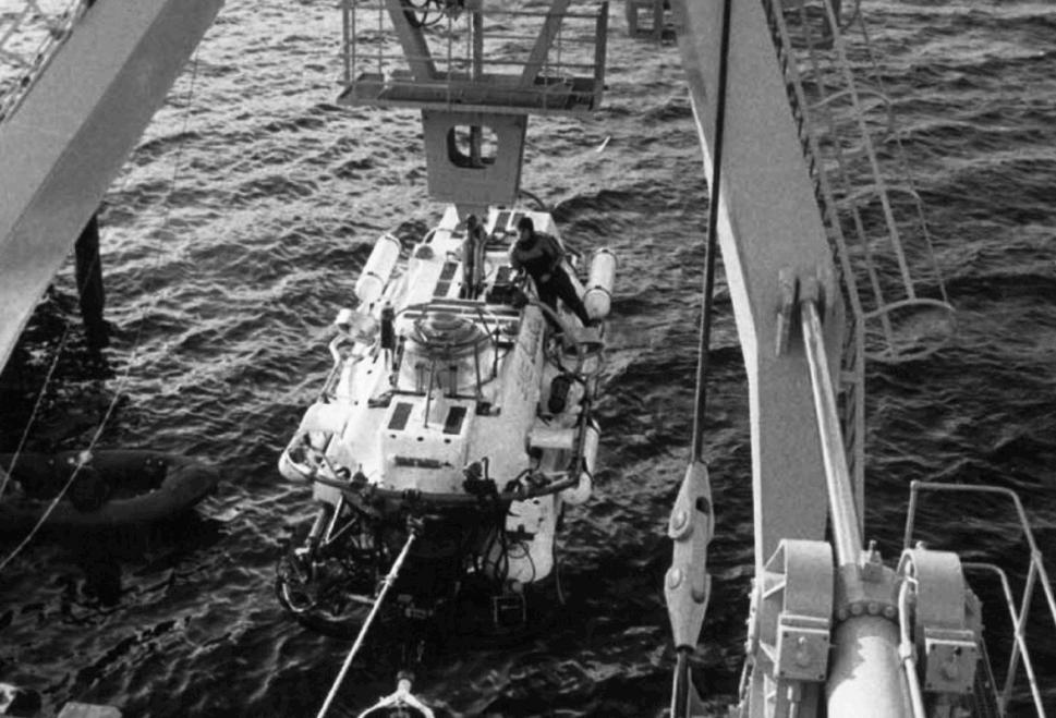
Pisces III submersible
RESCUE
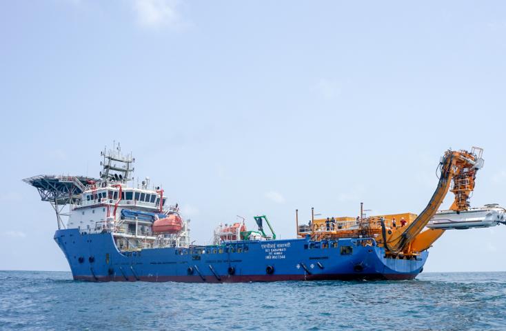
INDIA
Currently, the Indian Navy' operates two Deep Submergence Rescue Vehicles, one for the eastern and one for the western seaboard,
both adaptable for ship mounting or air transport. They are capable of operating at depths of 650 m.
HISTORY
NATO HQ Allied Maritime Command (MARCOM) in Northwood, UK.
Responding to the challenge, State-of-the-art rescue ships NoCGV Barentshav (Norway), HMSwS Belos (Sweden) and TCG Alemdar (Türkiye) took part, deploying specialist equipment. Part of the exercise involved the NATO Submarine Rescue System (NSRS).
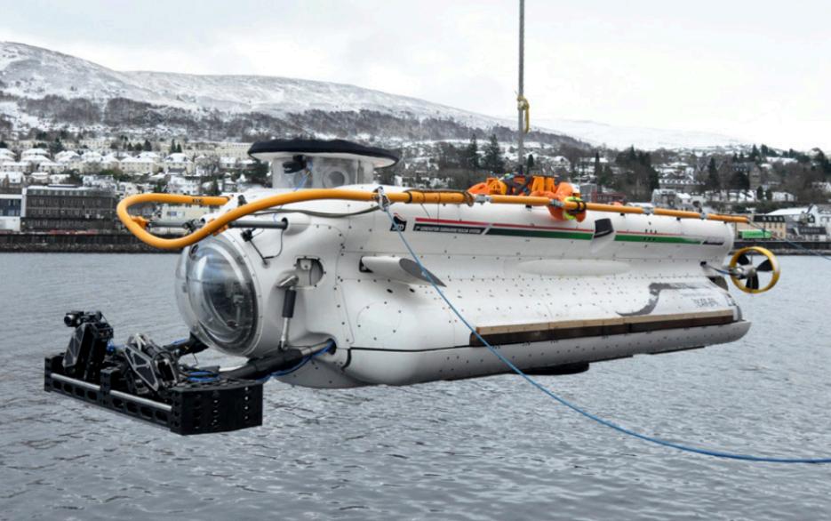
Jointly owned by France, Norway and the UK, it is based at HM Naval Base Clyde but operating teams aim to have it anywhere in the world within 96 hours.
These represent the most advanced rescue systems of a service that dates back to the 1930s when the first rudimentary systems first started to appear.
It was in 1973, however, that the importance of a coordinated multinational rescue effort became news.
Roger Chapman and Roger Mallinson were recovered from their Pisces III submersible after more than 76 hours trapped on the seabed, with fewer than 20 minutes of life support remaining. Their rescue was the first of its kind and, at 480m,
SUBMARINE RESCUE
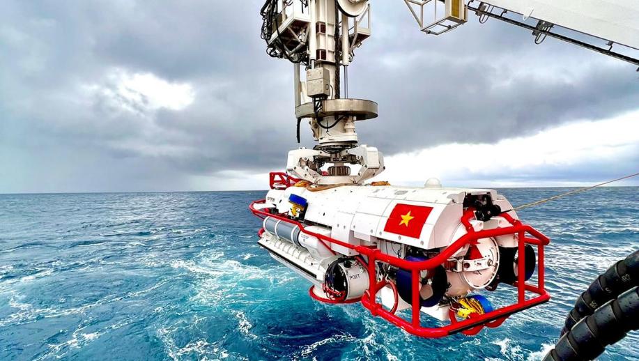
VIETNAM
In 2022, a new deep-diving submersible was delivered to the Vietnam People's Navy. It is capable of rescuing up to 17 people at a time and operating at depths of up to 600m.
remains the deepest ever performed.
Chapman would go on to dedicate his life to the safety of those who spend their lives subsea by founding Rumic, a company that would eventually become James Fisher Defence (JFD), today, a major player in the submarine rescue area.
The early submarine rescue chambers essentially consisted
The 10m by 3.2m SRV can move at speeds of up to four knots and attach itself to submarines listing at angles above 40 deg. Vietnamese rescue. Image FET
of a column that was lowered down from the surface onto the stricken submarine. This would lock onto a submarine hatch to create an airtight seal, allowing the Submarine inhabitants to transfer into its internal body.
This model is still used today, but there are also larger and more advanced vehicle designs that can be steered in real time onto the stricken submarine and allow a people to be transferred in a
single move, with some containing hospital facilities, however, more both vehicles ostensibly perform the same operation.
SUBSUNK
A typical rescue operation commences when authorities receive a SUBSUNK alert – a notification that a submarine is in distress ( itself sometimes referred to as DISSUB).
If communication was lost, operators would know roughly where the last transmission was received, but this might necessitate a preliminary survey, possibly using AUVs or ship-based sonar as part of a general search to pinpoint its specific location.
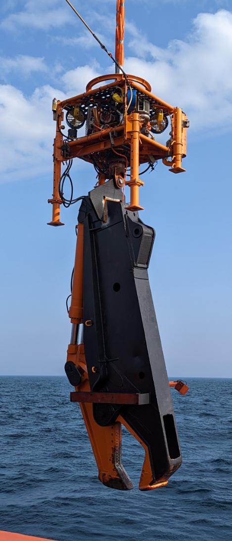
“It might be, for example, that the submarine simply got caught in fish netting or ropes, and all that is needed for a vehicle to release the submarine is by cutting jaws at the end of a manipulator arm," said Commercial manager at FET Subsea, Chris Buckle.
"Alternatively, it might be something more debilitating and so the first action would be to carry out an external survey while determining the attitude of the submarine. It might be on its side
- something rare but not impossible. It might be partially. sunk in mud.
"This 'first response' vehicle should be powerful enough to carry a variety of tools to assist in removing debris.
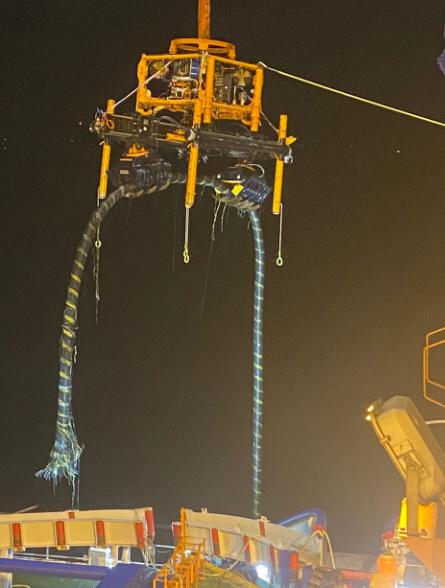
“We use a version of our proven commercial ROV's that have been employed in offshore support for many Decades. Useful properties of any ROV would be variable vectored thrusting and being capable of operating in depths of 1000m.
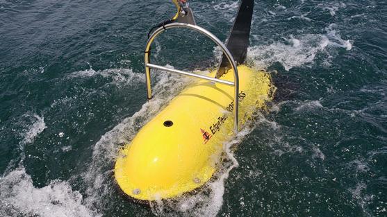
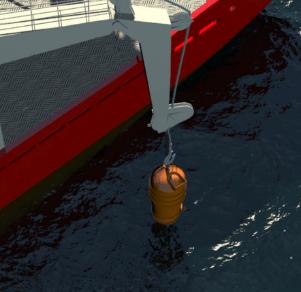
"One thing that may be required is the delivery of emergency life support stores (ELSS). These watertight pods can be posted. through the submarine's escape rescue hatch. They contain life-
preserving stores that the crew can rely on until a full rescue can be mounted.
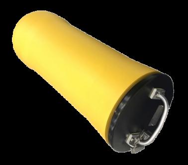
"A typical ELSS pod is nominally 10 kg and is negatively buoyant in seawater, which in addition to the ROV, enables it to be delivered to the submarine by a someone in an Atmospheric Diving Suit (ADS)." Each ELSS container comprises a cylindrical pressure vessel with a removable end cap fitted with a lifting handle. The payload can be varied using a combination of ballast weights, which keep the weight in water of the container constant.
The cylindrical pressure vessel is manufactured from aluminium and coated with yellow Xylan, which is both tough and resilient to impact during deck handling
SOUTH KOREA
In 2021, Daewoo Shipbuilding launched its next-generation submarine rescue ship.
The 120m long rescue ship ROKS
Ganghwado incorporates a moon pool which allows it to launch the DSRV in harsher surface conditions than from a stern-mounted Aframe.
The ELSS pod weighs around 10 kg
and deployment. A pressure equalising valve ensures that the cylinder is not under or overpressurised before being opened.
"Another tool that can be used is the Ventilation and
Depressurization System (VDS) Connection Tool." said Buckle.
"The ROV can plug in large 23in hoses into the submarine's STANAG connectors to purge out any bad air replacing with fresh."
"Generally, rescue submersibles would have 12 hours of oxygen for a typical mission profile plus 96 hours emergency supply as specified by the classification societies," continued Buckle.
RESCUE VEHICLES
A number of types of deep submergence rescue vehicle have been developed.
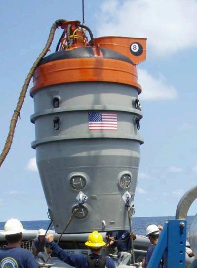
One of the most elementary, but nonetheless effective is a Submarine Rescue Chambers (SRC). Modern systems are an evolution of the 1939 the McCann Rescue Chamber which successfully rescued thirty-three survivors from the Squalus
These have the lowest cost and smallest footprint submarine rescue system available.
Because of their small size and lightweight, they have the instant advantage that they can be can be rapidly transported In operation, an ROV attaches a down-haul cable to a special pad-
eye on the submarine hatch in order to align itself and mate. The crew enter the top of this large quasicylindrical structure, to operate the controls.
The entire chamber is then lowered down to the submarine, where the articulating skirt at the base connect to the deck, allowing the crew to exit through the hatch and into the escape vehicle.
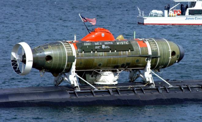
By the 1970s the US Navy were looking for a replacement and designed the Mystic and Avalon, two fibreglass vessels rated for 1500m that could position travel to the submarine under their own power and whole station within an inch of the target.
Submarine Rescue Chamber (SRC)
API17F certified
SUBMARINE RESCUE
By 2006, this was replaced by the remotely controlled Submarine Rescue Diving Recompression System (SRDRS). Its PRM (Pressurised Rescue Module) FALCON, was deemed faster to deploy.
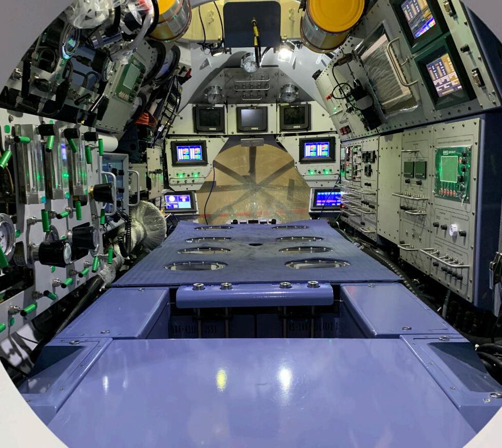
Right The Mystic Below Inside the LEII Command module Image: FET
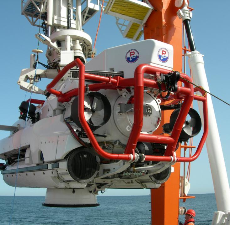
NATO SRV, 610m rated and manufactured by FET
TRANSFER UNDER PRESSURE
One of the keys to submarine rescue is the ability to transfer under pressure.
In advance techniques have been developed over the years, particularly for the oil and gas industry, allowing divers to work for extended durations underwater.
Water pressure increases by one atmosphere for every 10 m below the surface, so at the sea bed, many tons of pressure push down on an underwater vehicle,
which turn has to be strong enough to resist this pressure while maintaining a well atmosphere habitat.
When the rescue vehicle docks onto the stricken submarine, and a seal is made, the water is evacuated between the two bodies to a pressure of one atmosphere. Outside, the ambient seawater pressure pushes the two bodies together.
The crew can then make their escape.
NOW 3000m RATED
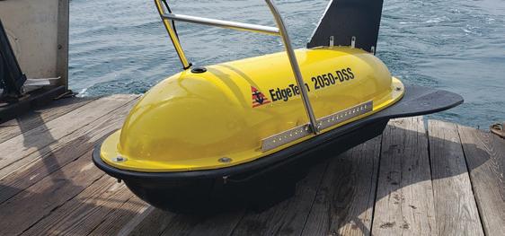
2 05 0-DSS COMBINED SIDE SCAN SONAR & SUB-BOTTOM PROFILER
• Versatile: Tri-Frequency Side Scan to cover a range of applications
• Capable: Towfish based CHIRP Sub-bottom profiler to deliver higher resolution data
• Loaded: Built-in pressure (depth), heave, pitch and roll sensors
• Flexible: Support for 3rd party sensors
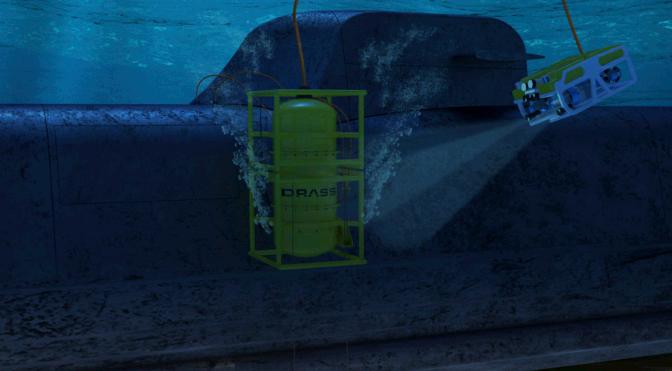
DRASS SAVER RESCUE
Italian diving company Drass has developed SAVER, an effective and reliable submarine rescue system that can be deployed from its specialised vessels.
SAVER essentially merges technology developed for use in the offshore sector, with the practical experience of submarine rescue operations. The result is a system that is light and modular enough to be air transported in a 40-foot ISO containers.
The SRV Submarine Rescue Vehicle is based on a work-class ROV (typically, a SAIPEM Innovator 2.0) tethered to a mother ship to supply the unit with control and electrical power.
The Innovator 2.0 is capable of dynamic positioning and station keeping as well as good manoeuvrability in strong currents while also being able to carry heavy payloads.
It also offers a wide choice of grabbers and manipulators that can enable preparation work for rescue operations. When not connected to the submarine rescue system, the WROV can operate independently.
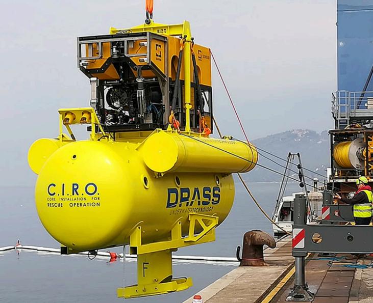
The ROV is connected through a standardised electro-mechanical interface to a Capsule for Intervention and Rescue Operation (CIRO). This pressureresistant capsule can accommodate the submarine operators and crew as well as providing a life support system
capable of sustaining up to 25 people for 87 hours or extending life support duration for a lesser occupancy (eg, 19 people for 96 hours).
This assembly is launched from the moon pool of the rescue ship. The moonpool offers the highest reliability and safety standards even in extreme sea conditions thanks to the rail guides and protection of a passive cursor.
The cursor extends outside the ship keel, protecting the SRV from accidental bumping against the hull It travels down to the submarine powered by the ROV.
At the base of the CIRO is a variable inclination skirt that allows it to mate with the submarine (if pitched and/or rolled). This allows he submarine crew to pass through this watertight port into the CIRO body.
It then flies to the surface vessel where the main wire pulls the SRV gently into the cursor which is conically shaped to connect with the entrance of the SRV frame.
The crew from CIRO can transfer through a hyperbaric connection trunk into a decompression hyperbaric
Capsule for Intervention and Rescue Operation (CIRO
SYSTEM
chamber installed on surface rescue vessel’s deck
CAPSULE
Drass also offers a smaller submarine rescue capsule based on the McCann bell principle. This rescue capsule allows connection to submarines lying at a depth of up to 300 msw.
Controlled by two people, it is lowered on the end of an umbilical able through the water and onto the submarine. It can lock on to a submarine lying at an
angle of up to 10deg. It can recover up to 8 people at a time.
In addition to the rescue bell itself, the entire rescue support system includes an umbilical cable (winch and pulley) deployment system, the umbilical cable itself, a command and control container and the bell’s deck cradle.
VENTILATION SYSTEM
In order to provide the submarine with fresh air from the surface and remove the waste air directly at depth, DRASS have developed a patented Ventilation System ( VS). It creates the required flow to vent the submarine without any pressure build-up inside. This increases the survivability of people in the distressed submarine while waiting for rescue operations.
The VS system is based on a pair of HP compressors installed in a subsea pressure resistant capsule that connect
with inlet and outlet lines/hoses to the submarine by divers/ADSs/ ROVs depending on the available means, the operational conditions and the submarine interfaces.
It works down to an operating depth of 300 msw (extendable up to 600 msw) and is suitable for a crew of up to 60. It provides air with a flow rate of 30 Nipm/ person some systems allow the transfer of materials such as food, lithium hydroxide, medical kits, et cetera from the surface in a dry mode.
DECOM CHAMBER
Drass has designed a One-Man Transportable Decompression Chamber is a single lock hyperbaric chamber for commercial surface diving. It is designed to support shallow water diving operations in locations, such as on-board vessels, where access to a fixed recompression chamber is not immediately available.
The chamber is manufactured in special aluminium grade suitable for the marine environment.
The one-man chamber can be connected to the equalisation chamber or transported to a fixed hyperbaric facility where treatment can be completed, without having to depressurize the diver. It 1010 mm wide and has a height 1170 mm and has a working pressure of up to 7 bar (70msw).Its total weight of 370 kg includes four 14-litre air bottles.
Ventilation System
Rescue Capsule
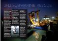
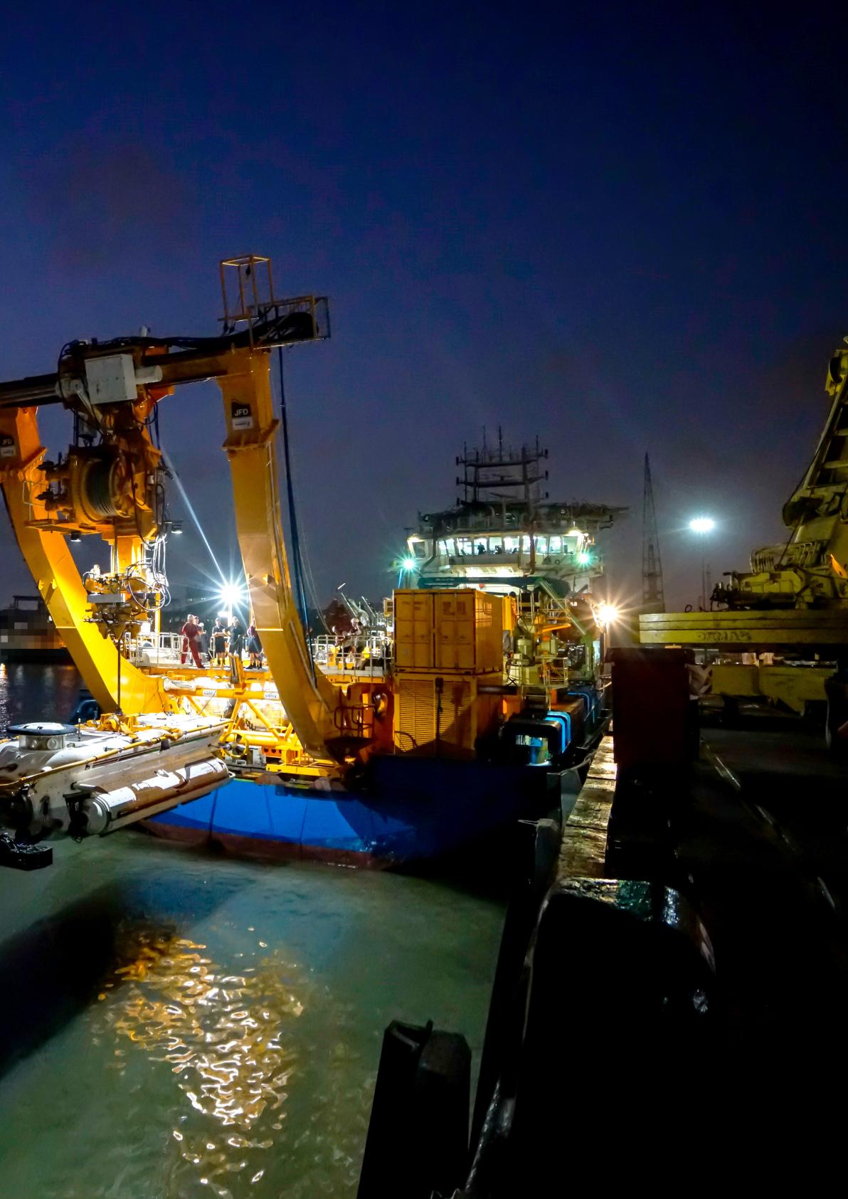
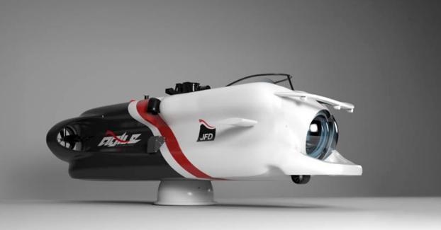
JFD SUBMARINE
JFD’s 40 year involvement in submarine rescue systems effectively dates back to submersibles used in the ‘70s. As the oil industry began to establish itself in the North Sea. Diver lockout submersibles were used to carry out offshore inspection while also allowing divers onboard to carry out intervention work.
Although much of the work was later superseded by ROVs and other underwater vehicles, the lockout vehicles were destined to be fore-runners of today’s rescue submersibles.
FIRST GENERATION
“JFDs first generation Submarine Rescue System was developed around the LR5 submersible – ” said Stuart Irwin.
“The pressure hull for this submersible was originally made entirely from glass reinforced plastic (GRP) but over the years (since 1999), we have replaced this pressure boundary with hightensile steel, reconfigured the hull
design as well as upgrading many of the systems.
“GRP is a very good material from a pressure cycling point of view, but from a longevity point of view, it is difficult to guarantee its lifespan due to not being able to carry out comprehensive nondestructive testing on the material.
“Over the years, we have adopted different types of steel for our submersible pressure hulls. The interface pieces (e.g. flanges between the hull sections or on the transfer skirt or on the viewport seats) are normally fabricated from a different material to the shell, as these areas are generally bare metal and need to be corrosion resistant.
The remainder of the structure is higher strength carbon steel and is protected from the elements by a durable paint finish.
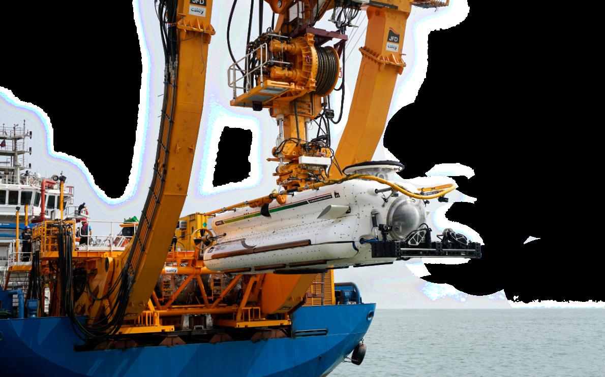
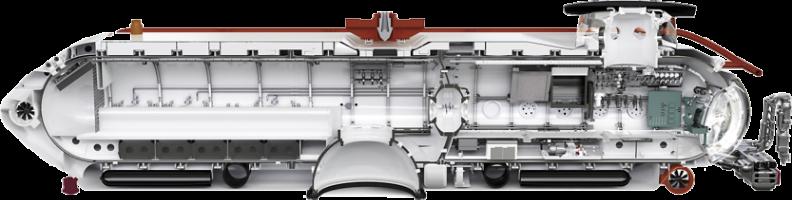
“Even today, all our rescue vehicles are untethered, free swimming and electrically powered. They generally have a two-compartment configuration, the forward section housing the pilot and co-pilot while the aft compartment forming the rescue chamber.
The rescue chamber has a mating skirt and it is this that mates onto the escape hatch of the stricken submarine.”
SECOND GENERATION
Learning from operating these vehicles allowed JFD to design and build its second generation systems.
Lessons from the Kursk incident in 2000, and the drive to develop Transfer Under Pressure (TUP) capability is what largely differentiates 2nd from 1st generation systems.
“Examples of these second generation systems are Korea’s DSAR-5 and Singapore’s DSAR-6.
“Fundamental improvements over the first generation systems included a modular build strategy, which allowed vehicle interiors, exteriors and hulls Vehicle for the Indian Navy
SUBMARINE RESCUE
SUBMARINE RESCUE
to be manufactured simultaneously, reducing cost as well as improving accessibility for through-life maintenance.
“The second generation systems also featured improved battery technology, moving from lead acid to lithium polymer, which provided far greater power and endurance. It also featured more modernised control, navigation and communication systems
“In recent years, there have been submarine losses, in Indonesia (KRI Nanggala) and Argentina (ARA San Juan). Unfortunately, these submarines were lost in waters deeper than
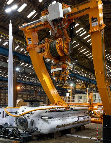
FLYAWAY LARS
While the rescue vehicle is important, the launch and recovery system also deserves consideration. Flyaway systems need to be transportable yet strong enough to operate in sea states (of up to 6).
“The LARS and decompression system was designed as an integrated, yet modular, unit,” said Irwin. “Three chambers sit under the mezzanine deck along with other containers such as mechanical workshop. This results in a significant deck space savings.
Indian rescue system
would have been possible to conduct a rescue. Despite this, there is considered a greater
likelihood of an incident occurring in local, shallower, waters such as the submarine
“The A-frame design also allows the rescue submersible to traverse across the crossbeam to align with any of the three decompression chambers.”
The ability to operate from the widest possible variety of Motherships in the widest possible range of sea states is the key driver for any flyaway rescue system.
Generally, there are two types of submersibles, tethered & untethered, both with their own advantages and disadvantages.
Tethered Submersibles require a MOSHIP with either fully redundant dynamic positioning (DP2) or a fourpoint mooring system.
Free swimming Submersibles do not require an umbilical, umbilical winch or cursor, and use a much simpler A-frame, saving weight, space and mobilisation time.
coming out of port, postmaintenance or passing through shipping channels.”
Flyaway LARS with rescue craft Image: Caley Offshore
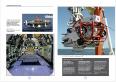
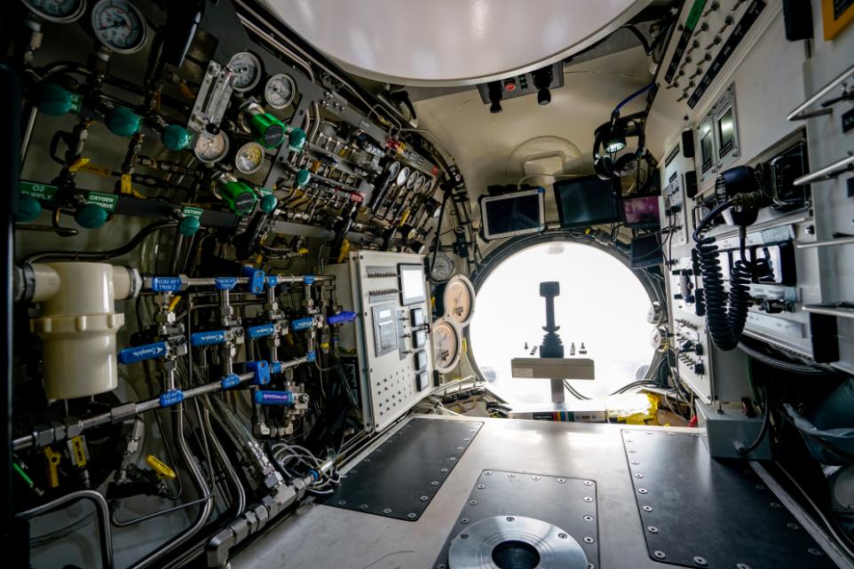
Inside the rescue vehicle
THIRD GENERATION
The main design driver of the most recent generation (Third Generation) submarine rescue systems has been to improve overall capability, especially the Time to First Rescue (TTFR).
JFD’s third generation SRVs have a depth rating of between 500m and 650m and can accommodate 17 rescued submariners (rescuees) in addition to its own three crew. A rescue submersible has 108hrs of life support.
The design also has improved operability, diagnostics and maintainability.
The system has been designed to further reduce the number of ‘planes and lorries required while maximising the number of vessels able to carry the system.
JFD is currently working on its fourth generation system.
RESCUE PROCESS
A typical rescue operation might commence with an ROV being deployed to conduct search and reconnaissance intervention activities such as posting emergency life support stores, pods, providing sonar location, removing debris and clearing obstructions from the rescue seat on the submarine.
“Submarines may have more than one escape hatch but typically, one is located halfway along its back. This access hatch is surrounded by a reinforced
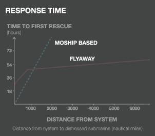
MOSHIP vs Flyaway
There are two schools of thought regarding how a submarine rescue system should be used. Some submarine rescue systems would only be deployed in local waters, so it would be advantageous for them to be based permanently on a dedicated mothership ( MOSHIP).
This MOSHIP would always be immediately ready to sail and able to reach the local submarine very rapidly.
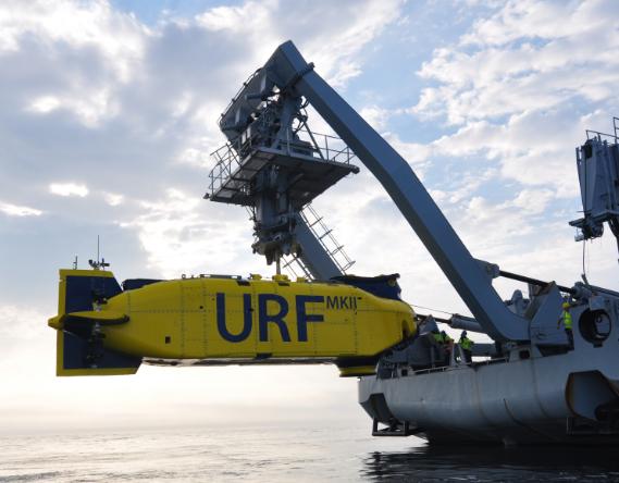
Such systems are reliable and low risk and in between exercises or emergency rescue operations, the mother vessel can be employed in multi role hydrographic survey/ oceanographic research or used to deploy uncrewed systems. She Swedish Navy recently sailed HMS Belos ( used to support the URF Mk II submarine rescue system) to Finland help investigate the damaged Eastlink Power cables.
Other navies with a much greater breadth of operations require a more global response. This has resulted in the design of ‘Flyaway’
systems designed to be loaded onto aeroplanes and flown around the world to be deployed on board a Vessel of Opportunity (VOO).
The system is designed to be modular and easily transportable It is normally located on land but can be air transported anywhere in the world. In important factor in the design is a minimum mobilisation time.
“The rescue system for both applications is fundamentally similar, the difference being in the configuration for portability.,” said Macpherson.
“Local systems, not designed for disassembly, can be less complex, and their weight isn't such a concern. Conversely, in flyaway systems we are much more conscious of the materials getting used to minimise weight, and how the system is packaged, disassembled and then configured for transport.
“A typical rescue submersible is about 10m long, 3m wide and weighs between 25 and 30 tonnes. This is quite a heavy piece of machinery to move and while it is generally well within the capabilities of the military, an important consideration in the operation is knowing how many aircraft are needed to move all the support equipment and the number of trucks each end necessary to transport the equipment from the base to the airfield and ultimately the port of embarkation.
Moship vs Flyaway
Similarly, the containers must not be too heavy for the available lifting equipment that gets them on and off the aircraft, and the operators must ensure the same equipment is available at the other end.
The operations, therefore, require detailed end-to-end planning, especially when communicating between government, civil and military organisations.
The entire underwater vehicle sector seems to be changing towards autonomous vehicles. Will submarine rescue follow this route?
“It is possible, with current technology, to pilot a manned underwater vehicle remotely, but I believe the need for human interaction remains,“ said Irwin.
Piloting a submersible is a physically and mentally taxing activity, the use of automation is an area where this workload can be reduced.
We are already including greater automation such as having a touchscreen control interfaces in the pilot consoles to engage electronic actuation of equipment rather than physically operating valves and switches.
‘There are two configurations for transferring under pressure. One is the vertical transfer method which transfer the survivors down through the skirt into the decompression complex on the vessel.
There is, however an alternative Horizontal transfer which generally used for a flyaway system, where rescuees transfer from the SRV into the TUP system through the back hatch.”
structure to withstand the intense hydrostatic pressures acting on it,” said Macpherson
“The interface is known as the ‘rescue seat’ and the design is strongly governed by NATO standards for interoperability, stipulating the physical requirements, known dimensions, flatness and strength tolerance.
“When the rescue submersible’s mating skirt lands over this seat, the pressures are equalised, creating a secure and watertight connection. It is a crucial interface with most submarine rescue vehicles in operation currently globally, using a similar transfer skirt design.
The mating skirt has a substantial large profile rubber seal which allows for a moderate deviation in the surface roughness and flatness of the rescue seat while being able to accommodate minor debris. During mating, water in the skirt is pumped overboard to lower the pressure and achieve a 'soft seal'. Once the skirt internal pressure is equalised with the rescue chamber, this is called a 'hard seal'
“Because water is incompressible, it is possible to easily equalise the pressure inside the cavity within the skirt to one atmosphere. Outside, however, there are maybe 50 atmospheres so at 500 m there is effectively 800t holding the rescue submersible firmly onto the rescue seat. The rescue seat and supporting structure must be designed to withstand these forces.
Swedish rescue sysem
Vehicle cutaway
SUBMARINE RESCUE
FOURTH GENERATION RESCUE SYSTEM:
So what features could we expect to see in a prospective fourth generation rescue system? In fact, JFD is at an advanced stage of designing such a vehicle.
Called Agile, the operating principle remains the same, but it incorporates the latest technology to make performance improvements and increase mission effectiveness.
“The key aim is not only to reduce the amount of time it takes to get there, but also to reduce the time to carry out the rescue mission,” said Irwin. “One way to achieve this is to increase the rescue capacity.
“In order to retain the same footprint, the overall length is similar to existing designs but internally, we have reduced the length of the command module. This creates more space in the rescue chamber, allowing a larger number of people to be rescued during each sortie.
“JFD is also heavily focused on the commercial diving market and we're incorporating a lot of the state of the art equipment employed there, especially embracing automation.
“The Agile SRV will be a steel hulled craft incorporating a traditional transfer skirt but it will adopt the latest technology in terms of control
AGILE
systems, electrical distribution, battery management, lighting, cameras and how data is transmitted back to the surface, ” said Macpherson
“We have highlighted areas where we can make real improvements over previous designs, which should allow the system to be easier and more cost-effective to maintain.”
Agile fourth-generation vehicle
Agile bring loaded for air transport
SUBSEA CABLE REPAIR
INDUSTRY ANALYSTS SPINERGIE EXAMINES OFFSHORE CABLE REPAIRS AND HOW THESE OPERATIONS IMPACT THE MARKET
By year-end 2023, cable laying vessels (CLVs) had installed 2345km of cable across various industries ensuring a record year.
The length of cable laid, the first time the 2000km marker had been reached, was over 650km more than in 2022 and almost double the volume recorded in 2017.
According to market analysts Spinergie, the strongest growth in the cable market has been in wind farm export cables, with a 33% increase in 2023 compared to 2022.
Further growth in the subsea cable industry is anticipated, and contractors have reacted accordingly. At least 11 newbuild cable layers are on order, with three of those units already having work lined up, the first from mid-2026.
This is in addition to the four newbuilds that have been delivered to the market since the beginning of 2022.
While the market is booming, however, it is crucial to consider additional strains on fleet time, including cable failure. How do, subsea cables fail. Array cables and telecom cables were not included in the study.
CAUSES OF CABLE FAULTS
There are a variety of factors that can cause cable faults, ranging from issues that arise during the manufacturing phase to those that show up later through accidents or mishaps.
INSTALLATION AND EXPOSURE
There are two types of issues that can arise during installation that are most likely to cause failure at a later date.
Mishandling during the installation process is the first potential issue, and this can arise via damage sustained from tools and equipment, a kinked cable,
Kilometres
or bird caging.
This is a type of distortion that sees the individual outer strands of a cable unravel and expand to ultimately create a bird cage shape at the damaged area.
Exposure is also a key factor and can arise if the cable is unprotected due to currents or if there has been insufficient seabed preparation or reduced visibility during cable laying operations.
Exposure then leaves the cable vulnerable to abrasion and external damage.
FISHING AND ANCHORS
Fishing activities pose a significant risk to subsea cables. Fishing gear, like trawlers or nets, can snag and damage the cables, leading to mechanical failures.
Ship anchors are another common external cause of failure, as their being dragged across the seabed has the potential to displace or sever cables.
REPAIR MARKET
Finding the fault:
An indicative timeline
THE MARKET IMPACT
The short-notice mobilisation of CLVs and construction vessels (CSVs) for just a few weeks at a time to deal with subsea cable failures can be significantly disruptive, hindering both the efficiency and cost-effectiveness of power infrastructure.
Spinergie analysis has observed that, since 2016, there have been 149 subsea cable repair activities across 97 different cables. This includes wind farm export cables, oil and gas cables, and interconnectors.
Analysis indicates that power cables had the most repairs overall, but this category also saw the least amount of repairs compared to lifetime and length. This suggests that the depth and remoteness of interconnector-type cables can lower the chance of external damage, one of the most common causes of failure.
MANUFACTURING AND MISUSE
Faults can be caused even before installation. Cables with manufacturing defects can experience corrosion more easily and may also be subject to thermal issues surrounding cable insulation. Finally, when the cable is in use, inadequate power or defective insulation can lead to overheating, which, in turn, compromises cable integrity because the cycle of overheating followed by cooling results in damage.
HOW CABLE FAULTS ARE FOUND
1 Failure Location: At the earliest stage, measurements are taken from the substation in order to estimate the location of the failure. Once this general point is located, a construction or survey vessel with an ROV is deployed to find the exact point of failure.
In some instances, this process can take months, as was the case with the Basslink subsea
In wind farm export cables, the average rate of failure is 0.0024 failures/year/km, which means a wind farm with 100km of export cable has a 24% chance of cable failure in any given year. The cumulated probability of failure would reach 95% in 11 years.
While a cable could go years without a failure, some cables suffered more than others, a key example is the Malta-Sicily Interconnector, which was damaged twice in two years.
cable failure in late 2015. Ultimately, the fault was discovered and was likely caused by the heating and cooling of the cable under operational stress, but this process lasted into late 2017.
2 Preparation: Next, the faulty cable section is cut, tested, and removed. The cable ends are then sealed to prevent water ingress and hooked up to buoys.
3 Mobilisation: An available CLV is then sent to the operations base. Replacement cables and joints are loaded from storage.
4 Repair: In the final stage, cable ends are recovered. The first-in-line joint connects one cable end to the replacement, and jointing is performed at the other end. Finally, the repaired cable is laid back on the seabed
CASE STUDY: MALTA-SICILY INTERCONNECTOR
The Malta-Sicily interconnector, operated by Enemalta, was commissioned in March 2015. Manufactured by Nexans, it is 94.7 km in length (220kV HVAC) and is laid in water depths between 14 and 160 meters.
CAUSE OF THE FAILURE
The interconnector, a power link between Malta and Sicily's power grid, was damagved in December 2019. Two of the three conductors and all fibreoptic lines were damaged. The primary cause of the damage was identified as a ship's anchor, cutting the cable in two at a depth of 150 meters, with Singaporean-flagged oil tanker Di Matteo the culprit. The cable was situated on a sandy seabed, where it could not be trenched but was instead laid using a jetting process.
RESPONSE AND REPAIR PROCESS
In early January 2020, Nexans mobilized the construction vessel Argo (then Polar King) to inspect the cable damage. An ROV located the exact damaged spot. The damaged part of the cable was exposed by Argo using a water-jetting system.
In mid-February, Asso.subsea's cable repair vessel Ariadne was mobilised from Athens to Malta to begin loading the spare cable. CLV Atalanti also participated in the repair process. The damaged section was cut out, and the ends were sealed in preparation for the repair. In mid-March, a spare cable was spliced in at the damaged area. After the splicing, the interconnector was re-energized, restoring the connection.
The Argo returned in late April to trench the repaired cable section to a depth of approximately 1.5m.
ECONOMIC IMPACT
The repair contract was valued at €11 million, with repair vessels mobilized for a combined 54 days. Enemalta's contingency plan during repairs involved powering all available power plants at a cost of around €150,000 a day.
In March 2022, the anchor of another tanker, Chem P, damaged the same cable again during a storm. This time, Nexans Aurora was sent on the repair mission in November, with operations taking 20 vessel days.
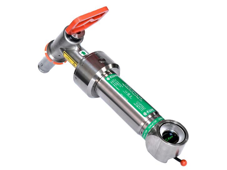
WITH TDR INNOVATIVE
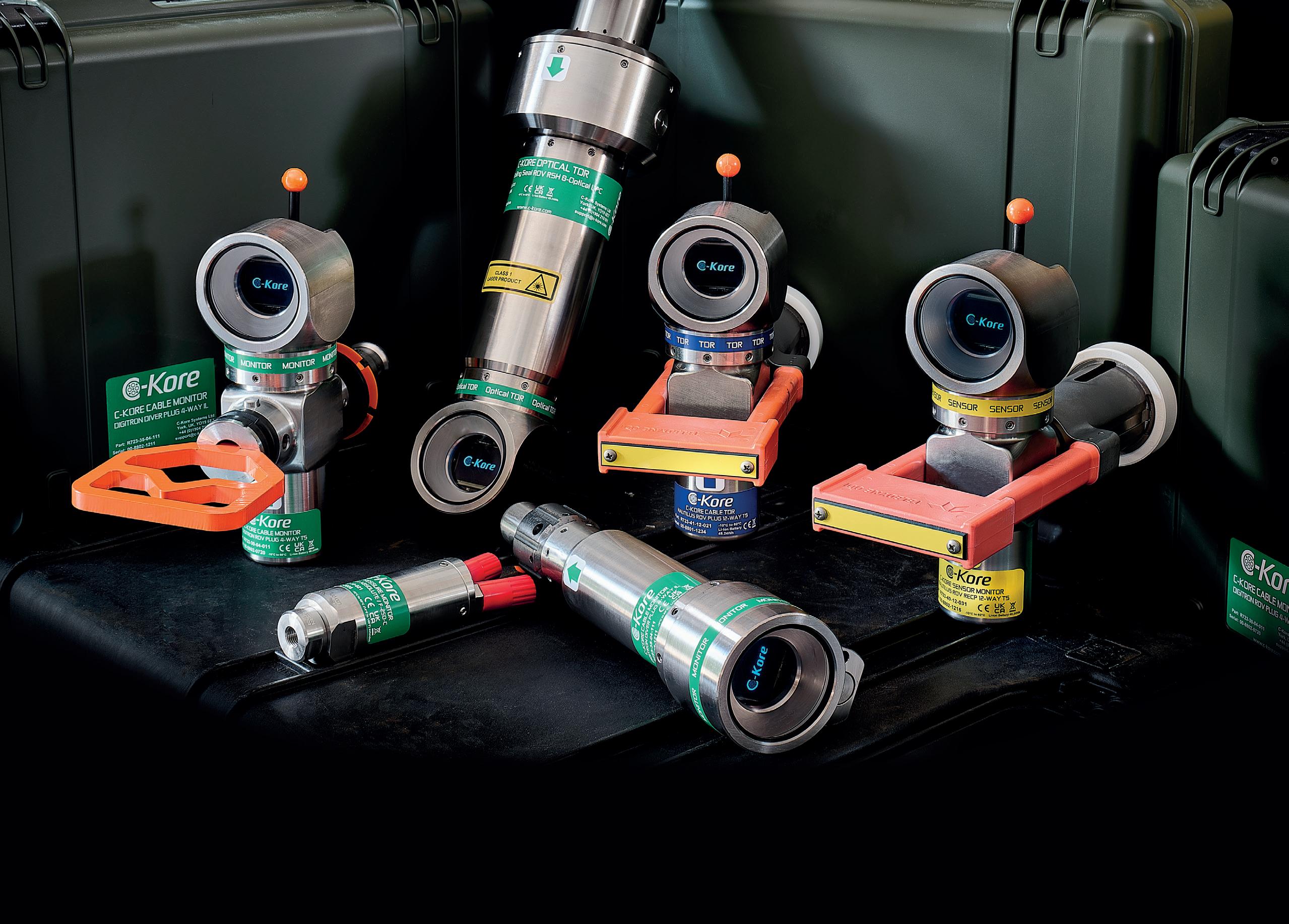
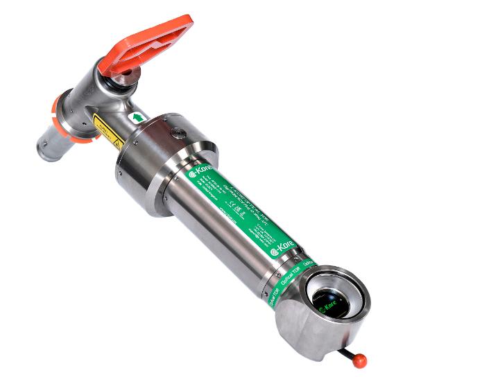
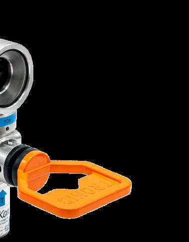
C-Kore Subsea OTDR Tool
Subsea cables play an indispensable role in ensuring the seamless transmission of power and data across vast underwater distances.
While C-Kore Systems, a UK based company, currently focus on testing umbilicals and cables within the oil and gas sector, the same principles of fault-finding and maintenance can be applied to subsea power and communications cables.
C-Kore’s innovative Subsea TDR (Time Domain Reflectometry) and OTDR (Optical Time Domain Reflectometry) technologies are designed to identify and precisely locate faults in underwater systems.
These tools are transforming the way subsea networks are managed, ensuring reliability and efficiency in the oil and gas industry and paving the way for potential applications in global communication infrastructure.
TIME DOMAIN REFLECTOMETRY
TDR is a technique widely used in locating faults in onshore electrical systems. C-Kore Systems has adapted this technology for subsea applications. The ability to distribute electrical power on the seabed of oil and gas fields is mission-critical, as it ensures the operation of subsea control modules on xmas trees and manifolds.
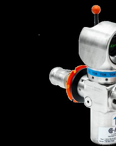
AND OTDR INNOVATIVE FAULT-FINDING
However, the integrity of these electrical systems can be compromised over time, putting oil and gas production at risk. Working much like a radar, C-Kore’s Subsea TDR tool transmits an electrical pulse into a cable and records the pattern of electrical reflections returned.
These reflections are caused by local differences in impedance, which may result from connectors, splices, nodes, or faults such as breaks, shorts, and water ingress. By calibrating the time-of-flight of the pulse to and from expected reflections, engineers can determine the distance to any anomalies observed.
Historically, TDR was challenging in subsea environments due to the attenuation of signals over long distances, impedance mismatches of the testing equipment and the complex echoes from subsea splices and connectors.
C-Kore addressed these issues by moving the TDR tool closer to the subsea infrastructure and automating the entire testing process. This enables operators to pinpoint faults with great accuracy, significantly reducing repair costs and operational downtime.
OPTICAL TIME DOMAIN REFLECTOMETRY (OTDR)
The OTDR works similarly to TDR, but instead of electrical pulses, it sends out a signal of light and detects
the reflections that come back. Anomalies along the fibre, such as splices, bends, and connectors, send back reflections. By knowing the transmission properties of the fibre and the time it takes for a reflection to return, the distance to each anomaly is accurately calculated.
C-Kore's Subsea OTDR simplifies the task of performing OTDR measurements on subsea equipment. As with the rest of CKore testing tools, The OTDR unit is battery-powered, automated, and programmed to run a test sequence for up to 12 fibres.
The tools are so simple to use, the need for specialised personnel offshore is eliminated. The data logged in the unit’s internal memory can be analysed to pinpoint the location of faults with high precision.
BROADER APPLICATIONS: SUBSEA POWER AND COMMUNICATION CABLES
As global communication networks expand, the need for reliable subsea communication cables grows. Whether it’s for internet connectivity, scientific research, or military applications,
these cables must be fault-free to ensure seamless data transmission.
The application of TDR and OTDR technology can provide quick and accurate fault-finding capabilities in these applications, minimizing downtime and maintaining connectivity. While the world increasingly turns to renewable energy sources, subsea power cables are also becoming more prevalent.
Wind farms, tidal energy systems, and other offshore renewable installations all rely on robust subsea power cables. Here, the same TDR and OTDR technology can be employed to ensure the reliability of these critical connections.
The use of Time Domain Reflectometry (TDR) and Optical Time Domain Reflectometry (OTDR) represents a significant advancement in subsea faultfinding technology. These methods offer precise and efficient solutions for detecting issues in both electrical and optical cables, crucial for maintaining the integrity of subsea operations across various industries.
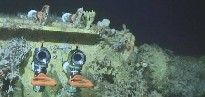
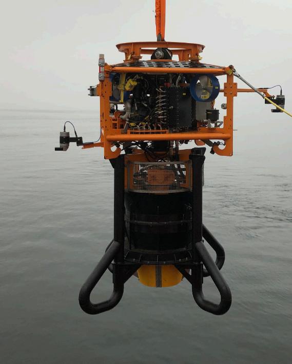
C-Kore Tools deployed on an Umbilical UTA
CABLE RECOVERY
USING A UTROV TO RETRIEVE SUBSEA CABLES
A subsea cable repair typically commences with the damaged line lying on the seabed and needing to be cut and retrieved to the surface. What is the best way of doing this?
One common way is to drag a grapnel across the line in an attempt to snag it. Some grapnels incorporate a cutting blade which can intentionally sever the line. Other grapnels are designed to hold on to the already cut line and bring it to the surface.
There are, however, other means of performing cable cut and retrieval operations. One such is to utilise the highly adaptable UTROV System.
The UTROV (Utility Remotely Operated Vehicle), developed by Scottish firm Utility ROV Services, is a remotely operated subsea tool carrier that is designed to transfer the lift capacity of a deployment winch or vessel crane to the UTROV and fitted tooling.
At its centre lies a through-frame load member certified to a safe working load (SWL) of 55t. This not only allows the platform to deploy and operate a suite of subsea tools, but also for the user to carry out lifting operations and as such deploying or recovering relatively large subsea items.
The UTROV and tool can be manoeuvred laterally by means of its axial thrusters. These control the orientation of the vehicle and assist with positioning during operations.
Inside the frame, dual hydraulic power units (HPUs) create considerable hydraulic power at source, allowing the UTROV system to operate numerous flow-intensive tools.
The keynote of the UTROV system is the number of tools that can be deployed from it and thus, the range of operations it can carry out. Equipment includes Shear Cutters, Tine Grabs, Pipe Grabs, Clamshell Grabs, Controlled Flow Excavators, Rock Bag Deployment Tools, a Mattress Installation Frame and the industry-first 'Mattress Recovery Tool' which has now tallied up the successful recovery of over 4,000 concrete mattresses in the North Sea.
For both pipe and cable recovery, the line is typically trenched to around 1 - 1.5m, so the first stage is often to uncover the sediment on the seabed. This is either conducted using mass flow excavation tools powered by deck HPUs, or in the case of the UTROV, their Controlled Flow Excavator (CFE) is powered by the hydraulic pumps on their vehicle, at source.
“In a recent application, we were called upon to bring a cable to the surface,” said Ruairi Thain, Project Engineer at Utility ROV Services. “Many vessels incorporate their own traditional Work Class ROVs to help with underwater observation and intervention, but in this case, the vessel did not have a WROV mobilised, and with a short timescale to complete the repair, the UTROV system was mobilised to conduct numerous subsea operations.
UTROV with Controlled Flow Excavator
“We were contracted to perform excavation over an area with the cable heavily buried around 2 metres below the seabed. We had to perform adequate excavations to clear away sediment from the cable, before engaging our shear cutter and severing the cable.
“We have numerous hydraulic shear cutters that we can call upon for different products and can thus closely tailor the shear size to specific cutting requirements.
“In this case we retrieved the cable to the surface by using one of our shears not to cut, but to physically grip the cable and pull it up using the crane. The end was placed over a chute on the vessel whereupon the deck crew intervened and attached holdback rigging. The line was then pulled onto a tensioner and then on board the vessel.
“On another project, a previously-made infield export cable joint had failed and required recovery to permit investigative root cause analysis. It was important that the retrieved joint housing section was still intact when recovered to the surface and that no secondary damage was imparted on the joint during the recovery process.
“For this operation, we employed our Multi-Purpose Frame (MPF) with Twin Pipe Grabs. We used these grabs to encompass the 18-metre-long joint section (inclusive of bend restrictors and its 850mm diameter joint housing), before gradually recovering the assembly through the water column and laying it down in a dedicated storage area on deck.
"In certain instances, we are called upon to work in parallel with the WROV onboard. Instead of the UTROV being responsible for lifting the cable
UTROV recovering cable to deck with Multi-Purpose Frame and Grabs
onboard the vessel, we can utilise our grabs to raise the cable from the seabed such that the WROV can gain access to install recovery rigging on the cable end.
“Once installed, the client can then recover the cable using their preferred methodology.
UTROV with 1400T Shear Cutter
CABLE REPAIR
When a cable fails, be it a communications or power cable, the loss in revenue can be significant. Perhaps of the most challenging aspects of any subsequent repair is not the complexity of the cable, but availability of a suitable vessel and spread to carry out the task.
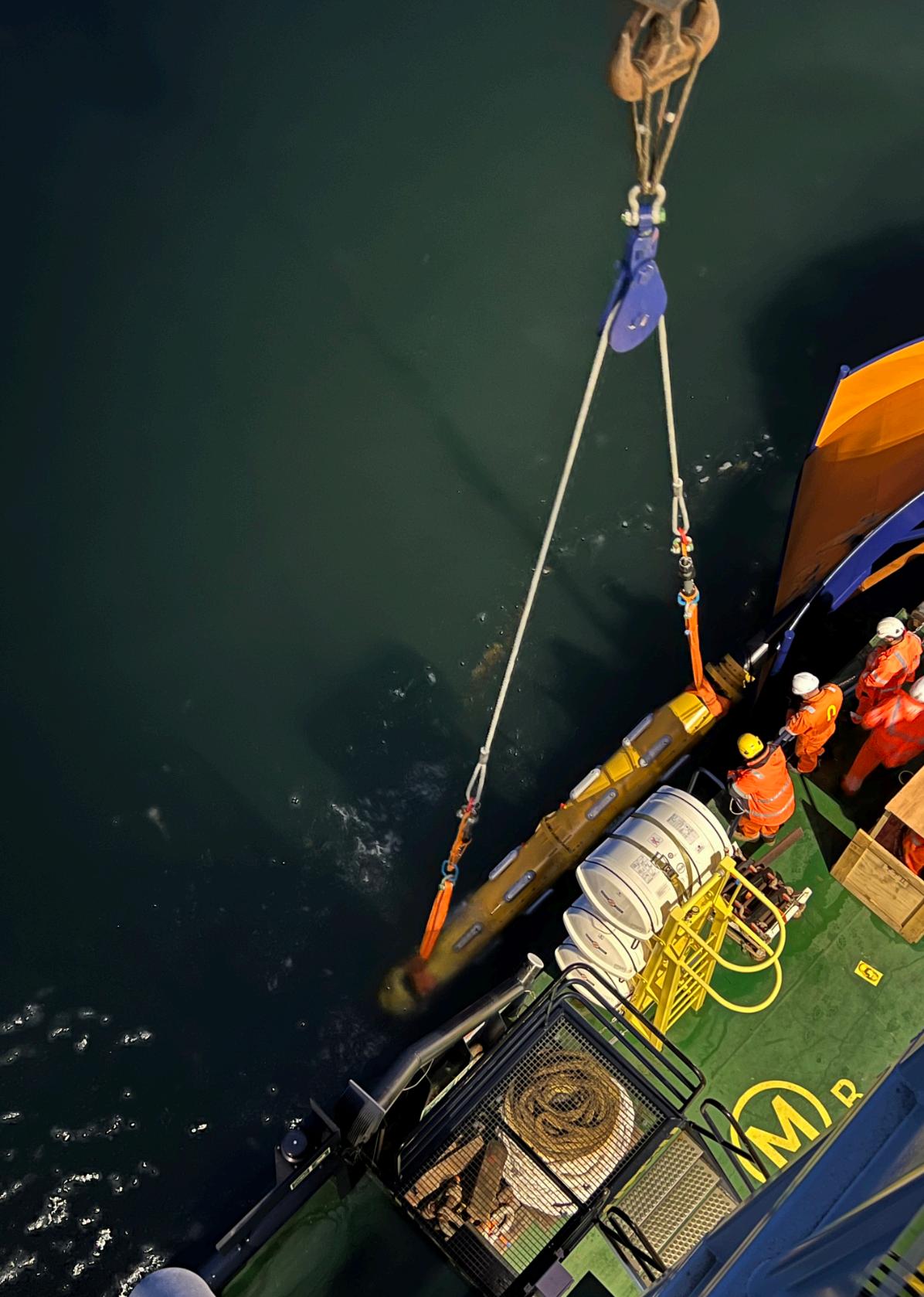
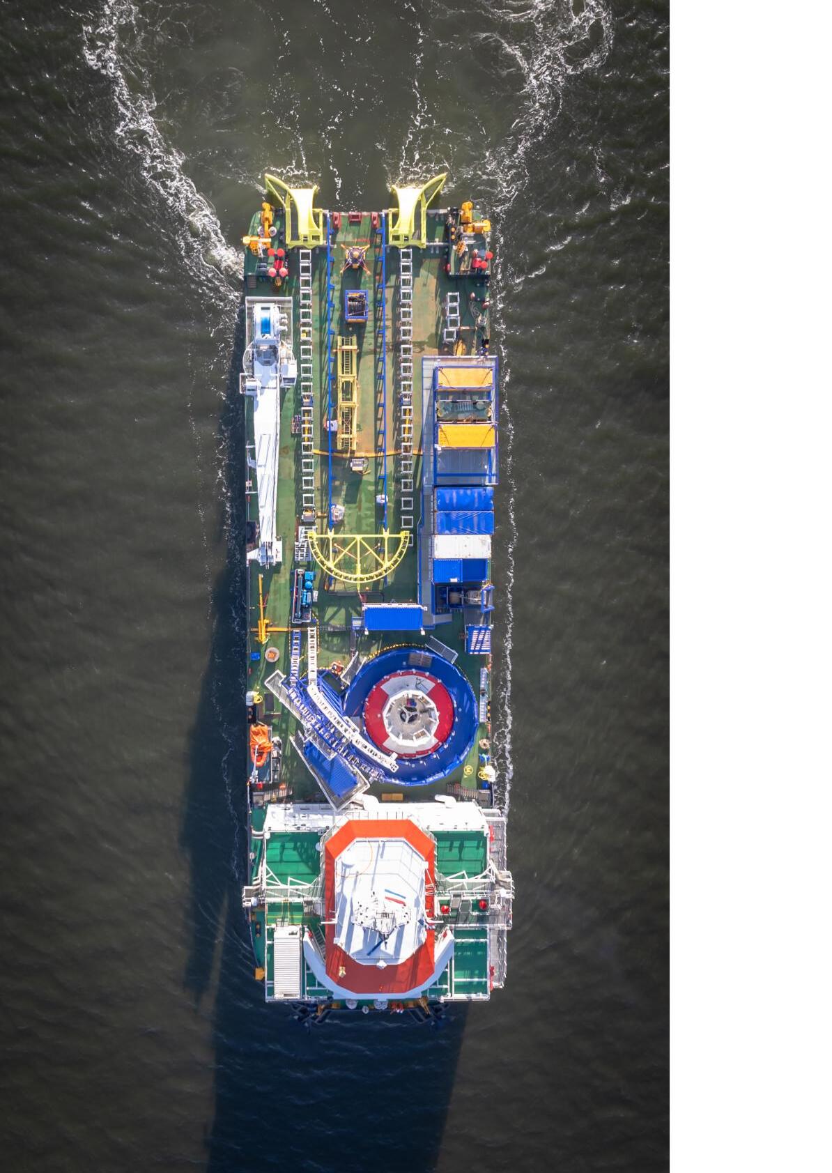
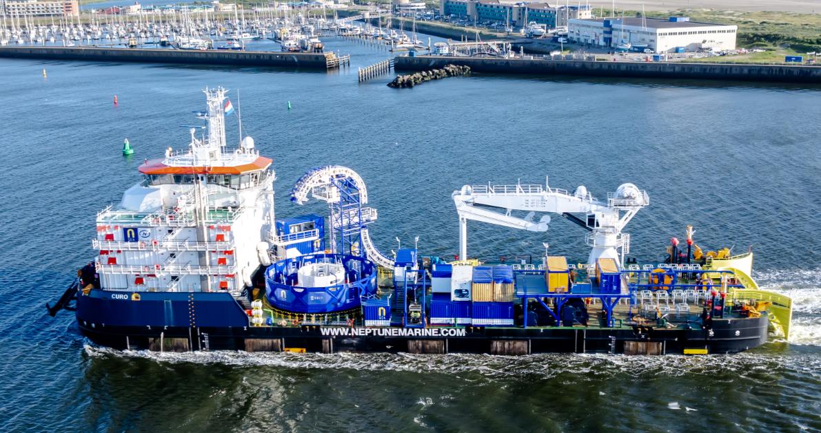
N-Sea has made a commercial decision to keep a monohull, the Curo, on standby, to react immediately to cable repair issues. Dale McDonald, Operations Manager- Subsea Cables at N-Sea speaks to John Howes about aspects of cable repair and how this vessel spearheads its response.
Cable faults are not uncommon but the costs rising from transmission failure can be disproportionate. It may be that the output from an entire windfarm can be interrupted until the cable repair is made.
“Repair operations largely depend on where the problem lies,” said Dale McDonald. “It might be within the inter-array cables linking the wind turbine generators (WTG) back to the substation. These are often only a kilometre or two in length and it is often proves more economic to conduct a full replacement instead of replacing a small section with subsea joints.”
The lines transporting the energy from the offshore platform back to the shore, however are tens of kilometres in length and it can get interesting when the fault is somewhere along this export cable.
“The basic repair principle is to find the fault, de-bury a length of line to expose the cable, cut thye line underwater and bring each end to the surface/vessel to make the repair,” said McDonald. “The two ends are then connected to a new length of cable stored onboard the repair vessel by subsea joints.
“If the cable failure is only say, one kilometre away from the offshore substation, the operator may choose not make the second joint connection but instead pull the second end straight on to the platform.
“It is possible to tell roughly where the fault lies by employing different fault finding techniques from the shore or platform. The accuracy of the fault-finding can depend on the the distance from the testing location.
“Another challenge may be to find the buried cablein the first place. Sending an underwater vehicle to look at the area may provide clues, but the search can be helped by many submarine cables being pre-magnetised.”
This magnetisation can occurs during the cable manufacturing process or for larger submarine power cables, the process can be carried out either onshore during the cable loading or even offshore during the cable lay.
“The next task is to expose the cable,” said McDonald. “The tool often chosen for this is a controlled flow excavator (CFE).
“The length of cable excavation is dependent on the water depth. The exposed length of the trench must be at least equal to the length of the catenary because if a section is still stuck into a buried trench it compromises the cable integrity.
“The exposed cable is then cut subsea and recovered using a grab or rigging which applied by the ROV.
“Depending on the water depth, in a straightforward cable repair it would be common to replace 300500 m of cable as a minimum
although if this cable crosses another asset this also increases the cable repair length to take into account the crossing boundaries
“Once one end is recovered to the surface, the cable is sealed off to stop any water ingress. The cable is then closely examined to pinpoint the specific fault location and ensure it has been cut out.
“We then introduce a new length of cable stored either from carousel or a wheel drive (vertical wheel drum) and carry out an inline high voltage joint between the recovered cable and the Omega cable. This is very timeconsuming - the operation can take in the order of 5–7 days to make the joint.
“A typical three phase AC cable is composed of three conductors with a fibre optic cable running through the centre. Conversely, some conductors transmit DC electricity. These cables consist of two separate, smaller-diameter power cores, an out and return line and a separate FO.
“These DC lines are possibly more challenging because while an AC acts as a, intertwined single unit, in practice, the 2cores and the FO line of a DC are individual lines.
“When handling DC, one core misalignment of the cores can make handling more complex. The jointing process is similar for both.
“The metal conductors are physically joined to those of the newly introduced Omega cable by using ferrules to make the connection, although Aluminium cable is often welded. In either case, the precision that's required, especially when stripping back some of the insulation and the margins, is very tight.
“While these processes are not particularly manually intensive, they can be quite time consuming.
“A typical Cable may also contain a pair of 48-strand optical lines for communication control and data acquisition.
“Repairing these connections are also challenging because it is vital that the conductive capacity of the glass is not altered, as this might change the way the signal is carried.
“The joining, therefore, is carried out by intricate splicing machines which fuse the glass lines together.”
“Once all the joins are made, it is encased in a protective canister and resin is then poured in to ensure water tightness. The sealed joint is then encapsulated in a large
Lowering the joint down after a cable repair
CABLE REPAIR
OPERATIONS
One fact not widely appreciated is that a cable repair vessel would probably have a minimum 60 persons involved in this operation.
“There is the marine crew for the vessel, the deck crew for the cable handling,” said McDonald. “We have our ROV on board for intervention and monitoring and the controlled flow excavation team In addition.
There are a minimum 12 high voltage engineers that are doing jointing, typically six guys or girls on either shift. So already you've got at least 12 guys or girls just doing the jointing process
And this is describing a conventional joint in the middle of an export cable. Sometimes if 60 isn't enough you would have to, once you've completed one part of the work you would have to take some people off and replace them with a different skill set so that the next part of the repair can continue.
armoured cylinder around 5m in length which offers additional physical protection. Either side of this joint is a bend stiffener or a bend restrictor.
“Managing the geometry when overboarding this rigid cylinder over the stern chute of a vessel in a dynamic environment is challenging,” McDonald. “The line is deployed back, controlled through back-tensioning the catenary until it reaches the sea bed. We then start to lay out the new cable section while we navigate to the other end of the cable.
“The second cable end is then recovered onto the vessel to be joined with the other end of the new cable. Handling the second joint is one of the most difficult parts of the operation.
“With a single line, it is possible to manoeuvre the vessel into the weather. With two lines, however, movement means collapsing one catenary or the other and this affects the properties of the cable. The final connection takes another 5-7 days at the end of which, we effectively have two subsea cables rising up as catenaries and looped over the repair vessel.
“The completed cable can be returned to the seabed in a number of methods but, most commonly being hung below a large spreader bar
and either ‘flopped’ it forwards or backwards and down onto the seabed.
“The additional Omega line means that there is always going to be an unavoidably large amount of slack in the cable. This is re-buried using CFE.
MONOHULL ALTERNATIVE
Repair vessels are typically monohulls which have relatively large deck space and can move to site quickly. They are not, however, the only type of repair vessel.
“Last year, in the Irish Sea, N-Sea carried out an export cable repair repair from a jack up vessel,” said McDonald. ”We were very close to shore and a conventional vessel would’ve had problems physically getting on site with grounding at the jointing locations being a real concern.
“We decided to use a jack up in the intertidal area, but because of market availability we couldn’t charter one large enough. In the end, we solved this by employing two jack-ups parked next to each other bridged by a walkway. This provided a very stable platform for the jointing process but was limiting in other phases of the repair. “
The Curo
EMEC WAVE TESTING
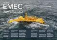
Established in 2003, the European Marine Energy Centre (EMEC) is the world’s first and leading facility for demonstrating and testing wave and tidal energy converters.
Helping to reduce the time, cost and risk of testing innovative, sustainable, technologies, it offers purpose-
built, open-sea testing facilities situated close to excellent harbour facilities.
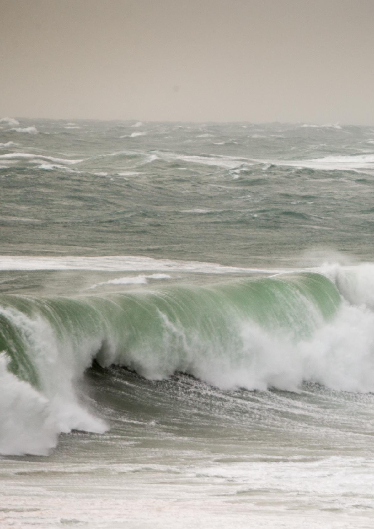
EMEC operates two gridconnected test sites and two scale test sites. The grid connected sites are the tidal test site at the Fall of Warness situated to the west of the island of Eday and the Billia Croo wave test site, located offshore to the west of Orkney’s
Mainland. With strong tidal flows of up to 4m/sec at the Fall of Warness, and waves averaging a height of 2-3m at Billia Croo, these sites are where larger marine energy prototypes, capable of delivering utility scale levels of power are put through their paces. The two scale test sites are where smaller scale devices and prototypes at an earlier stage in their development
can gain real sea experience in less challenging environmental conditions.
In addition to its open sea test sites, EMEC has also helped develop international guidelines for wave and tidal testing and undertaken a wide range of consultancy and research work to support the marine energy industry. It offers accredited
inspection services that enable technologies to have access to independent, internationally recognised performance assessment and inspection.
It became an ISO/IEC 17025 accredited test laboratory in 2005, and an ISO/IEC 17020 accredited inspection body in 2014, the only centre of its kind in the world to have done so.
EMEC)
In its 20+ years of operation, EMEC has hosted 22 wave and tidal energy clients (with 35 marine energy devices) spanning 11 countries at their test sites. Beyond testing and demonstration, EMEC’s expertise has supported projects with environmental services such as consenting and monitoring strategies and the centre has helped other countries in
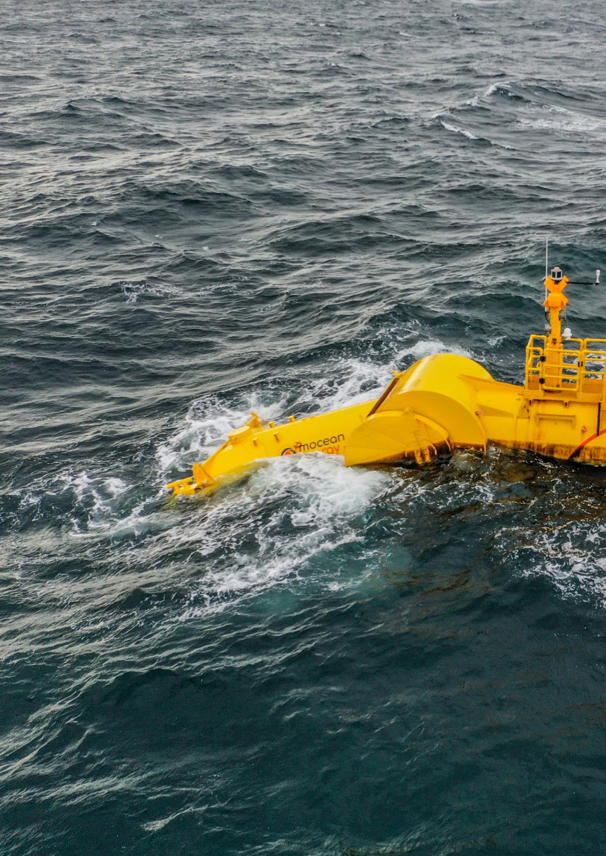
Mocean Energy’s Blue X wave energy converter Image:
WAVE POWER
WORLDWIDE TESTING SITES
BiMEP Area (Biscay Marine)
Mutriku Area (Biscay Marine)
PLOCAN (PLOCAN)
Spain
CEMIE-Océano (CICESE)
Mexico
Hanstholm (DanWEC)
Denmark
Dutch Marine Energy Centre
Netherlands
SEM-REV (Ecole C de Nantes)
Seeneoh (SEENEOH)
Paimpol-Bréhat (EDF)
France
Open Sea Lab (MERIC)
Chile
Viana do Castelo (ENONDAS)
Aguçadoura Test Site (WaavEC)
Portugal
Billia Croo test site (EMEC)
Fall of Warness (EMEC)
Scapa Flow (EMEC)
Shapinsay Sound (EMEC)
META Ph 1+2 (Pembroke Forum)
Perpetuus (PTEC)
Falmouth Bay (U. EXETER)
Fundy Ocean Research (FORCE)
Canada
Jang-Juk Strait (K-TEC)
Uldolmok (KIOST)
KRISO-WETS (KRISO)
Republic of Korea
SMARTBAY (Marine Institute)
Berth A (SEAI) Ireland
Kaba-shima (Nagasaki-AMEC)
Eno-shima (Nagasaki-AMEC )
Japan
Green Island (TaiMEC)
Taiwan
Zhoushan (National Ocean Tech)
CMEC (QUINGDAO)
China
Flatirons CampusLea (NREL)
PacWave North (Oregon Univ)
Tanana River (Univ Alaska) USA
Blue Accelerator (POM
W.Flanders) Belgium
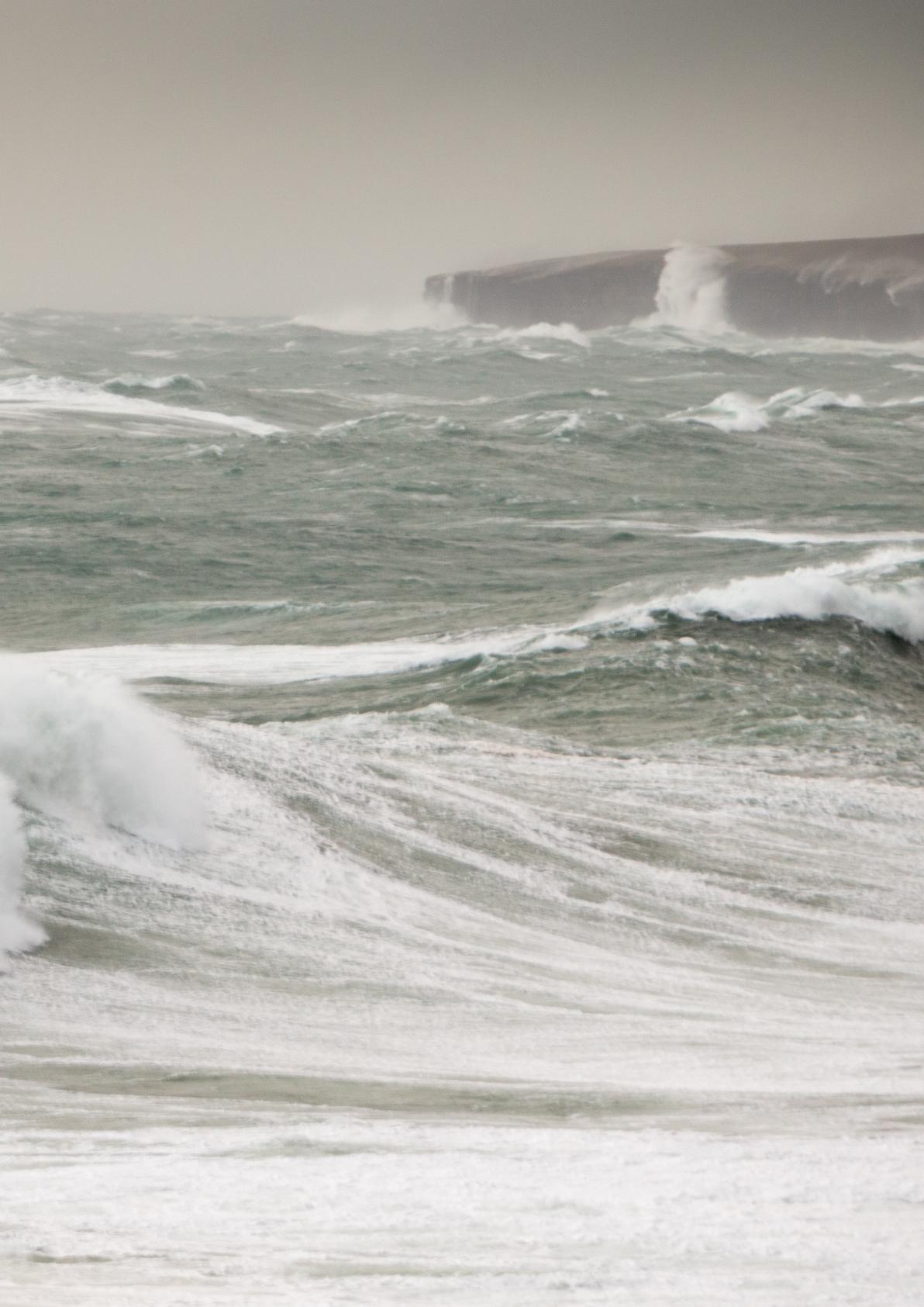
Billia Croo waves (Image: Rob Ionides
developing similar marine test sites across the globe. A selection of the wave energy devices that have tested in Orkney’s waters over the years are introduced below.
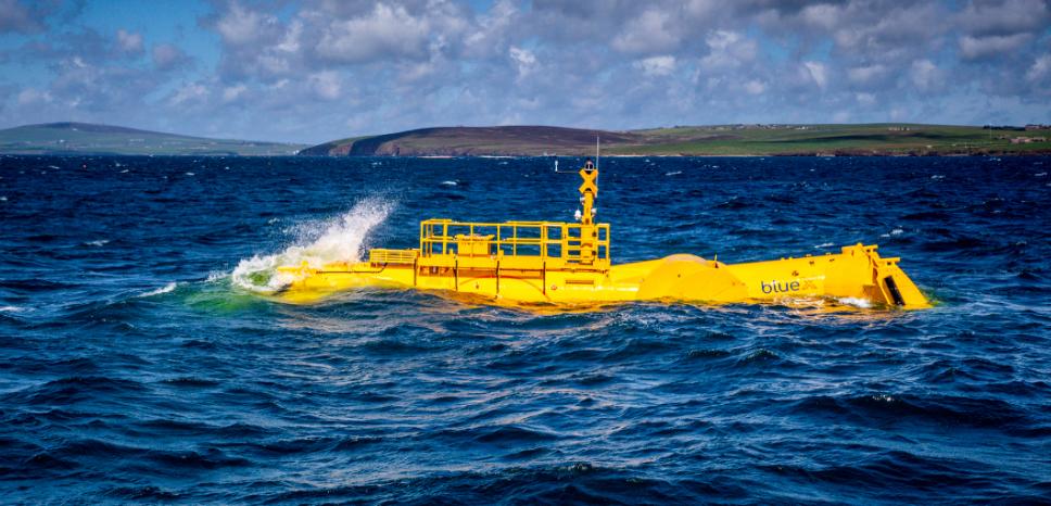
MOCEAN ENERGY are developing two wave energy technologies – the Blue Star, a commercially ready low-power device that supports a range of subsea equipment, inspection and maintenance systems and the Blue Horizon, a larger machine designed to generate utility scale power.
Both are based on a hinged raft with seven degrees of freedom. Wave forcing and the bodies’ dynamic responses leads the hinge to flex, which drives a power take-off mechanism, converting the kinetic energy into electricity.
During the course of their project in the WES NWEC programme, Mocean Energy designed, built and deployed an approximately half-scale sea-going prototype, called the BlueX. The Blue X is 20m long and weighs 38t. In 2021, it completed over 150 days at sea at EMEC’s scale test site in Scapa Flow, delivering steady outputs of up to 5 kW and safe instantaneous peaks of 30 kW, while operating in sea states up to 2.3 m maximum wave height.
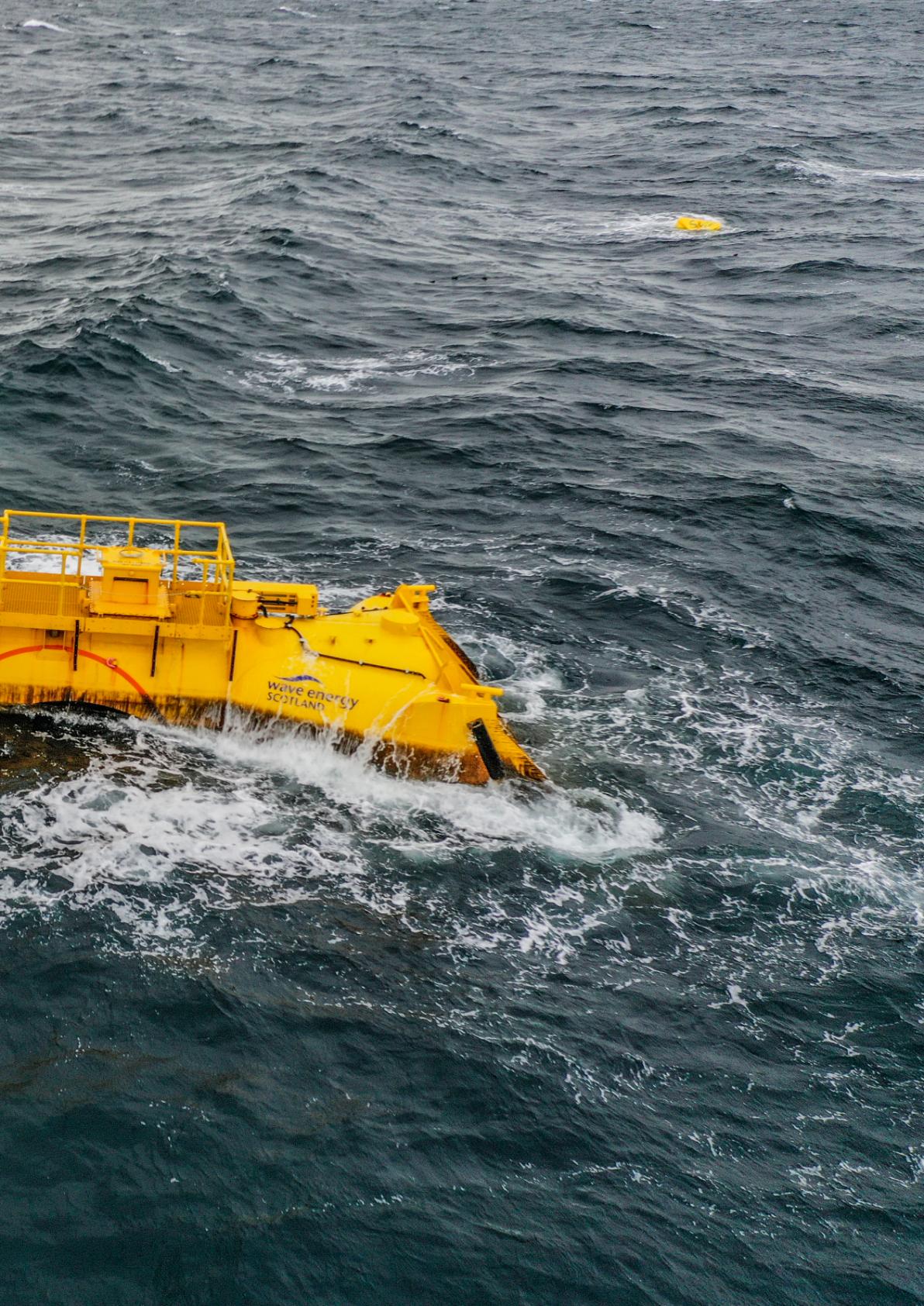
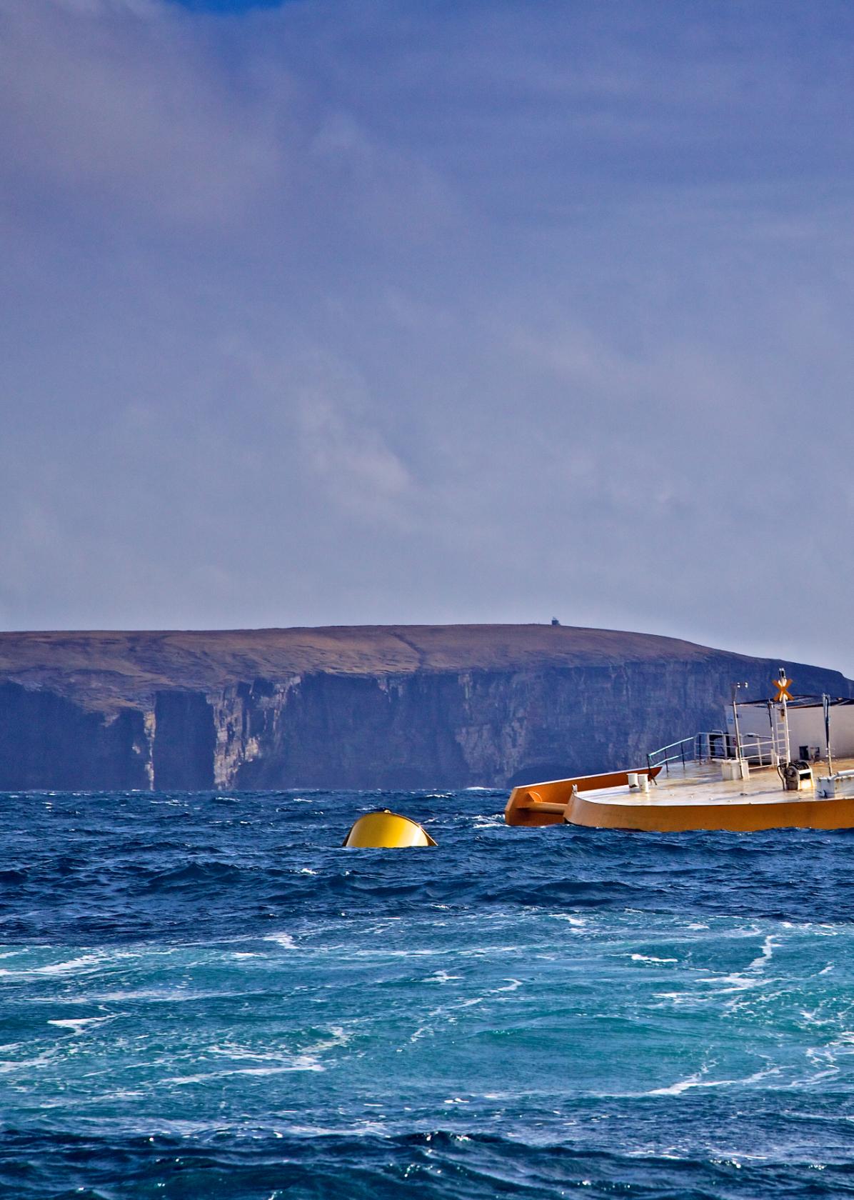
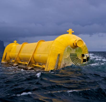
AWS OCEAN ENERGY also delivered their project through the WES NWEC programme. Their device, the Archimedes Waveswing, is a submerged pressure differential WEC which reacts to changes in subsea water pressure caused by passing waves and converts the resulting motion to electricity via its power take-off system. These combine to produce a system that is inherently survivable and reliable whilst providing high levels of efficiency, low cost, and a minimal environmental footprint.
The Waveswing device tested during the NWEC project is approximately half scale, with a full-scale version expected to be rated at approximately 250kW. The prototype arrived in Orkney in January 2022, and during its multiple deployments at the EMEC’s scale wave test site was able to exceed predictions by demonstrating average power capture of over 10 kW, with peaks of 80 kW.
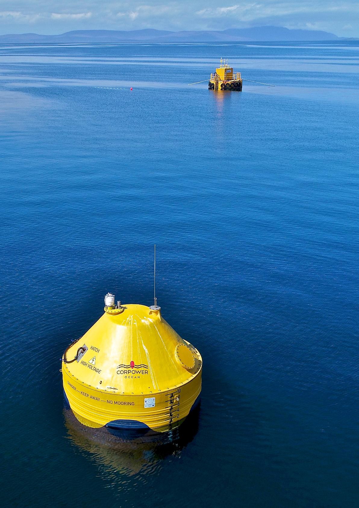
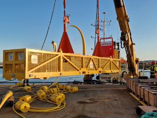
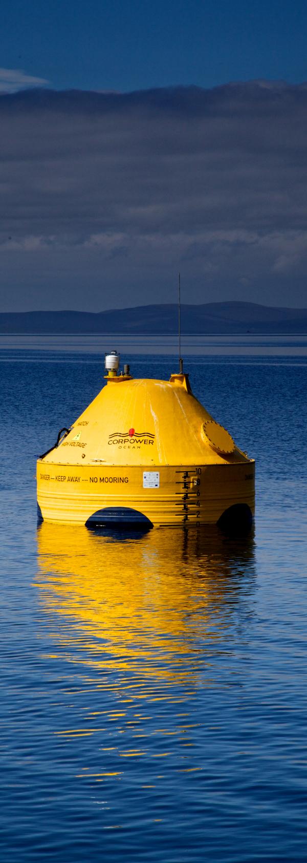
CORPOWER OCEAN tested the C3, a scaled prototype of their novel resonant WEC, at EMEC’s scale wave test site in Scapa Flow in 2018. This was part of a wider project in which WES were supporting the development and implementation of their novel power take-off solution.
The project took advantage of the wider range of services offered by EMEC, who oversaw the dry and wet testing of the machine, ensuring strict quality management and quality assurance of the verification process and provided Performance Statements for both stages. The wet tests also used EMEC’s test support buoy which is able to provide a micro-grid for the WEC to connect into and which simulates a grid-based power supply.
The company are now progressing with demonstration and prototype certification of a full-scale C4 WEC at the site they will use for demonstration of their first wave array in Portugal.
A number of organisations which are no longer active also demonstrated their technologies at the EMEC's full-scale wave energy test site at Billia Croo.
These projects learnt significantly from their prototype testing about
WAVE POWER
the challenges and design opportunities that still exist within wave energy, but unfortunately they did not have adequate funding to address these to enable them to bridge the gap between prototype demonstration and commercial viability.
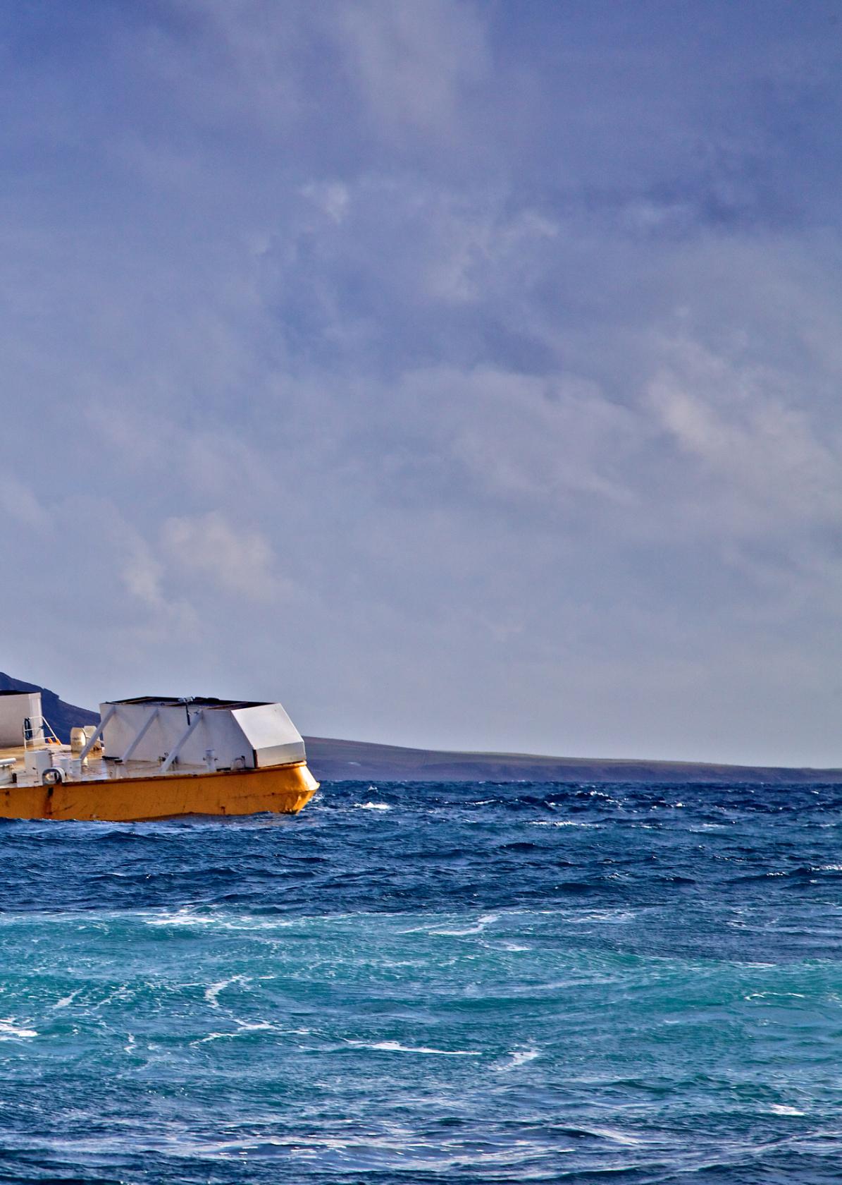
WELLO OY are a Finnish company that developed a rotating mass WEC called the Penguin. It captures rotational
energy generated by the movement of its asymmetrically shaped hull, which rolls, heaves and pitches with each passing wave. This motion was used to accelerate and maintain the revolutions of a spinning flywheel housed inside the hull, which in turn drives an electric generator to produce electricity that is then exported via a subsea cable.
The first incarnation of this device, a 1600 tonne system
Wello Penguin operating at EMEC
Billia Croo , 2017 (Image: Colin Keldie, courtesy of CEFOW
wave energy devices at Billia Croo between 2009 and 2015, with the 315kW Oyster 1 deployed initially, before the significantly larger and optimised 800kW Oyster 800 was installed in 2011 and grid connected in 2012.
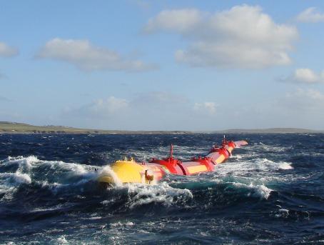
PELAMIS WAVE POWER were the flagbearers of wave energy for
a decade in the early 21st century, having demonstrated their first full-scale prototype, the P1, in between 2004 and 2007, before going on to test the evolution of this between 2010 and 2014. Their technology had multiple tubular sections which moved relative to one another, with this movement being harnessed by hydraulic
rated at 500kW, was first tested intermittently at the Billia Croo test site at EMEC between 2012 and 2015, before a continuous installation took place between 2017 and 2019.
A subsequent iteration of device was briefly tested in the Basque region in 2021. Although the company is no longer trading, there are organisations that are looking to continue to explore the development of the technology.
rams at the joints which in turn drove electrical generators located inside the device.
The P1 was the world’s first offshore wavepower converter to successfully generate electricity intoa national grid, while their next model, the 750kW-rated P2, was larger and
AQUAMARINE POWER developed the Oyster wave power technology to capture energy found in near-shore waves. The oscillating wave surge converter-type WEC consisted of a buoyant, hinged flap attached to the seabed at around 20m depth and half a kilometre from shore.
This flap, which was almost entirely underwater, moved backwards and forwards in the nearshore waves to drive two hydraulic pistons that pushed high pressure water onshore to drive a conventional hydroelectric turbine.
The company deployed and tested two Oyster
deployed as a pair, becoming the first grid-connected wave energy array. Adaptations and evolutions of many innovations first trialled on the P1 and P2 devices, such as the quick connection mechanism and the control methodologies, continue to be used today by the next generation of wave energy technology developers aiming to harness the vast resources available in our seas.
Pelamis P2-002 at EMEC Billia Croo wave test site, 2012 (Image: Pelamis Wave Power)
Aquamarine Power's Oyster 800 wave energy converter in operation, 2013 (Image: Aquamarine Power)
AWS Waveswing installed at EMEC Scapa Flow test site (Image: EMEC)
WAVE POWER
WAVE ENERGY SCOTLAND
WAVE ENERGY SCOTLAND
Wave Energy Scotland (WES) is an organisation funded by the Scottish Government and tasked with addressing the technical challenges facing the wave energy sector in order to accelerate its development and future commercialisation. Since its first technology development programme launched in 2015, WES has run numerous programmes for the Scottish Government and the European Commission.
These use a technology development process that focuses on proving technology and engineering quality to advance the readiness of critical sub-systems for wave energy converters (WECs) as well as full WEC devices, reducing technical and commercial risks, and making the sector more enticing for private investment to reenter.
WES has supported over 300 organisations from industry and academia and delivered 132 R&D projects that developed wave devices, sub-systems, and components. The resulting technologies are now primed to take the next step towards commercialisation and largescale deployment wherever there is a suitable wave energy resource.
WAVE ENERGY OPPORTUNITY
Wave energy is the world’s largest untapped energy resource.
In 2024 the Marine Energy Council (MEC) noted that the Intergovernmental Panel on Climate Change (IPCC) estimated that the potential annual global production to be 29 500TWh, which could provide clean electricity for over 500 million homes. In Scotland, the magnitude of wave resource around the coastlines is huge and offers the perfect environment for building a homegrown marine energy industry. The UK wave resource is estimated at over 100 TWh/yr with more than 60% of this distributed along Scotland’s coast, particularly areas along the exposed swell of the Atlantic.
Waves are caused by the transfer of wind’s kinetic energy to the upper surface of the ocean. The greatest energy is available in open seas and oceans where wind generated waves can develop over great distances.
The energy contained in the motion of the orbiting water particles within the waves is then extracted by WECs, often in a bi-directional motion due to the wave particles having a period of oscillation of the order of around 10 seconds. This contrasts with another form of marine renewables, tidal generation, which extracts energy from current streams that flow in a steady direction over a period of hours.
As research intensifies and novel technologies continue to be developed and transferred from other sectors, the future may see additional device groupings developed depending on the application requirements of each device e.g. for utility scale market or niche market, or an ambitiously novel or a robust reliable system.
CorPower and EMEC microgrid at EMEC Scapa Flow test site, 2018 (Image: Colin Keldie, courtesy of WES
WAVE POWER
The attractiveness of a WEC system is commonly a reflection of its expected levelised cost of energy (LCOE), the sum of the total discounted costs over a device’s lifetime divided by the discounted sum of the energy it is expected to deliver.
Working with the IEA, WES has contributed to defining a number of other metrics that contribute towards LCOE and which can measure the success and attractiveness of WECs and also their individual subsystems. These metrics cover aspects of reliability, survivability, performance and affordability. The metrics applied
to specific WES programmes are the WES Target Outcomes.
WAVE ENERGY FUNDING
Prior to WES, wave energy investment was a huge barrier for developers and public sector support was unstructured. To address this, WES introduced a new funding paradigm – the precommercial procurement model (PCP). This is effectively a technology competition where potential suppliers enter the programme through an open tender and then carry out multiple phases of development that are each separated by a competitive, closed phase gate. The most
promising technologies are then demonstrated in the final phase.
This stage-gated competition has clear goals, effective decision-making processes and strong technical oversight by a team of skilled engineering project managers. This approach is advantageous to developers because it allows for up to 100% of development funding, and advantageous for the public procurers who can quickly and transparently identify the best technologies.
The PCP model means that successful Applicants receive a
AWS Waveswing testing at EMEC Scapa Flow test site (Image: EMEC)
contract for research and development services and not a grant, giving them a higher duty of reporting and evidencing progression to WES than is normal in grant-funded programmes.
THE WES PROGRAMME
The WES programme has delivered a suite of competitive technology development programmes. Each programme typically begins with conceptual design exploration and modelling validation projects in Stage 1, before more thorough engineering design in Stage 2, and a large-scale demonstration in a representative environment in Stage 3.
These programmes have produced a range of commercially attractive innovations, such as the two Stage 3 projects from the Novel Wave Energy Converter (NWEC)
programme: Mocean Energy and AWS Ocean Energy
Both companies successfully demonstrated proof of concept wave energy devices at the European Marine Energy Centre (EMEC) in Orkney, evidencing
the performance, reliability and survivability previously forecast from simulations and small-scale testing in a wave tank.
Following the success and learning of NWEC testing, Mocean Energy subsequently undertook a £2million Renewables for Subsea Power (RSP) project, where their existing WEC was connected to a Halo
underwater battery storage system developed by Aberdeen intelligent energy management
AWS Waveswing at Coplands Dock (Image: Colin Keldie)
Verlume Halo Deployment
WAVE POWER
CorPower and EMEC microgrid at EMEC
Scapa Flow test site (Image: Colin Keldie, courtesy of WES)
specialists, Verlume, and the system was successfully deployed for 12 months at a site 5km east of the Orkney Mainland.
Other partners for this project included TotalEnergies, Shell Technology – Marine Renewable Program, PTTEP, Serica Energy, Harbour Energy, Baker Hughes, Transmark Subsea, and the Net Zero Technology Centre (NZTC).
These devices, and the range of subsystem technologies emerging from the other competitions, have been created by a strong and experienced cohort of organisations, ranging from innovative wave-focused start-ups to Scotland-based engineering companies.
PROGRAMMES
The systems targeted in the programmes run by WES have been identified and prioritised as the areas requiring the most development and/or having the most impact on the future cost of energy for wave energy technologies (at that time). The five funding programmes that have been completed include:
Novel Wave Energy Converter (NWEC): The Novel WEC programme aimed to enhance the power performance of truly novel WEC systems which have not been investigated previously, or existing WEC systems which proposed substantial innovations. As indicated above, 2 organisations from the original 8 entrants reached the final stage and demonstrated their technologies in a representative environment at EMEC in Orkney.
Power Take-Off (PTO): This programme supported a wide range of systems that could convert mechanical to electrical energy with a step change in the capital cost and/or efficiency/performance over current technologies. 5 technologies out of the 17 total participating organisations reached the final stage, demonstrating their solutions at a representative scale in a range of environments, including EMEC, other Scottish marine locations and sophisticated lab-based hardware in the loop test benches.
Quick Connection Systems (QCS): This programme supported projects which aimed to reduce the duration, cost and risk of offshore operations for connecting prototype wave energy converters to their moorings and/or electrical systems. 3 technologies out of the 8 entrants reached the final stage that including testing of the connection system in a representative marine environment, and they are continuing to be supported with their final steps towards commercialisation.
Structural Materials and Manufacturing Processes: This programme investigated if it is possible to make a step change impact in LCOE by constructing typical WEC devices from alternative materials to those traditionally used, such as steel.
The environmental impact of the material proposed was also considered, and helped strengthen the wider case for marine renewables. 10 projects entered the programme, covering themes of concrete, hybrid, elastomers, and composites. 2 projects reached the final stage, with these considering novel concrete jointing methods to allow modular construction and transportation, and the use of marine fenders and synthetic netting as a novel approach to distribute loads on a low-cost displaced volume.
Control Systems: The Control Systems programme sought to
Apollo Installation
design, develop and demonstrate advanced control systems for WECs and sub-systems which could deliver improvements in the WES Target Outcome Metrics.
Once again, 2 projects reached the final stage from an original entry of 13. The two successful projects applied reinforcement learning to enhance the power output of a point absorber, and model predictive control and a Mocean-style attenuator WEC.
CURRENT ACTIVITIES OF WES
The application of a PCP approach in marine renewables is now recognised internationally through IEA-OES and adopted by other governments, including the European Commission which has co-funded WES to deliver the EuropeWave technology development programme.
EuropeWave is a Horizon2020 funded programme, delivered by WES and Ente Vasco de la Energía (EVE), to develop and deploy three pre-commercial WEC systems in Scotland and the Basque region.
WES has continued to explore alternative wave energy generation applications by launching the Direct Generation Concept Design Competition. Direct Generation (DG) is the use
of flexible membranes where movement of elastomer and polymer properties directly transform into electrical energy –this suite of flexible materials could allow for a new class of flexible wave energy conversion without the use of expensive steel structures. This research agenda is a key focus of WES’s R&D strategy and aims to bring this novel concept closer to exploitation.
Wave power also has a complementary generation profile with other technologies, particularly floating offshore wind, enhancing their electrical output since wave is highly predictable, delivers greater supply during winter months when more electricity is needed, and is available when other generation technologies are not.
In the future, there is an opportunity to ‘co-locate’ wave energy converters within offshore wind farms, taking advantage of the fact that wind developers are beginning to explore deployment in locations which have an attractive wave climate while also improving a project’s economic attractiveness through utilisation of shared sea space, infrastructure and supply chain.
An economic study conducted by
WAVE POWER
Offshore Wind Consultants Limited for WES identified that WECs deployed in the vicinity of wind turbines may be attractive to floating offshore wind and wave project developers in the shortterm from both a technical risk and economic standpoint, by possibly enabling up to a 12% reduction of overall costs for both wave and floating offshore wind technologies.
WES is continuing to investigate the techno-economic potential of these co-located arrays through its strategic activities.
Through the success of the WES programme, it has been widely recognised that to avoid funding duplication and to encourage international collaboration, standardisation must be fostered globally. Therefore, WES has been instrumental in steering recommendations for a recognised international evaluation and guidance framework by collaborating on projects with the International Electrotechnical Commission, the US Department of Energy, the European Commission and the International Energy Agency with the shared vision that a standardised suite of metrics will result in the most successful projects.
All the information on the WES programmes and ongoing activities can be found at the recently relaunched WES website, which includes project details, public deliverables, educational content, and historic documents from past wave developers.
A wide variety of WEC concepts have been developed to harness wave energy, but despite differences in their appearance and functionality, they can typically all be categorised into 8 distinct groupings described below:
• ATTENUATOR: An attenuator floats on the surface, oriented parallel with the incoming waves, and consists of at least two bodies which move relative to one another.
The relative pitch motion of these bodies facilitates the mechanical to electrical energy conversion.
• BULGE WAVE: A bulge wave device is a water-filled rubber tube. As a wave passes, it induces a pressure pulse in the internal water which progressively grows in energy along the tube length.
At the end of the tube the energy in this pulse can be converted into electrical power by some means of power conversion technology.
• OSCILLATING WAVE SURGE CONVERTER: An oscillating wave surge converter device is a hinged flap, which moves due to the surge motion of the passing waves before using its inherent buoyancy as a restoring force to return to a neutral position.
• OSCILLATING WATER COLUMN: Oscillating water
columns have an air chamber above the water surface, with air getting sucked in and pushed out through an air turbine as the passing waves change in the internal water level.
• OVERTOPPING: An overtopping device is where the structure forms a reservoir to allow breaking waters to enter and create a head relative to the sea.
As the water exits the structure, it passes through a water turbine to generate electrical power.
• POINT ABSORBER: A point absorber is commonly a singlebody device which generates power by heaving up and down relative to a fixed reference point, such as the seabed.
• ROTATING MASS: Rotating mass systems are a particular geometric design which enhances the yaw and roll movements of the wave energy device to induce a mass to rotate about an axis within the structure.
• SUBMERGED PRESSURE DIFFERENTIAL: The submerged pressure differential device consists of two bodies with a positive internal pressure.
The passing waves vary the internal pressure and volume, resulting in one body moving relative to the other which actuates a method of power conversion.
THE HANDS-ON OCEAN TECHNOLOGY EXHIBITION AND TRAINING FORUM THE HANDS-ON OCEAN TECHNOLOGY EXHIBITION AND TRAINING FORUM TRANSFORM YOUR BUSINESS
3 DAYS HUNDREDS OF SOLUTIONS VISITORS IN 2023 FROM OVER 59 COUNTRIES OF VISITORS FROM OVERSEAS DIRECTOR LEVEL OR ABOVE SPEAKERS, INDUSTRY EXPERTS & THOUGHT LEADERS AUTHORISE OR INFLUENCE BUYING DECISIONS