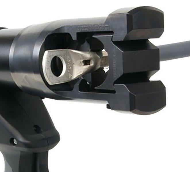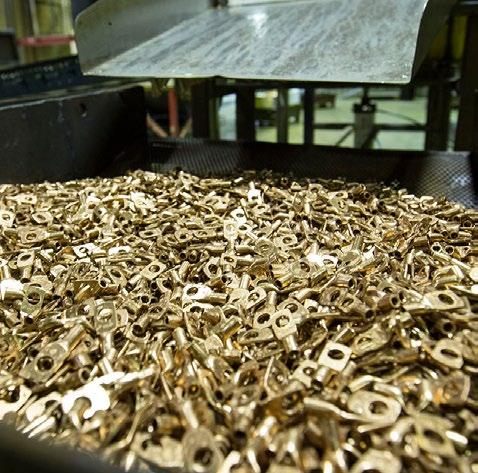


“The business aim of the Elpress Group is to provide, primarily to professional users, qualified material and knowledge concerning electrical applications, with a high level of service and product expertise.”
Head office
Elpress AB
Industrivägen 15
P.O. Box 186
SE-872 24 Kramfors, Sweden
Tel +46 612 71 71 00 sales@elpress.se
Customer support
Tel +46 612 71 71 70 support@elpress.se
Order
Tel +46 612 71 71 70 order@elpress.se
Subsidiaries
Elpress GmbH
Kränkelsweg 24
DE-417 48 Viersen, Germany
Tel +49 2162 93 19-0 sales@elpress.de www.elpress.de
Elpress A/S
Randersvej 16
DK-8600 Silkeborg, Denmark
Tel +45 8681 61 11 salg@elpress.dk www.elpress.dk
Elpress AS
Bruket 31, Pb 79 N-1621 Gressvik, Norway
Tel +47 91 68 55 02 sales@elpress.no www.elpress.no
Elpress Inc., 900 Oakmont Lane, Suite 207, Westmont IL 60559 USA
Tel: +1-331-814 2910 Fax: +1-331-814 2914
sales@elpress.us www.elpress.us
Elpress (Beijing)
Electrical Components Co., Ltd
Rm 1605, Diyang Tower, No. H2 DongsanhuanBei Lu, Chaoyang District, Beijing 100027, P.R. China
Tel:+86 10 5979 6187
Fax:+86 10 6438 5279 info@elpress.com.cn www.elpress.com.cn
Elpress has been developing, manufacturing and marketing complete cable crimping systems for electrical connectors since 1959.
The Elpress Group, consisting of Elpress and ABIKO business areas, is owned by Lagercrantz Group AB. Elpress head office, factory and warehouse are located in Kramfors, Sweden. Subsidiaries Elpress GmbH, Elpress A/S, Elpress AS, Elpress (Beijing) Ltd. and Elpress Inc. with local warehouses in Silkeborg/Denmark, Beijing/China and Chicago/USA.
The information contained in this catalogue is for commercial use to select products only. It is not intended for use in QA instructions, production drawings, instruction manuals or likewise. If such documentation is required, please contact your nearest Elpress representative or Elpress directly. Although every effort has been made to ensure correct and updated information at time of printing, Elpress makes reservation for misprints, wrong or outdated information and changes. Elpress reserve the right to change, update or discontinue products without prior notice.
This catalogue is the property of Elpress. Any reproduction in full, part or of pictures, is forbidden without prior written permission from Elpress AB.


Pre-insulated 0.1 - 6 mm² terminals with associated tools

End terminals 0.14 - 50 mm² with associated tool

Uninsulated terminals 0.15 - 10 mm² with associated tools




Cu terminals 0.75 - 1000 mm²
Al and AlCu terminals 16 - 1200 mm²
Tools for Cu, Al and AlCu terminals
Overhead line connectors
Shearbolt terminals for low and medium voltage
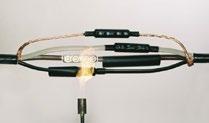
Insulation kit for splicing


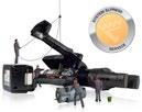

Cutting and insulation stripping tools
Elpress products and services, are designed to minimise environmental impact, to protect limited resources and to take the life-cycle perspective into consideration in connection with:
• Product development.
• Manufacturing.
• Use and withdrawal of products.
Each and every Elpress employee shall prioritize the personal responsibility for safety, quality and the environment within his daily work routine. Information and education will constitute normal activity for increased awareness.
Our suppliers and commissioned partners are chosen and influenced in such a way that they can comply with and add value to our Policy.
Our customers are informed about our environmental dedication and our partners have all the necessary knowledge to assist and advise all parties of the distribution chain and safeguard the proper use, stocking and final disposal of our products.
We continuously evaluate the results of our Policy and openly distribute information on our work and impact on the environment.
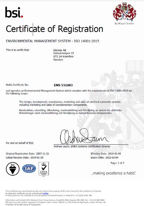
Our environment work has resulted in Elpress being certified to ISO 14001 since 2004. Our certificate, with number EMS 531083, is issued by the internationally recognized BSI, British Standards Institution, of England.
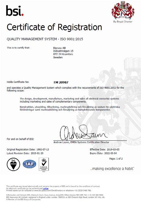
For us, quality means trying all the time to be the best in the business. That’s why we are constantly developing our products, methods and ourselves, since knowledge is perhaps the most important component for achieving the highest quality. Our work on quality has resulted in Elpress being certified to ISO 9001 since 1992.
Our certificate, with number FM20987, is issued by the internationally recognized BSI, British Standards Institution, of England.
There are quite a lot of different test standards and approval routines that may be applied on cable connectors and terminations. Due to this and the variation in contents between standards from different countries one has to make a selection. Elpress had previously applied primarily Swedish, UK and German standards but lately IEC and EN Standards, where the latter rapidly will substitute the old national standards. In many cases, there are also UL, DNV-Det Norske Veritas or other approvals on our products.

IEC - International Electrical Commission - issues international standards which, although not always compulsory, do have strong influence and are used as a basis within the international terminal trade.
DNV - Det Norske Veritas
Elpress KR/KS, KRF/KSF and KRT/KST terminals meet DNV’s rules for classification of ships and Det Norske Veritas’ Offshore Standards. The terminals are approved for installations on ships and mobile “offshore” units.
UL is an American standard which is also internationally accepted. KR/KS, KRF/KSF, KRFS, KRFN, KRT/KST UL approved in accordance with file no. E205350.
System Elpress consists of terminals and tools that are designed and tested together to give a certified crimping result. This ensures that users will feel confident when using our systems, and that a secure connection will be achieved through the proper handling of our products.
Pre-insulated terminals
Elpress ring, fork and pin terminals are made of high-class copper 99.95%. The tab and bullet terminals are made of brass or tin-bronze. All terminals are then electrolytically tin-plated for maximum corrosion protection. The terminal’s neck is brazed and annealed, which means it can be crimped in any direction. The metal in the receptacles’ neck is double folded. This means that the finished terminal has excellent mechanical strength and low resistance.
Insulation material
Elpress insulation sleeves are usually made from halogen-free polycarbonate, PC, which has excellent deformation properties. Furthermore, it maintains its vibration support up to high temperatures. Caution must be exercised in case of alkaline exposure. Some types of terminals have insulation of PA, nylon, which is also halogen-free, or PVC (not halogen free. The colour of the insulation sleeve indicates the cross-sectional area that the terminal is intended for:
Bright yellow sleeve
0.1 - 0.5 mm²
0.25 - 0.75 mm²
sleeve 0.5 - 1.5 mm²
1.5 - 2.5 mm²
4-6 mm²
* or transparent white
The table below shows properties for Elpress pre-insulated terminals insulation. Note the properties are general since the influences of environment, temperature, etc. can affect the terminals. Polycarbonate, PC, and polyamide, PA, are halogen-free, i.e. they do not contain any of the substances fluoride, chlorine, bromide or iodine.
Insulation material Max. temperature Halogen -free Flammability class, UL94
PA (Polyamide)
PC (Polycarbonate)
PVC (Polyvinyl chloride)
105° Yes V0
115° Yes V2
60° No, chlorine V0
Elpress insulation sleeves are usually of the easy-entry type, which means it guides the conductor strands properly into the terminal neck. The risk of back-folded and stray strands, possibly resulting in flash-overs or reduced electrical properties, is therefore eliminated.

Easy-entry.
Elpress pre-insulated terminals are labelled with logo, cross sectional area and any applicable screw diameter to facilitate work and controllability. When contact crimping pre-insulated terminals, Elpress crimping dies/tools leave an imprint in the insulation sleeve so that all crimped terminals can be inspected retrospectively in accordance with the requirements of many standards.
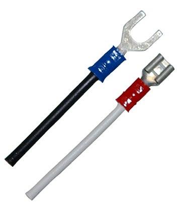
Designation example
Cat no. A1532R (E, FLS, G etc.)
A = pre-insulated
15 = cross sectional area (1.5 mm2)
32 = characteristic size (Hole 3.2 mm)
E = end connectors
FLS = receptacles, rolled type
FLSF = receptacles, fully insulated rolled type
FLSH = multiple tabs, rolled type (piggy back)
FLST = receptacles, rolled type, tin-bronze
G = fork terminals
GB = flanged fork terminals
H = tabs (male)
HA = bullets (male)
HO = sockets (female)
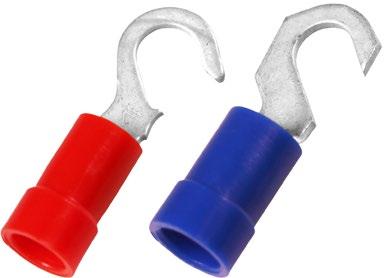
K = hook terminals
PSK = parallel connectors
R = ring terminals
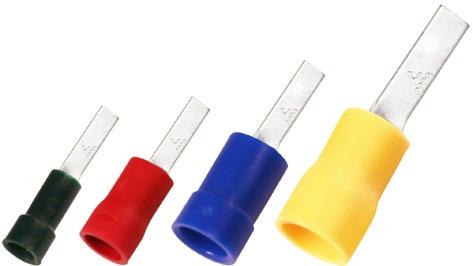
SF = blade terminals
SFB = blade terminals, flanged
SFK = blade terminals, short pin
SFL = blade terminals, long pin
SFN = blade terminals, with tab
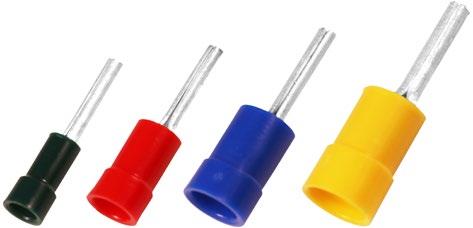
SR = pin terminals
SRK = pin terminals, short pin
SK = through connectors
SKW = through connectors with heat shrink insulation
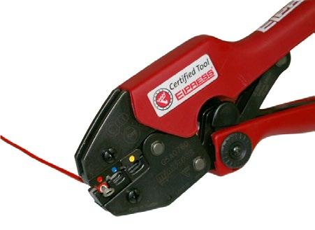
In the development of a mechanical crimping tool at Elpress, we strive for the best quality and ergonomics in the actual tool, and the best characteristics in the crimped terminal. The tools have a built-in locking system (not the hobby tools) that ensures that the entire crimping process is completed - a prerequisite for professional and quality-assured work.
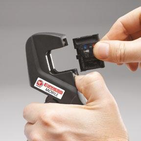
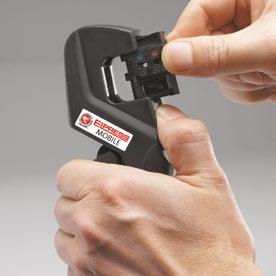
Elpress Mobile, professional tool with interchangeable dies for the installer or service technician.
With the unique Miniforce tools, a new level has been established regarding ergonomic adaptation to the user and low force requirements. This has resulted in a decrease in the grip forces by up to 45% and is the result of an advanced development process where minimisation of the risks of work-related injuries and the best ergonomics have been the deciding factors.
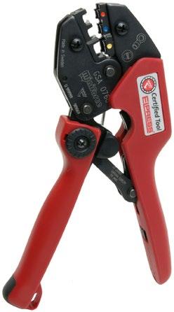
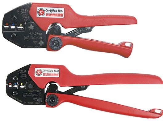
Miniforce type C has longer handles to facilitate two-handed operation, which is often a simple and natural way to reduce the loads. Electrical crimping tools and terminals together constitute a contact crimping system where crimping results are continuously checked against the requirements of established standards such as IEC 60352-2, SEN 245010, DIN 46429, IEC 61238-1 etc. Many of the manual tools have symmetrical crimp positions that make it possible to work from both sides - something that is important for left-handed users. The tools in the Miniforce, D and 50 series are made of very high-grade hardened steel with a black oxide finish and are laser marked.
The certificate that accompanies the tool serves several functions:
• crimping tools are often directly introduced upon procurement in a quality management system. The tool’s status at procurement shall of course be the first thing noted, to then be followed by regular checks where potential changes can be discovered and addressed.
• the certificate shows that each individual tool meets the requirements of the tool’s basic specifications.
• the certificate states what the most important characteristics are that shall be followed up.
Elpress’ service department offers the possibility of continued follow-up of the quality of the tools.
For quality assurance of our tools, we certify the manufacture of our crimping tools, both hand tools, type Gxx, i.e. Miniforce tools, and type Dxx.

Certification of the crimping tools means that each individual tool is documented at the final assembly and inspection stage with respect to:
• handle pre-load, which is the force needed to ensure that the lock, which prevents a crimp from being interrupted, is not released too early.
• crimp die nest heights, i.e. the maximum height measurements which can be measured in each indentation with the dies pressed together.

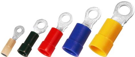
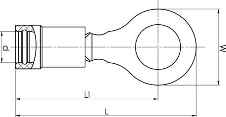
• Material: Cu 99.95%, tin plated Cu/Sn, brazed neck.
• PC insulation has easy-entry, PC and PA are halogen-free.
0,1-0,5
M2,5
0,1-0,5 26-20 A0553R M5 8 2 19 16 0,5 6 DSA0115 PA
0,25-0,75
0,25-0,75 24-20 A0843R M4 7,5 3,2 21 17,5 0,5 7 DSA0115 PC Yes 100
0,25-0,75 24-20 A0853R M5 9 3,2 22 17,5 0,5 7 DSA0115 PC Yes 100
0,5-1,5 20-16 A1532R M3 5,5 4 19 16 0,7 7 GSA0760 PC Yes 100
0,5-1,5 20-16 A1537R M3,5 6 4 19 16 0,7 7 GSA0760 PC Yes 100
0,5-1,5 20-16 A1543R M4 7 4 20,5 17 0,7 7 GSA0760 PC Yes 100
0,5-1,5 20-16 A1553R M5 9 4 22,5 18 0,7 7 GSA0760 PC Yes 100
0,5-1,5 20-16 A1565R M6 11 4 26,5 21 0,7 7 GSA0760 PC Yes 100
0,5-1,5 20-16 A1585R M8 14 4 27,5 20 0,7 7 GSA0760 PC Yes 100
0,5-1,5 20-16 A1510R M10 16,5 4 30,5 22 0,7 7 GSA0760 PC Yes 100
1,5-2,5 15-14 A2532R M3 5,5 4,5 19 16 0,8 8 GSA0760 PC Yes 100
1,5-2,5 15-14 A2537R M3,5 6,2 4,5 19 16 0,8 8 GSA0760 PC Yes 100
1,5-2,5 15-14 A2543R M4 7 4,5 21 17,5 0,8 8 GSA0760 PC Yes 100
1,5-2,5 15-14 A2553R M5 9 4,5 23 18 0,8 8 GSA0760 PC Yes 100
1,5-2,5 15-14 A2565R M6 11 4,5 26 20,5 0,8 8 GSA0760 PC Yes
1,5-2,5 15-14 A2585R M8 14 4,5 28 21 0,8 8 GSA0760 PC Yes 100
1,5-2,5 15-14 A2510R M10 16,5 4,5 30,5 22 0,75 8 GSA0760 PC Yes 100
1,5-2,5 15-14 A2513R M12 18 4,3 34 26 0,75 8 GSA0760 PA Yes 100
4-6 12-10 A4643R M4 7,8 6,4 24,5 20,5 1 9 GSA0760 PC Yes 100
4-6 12-10 A4653R M5 9 6,4 25 20,5 1 9 GSA0760 PC Yes 100
4-6 12-10 A4665R M6 11 6,4 28,5 23 1 9 GSA0760 PC Yes 100
4-6 12-10 A4685R M8 14 6,4 30,5 23,5 1 9 GSA0760 PC Yes 100
4-6 12-10 A4610R M10 17 6,4 34 25,5 1 9 GSA0760 PC Yes 50
4-6 12-10 A4613R M12 19,2 6,8 40 31 1 9 GSA0760 PC Yes 50
t = palm thickness, s = strip length
• Material: Cu 99.95%, tin plated Cu/Sn, brazed neck.
• PC insulation has easy-entry, PC and PA are halogen-free.
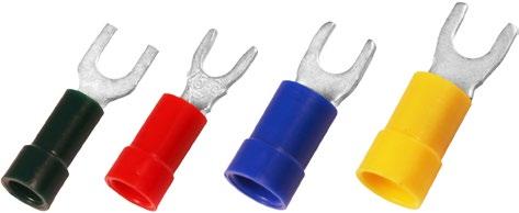
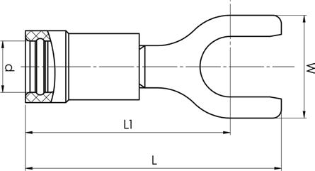
0,1-0,5 26-20 A0532G M3
0,25-0,75 24-20 A0832G M3
0,25-0,75 24-20 A0837G M3,5 6,2 3,2 21 17,5 0,5 7 DSA0115
0,25-0,75 24-20 A0843G M4 6,2 3,2 21 17,5 0,5 7 DSA0115
0,5-1,5 20-16 A1532G M3 5,5 4 19 16 0,7 7 GSA0760
0,5-1,5 20-16 A1537G M3,5 6,2 4 21 17,5 0,7 7 GSA0760 PC Yes 100
0,5-1,5 20-16 A1537GS M3,5 5,5 4 21,2 17 0,7 7 GSA0760 PC Yes 100
0,5-1,5 20-16 A1543G M4 7 4 21 17,5 0,7 7 GSA0760 PC Yes 100
0,5-1,5 20-16 A1553G M5 9 4 22,5 18 0,7 7 GSA0760 PC Yes 100
0,5-1,5 20-16 A1565G M6 11 4 26,5 21 0,7 7 GSA0760 PC Yes 100
1,5-2,5 16-14 A2532G M3 5,5 4,5 18 15 0,8 8 GSA0760 PC Yes 100
1,5-2,5 16-14 A2537G M3,5 6,2 4,5 21 17,5 0,8 8 GSA0760 PC Yes 100
1,5-2,5 16-14 A2537GS M3,5 5,5 4,5 21,2 17 0,8 8 GSA0760 PC Yes 100
1,5-2,5 16-14 A2543G M4 7 4,5 21 17,5 0,8 8 GSA0760
1,5-2,5 16-14 A2553G M5 9 4,5 23 18 0,8 8 GSA0760 PC Yes 100
1,5-2,5 16-14 A2565G M6 11 4,5 25 19,5 0,8 8 GSA0760 PC Yes 100
4-6 12-10 A4643G M4 7,8 6,4 24 20 1 9 GSA0760
4-6 12-10 A4653G M5 9 6,4 25 20,5 1 9 GSA0760
4-6 12-10 A4665G M6 11 6,4 27 21,5 1 9 GSA0760
4-6 12-10 A4685G M8 14 6,4 30 23 1 9
4-6 12-10 A4610G M10 18 6,4 36 27,5 1 9
t = palm thickness, s = strip length
• Material: Cu 99.95%, tin plated Cu/Sn, brazed neck.
• PC insulation has easy-entry, PC is halogen free.
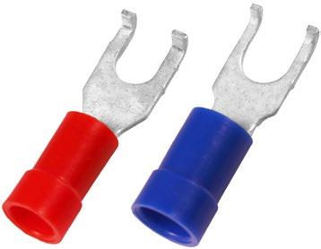
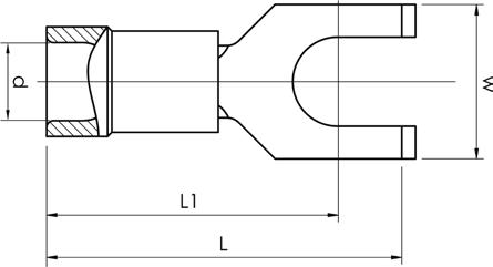
0,5-1,5 20-16 A1537GB M3,5 6,2 4 21 17,5 0,7
0,5-1,5 20-16 A1543GB M4 6,2 4 21 17,5 0,7 7
1,5-2,5 16-14 A2543GB M4 6,2 4,5 21 17,5 0,8 7 GSA0760 PC
1,5-2,5 16-14 A2553GB M5 9 4,5 22,5 17,5 0,8 7 GSA0760 PC
t = palm thickness, s = strip length
• Material: Cu 99.95%, tin plated Cu/Sn, brazed neck.
• PC insulation has easy-entry, PC is halogen free.

t = palm thickness, s = strip length
• Material: Cu 99.95%, tin plated Cu/Sn, brazed neck.
• PC insulation has easy-entry, PC and PA are halogen-free.
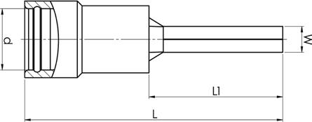
26-20 A0514SR
A0819SR
0,25-0,75 24-20 A0819SRK 1,8 3,2 18,5 8,5 7 DSA0115 PC
0,5-1,5 20-16 A1519SR 1,7 4 22 12 7 GSA0760
0,5-1,5 20-16 A1519SRK 1,7 4 18,5 8,5 7 GSA0760
1,5-2,5 16-14 A2519SR 1,9 4,5 21,5 11,5 8 GSA0760
1,5-2,5 16-14 A2519SRK 1,9 4,5 18,5 8,5 8 GSA0760 PC
4-6 12-10 A4630SR 2,7 6,4 27 14 9 GSA0760
s = strip length
• Material: Cu 99.95%, tin plated Cu/Sn, brazed neck.
• PC insulation has easy-entry, PC is halogen free.
16-14
4-6 12-10 A4640SF 4 6,8 27,5 13,5 1
12-10 A4645SFB
t = palm thickness, s = strip length
• Material: Cu 99.95%, tin plated Cu/Sn, contact sleeve of Cu pipe
• Halogen-free PC insulation without Easy-entry.
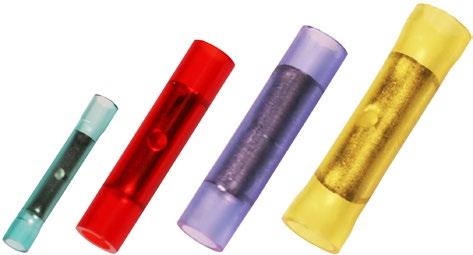

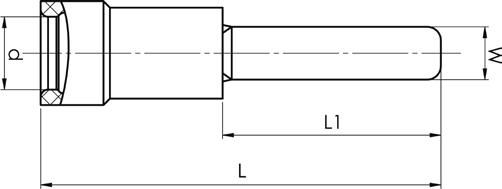
0,25-0,75 24-20 A0824SK 2,9 24,5 7 DSA0115 PC
0,5-1,5 20-16 A1525SK 3,4 24 7 GSA0760 PC No
1,5-2,5 16-14 A2527SK 4,3 26 8 GSA0760 PC No
4-6 12-10 A4652SK 6,5 33 9 GSA0760 PC No
s = strip length
• Material: Cu 99.95%, tin plated Cu/Sn, contact sleeve of Cu pipe.
• Insulation of halogen-free PA, hot melt adhesive inside the insulation.
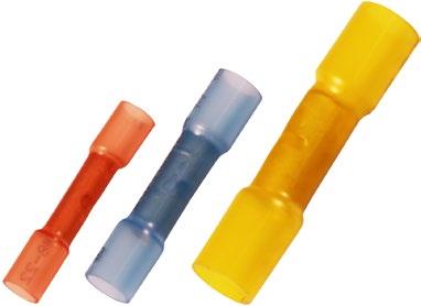
0,5-1,5 20-16 A1535SKW 3,7 31,5 8 GSW0560C PA 25
1,5-2,5 16-14 A2535SKW 4,6 31,5 8 GSW0560C PA 25
4-6 12-10 A4650SKW 6,5 37,5 9 GSW0560C PA 25
s = strip length
After crimping and heating with a hot air gun, a water proof terminal, glued to the cable and the connector, is achieved.
• Material: Cu 99.95%, tin plated Cu/Sn, contact sleeve of Cu pipe.
• Insulation of halogen-free PA.
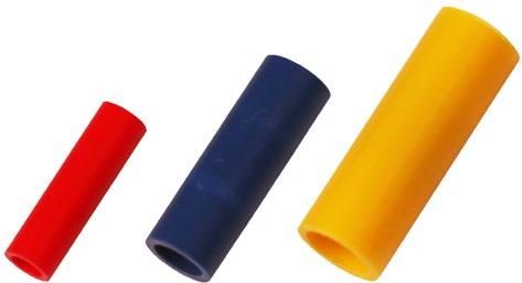
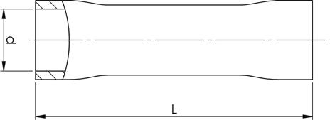
0,5-1,5 20-20 A1515PSK 3,2 17 7 GSA0760 PA 100
1,5-2,5 16-16 A2517PSK 4 17 8 GSA0760 PA 100 4-6 12-10 A4634PSK 5,6 21 9 GSA0760 PA 100
s = strip length
Type PSK must be crimped with GSA0760 (C) and with two crimps.
• Material: brass, tin plated Cu/Sn, brazed neck.
• PC and PA insulation have easy-entry, PC and PA are halogen-free.
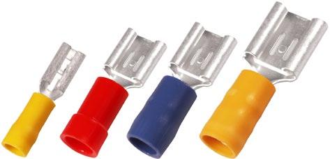
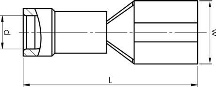
0,5-1,5 20-16 A1507FLS 7,6 4 20,5 7 6,3x0,8 GSA0760 PC
0,5-1,5 20-16 A1507FLST 7,6 4 20,5 7 6,3x0,8 GSA0760 PC Brazed Yes Tin
1,5-2,5 16-14 A2505FLS5 5,6 4,5 20 8 4,8x0,5 GSA0760 PA Brazed Yes Brass, Cu/Sn
1,5-2,5 16-14 A2505FLS8 5 3,9 19,5 8 4,8x0,8 GSA0760 PA Brazed Yes Brass, Cu/Sn
1,5-2,5 16-14 A2507FLS 7,6 4,5 20,5 8 6,3x0,8 GSA0760 PC Brazed Yes Brass, Cu/Sn
1,5-2,5 16-14 A2507FLST 7,6 4,5 20,5 8 6,3x0,8 GSA0760 PC Brazed Yes Tin
4-6 12-10 A4607FLS 7,6 6,4 24 9 6,3x0,8 GSA0760 PC Brazed Yes Brass, Cu/Sn
4-6 12-10 A4609FLS 10,9 6,6 30,1 9 9,5x1,2 GSA0760 PA Reinforcement
s = strip length
• Material: brass/Cu, tin plated Cu/Sn.
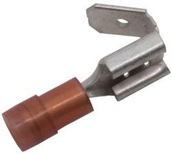

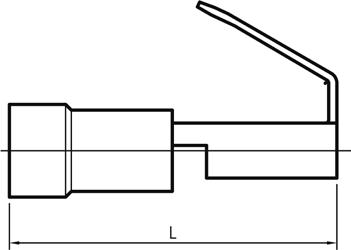
2.5 mm²

20-16
1,5-2,5 16-14 A2507FLSH 6,9 3,9 22 8 6,3x0,8 PA
s = strip length
• Material: brass, tin plated Cu/Sn, brazed neck.
• PC and PA insulation has easy-entry, PC and PA are halogen-free.
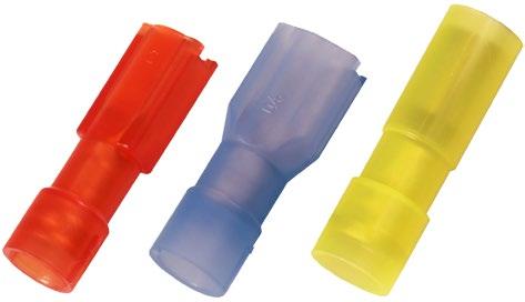
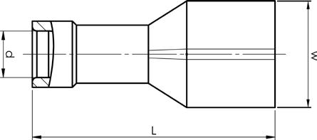
0,5-1,5
20-16
0,5-1,5 20-16
1,5-2,5 16-14 A2505FLSF5 7,2 4,5 19,5 8 4,8x0,5 PA
1,5-2,5 16-14 A2505FLSF8 7 3,9 19,5 8 4,8x0,8 PA
1,5-2,5 16-14 A2507FLSF 8,8 4,5 21,3 8 6,3x0,8 PC
4-6 12-10 A4607FLSF 9,2 5,4 26 9 6,3x0,8 PA
s = strip length
• Material: brass, tin plated Cu/Sn, brazed neck.
• PC and PA insulation have easy-entry, PC and PA are halogen-free.
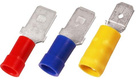
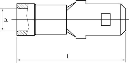
0,5-1,5 20-16 A1507H 4,1 22 7 6,3x0,8 PC
1,5-2,5 16-14 A2507H 5 22,5 8 6,3x0,8 PC Brazed
4-6 12-10 A4607H 6,6 24,5 9 6,3x0,8 PA Reinforcement sleeve No 100
s = strip length
• Material: Cu, tin plated Cu/Sn.
• Insulation of halogen-free PA. Easy-entry.
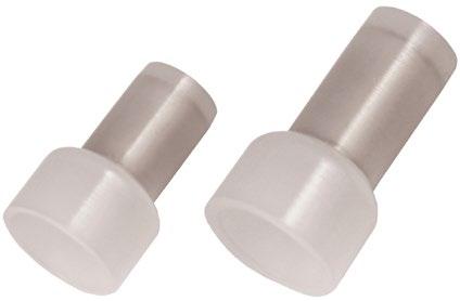
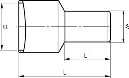
1-3 18-13 A2500E 6,4 15,2 8 8 GSA0760 PA
4-6 12-10 A4600E 9,2 17,7 9 9
s = strip length
• Material: brass/Cu, tin plated Cu/Sn.
• PC insulation has easy-entry, PC and PA are halogen-free.
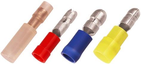
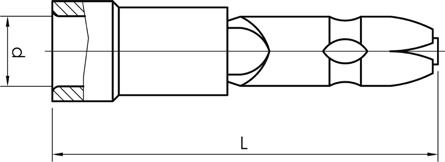
0,25-0,75 24-20 A0802HA 3,1 26 7 2,0 DSA0115 PA Reinforcement
0,5-1,5 20-16 A1504HA 4 22 7 4,0 GSA0760 PC
1,5-2,5 16-14 A2505HA 4,3 20,7 8 5,0 GSA0760 PVC
4-6 12-10 A4605HA 6,6 25,7 9 5,0 GSA0760 PA
s = strip length
• Material: brass/Cu, tin plated Cu/Sn.
• PC insulation has easy-entry, PC and PA are halogen-free.
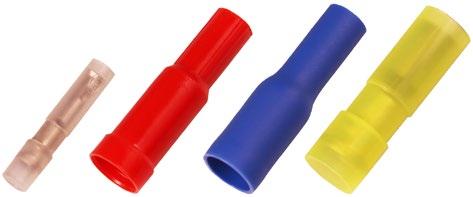
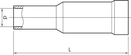
0,25-0,75 24-20 A0802HO 3,1 24,5 7 2 DSA0115 PA
0,5-1,5 20-16 A1504HO 4 25 7 4 GSA0760 PC
1,5-2,5 16-14 A2505HO 3,2 25 8 5 GSA0760 PVC Reinforcement sleeve No Brass/Cu, Cu/Sn
4-6 12-10 A4605HO 5,7 27 9 5 GSA0760 PA Reinforcement sleeve No
s = strip length
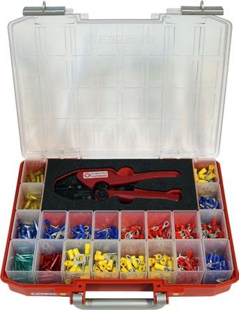
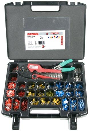
RPL605 is a complete assortment box for professional work, containing terminals and tools.
Properties:
• certified crimping tool GSA0760, crimp area 0.5-6 mm²
• stripping tool SCT001, cuts and strips 0.5-6 mm²
• 605 x Elpress pre-insulated 0.5-6 mm² terminals
Elpress assortment box designed for electromechanical and service workshops.
Properties:
• box made of ABS plastic, inserts made of polystyrene
• 29 compartments
• 997 pre-insulated 0.5-6 mm² terminals
• 4 connection blocks
• crimping tool GSA0760 Miniforce
• stripping tool SCT001
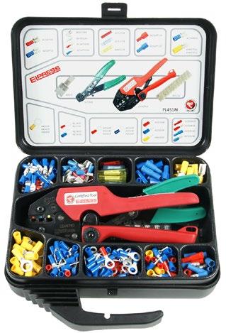
Elpress assortment box for professional use.
Properties:
• box made of polypropylene, insert made of polystyrene
• 11 compartments
• 346 pre-insulated 0.5-6 mm² terminals
• 3 connection blocks
• crimping tool GSA0760 Miniforce
• stripping tool SCT001
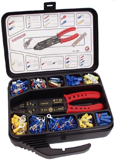
Elpress assortment box designed for hobby use.
Properties:
• box made of polypropylene, insert made of polystyrene
• 11 compartments
• 346 pre-insulated 0.5-6 mm² terminals
• 3 connection blocks
• crimping tool hobby T50, which contact crimps, cuts and strips up to and including 6 mm² and cuts M2.5-M5 screws
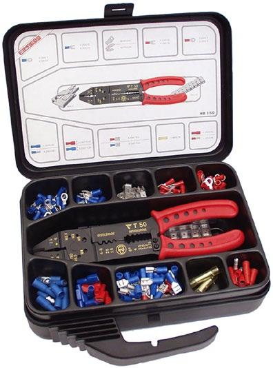
Elpress assortment box designed for hobby use.
Properties:
• box made of polypropylene, insert made of polystyrene
• 11 compartments
• 147 pre-insulated 0.5 - 6 mm² terminals
• 2 connection blocks
• crimping tool hobby T50, which contact crimps, cuts and strips up to and including 6 mm² and cuts M2.5-M5 screws
Properties:
• made of high-grade steel with semi-soft handles
• crimping positions are clearly marked
• the tools do not have a locking function
• cuts up to and including 6 mm²
• strips up to and including 6 mm²
• cuts screws M2.5-M5

Crimp geometries
Special properties:
• contact crimps pre-insulated 0.5 - 6 mm² terminals and tab crimps uninsulated 1.5 - 6 mm² terminals
• red handle

Crimp geometries
Special properties:
• contact crimps pre-insulated 0.5 - 6 mm² terminals and roll crimps uninsulated 0.5 - 2.5 mm² terminals
• yellow handle

Crimp geometry
Special properties:
• roll crimps uninsulated 0.5 - 6 mm² terminals
• green handle

Properties:
• crimping positions are clearly marked
• adjustable for changes after long use
• tested with Elpress terminals
• locking function that ensures a complete crimp
• emergency release if the crimping process has to be interrupted
• unique design that makes the tools thin and versatile
• minimal muscle strength required for complete crimp
• suitable for both right and left-handed users
• withstands at least 50,000 crimps supplied with certificate for basic quality monitoring
Tested and certified mechanical hand tool for symmetrical crimping of pre-insulated terminals 0.14-1.5 mm².
Special properties:
• easy to check red die nests easily with die nest gauge, ESAQ0760 mm²
0,14-1,5 26-16

Tested and certified mechanical hand tool for symmetrical crimping of pre-insulated terminals 0.5-2.5 mm².
Special properties:
• die nests are easily checked with die nest gauge, ESAQ0760
0,5-2,5 20-14
Oval 0,449 192 66
Go/no-go gauge for inspection of die nests in the following tools: DSA0115, DSA0725, GSA0760(C), GSEA0340C.
Special properties:
• handle part Ø 8 mm
• easy to check tool die nest
• The go and no go dimensions are checked in the die nests upon calibration. Contact Elpress for more information on calibration and quality management
mm² AWG
Net weight (kg) Shaft ø Length mm
0,5-2,5 20-14 ESAQ0760 0,024 8 55
Tool Die nests
DSA0115
DSA0725
GSA0760(C)
GSEA0340(C)

Properties:
• locking function which only releases once crimping is complete
• emergency release if the crimping process has to be interrupted
• symmetrical and clearly marked crimping positions
• adjustable for changes after long use
• tested with Elpress terminals
• unique mechanism that reduces maximum handle force from 450 N right down to 250 N (model C)
• ergonomic handle suitable for all users
• maximises the quality of work
• reduces the risk of occupational injuries
• light and versatile design without sacrificing on strength
• model C has extra long handles for the use of two hands
• withstands at least 80,000 crimps
• supplied with certificate for basic quality monitoring

Crimp geometries
Tested and certified mechanical Miniforce hand tool for crimping pre-insulated terminals 0.5-2.5 mm² as well as pre-insulated and uninsulated end sleeves 0.25-4 mm².
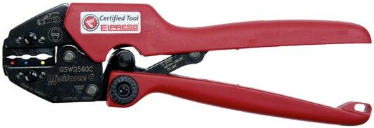
Crimp geometry
Tested and certified mechanical Miniforce hand tool for crimping 0.5-6 mm² through connectors with heat shrink insulation of the SKW type.
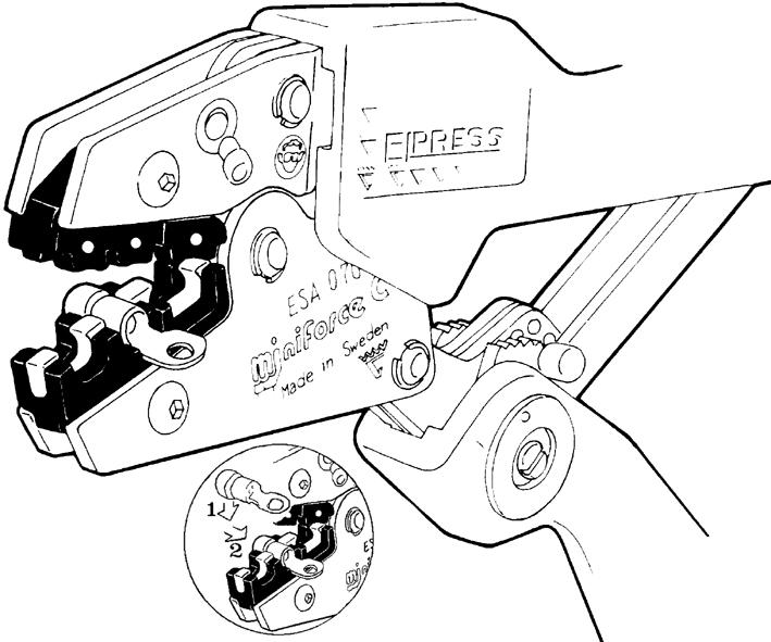
Follow procedures (1) and (2) when attaching the terminal in the locator on tool GSA0760(C).
Crimp geometry
Tested and certified mechanical Miniforce hand tools for symmetrical crimping of pre-insulated terminals 0.5-6 mm².
Special properties:
• locator that holds the terminal in the right position when crimping and facilitates work in, for example, tight spaces
• die nests are easily checked with die nest gauge, ESAQ0760
Properties:
• Li-ion battery powered (10.8 V and 2 Ah), charging time about 40 min
• very good accessibility and ergonomics
• service and installation tools
• fast crimping process 2 – 4 sec
• approximately 230 crimps/battery charge
• dies for the tool sold separately
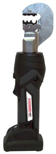
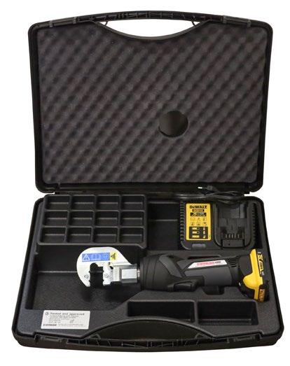
Elpress mini tool with a sleek design with a high performance Li-Ion battery that facilitates your work with its improved battery capacity. Crimping force max. 13 kN. 1 x Li-ion battery and charger included.
Properties:
• one-handed operation for easy control of all tool functions
• durable crimping head for long service life
• optimal crimping thanks to parallel-moving dies
• easy to use due to its low weight
• high-performance 12 V Li-Ion battery – with indication of charge status
• open head, rotating
• easy and comfortable to use one handed thanks to its ergonomic 2-component housing with grip-friendly protection
• automatic return of dies when crimping is complete mm² (Cu) AWG (Cu)
Charger: 230VAC 0,25-50 24-1/0
Charger:
without Battery/ Charger

Elpress mini tools with intuitive PowerSense function combine the benefits of manual crimping tools with the benefits of battery-powered hydraulic crimping tools.
Crimping force max. 15 kN. 1 x Li-ion battery and charger included.
Properties:
• one-handed operation for easy control of all tool functions
• electronic control with locking function and monitoring for complete closure of the jaws
• safety loop used as fall protection when used outdoors
• motor protection ensures safety in case of overload
• easy and comfortable to use one handed thanks to its ergonomic 2-component housing with grip-friendly protection
• very low weight and fast crimping process for maximum efficiency
• powerful driving technology allows for easy crimps
• high-performance 12 V Li-Ion battery – with indication of charge status
• LED work lighting
• Die pair SA0760 comes with the tool
without Battery/Charger
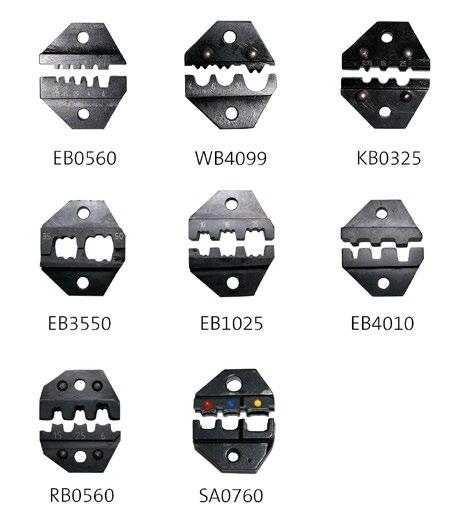
0,5-6 20-10 SA0760 Oval 0,05 Pre-insulated terminals 0,25-2,5 22-14 KB0325 Tab 0,039 Uninsulated terminals 4-10 12-8 WB4099 W 0,05 Uninsulated terminals 0,5-6 20-10 RB0560 Roll 0,05 Uninsulated terminals
0,5-6 20-10 EB0560 Trapezoid 0,057 End sleeves 4-10 12-8 EB4010 Trapezoid 0,05 End sleeves 10-25 6-4 EB1025 Trapezoid 0,05 End sleeves 35-50 2-0 EB3550 Trapezoid 0,05 End sleeves
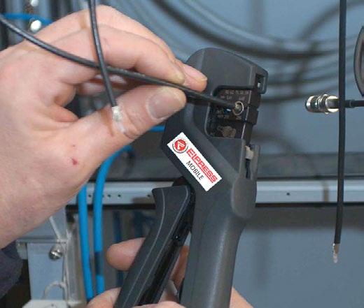
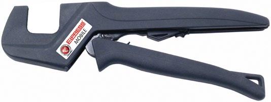
Professional contact crimping tool with interchangeable dies for the installer or service technician.
Properties:
• reliable, safe, economic and ergonomic tools
• parallel-moving crimping movement with 10 kN crimping force, tested for 20,000 crimps
• change crimping dies quickly and easily in one operation
• the crimping dies are kept together in pairs and stored in custom holders
• wide selection of dies allows you to use one tool frame for 19 different crimping applications!
Mobile hand tool (frame only). Dies are supplementary.
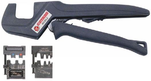
Elpress Mobile + dies OAA0525 and OEB0210.
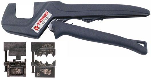
Elpress Mobile + dies OMP45 and OCC1113.
Mobile hand tool with two interchangeable dies:
• Die OAA0525 for crimping pre-insulated 0.5 - 2.5 mm² terminals.
• Die OEB0210 for crimping end sleeves 0.25 - 10 mm².
• The tool comes with associated dies in blister packaging.
Mobile hand tool with two interchangeable dies:
• OMP45 for crimping modular plug RJ45.
• OCC1113 for crimping coaxial contacts RG58, RG59, RG62 and RG71.
• The tool comes with associated dies in blister packaging.
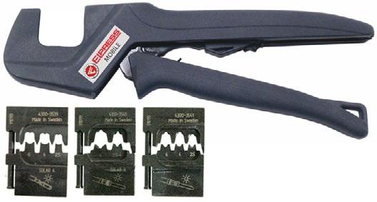
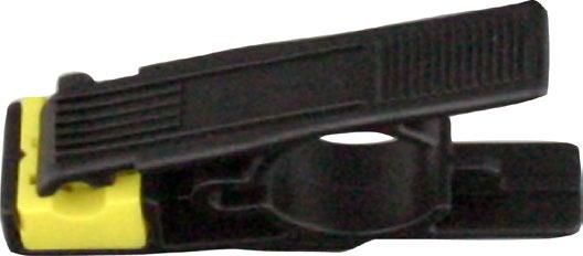
Mobile hand tool with three interchangeable dies and cable stripper LOKE for stripping solar panel cable with extra thick insulation:
• OMS4, roll crimping of contacts with sleeve Ø 4 mm, 2.5 - 6.0 mm².
• OMS3, square crimping of contacts with sleeve Ø 3 mm, 2.5 - 6.0 mm².
• OMSL, square crimping of contacts, 2.5 - 6.0 mm².
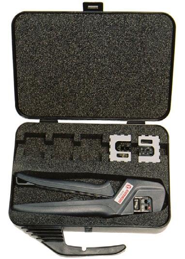
Box for the mobile tool with room for the tool as well as 5-6 associated dies. Tools and dies are ordered separately.
Name
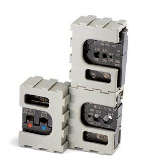
All dies have the same quick and easy way of being inserted into the tool frame. The dies are kept together in pairs and supplied in a cassette that can be docked to other cassettes.
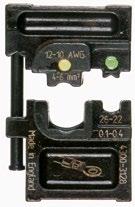
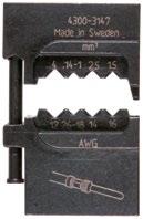
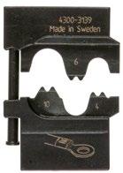
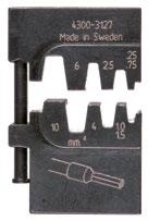
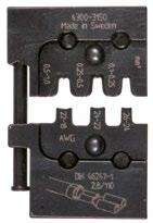
OAA0160
Crimping die for Elpress MOBILE tool for asymmetric crimping of pre-insulated terminals 0.1-4 mm2 and 4-6 mm2 AWG 11-9
OPB0140
Crimping die for Elpress MOBILE tool for crimping global power connectors, GPC connectors.
OWB4099
Crimping die for Elpress MOBILE tool for W crimping of uninsulated terminals 4-10 mm2 AWG 11-7.
OEB0210
Crimping die for Elpress MOBILE tool for crimping end sleeves 0.2510 mm2 AWG 24-7.
ORB0110
Crimping die for Elpress MOBILE tool for roll crimping uninsulated terminals 0.1-1 mm2 AWG 26-17.
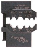
OFO5432
Crimping die for Elpress MOBILE tool for crimping fibre optic contacts.
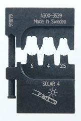
OMS4
Dies for Mobile tools for roll crimping contacts with sleeve diameter 4 mm, 2.5-6.0 mm2 AWG 13-19.
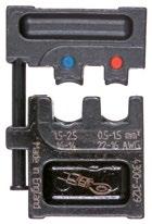
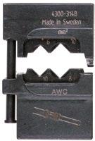
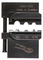

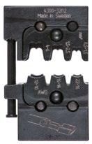
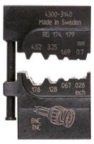
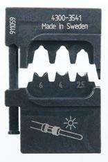
OAA0525
Crimping die for Elpress MOBILE tool for asymmetric crimping of pre-insulated terminals
0.5-2.5 mm2 AWG 20-13.
OPB6099
Crimping die for Elpress MOBILE tool for crimping global power connectors, GPC connectors.
OKB0725
Crimping die for Elpress MOBILE tool for punch crimping uninsulated terminals 0.75-2.5 mm2 AWG 18-13.
OEB1625
Crimping die for Elpress MOBILE tool for crimping end sleeves 16-25 mm2 AWG 5-3.
ORB0560
Crimping die for Elpress MOBILE tool for roll crimping uninsulated terminals 0.5-6 mm2 AWG 20-9.
OCC0908
Crimping die for Elpress MOBILE tool for crimping coaxial contacts RG174, 179.
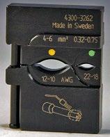
OSW0360
Crimping die for Elpress MOBILE tool for crimping through connectors with heat shrink insulation
0.3-0.75 mm2 and 4-6 mm2 AWG 11-9.
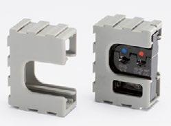
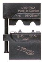
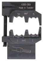
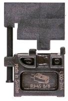
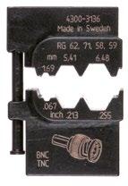
OMSL
Die for square crimping contacts 2.5-6.0 mm2 AWG 13-9.
OKB0560
Crimping die for Elpress MOBILE tool for punch crimping uninsulated terminals 0.5-6 mm2 AWG 20-9.
OEB3550
Crimping die for Elpress MOBILE tool for crimping end sleeves 35-50 mm2 AWG 2-1/0.
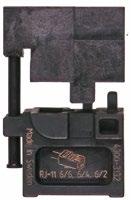
OMP45
Crimping die for Elpress MOBILE tool for crimping modular plug RJ45.
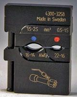
OSW0525
Crimping die for Elpress MOBILE tool for crimping through connectors with heat shrink insulation
0.5-1.5 mm2 and 1.5-2.5 mm2 AWG 15-13.
OCC1113
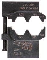
Crimping die for Elpress MOBILE tool for crimping coaxial contacts RG58, 59, 62, 71.
OMP11
Crimping die for Elpress MOBILE tool for crimping modular plug RJ11.
OCC4755
Crimping die for Elpress MOBILE tool for crimping coaxial contacts RG6, 59.

System Elpress consists of terminals and tools that are adapted and tested together for best performance. This ensures that users will feel confident when using our systems, and that a secure terminal is achieved through the proper handling of our products. Using an Elpress crimping tool when crimping an Elpress end terminal means that a terminal is obtained according to DIN 57609.
sleeves
Elpress pre-insulated and uninsulated end terminals are made of 99.95% copper and are tin plated. The end terminals have dimensions according to DIN 46228 with a few exceptions (see note in tables). The insulation boot is made of PP (polypropylene) and has a shape comparable to easy-entry, see image. Elpress end terminals are used when you need a perfect connection for the cable end
With Elpress end terminals you avoid splayed conductors and reduce the risk of cable breaks. Moreover, they create a lasting contact pressure and a large contact area.
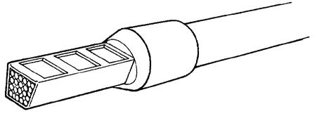
Crimped End terminal.
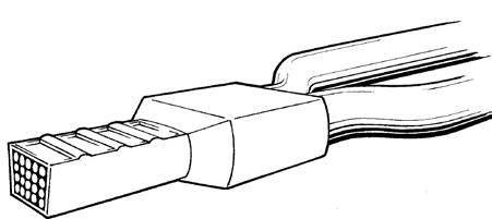
Crimped TWIN end terminal.

Easy-entry.
Colour codes for pre-insulated end terminals and TWIN-end terminals
Designation example
Cat. no. A4-12ET
A = pre-insulated
B = uninsulated
4 = area (4 mm²)
12 = Length metal sleeve
ET = end terminal
ET2 = TWIN end terminal
CSA certification
CSA, Canadian Standards Association, is a Canadian organisation that certifies products according to US standards. Elpress end sleeves of type A..ET / ETT / ETD, B. .. ET, A...ET2/ETT2/ETW2 is CSA certified according to US standard C22.2 No 158 and UL 1059 according to file No. 247206. End terminals of the type A..ET/B...ET/A...ET2 are intended for stranded Cu-conductors
26 AWG to 500 MCM, equivalent to the metric sizes 0.14 mm² to 240 mm². To be used together with Elpress crimping tool.
9
5
3
2
1/0
2/0
3/0
250
In the development of a mechanical crimping tool at Elpress, we strive for the best quality and ergonomics in the actual tool, and the best characteristics in the crimped terminal. The tools have a built-in locking system (not the hobby tools) that ensures that the entire crimping process is completed - a prerequisite for professional and quality-assured work.
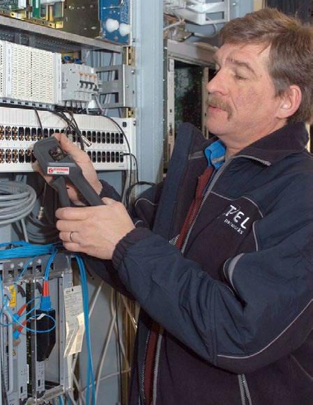
Elpress Mobile, professional tool with interchangeable dies for the installer or service technician.
With the unique Miniforce tools, a new level has been established regarding ergonomic adaptation to the user and low force requirements. This has resulted in a decrease in the grip forces by up to 45% and is the result of an advanced development process where minimisation of the risks of work-related injuries and the best ergonomics have been the deciding factors.

Miniforce type C has longer handles to facilitate two-handed operation, which is often a simple and natural way to reduce the loads. Electrical crimping tools and terminals together constitute a contact crimping system where crimping results are continuously checked against the requirements of established standards such as IEC 60352-2, SEN 245010, DIN 46429, IEC 61238-1 etc. Many of the manual tools have symmetrical crimp positions that make it possible to work from both sides - something that is important for left-handed users. The tools in the Miniforce, D and 50 series are made of very high-grade hardened steel with a black oxide finish and are laser marked.
The certificate that accompanies the tool serves several functions:
• crimping tools are often directly introduced upon procurement in a quality management system. The tool’s status at procurement shall of course be the first thing noted, to then be followed by regular checks where potential changes can be discovered and addressed.
• the certificate shows that each individual tool meets the requirements of the tool’s basic specifications.
• the certificate states what the most important characteristics are that shall be followed up.
Elpress’ service department offers the possibility of continued follow-up of the quality of the tools.
For quality assurance of our tools, we already certify the manufacture of our crimping tools, both hand tools, type Gxx, i.e. Miniforce tools, and type Dxx.

Certification of the crimping tools means that each individual tool is documented at the final assembly and inspection stage with respect to:
• handle pre-load, which is the force needed to ensure that the lock, which prevents a crimp from being interrupted, is not released too early.
• crimp die nest heights, i.e. the maximum height measurements which can be measured in each indentation with the dies pressed together.
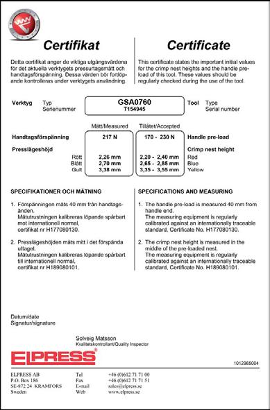
Certificate that accompanies the tool.
Get your certificate.
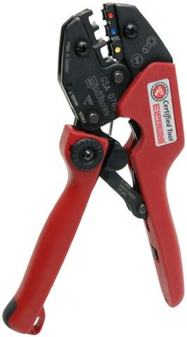
• Material: Cu 99.95%, tin plated Cu/Sn, CSA approved. • Polypropylene insulation, colour code W.


20
20
25 4 A25-16ET 10,9 29 16 18 Yes GEB1025
25 4 A25-18ET 10,9 31 18 20 Yes
25 4 A25-22ET 10,9 35 22 24 Yes
35 2 A35-16ET 12,3 30 16 18 Yes
35 2 A35-18ET 12,3 32 18 20 Yes
35 2 A35-25ET 12,3 39 25 27 Yes GEB3550 50
50 1/0 A50-20ET 15 36 20 22 Yes GEB3550 50
50 1/0 A50-25ET 15 41 25 27 Yes GEB3550 25
s = strip length
We can also offer end terminals with other colour codes and areas over 50 mm².
• Material: Cu 99.95%, tin plated Cu/Sn, CSA approved.
• Polypropylene insulation, colour code T.


s = strip length We can also offer end terminals with other colour codes and areas over 50 mm².
• Material: Cu 99.95%, tin plated Cu/Sn. CSA approved. • Polypropylene insulation, size and colour code according to DIN46228 (see table).


4 A25-18ETD 10,9 31 18 20 No GEB1025 50
25 4 A25-22ETD 10,9 35 22 24 No GEB1025 50 35 2 A35-16ETD 12,3 30 16 18 No GEB3550
2 A35-18ETD
35 2 A35-25ETD 12,3 39 25 27 No GEB3550 50
50 1/0 A50-20ETD 15 36 20 22 Yes GEB3550 50
50 1/0 A50-25ETD 15 41 25 27 No GEB3550 25 s = strip length We can also offer end terminals with other colour codes and areas over 50 mm².
• Material: Cu 99.95 %, tin plated Cu/Sn, dimension according to DIN 46228 (see table).

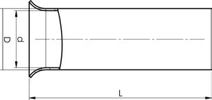
• Material: Cu 99.95%, tin plated Cu/Sn. CSA approved.
• Polypropylene insulation, colour code according to DIN 46228.

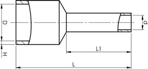
2 x 6 2x10 A6-18ET2
2x8
s = strip length Use the tool socket closest to the total area of the sleeve.
• Material: Cu 99.95%, tin plated Cu/Sn. CSA approved.
• Polypropylene insulation, colour code type T.


x 6 2x10 A6-18ETT2
2 x 10 2x8 A10-14ETT2
s = strip length Use the tool socket closest to the total area of the sleeve.
• Material: Cu 99.95%, tin plated Cu/Sn. CSA approved.
• Polypropylene insulation, colour code type W.

2 x 10 2x8 A10-14ETW2 6,5
s = strip length
Use the tool socket closest to the total area of the terminal.

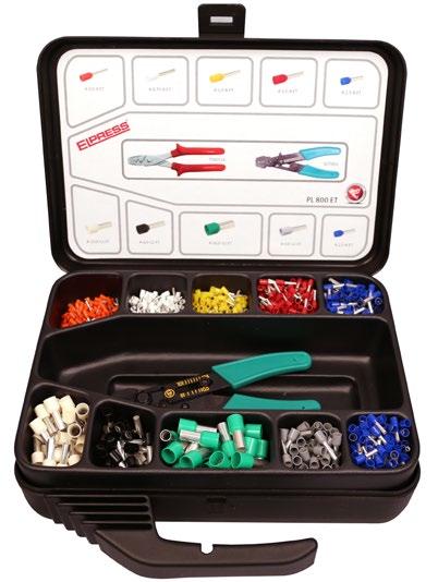
Elpress assortment boxes for professional use.
Properties:
• made of polypropylene, insert made of polystyrene
• 11 compartments
• 800 pre-insulated end sleeves 0.5-16 mm² type ET, colour code W
• stripping tool SCT001 mm² AWG
0,5-16 20-6
20-6
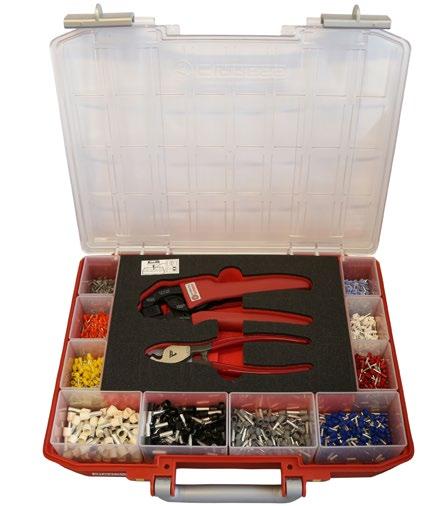
RPL5548 is a complete assortment box for electricians who like to keep things neat and tidy. A system solution for stroring high quality tools and end sleeves that are used daily.
Properties:
• practical and safe design for stacking. Comes with removable inserts, perfect for easy refilling of terminals.
• the box contains 1550 end terminals 0.14-10 mm², the PEB0110T crimping tool and the CT10 stripping tool.
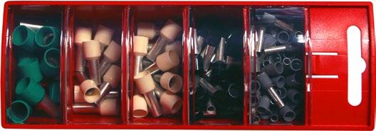
Elpress hanging assortment box.
Properties:
• made of plastic
• 5 compartments
• 100 pre-insulated end sleeves 4 - 16 mm² type ET, colour code W
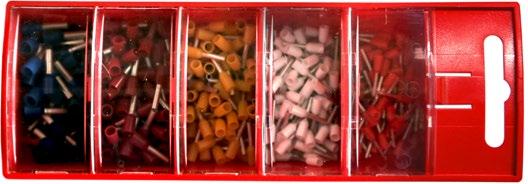
Elpress hanging assortment box.
Properties:
• made of plastic
• 5 compartments
• 400 pre-insulated end sleeves 0.5 - 2.5 mm² type ET, colour code W
• Properties:
• small and compact, ideal for confined spaces
• locking function which only releases once crimping is complete
• well balanced so the tool does not slip out of your hand
• high friction grip allows the tool to be used with a table as support
• custom hole to attach a safety line
• ergonomically designed handle made of grip friendly material
• minimum handle force required when crimping larger areas
• emergency release if the crimping process has to be interrupted
• tested with Elpress terminals
• supplied with certificate for basic quality monitoring
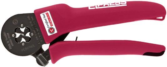
Crimp geometry
Tested and certified mechanical Miniforce hand tool for crimping end terminals 0.14-16 mm² with square crimping. mm² AWG Name Crimp geometry
26-6
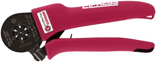
Crimp geometry
Tested and certified mechanical Miniforce hand tool for crimping end terminals 0.14-16 mm² with hexagonal crimping. mm² AWG
26-6
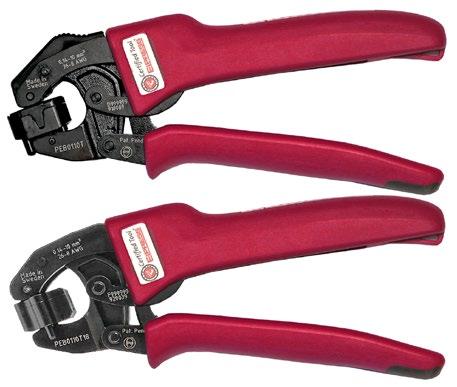
Crimp geometry
Tested and certified mechanical Miniforce hand tools for crimping end terminals 0.14-10 mm².
Special properties:
• Rotating die
• Front and side feed
mm² AWG/ MCM (Cu) Name Crimp
0,14-10 26-8 PEB0110T Trapezoid 0,385 180 65 0,14-10 26-8 PEB0110T18 Trapezoid 0,300 180 25
Properties:
• locking function which only releases once crimping is complete
• emergency release if the crimping process has to be interrupted
• symmetrical and clearly marked crimping positions
• adjustable for changes after long use
• tested with Elpress terminals
• unique mechanism that reduces maximum handle force from 450 N right down to 250 N (model C)
• ergonomic handle suitable for all users
• maximises the quality of work
• reduces the risk of occupational injuries
• light and versatile design without sacrificing on strength
• model C has extra long handles for the use of both hands
• withstands at least 80,000 crimps
• supplied with certificate for basic quality monitoring

Crimp geometries
Tested and certified mechanical Miniforce hand tool for crimping pre-insulated terminals 0.5-2.5 mm² as well as pre-insulated and uninsulated end sleeves 0.25-4 mm².
Properties
• locking function which only releases once crimping is complete
• emergency release if the crimping process has to be interrupted
• clearly marked crimping positions
• adjustable in case of changes due to long-term use
• tested with Elpress terminals
• ergonomic handle suitable for all users
• maximises the quality of work
• reduces the risk of occupational injuries
• light and versatile design without compromising durability
• model C has extra long handles for the use of both hands
• withstands at least 80,000 crimps
• supplied with certificate for basic quality monitoring

Crimp geometry
Tested and certified mechanical Miniforce hand tool for crimping pre-insulated TWIN end terminals 2 x 4-2 x 10 mm².

Crimp geometry
Tested and certified mechanical hand tool for crimping end terminals 0.5-6 mm² and insulated TWIN end terminals 2 x 0.5-2 x 4 mm².
Special properties:
• a crimp mode that automatically adjusts itself
• front-fed
• can handle crimp lengths up to 17 mm
Properties:
• locking function which only releases once crimping is complete
• emergency release if the crimping process has to be interrupted
• clearly marked crimping positions
• adjustable in case of changes due to long-term use
• tested with Elpress terminals
• ergonomic handle suitable for all users
• maximises the quality of work
• reduces the risk of occupational injuries
• light and versatile design without compromising durability
• model C has extra long handles for the use of both hands
• withstands at least 80,000 crimps
• supplied with certificate for basic quality monitoring

Crimp geometry
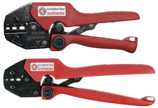
Crimp geometry
Tested and certified mechanical Miniforce hand tool for crimping end terminals 4-10 mm².
mm² AWG Name Crimp geometry Net weight (kg) Length mm Width
Tested and certified mechanical Miniforce hand tools for crimping end terminals 10-25 mm².
mm² AWG Name Crimp
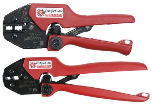
Tested and certified mechanical Miniforce hand tools for crimping end terminals 35-50 mm².
Properties:
• Li-ion battery powered (10.8 V and 2 Ah), charging time about 40 min
• very good accessibility and ergonomics
• service and installation tools
• fast crimping process 2 – 4 sec
• approximately 230 crimps/battery charge
• dies for the tool sold separately


Elpress mini tool with a sleek design with a high performance Li-Ion battery that facilitates your work with its improved battery capacity. Crimping force max. 13 kN. 1 x Li-ion battery and charger included.
Properties:
• one-handed operation for easy control of all tool functions
• durable crimping head for long service life
• optimal crimping thanks to parallel-moving dies
• easy to use due to its low weight
• high-performance 12 V Li-Ion battery – with indication of charge status
• open head, rotating
• easy and comfortable to use one handed thanks to its ergonomic 2-component housing with grip-friendly protection
• automatic return of dies when crimping is complete
mm² (Cu) AWG (Cu)
0,25-50 24-1/0

Elpress mini tools with intuitive PowerSense function combine the benefits of manual crimping tools with the benefits of battery-powered hydraulic crimping tools.
Crimping force max. 15 kN. 1 x Li-ion battery and charger included.
Properties:
• one-handed operation for easy control of all tool functions
• electronic control with locking function and monitoring for complete closure of the jaws
• safety loop used as fall protection when used outdoors
• motor protection ensures safety in case of overload
• easy and comfortable to use one handed thanks to its ergonomic 2-component housing with grip-friendly protection
• very low weight and fast crimping process for maximum efficiency
• powerful driving technology allows for easy crimps
• high-performance 12 V Li-Ion battery – with indication of charge status
• LED work lighting
• Die pair SA0760 comes with the tool
without Battery/ Charger

(Cu)
0,5-6 20-10 SA0760 Oval 0,05 Pre-insulated terminals
0,25-2,5 22-14 KB0325 Tab 0,039 Uninsulated terminals 4-10 12-8 WB4099 W 0,05 Uninsulated terminals
0,5-6 20-10 RB0560 Roll 0,05 Uninsulated terminals
0,5-6 20-10 EB0560 Trapezoid 0,057 End sleeves 4-10 12-8 EB4010 Trapezoid 0,05 End sleeves 10-25 6-4 EB1025 Trapezoid 0,05 End sleeves 35-50 2-0 EB3550 Trapezoid 0,05 End sleeves


Professional contact crimping tool with interchangeable dies for the installer or service technician.
Properties:
• reliable, safe, economic and ergonomic tools
• parallel-moving crimping movement with 10 kN crimping force, tested for 20,000 crimps
• change crimping dies quickly and easily in one operation
• the crimping dies are kept together in pairs and stored in custom holders
• wide selection of dies allows you to use one tool frame for 19 different crimping applications!
Mobile hand tool (frame only). Dies are supplementary.

Elpress Mobile + dies OAA0525 and OEB0210.

Elpress Mobile + dies OMP45 and OCC1113.
Mobile hand tool with two interchangeable dies:
• Die OAA0525 for crimping pre-insulated 0.5 - 2.5 mm² terminals.
• Die OEB0210 for crimping end sleeves 0.25 - 10 mm².
• The tool comes with associated dies in blister packaging.
Mobile hand tool with two interchangeable dies:
• OMP45 for crimping modular plug RJ45.
• OCC1113 for crimping coaxial contacts RG58, RG59, RG62 and RG71.
• The tool comes with associated dies in blister packaging.

Box for the mobile tool with room for the tool as well as 5-6 associated dies. Tools and dies are ordered separately.
All dies have the same quick and easy way of being inserted into the tool frame. The dies are kept together in pairs and supplied in a cassette that can be docked to other cassettes.


OAA0160
Crimping die for Elpress MOBILE tool for asymmetric crimping of pre-insulated terminals 0.1-4 mm2 and 4-6 mm2 AWG 11-9
OPB0140
Crimping die for Elpress MOBILE tool for crimping global power connectors, GPC connectors.
OWB4099
Crimping die for Elpress MOBILE tool for W crimping of uninsulated terminals 4-10 mm2 AWG 11-7.
OEB0210
Crimping die for Elpress MOBILE tool for crimping end sleeves 0.2510 mm2 AWG 24-7.
ORB0110
Crimping die for Elpress MOBILE tool for roll crimping uninsulated terminals 0.1-1 mm2 AWG 26-17.

OFO5432
Crimping die for Elpress MOBILE tool for crimping fibre optic contacts.

OMS4
Dies for Mobile tools for roll crimping contacts with sleeve diameter 4 mm, 2.5-6.0 mm2 AWG 13-19.


OAA0525
Crimping die for Elpress MOBILE tool for asymmetric crimping of pre-insulated terminals
0.5-2.5 mm2 AWG 20-13.
OPB6099
Crimping die for Elpress MOBILE tool for crimping global power connectors, GPC connectors.
OKB0725
Crimping die for Elpress MOBILE tool for punch crimping uninsulated terminals 0.75-2.5 mm2 AWG 18-13.
OEB1625
Crimping die for Elpress MOBILE tool for crimping end sleeves 16-25 mm2 AWG 5-3.
ORB0560
Crimping die for Elpress MOBILE tool for roll crimping uninsulated terminals 0.5-6 mm2 AWG 20-9.
OCC0908
Crimping die for Elpress MOBILE tool for crimping coaxial contacts RG174, 179.

OSW0360
Crimping die for Elpress MOBILE tool for crimping through connectors with heat shrink insulation
0.3-0.75 mm2 and 4-6 mm2 AWG 11-9.


Die for square crimping contacts 2.5-6.0 mm2 AWG 13-9.
OKB0560
Crimping die for Elpress MOBILE tool for punch crimping uninsulated terminals 0.5-6 mm2 AWG 20-9.
OEB3550
Crimping die for Elpress MOBILE tool for crimping end sleeves 35-50 mm2 AWG 2-1/0.
OMP45
Crimping die for Elpress MOBILE tool for crimping modular plug RJ45.

OSW0525
Crimping die for Elpress MOBILE tool for crimping through connectors with heat shrink insulation
0.5-1.5 mm2 and 1.5-2.5 mm2 AWG 15-13.


OCC1113
Crimping die for Elpress MOBILE tool for crimping coaxial contacts RG58, 59, 62, 71.

OMP11
Crimping die for Elpress MOBILE tool for crimping modular plug RJ11.
OCC4755
Crimping die for Elpress MOBILE tool for crimping coaxial contacts RG6, 59.


System Elpress consists of terminals and tools that are designed and tested together to give a certified crimping result. This ensures that users will feel confident when using our systems, and that a secure connection will be achieved through the proper handling of our products.
Elpress through connectors, ring, pipe, fork and pin terminals are made of high-quality copper 99.95%. The receptacles and sockets are made of brass. All terminals are then electro-tin plated for maximum corrosion protection. Terminals made of copper bands have a brazed neck which is soldered, which means that it can be crimped in any direction.
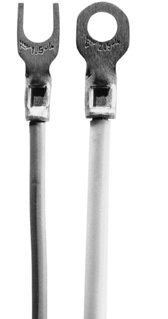
Examples of crimps using Elpress uninsulated terminals.
Elpress uninsulated terminals are marked with logotype, area and any screw diameter to facilitate work and checkability.
Cat no B1532R (G, HO, FLS etc)
B = uninsulated
15 = Area (1.5 mm²)
32 = Characteristic dimension (Hole 3.2 mm)
G = fork terminals
GS = fork terminal
H = tabs (male)
HN = tab with locking lip
HA = bullet
HO = socket
R = ring terminals
SR = pin terminal
FLS = receptacle, rolled type
FLSB = receptacle 90 rolled type
FLSH = receptacle w male rolled type
FLSN = receptacle w locking lip rolled model
FLSV = receptacle angled rolled model
Screw and washer
The following apply for bright galvanized type nuts and screws, with strength class 8.8, used for connecting terminals with Cu and Al palms:
• Always use a torque wrench to be certain the right torque is achieved. Make sure it is calibrated at regular intervals according to the supplier’s instructions.
• Use the recommended torque according to the screw manufacturer’s instructions.
• Always use a hard flat washer to reduce friction against the connection surface and the edge pressure, hardness min HB200.
• Install as illustrated.
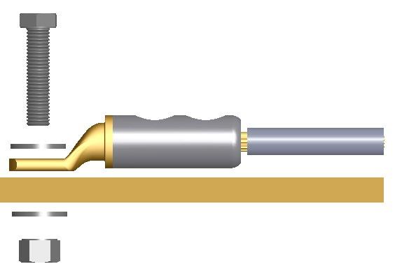
IEC - The International Electrical Commission - publishes internationally viable standards which, although not directly binding, often have great impact and are used as the basis for international deliveries. A technical report, IEC 61238-2, sets out the following recommendations regarding screw sizes for connecting terminals with Cu and Al plate provided that mounting takes place with a washer and with the correct tightening torque.
Conductor area, mm² Screw 10 M6 16-50 M8 70-95 M10 120-300 M12
400-500 M16
KR/KS, KRF/KSF, KRFS, KRT/KST UL approved in accordance with file no. E205350. UL certified products are delivered with UL marking on the label including the UL file number and/or certification code for control by an UL inspector. The certificate can be downloaded at UL Product IQ.
In the development of a mechanical crimping tool at Elpress, we strive for the best quality and ergonomics in the actual tool, and the best characteristics in the crimped terminal. The tools have a built-in locking system (not the hobby tools) that ensures that the entire crimping process is completed - a prerequisite for professional and quality-assured work.
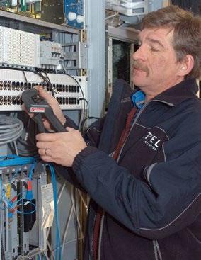
With the unique Miniforce tools, a new level has been established regarding ergonomic adaptation to the user and low force requirements. This has meant a decrease in the grip forces by up to 45% and is the result of an advanced development process where minimisation of the risks of work-related injuries and the best ergonomics have been the deciding factors.
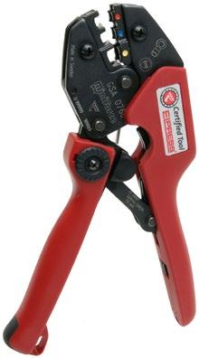
Miniforce type C has longer handles to facilitate two-handed operation, which is often a simple and natural way to reduce the loads. Electrical crimping tools and terminals together constitute a contact crimping system where crimping results are continuously checked against the requirements of established standards such as IEC 60352-2, SEN 245010, DIN 46429, IEC 61238-1 etc. Many of the manual tools have symmetrical crimp positions that make it possible to work from both sides - something that is important for left-handed users. The tools in the Miniforce, D and 50 series are made of very high-grade hardened steel with a black oxide finish and are laser marked.
The certificate that accompanies the tool serves several functions:
• crimping tools are often directly introduced upon procurement in a quality management system. The tool’s status at procurement shall of course be the first thing noted, to then be followed by regular checks where potential changes can be discovered and addressed.
• the certificate shows that each individual tool meets the requirements of the tool’s basic specifications.
• the certificate states what the most important characteristics are that shall be followed up.
Elpress’ service department offers the possibility of continued follow-up of the quality of the tools.
For quality assurance of our tools, we already certify the manufacture of our crimping tools, both hand tools, type Gxx, i.e. Miniforce tools, and type Dxx.

Certification of the crimping tools means that each individual tool is documented at the final assembly and inspection stage with respect to:
• handle pre-load, which is the force needed to ensure that the lock, which prevents a crimp from being interrupted, is not released too early.
• crimp die nest heights, i.e. the maximum height measurements which can be measured in each indentation with the dies pressed together.

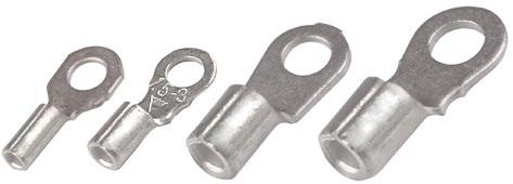
• Material: Cu 99.95%, tin plated, brazed neck.
0,25-0,75 24-20 B0832R M3 5,5 1,3 13 0,5 7 Brazed DKB0325 100
0,25-0,75 24-20 B0843R M4 7,5 1,3 16,2 0,5 7 Brazed DKB0325 100
0,25-0,75 24-20 B0853R M5 9 1,3 17 0,5 7 Brazed DKB0325 100
0,75-1,5 20-16 B1532R M3 5,5 1,8 14 0,7 7 Brazed DKB0325, DKB0760 100
0,75-1,5 20-16 B1543R M4 7 1,8 16 0,7 7 Brazed DKB0325, DKB0760 100
0,75-1,5 20-16 B1553R M5 9 1,8 18 0,7 7 Brazed DKB0325, DKB0760 100
0,75-1,5 20-16 B1565R M6 11 1,8 21,5 0,7 7 Brazed DKB0325, DKB0760 100
0,75-1,5 20-16 B1585R M8 14 1,8 23 0,7 7 Brazed DKB0325, DKB0760 100
0,75-1,5 20-16 B1510R M10 16,5 1,8 25,8 0,7 7 Brazed DKB0325, DKB0760 100
1,5-2,5 16-14 B2532R M3 6 2,3 15 0,8 8 Brazed DKB0325, DKB0760 100
1,5-2,5 16-14 B2537R M3,5 6 2,4 14 0,8 7 Brazed DKB0325, DKB0760 100
1,5-2,5 16-14 B2543R M4 7 2,4 16 0,8 8 Brazed DKB0325, DKB0760 100
1,5-2,5 16-14 B2553R M5 9 2,4 18 0,8 8 Brazed DKB0325, DKB0760 100
1,5-2,5 16-14 B2565R M6 11 2,4 21,5 0,8 8 Brazed DKB0325, DKB0760 100
1,5-2,5 16-14 B2585R M8 14 2,4 23 0,8 8 Brazed DKB0325, DKB0760 100
1,5-2,5 16-14 B2510R M10 16,5 2,4 25,75 0,7 8 Brazed DKB0325, DKB0760 100
4-6 12-10 B4643R M4 7,8 3,4 17,5 1 9 Brazed DKB0760 100
4-6 12-10 B4653R M5 9 3,4 18 1 9 Brazed DKB0760 100
4-6 12-10 B4665R M6 11 3,4 21,5 1 9 Brazed DKB0760 100
4-6 12-10 B4685R M8 14 3,4 24 1 9 Brazed DKB0760 100
4-6 12-10 B4610R M10 17 3,4 27,5 1 9 Brazed DKB0760 100
4-6 12-10 B4613R M13 19,2 3,4 32,5 1 9 Brazed DKB0760 100
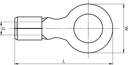
t = palm thickness, s = strip length
• Material: Cu 99.95%, tin plated Cu/Sn.
• For multi-stranded (Class 5) and get-stranded (Class 2) Cu conductors.
• UL approved (1.5 -10 mm²).
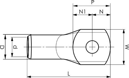
Examples of plate marking KR: 10 10 10 = mm² 10 = Plate hole for M10

0,75 (22)-18
(22)-18
1,5 (18)-16 KR1,5-3 M3
1,5 (18)-16
DKB0760 No
1,5 (18)-16 KR1,5-5 M5 7,5 1,8 4,8 4,7 9,5 18 0,85 7,5 DKB0325, DKB0760 No
2,5 (16)-14 KR2,5-3 M3 7,5 2,3 3,5 4,1 7,6 17 1,3 7 DKB0325, DKB0760 No 100
2,5 (16)-14 KR2,5-4 M4 7,5 2,3 4,2 4,1 8,3 18 1,3 7 DKB0325, DKB0760 No 100
2,5 (16)-14 KR2,5-5 M5 8,5 2,3 4,8 4,8 9,6 19 1,1 7 DKB0325, DKB0760 No 100
2,5 (16)-14 KR2,5-6 M6 8,5 2,4 5,1 5,8 10,9 19 1,1 7 DKB0325, DKB0760 No 100
4 12 KR4-3 M3 8,5 3 4,2 5,8 10 21 1,5 8,5 GWB4099, ES2258
4 12 KR4-4 M4 8,5 3 4,2 5,8 10 22 1,5 8,5 GWB4099, ES2258
4 12 KR4-5 M5 9 3 4,8 5,2 10 22 1,5 8,5 GWB4099, ES2258
4 12 KR4-6 M6 9,9 3 5 7 12 23 1,3 8,5 GWB4099, ES2258 Yes
6
palm

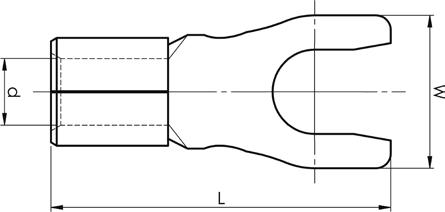
• Material: Cu 99.95%, tin plated Cu/Sn, brazed neck. mm² (Cu)
0,25-0,75 24-20 B0832G M3 5,5 1,3 13 0,5 7 Brazed DKB0325 100
0,25-0,75 24-20 B0843G M4 6,2 1,3 16,2 0,5 7 Brazed DKB0325 100
0,75-1,5 20-16 B1532G M3 5,5 1,8 14 0,7 7 Brazed DKB0325, DKB0760 100
0,75-1,5 20-16 B1537GS M3,5 5,5 1,8 16,2 0,7 7 Brazed DKB0325, DKB0760 100
0,75-1,5 20-16 B1543G M4 7 1,8 16,2 0,7 7 Brazed DKB0325, DKB0760 100
0,75-1,5 20-16 B1553G M5 9 1,8 18 0,7 7 Brazed DKB0325, DKB0760 100
1,5-2,5 16-14 B2532G M3 5,5 2,4 13 0,8 8 Brazed DKB0325, DKB0760 100
1,5-2,5 16-14 B2543G M4 7 2,4 16,2 0,8 8 Brazed DKB0325, DKB0760 100
1,5-2,5 16-14 B2553G M5 9 2,4 18 0,8 8 Brazed DKB0325, DKB0760 100
4-6 12-10 B4643G M4 7,8 3,4 17,4 1 9 Brazed DKB0760, GWB4099 100
4-6 12-10 B4653G M5 9 3,4 18 1 9 Brazed DKB0760, GWB4099 100
10 8 B9953G M5 10,5 4,5 24 1,1 11 Brazed GWB4099 100 10 8 B9965G M6 10,5 4,5 24 1,1 11 Brazed GWB4099 100
t = palm thickness, s = strip length
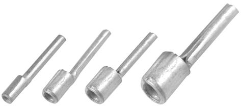
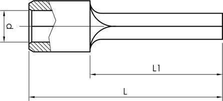
• Material: Cu 99.95%, tin plated Cu/Sn, brazed neck.
mm² (Cu) AWG Cu Name W mm d L L1 s Neck type Tool Pcs/ pack
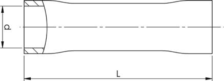
0,25-0,75 24-20 B0819SR 1,8 1,3 17,5 12 7 Brazed DKB0325 100
0,75-1,5 20-16 B1519SR 1,7 1,8 17 12 7 Brazed DKB0325, DKB0760 100
1,5-2,5 16-14 B2519SR 1,9 2,4 17 12 8 Brazed DKB0325, DKB0760 100
4-6 12-10 B4630SR 2,7 3,4 20,8 14 9 Brazed DKB0760 100 s = strip length
• Material: Cu 99.95%, tin plated Cu/Sn.
• UL approved (not KS0,75)
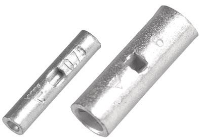
mm² (Cu) AWG Cu Name d mm D L s Tool
0,75 (22)-18

KS0,75 1,3 2,8 14 7 DKB0325, DKB0760 100
1,5 (18)-16 KS1,5 1,8 3,3 14 7 DKB0325, DKB0760
2,5 (16)-14 KS2,5 2,3 4,2 16 8 DKB0325, DKB0760
4 12 KS4 3 5 19 9 GWB4099, ES2258
6 10 KS6 4 6 19 9 GWB4099, ES2258
10 8 KS10 5 8 30 15 GWB4099, ES2258, PVL350, V600, DV1300
s = strip length
8
• Material: brass/Cu, tin plated Cu/Sn. mm² (Cu)
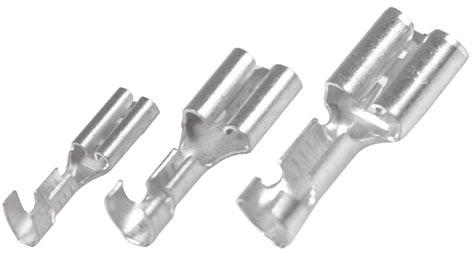
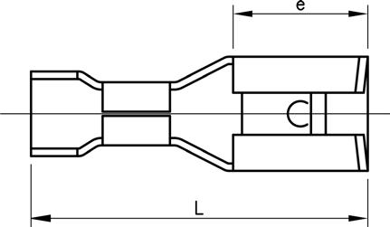
t
0,5-1 20-18 B1003FLS5 6 14 0,25 7 2,8x0,5 DRB0115 100
0,5-1 20-18 B1003FLS8 5 12,7 0,3 7 2,8x0,8 DRB0115 100
0,75-1,5 20-16 B1505FLS5-1 6,4 16 0,4 7 4,8x0,5 GRB0560 100
0,75-1,5 20-16 B1505FLS8-1 6,4 16 0,4 7 4,8x0,8 GRB0560 100
0,75-1,5 20-16 B1507FLS1 7,6 19 0,4 7 6,3x0,8 GRB0560 100
1,5-2,5 16-14 B2505FLS5 6 15,6 0,35 8 4,8x0,5 GRB0560 100
1,5-2,5 16-14 B2505FLS8 6 16 0,4 8 4,8x0,8 GRB0560 100
1,5-2,5 16-14 B2507FLS1 7,6 19 0,4 8 6,3x0,8 GRB0560 100 4-6 12-10 B4607FLS1 7,6 19 0,4 8 6,3x0,8 GRB0560 100
t = metal thickness, s = strip length
• Material: brass/Cu, tin plated Cu/Sn.
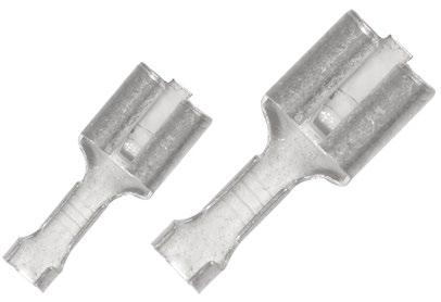
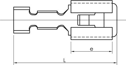
0,5-1,5 20-16 B1507FLSN 0,4 7,5 19,2 7 6,3x0,8 GRB0560 100 1,5-2,5 16-14 B2507FLSN 0,4 7,5 19 8 6,3x0,8 GRB0560 100 4-6 12-10 B4607FLSN 0,4 7,5 19 9 6,3x0,8 GRB0560 100
t = metal thickness, s = strip length
• Material: brass/Cu, tin plated Cu/Sn.
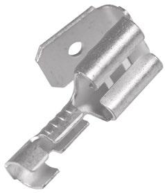
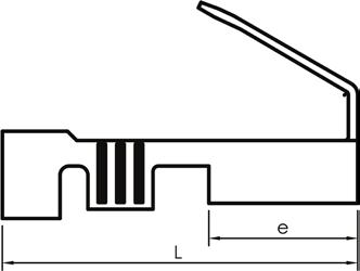
0,5-1,5
t = metal thickness, s = strip length
• Material: brass/Cu, tin plated Cu/Sn.
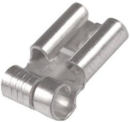
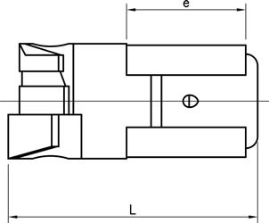
0,5-1,5
t = metal thickness, s = strip length
• Material: brass/Cu, tin plated Cu/Sn.

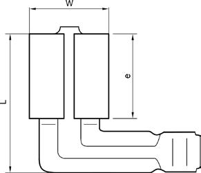
t = metal thickness, s = strip length
• Material: brass/Cu, tin plated Cu/Sn.

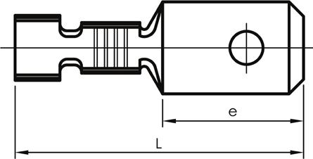
0,5-1
0,5-1,5
s = strip length
• Material: brass/Cu, tin plated Cu/Sn.
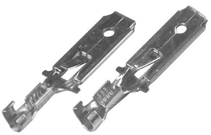

s = strip length
• Material: brass/Cu, tin plated Cu/Sn.
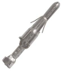
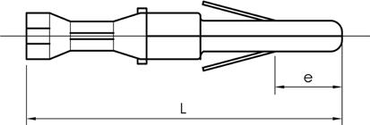
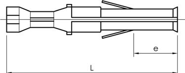
• HA = Male contact
• HO = Female contact

0,2-0,5
s = strip length
• Material: brass/Cu, tin plated Cu/Sn.
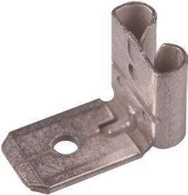
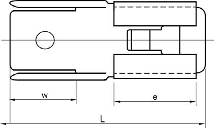
Name W mm e L Tab Pcs/pack
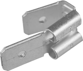
B07FLS1H 8,5 8 8,5 6,3x0,8 100
• Material: brass/Cu, tin plated Cu/Sn.
AWG
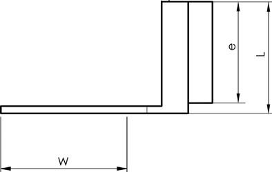
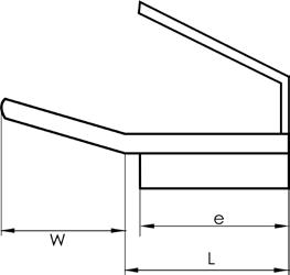
Cu Name W mm e L Tab Pcs/pack
2/0 B07FLS2H 9 7,5 18,5 6,3x0,8 100
• Material: brass/Cu, tin plated Cu/Sn.
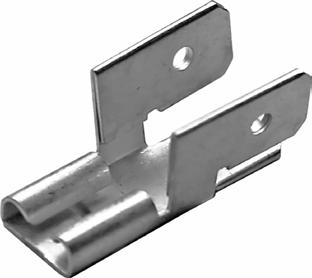
Name W mm e L Tab Pcs/pack
B07FLS3H 8 7,5 21 6,3x0,8 100
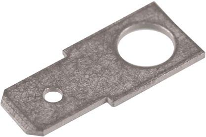
• Material: brass/Cu, tin plated Cu/Sn.
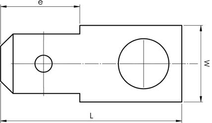
Ø = Hole diameter
• Material: brass/Cu, tin plated Cu/Sn.
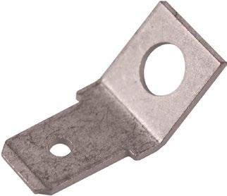
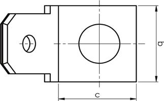
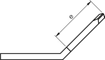
Ø = Hole diameter
• Material: brass/Cu, tin plated Cu/Sn.
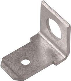
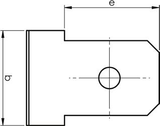
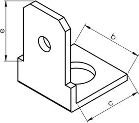
Ø = Hole diameter
• Material: brass, tin plated Cu/Sn
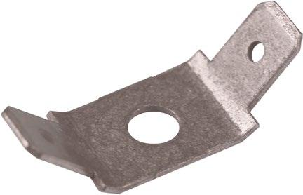
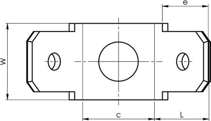
Ø = Hole diameter
• Material: brass/Cu, tin plated Cu/Sn.
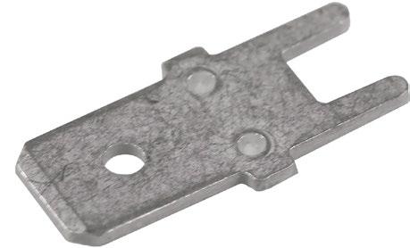
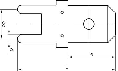
• Material: brass/Cu, tin plated Cu/Sn.

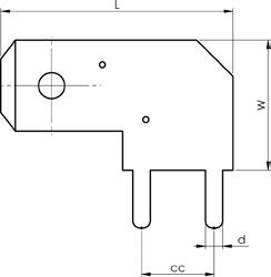
• Material: brass/Cu, tin plated Cu/Sn.
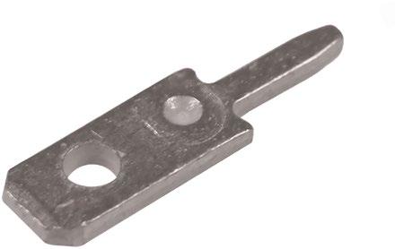
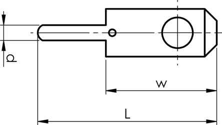
• Used in conjunction with straight tab connections.
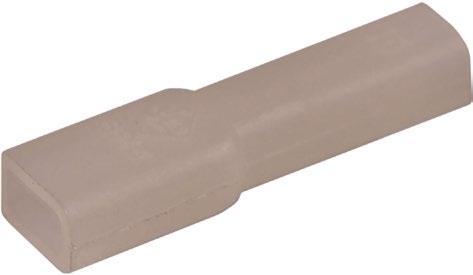
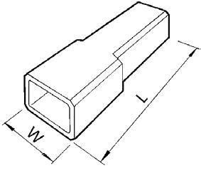
• Used in conjunction with straight tab connections.


• Used in conjunction with straight tab connections.

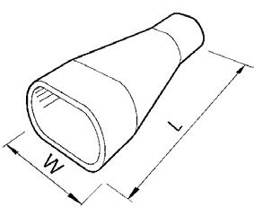
• Used in conjunction with straight tab connections.
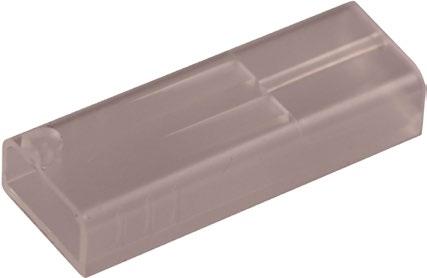
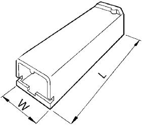
• Used in conjunction with straight tab connections.
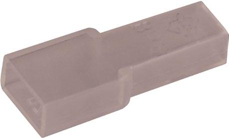
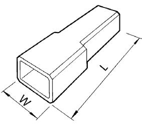
• Used with angled tab connector 90°.
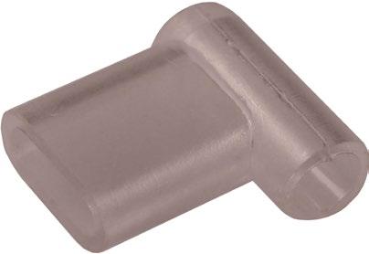
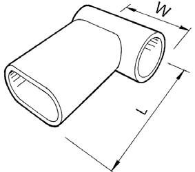
• Used with receptacles and tabs 1.5-6 mm² with locking lip.
• Material nylon transparent.
• Max voltage 250 V.
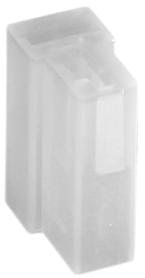
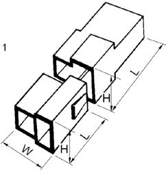
Name Pole W mm H L Pcs/pack Used with
408-2-M 2 16,4 9,7 24 100
408-4-M 4 28 15,3 24 100
408-6-M 6 29 15,2 29 100
408-8-M 8 38 15,6 34 100
408-2-F 2 20 12,7 32 100
408-4-F 4 23 17,4 33 100
408-6-F 6 31 18,7 33 50
408-8-F 8 40 18,6 33 25
B2507FLSN, B4607FLSN
B2507FLSN, B4607FLSN
B2507FLSN, B4607FLSN
B2507FLSN, B4607FLSN
B2507HN, B4607HN
B2507HN, B4607HN
B2507HN, B4607HN
B2507HN, B4607HN
• Used with sockets and bullets 0.2-1.5 mm².
• Material polyamide transparent.
• Max voltage 250 V.
• Max current 20 A.
• Temperature range -20°C to +105°C.
• Tested against breakthrough for 1 min at 1500 V AC.
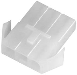
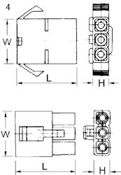
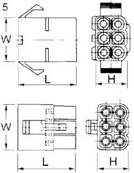
Name Pole W mm H L Pcs/pack Used with
MC02F 2 13,6 7,3 27 100
MC02M 2 13,5 7,3 27 100
MC03F 3 19,6 7,2 27 100
MC03M 3 19,6 7,1 27 100
MC04F 4 13,5 13,5 27 100
MC04M 4 13,5 13,5 27 100
MC06F 6 19,6 13,4 27 100
MC06M 6 19,6 13,4 27 100
MC09F 9 19,7 19,7 27 100
MC09M 9 19,7 19,7 27 100
MC12F 12 26 19,6 27 50
MC15F 15 32 19,6 27 50
MC15M 15 32 19,9 26 50
B0502HA, B1502HA
B0502HO, B1502HO
B0502HA, B1502HA
B0502HO, B1502HO
B0502HA, B1502HA
B0502HO, B1502HO
B0502HA, B1502HA
B0502HO, B1502HO
B0502HA, B1502HA
B0502HO, B1502HO
B0502HA, B1502HA
B0502HA, B1502HA
B0502HO, B1502HO
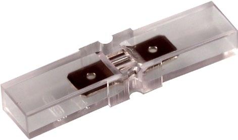
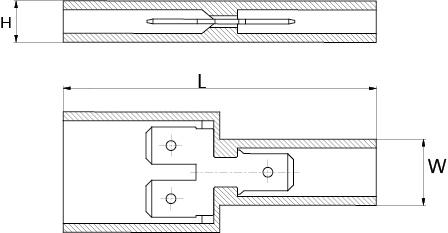
• Used in conjunction with flat pin sleeves.
• Material PVC transparent.
• Max voltage 400 V.
• Max current 18 A.
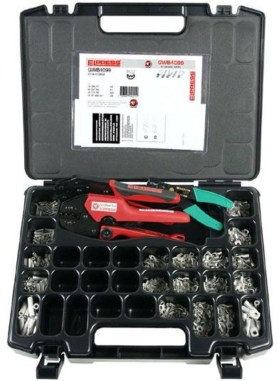
Assortment box designed for electricians in the field and for service workshops.
Properties:
• box made of LDPE/TP
• 19 compartments (+ 10 empty compartments)
• 700 uninsulated terminals and through connectors 0.75-10 mm²
• crimping tool DKB0325
• crimping tool GWB4099 Miniforce
• stripping tool SCT001
Properties:
• made of high-grade steel with semi-soft handles
• crimping positions are clearly marked
• the tools do not have a locking function
• cuts up to and including 6 mm²
• strips up to and including 6 mm²
• cuts screws M2.5-M5

Crimp geometries
Special properties:
• contact crimps pre-insulated 0.5 - 6 mm² terminals and tab crimps uninsulated 1.5 - 6 mm² terminals
• red handle

Crimp geometries
Special properties:
• contact crimps pre-insulated 0.5 - 6 mm² terminals and roll crimps uninsulated 0.5 - 2.5 mm² terminals
• yellow handle

Crimp geometry
Special properties:
• roll crimps uninsulated 0.5 - 6 mm² terminals
• green handle
Properties:
• crimp points are clearly marked
• adjustable for changes after long use
• tested with Elpress terminals according to requirements of SEN and DIN
• locking function that ensures a complete crimp
• emergency release if the crimping process has to be interrupted
• unique design that makes the tools thin and versatile
• minimal muscle strength required for complete crimp
• withstands at least 50,000 crimps
• supplied with certificate for basic quality monitoring

Crimp geometry
Crimping tool for Roller crimping terminals B1507FLSB8.
• No measuring certificate

Crimp geometry

Crimp geometry
Tested and certified mechanical hand tool for roll crimping uninsulated tab, bullet and socket terminals 0.15-1.5 mm². GRB0560 is used to crimp B1507FLS1, B1507FLSH
Tested and certified mechanical hand tool for indent crimping Cu terminals 0.25-2.5 mm².
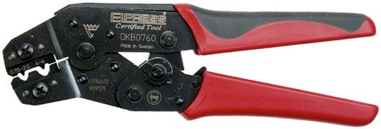
Crimp geometry
Tested and certified mechanical hand tool for indent crimping Cu terminals 0.75-6 mm².
• Properties:
• locking function which only releases once crimping is complete
• emergency release if the crimping process has to be interrupted
• clearly marked crimping positions
• adjustable for changes after long use
• tested with Elpress terminals
• unique mechanism that reduces maximum handle force from 450 N right down to 250 N (model C)
• ergonomic handle suitable for all users
• maximises the quality of work
• reduces the risk of occupational injuries
• light and versatile design without sacrificing on strength
• model C has extra long handles for the use of two hands
• withstands at least 80,000 crimps supplied with certificate for basic quality monitoring
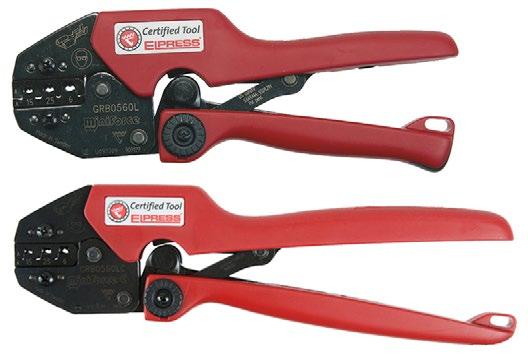
Tested and certified mechanical Miniforce hand tool for roll crimping uninsulated terminals 0.5-6 mm². The tool is type L equipped with three interchangeable locators for different types of terminals (see table).
Type LC has long handles.
Special properties:
• delivered in practical plastic box
• locator that holds the terminal in the correct position when crimping and gives you an ”extra hand” that facilitates work in, for example, confined spaces
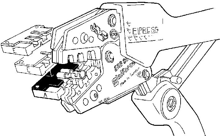
B2507FLS1 B2507FLSN
B4607FLSN B4607FLS1

Crimp geometry

Crimp geometry

Crimp geometry
Tested and certified mechanical Miniforce hand tool for roll crimping uninsulated terminals 0.5-6 mm².
Tested and certified mechanical Miniforce hand tool for W crimping uninsulated ring, fork and pin terminals as well as tube terminals and through connectors type KR and KS 4-10 mm².
Tested and certified mechanical Miniforce hand tool for W crimping un-insulated ring, fork and pin terminals as well as tube terminals and through connectors type KR/KRT and KS/KST 4-10 mm².
Properties:
• Li-ion battery powered (10.8 V and 2 Ah), charging time about 40 min
• very good accessibility and ergonomics
• service and installation tools
• fast crimping process 2 – 4 sec
• approximately 230 crimps/battery charge
• dies for the tool sold separately


Elpress mini tool with a sleek design with a high performance Li-Ion battery that facilitates your work with its improved battery capacity. Crimping force max. 13 kN. 1 x Li-ion battery and charger included.
Properties:
• one-handed operation for easy control of all tool functions
• durable crimping head for long service life
• optimal crimping thanks to parallel-moving dies
• easy to use due to its low weight
• high-performance 12 V Li-Ion battery – with indication of charge status
• open head, rotating
• easy and comfortable to use one handed thanks to its ergonomic 2-component housing with grip-friendly protection
• automatic return of dies when crimping is complete
mm² (Cu) AWG (Cu)
0,25-50 24-1/0
0,25-50 24-1/0
0,25-50 24-1/0
85 60 Charger: 230VAC
85 60 Charger: 115VAC
85 60 without Battery/Charger

Elpress mini tools with intuitive PowerSense function combine the benefits of manual crimping tools with the benefits of battery-powered hydraulic crimping tools.
Crimping force max. 15 kN. 1 x Li-ion battery and charger included.
Properties:
• one-handed operation for easy control of all tool functions
• electronic control with locking function and monitoring for complete closure of the jaws
• safety loop used as fall protection when used outdoors
• motor protection ensures safety in case of overload
• easy and comfortable to use one handed thanks to its ergonomic 2-component housing with grip-friendly protection
• very low weight and fast crimping process for maximum efficiency
• powerful driving technology allows for easy crimps
• high-performance 12 V Li-Ion battery – with indication of charge status
• LED work lighting
• Die pair SA0760 comes with the tool
without Battery/Charger

(Cu)
0,5-6 20-10 SA0760 Oval 0,05 Pre-insulated terminals
0,25-2,5 22-14 KB0325 Tab 0,039 Uninsulated terminals 4-10 12-8 WB4099 W 0,05 Uninsulated terminals
0,5-6 20-10 RB0560 Roll 0,05 Uninsulated terminals
0,5-6 20-10 EB0560 Trapezoid 0,057 End sleeves 4-10 12-8 EB4010 Trapezoid 0,05 End sleeves 10-25 6-4 EB1025 Trapezoid 0,05 End sleeves 35-50 2-0 EB3550 Trapezoid 0,05 End sleeves


Professional contact crimping tool with interchangeable dies for the installer or service technician.
Properties:
• reliable, safe, economic and ergonomic tools
• parallel-moving crimping movement with 10 kN crimping force, tested for 20,000 crimps
• change crimping dies quickly and easily in one operation
• the crimping dies are kept together in pairs and stored in custom holders
• wide selection of dies allows you to use one tool frame for 19 different crimping applications!
Mobile hand tool (frame only). Dies are supplementary.

Elpress Mobile + dies OAA0525 and OEB0210.

Elpress Mobile + dies OMP45 and OCC1113.
Mobile hand tool with two interchangeable dies:
• Die OAA0525 for crimping pre-insulated 0.5 - 2.5 mm² terminals.
• Die OEB0210 for crimping end sleeves 0.25 - 10 mm².
• The tool comes with associated dies in blister packaging.
Mobile hand tool with two interchangeable dies:
• OMP45 for crimping modular plug RJ45.
• OCC1113 for crimping coaxial contacts RG58, RG59, RG62 and RG71.
• The tool comes with associated dies in blister packaging.


Mobile hand tool with three interchangeable dies and cable stripper LOKE for stripping solar panel cable with extra thick insulation:
• OMS4, roll crimping of contacts with sleeve Ø 4 mm, 2.5 - 6.0 mm².
• OMS3, square crimping of contacts with sleeve Ø 3 mm, 2.5 - 6.0 mm².
• OMSL, square crimping of contacts, 2.5 - 6.0 mm².

Box for the mobile tool with room for the tool as well as 5-6 associated dies. Tools and dies are ordered separately.
Name
All dies have the same quick and easy way of being inserted into the tool frame. The dies are kept together in pairs and supplied in a cassette that can be docked to other cassettes.


OAA0160
Crimping die for Elpress MOBILE tool for asymmetric crimping of pre-insulated terminals 0.1-4 mm2 and 4-6 mm2 AWG 11-9
OPB0140
Crimping die for Elpress MOBILE tool for crimping global power connectors, GPC connectors.
OWB4099
Crimping die for Elpress MOBILE tool for W crimping of uninsulated terminals 4-10 mm2 AWG 11-7.
OEB0210
Crimping die for Elpress MOBILE tool for crimping end sleeves 0.2510 mm2 AWG 24-7.
ORB0110
Crimping die for Elpress MOBILE tool for roll crimping uninsulated terminals 0.1-1 mm2 AWG 26-17.

OFO5432
Crimping die for Elpress MOBILE tool for crimping fibre optic contacts.

OMS4
Dies for Mobile tools for roll crimping contacts with sleeve diameter 4 mm, 2.5-6.0 mm2 AWG 13-19.


OAA0525
Crimping die for Elpress MOBILE tool for asymmetric crimping of pre-insulated terminals
0.5-2.5 mm2 AWG 20-13.
OPB6099
Crimping die for Elpress MOBILE tool for crimping global power connectors, GPC connectors.
OKB0725
Crimping die for Elpress MOBILE tool for punch crimping uninsulated terminals 0.75-2.5 mm2 AWG 18-13.
OEB1625
Crimping die for Elpress MOBILE tool for crimping end sleeves 16-25 mm2 AWG 5-3.
ORB0560
Crimping die for Elpress MOBILE tool for roll crimping uninsulated terminals 0.5-6 mm2 AWG 20-9.
OCC0908
Crimping die for Elpress MOBILE tool for crimping coaxial contacts RG174, 179.

OSW0360
Crimping die for Elpress MOBILE tool for crimping through connectors with heat shrink insulation
0.3-0.75 mm2 and 4-6 mm2 AWG 11-9.


Die for square crimping contacts 2.5-6.0 mm2 AWG 13-9.
OKB0560
Crimping die for Elpress MOBILE tool for punch crimping uninsulated terminals 0.5-6 mm2 AWG 20-9.
OEB3550
Crimping die for Elpress MOBILE tool for crimping end sleeves 35-50 mm2 AWG 2-1/0.
OMP45
Crimping die for Elpress MOBILE tool for crimping modular plug RJ45.

OSW0525
Crimping die for Elpress MOBILE tool for crimping through connectors with heat shrink insulation
0.5-1.5 mm2 and 1.5-2.5 mm2 AWG 15-13.


OCC1113
Crimping die for Elpress MOBILE tool for crimping coaxial contacts RG58, 59, 62, 71.

OMP11
Crimping die for Elpress MOBILE tool for crimping modular plug RJ11.
OCC4755
Crimping die for Elpress MOBILE tool for crimping coaxial contacts RG6, 59.


System Elpress consists of terminals and tools that are designed and tested together to give a certified crimping result. This ensures that users will feel confident when using our systems, and that a secure connection is achieved through the proper handling of our products. By using Elpress Cu-connection elements together with one of Elpress crimp systems one obtains a connection that has been tested according to the requirements of IEC 61238:1.

Elpress copper connectors are made of pure copper 99.95%. We manufacture tube terminals type KR/KRF/KRD/KRT, through connectors type KS/KSF/KSD/ KST for stranded conductors, IEC 60228 class 2, and multi-stranded conductors IEC 60228 class 5 such as C-sleeves primarily pre-splicing of Cu-lines and many customised products. For flexible and stranded Cu conductors, terminals of type KR/KRF and through connectors of type KS/KSF are used. Terminals type KRD/KRT and through connectors type KSD/KST are normally used for stranded Cu conductors from and including 500 mm². Terminals of type KR/KRF/KRD/ KRT are used mainly in termination to bus bars and apparatus of copper, while through connectors, of type KS/KSF/KSD/ KST, are used mainly in the splicing of copper conductors in cable assemblies. They can also be used for straight splicing of earth conductors. With a branching sleeve, type C, one splices and branches earth conductors, lightning conductor installations and the like.
KR/KS, KRF/KSF, KRFS, KRFN, KRT/KST
UL approved in accordance with file no. E205350.
Elpress KR/KS, KRF/KSF and KRT/KST terminals meet DNV’s rules for classification of ships and Det Norske Veritas’ Offshore Standards. The terminals are approved for installations on ships and mobile “offshore” units.
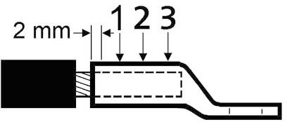
Normally one crimp is required up to and including 150 mm² and two or three crimps for larger areas. Note, however, that another number of crimps may be needed in some cases, see tables for tool dies. If possible, crimps should be placed next to each other with a couple of mm spacing between each one. Overlap is sometimes inevitable.

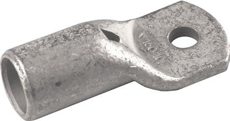
Marking of Cu terminals
Elpress marking system for copper terminals shows logotype, cable area and type number for hexagonal die. This system allows checks that the correct tools have been used when contact crimping because the die number automatically becomes embossed during the contact crimping.
Marking tube terminals
25 (on neck)
Type No. for hexagonal die (Elpress logo) 150 12 F (on the palm)
150 = Cu conductor in mm²
12 = Hole size
F = KRF
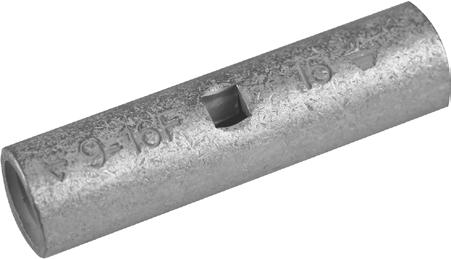
Marking through connectors
Elpress Logo
Type No. for hexagonal die
16 F (possible screened conductor area and earthing sign)
16 = Cu conductor in mm²
F = KSF
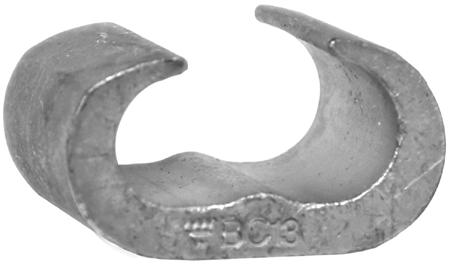
Marking C-sleeves (example C70-95)
Area marking (side 1)
25-120 / 140-190
min - max (mm² per conductor) / min - max (total mm² in the sleeve)
Elpress logo, Die number (side 2)
BCx, "x" corresponds to die number
Screw size Hole diameter (Ø mm)
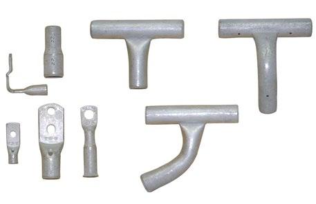
Customised products
Screw and washer
The following apply for bright galvanized type nuts and screws, with strength class 8.8, used for connecting terminals with Cu and Al palms:
• Always use a torque wrench to be certain the right torque is achieved. Make sure it is calibrated at regular intervals according to the supplier’s instructions.
• Use the recommended torque according to the screw manufacturer’s instructions.
• Always use a hard plain washer to reduce friction against the connection surface and the edge pressure, hardness min HB200.
• Install as illustrated.

Customised products are an important part of our work. Solving problems for the customer and at the same time manufacturing the products with profitability is a special challenge. This way, we also increase our knowledge of the customers’ needs. The above terminals include different models of T-connectors where you can connect three conductors of the same size using only one terminal. These are used, for example, in transformer manufacturing. Other connections in transformer manufacturing are lead-in pins and special terminals for switches. In conclusion, all terminals are designed to easily ensure a high-quality connection even in advanced applications.
• Material: Cu 99.95%, tin plated Cu/Sn.
• For multi-stranded (class 5) and stranded (class 2) Cu conductors.
• UL approved (1.5 -10 mm²).
Examples of palm marking KR: 10 10
10 = mm² 10 = Palm hole for M10

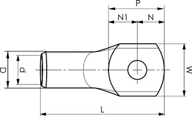
(22)-18
(22)-18
1,5 (18)-16 KR1,5-3 M3
(18)-16
DKB0325, DKB0760 No
1,5 (18)-16 KR1,5-5 M5 7,5 1,8 4,8 4,7 9,5 18 0,85 7,5 DKB0325, DKB0760 No
2,5 (16)-14 KR2,5-3 M3 7,5 2,3 3,5 4,1 7,6 17 1,3 7 DKB0325, DKB0760 No
2,5 (16)-14 KR2,5-4 M4 7,5 2,3 4,2 4,1 8,3 18 1,3 7 DKB0325, DKB0760 No
2,5 (16)-14 KR2,5-5 M5 8,5 2,3 4,8 4,8 9,6 19 1,1 7 DKB0325, DKB0760 No
2,5 (16)-14 KR2,5-6 M6 8,5 2,4 5,1 5,8 10,9 19 1,1 7 DKB0325, DKB0760 No
4 12 KR4-3 M3 8,5 3 4,2 5,8 10 21 1,5 8,5 GWB4099, ES2258
4 12 KR4-4 M4 8,5 3 4,2 5,8 10 22 1,5 8,5 GWB4099, ES2258 Yes
4 12 KR4-5 M5 9 3 4,8 5,2 10 22 1,5 8,5 GWB4099, ES2258
4 12 KR4-6 M6 9,9 3 5 7 12 23 1,3 8,5
6
6
t = palm thickness, s = strip length
• Material: Cu 99.95%, tin plated Cu/Sn.
• Inspection hole
• For stranded (class 2) and multi-stranded (class 5) Cu conductors
• For multi-stranded Cu conductors Elpress recommends the DUAL system.
• UL approved (KRF16-500 mm²), DNV approved (16-400 mm²).
Example of marking KRF: 17 (neck) Elpress logotype 70 10F (palm)
17 = Die No. 70 = mm² 10 = palm hole for M10 F = type KRF for stranded and flexible conductors.
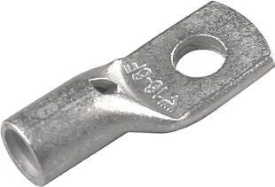
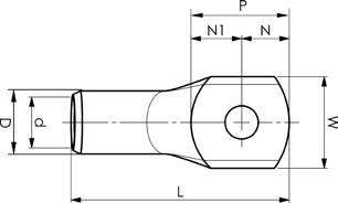
• Material: Cu 99.95%, tin plated Cu/Sn.
• Inspection hole
• For stranded (class 2) and multi-stranded (class 5) Cu conductors.
• For multi-stranded Cu conductors Elpress recommends the DUAL system.
• UL approved (16-400 mm²), DNV approved (see note).
Example of marking KRF: 17 (neck) Elpress logotype 70 10F (palm)
17 = Die No. 70 = mm² 10 = palm hole for M10 F = type KRF for stranded and flexible conductors.

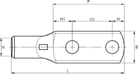
16 6
25 4
M8x2 16 8 9,5 10,5 60 40 81 2,8 13 PVL350, V600, DV1300, V250 100 11
25 4 KRF25-10X2-40 M10x2 18 8 11 19 70 40 93 2,5 14 PVL350, V600, DV1300, V250 100 11
25 4 KRF25-14X2-40 M14x2 22 8 15 17 72 40 94 1,8 13 DV1300, V250, V600, PVL350 100 11
35 2 KRF35-10X2-24-26 M10x2 18 9 11 16 52 25 78 3,9 16 PVL350, V600, DV1300, DV250 100 13
35 2 KRF35-10X2-40 M10x2 20 9 11 19 70 40 95 3,5 16 PVL350, V600, DV1300, DV250 100 13
50 1/0 KRF50-10X2-24-26 M10x2 21 11 11 16 52 25 82 3,4 19 PVL350, V600, DV1300, DV250 100 14,5
50 1/0 KRF50-10X2-40 M10x2 21 11 11 19 70 40 100 3,3 19 PVL350, V600, DV1300, DV250 100 14,5
70 2/0 KRF70-10X2-24-26 M10x2 25 13 11 17 53 25 86 3,9 22 PVL350, V600, DV1300, DV250 50 17
70 2/0 KRF70-12X2-40 M12x2 25 13 12 18 70 40 103 3,9 22 PVL350, V600, DV1300, DV250 25 17 DNV approved
95 4/0 KRF95-10X2-24-26 M10x2 29 15 11 19 55 25 93 4,9 25 V600, DV1300, DV250 25 20
95 4/0 KRF95-12X2-40
120 250 KRF120-12X2-40 M12x2 32 17 12 19 71 40 113 4,9 27 V600, DV1300, DV250 25 22 DNV approved
150 300 KRF150-10X2-24-26
t = palm thickness, s = strip length
• Material: Cu 99.95%, tin plated Cu/Sn.
• Inspection hole
• For stranded (class 2) and multi-stranded (class 5) Cu conductors.
• For multi-stranded Cu conductors Elpress recommends the DUAL system.
•Easy to install via cable gland, allows for pre-installation.
•The width of the palm is less than or as wide as the neck.
• UL-approved (95-300 mm² ), DNV approved.
Example of marking KRFS: 17 (neck) Elpress logotype 70 10F (palm) 17 = Die no. 70 = mm² 10 = palm hole for M10 F = type KRF for stranded and flexible conductors.
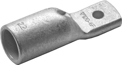
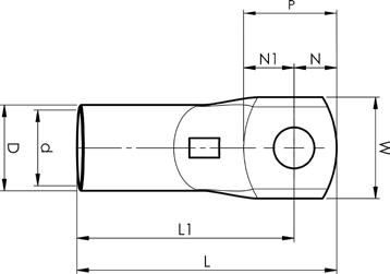
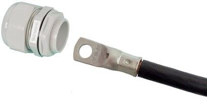
length Easy to install via cable gland.
• Material: Cu 99.95%, tin plated Cu/Sn.
• Inspection hole
• For stranded (class 2) and multi-stranded (class 5) Cu conductors.
• For multi-stranded Cu conductors Elpress recommends the DUAL system.
• UL approved (35-150 mm²). DNV approved (16-150 mm²).
Example of marking KRF: 17 (neck) Elpress logotype 70 10F (palm)
17 = Die No. 70 = mm² 10 = palm hole for M10 F = type KRF for stranded and flexible conductors.
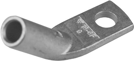
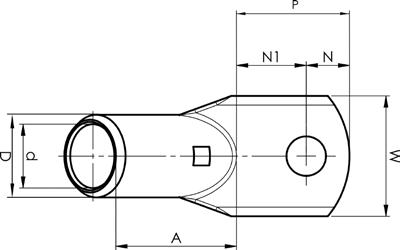
t = palm thickness, s = strip length
• Material: Cu 99.95%, tin plated Cu/Sn.
• Inspection hole
• For stranded (class 2) and multi-stranded (class 5) Cu conductors.
• For multi-stranded Cu conductors Elpress recommends the DUAL system.
• UL approved (35-150 mm²). DNV approved (16-150 mm²).
Example of marking KRF: 17 (neck) Elpress logotype 70 10F (palm)
17 = Die No. 70 = mm² 10 = palm hole for M10 F = type KRF for stranded and flexible conductors.
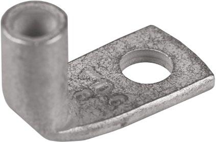
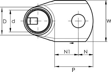
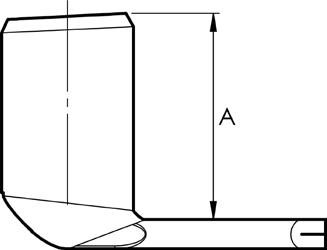
35 2
185
185
• Material: Cu 99.95%, tin plated Cu/Sn.
• Inspection hole.
• For stranded (class 2) Cu conductors.
• UL approved (10-500 mm²), DNV approved (10-400 mm²).
Example of marking KRT: 16 (neck) Elpress logotype 70 10 (palm) 16 = Die No. 70 = mm² 10 = palm hole for M10
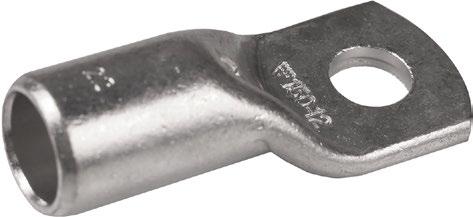
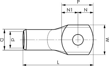
• Material: Cu 99.95%, tin plated Cu/Sn.
• Inspection hole.
• For stranded (class 2) Cu conductors.
Example of marking KRD:
14 (neck) Elpress logotype 70 10 (palm)
14 = Die No. 70 = mm²
10 = palm hole for M10
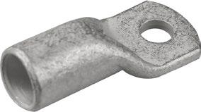
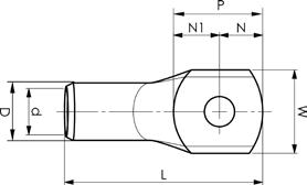
• Material: Cu 99.95%, tin plated Cu/Sn.
• Inspection hole.
• For stranded (class 2) Cu conductors.
Example of marking KRD:
14 (neck) Elpress logotype 70 10 (palm)
14 = Die No. 70 = mm²
10 = palm hole for M10


t = palm thickness, s = strip length
• Din tube terminals for Cu conductors.
• Material: Cu 99.95%, tin plated Cu/Sn.
• Dimensions according to DIN 46235, the number of crimps is indicated on the neck of the terminal.
• For crimping DIN 46235 terminals, use dies according to DIN 48083.
Example of plate marking: 95 1095 = mm² 10 = palm hole for M10
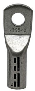
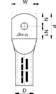
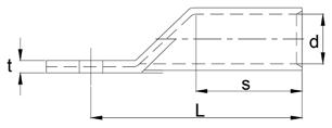
M12
35 2 KRDIN35-10 M10 19 8,2 12,5 13,5 13,5 27 55,5 3,7 20 V600, V1300 50 12DIN
35 2
50 1/0 KRDIN50-6 M6 20 10 14,5 11,5 11,5 23
50 1/0 KRDIN50-8 M8 20 10 14,5 11,5 11,5 23 63,5 4,3 28 V600, V1300 50 14DIN
50 1/0 KRDIN50-10 M10 22 10 14,5 13,5 13,5 27 65,5 3,9 28 V600, V1300 50 14DIN
50 1/0 KRDIN50-12 M12 24 10 14,5 14,5 14,5 29
50 1/0 KRDIN50-16 M16 28 10 14,5 17,5 17,5 35 69,5 3,1 28 V600, V1300 50 14DIN
70 2/0 KRDIN70-6 M6 24 11,5 16,5 11,5 11,5 23 66,5 4,5 28 V600, V1300 25 16DIN
70 2/0 KRDIN70-8 M8
2/0
M8
120
120 250 KRDIN120-20
150 300 KRDIN150-12 M12 34
150 300 KRDIN150-16 M16 34 17 23,5 17,5
150 300 KRDIN150-20 M20
185 350 KRDIN185-10 M10 37 19
185 350 KRDIN185-12 M12 37 19 25,5 13,5 13,5
185 350 KRDIN185-16 M16 37 19
185 350 KRDIN185-20 M20 40 19 25,5
V1300 20 22DIN
35 V600, V1300 20 22DIN
V600, V1300 20 22DIN
V1300, V250 10 25DIN
95,5 6 40 V1300, V250 10 25DIN
V1300, V250 10 25DIN
t = palm thickness, s = strip length
• Material: Cu 99.9% tin plated Cu/Sn.
• Dimensions acc. to DIN 46234.
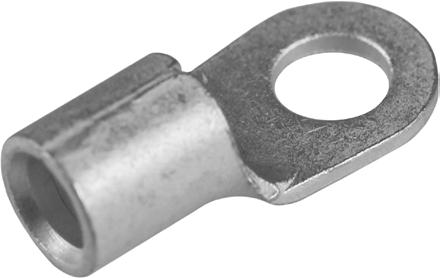
10 8
10 8
10 8
10 8
10 8
16 6
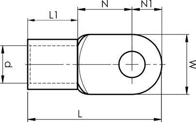
B10-5R M5 10 4,5 8 5 16
GWB4010, V600, V1300, V250 100 7
B10-6R M6 11 4,5 9 5,5 17 GWB4010, V600, V1300, V250 100 7
B10-8R M8 14 4,5 12 7 27
GWB4010, V600, V1300, V250 100 7
B10-10R M10 18 4,5 13 9 21 GWB4010, V600, V1300, V250 100 7
B10-12R M12 22 4,5 15 11 23 GWB4010, V600, V1300, V250 100 7
B16-5R M5 11 5,8 10 5,5 26 V600, V1300, V250
16 6 B16-6R M6 11 5,8 10 5,5 26 V600, V1300, V250
16 6 B16-8R M8 14 5,8 12 7 29 V600, V1300, V250
16 6
16 6
B16-10R M10 18 5,8 14 9 33 V600, V1300, V250
B16-12R M12 22 5,8 16 11 37 V600, V1300, V250
16 6 B16-16R M16 30 5,8 24 15 49 V600, V1300, V250
25 4 B25-6R M6 12 7,5 14 6 31 V600, V1300, V250
25 4 B25-8R M8 16 7,5 14 8 33 V600, V1300, V250
25 4 B25-10R M10 18 7,5 15 9 35 V600, V1300, V250
25 4 B25-12R M12 22 7,5 20 11 42 V600, V1300, V250
25 4 B25-16R M16 28 7,5 24 14 49 V600, V1300, V250
35 2 B35-6R M6 15 9 14 7,5 34 V600, V1300, V250
35 2 B35-8R M8 16 9 14 8 34 V600, V1300, V250
35 2 B35-10R M10 18 9 15 9 36 V600, V1300, V250
35 2 B35-12R M12 22 9 19 11 42 V600, V1300, V250
35 2 B35-16R M16 28 9 24 14 50 V600, V1300, V250
50 1/0 B50-6R M6 18 11 18 9 43 V600, V1300, V250
50 1/0 B50-8R M8 18 11 18 9 43 V600, V1300, V250
50 1/0 B50-10R M10 18 11 18 9 43 V600, V1300, V250
50 1/0 B50-12R M12 22 11 20 11 47 V600, V1300, V250
50 1/0 B50-16R M16 28 11 24 14 54 V600, V1300, V250
70 2/0 B70-8R M8 22 13 20 11 49 V600, V1300, V250
70 2/0 B70-10R M10 22 13 20 11 49 V600, V1300, V250
70 2/0 B70-12R M12 22 13 20 11 49 V600, V1300, V250
70 2/0 B70-16R M16 28 13 24 14 56 V600, V1300, V250
95 4/0 B95-10R M10 24 15 22 12 54 V600, V1300, V250
95 4/0 B95-12R M12 24 15 22 12 54 V600, V1300, V250
8
8
8
8
8
8
10
10
10
10
10
12
12
12
12
12
14,5
14,5
14,5
14,5
14,5
17
17
17
17
20
20
95 4/0 B95-16R M16 28 15 24 14 58 V600, V1300, V250 100 20
120 250 B120-10R M10 24 16,5 22 12 56 V600, V1300, V250
120 250 B120-12R M12 24 16,5 22 12 56 V600, V1300, V250
120 250 B120-16R M16 28 16,5 26 14 62 V600, V1300, V250
150 300 B150-12R M12 30 19 26 15 65 V600, V1300, V250
150 300 B150-16R M16 30 19 26 15 65 V600, V1300, V250
185 350 B185-12R M12 36 21 22 18 68 V1300, V250
185 350 B185-16R M16 36 21 22 18 68 V1300, V250
* Contact Elpress
*
*
*
• Material: Cu 99.95%, tin plated Cu/Sn.
• Inspection hole and int. cable stop.
• For stranded (class 2) and multi-stranded (class 5) Cu conductors.
• For multi-stranded Cu conductors Elpress recommends the DUAL system.
• UL approved (1-500 mm²). DNV approved (16-400 mm²).
Examples of marking: 20 95F (Elpress logotype is included on the marking.)
20 = Die No. 95 = mm² F = type KSF for stranded and flexible conductors 111 = screen mm²
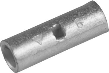

0,75 (22)-18 KS0,75 1,3 2,8 14 7 DKB0325, DKB0760
1,5 (18)-16 KS1,5 1,8 3,3 14 7 DKB0325, DKB0760
2,5 (16)-14 KS2,5 2,3 4,2 16 8 DKB0325, DKB0760
4 12 KS4 3 5 19 9 GWB4099, ES2258
6 10 KS6 4 6 19 9 GWB4099, ES2258
10 8 KS10 5 8 30 15 GWB4099, ES2258, PVL350, V600, DV1300
16 6 KSF16 15 6 9 35 17 ES2258, PVL350, V600, DV1300
25 4 KSF25 21-29 8 11 35 17 ES2258, PVL350, V600, DV1300
1/0
70 2/0 KSF70 72-88 13 17 45 22 V600, DV1300, DV250
95 4/0 KSF95 111 15 20 45 25 V600, DV1300, DV250
8
9
20 120 250 KSF120 17 22 55 27 V600, DV1300, DV250
150 300 KSF150 19 25 65 32 V600, DV1300, DV250
s = strip length
• Material: Cu 99.95%, tin plated Cu/Sn.
• For stranded (class 2) and multi-stranded (class 5) Cu conductors.
• For multi-stranded Cu conductors Elpress recommends the DUAL system.
• With partition to prevent oil leakage.
• UL approved (1-500 mm²). DNV approved (16-400 mm²).
Examples of marking: 20 95F (Elpress logotype is included on the marking.)
20 = Die No. 95 = mm² F = type KSF for stranded and flexible conductors 111 = screen mm²
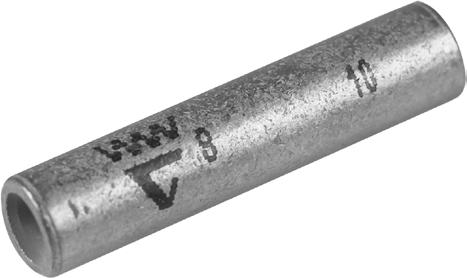
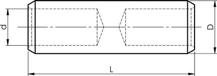
10 8 KS10M 5 8 36 18 ES2258, PVL350, V600, DV1300 100 8
16 6 KSF16M 15 6 9 37 18 ES2258, PVL350, V600, DV1300 100 9
25 4 KSF25M 21-29 8 11 38 18 ES2258, PVL350, V600, DV1300 100 11
35 2 KSF35M 41 9 13 41 19 PVL350, V600, DV1300, DV250 100 13
50 1/0 KSF50M 57 11 14,5 48 22 PVL350, V600, DV1300, DV250 50 14,5
70 2/0 KSF70M 72-88 13 17 49 22 PVL350, V600, DV1300, DV250 50 17
95 3/0 KSF95M 111 15 20 56 25 V600, DV1300, DV250 50 20
120 250 KSF120M 17 22 63 28 V600, DV1300, DV250
150 300 KSF150M 19 25 64 28 V600, DV1300, DV250
185 350 KSF185M 21 27 74 32 DV1300, DV250
240 500 KSF240AM 22,5 29 76 32 DV1300, DV250
300 600 KSF300AM 24,5 31,5 88 37 DV1300, DV250 1 32
400 750 KSF400AM 30 38 105 45 DV1300, DV250
500 1000 KSF500M 33 42 135 54 DV250, V1470
s = strip length
• Material: Cu 99.95%, tin plated Cu/Sn.
• For stranded (class 2) Cu conductors.
• Cable inspection hole and cable stop.
• UL approved (1-500 mm²). DNV approved (16-400 mm²).
Examples of marking: 16 70 (Elpress logotype is included on the marking.)
16 = Die No. 70 = mm²
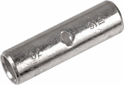
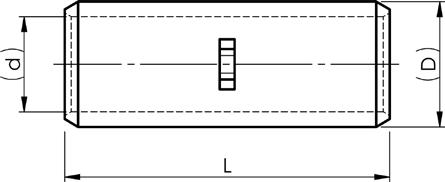
10 8 KST10 4,5 7 30 15 ES2258, PVL350, V600, V1300
16 6 KST16 5,5 8,5 35 17 EL2258, PVL350, V600, V1300
8,5 25 4 KST25 7 10 40 20 EL2258, PVL350, V600, V1300
10 35 2 KST35 8,5 12 45 22 PVL350, V600, V1300, V250
50 1/0 KST50 10 14 50 25 PVL350, V600, V1300, V250
70 2/0 KST70 12 16 55 27 PVL350, V600, V1300, V250
16 95 4/0 KST95 13,5 18 60 30 V600, V1300, V250
120 250 KST120 15 19 60 30 V600, V1300, V250
19 150 300 KST150 17 22 65 32 V600, V1300, V250
600 KST300 24 30 90 45 V1300, V250
750 KST400 26 32 90 45 V1300, V250
500 1000 KST500 31 40 135 68 V250, V1470
s = strip length
• Material: Cu 99.95%, tin plated Cu/Sn.
• For stranded (class 2) Cu conductors.
• Cable inspection hole and cable stop.
• UL approved (1-500 mm²). DNV approved (16-400 mm²).
Examples of marking: 16 95 (Elpress logotype is included on the marking.)
16 = Die No. 95 = mm²
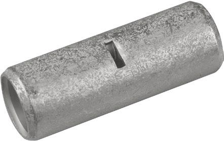

• Material: Cu 99.95%, tin plated Cu/Sn.
• For multi-stranded (class 5) and stranded (class 2) Cu conductors.
• For multi-stranded Cu conductors Elpress recommends the Dual system.
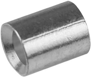
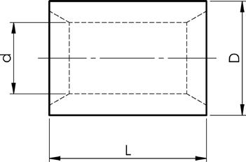
0,5-1,5 20-16 KS1,5P 1,6 3,2 7 3 DKB0325 100
1,5-3,0 16-12 KS2,5P 2,3 3,9 7 3 DKB0325 100
3,25-6,75 12-9 KS6P 3,6 5,6 7 3 DKB0760 100
s = strip length
• Material: Cu 99.95%, tin plated Cu/Sn.
• For stranded (class 2) and multi-stranded (class 5) Cu conductors.
• For multi-stranded Cu conductors Elpress recommends the Dual system.

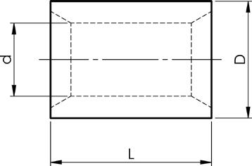
7-12 8 KS10P 5 8 11 PVL350, V600, DV1300, DV250
8 12,5-18,5 6 KS16P 6 9 12 PVL350, V600, DV1300, DV250
9 20-31 4 KS25P 8 11 14 PVL350, V600, DV1300, DV250 200 11 31-41 2 KS35P 9 13 16 PVL350, V600, DV1300, DV250
13 45-56 1/0 KS50P 11 14,5 18 PVL350, V600, DV1300, DV250
60-85 2/0 KS70P 13 17 18 PVL350, V600, DV1300, DV250
86-111 4/0 KS95P 15 20 20 V600, DV1300, DV250
111-130 250 KS120P 17 22 26 V600, DV1300, DV250
• Material: Cu 99.95%, tin plated Cu/Sn.
• For single-wire conductors (acc. to IEC 60228 class 1).
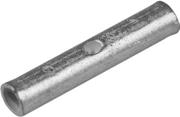

6 10 CUT6 3 5 27 12 ES2258, T2258 100 10 8 CUT10 4 6 27 12 ES2258, T2258 100 16 6 CUT16 5 8 35 15,5 ES2258, T2258 100
s = strip length
The Elpress logo is included on the marking.
• Material: Cu 99.95%, tin plated Cu/Sn.
• Dimensions according to DIN 46230.

d L
10 8
16 6
25 4
35 2
50 1/0
70 2/0
95 3/0
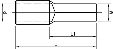
B10SR 4,3 4,5 22 12 V600, V1300, V250 100 7
B16SR 5,5 5,8 26 13 V600, V1300, V250 100 8
B25SR 6,8 7 34 15 V600, V1300, V250 100 10
B35SR 8 8,7 41 20 V600, V1300, V250 100 12
B50SR 9,5 9,8 45 20 V600, V1300, V250 50 14,5
B70SR 11 11,5 55 23 V600, V1300, V250 50 17
B95SR 12,3 13,8 55 23 V600, V1300, V250 50 20
• Material: Cu 99.95%, tin plated Cu/Sn
• For cable 10 mm² Cu Solid (Excel) and 16 mm² stranded (Fxcel), installed with strain relief.
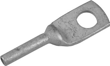

• Material: Cu 99.95%, tin plated Cu/Sn
• For cable 10 mm² Cu Solid (Excel) and 16 mm² stranded (Fxcel), installed with strain relief.
• With internal cable stop
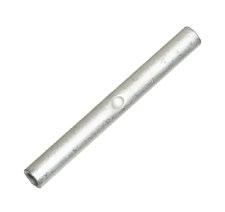

10 8 KSX10 4,5 7 65 30 V600, V1300 3 7
16 6 KSX16 5,5 8,5 65 30 V600, V1300 3 8,5 s = strip length
The Elpress logo is included on the marking.Two plus two crimps are carried out with the V600, V611, PVX611 or T2600 system, crimp die TB7-20.
• Material: Cu 99.95%. Tin plated sleeves (except C95-120, C150-185, C240-300 and C23 which are not tin plated).
• For splicing and branching earth lines and other types of equipotential bonding applications. In some cases, 2 or 3 crimps are required.
• Unique patented solution based on previously patented solution for the C25-50 branching sleeve (formerly known as C89).
• Possible to front feed all branches.
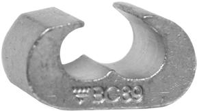
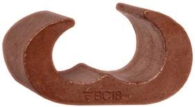

C6-10 6/6-16, 10/6-16 6-10/6-10, 16/10
C16-25 16/16-25, 25/(2*2,5)-25 16-25/16-25, 25/(2*2,5)-10
C25-50 25-50/25-50, 16-50/35-50
C50-70 50/50, 70/25-70, 95/25-50 50/50, 70/25-70, 95/25-50
C70-95 70/70, 95/50-95, 120/25-70 70/70, 95/50-70, 120/25-50
C95-120 95/95, 120/70-120, 150/25-70, 185/25-50 95/95, 120/70-120, 150/25-70, 185/25-50
C150-185 150/95-150, 185/70-185, 240/25-185, 300/25-120 150/95-150, 185/70-185, 240/25-185, 300/25-120
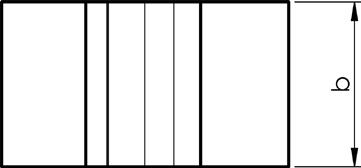
Elpress logotype is included on the marking. The other side of the C sleeve is marked with the size of the Cu wire that fits.
* Side feed only
** For Front feed with uncompressed conductors, use C240-300
Reference list, see next page
C15-13
C16-9
C18-9
C18-8
C21-18*
C16-13
C18
C18-16
C18-15
C18-13
C18-11
C18/23-8
C21-15
C21-16
C21-13
C21-11
C21-9
C21-8
C240-300 C21
C23-21
C23-18 C23-16
2 crimps B25C18 1 crimp B40C18
2 crimps B25C21
1 crimp B40C21
2 crimps B25C21 1 crimp B40C21
* Non-compacted main conductor and branch, use C240-300
** Side feed, front feed in C95/120
*** 50 mm²/50 mm² side feed, front feed in C50-70 1) Die holder required: V2506, V2508 2) Die holder required: V1316, V1318 3) Die holder required: V1330
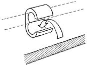

System Elpress consists of terminals and tools that are designed and tested together to give a certified crimping result. This ensures that users will feel confident when using our systems, and that a secure connection is achieved through the proper handling of our products.
Elpress terminals for Al cable are made of solid and pure aluminium 99.7%. We manufacture Al terminals type AK and AS, but also customised terminals or terminals larger than 1200 mm².

Terminal type AK is used with Al conductors for connection to busbars and apparatus sockets.

Through connectors type AS are used when connecting aluminium-conductors.
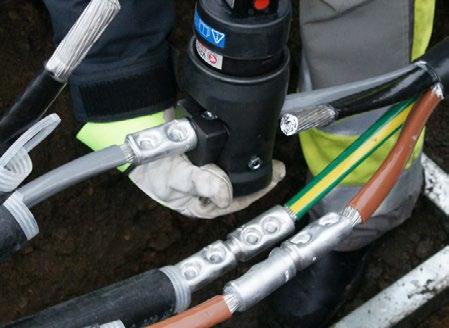
Indent crimping of Elpress through connector using crimp head V250.
Elpress bimetallic terminals (AlCu) are manufactured from solid material which is friction welded together, joining Aluminium with Copper. This is done when aluminium is rotated towards copper under pressure and it is the method that provides the best connection between Al and Cu.

Terminals of type AKK are used at the end of an Al conductor for connection to a Cu bus bar.

Through connectors of type AKS are used to connect Al conductors to Cu conductors.
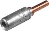
Pin sockets type AKP are manufactured for connection of Al conductors to apparatus intended for copper pin connections.
The Elpress system is suitable for both stranded conductors, acc. to IEC 60228 class 2, and solid conductors, acc. to IEC60228 class 1. However, it should be noted that there is an area difference between stranded and solid Al conductors (see tables). When using sectoral Al-cable, a pre-rounding is normally required, which is done with a round crimping tool. When contact crimping Al terminals, two crimps should always be made. Note the crimp sequence.
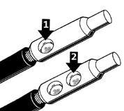
Customised products are an important part of our work. Solving problems for the customer and at the same time manufacturing the products with profitability is a special challenge. This way, we also increase our knowledge of the customers’ needs. The above terminals include different models of T-connectors where you can connect three conductors of the same size using only one terminal.
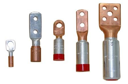
Upon request for variants in hole arrangement, the size of the connection flag and the like, we make variants of cable clips.
Elpress system for marking Al and AlCu terminals states the conductor area (for small and solid conductors) and reference to rounded and contact crimp tools within the Elpress range. A tool reference for hexagonal crimping copper is given on the bimetallic through connectors.
TERMINALS:
Explanatory marking Al and AlCu terminals
Barrel marking i.e. ALU300-R21-P36 (Elpress logotype) T2
ALU300 = Al conductor in mm²
R21 = size no. for punch and matrix for pre-rounding
P36 = size no. for punch and matrix for crimping
Palm marking: (Elpress logo) 16 = Screw dimension
THROUGH CONNECTORS:
Explanatory marking Al and AlCu terminals
For example: Cu240 - 30 (Elpress logotype)
Cu240 = Cu conductor in mm²
30 = Size no. for hexagonal die
For example: ALU300-R21-P36 (Elpress logotype) T2
ALU300 = Al conductor in mm²
R21 = size no. for punch and matrix for pre-rounding
P36 = size no. for punch and matrix for crimping
Clearance for holes in terminal palm Screw
• Used for connecting Al conductors to Al busbar.
• Two crimps are needed - For crimp sequence, see image.
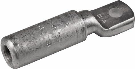
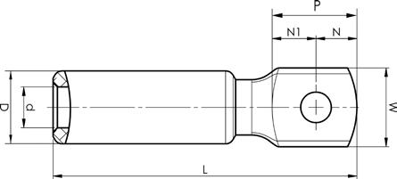
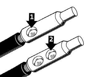
• Used primarily for connecting two Al conductors with the same area.
• Two plus two crimps are needed - For crimp sequence, see image.
• Partition in the middle to prevent fluid flow.
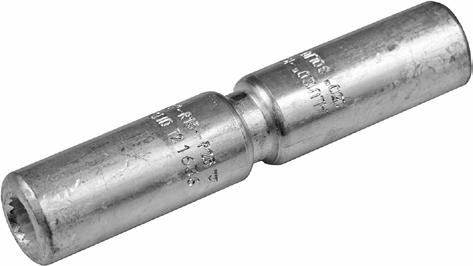


For other combinations, please contact Elpress. s = strip length
• Used for connecting Al conductors of different areas.
• Two plus two crimps are needed - crimp sequence see picture.
• With partition.
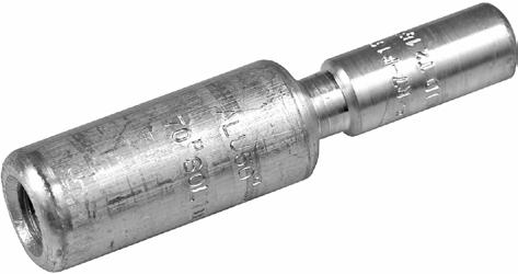


s, s1 = insulation stripping length
• Used primarily for connecting two Al conductors with the same area
• For the indent crimping of Al-terminals, two crimps are always required, see image.
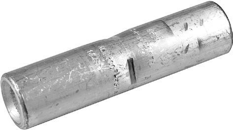


s = strip length
• Used for connection of Al conductors for apparatus outlets and busbars of Cu.
• Two crimps are needed - For crimp sequence, see image.
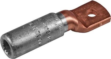
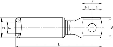

• Used for connection of Al conductors for apparatus outlets and busbars of Cu, etc.
• For stranded wire Al conductor.
• Two crimps are needed, see image.
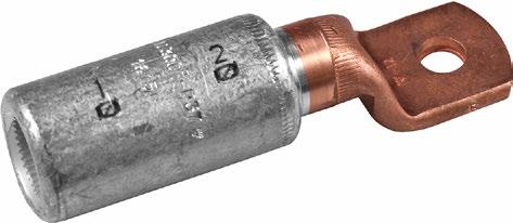
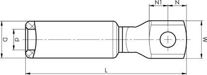

300
t = palm thickness, s = strip length
• Used for connection of Al conductors to apparatus with copper connectors.
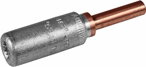

• Two crimps are needed - For crimp sequence, see image. Crimp

• Used for connecting stranded Al conductors to solid Cu conductors 10 mm²/8 AWG (e.g. Excel, Excelett).
• Two crimps are needed for both Al (crimp sequence see image) and Cu.


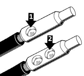
s = strip length (Al), s1 =
• Used for connecting Al conductors and Cu conductors
• Stranded/solid Al conductors, stranded/flexible Cu conductors. For multi-stranded Cu conductors, contact crimping using the DUAL system is recommended.
• Two crimps are needed for Al (see image).
• When crimping the Al part, use matrix P2537M and punch P2537D, no matrix holder is needed.
• When crimping the Cu part, place the dies between the marking on the sleeve and the edge of the Cu part.
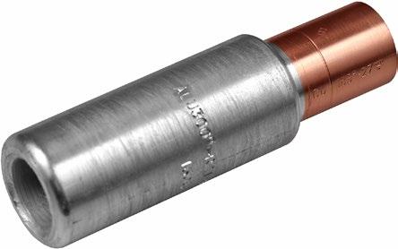


300
300
400
400
If class 5 Cu conductors are used, use the corresponding DUAL tool for (D)V1300 or (D)V250., s = strip length (Al), s1 = strip length (Cu)
s
• Connector from Al conductor to Cu conductor.
• Stranded/solid Al conductors, stranded/multi-stranded Cu conductors.
• For multi-stranded Cu conductors, contact crimping using the DUAL system is recommended.
• Two crimps are required for Al (see image) normally one for Cu.
• When hexagonally crimping the Cu part, the dies are placed between the marking groove and the outer edge.


System Elpress consists of terminals and tools that are designed and tested together to give a certified crimping result. This ensures that users will feel confident when using our systems, and that a secure connection will be achieved through the proper handling of our products.
Elpress hydraulic crimp systems crimp from 10 to 1200 mm². The systems consist of pumps and crimp heads that can be freely combined or with complete hand-held tools, where these devices are integrated. Wide range of accessories available for crimping, pre-rounding, cutting etc. Together with the matching terminals, the complete system is formed. Both pumps and hand-held tools have, with a few exceptions, quick feed function that means crimping can begin after a few pump strokes. The systems have a built-in ratchet lock that ensures that an initial crimp is completed and thus produces results with the best characteristics. Pumps that can be connected to the different crimp heads provide the option of comfortable work in difficult situations and with maximum flexibility.
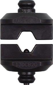
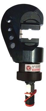
The V1300 system is used for crimping Cu-terminals 10-400 mm². An openhead C version is also available for better access in confined spaces.
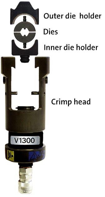
The V1300 system is used for the indent crimping of Al connections and pre-rounding of Al conductors 16-240 mm². Round crimping is carried out on sector-shaped Al conductors.
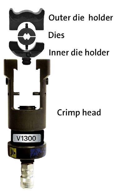
The V250 system is used for crimping Cu-terminals 10-800 mm².
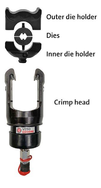
The V250 system is used for indent crimping Al-terminals and pre-rounding Al conductors 16-630 mm². Round crimping is carried out on sector-shaped Al conductors.
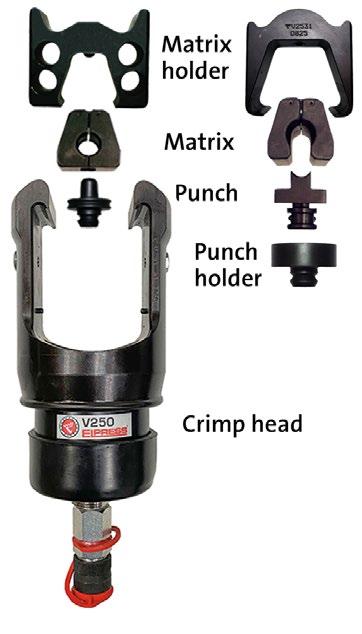
Properties:
• certified tool for connection according to norms
• ergonomic handles facilitate installation
• scissor movement for access in confined spaces
• ratchet function that does not release until the crimp is complete
• hexagonal crimping with clearly marked crimping positions

Crimp geometry
Tested and certified mechanical hand-held tool for crimping Cu-terminals, type CUT 6-16 mm² and KR/KS 4-10 mm².

Crimp geometry
Tested and certified mechanical hand-held tool for crimping Cu-terminals, type KRF/KSF 16-25 mm².

Crimp geometries
Tested and certified mechanical hand-held tool for crimping Cu-terminals, type CUT 6-16 mm² and KR/KRF/KS/KSF 4-16 mm².

Crimp geometry
Tested and certified mechanical hand-held tool for crimping Cu-terminals, type KRT/KST 10-25 mm².

Crimp geometry
Tested and certified mechanical hand-held tool for crimping Cu-terminals 10-16 mm² and Al 16-25 mm².
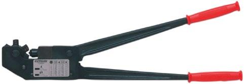
Crimp geometry
Mechanical hand-held tool for crimping Cu-terminals.
Properties:
• equipped with ratchet function
• crimp wheels, rolled steel, which provide high strength
• crimp force up to approx. 35 kN
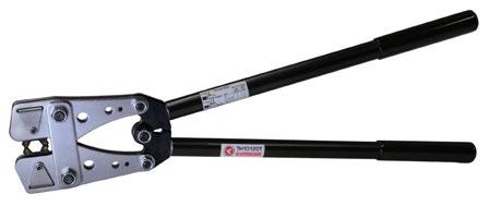
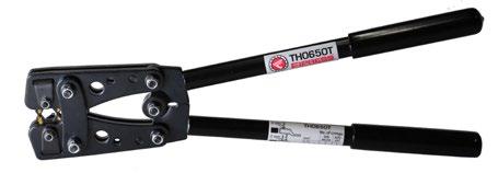
Crimp geometry
Mechanical hand-held tool for crimping Cu-terminals, type KR/KRT and KS/KST, 6-120mm².
Properties:
• rotating crimping wheel
• no full closure mechanism
• crimp force up to approx. 35 kN


Crimp geometries
Battery-powered tool for crimping tube terminals and through connectors of type KR/KS, KRF/KSF, KRT/KST 10-70 mm² and KRD/KSD up to 95 mm² with special ”MB” dies.
Properties:
• opening head for easy die changes and good accessibility
• high-performance 10.8 V Li-Ion battery with indication of charge status
• very good accessibility and ergonomics
• opening, rotatable ”flip top” head for easy die changes and slim crimp head for good accessibility
• rapid crimp sequence 3-4 seconds
• approx. 100-180 crimps/battery charges (depending on temp, frequency etc.)
• 2-component housing with grip-friendly protection. One-handed operation for easy control of all tool functions
• lightweight, and rapid crimping sequence for maximum efficiency
• automatic return of the dies when crimping is complete
(Cu)
4-95 PVL350 Hexagonal, Oval 1,6
4-95 PVL350-US Punch, Hexagonal, Oval 1,6
116 75 Charger: 230VAC
116 75 Charger: 115VAC
4-95 PVL350-WOBC Punch, Hexagonal, Oval 1,1 360 116 75 without Battery/ Charger
Supplied in pairs. For hexagonal crimping of Cu 4-70 mm², class 2, 5 and 6 conductors acc. IEC 60228, CUT sleeves 6-16 mm² crimped with MB4016. C-sleeves 6-25 mm² are crimped with MBC5 and MBC6.
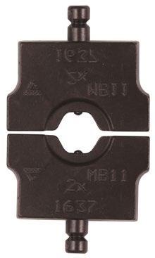
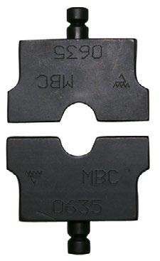
Die pair MB11 for PVL350. Die pair MBC5 for PVL350
Supplied in pairs. For hexagonal crimping of Cu (class 2) 10-70 mm².

Die pair MB11 for PVL350.
mm² KRT/KST Name Number of crimps Net weight (kg)
10 MB7 1 0,088
16 MB8,5 1 0,087
25 MB10 2 0,084
35 MB12 2 0,083
50 MB14 3 0,080 70 MB16 3 0,075
Supplied in pairs. For hexagonal crimping of Cu (class 2) 10-95 mm².

Die pair MB11 for PVL350.
mm²
KRD/KSD Name Number of crimps Net weight (kg)
10 / 16 MB8 1 0,086
25 MB9 2 0,085
35 MB11 2 0,083
50 MB12 2 0,083
70 MB14 3 0,080 95 MB17 3 0,075

Crimp geometries
Tested and certified crimp head for crimping Cu-terminals, type KR/KS 10 mm², KRF/KSF 16-150 mm², KRD/KSD 16-185 mm², KRT/KST 10-240 mm², Al-terminals 16-25 mm² (-35 solid), C-sleeves 6/6-50/50 mm², DIN 46235 10-95 mm². Used in combination with foot pump P4000 or the electrically powered pump PS710 (battery powered version of PS710E is also available).
Properties:
• working pressure 63 MPa (630 bar)
• crimp force 55 kN
• robust fabric bag with room for 10 dies included
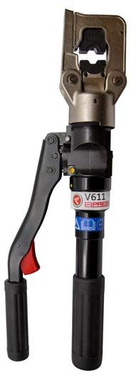
Crimp geometries
Tested and certified hand-held tool for crimping Cu-terminals, type KR/KS 10 mm², KRF/ KSF 16-150 mm², KRD/KSD 16-185 mm², KRT/KST 10-240 mm², Al-terminals 16-25 mm² (-35 solid), C-sleeves 6/6-50/50 mm², DIN 46235 10-95 mm².
Properties:
• fast-feed to crimp engagement provides short crimp times
• crimp force 55 kN
• delivered in sturdy textile bag
(Cu) mm² (Stranded Al) mm² (Solid Al)
16-25 16-35


Crimp geometries
Tested and certified battery-powered crimp tool for crimping Cu-terminals, type KR/KS 10 mm², KRF/KSF 16-150 mm², KRD/KSD 16-185 mm², KRT/KST 10-240 mm², Al-terminals 16-25 mm² (-35 solid), C sleeves 6/6-50/50 mm², DIN 46235 10-95 mm². PVX611DB has an extra battery.
Properties:
• protects against dirt and dust through the closed chassis
• ergonomic design ensures optimum balance in the user’s hand
• swivel opening crimp fork
• crimp force control using pressure monitoring
• one handed operation for easy work
• LED lighting for easier work
• fast-forward feeding for more efficient crimping
• display with information about the tool and service intervals
• tested together with Elpress TB dies and KB22/KB25
• crimp monitoring via display when the correct pressure/complete crimping is not achieved (warning light LED and signal)
10-150 16-25 16-35 PVX611DB
Delivered with 2 batteries 10-150 16-25 16-35 PVX611-US Punch, Oval, Hexagonal
Hexagonal
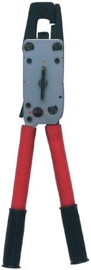
Crimp geometries
Without Battery/ Charger
Mechanical hand-held tool for crimping Cu-terminals, type KR/KS 10 mm², KRF/KSF 16-95 mm², KRD/KSD 16-120 mm², KRT/KST 10-120 mm², Al-terminals 16-25 mm² (-35 solid), and C-sleeves 6/6-50/50 mm², DIN 46235 10-95 mm².
Properties:
• opening for easy die changes and for quick removal after jointing
• crimp force approx. 57 kN
• advanced force ratio for lowest handle force
• easy to work with in confined spaces
• only four die pairs are required to crimp 10-95 mm² Cu
• quick feed function
• delivered in a metal box mm² (Cu) mm² (Solid Al) Name Crimp geometries
10-95 35 T2600 Punch, Hexagonal, Oval 1,9 445 185 52
10-120 35 T2600B Punch, Hexagonal, Oval 4,12 445 185 52 10-120 35 T2600C Punch, Hexagonal, Oval 4,12 445 185 52
For Cu-terminals, hexagonal crimping. Supplied in pairs. The TB dies below are intended for Cu-terminals, type KRF/KSF, together with Cu conductor according to IEC 60228 (class 2, 5 and 6).
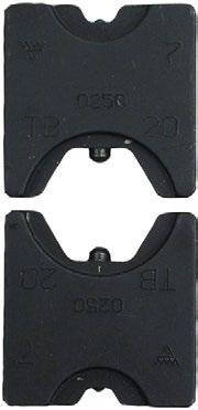
Die pair TB7-20 for V600, V611, PVX611 and T2600.
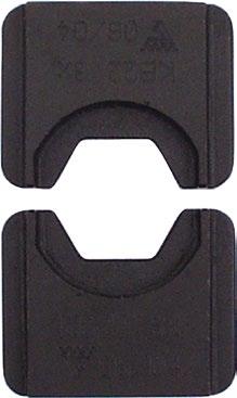
Die pair KB22 for V600, V611 and PVX611.
mm² KR/KS, KRF/KSF Name Number of crimps Net weight (kg)
10 / 70 TB8-17 1, 2 0,138
16 / 35 TB9-13 1 0,149
25 / 50 TB11-14,5 1 0,149
10 / 95 TB7-20 1, 2 0,135
120 KB22 3 0,150
150 KB25 3 0,147
KBxx is not allowed to be used with T2600
For Cu-terminals, hexagonal crimping. Supplied in pairs. The TB dies below are intended for Cu-terminals, type KRD/KSD, together with Cu conductor according to IEC 60228 (class 2).

Die pair TB7-20 for V600, V611, PVX611 and T2600.

Die pair KB22 for V600, V611 and PVX611.
mm² KRD/KSD Name Number of crimps Net weight (kg)
16 / 70 TB8-14 1 0,149
25 / 50 TB9-12 1 0,150
35 / 95 TB11-16 1, 2 0,142
150 KB22 3 0,150
185 KB25 3 0,147
KBxx is not allowed to be used with T2600
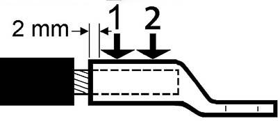
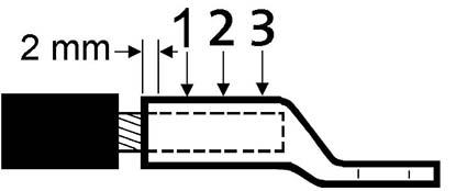
Crimp sequence for two crimps. Crimp sequence for three crimps.


Crimp sequence for two crimps. Crimp sequence for three crimps.
For Cu-terminals, hexagonal crimping. Supplied in pairs. The TB dies below are intended for Cu-terminals, type KRT/KST, together with Cu conductor according to IEC 60228 (class 2).

Die pair TB7-20 for V600, V611, PVX611 and T2600.

Die pair KB22 for V600, V611 and PVX611.


Crimp sequence for two crimps. Crimp sequence for three crimps.
/
/
/
/
KBxx is not allowed to be used with T2600
For joints on overhead lines AlMgSi (Super B) and Al59, hexagonal crimping. Supplied in pairs.
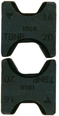
Die pair TBNP 16-20.
mm²
Overhead line Name Number of crimps Net weight (kg) Note
31 - 99 TBNP16-20 2x5, 2x10 0,135 Used for AlMgSl and FeAl, LFS31, LFS62 and LFS99
For Cu branching with C-sleeves, oval crimping. Supplied in pairs.
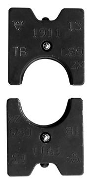
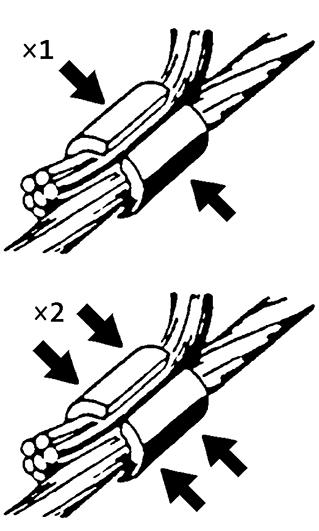
TBC89-B13 1 and 2 crimps. Through conductor
6-16 (C5) & 5-25 (C6) 6-16 (C5) & 5-25 (C6)
6-50 6-50
Total: 12-26 (C5), 30-50 (C6)
TBC5-C6 1
No C5 (Sleeve: C6-10) and C6 (Sleeve: C16-25)
Total: 50-100 (C89) TBC89-B13 2, 1 0,123 No C89 (Sleeve: C25-50) and B13 (KRF/KSF: 35 mm²)
For Al-terminals, indent crimping. Not used for pre-rounding.

Matrix holder TV2620, matrix TP13M, punch TP13D.
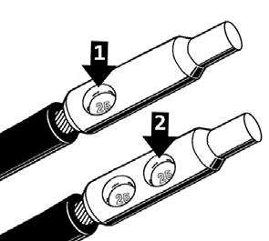
Crimp sequence
Stranded Al mm² Solid Al mm² Matrix Matrix holder Punch Number of crimps 16-25 16-35 TP13M TV2620 TP13D 2
Two crimps are always needed.
For crimping 16-25 mm² Al and 10-16 mm² Cu. Rotatable die, one side for crimping aluminum and the other side for crimping copper. Used in the V600 system.
Punch crimping.
The dies below are intended to be used together with Cu/Al conductors according to IEC 60228.
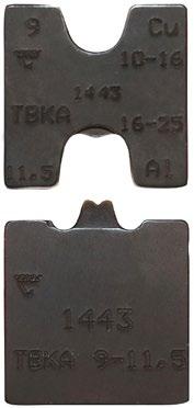
Stranded Al mm² mm² KR/KS, KRF/KSF Name Number of crimps Net weight (kg) Note 16-25 10-16 TBKA9-11,5 1 0,14 Used to crimp AS1625 and AKS1625-1016

Properties:
• patented crimping
• for crimping of flexible Cu conductors according to IEC 60228, type class 5
• used with Elpress KRF/KSF terminals
• for extra harsh environments such as cars and trains, where the terminals in addition to electrical properties are also exposed to, for example, corrosion, mechanical durability and vibration
• meets IEC/EN 61238:1
• meets corrosion requirements according to DIN V 40 046-37
• meets the requirements for vibration according to EN 50 155
• meets the requirements of mechanical strength according to SEN 24 50 10
Crimping sequence
Contact crimping takes place in a two-stage movement, first a hexagonal crimping that provides optimal symmetrical contact with the conductor, which means that no wires are broken or come apart in the edge facing the connector. This is followed by indent crimping, which provides 30% better electrical properties.
Tested and certified battery-powered crimp gun for contact crimping Cu-terminals, type KR/KRT 10 mm², KS/KST 10 mm², KRF/KRD/KRT 16-400 mm², KSF/KSD/KST 16-400 mm², Al-terminals 16-400 mm² (-240 solid), DIN 46235 10-300 mm², C sleeves up to 240 mm² total area (C95-120).
Properties:
• ergonomic design ensures optimum balance in the user’s hand
• crimp monitoring with warning light and signal when the correct pressure/full crimp is not achieved
• LED work lighting
• possibility of documentation of each crimp for unique service control
• crimp force 124 kN (13 tonnes)
• crimps/charging: 60-120 depending on size and temperature
• crimp time: 4-12s depending on size
• usage temperature -20°C to +40°C
• Li-Ion Makita, 5.0 Ah, 18V
• charger Li-Ion Makita, charging time 22 min 110-240VAC 50-60Hz
• DUAL: 10 - 300 mm²
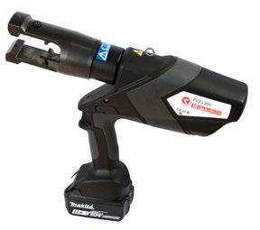
10-400 16-400 16-240 PVX1300 Punch, Dual, Hexagonal, Oval
10-400 16-400 16-240 PVX1300DB Punch, Dual, Hexagonal, Oval
10-400 16-400 16-240 PVX1300-ADV Punch, Dual, Hexagonal, Oval
10-400 16-400 16-240 PVX1300DB-ADV Punch, Dual, Hexagonal, Oval
10-400 16-400 16-240 PVX1300-WOBCADV Punch, Dual, Hexagonal, Oval
10-300 16-400 16-240 PVX1300-US Punch, Dual, Hexagonal, Oval
10-300 16-400 16-240 PVX1300DB-US Punch, Dual, Hexagonal, Oval
10-400 16-400 16-240 PVX1300-WOBC Punch, Dual, Hexagonal, Oval
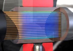
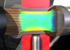
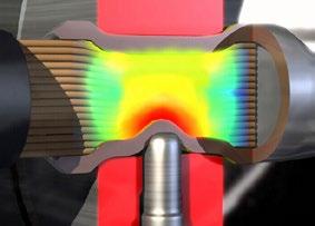

Delivered in CASE ADV.
with 2 batteries and CASE ADV.
in CASE ADV. and without Battery/Charger
Delivered with battery and US-charger
Delivered with 2 batteries and US-charger
without Battery/Charger
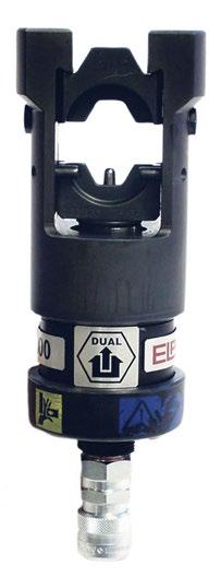
Crimp geometries
Tested and certified crimp head with patented DUAL technology for crimping Cu-terminals, type KR/KRF and KS/KSF 10-300 mm². Used in combination with foot pump P4000 or the electrically powered pump PS710 (battery powered version of PS710E is also available).
Properties:
• crimp head with the patented DUAL technology that provides optimised hexagonal crimping + a certain amount of indent crimping in two integrated steps
• working pressure 63 MPa (630 bar)
• crimp force 130 kN
• no die holders are needed for DUAL dies
• other accessories (without DUAL function) for crimping both Cu and Al-terminals can be used
• DUAL: 10 - 300 mm²
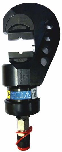
Crimp geometries
Crimp head with patented DUAL technology for crimping Cu-terminals, type KR/KRF and KS/KSF 10-300 mm². Used in combination with foot pump P4000 or the electrically powered pump PS710 (battery powered version of PS710E is also available).
Properties:
• crimp head for the patented DUAL technology that provides optimised hexagonal crimping + a indent crimping in two integrated steps
• working pressure 63 MPa (630 bar)
• crimp force 130 kN
• no die holders are needed for DUAL dies
• other accessories (without DUAL function) for crimping Cu can be used
• DUAL: 10 - 300 mm²
Tested and certified battery-powered crimp gun for crimping Cu-terminals, type Cu-terminals, type KR/KRT 10 mm², KS/KST 10 mm², KRF/KRD/KRT 16-400 mm², KSF/ KSD/KST 16-400 mm², C-sleeves up to 240 mm² total area (C95-120).
Properties:
• ergonomic design ensures optimum balance in the user’s hand
• crimp monitoring with warning light (LED) and signal when the correct pressure/ full crimp is not achieved
• LED work lighting
• possibility of documentation of each crimp for unique service control
• crimp force 124 kN (13 tonnes)
• usage temperature -20°C to +40°C
• Li-Ion Makita, 5.0 Ah, 18V
• charger Li-Ion Makita, charging time 22 min 110-240VAC 50-60Hz
• DUAL: 10 - 300 mm²
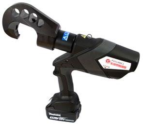

Crimp geometries


Crimp geometries
Tested and certified crimp head with patented DUAL technology for crimping Cu-terminals, type KRF/KSF 120-400 mm². Used in combination with foot pump P4000 or the electrically powered pump PS710 (battery powered version of PS710E is also available).
Properties:
• crimp head with the patented DUAL technology that provides optimised hexagonal crimping + a certain amount of indent crimping in two integrated steps
• working pressure 63 MPa (630 bar)
• crimp force 250kN (25 tonnes)
• large crimp area
• no die holders are needed for DUAL dies
• Other accessories (without DUAL function) for crimping both Cu and Al-terminals can be used
• DUAL: 120 - 400 mm²
Supplied in pairs.
For Cu-terminals, type KR/KRF and KS/KSF and flexible Cu conductors. No die holders are needed.
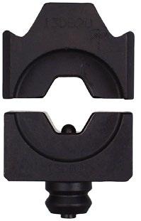
Die pair 13DB20.
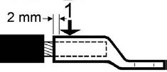

Crimp sequence for one crimp. Crimp sequence for two crimps.
mm² Name Number of crimps Net weight (kg)
10 13DB8 1 0,448
16 13DB9 1 0,447
25 13DB11 1 0,462
35 13DB13 1 0,477
50 13DB14,5 1 0,480
70 13DB17 1 0,486
95 13DB20 1 0,484
120 13DB22 2 0,441
150 13DB25 2 0,440
185 13DB27 2 0,443
240 13DB30 2 0,453
300 13DB32 2 0,428
Supplied in pairs.
For Cu-terminals, type KR/KRF and KS/KSF and flexible Cu conductors. No die holders are needed.
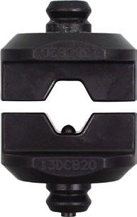
Die pair 13DCB20.
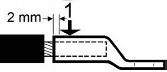
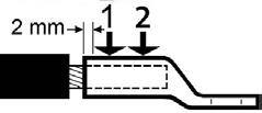
Crimp sequence for one crimp. Crimp sequence for two crimps.
mm² Name Number of crimps Net weight (kg)
10 13DCB8 1 0,456 16 13DCB9 1 0,440
25 13DCB11 1 0,465
35 13DCB13 1 0,486
50 13DCB14,5 1 0,497 70 13DCB17 1 0,503 95 13DCB20 1 0,507 120 13DCB22 2 0,450
150 13DCB25 2 0,498
185 13DCB27 2 0,514
240 13DCB30 2 0,534
300 13DCB32 2 0,490
Supplied in pairs. For Cu-terminals, type KR/KRF and KS/KSF and flexible Cu conductors. No die holders are needed.
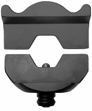
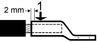

Crimp sequence for one crimp. Crimp sequence for two crimps.
mm² Name Number of crimps Net weight (kg)
120 DB2522 1 1,060
150 DB2525 1 1,060
185 DB2527 1 1,060
240 DB2530 1 1,060
300 DB2532 1 1,060
400 DB2538 2 1,060
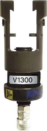
Crimp geometries
Tested and certified crimp head for crimping Cu-terminals, type KR/KRT 10 mm², KS/KST 10 mm², KRF/KRD/KRT 16-400 mm², KSF/KSD/KST 16-400 mm², Al-terminals 16-400 mm² (-240 solid), DIN 46235 10-300 mm², C sleeves up to 240 mm² total area (C95-120). Used in combination with foot pump P4000 or the electrically powered pump PS710 (battery powered version of PS710E is also available).
Properties:
• working pressure 63 MPa (630 bar)
• crimp force 130 kN (13 tonnes)
• versatile and easy-to-use steel crimp head

Crimp geometries
Tested and certified hydraulic hand-held tool for crimping Cu-terminals, type KR/KRT 10 mm², KS/KST 10 mm², KRF/KRD/KRT 16-400 mm², KSF/KSD/KST 16-400 mm², Al terminals 16-400 mm² (-240 solid), DIN 46235 10-300 mm², C-sleeves up to 240 mm² total area (C95-120).
Properties:
• fast forward feeding
• crimp force 130 kN (13 tonnes)
• requires low handle force, approx 245 N at max force
• the fork can rotate 180°
(Stranded Al)
(Solid Al)
16-400
Tested and certified battery-powered crimp gun for contact crimping Cu-terminals, type KR/KRT 10 mm², KS/KST 10 mm², KRF/KRD/KRT 16-400 mm², KSF/KSD/KST 16-400 mm², Al-terminals 16-400 mm² (-240 solid), DIN 46235 10-300 mm², C sleeves up to 240 mm² total area (C95-120).
Properties:
• ergonomic design ensures optimum balance in the user’s hand
• crimp monitoring with warning light and signal when the correct pressure/full crimp is not achieved
• LED work lighting
• possibility of documentation of each crimp for unique service control
• crimp force 124 kN (13 tonnes)
• crimps/charging: 60-120 depending on size and temperature
• crimp time: 4-12s depending on size
• usage temperature -20°C to +40°C
• Li-Ion Makita, 5.0 Ah, 18V
• charger Li-Ion Makita, charging time 22 min 110-240VAC 50-60Hz
• DUAL: 10 - 300 mm²


10-400 16-400 16-240 PVX1300-WOBCADV Punch, Dual, Hexagonal, Oval
16-400 16-240 PVX1300DB-US Punch, Dual, Hexagonal, Oval
10-400 16-400 16-240 PVX1300-WOBC Punch, Dual, Hexagonal, Oval

The B dies below are intended for Cu-terminals, type KR/KRF and KS/KSF, together with both stranded, multi-stranded and very flexible Cu conductors of Class 2, 5 and 6 respectively according to IEC 60228. For multi-stranded (Class 5) Cu conductors, crimping is recommended with the Dual system. KRD/KSD and KRT/KST are only used for stranded (Class 2) Cu conductors.
For Cu-terminals, hexagonal crimping. Supplied in pairs.
The B dies below are intended for Cu-terminals, type KR/KRF and KS/KSF, together with Cu conductors according to IEC 60228. For multi-stranded (Class 5) and very flexible (Class 6) Cu conductors, crimping with the Dual system is recommended.
Use inner die holder V1316 and outer die holder V1318
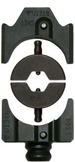
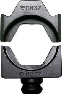
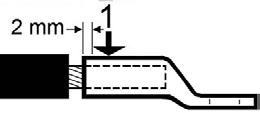
Outer die holder V1318, B-dies, inner die holder V1316. Integrated dies 13B32. Crimp sequence for one crimp.
For Cu-terminals, hexagonal crimping. Supplied in pairs. The integrated B dies below are intended for Cu-terminals, type KR/KRF and KS/KSF, together with Cu conductors according to IEC 60228. For multi-stranded (Class 5) and very flexible (Class 6) Cu conductors, crimping with the Dual system is recommended. Used without a die holder.
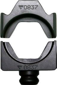
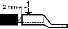

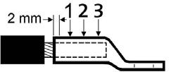
Integrated dies 13B32. Crimp sequence for one crimp. Crimp sequence for two crimps. Crimp sequence for three crimps.
mm² Name Number of crimps Net weight (kg)
10 13B8 1 0,438
16 13B9 1 0,445 25 13B11 1 0,460
35 13B13 1 0,475
50 13B14,5 1 0,471
70 13B17 1 0,465 95 13B20 1 0,473
13B22
For Cu-terminals, hexagonal crimping. Supplied in pairs. The B dies below are intended for Cu-terminals, type KRD and KSD, together with Cu conductors class 2 according to IEC 60228. Use inner die holder V1316 and outer die holder V1318
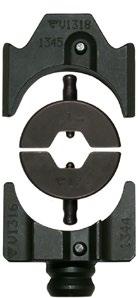
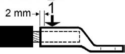
Outer die holder V1318, B-dies, inner die holder V1316. Crimp sequence for one crimp.
mm²
KRD/KSD
For Cu-terminals, hexagonal crimping. Supplied in pairs. The integrated B dies below are intended for Cu-terminals, type KRD and KSD, together with Cu conductors Class 2 according to IEC 60228. Used without a die holder.

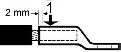

Integrated dies 13B32. Crimp sequence for one crimp. Crimp sequence for two crimps.
mm²
For Cu-terminals, hexagonal crimping. Supplied in pairs. The B dies below are intended for Cu-terminals, type KRT and KST, together with Cu conductors class 2 according to IEC 60228. Use inner die holder V1316 and outer die holder V1318
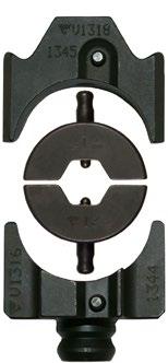

Outer die holder V1318, B-dies, inner die holder V1316. Crimp sequence for one crimp.
mm² KRT/KST
For Cu-terminals, hexagonal crimping. Supplied in pairs. The integrated B dies below are intended for Cu-terminals, type KRT and KST, together with Cu conductors Class 2 according to IEC 60228. Used without a die holder.
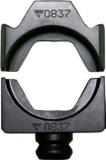
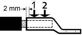
Integrated dies 13B32. Crimp sequence for two crimps. mm²
13B24 2 0,001 240 13B26 2 0,420
300 13B30 2 0,413 400 13B32 2 0,408
For Cu branching with C-sleeves, oval crimping. Unless otherwise stated, use inner die holder V1316, and outer die holder V1318
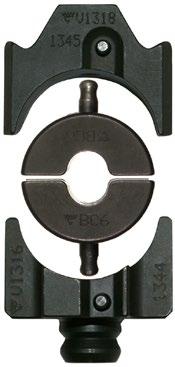

Outer die holder V1318, BC dies, inner die holder V1316. One and three crimps.
Outer and inner holder for the 1300 system.
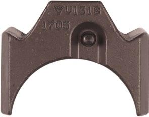
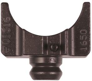
Net weight (kg)
V1316 0,197 V1318 0,309
A safer, more durable and easier to handle case for Elpress crimping tools, PVX1300 and PVX1300C2. CASE ADVANCED can handle the most demanding conditions. The case is IP67 rated, withstands dust and heavy impacts. Pull handles and wheels make it easier for the user to transport the tool and the right accessories.
Properties:
• lifetime warranty.
• handles can withstand up to 30 kg.
• compartment for easy storage of dies, matrices and punches.
• withstands temperatures from -30 °C up to +90 °C.
• the case can be locked with double padlocks.
• pressure equalisation valve.
• IP67 (fully waterproof to a depth of 1 metre).
• STANAG4280, DEF-STAN 81-41 Certification.
Name Net weight (kg)
PVX1300-CASE-ADV 7,6
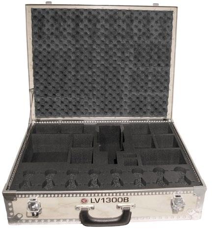
Storage box that holds the V1300 tool and accessories to crimp Elpress Cu-terminals.
Properties:
• material plywood
• interior material polyethylene
• solid, moulded interior

Additional storage box for accessories for PVX1300. The box holds all the accessories needed when working with the 1300 system from Elpress. The box holds space for 14 B-dies, 1-2 die holders, 12-14 integrated B-dies (DUAL-die pairs), 4 punches (AL crimping), 8 pre-rounding punches and 3 matrixes as well as a matrix holder (example). The box is designed together with the L-PVX1300, and is advantageously used with this box.
Properties:
• material plywood
• interior material polyethylene
• solid, moulded interior
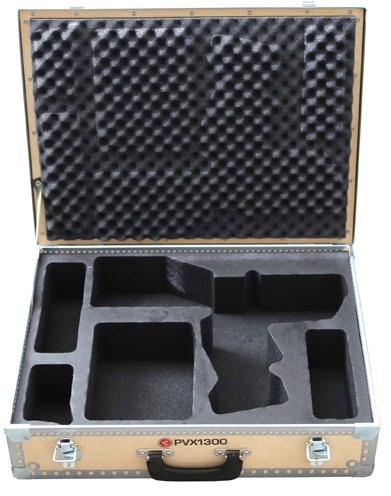
Additional storage box for PVX1300. The box is designed to hold PVX1300 with charger and an extra battery. there’s also extra space for a few dies, stripping tool and terminals. The box is designed together with the L1300 CU-ALU and is advantageously used together.
Properties:
• material plywood
• interior material polyethylene
• solid, moulded interior
For Al-terminals, indent crimping. For the indent crimping of Al-terminals, two crimps are always required. For 16-150 (185 solid) mm² use matrix holder V1320.
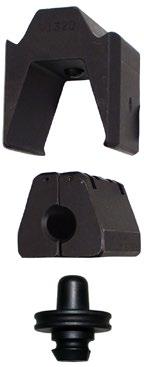

Matrix holder V1320, matrix P13M, punch P13D. Crimp sequence
Stranded Al mm² Solid Al mm² Matrix Punch
Number of crimps Matrix holder required Punch holder required Note 16-25 16-35 P13M P13D 2 Yes No 35-70 50-95 P20M P20D 2 Yes No 95-150 120-185 P25M P25D 2 Yes No 185-240 240 13P32M P32D 2 No No 300-400 13P37M 13P37D 2 No No
Matrix with safety line. For Al-terminals, type AKKxxxB/AKSxxxB and sleeves type ASxxxB.
For Al conductors, pre-rounding. Use matrix holder V1320
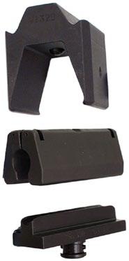
Matrix holder V1320, matrix R6MR, punch 13R6DR.
Stranded Al mm² Solid Al mm² Matrix Punch Number of crimps Matrix holder required Punch holder required
16 16 (+25) R6MR 13R6DR 1
25 35 R7MR 13R7DR 1
35 50 R8MR 13R8DR 1
50 70 R9MR 13R9DR 1
70 95 R12MR 13R12DR 1
No
No
No 95 120 R13MR 13R13DR 1
No 120 150 R15MR 13R15DR 1
No 150 185 R16MR 13R16DR 1
No 185 240 13R18MR 13R18DR 1
No 240 13R20MR 13R20DR 1
Matrix holder for non-integrated matrix. Punch holder not required for the 1300 system.
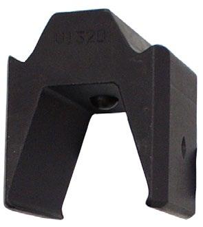
For Al-connectors 50-240 mm², indent crimp, both round- and sector shaped conductors. Without need for pre-rounding of sector shaped conductors. Used without matrix holder.
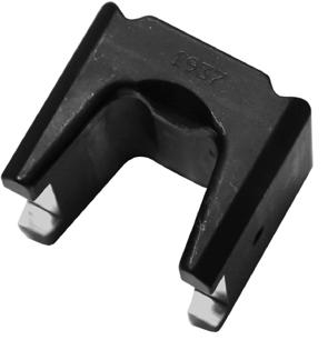
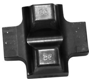
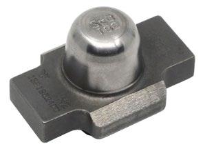
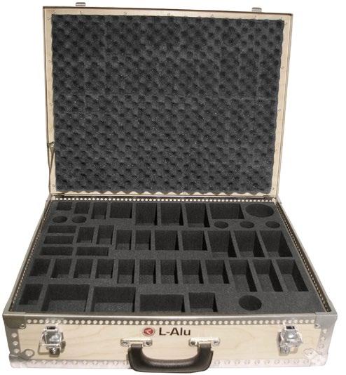
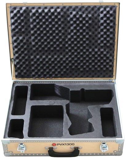

Additional storage box for LV1300B and LV250, with space for accessories to crimp Elpress Al-terminals.
Properties:
• material plywood
• interior material polyethylene
• solid, moulded interior
Additional storage box for PVX1300. The box is designed to hold PVX1300 with charger and an extra battery. there’s also extra space for a few dies, stripping tool and terminals. The box is designed together with the L1300 CU-ALU and is advantageously used together.
Properties:
• material plywood
• interior material polyethylene
• solid, moulded interior
Additional storage box for accessories for PVX1300. The box holds all the accessories needed when working with the 1300 system from Elpress. The box holds space for 14 B-dies, 1-2 die holders, 12-14 integrated B-dies (DUAL-die pairs), 4 punches (AL crimping), 8 pre-rounding punches and 3 matrices as well as a matrix holder (example). The box is designed together with the L-PVX1300, and is advantageously used with this box.
Properties:
• material plywood
• interior material polyethylene
• solid, moulded interior
Supplied in pairs. Hexagonal crimping. Use inner die holder V1316, and outer die holder V1318.
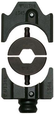
Outer die holder V1318, BNP dies, inner die holder V1316.
mm²
Overhead line Name Number of crimps Net weight (kg) Die holder required Note
31-62 B16NP 2x5 0,118 Yes
99 B20NP 2x5 0,126 Yes
157 13B26 2x16 0,420 No
241 13B32 2x16 0,408 No
Supplied in pairs. BxxFE dies are used for steel sleeves and BxxNP dies are used for Al-sleeves. Use inner die holder V1316 and outer die holder V1318
Die pair B16NP
mm² Die Fe Die Al Number of crimps
62 B6FE B16NP 2x5
99 B8FE B20NP 2x5
AlMgSi 31-62 mm², FeAL: 62 mm², ALUS 50 mm²
AlMgSi 99 mm², FeAL: 99 mm²
Overhead line: 157 mm² (2x16 crimps)
Overhead line: 241 mm² (2x16 crimps)
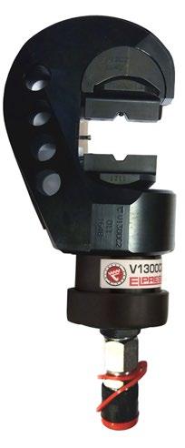
Crimp geometries
Tested and certified crimp head for crimping Cu-terminals, type KR/KRT 10 mm², KS/KST 10 mm², KRF/KRD/KRT 16-400 mm², KSF/KSD/KST 16-400 mm². Used in combination with foot pump P4000 or battery and mains powered pump PS710 (battery powered version of PS710E is also available).
Properties:
• working pressure 63 MPa (630 bar)
• crimp force 130 kN
• versatile and easy to use
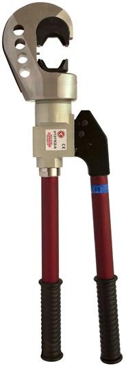
Tested and certified hydraulic hand-held tool for crimping Cu-terminals, type KR/KRT 10 mm², KS/KST 10 mm², KRF/KRD/KRT 16-400 mm², KSF/KSD/ KST 16-400 mm².
Properties:
• fast forward feeding
• the fork can rotate 180°
• crimp force 130 kN
• requires low handle force, about 245N at maximum force
• easy to carry and work with
Storage box supplied with the V1311C2-A and V1311-A tools.
Tested and certified battery-powered crimp gun for crimping Cu-terminals, type KR/KRF and KS/KSF 10-400 mm², C-sleeves up to 240 mm² total area (C95-120).
Properties:
• ergonomic design ensures optimum balance in the user’s hand
• crimp monitoring with warning light and signal when the correct pressure/full crimp is not achieved
• LED work lighting
• possibility of documentation of each crimp for unique service control
• crimp force 124 kN (13 tonnes)
• usage temperature -20°C to +40°C
• Li-Ion Makita, 5.0 Ah, 18V
• charger Li-Ion Makita, charging time 22 min 110-240VAC 50-60Hz
• DUAL: 10 - 300 mm² Crimp geometries


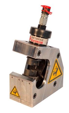
TS1300 with crimp head
The TS1300 is a table stand that can be used with crimp heads DV1300C2 or V1300C2-AL.
The table stand is designed for operators with high frequency use of the C2 crimp head. With the table stand you get a stable, safe and easy use of the C2 crimp head.
mm² Name Crimp geometries
10-400 TS1300CU Dual, Hexagonal, Oval 18,7
16-400 TS1300AL Punch
10-400 TS1300
The B dies below are intended for Cu-terminals, type KR/KRF/KRD/KRT and KS/KSF/KSD/KST, together with both stranded and multi-stranded Cu conductors of Class 2 according to IEC 60228. For multi-stranded (Class 5) Cu conductors, crimping is recommended with the Dual system.
Supplied in pairs. For Cu-terminals, hexagonal crimping. Used with die holder V1330
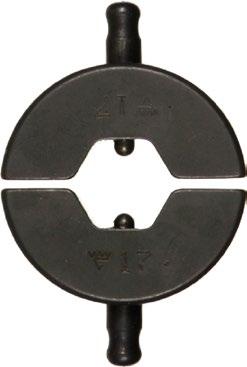

B dies. Crimp sequence for one crimp.
Supplied in pairs.
For Cu-terminals, hexagonal crimping. Used without a die holder.
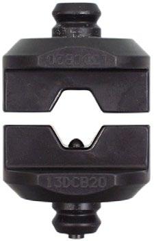


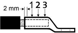
13CB20 Crimp sequence for one crimp. Crimp sequence for two crimps. Crimp sequence for three crimps.
mm² KR/KS, KRF/KSF
No
13CB9 1 0,446 No
13CB11 1 0,468 No
13CB13 1 0,488 No
13CB14,5 1 0,481 No
13CB17 1 0,480 No
13CB20 1 0,497 No
13CB22 1 0,537 No 150 13CB25 2 0,474 No 185 13CB27 2 0,478 No 240 13CB30 2 0,535 No 300 13CB32 2 0,491 No 400 13C21B38 3 0,450 No Used in V1300C2 but NOTE that V13C21 must be in the crimp head/fork.
For Cu-terminals, hexagonal crimping. Supplied in pairs. The B dies below are intended for Cu-terminals, type KRD and KSD, together with Cu conductors class 2 according to IEC 60228. Used with die holder V1330.


B dies. Die holder V1330 (pair). Crimp sequence for one crimp.
Supplied in pairs.
For Cu-terminals, hexagonal crimping. Used without a die holder.
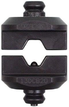
mm²


Crimp sequence for one crimp. Crimp sequence for two crimps.
KRD/KSD Name Number of crimps Net weight (kg)
16 13CB8 1 0,434
25 13CB9 1 0,446
35 13CB11 1 0,468
50 13CB12 1 0,466 70 13CB14 1 0,483
70 13CB16 1 0,484 120 13CB19 1 0,500
150 13CB22 1 0,537
185 13CB25 2 0,474
240 13CB27 2 0,478
300 13CB30 2 0,535
400 13CB32 2 0,491
For Cu-terminals, hexagonal crimping. Supplied in pairs. The B dies below are intended for Cu-terminals, type KRD and KSD, together with Cu conductors class 2 according to IEC 60228. Used with die holder V1330.


B dies. Die holder V1330 (pair). Crimp sequence for one crimp.
mm²
KRT/KST Name Number of crimps Net weight (kg) Die holder required
10 B7 1 0,101 Yes 16 B8,5 1 0,101 Yes 25 B10 1 0,106 Yes 35 B12 1 0,108 Yes 50 B14 1 0,112 Yes 70 B16 1 0,107 Yes 95 B18 1 0,120 Yes
B19 1 0,118 Yes 150 B22 1 0,148 Yes 185 B24 1 0,139 Yes
Supplied in pairs. For Cu-terminals, hexagonal crimping. Used without a die holder.


Crimp sequence for one crimp. Crimp sequence for two crimps.
For Cu branching with C-sleeves, oval crimping. Unless otherwise stated, use die holder V1330
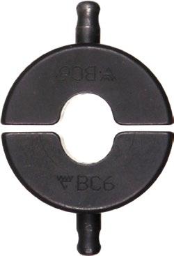

Supplied in pairs.

Die holder V1330 (pair).
Name Net weight (kg)
V1330 0,43
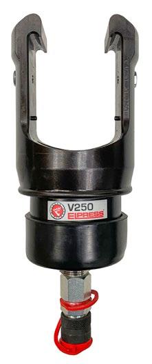
Crimp geometries
Tested and certified crimp head for crimping Cu-terminals, type KR/KRT 10 mm², KS/ KST 10 mm², KRF/KRD/KRT 16-800 mm², KSF/KSD/KST 16-800 mm², Al-terminals 16-630 mm² (-300 solid), C sleeves 6/6-300/300 mm². Used in combination with foot pump P4000 or the electrically powered pump PS710 (battery powered version of PS710E is also available).
Properties:
• working pressure 63 MPa (630 bar)
• crimp force 250kN (25 tonnes)
• large crimp area, 10-800 mm²
The B dies are intended for Cu-terminals, type KR/KRF and KS/KSF, together with stranded Cu conductors of Class 2 according to IEC 60228. For multi-stranded (Class 5) Cu conductors, crimping with the Dual system is recommended.
Supplied in pairs. For Cu-terminals, KRF/KSF, hexagonal crimping. If die holders are required, use inner die holder V2506 and outer die holder V2508
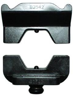
Die pair B2542, used without die holder.

sequence for one crimp.


sequence for two crimps.
sequence for three crimps. mm²
Supplied in pairs. For Cu-terminals, KRD/KSD, hexagonal crimping. If die holders are required, use inner die holder V2506 and outer die holder V2508.
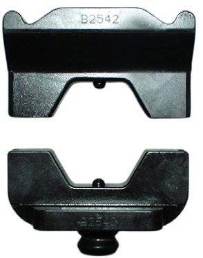


Die pair B2542, used without die holder. Crimp sequence for one crimp. Crimp sequence for two crimps. Crimp sequence for three crimps.
mm²
Supplied in pairs. For Cu-terminals, KRT/KST, hexagonal crimping. If die holders are required, use inner die holder V2506 and outer die holder V2508.


Die pair B2542, used without die holder. Crimp sequence for one crimp. Crimp sequence for two crimps. Crimp sequence for three crimps. mm²
Die pair for Cu-branching with C-sleeves, oval crimping. If a die holder is required, use inner die holder V2506 and outer die holder V2508, for the V250 system.

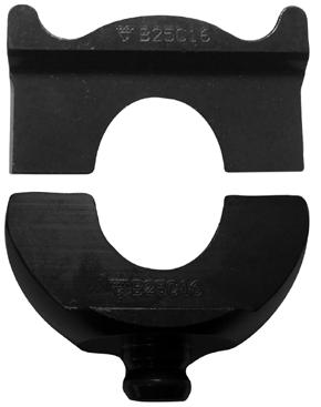
Die holder V2508, BC dies, die holder V2506. Die pair B25C16

One and two crimps.
Inner and outer die holder for the 250 system.

V2506 0,341
V2508 0,632
For indent crimping of Al-terminals and connectors. Two crimps are always needed, see image. For solid (Class 1) and solid (Class 2) Al-conductors according to IEC 60228. (no punch holder is needed)
Matrix holder V2521, matrix P13M, punch P13D.

Crimp sequence
Stranded Al mm² Solid Al mm² Matrix Matrix holder Punch Number of crimps Used for
16-25 16-35 P13M V2521 P13D 2
35-70 50-95 P20M V2521 P20D 2
95-150 120-185 P25M V2521 P25D 2
185-240 240 P32M V2531 P32D 2
300 300 P36M V2531 P36-40-44D 2
300-400 P2537M P2537D 2
400 P40M V2531 P36-40-44D 2
500 P44M V2531 P36-40-44D 2
500-630 P2552M P2552D 2
Terminals and through connectors of type AK/AS/AKK/AKS 300B-400B
Terminals and through connectors of type AK/AS/AKK/AKS 500B
Terminals and through connectors type AK/AS/AKK/AKS 500A
For Al conductors, pre-rounding. Use punch holder V2540
Matrix holder V2531, matrix R18MR, punch R18DR, punch holder V2540.
Stranded Al mm² Solid Al mm² Matrix Matrix holder Punch
16 16 (+25) R6MR V2521 R6DR
25 35 R7MR V2521 R7DR
35 50 R8MR V2521 R8DR
50 70 R9MR V2521 R9DR
70 95 R12MR V2521 R12DR
95 120 R13MR V2521 R13DR
120 150 R15MR V2521 R15DR
150 185 R16MR V2521 R16DR
185 240 R18MR V2531 R18DR
240 R20MR V2531 R20DR
300 300 R21MR V2531 R21DR
400 R26MR V2531 R26DR
500 R28MR V2531 R28DR
Matrix- and punch holder for the 250 system.
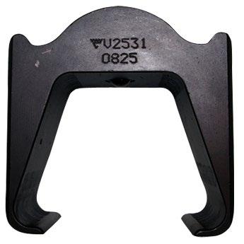
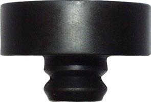
Supplied in pairs. For joints on overhead lines AlMgSi (Super B) and Al59, hexagonal crimping. Use inner die holder V2506 and outer die holder V2508.

Die holder V2508, BNP dies, die holder V2506.
mm²
Supplied in pairs. BxxFE dies are used for steel sleeves and BxxNP dies are used for Al-sleeves. Use inner die holder V2506 and outer die holder V2508.

mm² Die Fe Die Al
62 B6FE B16NP 2x5
99 B8FE B20NP 2x5
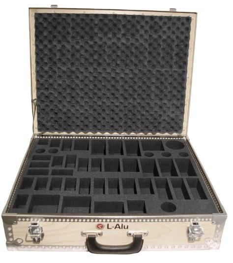
Additional storage box for LV1300B and LV250, with space for accessories to crimp Elpress Al-terminals.
Properties:
• material plywood
• interior material polyethylene
• solid, moulded interior
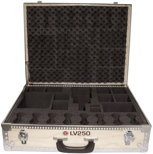
Storage box with space for tool V250 and all necessary accessories to crimp Elpress Cu-terminals.
Properties:
• material plywood
• interior material polyethylene
• solid, moulded interior

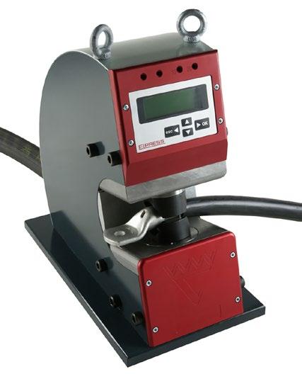
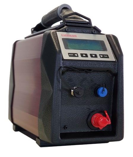
Elpress crimp station CS2500 offers efficient production with the greatest possible personal safety. Advanced, intelligent properties combined with simplicity make the product unique.
Properties:
• designed for continuous production of electric Cu-terminals, 10-300 mm²
• quick locking of the terminal using low force shortens the overall time for crimping
• automatic setting of crimp force up to 250 kN, provides optimal service life for tools and accessories
• only one crimp necessary throughout the work area
• integrated Elpress DUAL System
• hydraulic pump PS710D with control, monitoring and error reporting
• operated with a foot pedal
• CE approved, meets the requirements of the Safety of machinery directive
• software Analyzer for analysis and report printout of crimps
• 110-240VAC 50-60Hz
Supplied in pairs.
For Cu-terminals, type KR/KRF and KS/KSF and flexible Cu conductors, no die holders are required.
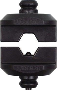
Die pair 13DCB20.
mm² Name Number of crimps Net weight (kg)
10 13DCB8 1 0,456 16 13DCB9 1 0,440 25 13DCB11 1 0,465 35 13DCB13 1 0,486
50 13DCB14,5 1 0,497 70 13DCB17 1 0,503 95 13DCB20 1 0,507 120 20DCB22 1 0,599 150 20DCB25 1 0,599
185 20DCB27 1 0,591
240 20DCB30 1 0,587
300 20DCB32 1 0,564
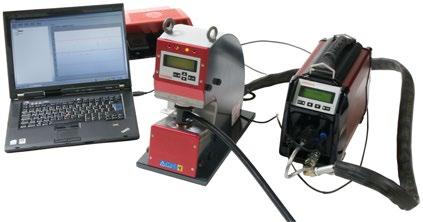
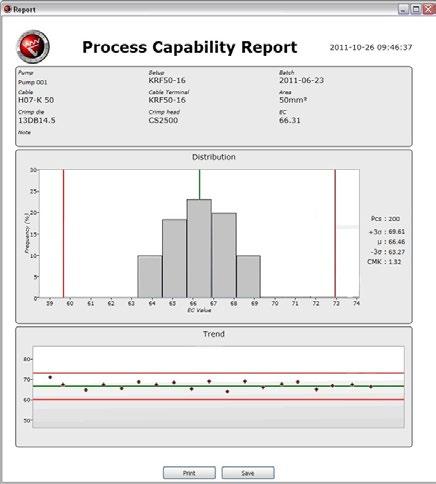
Analyzer, measures and analyses each individual crimp.
The Analyzer program is used to ensure quality crimps and save data to quality documents. By simple means, all crimps can be studied in a PC environment where they get their own ID number for full traceability. The unique SPC tool, Statistic Process Control, makes it possible to consider crimping as a measurable process. Analyzer is a statistical program for systematic studies of variations in the crimp process. Furthermore, you can export, import, print or save graphs, calibration data, batch reports etc.
Properties:
• Elpress Analyzer improves overall quality
• helps the user
• provides a process improvement tool
• measures and shows all crimps
• supports preventive maintenance of equipment
• creates traceability and documentation
• makes communication easy
• increases user skills
• eliminates incorrect crimps
• comes with instructions for use
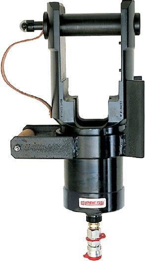
Crimp geometries
Tested and certified crimp head for contact crimping Cu-terminals, type KRF/KSF 500-800 mm², KRD/KSD, KRT/KST 500-1000 mm², Al-terminals 800-1200 mm², C-sleeves 245-540 mm² (C150-185 och C240-300). Used in combination with foot pump P4000 or electrically powered pump PS710.
Properties:
• working pressure 63 MPa (630 bar)
• crimp force 400 kN
• supplied in plywood box
mm² (Cu) mm² (Stranded Al) Name Crimp geometries
(kg)
500-1000 800-1200 V1470 Punch, Hexagonal, Oval 20,76
Supplied in pairs. For Cu-terminals, hexagonal crimping. When crimping Cu-terminals, two crimps are always required. Flexible conductors in KRF/KSF and stranded conductors in KRD/KSD/KRT/KST.
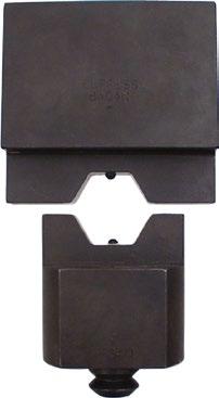

B4040. Crimp sequence for two crimps.
mm²
500 B4040 2 4,011 No For stranded Cu-conductors: KRD/KSD, KRT/KST 500 mm²
500 B4042 2 4,067 No For multi strand Cu-conductors: KRF/KSF 500 mm²
630 B4045 2 3,959 No For stranded Cu-conductors: KRD/KSD, KRT/KST 630 mm²
630-800 B4053 2 3,901 No For multi strand Cu-conductors: KRF/KSF (and stranded Cu conductors 800 mm²: KRD/KSD/KRT/KST)
1000 B4056 2 3,670 No For stranded Cu-conductors: KRD/KSD, KRT/KST
Supplied in pairs. For Cu branching with C-sleeve, oval crimping. Only one crimp is required for Cu branches with C-sleeve.
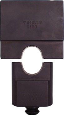
For Al-terminals, indent crimping. Use matrix holder V1471 When crimping Al-terminals, two crimps are always required.
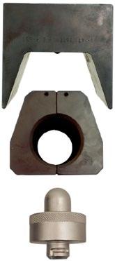

Matrix holder V1471, Matrix W60M, punch W60D. Crimp sequence
Stranded Al mm² Matrix Punch Number of crimps
800-1000 W60M W60D 2 Yes No 1200 W70M W70D 2 Yes No
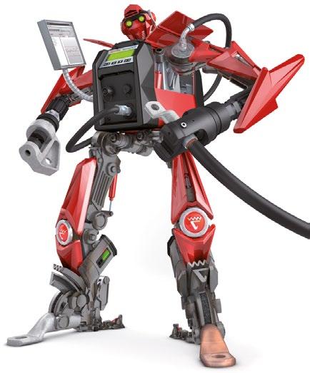
PS710
The PS710 is an electrically driven pump for crimping with advanced control and monitoring of crimping progress. A flexible system for a wide range of applications with high performance and reliability for professional use. The pump is suitable for cabling manufacturers as well as for fitters working in the field. The PS710 can be used for all types of crimping or cutting. The PS710 has a power source for all types of crimping.
Technical data:
• possibility to use different pressure ranges, 0 - 700 Bar
• can be used with a PC on a computer network with a printer, does not apply to the PS710R
• oil flow at 20 bar: 0.6 litre/min (PS710D 1.2 litre/min)
• oil volume: 1.0 litre
• oil type: HYDREX MV 22 or similar
• crimps/battery charge: 120 crimps with Cu 150 mm²
• ambient temperature: -22 to 55°C
• protection: IP54
• mains operation 85-276VAC 50-60Hz
• Li-ion battery 28,8V, 3,0 Ah
• meet CE requirements: Safety of machinery 2006/42/EC, Electromagnetic compatibility 2014/30/EU, Low Voltage Directive 2014/35/EU, ROHS 2014/35/EU, WEEE 2012/19/EU
• weight approx. 12,4 kg
• compact dimensions 370 x 170 x 280 mm
The pump consists of three basic versions, each with customisation options.

• For cabling manufacturers. used with crimping station CS2500
Properties:
• unique electronic control system together with special PC software
• analysis and process monitoring/control, SPC, for tracking each crimp
• LCD Display with keypad for full status information of pump to the fitter
• communication with PC in real time provides instant quality control
• integrated communication via CAN with Elpress CS2500
• high flow hydraulic pump for fastest possible crimping
• can be used with PC on a computer network with printer
Name Net weight (kg) Length mm Width Height
PS710D 12,4 370 170 280

For fitters working in the distribution network or industry.
Properties:
• small and light weight, which makes the product easy to use in every situation
• maximum performance, can be used both with Li-ion battery 28.8 V or 220V mains power
• LCD Display with keypad for full status information of pump to the fitter
• able to store and document crimps in the control system
• PC communication via USB
• to be used with crimp heads and cable cutters
• Elpress ergonomic handle ERGOCOM, with wireless communication can be selected for
• charger 230 VAC 50 Hz, 10.8-28.8 V, charging time 65 min
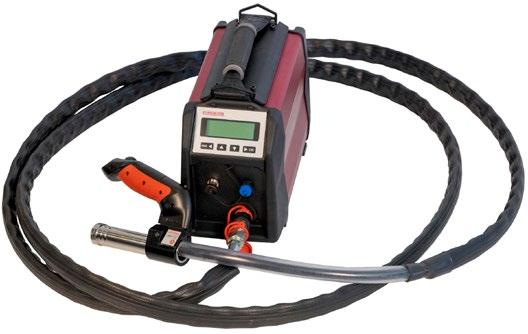
Contains:
• pump E-version
• cable
• hydraulic hose 2.4 m or 5.0 m with wireless communication ERGOCOM
• battery
• charger
• carrying strap
• 110-240VAC 50-60Hz Name
PS710E251 24,5
PS710E501 26,0
PS710E501-US 26,0
PS710E251-US 24,5
PS710E pump with carrying strap. Ergocom hose 2.4 m and power cord EU, battery and charger
170 280 PS710E pump with carrying strap. Ergocom hose 5.0 m and power cord EU, battery and charger
170 280 PS710E pump with carrying strap. Ergo hose 5.0 m and power cord US, battery and charger
170
PS710E pump with carrying strap. Ergo hose 2.4 m and power cord US, battery and charger
ERGOCOM hoses are not available in US/North American market.
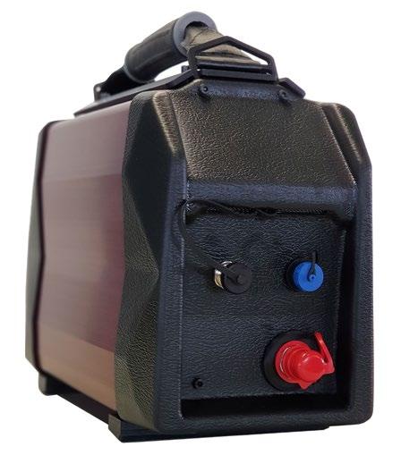
For users looking for a reliable standard product (without the need for documented traceability).
Properties:
• pump control without electronic control system, relay controlled
• easily equipped without data communication
• without battery
• to be used with crimp heads and cable cutters
• Elpress ergonomic handle ERGO, with wired communication can be selected for
• 110-240VAC 50-60Hz
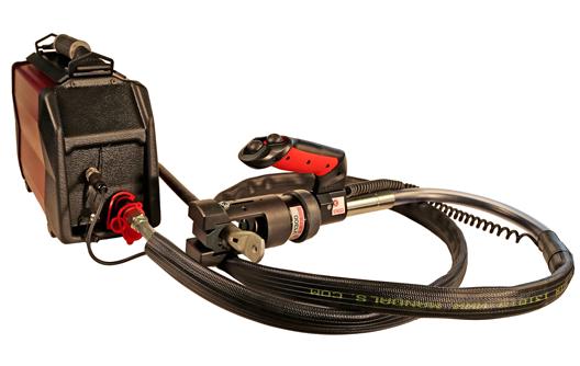
Contains:
• pump R version
• cable
• hydraulic hose 2.4 or 5.0 m with wired communication ERGO
• carrying strap
PS710R250
PS710R pump with carrying strap. Ergo hose 2.4 m and power cord EU PS710R500
PS710R250-US
PS710R500-US
PS710R pump with carrying strap. Ergo hose 5.0 m and power cord EU
PS710R pump with carrying strap. Ergo hose 2.4 m and power cord US
pump with carrying strap. Ergo hose 5.0 m and power cord US
Operating handle for operation of pump PS710. Ergonomically designed handle that reduces the load on the operator at the workstation. ERGOCOM is controlled via Bluetooth and ERGO is wired. Available in different designs depending on the length of the hydraulic hose.
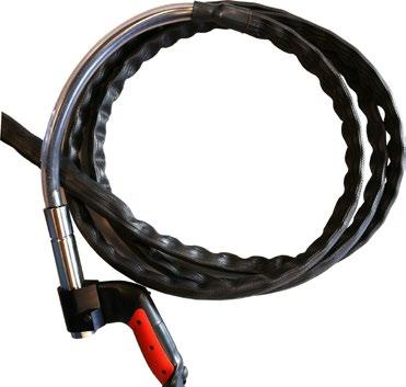
Name
Pcs/ pack Note
HYD.SLANG KPL. 2,4M ERG PS710E 1
HYD.SLANG KPL. 5M ERGO PS710E 1
HYD.SLANG KPL.2,4M ERGO PS710R 1
HYD.SLANG KPL. 5M ERGO PS710R 1
HYD.SLANG KPL. 2,4M ERGOCOM 1
HYD.SLANG KPL. 5M ERGOCOM 1
Hydraulic hose (2.4 m) for PS710E, with ERGO handle
Hydraulic hose (5 m) for PS710E, with ERGO handle
Hydraulic hose (2.4 m) for PS710R, with ERGO handle
Hydraulic hose (5 m) for PS710R, with ERGO handle
Hydraulic hose (2.4 m) for PS710R, with ERGOCOM handle (bluetooth)
Hydraulic hose (5 m) for PS710R, with ERGOCOM handle (bluetooth)
FCU-PS710R 1 Foot pedal for PS710R
FCU-PS710D&E 1 Foot pedal for PS710D and PS710E
BÄRREM PS710 1
Carrying strap for all PS710 versions
ERGOCOM hoses are not available in US/North American market
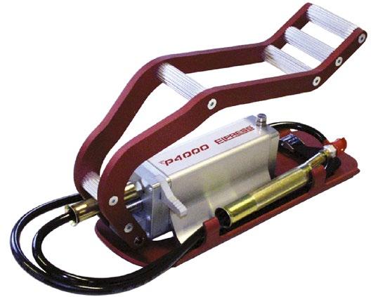
Properties:
• unique version in high strength aluminium alloy
• ergonomic design
• smooth, anodised (electro-oxidised) surfaces – easy to keep clean
• highly efficient, two-stage pump system with fast feed
• single foot-operated pressure relief (tool return) after automatic stop when crimping is complete
• 2.2 m hose with quick coupling
• standard pressure setting 630 bar/63 MPa, (max. setting 700 bar)
• safety valve for return at all pressures
• smooth transport mode for the hose
• special output for pressure monitoring

System Elpress
System Elpress consists of terminals and tools that are designed and tested together to give a certified crimping result. This ensures that users will feel confident when using our systems, and that a secure connection will be achieved through the proper handling of our products.
The Elpress program for overhead line connectors includes products for splicing copper lines, alloyed aluminium lines type AlMgSi (Super B) and Al59, as well as for FeAl lines. In addition to the wellknown copper and aluminium twist connectors, we also offer LFS and LFEAL contact crimp connectors that are crimped using the Elpress V600, V1300 and V250 systems. The LFS and LFEAL contact crimp connectors and Elpress System have been tested against requirements according to SS 4241241.
Properties:
• material copper
• for wire and line, see table
• the joint is rotated so that it is screwed in the opposite direction to the turn of the line
• tool: wrench
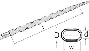
Properties:
• material aluminium
• the joint is rotated so that it is screwed in the opposite direction to the turn of the line
• tool: wrench
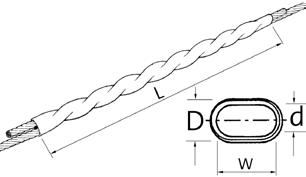
Properties:
• material aluminium
• for splicing overhead lines
• meets the requirements of SS 4241241
• the connector tube is supplied with contact paste on the inside
• the conductor must be cleaned
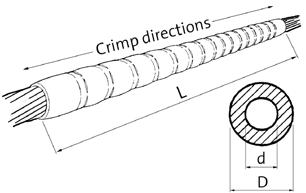
Crimp sequence, see picture. 2x10 crimps are required when crimping LFS99 with T2600, V600, V611 and PVX611.
Properties:
• outer Al-sleeve + inner steel sleeve for the centre strands
• meets the requirements of SS 4241241
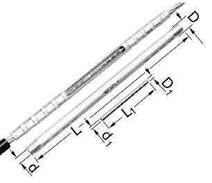
Elpress logotype is included on the marking. Marking XXXX = Year, week. Crimp sequence, see picture.
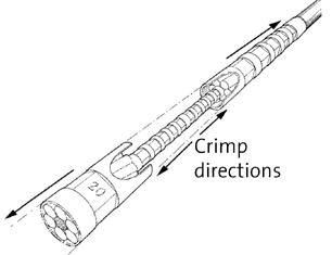

Crimp geometries
Cu-terminals
Tested and certified crimp head for crimping Cu-terminals, type KR/KS 10 mm², KRF/KSF 16-150 mm², KRD/KSD 16-185 mm², KRT/KST 10-240 mm², Al-terminals 16-25 mm² (-35 solid), C-sleeves 6/6-50/50 mm², DIN 46235 10-95 mm². Used in combination with foot pump P4000 or the electrically powered pump PS710 (battery powered version of PS710E is also available).
Properties:
• working pressure 63 MPa (630 bar)
• crimp force 55 kN
• robust fabric bag with room for 10 dies included

Crimp geometries
Tested and certified hand-held tool for crimping Cu-terminals, type KR/KS 10 mm², KRF/ KSF 16-150 mm², KRD/KSD 16-185 mm², KRT/KST 10-240 mm², Al-terminals 16-25 mm² (-35 solid), C-sleeves 6/6-50/50 mm², DIN 46235 10-95 mm².
Properties:
• fast-feed to crimp engagement provides short crimp times
• crimp force 55 kN
• delivered in sturdy textile bag
(Cu) mm² (Stranded Al) mm² (Solid Al)
16-25 16-35


Crimp geometries
Tested and certified battery-powered crimp tool for crimping Cu-terminals, type KR/KS 10 mm², KRF/KSF 16-150 mm², KRD/KSD 16-185 mm², KRT/KST 10-240 mm², Al-terminals 16-25 mm² (-35 solid), C sleeves 6/6-50/50 mm², DIN 46235 10-95 mm². PVX611DB has an extra battery.
Properties:
• protects against dirt and dust through the closed chassis
• ergonomic design ensures optimum balance in the user’s hand
• swivel opening crimp fork
• crimp force control using pressure monitoring
• one handed operation for easy work
• LED lighting for easier work
• fast-forward feeding for more efficient crimping
• display with information about the tool and service intervals
• tested together with Elpress TB dies and KB22/KB25
• crimp monitoring via display when the correct pressure/complete crimping is not achieved (warning light LED and signal)
Punch, Oval, Hexagonal
10-150 16-25 16-35 PVX611DB Punch,
Hexagonal
10-150 16-25 16-35 PVX611-US Punch, Oval, Hexagonal
10-150 16-25 16-35 PVX611-WOBC Punch, Oval, Hexagonal
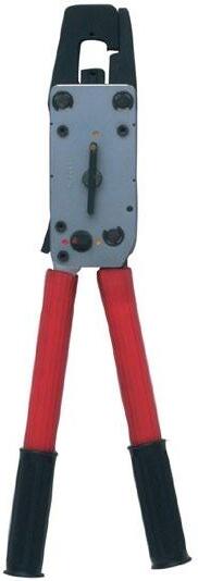
Crimp geometries
Charger: 230VAC
Delivered with 2 batteries
Charger: 115VAC
Without Battery/ Charger
Mechanical hand-held tool for crimping Cu-terminals, type KR/KS 10 mm², KRF/KSF 16-95 mm², KRD/KSD 16-120 mm², KRT/KST 10-120 mm², Al-terminals 16-25 mm² (-35 solid), and C-sleeves 6/6-50/50 mm², DIN 46235 10-95 mm².
Properties:
• opening for easy die changes and for quick removal after jointing
• crimp force approx. 57 kN
• advanced force ratio for lowest handle force
• easy to work with in confined spaces
• only four die pairs are required to crimp 10-95 mm² Cu
• quick feed function
• delivered in a metal box
mm² (Cu) mm² (Solid Al) Name Crimp geometries
10-95 35 T2600 Punch, Hexagonal, Oval 1,9 445 185 52
10-120 35 T2600B Punch, Hexagonal, Oval 4,12 445 185 52 10-120 35 T2600C Punch, Hexagonal, Oval 4,12 445 185 52
For joints on overhead lines AlMgSi (Super B) and Al59, hexagonal crimping. Supplied in pairs.

Die pair TBNP 16-20.
mm²
Overhead line Name Number of crimps Net weight (kg) Note
31 - 99
TBNP16-20 2x5, 2x10 0,135
Used for AlMgSl and FeAl, LFS31, LFS62 and LFS99

Crimp geometries
Tested and certified crimp head for crimping Cu-terminals, type KR/KRT 10 mm², KS/KST 10 mm², KRF/KRD/KRT 16-400 mm², KSF/KSD/KST 16-400 mm², Al-terminals 16-400 mm² (-240 solid), DIN 46235 10-300 mm², C sleeves up to 240 mm² total area (C95-120). Used in combination with foot pump P4000 or the electrically powered pump PS710 (battery powered version of PS710E is also available).
Properties:
• working pressure 63 MPa (630 bar)
• crimp force 130 kN (13 tonnes)
• versatile and easy-to-use steel crimp head

Crimp geometries
Tested and certified hydraulic hand-held tool for crimping Cu-terminals, type KR/KRT 10 mm², KS/KST 10 mm², KRF/KRD/KRT 16-400 mm², KSF/KSD/KST 16-400 mm², Al terminals 16-400 mm² (-240 solid), DIN 46235 10-300 mm², C-sleeves up to 240 mm² total area (C95-120).
Properties:
• fast forward feeding
• crimp force 130 kN (13 tonnes)
• requires low handle force, approx 245 N at max force
• the fork can rotate 180°
Tested and certified battery-powered crimp gun for contact crimping Cu-terminals, type KR/KRT 10 mm², KS/KST 10 mm², KRF/KRD/KRT 16-400 mm², KSF/KSD/KST 16-400 mm², Al-terminals 16-400 mm² (-240 solid), DIN 46235 10-300 mm², C sleeves up to 240 mm² total area (C95-120).
Properties:
• ergonomic design ensures optimum balance in the user’s hand
• crimp monitoring with warning light and signal when the correct pressure/full crimp is not achieved
• LED work lighting
• possibility of documentation of each crimp for unique service control
• crimp force 124 kN (13 tonnes)
• crimps/charging: 60-120 depending on size and temperature
• crimp time: 4-12s depending on size
• usage temperature -20°C to +40°C
• Li-Ion Makita, 5.0 Ah, 18V
• charger Li-Ion Makita, charging time 22 min 110-240VAC 50-60Hz
• DUAL: 10 - 300 mm²
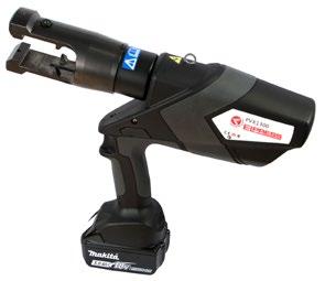
(Cu)

10-400 16-400 16-240 PVX1300 Punch, Dual, Hexagonal, Oval

Delivered in standard case 10-400 16-400 16-240 PVX1300DB Punch, Dual, Hexagonal, Oval
16-400 16-240 PVX1300-ADV Punch, Dual, Hexagonal,
10-400 16-400 16-240 PVX1300DB-ADV Punch, Dual, Hexagonal, Oval
10-400 16-400 16-240 PVX1300-WOBCADV Punch, Dual, Hexagonal, Oval
10-300 16-400 16-240 PVX1300-US Punch, Dual, Hexagonal, Oval
10-300 16-400 16-240 PVX1300DB-US Punch, Dual, Hexagonal, Oval
10-400 16-400 16-240 PVX1300-WOBC Punch, Dual, Hexagonal, Oval
Delivered in case
Delivered with 2 batteries and case adv.
Delivered in case adv. and without Battery/ Charger
and US-charger
Delivered with 2 batteries and US-charger
Delivered without Battery/Charger
Supplied in pairs. Hexagonal crimping. Use inner die holder V1316, and outer die holder V1318.

Outer die holder V1318, BNP dies, inner die holder V1316.
mm²
Overhead line Name Number of crimps Net weight (kg) Die holder required Note
31-62 B16NP 2x5 0,118 Yes
99 B20NP 2x5 0,126 Yes
157 13B26 2x16 0,420 No
241 13B32 2x16 0,408 No
Supplied in pairs. BxxFE dies are used for steel sleeves and BxxNP dies are used for Al-sleeves. Use inner die holder V1316 and outer die holder V1318

Die pair B16NP
mm² Die Fe Die Al Number of crimps
62 B6FE B16NP 2x5
99 B8FE B20NP 2x5
AlMgSi 31-62 mm², FeAL: 62 mm², ALUS 50 mm²
AlMgSi 99 mm², FeAL: 99 mm²
Overhead line: 157 mm² (2x16 crimps)
Overhead line: 241 mm² (2x16 crimps)

Crimp geometries
Tested and certified crimp head for crimping Cu-terminals, type KR/KRT 10 mm², KS/ KST 10 mm², KRF/KRD/KRT 16-800 mm², KSF/KSD/KST 16-800 mm², Al-terminals 16-630 mm² (-300 solid), C sleeves 6/6-300/300 mm². Used in combination with foot pump P4000 or the electrically powered pump PS710 (battery powered version of PS710E is also available).
Properties:
• working pressure 63 MPa (630 bar)
• crimp force 250kN (25 tonnes)
• large crimp area, 10-800 mm²
Supplied in pairs. For joints on overhead lines AlMgSi (Super B) and Al59, hexagonal crimping. Use inner die holder V2506 and outer die holder V2508
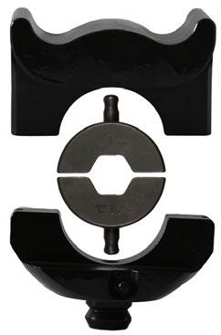
Die holder V2508, BNP dies, die holder V2506. mm²
Supplied in pairs. BxxFE dies are used for steel sleeves and BxxNP dies are used for Al-sleeves. Use inner die holder V2506 and outer die holder V2508

mm² Die Fe Die Al
62 B6FE B16NP 2x5
99 B8FE B20NP 2x5

Additional storage box for LV1300B and LV250, with space for accessories to crimp Elpress Al-terminals.
Properties:
• material plywood
• interior material polyethylene
• solid, moulded interior

Storage box with space for tool V250 and all necessary accessories to crimp Elpress Cu-terminals.
Properties:
• material plywood
• interior material polyethylene
• solid, moulded interior
Shearbolt terminals up to 36 kV
Elpress shearbolt terminals are available as through connectors and terminals for:
• stranded and solid Al and Cu cables
• round cross section 10 to 630 mm²
• sector cross section 16 to 240 mm²
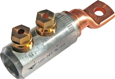
SL240N-12
The screws used are made of brass, that has the advantage of providing a lower friction compared to aluminium or steel screws. This makes it easier for the user to perform the installation. Installation tools can be a socket wrench or an impact wrench with torque force >100 Nm. We recommend that the fitter uses a counterhold tool to secure the shearbolt terminal more easily when tightening the screws.
Handles multiple area steps
The advantages of shearbolt terminals are that installation can be done easily without any heavy special tools and that they can manage several area steps in the same through connector/terminal, for example 10-50 mm². The user gets a reduced range of products and a flexible solution.
Shearbolt terminals are made of hardened aluminium with an alloy that allows both copper and aluminium cable to be joined, while preventing the occurence of galvanic corrosion. To reduce the number of terminal variants, screw terminals are supplied with reduction washers that allow the use of two different bolt sizes.
Washers are always needed for connecting terminals with screw joints to busbars.
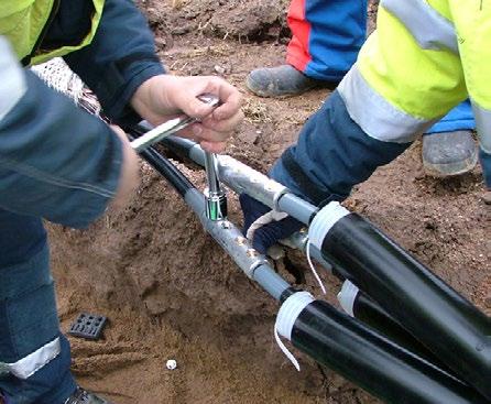
Use a socket wrench to tighten the screws. It is also possible to use an impact wrench.
On the SC50R50S through connector, the screws are threaded into the sleeve and can handle all their cable areas on one thread length. SC50R50S is also suitable as a screen connector for 10-35 mm² Cu/Al.
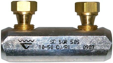
Elpress marking of shearbolt terminals shows logo, product name, cable area (for stranded and solid conductors) and shearbolt installation order. The terminal palm is marked with screw size M-thread for bolted joints.
Cat. no. SL70R70S-10-12
SL = Shearbolt terminal
70R = max 70 mm² round conductor
70S = max 70 mm² sector conductor
10-12 = screw size 10 and 12 M thread
Cat. no. SC50R50S
SC = Shearbolt connector
50R = max 50 mm² round conductor
50S = max 50 mm² sector conductor
The following apply for bright galvanized type nuts and screws, with strength class 8.8, used for connecting terminals with Cu and Al palms:
• Always use a torque wrench to be certain the right torque is achieved. Make sure it is calibrated at regular intervals according to the supplier’s instructions.
• Use the recommended torque according to the screw manufacturer’s instructions.
• Always use a hard flat washer to reduce friction against the connection surface and the edge pressure, hardness min HB200.
• Install as illustrated.

Recommended tightening torque for wet lubricated screws and nuts of bright galvanized zinc type with strength class 8.8 and coarse threaded (normal thread), used with corresponding washer for connection of terminals with Cu- and Al palm. See table in Chapter 12.
Properties:
• screw material: brass, for minimum friction
• partition
• pre-assembled shear-off screws for easy handling
• voltage range: 1 kV
• meets the requirements of standard IEC 61238-1
• PEN is a filler piece for use when connecting the cable’s copper screen
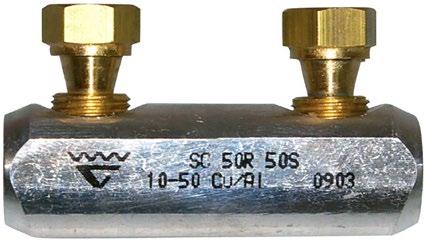

Through connector SC50R50S with threaded screws.
s = strip length
Properties:
• screw material: brass, for minimum friction
• partition
• reversible shear-off screws
• voltage range: 1 kV to 36 kV
• meets the requirements of standard IEC 61238-1
• PEN is a filler piece for use when connecting the cable’s copper screen
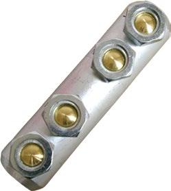
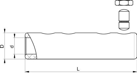

s = strip length
To splice the copper screen around the conductors, a filler piece is required that is placed between the screw and the screen. To select the correct filler piece, see table. Requires 2 filler pieces per splice.
Name Screen conductor Note
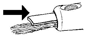
SC95N/PEN 16-57* *16-50 mm² (SC95N) / 16-57 mm² (SC95R95S)
SC150N/PEN 21-95
SC240/PEN 29-146
Properties:
• screw material: brass for minimum friction
• pre-assembled shear-off screws for easy handling
• voltage range: 1 kV for SL50N-10-12, SL95N-10-12 and SL240N-10-12, 1-36 kV for the others
• meets the requirements of standard IEC 61238-1
• the terminals are of the bimetallic type
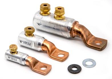
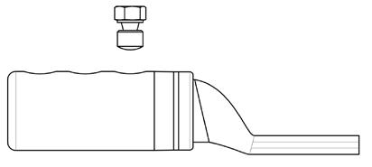
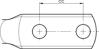

t = palm thickness, s = strip length
Properties:
• screw material: brass for minimum friction
• reversible shear-off screws
• voltage range: 1 kV to 36 kV
• meets the requirements of standard IEC 61238-1
• the terminals are of the bimetallic type for best functionality
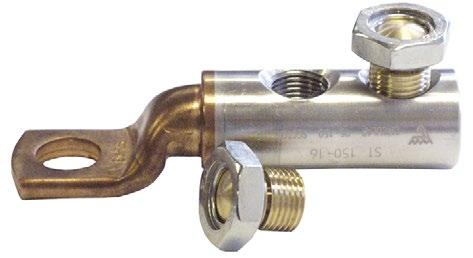
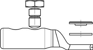

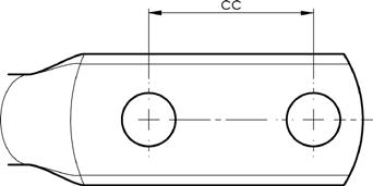
t = palm thickness, s = strip length
Screw clamps for earthing applications. Enables branching of reinforcing bars with a stranded earth line in Cu or Fe.
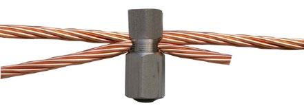
Name Pcs/pack
SBC50 1
Counterhold tool for stable and safe installation of shearbolt terminals. Tools are made from durable material and are easily adjustable for terminals up to 400 mm².

Name Pcs/pack
ISL2201 1
Complete kits - click & heat
Complete kits for easy splicing of 1 kV plastic insulated 3-, 4- and 5-conductors.
The kit consists of shearbolt connectors with partition and heat shrink insulation. The connection between the cable and the through connector is done by means of screws in a shearbolt terminal. Insulation is done with suitable heat shrink insulation.
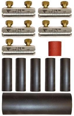
Kit for 5-conductor
This is how it works:
• The cable conductor is spliced with a shearbolt connector fitted with torque screws that shear when the correct torque is reached.
• The different phase conductors are insulated with heat shrink insulation of polyolefin.
• The insulation is internally coated with adhesive that melts when heated
• When the adhesive is pressed forward out of the shrunken body, the installation is finished and the joint becomes entirely watertight.
• Sector-shaped conductors do not need to be rounded.
• With the attached filler piece you can easily splice a 3+1 cable to a 4G cable.
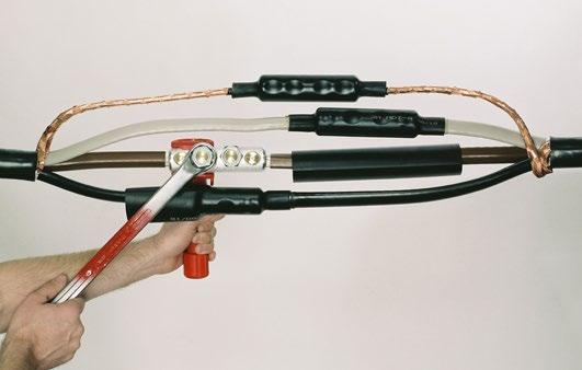
Conductors are spliced using shearbolt connectors Tighten the screw using a socket wrench, until it shears in the cut-off groove.
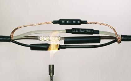
Shrinkage of the insulation is achieved by using heat.
Kit for splicing 3-, 4- and 5-conductor cable according to IEC 60228. For both Cu/Al solid and stranded conductors.
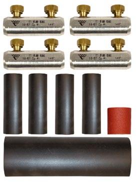
10-50 16-50
KSC50N-1-4HS 1 outer jacket, 4 SC50N, 4 inner tubes and abrasive cloth. 10-50 16-50
KSC50N-1-5HS 1 outer jacket, 5 SC50N, 5 inner tubes and abrasive cloth. 35-95 50-95
KSC95N-1-4HS 1 outer jacket, 4 SC95N, 4 inner tubes and abrasive cloth. 35-95 50-95
KSC95N-1-5HS 1 outer jacket, 4 SC95N, 5 inner tubes and abrasive cloth. 70-150 70-150
KSC150N-1-4HS 1 outer jacket, 4 SC150N, 4 inner tubes and abrasive cloth. 70-150 70-150
KSC150N-1-5HS 1 outer jacket, 5 SC150N, 5 inner tubes and abrasive cloth. 95-240 95-240
KSC240N-1-5HS 1 outer jacket, 5 SC240N, 5 inner tubes and abrasive cloth.
KSC240N-1-4HS 1 outer jacket, 4 SC240N, 4 inner tubes and abrasive cloth. 95-240 95-240
Connector kit for splicing 1 kV plastic insulated 4G or 5G cable of stranded Al conductor 16-25 mm², and for splicing or transitioning to Cu 10-16 mm² class 1, 2, 5 or 6.
The kit consists of heat shrink insulation and joint sleeves, which can take a wide range of cable. The concept includes a through connector for transition between the copper cable and the aluminium cable. Used to splice Al cable for lighting and services.
You only need one tool to crimp through connectors and you can choose between a hand tool or a crimp die with an open matrix that fits in Elpress 6-tonne tool systems.
This is how it works:
• The conductors are spliced with sleeves AS1625, AKS1625-1016 or KSF16.
• Use Elpress pliers EW EW1025, or TB die pair TBKA9-11.5 with 600 system.
• The inner and outer tubes of the insulation are dimensioned which means they can be easily applied and then shrunk using heat.
• The length of insulation is adapted to safely cover the cable’s primary and sheath insulation
• The insulation is thick-walled and coated with a lot of adhesive that makes the joint waterproof and robust in the face of external influences.
• Meets the requirements in SS-EN 50393, EBR KJ 24:89 The through connectors are tested and approved according to EN 61238-1.


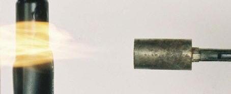
Kit for splicing 4- or 5G cable of stranded Al-conductor 16-25 mm² according to IEC60228, and for splicing or transitioning to Cu 10-16 mm² class 1, 2, 5 or 6. Meets the requirements in SS-EN 50393, EBR KJ 24:89

16-25 10-16 KHS-AKS1025-4 V600, EW1025 4
Contents: 1 outer jacket, 4 AKS16-25-1016, 4 inner tubes and abrasive cloth.
16-25 10-16 KHS-AKS1025-5 V600, EW1025 5 Contents: 1 outer jacket, 5 AKS16-25-1016, 5 inner tubes and abrasive cloth.
16-25 KHS-AS1625-4 V600, EW1025 4
Contents: 1 outer jacket, 4 AS1625, 4 inner tubes and abrasive cloth. 16-25 KHS-AS1625-5 V600, EW1025 5 Contents: 1 outer jacket, 5 AS1625, 5 inner tubes and abrasive cloth.
Joint kit for splicing Al conductors 50-240 mm². MultiCrimp Punch crimping for low voltage applications (1 kV) according to IEC 60228, with the 1300-system.
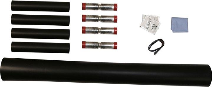
To strip insulation from cable there are, for example, the Embla, Tor and Oden ranges, that strip from approx. 0.02 mm² up to approx.Ø 40 mm cable. The tools are characterised by high precision, ergonomic adaptation, user friendliness and reliability.
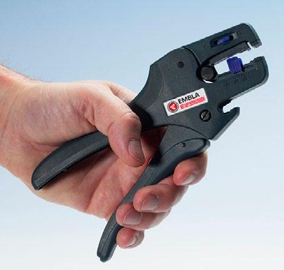
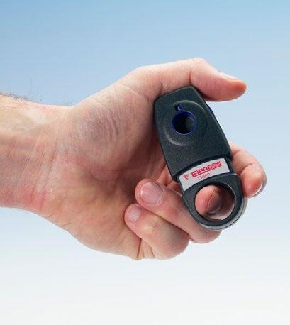
Tools are available in several variants for cutting Cu and Al cable up to approx. Ø 85 mm. In addition to the simplest mechanical tools that cut cable up to Ø 20 mm, there is a wide range of hydraulic tools for cutting cable up to approx. Ø 85 mm.
The size of the conductor that the tools can handle mainly depends on the type of conductor to cut; whether it is a low or medium voltage cable and whether it is, for example, a solid Class 1, flexible Class 5 or stranded Class 2 conductor. The hardness of the conductor’s material also affects the results. For example, the PKL54C is capable of cutting type Cu FKKJ 4 x 95 mm² low voltage cable or Al AKKJ 4 x 240 mm² or medium voltage cable type Al AXLJ 3 x 150 mm². The insulation takes some space on the medium voltage cable, which is why it can be restrictive.
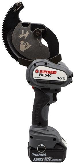
For preparation of medium voltage cables, 12-24 kV, and removal of conducting layers and PEX insolation, tools FBS1722 and FBS1723 are available.
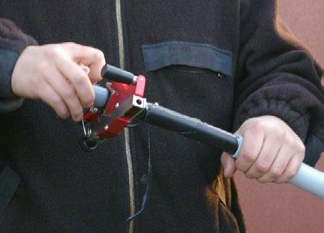
Properties:
• cutting capacity (EMBLA S, standard cassette): - single core conductor 1.5 mm² (AWG 16), - multi-stranded conductor 10 mm² (AWG 8)
• Versatility: The simplicity and ability to change the stripping cassettes allow stripping of most modern insulation materials. The operating range is the widest found in this type of tool.
• Precision: Fine-adjustment allows stripping of even thin insulation without conductor damage. When stripping is complete, the stripping blades are opened and kept open during the blade return so that the cable can be removed from the tool, easily and without scratches.
• Ergonomics: Specially formulated shape, soft rubber inserts in the fixed handle, low friction, optimized handle width, angled head and low weight ensures comfortable work with the lowest load.
• Long life: Stripping cassettes and cutting blades can be replaced for long tool life.
• Reliable: Tested for over 150,000 cycles. Made of high strength plastic with double strength compared to standard PA6 (nylon).
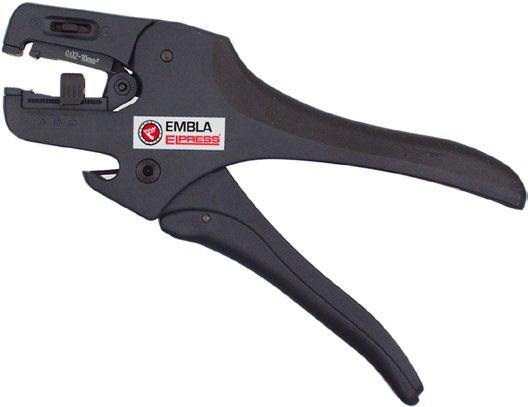
Stripping and cutting tools.
Embla is available in 3 versions:
EMBLA S,
• with stripping blade, straight blades for PVC insulations 0.02-10 mm² (AWG 34-8)
EMBLA V,
• with stripping blade, V-shaped blades, for harder insulations 0.1-4 mm² (AWG 28-12) EMBLA 16,
• with stripping blade, oval-shaped blade, for 4-16 mm² (AWG 12-5)
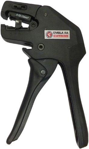
Stripping and cutting tools with right-angled handles. mm² AWG
0,02-10 34-8
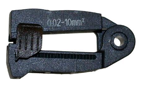
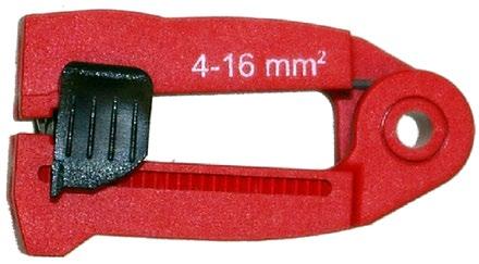
EMBLA and EMBLA RA can be supplemented with the following stripping cassettes for different types of cable sizes and insulation. The cassettes can be quickly and easily changed.
EMBLA SP S
• with stripping blade, straight blades, for PVC insulation 0.02-10 mm² (AWG 34-8)
EMBLA SP V
• with stripping blade, V-shaped blade, for harder insulation 0.1-4 mm² (AWG 28-12)
EMBLA SP 16
• with stripping blade, oval-shaped blade, for 4-16 mm² (AWG 12-5)
mm² AWG Name Net weight (kg)
0,02-10 34-8
0,1-4 28-12
EMBLA SP S-CASSETTE 0,002
EMBLA SP V-CASSETTE 0,002 4-16 12-6
EMBLA SP 16-CASSETTE 0,002

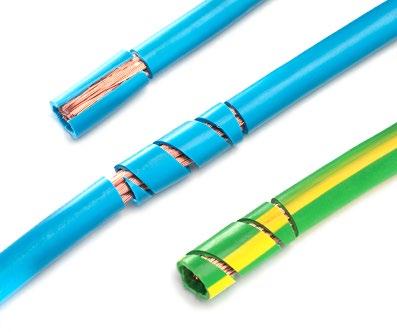
Three stripping functions.

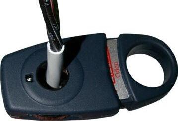
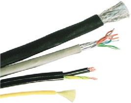
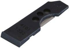
Cable stripping tool for cable insulation Ø 4.5 - 40 mm
Properties:
• two interchangeable hooks for different cable diameters
• locked positions for cross, longitudinal and spiral sections
• stripping: cable diameters 4.5 - 40 mm, insulation thicknesses up to 4.5 mm
Dimensions: Small hook / (large hook)
Stripping tool to strip insulation from cables Ø 2.5 - 11 mm. Used for signal, telephone, audio, instrument, data cable and similar.
Properties:
• fine-adjustment and adjustment are performed with a nine-position setting wheel
• stripping: cables Ø 2.5-11 mm, up to 1.0 mm thick outer layers
• flexible: strips or removes the outer layer on most multi-conductors and optical cables up to Ø 11 mm
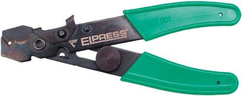
Stripping and cutting tool for cutting and stripping conductors 0.5 - 6 mm².
Properties:
• material: high-quality steel
• cuts 0.5-6 mm² (20-10 AWG)
• strips 0.5-6 mm² (20-10 AWG)
• light and versatile
• lockable setting

Cable cutter for cutting cable up to approx. Ø 10 mm.
Properties:
• cuts Cu and Al cable up to approx. Ø 10 mm
• not intended for cutting steel
• small and manageable
• tempered forged steel cutting blade
• design of the blade inserts provides a clean cut surface Max ø conductor Name Net

Cable cutter for cutting cable up to approx. Ø 20 mm².
Properties:
• cuts Cu and Al cable up to approx. Ø 20 mm
• not intended for cutting steel
• sturdy and comfortable handle grip
• tempered forged steel cutting blade
• design of the blade inserts provides a clean cut surface Max ø conductor Name Net weight (kg)
20 CT20 0,471 240 78 21

Cable cutter for cutting cable up to approx. Ø 15 mm.
Properties:
• cuts multi-stranded Cu and Al conductors.
• not intended for cutting steel
• small and manageable
• high quality, professional tool
• design of the blade inserts provides a clean cut surface
• minimal power requirement
Not for steel wire and wire reinforced cable.
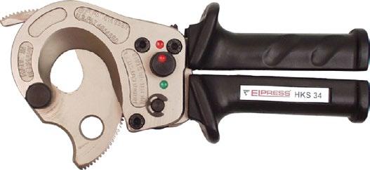
Cable cutter for cutting cable up to approx. Ø 34 mm.
Properties:
• cuts normal types of Cu and Al cable
• cuts alloyed AC overhead line and BLX up to a diameter of 241 mm² (not FeAl)
• comes with durable textile bag
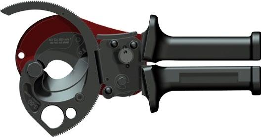
Cable cutter for cutting cable up to approx. Ø 50 mm.
Cutting tool for steel and Cu/Al cable with interchangeable blades. HKS50 is supplied with universal blade UFE1 for Al/Cu, FeAl line, flexible steel line and anchoring cables.
Comes in a sturdy textile bag with instructions for use and cleaning tool for threads.
Properties:
• scissor-motion for the best cut surface on the cut cable
• single-handed operation facilitates installation
• reliable and proven ratchet function
• move blades easily and quickly by releasing two screws
• clearly marked usage area on the blades Max ø
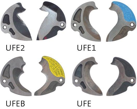
50 UFE2 0,13 For Cu/Al, flex. steel line, INOX, FeAl line, screw, anchoring cable, piano wire and solid Cu overhead line.
50 UFE1 0,104 For Cu/Al, flex. steel line, INOX, FeAl line, screw, anchoring cable and solid Cu overhead line.
30 UFEB 0,111 For Cu/Al, flex, steel line, FeAl line and mainly used for cutting data/signal cable.
50 UFE 0,104 For Cu/Al cable, clean cut surface and adapted for most flexible cables. Not suitable for cutting steel.
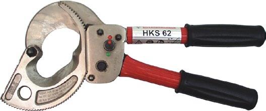
Cable cutter for cutting cable up to approx. Ø 62 mm.
Properties:
• cuts normal types of Cu and Al cable
• cuts alloyed AC overhead line and BLX up to a diameter of 241 mm² (not FeAl)
• comes with durable textile bag

Cable cutters for cutting cable up to approx. Ø 80 mm.
Properties:
• cuts normal types of Cu and Al cable
• comes with durable textile bag
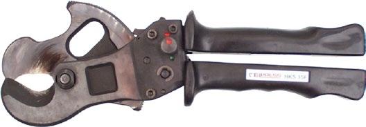
Cable cutters for cutting cable up to approx. Ø 35 mm.
Properties:
• cable cutter
• cuts normal types of Cu and Al cable
• comes with durable textile bag

Cable cutters for cutting cable up to approx. Ø 60 mm.
Properties:
• cable cutter
• cuts normal types of Cu and Al cable
• comes with durable textile bag
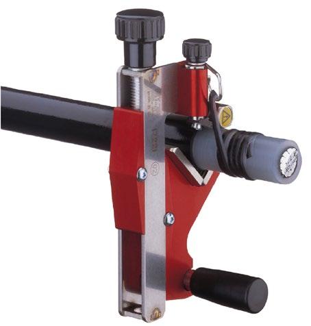
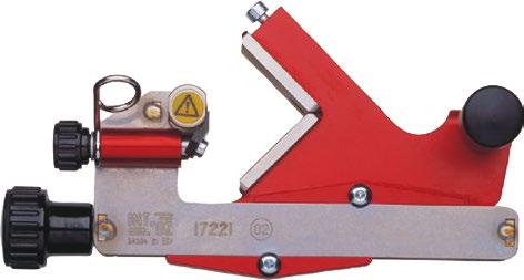

FBS1722 comes with box, silicone paste and instructions for use.
Stripping tool for fixed, outer conductive layers on PEX cables.
Properties:
• FBS1722 contains the stripping tool, 100 g silicone paste and instructions for use, in a padded plastic box
• insulation can be stripped from Ø 10 to Ø 50 mm, which corresponds to up to 800 mm² at 12 kV, 630 mm² at 24 kV and 500 mm² at 36 kV
• the depth of cut is set between 0 and 1.2 mm in 0.1 mm increments using a knob
• stripping can be done up to 25 mm from the edge of the screening and the PEX surface becomes very even
• the blade is hardened, min HRC 55, and specially ground, as well as very easy to replace
Spare parts for the FBS1722 stripping tool. RS = spare blade and SP = silicone paste.
Name Net weight (kg)
FBS1722RS 0,006
FBS1722SP 0,115
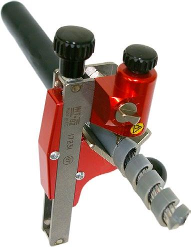
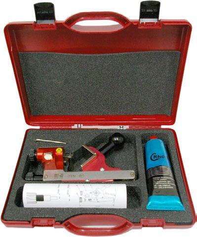
FBS1723 comes with box, silicone paste and instructions for use.
Stripping tool for stripping PEX insulation on medium voltage cable.
Properties:
• FBS1723 contains the stripping tool, 100 g silicone paste and instructions for use in a padded plastic box
• the tool is easy to use - rotate the tool with the handle
• stripping can be done from Ø 15 to 52 mmm which corresponds to cable 12 kV 50-1000 mm², 24 kV 25-1000 mm², 36 kV up to 630 mm² and 52 kV up to 500 mm²
• depth of the blade can be adjusted from 0 to 15 mm
• unlimited stripping length
• the cutting blade is available as a spare part
• adjustable feed in 5 positions, the blade is hardened, min HRC 55, and specially ground and very easy to replace
Spare parts for the FBS1723 stripping tool. RS = spare blade and SP = silicone paste.
Name Net weight (kg)
FBS1723RS 0,001
FBS1722SP 0,115

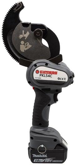
Battery powered cutting tool PKL54C.
Electric cable cutter for cutting Cu and Al cable, max. cutting diameter
Properties:
• not intended for cutting steel
• comes in a bag with Li-ion battery, 14.4 V, as well as charger
mm.
• tool performs a scissor motion when cutting that provides an optimal cut surface
• built-in fuse as a surge protector
• CE-marked
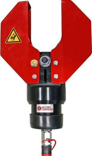
Hydraulic cable cutting head for copper and aluminum cable.
Properties:
• cuts up to 4 x 150 mm² Cu conductor and ø 85 mm Al, paper and plastic insulated conductors (there may be restrictions depending on the conductor’s design and materials)
• cuts steel-reinforced cables, but not steel wire-reinforced cables
• used with foot pump P4000 or electrically powered pump PS710
• supplied in plywood box
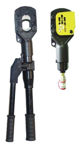



A series of cable cutters covering almost all needs when cutting power cables and lines. The cutter heads (KL) are operated with one of Elpress’ pumps, e.g. foot pump P4000 or pump PS710.Not for steel wire and wire reinforced cable.
Elpress systems for deep earthing have many advantages:
• The ground line has no joints – no risk of contact failure.
• Tip and leading rod are manufactured for a large area range; 16 - 95 mm².
• Can be used for different types of line e.g. soft or hard copper, galvanized or stainless steel.
• When copper line is used, the extension rods act as sacrificial anodes and provide good protection against corrosion.
• Full control over the line and tip is maintained and it is possible to continuously measure the earthing resistance.
• Thanks to the few components of the system, driving is both uncomplicated and reliable.
• The system has a low overall weight compared to other systems.
• The overall cost of a complete earth connection will be lower than that made in a conventional manner.
• Rod length 800 mm for best ergonomics.
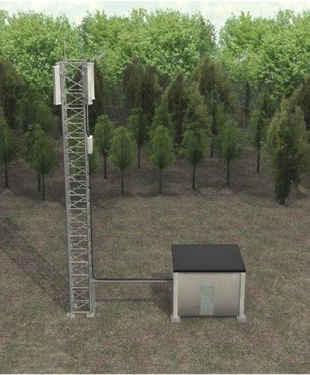
Elpress’ approach is an earthing system without joints. The electrode consists of a copper line that is driven down by a system consisting of 0.8 m long steel rods. A hardened steel tip paves the way for the ground line that is inserted into the steel tip and clamped by the leading rod. For every 0.8 m length of driven line and rod, an extension rod is pushed into the preceding rod. Because the earthing resistance can be continually measured at the other end of the line, one can stop driving when a suitable value is reached and the last extension rod is then withdrawn.
Driving takes place with the aid of a power hammer with an adapted driving sleeve or a sledge hammer and impact sleeve FS62C.
Elpress deep-earthing system consists of steel rods and a copper line. The steel rods act as sacrificial anodes with relatively high corrosion current against the copper electrode (cathode). This combination of metal both stabilises and equalises its surroundings. If a lead sheathed cable is located in the soil a few metres from the earth connection, the corrosion current from the lead anode to the Fe+Cu earth connection is 40% less than the value of an earth connection without FE rods. In other words, the lead sheath has a theoretical service life of almost double.
Experiments have shown that after a few months, the corrosion current drops to virtually zero. The explanation is that a special layer – the polarization layer – is formed next to the electrode. The current is thereby reduced and thus also the corrosion. The amount of the reduction depends on the properties of the soil. An AC load should theoretically counteract the corrosion. This means that the practical service life is often longer than the theoretical.
Elpress systems consist of the following 5 parts:
• hardened steel tip
• leading rod
• extension rod
• driving sleeve/impact sleeve
• earth line (not supplied by Elpress)
This feature is simple
• the earth line is inserted into the hardened steel tip and clamped by the leading rod.
• the extension rods are fitted with a guide pin, which during work is pushed into the preceding rod.
• earthing resistance can be measured continuously. When the appropriate value is reached, driving is interrupted and the last extension tube is withdrawn (and can therefore be reused).
Practical advice:
1. Plan the earth connection. What are the soil conditions?
Normal and loose soil - steel pipe Ø 17 mm is sufficient. Hard and rocky soil- steel rod Ø 21 mm (type HD) should be used. Is a parallel earth connection possible?
2. Determine the soil resistivity. Based on that and the maximum earthing resistance it can be estimated how much line is needed.
3. Start the driving by locking the line into the hardened tip with the leading rod. 16 mm² line should be folded double before the tip is attached. In loose soil, a sledgehammer and impact stud is sufficient. In heavier soil/at greater depth, a power hammer should be used. NOTE: Do not rotate the driving sleeve during the work.
4. Make sure that the line maintains the same speed down into the soil as the rod. If it does not, there are the following possibilities:
- more rods than line required; the rod may have been bent and then runs parallel to the surface of the soil and the line does not follow the pipe through the ground.
- the rod continues and the line stops; the line has come loose and can be pulled up or the tip has folded.
- both stop; stone or rock has been found. If the stone does not shatter after about 10 seconds, you must start over.
In the event of interrupted driving, start again at a distance at least 1.5 times the line length already driven down.
5. Preferably measure the earthing resistance continuously while driving down the earth line. Arrange a parallel earth connection if necessary. Splicing and branching of the earth line is contact crimped by means of Elpress through connectors or branching sleeves and tools.

Elpress deep-earthing system FS consists of 3 parts. Tip (FS1x), leading rod (FS2x) and extension rod (FS3x).


Tip, with hardened steel furthest out. Fits FS21 and allows the use of different types of earth line.
Steel leading rod, equipped with a grooved notch to lock the earth line effectively. For loose and normal soil conditions.
ø
Steel extension rod, HD, equipped with a guide pin that fits inside the preceding rod. For loose and normal soil conditions. ø
Elpress deep-earthing system with thicker rods for tougher soil conditions FSHD (HD: ”Heavy Duty”) consists of 3 parts. Tip (FSHD1x), leading rod (FSHD2x) and extension rod (FSHD3x).

Hardened steel tip intended for hard and rocky ground. Used in conjunction with leading rod FSHD23.


Steel leading rod, equipped with a grooved notch to secure the earth line effectively. Designed for hard and rocky ground.
ø Name Net weight (kg) Length Pcs/pack
Steel extension rod, HD, equipped with a guide pin that fits inside the preceding rod. Robust rod intended for hard and rocky ground. ø

Pull handle with grip-friendly design that facilitates withdrawal and allows reuse of the last extension rod FS3x/FSHD3x. ø
Impact sleeve used when driving using a sledgehammer, or similar, to prevent deformation of the rod end. Specially designed for use with FS21 or FS31 rods. Name
Impact stud used when driving using a sledgehammer, and similar, to prevent deformation of the rod end.
Impact sleeve used when driving using a sledgehammer, or similar, to prevent deformation of the rod end. Specially designed for use with FSHD23/FSHD31 rods.
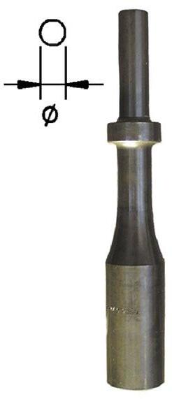
• specially designed for use with the FS21 and FS31 rods
• protects the end of the rod from deformation when driving with a power hammer
• for FS-type rods with an external diameter of 17 mm
• marked with the catalogue number
Name Tool
FS71C BBD 12 TS, BHB 14
FS72C BBD 12 T-01, Cobra 148/248, Pico 20, RH 571 5L/5LS, RH 658 5L/5LS, BHB 25
FS73C TEX 23E, TEX 25E
FS81C TE 52, TE 72, TE 92
FS83C USH27
FS85C BHF 25, BHF 30S
FS88C TE905/TE805
FS81D SDSMax Syst.
FS74C TEX 11-DCS, TEX-11-DKS, BR 37, BR 45, DR 19
FS77C TEX 31/31s, TEX41/41s, BR 67 UK BR 87 UK
with
mm outer diameter
version also available for rods with 21 mm outer diameter
An earth connection is a conductor placed in the soil, with the aim of diverting electrical current from an installation connected to the earth connection and into the surrounding soil.
A customer who buys power takes earthing for granted. This is despite the fact that the use of power without, or with poor, earthing incurs great risks. All power suppliers must have approved earth connections at their installations. This means that voltage surges that can occur for various reasons are led into the ground so that they do not cause damage. Earthing thus functions as, among other things, personal protection, property protection, signal transfer protection, lightning protection and the like.
An approved earthing should have: (1) low electrical resistance, (2) ability to conduct voltage stably (despite weather changes) and (3) long service life, i.e. good resistance to corrosion.
Soil conditions or external conditions?
The importance of the soil as a conductor of electric current is great. The technical specifications and requirements for earthing demonstrate the advantages of deep-earth connections, both as a technical and economic solution, in relation to surface-earth connections.
Current conduction occurs in the soil through electrolytic processes, known as ionic conduction. Solid particles such as gravel are not usually conductive.
The electrical conductivity of the soil therefore mainly depends on the proportion of saline water bound by capillary forces and osmotic pressure in the pores between grains of sand and in hygroscopic humus particles (e.g.clay).
The water in deeper lying ground layers usually has a higher salinity than the water in the surface layer. The higher the moisture content of the soil, the better the conductivity. Soil humidity normally varies between 5-40%. At variations below 14-18%, conductivity deteriorates significantly.
Cold (frost) significantly impairs the ground’s conductivity. It is of great importance that all this is taken into account for earth connections or earth connection systems.
Weather conditions - cold, heat, rain and wind - mainly affect the upper layer of the soil (0 - 1.5 m), which therefore exhibits the most powerful variations. The most efficient earthing is thus reached when the electrode is placed deep enough so as not to be affected by changes in soil humidity and temperature.
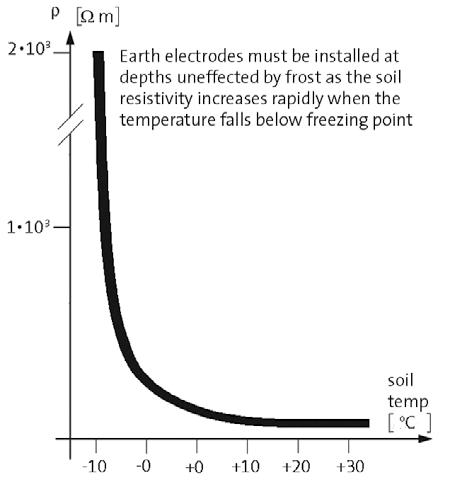


The electrical properties of the soil are quality declared by means of its resistivity, which is measured in Ωm (former unit Ωcm, 1 Ωm =100 Ωcm). Soil with good electrical conductivity thus has low resistivity: 10 - 100 Ωm.
For each case of different soil type, soil resistance must be measured and preferably during several seasons and in different weather conditions. In measurement today almost exclusively voltage compensated electronic resistance bridges are used (measurement method according to Wenner) with 4 connection contacts, 2 of which are for current electrodes and 2 for voltage probes.
The connectors are connected to 4 vertical metal tips that are driven down in a row about 0.3-0.5 m deep a metre apart. (See image)
If the instrument reading is R, the resistivity of the soil is calculated according to the following equation: p = 2 x a x R Ωm
In unlayered soil, resistivity is independent of the electrode distance a. By increasing distance a, the current penetrates deeper into the ground and the measured resistivity can fall or increase depending on the resistivity of the ground layer at 1 metre’s depth. When calculating approximate earthing resistance of the earth connection when the depth is l, the resistivity of the soil must be measured with electrode distance a ≈ 0.75 x l.
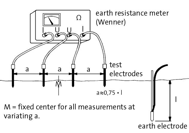
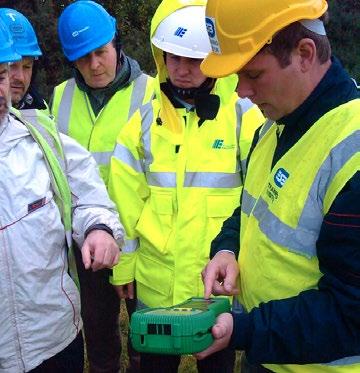
Due to the high resistance of the soil (109 x resistivity metal) at current bleed in the soil a strong electrical field is formed in the earth connection, which diminishes in strength with distance from the earth connection. At a certain distance, this field can be neglected (removed earth).
The earthing resistance of the earth connection is usually measured with the same type of instrument used to measure the resistance of the soil. However, this measurement requires only one voltage probe and a current electrode (auxiliary earth connection). The location of probes and electrodes varies between different measurement methods. The two methods that follow are a method of accurate technical measurement and a more practical, simplified method.
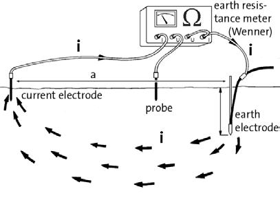
Measuring earthing resistance of the earth connection - Method 1
Method 1
(acc. to the lightning protection standard SS 4870110). This method has a measurement error of +/ - 2%.
The summary gives this method:
- The probe and auxiliary electrode are placed in a straight line from the earth connection to be measured as illustrated.
- If the ground is layered, measurement should be carried out in two directions. The largest value is used.
- The reliability of the measurement result depends on the location of the probe/ auxiliary electrode. Note the distance table below. These provide normally acceptable measurement accuracy.
earth connection - probe = 0.5a-0.6a earth connection - electrode = a
a ≥ 40 m if l ≤ 4 m
a ≥ 10 x l if l > 4 m
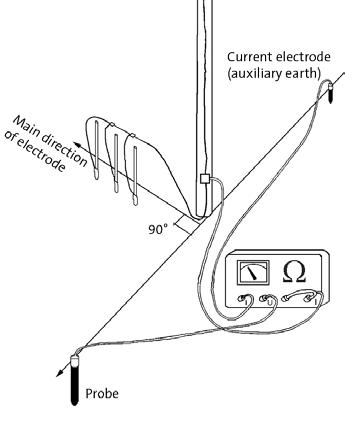
Measuring earthing resistance of the earth connection - Method 2.
Method 2
(acc. to EBR-standard U2:80)
This method normally has a measurement error of more than 2%, but practically is easier to perform than Method 1.
The summary gives this method:
- Probes and electrodes are placed as illustrated, 90° from the main direction of the earth connection.
- The position of the probe/electrode is equal when measuring both an individual earth connection as earth connection system, i.e. at least 80 m from the earth connection.
- Measurement of an earth connection is carried out with an open earth conductor clamp.
- Measurement of the resulting transition resistance on multiple earth connection systems is carried out with the clamp closed and with the measuring line connected on the top of the earth conductor clamp. With the help of the conductivity and the maximum earthing resistance, which is required by, among other things, the high current regulations, it is possible to estimate how much line may be needed according to the formula:
l = p / R
l = length in metres
p = soil resistance in ohmmeter
R = earthing resistance in ohms.
In the discussion of the advantage of deep-earth connections compared to surface-earth connections, it should be mentioned here that the earthing resistance of a horizontal surface-earth connection is twice that of a similar line length in a deep- earth connection, i.e.
R0 = 2 x p / l
Parallel connection
Parallel connection of several earth sockets is often necessary for practical reasons to achieve a sufficiently low value of earthing resistance during earthing. In order to limit reciprocal connection between individual earth connections, deep-earth connections shall be installed a distance apart of 1.5 times the depth of the earth connection l. Resulting earthing resistance:
Rres = k x Rm
where Rm is the mean of the resistance value of the earth connection and k a reduction factor, the value of which is obtained from the following table.
No. of parallel earth connections k for a = 1.5l
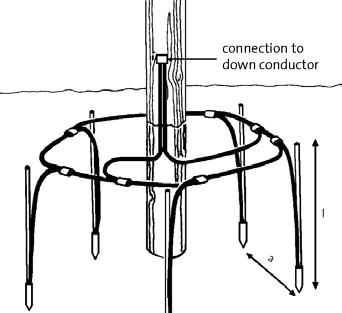
From economic aspects it can be pointed out that the diameter of the earth connection has a negligible role when calculating the earthing resistance in deep earthing. This means that when using Elpress deep-earthing systems with copper line, the cost will be lower than when using, for example, conventional systems. What is important in practice in terms of the cable diameter is what currents the system is dimensioned for and what rules and requirements apply.
Examples of applicable requirements: the lightning protection standard states Culine min 25 mm², EBR prescribes min. Cu-line 35 mm² for earth connections in overhead line networks and min. 50 mm² for earth connections in ground cable networks.
The service life of an earth connection depends on its resistance to corrosion (rust). The prerequisite for all types of corrosion is an electrolyte fluid that allows the transport of positive metal ions from anode to cathode. At the anode, metal atoms are dissolved in the electrolyte, forming free positive ions - oxidation- and at the cathode these ions are neutralized and deposited on the metal surface - reduction.
In galvanic corrosion caused by contact between two metals, the corrosion rate is proportional to the galvanic tension between the metals. A base metal has higher negative potential than a nobler metal and therefore forms the anode in a corrosion process.
There is also a clear correlation between the corrosion rate and ground resistance. The rate of corrosion depends on the composition of the soil. Influencing factors are the pH of the soil, temperature, oxygen content, moisture content and resistivity. These factors affect the corrosion current lk, which is directly proportional to the rate of corrosion. lk can be determined by direct measurement with an Ammeter or calculated, if the transition resistance Rö between the two electrodes is known, according to formula: lk = Ug / Rö
Ug = galvanic voltage
In some cases, Rö can be measured with a resistance bridge of the same type used to measure the earthing resistance of an earth connection. The rate of corrosion is often expressed in μm/year where 1 μm represents 1/1000 of 1 mm and denotes the thickness of the corroded away outer metal layer for 1 year. The table below indicates some practical values as guide values for different soil resistivity.
Resistivity Corrosion
p < 1 Ωm 100 μm/year
p < 1-10 Ωm 100-30 μm/year
p < 10-100 Ωm 30-4 μm/year
p > 100 Om negligible

There is a wide range of electrical terminals today, and it can be difficult to know if you have chosen the right solution for your installation.
A first step is to ensure that a system is chosen, consisting of terminal, tools and a standard conductor.
In order for this combination of material to be classified as a system, there must be common test documentation, a type test according to a standard relevant to the material.
There may also be a need to identify the correct terminal depending on the cable class. Cables are divided into different classes depending on their structure. With System Elpress you get a complete solution, KRF/KSF in combination with Dual can be combined with all Cu cable classes. Elpress systems for aluminium indented crimping are a robust solution that can be used with all types of Al cables.
Not choosing a system carries great risks. All terminals are designed with respect to a specific tool system. Small differences in dimensions of terminals and tools can lead to serious consequences, such as hot running or fire.
Elpress terminals have been developed over 60 years of continuous work to always meet the highest standards. Our terminals are designed to be able to operate at a continuous temperature of 90°C and to always be able to carry the same load that the relevant cable area can handle.
This means, among other things, that tubes for our KRF/KSF are dimensioned to be adapted to the cable’s conductivity. This type of terminal should be crimped with a hexagonal geometry that provides a symmetrical shape that distributes crimp force evenly and ensures that thin strands are not damaged shortening the lifetime of the connection.
Our aluminium terminals are designed according to the same criteria and requirements as mentioned above, and should be crimped with a punch tool that ensures that the aluminium insulating oxide layer is broken and that good points of contact are created between conductors and terminal.
Elpress terminal systems are designed to be used in conjunction with cables according to IEC 60228. This is an international standard used all over the world and describes the structure and conductivity of a cable (Ω/km) The norm divides cables into classes as shown below. Class
Another important aspect of a system is a knowledgeable and trained operator. Good and safe work requires knowledge of materials, regulations and the importance of using a system solution. We offer company-adapted training that includes both theoretical and practical parts.
Types of conductor
Cables in each class shall have mechanical and electrical properties that meet the requirements of the norm, which means that they can be used with System Elpress without special adaptation. In addition to the classification of conductors, the differences between cables are mainly in the design of the insulation.
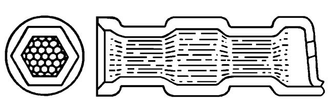
Hexagonal crimping.
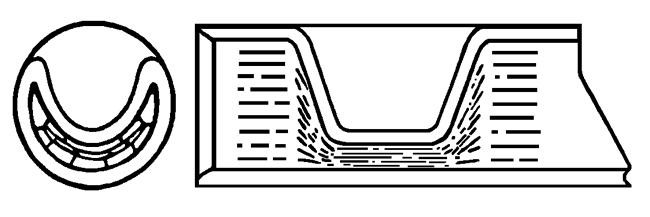
Indented crimping.
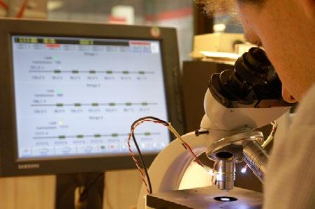
SEK Svensk Elstandard is appointed by the government to be responsible for all standardisation within the electrical area in Sweden.
The Standards are established mainly through international and European collaborations within the International Electrotechnical Commission (IEC) and CENELEC (Comite’ Européen de Normalisation Electrotechnique). SEK represents and coordinates Swedish companies and authorities.
These standards are available on the SEK website. There are also manuals that show regulations and recommendations for different types of installations. For type testing of electrical terminals, the current standard is IEC 61238-1-1, it supersedes all national standards. It has been active since 1993 and was last updated in 2018 and is thus the standard that best meets the requirements that can be imposed on today’s installations. In addition to this, there are a large number of more industry-specific standards for railways or switchgear where, in addition to the requirements of IEC 61238-1-1, there may be a need for vibration and environmental testing.

IEC, https://www.iec.ch/
CENELEC, https://www.cenelec.eu/
Many existing products for electrical terminals are older than IEC 61238-1-1, this does not mean that they have to be retested against the new standard to be acceptable, the standard they were tested against at launch applies. This is rarely a problem as they are likely to be used in installations of the same age. In newer installations with higher demands on current and temperature, it is important to choose materials tested according to current standards.
For a good crimp result, you have to ensure clean conductor surfaces, without visible oxide layers.
A good cable stripper guarantees clean stripping without damage to individual strands, follow Elpress instructions for stripping lengths.
Crimping tools should be checked before starting work, to avoid the risk of injury and to ensure a good result.
The crimp dies are the key to a successful crimping process, whether they are hydraulically or manually operated. It very important that all tool parts are kept dry and clean and that they are regularly checked for damage. Damage and/or contamination of tool parts can lead to a deterioration in the end result and shortened tool life.
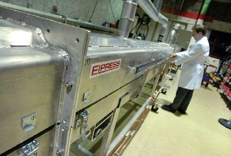
Elpress hydraulic and mechanical tool systems are some of the safest on the market. Safety requires that instructions and directions are available and followed closely. Each Elpress tool is therefore accompanied by detailed instructions on how to use the tool. These instructions should be read carefully before use, in the best interests of the operator.
Correct use of the tools:
• increases productivity
• increases tool life
• ensures the quality of work done
• minimises the risk of accidents
Below are some simple and common rules that we at Elpress recommend all operators to follow:
• Before starting work with a crimp tool, a thorough visual inspection should be carried out. Pump, crimp head, forks, couplings, hoses and other accessories must be checked to ensure that they are faultless and clean. The correct placement of the inserts in the forks should also be checked before starting work.
• All operators must wear personal protective equipment such as A51 gloves, goggles and safety shoes.
• Hydraulic pressure must not be applied to a hose that is heavily bent or knotted. The hose is made for particularly high pressure and cannot be replaced by another type.
• Hydraulic tools must never be carried in the hose or coupling.
• Operate with caution, do not drop heavy objects on the hydraulic hose. This can damage the steel reinforcement and cause leakage. If leakage occurs, oil under high pressure may come into contact and penetrate the skin resulting in internal injury. If this happens, contact a doctor immediately.
• The tools must be serviced and calibrated at regular intervals.
• Make sure that the correct tool or tool insert has been selected for the terminal and conductor to be crimped.
• Check that the installation is unpowered before carrying out work. The tools are not designed for “Live working”.
• Keep in mind that there is very high crimp pressure during work. Therefore, never stand in front of a tool in the direction of crimping force.
• Pay attention to the risk of crushing and cutting injuries during work. This applies to all types of crimping tools and cable cutters.
• If there is a suspicion of failure of a crimp system, always contact the Elpress Service Centre.
In order to ensure that the tool has achieved the predetermined shape change for each cable terminal, the crimp result shall be measured. This shape change provides both mechanical strength and good electrical properties. Hexagonal crimping
For terminals and through connectors of copper the following applies:
• The ”N” dimension is checked in the direction of the crimp.
• Measure with calipers and compare with the table’s ”N” dimensions.
• If the measurement result exceeds the ”N” dimension (according to the table that follows) after correct contact crimping, contact the Elpress service centre.
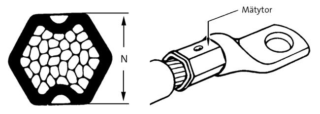
Crimp die table type KRF/KSF with Dual dies (N measurement)
Type
with
Crimp die table type KRD/KSD (N-measurement)
Type
Crimp die table type KRF/KSF (N-measurement)
Type KRF/KSF with B-dies
Crimp die table type KRT/KST (N-measurement)
Type KRT/KST with B-dies
For Cu branching sleeves, the ”h” dimension must be checked. This is done at the maximum height of the crimped oval, preferably with calipers. The measurements are compared to the table below. If the ”h” measurement is exceeded, after a contact crimping, contact the nearest Elpress service centre. See measurement points on the image below.
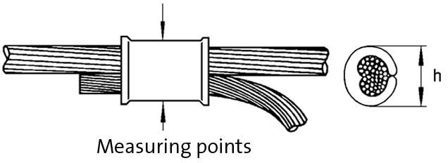
C-die
For Al terminals, the measurement ”T” must be checked, which is measured at the bottom of the indent that the punch has achieved on the terminal. This is best done with special calipers, contact Elpress if necessary. Compare measured ”T” measurement with table. If the ”T” measurement is exceeded, after indented crimping, contact the nearest Elpress service centre. See measurement points on the image below.
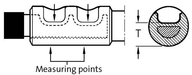
13P37M/P2537M 13P37D/P2537D
400B 13P37M/P2537M 13P37D/P2537D 22.5 400 P40M P36/40/44D 22.8
500B P44M P36/40/44D 24.5
500A P2552M P2552D 31.0 630A P2552M P2552D 31.0
W60M W60D 36.0
W60M W60D 36.0
W60M W60D 36.0
W70M W70D 41.0
Users/installers of bolted connectors always have to adhere to, and follow electrical codes and norms in the local region where they are making such installations. The information below is general and hence, should never be seen as an installation instruction. The installation of a terminal with bolt joint for electrical transmission requires special attention. It is important that this is done in a correct manner, as important as the contact crimping at the other end of the terminal as described above. The joint must achieve a sufficiently high clamping force, distributed in a desirable manner and ensure the electrical properties over a very long time under high and varying loads of different characteristics. It is very important to follow the installation instructions. These are based on theoretical calculations, verified tests and experience from field studies. Tightening must be carried out in a controlled manner using torque tools, where the relevant screw is tensioned to the specified torque. The accuracy of the tool is of great importance. The clamping force of a properly tightened screw shall create a contact area large enough to ensure good conductivity, without the risk of overheating. In order for the clamping force to be distributed evenly and create a sufficiently large contact area, hard flat washers must always be used, type BRB HB200 SMS 70, under screw head and nut. See image below. This applies regardless of the hardness of the conductive materials (which are softer than HB200). Otherwise, there is risk of large deformation of the conducting material that reduces the tension, which can increase the risk of inadequate contact area and overheating.
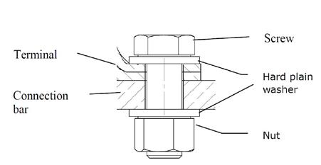
Bolt joints.
Tension washers
The use of different types of locking elements or spring washers often increases the risk of settlement. If a spring washer of type DIN 6796, with a very high clamping force, is positioned and secured between e.g. nut and the hard flat washer, it can provide an increased margin towards excessively high settlement. The diameter of the tension washer should be less than or equal to the flat washer’s, even after tightening fully. Otherwise, the risk of settlement at the outer edge of the flat washer increases where the clamping forces are concentrated. When using spring washers, 1 is sufficient and it is preferably placed on the opposite side of the terminal.
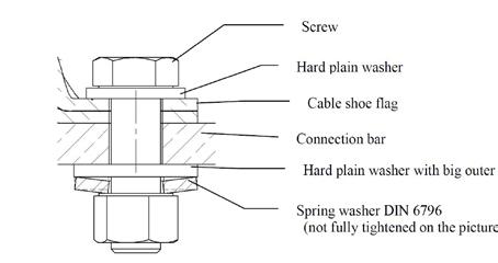
Bolt joint with spring washer.
Mounting the terminal against the connection rail
Max. 2 terminals of the same size on the same screw. Current load should be checked.
Preparatory:
• Clean contact surfaces from dirt, oxide layers and grease using a steel brush and denatured alcohol. This is especially important for aluminium. Surfaces that are tinned, nickel-plated, silver plated must not be brushed.
• Petroleum jelly or contact grease reduces corrosion risk on cleaned surfaces
Fastener selection:
• Screws and nuts of strength class 8.8.
• Greased galvanized screws provide the least dispersion of the pre-tension force.
• Choose stainless A4-80 in environments when there is a high risk of corrosion.
Selection of washers:
• Always select hard flat washers of the BRB, HB200 type.
• The tension washer can normally be excluded. If a tension washer of type DIN 6796 is used, it must be placed between the screw head/nut and the flat washer. It must never be placed directly against an electrical contact surface without a flat washer in between. The flat washer must have an external diameter at least as large as the tension washer.
• 1 spring washer is sufficient and it should be placed on the rear of the busbar, between nut and hard flat washer, see diagram.
Installation:
• The screws must be tightened with torque tools so that tightening is controlled.
• Torque wrenches must be calibrated regularly. Oil the screw when installing. Even if the torque is recorded correctly, the pre-tension force depends entirely on the friction.
• Tightening torque according to the table above. Accuracy better than ±5%.
• The terminal palm and busbar may be of different materials.
Al/Al gives a weaker joint. It is important to clean and use contact grease. Tension washer + flat washer can reduce the risk of settlement.
Al/Cu gives a higher risk of corrosion and settlement, use contact grease.
Cu/Al provides low risk of galvanic corrosion when the rail is made of Al. Cu/CU provides the best joint, good contact and small risk of settlement.
Mv = tightening torque (Nm)
Ff = pre-tensioning force (kN)
p = flat pressure (N/mm²)
FZB = electroplated + gloss chromed
FZY = electroplated + hard chromed
FZM = FZM= mechanically galvanized
* (FZB, FZY, FZM)
A4/80
Our service department maintains, repairs, checks, calibrates and certifies Elpress tools and power sources. Following a review of the equipment by the service department, certificates are issued that verify the performance of the tools. To ensure that your crimped terminals maintain a high and even level of quality, regular checks shall be done of the crimping tools.
We offer:
• Contract preventive maintenance, Elpress Basic and Elpress Advance
• Calibration of tools
• Repairs (servicing of tools)
• Rental of crimping equipment
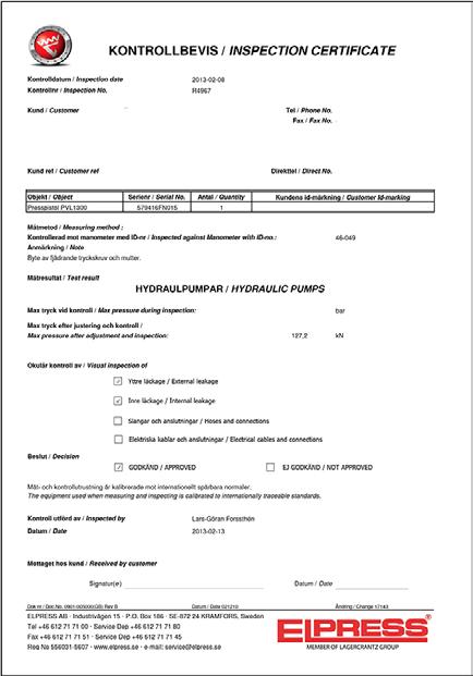
Elpress service offers a flexible service solution for increased security with fast service and high availability.
Our service agreements are available in 2 levels, Elpress Basic and Elpress Advance. To sign a service agreement with Elpress means the following:
• Planned and preventive maintenance ensures better performance for your equipment.
• Regular service intervals minimise the risk of unforeseen stoppages by indicating any safety or functional defects and recommending measures to avoid these problems
• Regular service intervals are normally implemented every 12 months for a fixed price
• The price is based on the service level and tool equipment.
• A certificate is issued after the equipment has complied with calibration requirements
• Calibration can also be done on-site at the customer
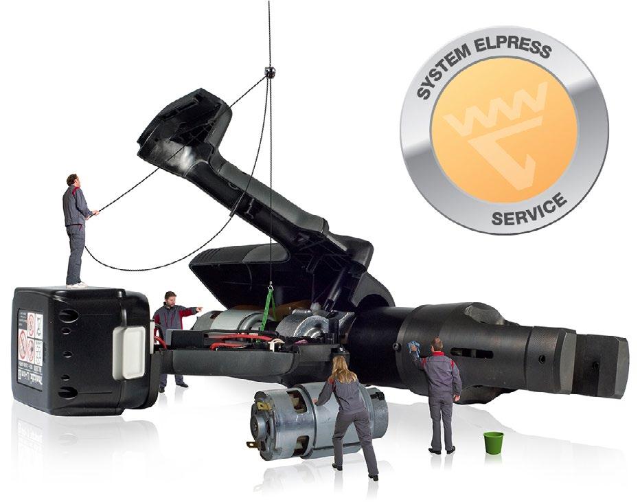
This forms the basis of a service agreement and includes the following points:
• General inspection of the tool
• Safety aspects according to declaration of conformity (compliance with the Machinery Safety Directive, Low Voltage Directive, EMC Directive).
• Function test
• Checking of accessories, e.g. crimp dies etc.
• Issue of Certificate
• The inspection follows Elpress final inspection and acceptance inspection requirements.
Elpress Advance includes:
• Elpress Basic + corrective maintenance Includes calibration with certification and consumables repairs at a fixed price.
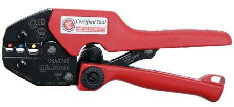
Calibration follows the same points and requirements as Elpress Basic, but it is the customer’s responsibility to submit the tool for calibration.
Sometimes the accumulation of work can be greater than can be expected, or individual projects may require more resources than usual and then it is possible to rent equipment at Elpress. When repairing equipment for a company, Elpress can rent tools to the company if required, until the original equipment is repaired and returned.
Send the Product registration form to Elpress and Elpress Basic is included for free the first year.
More information is available from the service department: https://www.elpress.net/en/products/ system-elpress/service/
Elpress uses copper, brass and aluminium as terminal materials.
The copper and brass products are electrolytically tin plated for increased corrosion resistance. In a bimetal (copper aluminium) terminal, the copper part is untreated.
Brass is mainly used for flat pin sleeves in areas up to 6 mm², where good suspension properties are desired. Brass is an alloy of about 70% copper and about 30% zinc and has very good cold form properties.
The copper used by Elpress for terminals has a purity of at least 99.95 %. Its excellent properties for use in electrical terminals are among the following:
• high conductivity (only silver is better)
• high corrosion resistance
• good formability
• good sealability
In manufacturing the neck of the terminal element is soft soldered in order to obtain as good form properties and good enclosure around the conductor as possible during the contact crimping.
This then provides a terminal that exhibits low transitional resistance and good mechanical properties.
The aluminium used for through connectors and cable terminals has a purity of at least 99.7 % and its excellent qualities are:
• low weight
• strong, in relation to its weight
• good electrical conductivity, approximately 60% of the conductivity of copper
• easy to work with
Cable standard IEC 60228 provides:
Information about materials, construction and resistance values for both copper and aluminium conductors.
Class 1 solid conductor
Class 2 stranded conductor
Class 5 flexible conductor
Class 6 highly flexible conductor
KR/KS, KRF/KSF, KRFS, KRT/KST UL approved in accordance with file no. E205350. UL certified products are delivered with UL marking on the label including the UL file number and/or certification code for control by an UL inspector. The certificate can be downloaded at UL Product IQ.
MCM and AWG cross-reference table to the corresponding area in mm²
Remarks:
1. The information in this table comes from catalogues published by respected cable providers and does not refer to official standards.
2. The types relating to AWG vary depending on the different design of the conductors, i.e. the number of strands.
AWG > 20 refers to single strand conductors.
AWG ≤ 20 refers to multi stranded conductors.
Exact areas for specific number of strands can be found in cable provider catalogues.
Elpress is one of Europe’s leading manufacturers of electrical crimping systems and has 60 years of experience in application solutions in everything from nuclear power plants to small electronic devices.
Products in electrical applications are subjected to both mechanical and thermal loads. Elpress invests considerable resources to achieve success through continuous product development towards better value, quality and performance.
For this purpose there is modern laboratory equipment for, among other things:
• High current testing
• Mechanical tensile strength testing
• Cyclic current testing
• Vibration testing
• Corrosion testing
• Resistance determination
The activities also include theoretical studies, prototype development, technical documentation and advice etc. The competence of the staff together with good laboratory and calculation aids is a strong competitive tool both in terms of consultancy services and their own development projects.
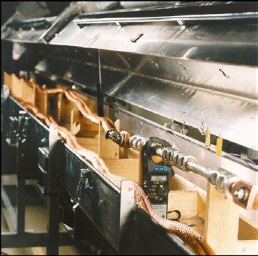

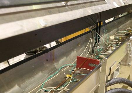
Tests according to IEC 61238-1-1 in own premises
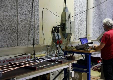
The modern and easy-to-use cable terminations for 12 to 36 kV PEX insulated cable consisting of prefabricated modules or even fully finished terminations, provide no or very little restriction in the use of terminals with type designations AK, AKK or KRF. This also includes the ”top pins” with the type designation AKP.
One detail to take into account when using KRF terminals outdoors is that this terminal is equipped with an inspection hole that must be sealed. Your supplier of cable terminations can provide its specific solution.
Terminals type AK, AKK or ”top pin” AKP can today be used on high voltage cable terminations where solutions are available up to 84 kV. In case of doubt, always consult with your cable termination supplier for specific solutions for different issues regarding technical details regarding the design.
When installing cable terminations for oil impregnated paper cable where an oil reservoir is used, manufacturers usually have their own specially designed solutions for the conductor connections.
Terminal type AK is used at termination of an Al conductor for connection to busbars and apparatus sockets
Terminals of type AKK are used at the end of an Al conductor for connection to a Cu bus bar.
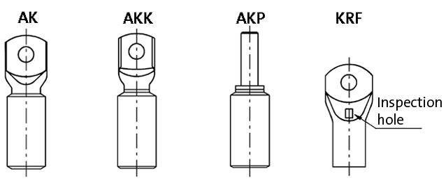
Through connectors type AS
Through connectors type AS used when splicing aluminium-conductors.
Through connectors of type AKS are used for jointing of Al conductors to Cu conductors.
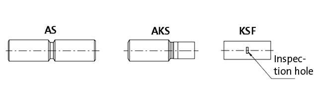
In Sweden, four types of splice are currently used in the voltage range 12 to 36 kV. These are tape, heat shrink, cold shrink and push-on joints. All these joints are designed to accept AS, AKS and KSF through connectors. No connectors with conical ends are required today. Different manufacturers have their own solutions that are designed to take care of, for example, the punch holes and the distance between the insulation edge and the through connector.
Always note the joint manufacturer’s directions regarding maximum lengths and diameters of the connectors. If you are not sure, or if the installation instructions do not indicate what you are considering, consult your joint supplier.
At higher voltages, e.g. 52 and 84 kV, other requirements are placed on the through connectors depending on the joint design and design. However, there are solutions where ”normal” through connectors are used together with filler materials in the voltage range up to 145 kV.
PEX insulated cable against oil impregnated cable
When installing a transition splice between cables with oil impregnated insulation and PEX insulation at voltages of 12 kV and above, connectors with partitions must be used, regardless of the splicing method and make. AKS, KSF-M and AS connectors always have partitions.
Oil impregnated against oil-impregnated cable
When splicing two cables with this type of insulation, connectors of type AS, AKS, or KSF can be used, whether it is an oil tube connector or a ”dry” heat shrink connector.


System Elpress symbolizes our cornerstones – safety and quality. In order to achieve a secure connection, we offer certified solutions of the combination cable, terminal and tool.
For perfect crimping connections, Elpress Academy offers Crimping Technology training and seminars.


For non-standard solutions you can consult us and let our own production and laboratory verify your solution. A preventive service maintenance of the tool is the base for the system to work.
Certification, Academy, Consulting and Service is System Elpress – your secure connection!

We manufacture tested systems for electrical connectors and their tools. You get a secure connection.
We offer:
Tool delivered with a calibration certificate
Verified and tested combination of cable, terminal and tool
Certified solutions for customized product development
Product approval in accordance with IEC, UL, DNV and CSA
Third part quality and environment certification in accordance with ISO9001 and ISO14001

In order to achieve a secure connection we offer certified solutions of the combination cable, terminal and tool. This is so that you as customer can feel secure when you use our system and be sure that a safe connection will be made when our products are used correctly.
The System includes:
• Terminal, connector
• Crimping tool
• Correct cable
• Trained and skilled operator
The system is developed and tested in accordance with existing norms and standards, for example IEC.
Product development
• Customized solutions
• Specialized segment solutions
• Leading technology in our industry
• Innovative products
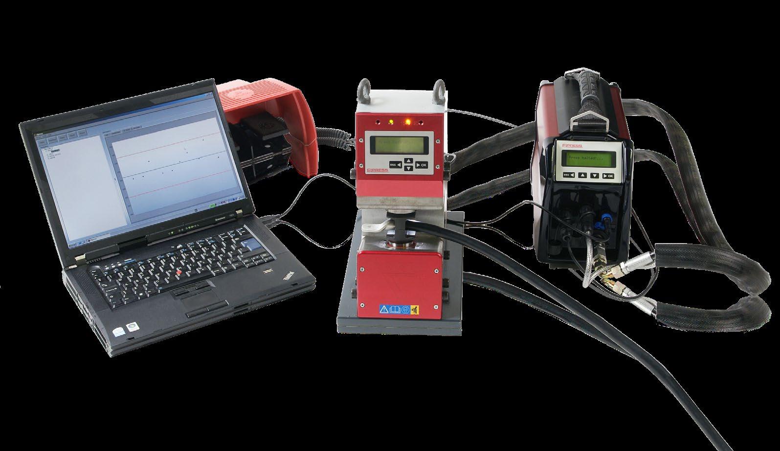
Quality & environment certified and approved according to
• ISO 14001
• ISO 9001
• DNV
• UL

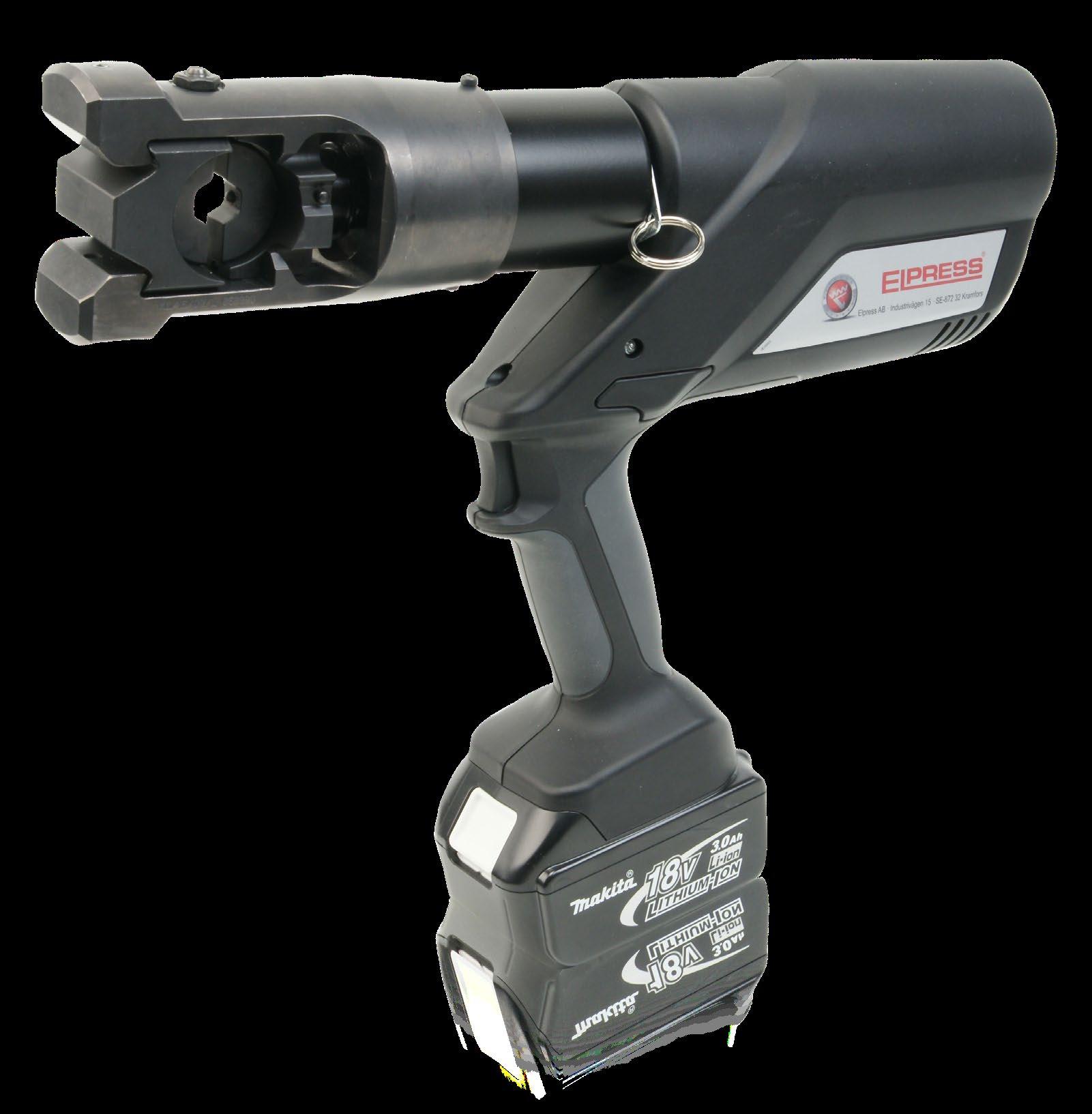
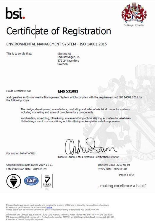
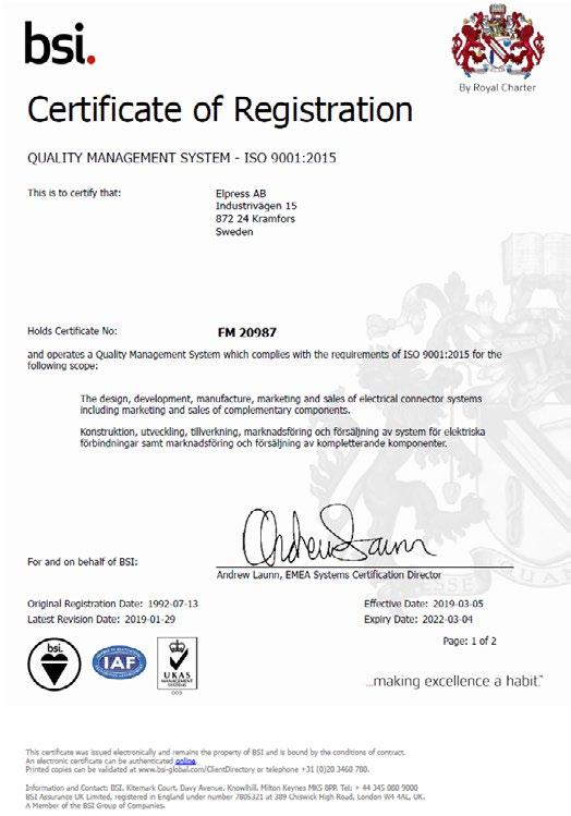
We have the necessary resources for you to maintain the highest quality

We offer:
Tests in laboratory
Problem solving
Technical and customer support
Customized terminals and tools
Audits and validations at your premises

We have been developing, manufacturing and marketing complete cable crimping systems for electrical connectors with more than 50 years of experience. We have therefore the best knowledge and equipment for your requirements and demands.
You will have access to:
• Our Technical Departments that designs and develops customized products and solutions according to your requirements.
• Our Produtction Team who can manufacture unique solutions.
• Our laboratory who can supply for example – Electrical tests – Mechanical tests
– Corrosion- and environmental tests
Contact us and let us assist you.
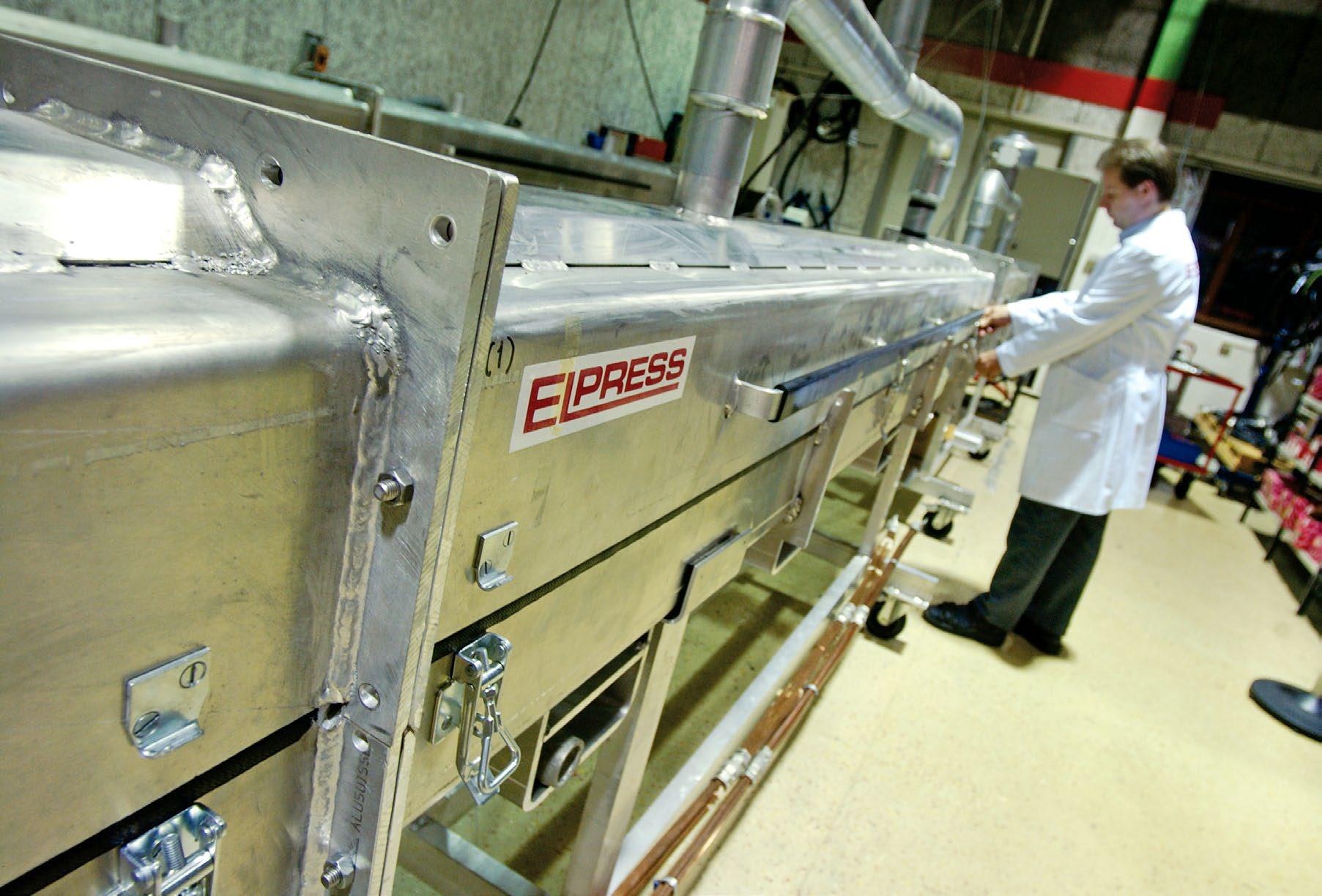
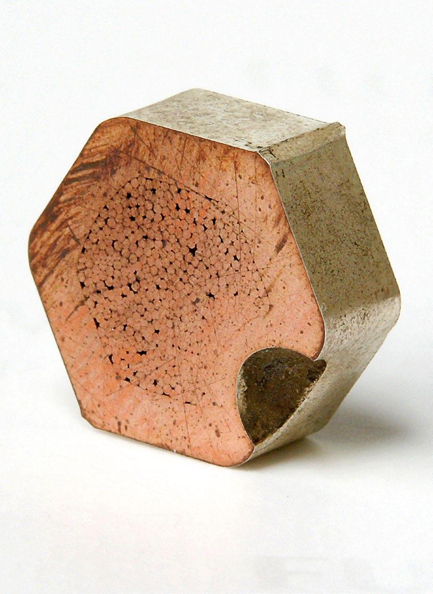

A well educated personnel ensures the final quality of products and services. Our Academy certificate is a Quality Assurance Document between you and your customer.

We focus on the following four areas:
Utility sector and installers
Transformer manufacturers
Traction/Train manufacturers
Wind Power manufacturers
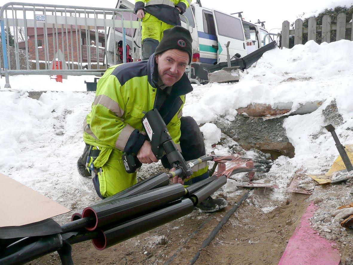
General training for all staff. Provides a general knowledge of crimping in all areas;
• Terminals below 10 mm2
• Cu-connectors over 10 mm2
• Al-connectors from 16 mm2
• Cu-branching
• Bolt connections
• Deep earthing
• Standards and requirement
• Safety and maintenance
• Quality inspection
The program combines theory and practice and concludes with a written test. Course participants will receive certificate after the completion of their training.
Possibility to customize the training so the content fits the needs of the company.


For operators who work daily in the production. The aim is to train personnel in the special conditions applying in the transformer manufacturing. The training focuses on areas like;
• Management of tools
• Calculations and preparation for crimping
• Work procedure
• Quality inspection
• Safety in use
• Preventive maintenance in daily production
The training consists of a theoretical and a practical part and ends with a written test. Course participants will receive certificate after the completion of their training.
We can provide education for all personnel such as operators, supervisors, designers and quality departments. The education includes a thorough knowledge of calculations, tool selection and management, problems and solutions and quality assessment.
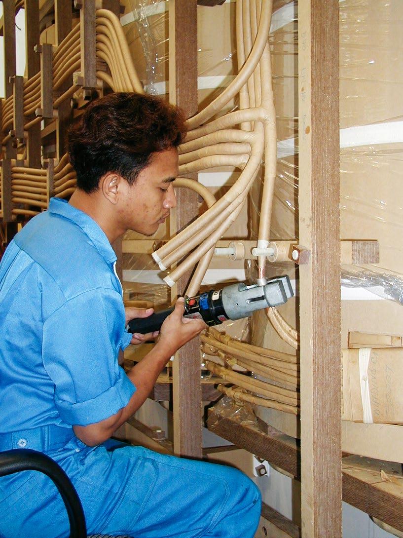

Each training has a level that suits everyone, such as operators, designers, supervisors and quality managers. In addition, there is the possibility to customize the training so that the content fits the needs of the company. You also decide whether the training should be company-based or held in Elpress’s training facilities.
Educate staff in the special demands and external conditions that apply in the manufacturing of rail traffic. The training concerns;
• Management of tools
• Work procedure
• Elpress Dual-technology
• Crimp technique

• Quality inspection
• Safety in use
• Preventive maintenance in daily production
The training consists of a theoretical and a practical part and ends with a written test. Course participants will receive certificate after the completion of their training.
Education for all personnel such as operators, supervisors, designers and quality departments. Provides a thorough knowledge of calculations, tool selection and management, problems and solutions and quality assessment. Completed training gives a certificate.
Educate staff in the special demands and external conditions that apply in the manufacture of wind turbines. The training concerns;
• Management of tools
• Work procedure
• Elpress Dual-technology
• Crimp technique
• Quality inspection
• Safety in use
• Preventive maintenance in daily production
The training consists of a theoretical and a practical part and ends with a written test. Course participants will receive certificate after the completion of their training.
Education for all personnel such as operators, supervisors, designers and quality departments. Provides a thorough knowledge of calculations, tool selection and management, problems and solutions and quality assessment. Completed training gives a certificate.
Preventive maintenance agreements secure the quality of your connection
We offer:
Preventive maintenance agreements
Calibration of certified tools
Repairs/maintenance of tools
Crimping systems for rent
Sales of spare parts
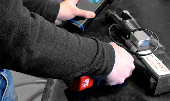
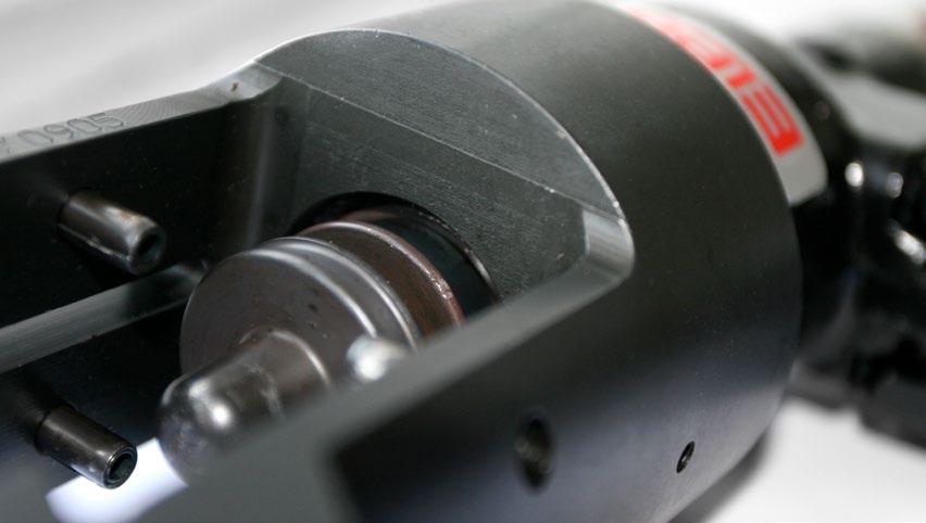
Our Service offers you a flexible solution for enhanced security, with rapid service and high availability:
• Planned and preventive maintenance guarantees high performance for your equipment.
• Regular service intervals minimize the risk of unforeseen stoppages by indicating any safety or functional defects and by recommending measures to avoid such problems.
• Regular service intervals are normally implemented every 12 months at a fixed price.
Elpress Basic service agreement includes following points:
• General inspection of the tool
• Safety aspects in accordance with declaration of conformity
• Function test
• Checking of accessories, e.g. crimp dies etc.
• Issue of Certificate
The inspection follows Elpress final inspection and acceptance inspection requirements.

• The price is based on the service level solution and equipment.
• A certificate is issued after the equipment has complied with calibration requirements.
The maintenance can be performed at your premisses.
Elpress Advance service agreement includes following points:
• Elpress Basic + corrective maintenance
Includes the Calibration/certification and wear & tear repairs at a fixed price.
The calibration follows the same inspection points and requirements as Elpress Basic, but it is the customer’s responsibility to send the tool for calibration.
Send the Product registration form to Elpress and Elpress Basic is included for free the first year.
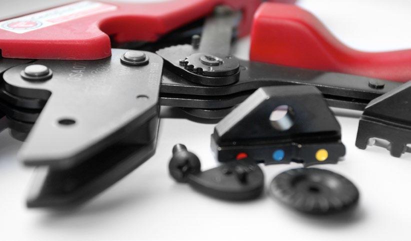
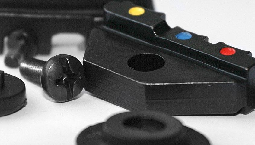

7:2
3:13
3:14
3:13
3:13
7:2
7:2 13B10 6:25 13B11 6:23 13B11 6:24 13B12 6:24 13B12 6:25 13B13 6:23 13B14 6:24 13B14 6:25 13B14,5 6:23 13B16 6:24 13B16 6:25 13B17 6:23 13B18 6:25 13B19 6:24 13B19 6:25 13B20 6:23 13B22 6:23 13B22 6:24 13B22 6:25 13B24 6:25 13B25 6:23 13B25 6:24 13B26 7:9 13B26 6:25 13B26 6:31 13B27 6:23 13B27 6:24 13B30 6:23 13B30 6:24 13B30 6:25 13B32 7:9 13B32 6:23 13B32 6:24 13B32 6:25 13B32 6:31 13B38 6:23 13B8 6:23 13B8 6:24 13B9 6:23 13B9 6:24
13BC13 6:25 13BC15 6:25 13C21B38 6:35 13CB10 6:37 13CB11 6:35 13CB11 6:36 13CB12 6:36 13CB12 6:37 13CB13 6:35 13CB14 6:36
6:37
6:35
6:36
6:37
6:35
6:37
6:36
6:37
6:35 13CB22 6:35 13CB22 6:36 13CB22 6:37 13CB24 6:37 13CB25 6:35 13CB25 6:36 13CB26 6:37 13CB27 6:35 13CB27 6:36 13CB30 6:35
13CB30 6:36 13CB30 6:37 13CB32 6:35 13CB32 6:36
6:37
6:35 13CB8 6:36 13CB8,5 6:37 13CB9 6:35 13CB9 6:36 13CBC13 6:37 13CBC15 6:37 13DB11 6:18 13DB13 6:18 13DB14,5 6:18 13DB17 6:18 13DB20 6:18 13DB22 6:18 13DB25 6:18 13DB27 6:18 13DB30 6:18 13DB32 6:18 13DB8 6:18 13DB9 6:18 13DCB11 6:18 13DCB11 6:49 13DCB13 6:18 13DCB13 6:49 13DCB14,5 6:18 13DCB14,5 6:49 13DCB17 6:18 13DCB17 6:49 13DCB20 6:18 13DCB20 6:49 13DCB22 6:18 13DCB25 6:18 13DCB27 6:18 13DCB30 6:18 13DCB32 6:18 13DCB8 6:18 13DCB8 6:49 13DCB9 6:18 13DCB9 6:49
13P120150D 6:29
13P120150M 6:29
13P185240D 6:29
13P185240M 6:29
13P32M 6:28
13P37D 6:28
13P37M 6:28
13P5095D 6:29
13P5095M 6:29
13R12DR 6:28
13R13DR 6:28
13R15DR 6:28
13R16DR 6:28
13R18DR 6:28
13R18MR 6:28
13R20DR 6:28
13R20MR 6:28
13R6DR 6:28
13R7DR 6:28
13R8DR 6:28
13R9DR 6:28 20DCB22 6:49 20DCB25 6:49 20DCB27 6:49 20DCB30 6:49 20DCB32 6:49 401-12 3:18 404-1 3:18 405-3 3:18
408-6-F 3:17
408-6-M 3:17
408-8-F 3:17
408-8-M 3:17
A0,14-6ET 2:4
A0,14-6ETD 2:6
A0,14-6ETT 2:5
A0,14-8ET 2:4
A0,14-8ETD 2:6
A0,14-8ETT 2:5
A0,25-6ET 2:4
A0,25-6ETT 2:5
A0,25-8ET 2:4
A0,25-8ETD 2:6
A0,25-8ETT 2:5
A0,34-6ET 2:4
A0,34-6ETD 2:6
A0,34-6ETT 2:5
A0,34-8ET 2:4
A0,34-8ETD 2:6
A0,34-8ETT 2:5
A0,5-10ET 2:4
A0,5-10ETD 2:6
A0,5-10ETT 2:5
A0,5-6ET 2:4
A0,5-6ET2 2:8
A0,5-6ETD 2:6
A0,5-6ETT 2:5
A0,5-6ETT2 2:9
A0,5-6ETW2 2:10
A0,5-8ET 2:4
A0,5-8ET2 2:8
A0,5-8ETD 2:6
A0,5-8ETT 2:5
A0,5-8ETT2 2:9
A0,5-8ETW2 2:10
A0,75-10ET 2:4
A0,75-10ET2 2:8
A0,75-10ETD 2:6
A0,75-10ETT 2:5
A0,75-10ETT2 2:9
A0,75-10ETW2 2:10
A0,75-12ET 2:4
A0,75-12ET2 2:8
A0,75-12ETD 2:6
A0,75-12ETT 2:5
A0,75-12ETT2 2:9
A0,75-12ETW2 2:10
A0,75-6ET 2:4
A0,75-6ETD 2:6
A0,75-6ETT 2:5
A0,75-8ET 2:4
A0,75-8ET2 2:8
A0,75-8ETD 2:6
A0,75-8ETT 2:5
A0,75-8ETT2 2:9
A0,75-8ETW2 2:10
A0503FLS5 1:9
A0503FLS8 1:9
A0514SR 1:6
A0522R 1:4
A0532G 1:5
A0532R 1:4
A0543R 1:4
A0553R 1:4
A0802HA 1:11
A0802HO 1:11
A0819SR 1:6
A0819SRK 1:6
A0824SK 1:7
A0825SFK 1:7
A0832G 1:5
A0832R 1:4
A0837G 1:5
A0837R 1:4
A0843G 1:5
A0843R 1:4
A0853R 1:4
A1,5-10ET 2:4
A1,5-10ETD 2:6
A1,5-10ETT 2:5
A1,5-12ET 2:4
A1,5-12ET2 2:8
A1,5-12ETD 2:6
A1,5-12ETT 2:5
A1,5-12ETT2 2:9
A1,5-12ETW2 2:10
A1,5-18ET 2:4
A1,5-18ETD 2:6
A1,5-18ETT 2:5
A1,5-6ET 2:4
A1,5-6ETD 2:6
A1,5-6ETT 2:5
A1,5-8ET 2:4
A1,5-8ET2 2:8
A1,5-8ETD 2:6
A1,5-8ETT 2:5
A1,5-8ETT2 2:9
A1,5-8ETW2 2:10 A10-12ET 2:4
A10-12ETD 2:6
A10-12ETT 2:5
A10-14ET2 2:8
A10-14ETT2 2:9 A10-14ETW2 2:10 A10-18ET 2:4 A10-18ETD 2:6 A10-18ETT 2:5 A1-10ET 2:4
A1-12ET2 2:8 A1-12ETD 2:6 A1-12ETT 2:5 A1-12ETT2 2:9 A1-12ETW2 2:10
A1503FLS5 1:9
A1503FLS8 1:9
A1503FLSF5 1:10
A1503FLSF8 1:10 A1504HA 1:11 A1504HO 1:11 A1505FLS5 1:9 A1505FLS8 1:9 A1505FLSF5 1:10 A1505FLSF8 1:10 A1507FLS 1:9
A1507FLSF 1:10 A1507FLSH 1:9 A1507FLST 1:9 A1507H 1:10 A1510R 1:4 A1515PSK 1:8 A1518SFL 1:7 A1519SR 1:6 A1519SRK 1:6 A1525SK 1:7 A1529SF 1:7 A1529SFN 1:7 A1530SFB 1:7 A1532G 1:5 A1532R 1:4
A1535SKW 1:8
A1537G 1:5
A1537GB 1:5
A1537GS 1:5
A1537R 1:4
A1543G 1:5
A1543GB 1:5
A1543K 1:6
A1543R 1:4
A1553G 1:5
A1553R 1:4
A1565G 1:5
A1565R 1:4
A1585R 1:4
A16-12ET 2:4
A16-12ETD 2:6
A16-12ETT 2:5
A16-18ET 2:4
A16-18ETD 2:6
A16-18ETT 2:5
A1-6ET 2:4
A1-6ETD 2:6
A1-6ETT 2:5
A1-8ET 2:4
A1-8ET2 2:8
A1-8ETD 2:6
A1-8ETT 2:5
A1-8ETT2 2:9
A1-8ETW2 2:10
A2,08-8ET 2:4
A2,08-8ETD 2:6
A2,08-8ETT 2:5
A2,5-10ET 2:4
A2,5-10ET2 2:8
A2,5-10ETD 2:6
A2,5-10ETT 2:5
A2,5-10ETT2 2:9
A2,5-10ETW2 2:10
A2,5-12ET 2:4
A2,5-12ETD 2:6
A2,5-12ETT 2:5
A2,5-13ET2 2:8
A2,5-13ETT2 2:9
A2,5-13ETW2 2:10
A2,5-18ET 2:4
A2,5-18ETD 2:6
A2,5-18ETT 2:5
A2,5-8ET 2:4
A2,5-8ETD 2:6
A2,5-8ETT 2:5
A2500E 1:11
A2505FLS5 1:9
A2505FLS8 1:9
A2505FLSF5 1:10
A2505FLSF8 1:10
A2505HA 1:11
A2505HO 1:11
A2507FLS 1:9
A2507FLSF 1:10
A2507FLSH 1:9
A2507FLST 1:9
A2507H 1:10
A2510R 1:4
A2513R 1:4
A25-16ET 2:4
A25-16ETD 2:6
A25-16ETT 2:5
A2517PSK 1:8
A25-18ET 2:4
A25-18ETD 2:6
A25-18ETT 2:5
A2519SR 1:6
A2519SRK 1:6
A25-22ET 2:4
A25-22ETD 2:6
A25-22ETT 2:5
A2524SFL 1:7
A2527SK 1:7
A2529SF 1:7
A2529SFN 1:7
A2530SFB 1:7
A2532G 1:5
A2532R 1:4
A2535SKW 1:8
A2537G 1:5
A2537GS
A2543K 1:6
A2543R
A6-18ETW2 2:10
AK1000-1 5:3
AK1000-2 5:3
AK1200 5:3
AK120-10 5:3
AK120-12 5:3
AK150-10 5:3
AK150-12 5:3
AK150-16 5:3
AK16-6 5:3
AK16-8 5:3
AK185-10 5:3
AK185-12 5:3
AK185-16 5:3
AK240-12 5:3
AK240-16 5:3
AK25-6 5:3
AK25-8 5:3
AK300-12 5:3
AK300-12SOLID 5:3
AK300-16 5:3
AK300-16SOLID 5:3
AK300-20 5:3
AK35-6 5:3
AK35-8 5:3
AK400-12 5:3
AK400-16 5:3
AK400-20 5:3
AK500A-1 5:3
AK500A-16 5:3
AK500A-2 5:3
AK500A-20 5:3
AK500B-1 5:3
AK500B-16 5:3
AK500B-2 5:3
AK500B-20 5:3
AK50-10 5:3
AK50-12 5:3
AK50-8 5:3
AK630A-1 5:3
AK630A-2 5:3
AK70-10 5:3
AK70-12 5:3
AK70-8 5:3
AK800-1 5:3
AK800-2 5:3
AK95-10 5:3
AK95-12 5:3
AK95-8 5:3
AKK1000-1 5:6
AKK1000-1-16 5:6
AKK1000-2 5:6
AKK1200 5:6
AKK120-10 5:6
AKK120-12 5:6
AKK120-16 5:6
AKK150-10 5:6
AKK150-12 5:6
AKK150-16 5:6
AKK16-8 5:6
AKK185-10 5:6
AKK185-12 5:6
AKK185-16 5:6
AKK240-10 5:6
AKK240-12 5:6
AKK240-16 5:6
AKK25-12 5:6
AKK25-8 5:6
AKK300-12 5:6
AKK300-12SOLID 5:6
AKK300-16 5:6
AKK300-16SOLID 5:6
AKK300-20 5:6
AKK300-20SOLID 5:6
AKK400-12 5:6
AKK400B-12 5:7
AKK400B-16 5:7
AKK500A-1 5:6
AKK500A-16 5:6
AKK500B-2 5:6
AKK500B-20 5:6
A6-18ET2 2:8
A6-18ETD
A6-18ETT
A6-18ETT2
AKK300B-12 5:7
AKK300B-16 5:7
AKK35-12 5:6
AKS185-185 5:9
AKS185-70 5:9
AKS185-95 5:9
AKS240-120 5:9
AKS240-150 5:9
AKS240-185 5:9
AKS240-240A 5:9
AKS240-35 5:9
AKS240-50 5:9
AKS240-70 5:9
AKS240-95 5:9
AKS25-10 5:9
AKS25-10S 5:8
AKS25-16 5:9
AKS300-150 5:9
AKS300-185 5:9
AKS300-240A 5:9
AKS300B-185 5:8
AKS300B-240A 5:8
AKS300SOLID-300 5:9
AKS35-10 5:9
AKS35-10S 5:8
AKS35-16 5:9
AKS35-25 5:9
AKS400-150 5:9
AKS400-185 5:9
AKS400-240A 5:9
AKS400-300A 5:9
AKS400B-240A 5:8
AKS400B-300A 5:8
AKS50-10 5:9
AKS50-10S 5:8
AKS50-16 5:9
AKS50-25 5:9
AKS50-35 5:9
AKS50-50 5:9
AKS70-10S 5:8
AKS70-35 5:9
AKS70-50 5:9
AKS70-70 5:9
AKS95-10 5:9
AKS95-10S 5:8
AKS95-16 5:9
AKS95-25 5:9
AKS95-35 5:9
AKS95-50 5:9
AKS95-70 5:9
AKS95-95 5:9
AS1000-1 5:4
AS120 5:4
AS1200 5:4
AS120-95 5:5
AS150 5:4
AS150-120 5:5
AS150-50 5:5
AS150-70 5:5
AS150-95 5:5
AS16 5:4
AS1625 5:4
AS185 5:4
AS185-150 5:5
AS185-95 5:5
AS240 5:4
AS240-120 5:5
AS240-150 5:5
AS240-185 5:5
AS240-95 5:5
AS25 5:4
AS25-16 5:5
AS300 5:4
AS300-240 5:5
AS300B 5:5
AS300SOLID 5:4
AS35 5:4
AS35-25 5:5
AS400 5:4
AS400-300 5:5
AS400B 5:5
AS400SOLID 5:4
AS50 5:4
AS500A 5:4
AS500B 5:4
AS50-25 5:5
AS50-35 5:5
AS630A-1 5:4
AS630A-2 5:4
AS70 5:4
AS70-50 5:5
AS800-1 5:4
AS95 5:4
AS95-25 5:5
AS95-35 5:5
AS95-50 5:5
AS95-70 5:5
B0457H4 3:12
B0457H5 3:12
B0502HA 3:10
B0502HO 3:10
3:11
B1003FLS5 3:8 B1003FLS8 3:8 B1003FLSV5 3:9
B1003H 3:10 B1007HN 3:10
B10-10R 4:14
B10-12R 4:14 B10-5R 4:14
B10-6R 4:14
B16 6:41
B16 6:42
B16-10R 4:14
B16-12R 4:14
B16-16R 4:14
B16-5R 4:14
B16-6R 4:14
B16-8R 4:14 B16NP 7:11 B16NP 7:11
B16NP 7:9 B16NP 7:9 B16NP 6:31 B16NP 6:31 B16NP 6:46 B16NP 6:46 B16SR 4:20 B17 6:22 B17 6:34
B17 6:40 B18 6:24 B18 6:36 B18 6:42
B1807H4 3:12
B1807H5 3:12
B185-12R 4:14
B2540 6:41
B2540 6:42
B120-10R 4:14 B120-12R 4:14
B120-16R 4:14 B13 6:22 B13 6:34 B13 6:40 B14 6:23 B14 6:24 B14 6:35 B14 6:36 B14 6:41 B14 6:42
B14,5 6:22 B14,5 6:34 B14,5 6:40
B150-12R 4:14
B150-16R 4:14
B1502HA 3:10
B1502HO 3:10
B1505FLS5-1 3:8
B1505FLS8-1 3:8
B1507FLS1 3:8
B1507FLSB8 3:9
B1507FLSH 3:9
B1507FLSN 3:8
B1507H 3:10
B1510R 3:4
B1519SR 3:6
B1532G 3:6
B1532R 3:4
B1537GS 3:6
B1543G 3:6
B1543R 3:4
B1553G 3:6
B1553R 3:4
B1565R 3:4
B1585R 3:4
B16 6:23
B16 6:24
B16 6:35
B16 6:36
B185-16R 4:14 B19 6:23 B19 6:24 B19 6:35 B19 6:36 B19 6:41 B19 6:42 B20 6:22 B20 6:34 B20 6:40 B20NP 7:11 B20NP 7:11 B20NP 7:9 B20NP 7:9 B20NP 6:31 B20NP 6:31 B20NP 6:46 B20NP 6:46
B22 6:22 B22 6:23 B22 6:24 B22 6:34 B22 6:35 B22 6:36 B22 6:40 B22 6:41 B22 6:42 B24 6:24 B24 6:36 B24 6:42
B2457H4 3:13
B2457H5 3:13 B25 6:22 B25 6:34 B25 6:40 B25 6:41
B2505FLS5 3:8
B2505FLS8 3:8
B2507FLS1 3:8
B2507FLSH 3:9
B2507FLSN 3:8
B2507H 3:10
B2507HN 3:10
B2510R 3:4
B25-10R 4:14 B25-12R 4:14
B25-16R 4:14
B2519SR 3:6
B2532 6:40
B2532 6:41
B2532 6:42
3:4
B4685R 3:4
B50-10R 4:14
B50-12R 4:14
B50-16R 4:14
B50-6R 4:14
4:14
B70-10R 4:14
B70-12R 4:14
B70-16R 4:14
B70-8R 4:14
B70SR 4:20
B8 6:22 B8 6:23
B8 6:34
B8 6:35
B8 6:40
B8 6:41
B8,5 6:24
B8,5 6:36
B8,5 6:42
B8FE 7:11
B8FE 7:9
B8FE 6:31
B8FE 6:46
B9 6:22
B9 6:23
B9 6:34
B9 6:35
B9 6:40
B9 6:41
B95-10R 4:14
B95-12R 4:14
B95-16R 4:14
B95SR 4:20
B9953G 3:6
B9965G 3:6
BÄRREM PS710 6:57
BC13 6:43
BC5 6:25
BC5 6:37
BC5 6:43
BC6 6:25
BC6 6:37
BC6 6:43
BC8-9 6:25
BC8-9 6:37
BC8-9 6:43
C150-185 4:21
C16-25 4:21
C23 4:21
C240-300 4:21
C25-50 4:21
C50-70 4:21
C6-10 4:21
C70-95 4:21
C95-120 4:21
CS2500 6:48
CT10 10:6
CT20 10:6
CUT10 4:19
CUT16 4:19
CUT6 4:19
DB2522 6:19
DB2525 6:19
DB2527 6:19
DB2530 6:19
DB2532 6:19
DB2538 6:19
DKB0325 3:20
DKB0760 3:21
DRB0115 3:20
DSA0115 1:15
DSA0725 1:15
DV1300 6:16
DV1300C2 6:16
DV250 6:17
EB0560 1:19
EB0560 2:19
EB0560 3:25
EB1025 1:19
EB1025 2:19
EB1025 3:25
EB3550 1:19
EB3550 2:19
EB3550 3:25
EB4010 1:19
EB4010 2:19
EB4010 3:25
EL2258 6:3
ISO1003FL1 3:15
ISO1005FL1 3:15
ISO1507FLB 3:16
ISO1507FLS 3:16
ISO1507HBW6 3:15
ISO2507FLS1 3:16
K10T 7:2
K16 7:2
K25 7:2
K35 7:2
KB0325 1:19
KB0325 2:19
KB0325 3:25
KR6-6 3:5
KR6-6 4:4
KR6-8 3:5
KR6-8 4:4
KRD1000-00 4:12
KRD1000-20 4:12
KRD1000-24 4:12
KRD120-00 4:11
KRD120-10 4:11
KRD120-12 4:11
KRD120-14 4:11
KRD120-16 4:11
KRD120-20 4:11
FBS1722RS 10:9
FBS1722SP 10:10 FBS1722SP 10:9 FBS1723 10:10
FBS1723RS 10:10
FCU-PS710D&E 6:57
FCU-PS710R 6:57
GEB1025 2:16
GEB1025C 2:16
GEB3550 2:17
GEB3550C 2:17
GEB4010C 2:16
GEB4010C-TWIN 2:15
GRB0560 3:23
GRB0560C 3:23
GRB0560L 3:22
GRB0560LC 3:22
GSA0760 1:17
GSA0760C 1:17
GSEA0340C 1:16
GSEA0340C 2:14
GSW0560C 1:16
GWB4010 3:23
GWB4010C 3:23
GWB4099 3:23
GWB4099C 3:23
HB150 1:13
HKL40 10:13
HKL55 10:13
HKL85 10:13
HKS34 10:7 HKS35F 10:8 HKS50 10:7
HKS60F 10:8
HKS62 10:8
HKS80 10:8
HYD.SLANG KPL. 2,4M ERG PS710E 6:57
HYD.SLANG KPL. 2,4M ERGOCOM 6:57
HYD.SLANG KPL. 5M ERGO PS710E 6:57
HYD.SLANG KPL. 5M ERGO PS710R 6:57
HYD.SLANG KPL. 5M ERGOCOM 6:57
HYD.SLANG KPL.2,4M ERGO PS710R 6:57
ISL2201 8:5
EMBLA RA 16 10:3 EMBLA RA S 10:3 EMBLA RA V 10:3 EMBLA S 10:3 EMBLA SP 16-CASSETTE 10:4 EMBLA SP S-CASSETTE 10:4 EMBLA SP V-CASSETTE 10:4 EMBLA V
KB22 6:11
KB22 6:11
KB22 6:12
KB24 6:12
KB25 6:11
KB25 6:11
KB26 6:12
KHS-AKS1025-4 9:3
KHS-AKS1025-5 9:3
KHS-AS120150-1-4 9:3
KHS-AS1625-4 9:3
KHS-AS1625-5 9:3
KHS-AS185240-1-4 9:3
KHS-AS5095-1-4 9:3
KL2585 10:12
KL40 10:13
KL55 10:13
KL85 10:13
KR0,75-3 3:5
KR0,75-3 4:4
KR0,75-4 3:5
KR0,75-4 4:4
KR1,5-3 3:5
KR1,5-3 4:4
KR1,5-4 3:5
KR1,5-4 4:4
KR1,5-5 3:5
KR1,5-5 4:4
KR10-10 3:5
KR10-10 4:4
KR10-12 3:5
KR10-12 4:4
KR10-4 3:5
KR10-4 4:4
KR10-5 3:5
KR10-5 4:4
KR10-6 3:5
KR10-6 4:4
KR10-6-45GR 4:8
KR10-6-90GR 4:9
KR10-8 3:5
KR10-8 4:4
KR10-8-45GR 4:8
KR10-8-90GR 4:9
KR2,5-3 3:5
KR2,5-3 4:4
KR2,5-4 3:5
KR2,5-4 4:4
KR2,5-5 3:5
KR2,5-5 4:4
KR2,5-6 3:5
KR2,5-6 4:4
KR4-3 3:5
KR4-3 4:4
KR4-4 3:5
KR4-4 4:4
KR4-5 3:5
KR4-5 4:4
KR4-6 3:5
KR4-6 4:4
KR6-4 3:5
KR6-4 4:4
KR6-5 3:5
KR6-5 4:4
KRD120-8 4:11
KRD150-00 4:11
KRD150-10 4:11
KRD150-12 4:11
KRD150-14 4:11
KRD150-16 4:11
KRD150-20 4:11
KRD150-8 4:11 KRD16-10 4:11 KRD16-12 4:11
KRD16-5 4:11
KRD16-6 4:11
KRD16-8 4:11 KRD185-00 4:11 KRD185-10 4:11 KRD185-12 4:11 KRD185-14 4:11 KRD185-16 4:11 KRD185-20 4:11 KRD185-8 4:11 KRD240-00 4:11
KRD240-10 4:11
KRD240-12 4:11
KRD240-16 4:11
KRD240-20 4:11
KRD25-00 4:11 KRD25-10 4:11 KRD25-12 4:11
KRD25-6 4:11
KRD25-8 4:11
KRD300-00 4:12
KRD300-10 4:12 KRD300-12 4:12 KRD300-14 4:12 KRD300-16 4:12
KRD300-20 4:12
KRD300-24 4:12
KRD35-00 4:11
KRD35-10 4:11 KRD35-12 4:11 KRD35-14 4:11
KRD35-16 4:11
KRD35-6 4:11
KRD35-8 4:11
KRD400-00 4:12
KRD400-12 4:12
KRD400-14 4:12
KRD400-16 4:12
KRD400-20 4:12
KRD400-24 4:12
KRD500-00 4:12
KRD500-12 4:12
KRD500-14 4:12
KRD500-16 4:12
KRD500-20 4:12
KRD500-24 4:12
KRD50-10 4:11
KRD50-12 4:11
KRD50-16 4:11
KRD50-6 4:11
KRD50-8 4:11
KRD630-00 4:12
KRD630-12 4:12
KRD630-16 4:12
KRD630-18 4:12
KRD630-20 4:12
KRD630-22 4:12
KRD630-24 4:12
KRD70-00 4:11
KRD70-10 4:11
KRD70-12 4:11
KRD70-16 4:11
KRD70-7 4:11
KRD70-8 4:11
KRD800-00 4:12
KRD800-16 4:12
KRD800-24 4:12
KRD95-00 4:11
KRD95-10 4:11
KRD95-12 4:11
KRD95-14 4:11
KRD95-16 4:11
KRD95-6 4:11
KRD95-8 4:11
KRDIN1000-20 4:13
KRDIN10-10 4:13
KRDIN10-5 4:13
KRDIN10-6 4:13
KRDIN10-8 4:13
KRDIN120-10 4:13
KRDIN120-12 4:13
KRDIN120-16 4:13
KRDIN120-20 4:13
KRDIN150-10 4:13
KRDIN150-12 4:13
KRDIN150-16 4:13
KRDIN150-20 4:13
KRDIN16-10 4:13
KRDIN16-12 4:13
KRDIN16-6 4:13
KRDIN16-8 4:13
KRDIN185-10 4:13
KRDIN185-12 4:13
KRDIN185-16 4:13
KRDIN185-20 4:13
KRDIN240-10 4:13
KRDIN240-12 4:13
KRDIN240-16 4:13
KRDIN240-20 4:13
KRDIN25-10 4:13
KRDIN25-12 4:13
KRDIN25-6 4:13
KRDIN25-8 4:13
KRDIN300-12 4:13
KRDIN300-16 4:13
KRDIN300-20 4:13
KRDIN35-10 4:13
KRDIN35-12 4:13
KRDIN35-6 4:13
KRDIN35-8 4:13
KRDIN400-12 4:13
KRDIN400-16 4:13
KRDIN400-20 4:13
KRDIN500-20 4:13
KRDIN50-10 4:13
KRDIN50-12 4:13
KRDIN50-16 4:13
KRDIN50-6 4:13
KRDIN50-8 4:13
KRDIN625-20 4:13
KRDIN6-5 4:13
KRDIN6-6 4:13
KRDIN6-8 4:13
KRDIN70-10 4:13
KRDIN70-12 4:13
KRDIN70-16 4:13
KRDIN70-6 4:13
KRDIN70-8 4:13
KRDIN800-20 4:13
KRDIN95-10 4:13
KRDIN95-12 4:13
KRDIN95-16 4:13
KRDIN95-8 4:13
KRF120-10 4:5
KRF120-10-45GR 4:8
KRF120-10-90GR 4:9
KRF120-10-90GR-SB 4:9
KRF120-10X2-24-26 4:6
KRF120-12 4:5
KRF120-12-45GR 4:8
KRF120-12-90GR 4:9
KRF120-12-90GR-SB 4:9
KRF120-12X2-40 4:6
KRF120-16 4:5
KRF120-16-45GR 4:8
KRF120-16-90GR 4:9
KRF120-16-90GR-SB 4:9
KRF120-8-90GR 4:9
KRF120-8-90GR-SB 4:9
KRF150-10 4:5
KRF150-10-45GR 4:8
KRF150-10-90GR 4:9
KRF150-10-90GR-SB 4:9
KRF150-10X2-24-26 4:6
KRF150-12 4:5
KRF150-12-45GR 4:8
KRF150-12-90GR 4:9
KRF150-12-90GR-SB 4:9
KRF150-12X2-40 4:6
KRF150-16 4:5
KRF150-16-45GR 4:8
KRF150-16-90GR-LB 4:9
KRF150-16-90GR-SB 4:9
KRF150-20 4:5
KRF16-10 4:5
KRF16-10-45GR 4:8
KRF16-10X2-24-26 4:6
KRF16-10X2-40 4:6
KRF16-12 4:5
KRF16-6 4:5
KRF16-6-45GR 4:8
KRF16-6-90GR 4:9
KRF16-6X2-16 4:6
KRF16-8 4:5
KRF16-8-45GR 4:8
KRF16-8-90GR 4:9
KRF185-10 4:5
KRF185-10-90GR-SB 4:9
KRF185-10X2-24-26 4:6
KRF185-12 4:5
KRF185-12-90GR-SB 4:9
KRF185-12X2-40 4:6
KRF185-16 4:5
KRF185-16-90GR-SB 4:9
KRF185-20 4:5
KRF240A-10 4:5
KRF240A-10X2-24-26 4:6
KRF240A-12 4:5
KRF240A-12X2-40 4:6
KRF240A-16 4:5
KRF240A-20 4:5
KRF25-10 4:5
KRF25-10-45GR 4:8
KRF25-10-90GR 4:9
KRF25-10X2-40 4:6
KRF25-12 4:5
KRF25-14X2-40 4:6
KRF25-6 4:5
KRF25-6-45GR 4:8
KRF25-6-90GR 4:9
KRF25-6X2-16 4:6
KRF25-8 4:5
KRF25-8-45GR 4:8
KRF25-8-90GR 4:9
KRF25-8X2-40 4:6
KRF300A-10 4:5
KRF300A-12 4:5
KRF300A-12X2-40 4:6
KRF300A-16 4:5
KRF300A-20 4:5
KRF300A-24 4:5
KRF35-10 4:5
KRF35-10-45GR 4:8
KRF35-10-90GR 4:9
KRF35-10X2-24-26 4:6
KRF35-10X2-40 4:6
KRF35-12 4:5
KRF35-6 4:5
KRF35-6-45GR 4:8
KRF35-6-90GR 4:9
KRF35-8 4:5
KRF35-8-45GR 4:8
KRF35-8-90GR 4:9
KRF400A-00 4:5
KRF400A-12 4:5
KRF400A-12X2-40 4:6
KRF400A-16 4:5
KRF400A-20 4:5
KRF400A-24 4:5
KRF500-00 4:5
KRF500-12 4:5
KRF500-14 4:5
KRF500-16 4:5
KRF500-20 4:5
KRF500-24 4:5
KRF50-10 4:5
KRF50-10-45GR 4:8
KRF50-10-90GR 4:9
KRF50-10X2-24-26 4:6
KRF50-10X2-40 4:6
KRF50-12 4:5
KRF50-12-45GR 4:8
KRF50-12-90GR 4:9
KRF50-16 4:5
KRF50-6 4:5
KRF50-8 4:5
KRF50-8-45GR 4:8
KRF50-8-90GR 4:9
KRF630-00 4:5
KRF630-12 4:5
KRF630-16 4:5
KRF630-20 4:5
KRF630-24 4:5
KRF70-10 4:5
KRF70-10-45GR 4:8
KRF70-10-90GR 4:9
KRF70-10X2-24-26 4:6
KRF70-12 4:5
KRF70-12-45GR 4:8
KRF70-12-90GR 4:9
KRF70-12X2-40 4:6
KRF70-16 4:5
KRF70-6 4:5
KRF70-8 4:5
KRF70-8-45GR 4:8
KRF70-8-90GR 4:9
KRF800-00 4:5
KRF800-16 4:5
KRF800-24 4:5
KRF95-10 4:5
KRF95-10-45GR 4:8
KRF95-10-90GR 4:9
KRF95-10X2-24-26 4:6
KRF95-12 4:5
KRF95-12-45GR 4:8
KRF95-12-90GR 4:9
KRF95-12X2-40 4:6
KRF95-16 4:5
KRF95-16-45GR 4:8
KRF95-16-90GR 4:9
KRF95-8 4:5
KRFS120-10 4:7
KRFS120-12 4:7
KRFS120-6 4:7
KRFS150-10 4:7
KRFS150-12 4:7
KRFS150-6 4:7
KRFS150-8
KRFS240A-10 4:7
KRFS240A-12 4:7
KRFS240A-16 4:7
KRFS300A-10 4:7
KRFS300A-12 4:7
KRFS300A-16 4:7
KRT25-5 4:10
KRT25-6 4:10
KRT25-8 4:10 KRT300-10 4:10 KRT300-12 4:10
4:10 KRT35-8 4:10
KRT400-12 4:10
KRT400-16 4:10
KRT400-20 4:10
KRT400-24 4:10
KRT500-12 4:10
KRT500-14 4:10
KRT500-16 4:10
KRT500-20 4:10
KRT50-10 4:10
KRT50-12 4:10
KRT50-16 4:10
KRT50-6 4:10
KRT50-8 4:10
KRT70-10 4:10
KRT70-12 4:10
KRT70-16 4:10
KRT70-6 4:10
KRT70-8 4:10
KRT95-10 4:10
KRT95-12 4:10
KRT95-16 4:10
KRT95-8 4:10
KRX10-10 4:20
KRX10-12 4:20
KRX10-8 4:20
KRX16-10 4:20
KRX16-12 4:20
KRX16-8 4:20
KS0,75 3:7
KS0,75 4:15
KS1,5 3:7
KS1,5 4:15
KS1,5P 4:18
KS10 3:7
KS10 4:15
KS10M 4:16
KS10P 4:19
KS120P 4:19
KS150P 4:19
KS16P 4:19
KS185P 4:19
KS2,5 3:7
KS2,5 4:15
KS2,5P 4:18
KS240P 4:19
KS25P 4:19
KS300P 4:19
KS35P 4:19
KS4 3:7
KS4 4:15
KS400P 4:19
KS500P 4:19
KS50P 4:19
KS6 3:7
KS6 4:15
KS630P 4:19
KS6P 4:18
KS70P 4:19
KS95P 4:19
KSC150N-1-4HS 9:2
KSC150N-1-5HS 9:2
KSC240N-1-4HS 9:2
KSC240N-1-5HS 9:2
KSC50N-1-4HS 9:2
KSC50N-1-5HS 9:2
KSC95N-1-4HS 9:2
KSC95N-1-5HS 9:2
KSD1000 4:18
KSD120 4:18
KSD150 4:18
KSD16 4:18
KSD185 4:18
KSD240 4:18
KSD25 4:18
KSD300 4:18
KSD35 4:18
KSD400 4:18
KSD50 4:18
KSD500 4:18
KSD630 4:18
KSD70 4:18
KSD800 4:18
KSD95 4:18
KSF120 4:15
KSF120M 4:16
KSF150 4:15
4:16
4:16
MB8,5
MB9
MB9
MBC5 6:7
MBC6 6:7
MC02F 3:17
MC02M 3:17
MC03F 3:17
MC03M 3:17
MC04F 3:17
MC04M 3:17
MC06F 3:17
MC06M 3:17
MC09F 3:17
MC09M 3:17
MC12F 3:17
MC15F 3:17
MC15M 3:17
MOBILE 1:20
MOBILE 2:20
MOBILE 3:26
MOBILE BOX 1:21
MOBILE BOX 2:21
MOBILE BOX 3:27
MOBILE DATA/COM 1:20
MOBILE DATA/COM 2:20
MOBILE DATA/COM 3:26
MOBILE INSTALLATION 1:20
MOBILE INSTALLATION 2:20
MOBILE INSTALLATION 3:26
MOBILE SOLAR 1:21
MOBILE SOLAR 3:27
ODEN 10:5
ODEN SP KNIFE 10:5
P13D 6:28
P13D 6:44
P13M 6:28
P13M 6:44
P20D 6:28
P20D 6:44
P20M 6:28
P20M 6:44
P2552D 6:44
P2552M 6:44
P25D 6:28
P25D 6:44
P25M 6:28
P25M 6:44
P32D 6:28
P32D 6:44
P32M 6:44
P36-40-44D 6:44
P36-40-44D 6:44
P36-40-44D 6:44
P36M 6:44
P4000 6:58
P40M 6:44
P44M 6:44
PCT54C 10:11
PCT54C-US 10:11
PCT54C-WOBC 10:11
PEB0110T 2:13
PEB0110T18 2:13
PEB0116H 2:13
PEB0116S 2:13
PL1001 1:12
PL450 1:13
PL451M 1:12
PL701 3:18
PL800ET-PEB0116H 2:11
PL800ET-PEB0116S 2:11
PS710D 6:54
PS710E 6:55
PS710E251 6:55
PS710E251-US 6:55
PS710E501 6:55
PS710E501-US 6:55
PS710R 6:56
PS710R250 6:56
PS710R250-US 6:56
PS710R500 6:56
PS710R500-US 6:56
PVL130P 1:18
PVL130P 2:18
PVL130P 3:24
PVL130P-US 1:18
PVL130P-US 2:18
PVL130P-US 3:24
PVL130P-WOBC 1:18
PVL130P-WOBC 2:18
PVL130P-WOBC 3:24
PVL130S 1:19
PVL130S 2:19
PVL130S 3:25
PVL130S-US 1:19
PVL130S-US 2:19
PVL130S-US 3:25
PVL130S-WOBC 1:19
PVL130S-WOBC 2:19
PVL130S-WOBC 3:25
PVL350 6:6 PVL350-US 6:6 PVL350-WOBC 6:6 PVX1300
PVX1300C2 6:33
PVX1300C2-ADV 6:17
PVX1300C2-ADV 6:33
PVX1300C2DB 6:17
PVX1300C2DB 6:33
PVX1300C2DB-ADV 6:17
PVX1300C2DB-ADV 6:33
PVX1300C2DB-US 6:17
PVX1300C2DB-US 6:33
PVX1300C2-US 6:17
PVX1300C2-US 6:33
PVX1300C2-WOBC 6:17
PVX1300C2-WOBC 6:33
PVX1300-CASE-ADV 6:26
PVX1300DB 7:8
PVX1300DB 6:15
PVX1300DB 6:21
PVX1300DB-ADV 7:8
PVX1300DB-ADV 6:15
PVX1300DB-ADV 6:21
PVX1300DB-US 7:8
PVX1300DB-US 6:15
PVX1300DB-US 6:21
PVX1300-US 7:8
PVX1300-US 6:15
PVX1300-US 6:21
PVX1300-WOBC 7:8
PVX1300-WOBC 6:15
PVX1300-WOBC 6:21
PVX1300-WOBC-ADV 7:8
PVX1300-WOBC-ADV 6:15
PVX1300-WOBC-ADV 6:21
PVX611 7:5
PVX611 6:10
PVX611DB 7:5
PVX611DB 6:10
PVX611-US 7:5
PVX611-US 6:10
PVX611-WOBC 7:5
PVX611-WOBC 6:10
PZD3 2:15
R12DR 6:45
R12MR 6:28
R12MR 6:45
R13DR 6:45
R13MR 6:28
R13MR 6:45
R15DR 6:45
R15MR 6:28
R15MR 6:45
R16DR 6:45
R16MR 6:28
R16MR 6:45
R18DR 6:45
R18MR 6:45
R20DR 6:45
R20MR 6:45
R21DR 6:45
R21MR 6:45
R26DR 6:45
R26MR 6:45
R28DR 6:45
R28MR 6:45
R6DR 6:45
R6MR 6:28
R6MR 6:45
R7DR 6:45
R7MR 6:28
R7MR 6:45
R8DR 6:45
R8MR 6:28
R8MR 6:45
R9DR 6:45
R9MR 6:28
R9MR 6:45
RB0560 1:19
RB0560 2:19
RB0560 3:25
RPL5548 2:12
RPL605 1:12
SA0760 1:19
SA0760 2:19
SA0760 3:25
SBC50 8:5
SC150N 8:3
SC150N/PEN 8:4
SC150R95S 8:3
SC240/PEN 8:4
SC240N 8:3
SC240R185S 8:3
SC400R240S 8:3
SC50R50S 8:3
SC630R 8:3
SC95N 8:3
SC95N/PEN 8:4
SC95R95S 8:3
SCT001 10:6
SD0525 2:12
SD4016 2:12
SL150R95S-10-12 8:5
SL150R95S-12X2-40 8:5
SL240N-10-12 8:4
SL240R-12-16 8:4
SL240R-12X2-40 8:4
SL240R185S-12-16 8:5
SL400R-12X2-40 8:4
SL400R240S-00 8:5
SL400R240S-16 8:5
SL400R240S-20 8:5
SL500B-630B-12X2-40 8:5
SL50N-10-12 8:4
SL630B-12X2-40 8:4
SL630R-1 8:5
SL630R-12X2-40 8:5
SL630R-14 8:5
SL630R-16 8:5
SL70R70S-10-12 8:5
SL95N-10-12 8:4
T2258 6:3 T2600 7:5 T2600 6:10 T2600B 7:5
T2600B 6:10 T2600C 7:5 T2600C 6:10
TB8,5-18 6:12
TB8-14 6:11
TB8-17 6:11
TB9-12
6:32 V1311-A 7:7 V1311-A 6:20 V1311C2-A 6:32 V1316 6:26 V1318 6:26 V1320 6:29 V1330 6:38 V1470 6:51 V250 7:10 V250 6:39 V2506 6:43 V2508 6:43 V2521 6:44 V2521 6:44 V2521 6:44 V2521 6:45 V2521 6:45 V2521 6:45 V2521 6:45 V2521 6:45 V2521 6:45 V2521 6:45 V2521 6:45 V2521 6:45 V2531 6:44 V2531 6:44
V2531 6:44
V2531 6:44
V2531 6:45 V2531 6:45 V2540 6:45 V600 7:4 V600 6:9 V611 7:4 V611 6:9 W60D 6:53 W60M 6:53 W70D 6:53
1:19
2:19
3:25
Head office and production
Elpress AB, Kramfors Sweden
Subsidiaries
Elpress AS, Gressvik Norway
Elpress A/S, Silkeborg Denmark
Elpress GmbH, Viersen Germany
Elpress China, Bejing China
Elpress Inc, Chicago USA
Sales
Region north Sweden, Kramfors
Region middle Sweden, Upplands Väsby
Region south Sweden, Gothenburg
Sales office, Ed
Suomi, Porvoo
India, New Delhi
Service partners
Hydraulikkteknikk, Hagan (Oslo) Norway
Enkom, Vasa Suomi
Hamburger Hochdruck Hydraulik, Hamburg Germany
E-Tech Components, Skelmersdale UK
Precision Hydraulics, Portland USA
Distributors and partners
Unitronic GmbH, Düsseldorf Germany
Enkom-Active Oy, Helsingby Soumi
AUTHORIZED PARTNER
JF Knudtzen AS, Nesbru Norway
Jobarco, Br Benthuizen Netherlands
ACTE Sp. Z o.o., Warszawa Polen
E-Tech Components, West Lancashire UK

