Cable cleats
Product Catalogue
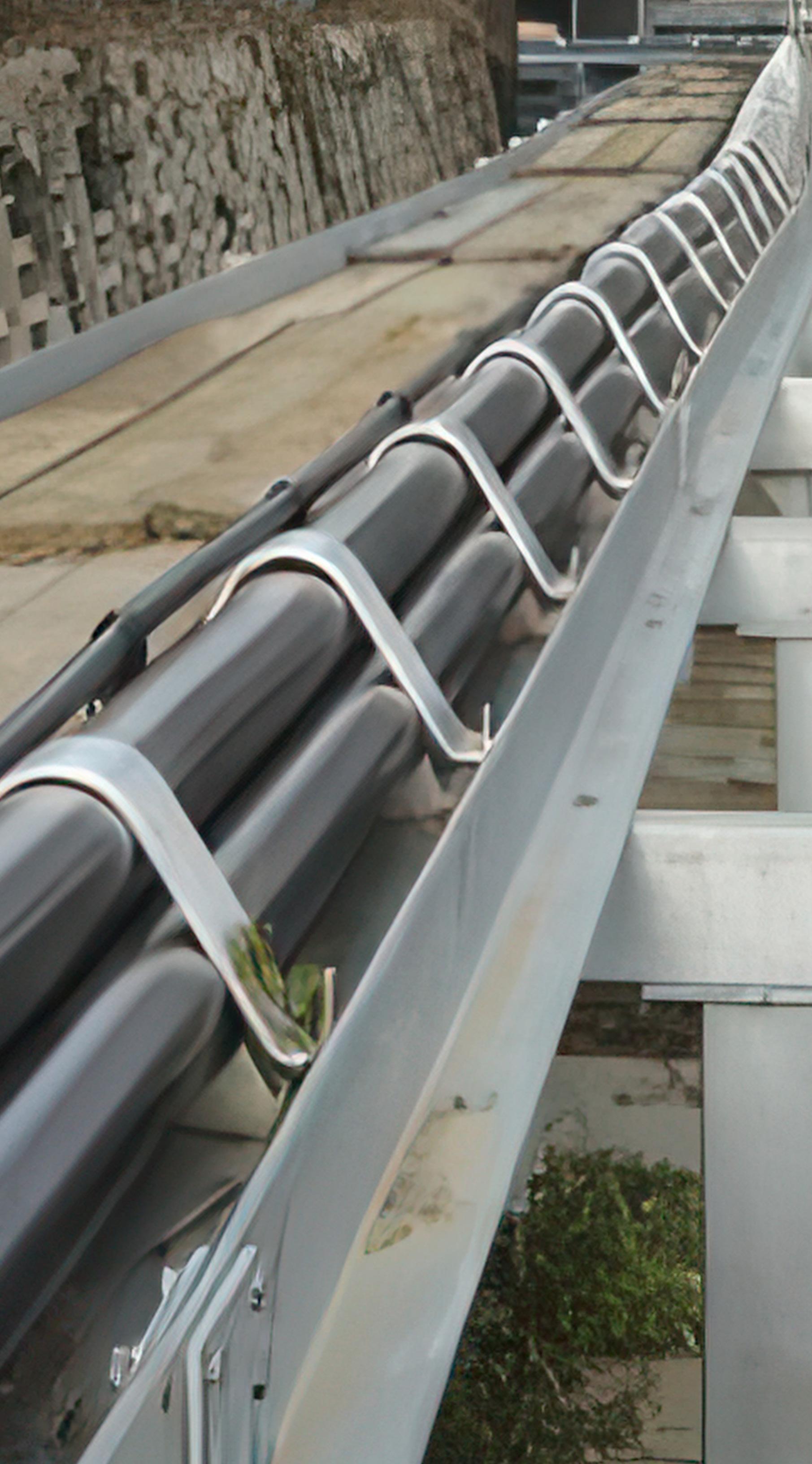
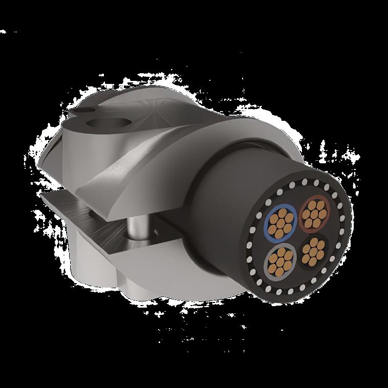
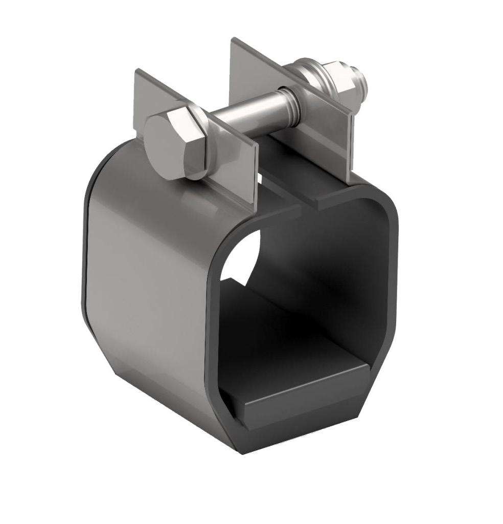
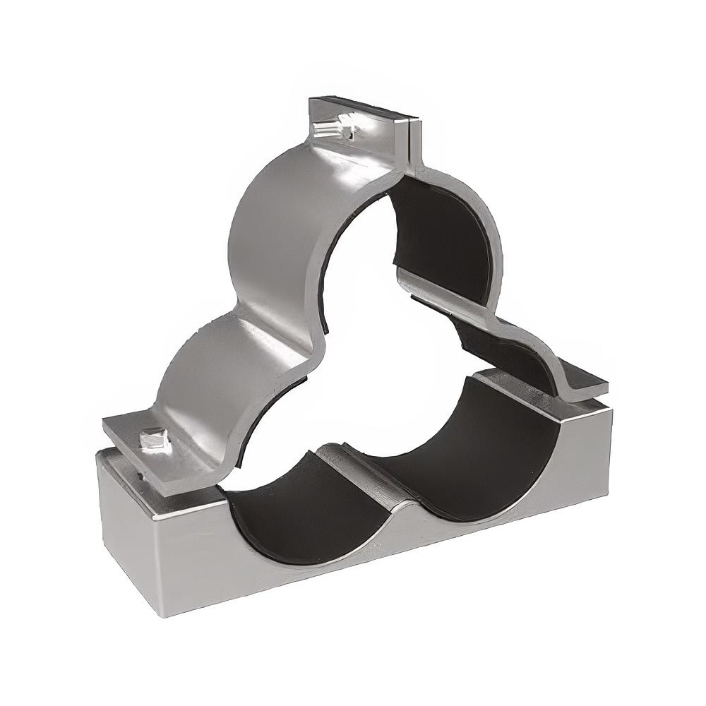


Cables can be mounted on supports in many ways, however if cable cleats are correctly used to do this they will satisfy the requirements of the IET 17th Edition Wiring Regulations.
522.8.4 “Where the conductors or cables are not supported continuously due to the method of installation, they shall be supported by suitable means at appropriate intervals in such a manner that the conductors or cables do not suffer damage by their own weight.” (1)
522.8.5 ”Every cable and conductor shall be supported in such a way that it is not exposed to undue mechanical strain and so that there is no appreciable mechanical strain on the terminations of the conductors, account being taken of the mechanical strain imposed by the supported weight of the cable or conductor itself.” (1)
Cable cleats also offer the following additional advantages:
- They facilitate a neat and orderly installation allowing cables to be used at their optimum ratings whilst maximising the use of available space.
- They maintain cables in position making reworking easier and potentially safer.
- They provide restraint against short circuit forces.
This catalogue is designed to direct you to the most suitable Prysmian Components cleat for your application.
The logic tree below shows the decisions that need to be made in order to specify the correct cleat for a specific installation.
(1) 522.8.4 , 522.8.5 extracts from BS 7671 – IET 17th edition wiring regulations

The first decision is whether or not the arrangement is a single cable or a trefoil grouping:
• When fixing a single cable the cleats should be installed in line with the IET 17th Edition – guide to use table.
• When fixing trefoil groups the controlling factor becomes the system short circuit rating and cleats should be selected and spaced according to their short circuit performance.

Spacings of supports for cables in accessible positions
Non‑armoured thermosetting, thermoplastic or lead sheathed cables and non armoured fire resisting cables.
Note:
Fire resistant fixings should be used for fire resistant cables.
* For flat cables taken as the dimension of the major axis.
The spacings shown above apply to multi-core cables.
The spacing of fixings on single core cables in a.c. installations must take account of the magnitude of forces generated under fault conditions.
† The spacings stated for horizontal runs may be applied also to runs at an angle of more than 30° from the vertical.
For runs at an angle of 30° or less from the vertical, the vertical spacings are applicable.
When a short circuit fault occurs in a three phase system, there is at first a period of extreme asymmetry which is then followed by a steadier more symmetrical state. The degree of asymmetry depends on when in the cycle the fault is initiated and also the nature of the fault, e.g. three phase to earth. By convention, the “Peak” is the maximum current value achieved in the early asymmetrical period and it is at this point that the highest instantaneous force between the cables occurs.

BS EN 61914:2009 ( IEC 61914 ) provides a formula which enables us to calculate the maximum force on a cable conductor.


is the maximum force on the cable conductor in a trefoil configuration for a three phase short circuit [N/m]
is the peak short-circuit current [kA]
is the centre to centre distance between two neighbouring conductors [m] (for Trefoil arrangements S = Cable Diameter)

Short circuit tests in accordance with BS EN 61914:2009 are performed on the most critical cleat size within its range; the Formula (B.4) can then be used to calculate the maximum force generated during the test. This maximum force figure can then be used when specifying alternative configurations of cable size and fault current – calculating the theoretical Ft for the alternative configuration and ensuring that it is less than or equal to the as tested value.
Trefoil Cleat Spacing
Trefoil cleats that are required to withstand the high forces generated by high short circuit currents will often be spaced at very regular intervals – typically matching the commonly available cable ladder (i.e. 300mm / 225mm).
The maximum short circuit current values will be quoted with the test information for each design of trefoil cleat - if a system uses larger cables or has a lower fault current it may be possible to broaden these spacings - (contact the Elpress Salesperson).
As a general rule in order to create and maintain a satisfactory trefoil installation a maximum strap/cleat spacing of 900mm is preferred.
For many years there were no British or International standards for cable cleats; Prysmian Components were actively involved in the creation of the European Standard and in progressing the standard through to it being published as the current international standard BS EN 61914:2009 (IEC 61914).
Our cleats have been tested by independent testing authorities including:
BSTS (ASTA)
ERDA (ASTA)
CPRI (ASTA)
IPH CESI (ASTA)
ZKU
We also hold third party test reports for our LSOH cleats detailing compliance with LUL requirements. Many of our cleats have Network Rail PADS approval numbers. Contact your Elpress Salesperson for more information.
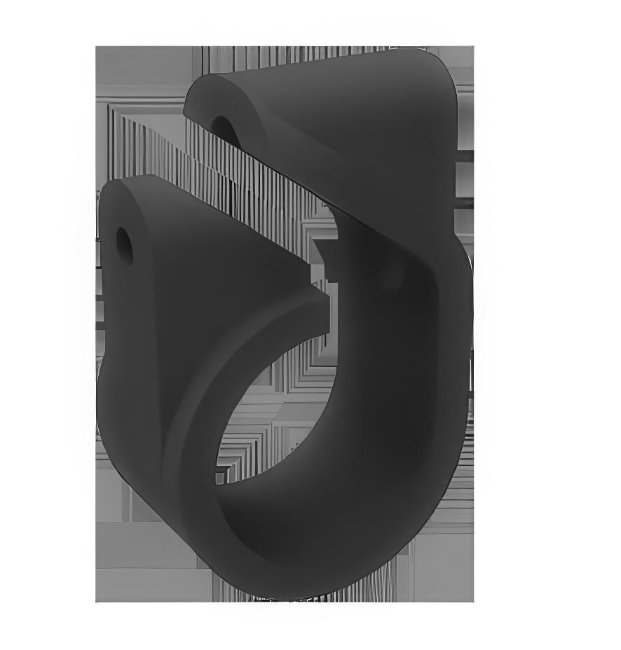
• Suitable for use with cable diameters 10 to 51mm.
• Manufactured from Low Density Polythene.
• Overlapping self-adjusting ranges.
• Sunlight (UV) and weather resistant.
• One piece, single fixing design.
• Can be double stacked on a single fixing.
• Operating temperature -40°C to +60°C.
• Tested in accordance with BS EN 50368.
The cleat is opened up and placed around the cable so that the end of the cleat containing the slot will be in contact with the mounting surface, except for the CC-385AA01, which should be reversed to put the slot uppermost. In this case an M5 washer should be used to prevent the nut entering the slot of the cleat. When mounting directly on channel section an adaptor plate should be used.
* Technical Information subject to change without notice
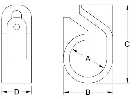

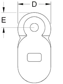
• Suitable for use with cable diameters 10 to 51mm.
• Manufactured from LSOH polymer.
• Designed for use with Afumex LSOH and Saffire OHLS cables.
• Overlapping self-adjusting ranges.
• Sunlight (UV) and weather resistant.
• One piece, single fixing design.
• Can be double stacked on a single fixing.
• Operating temperature -40ºC to +40ºC.
• Tested in accordance with BS EN 50368.
• LUL approved product register ID 1259.
The cleat is opened up and placed around the cable so that the end of the cleat containing the slot will be in contact with the mounting surface, except for the CC-385LSF01, which should be reversed to put the slot uppermost. In this case an M5 washer should be used to prevent the nut entering the slot of the cleat. When mounting directly on channel section an adaptor plate should be used
*


• Suitable for use with cable diameters 13 to 76mm.
• Overlapping, self-adjusting ranges.
• Sunlight (UV) and weather resistant.
• Made from ABS which provides good oil and chemical resistance.
• Two piece, single bolt fixing.
• Double stacking facility.
• Operating temperature -20°C to +90°C.
• ‘C’ Section channel location aids fixing and stacking.
• Not designed for long vertical runs.
Method of Fixing
In all applications the cleat should be mounted on suitable M10 fixings. There is no need for any channel adaptor when mounting directly on to ‘C’ section channel.
SWL data based upon the use of commercial grade 4.6 mild steel.
SWL = Safe working load.
FOS 2 = Values include a factor of safety of 2.


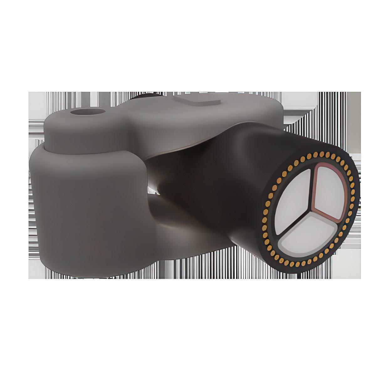
• Suitable for use with cables diameters 25 to 80mm.
• Manufactured from glass-filled nylon.
• Two-piece, single fixing design.
• Can be double stacked on a single fixing.
• Can be installed in temporary open position to aid single person working.
• All sizes secured with 10mm fixings.
• Operating temperature -25°C to +85°C.
• For normal industrial use indoor and outdoor.
• Fits most ladder and tray systems.
• Not designed to secure cables in long vertical routes.
• Tested in accordance with BS EN 50368.
Method of Fixing
In all applications the cleat should be mounted on suitable M10 fixings. There is no need for any channel adaptor when mounting directly on to ‘C’ section channel.
* Technical Information subject to change without notice


• Suitable for use with cable diameters 50 to 94mm.
• Manufactured from black high-density nylon 66.
• Unaffected by corrosive environments such as oils and many chemicals.
• Sunlight (UV) and weather resistant.
• Two-piece, two fixing design.
• Can be double stacked on common fixings.
• Operating temperature -25°C to +85°C.
• Tested in accordance with BS EN 50368.
Method of Fixing
In all applications the cleat should be mounted on suitable M10 fixings. There is no need for any channel adaptor when mounting directly on to ‘C’ section channel.
Test Standard EN 50368:2003
Load 198 -> 494 N Needle Flame >120 secs
* Technical Information subject to change without notice A B C D E


• Suitable for use with cable diameters 50 to 94mm.
• Manufactured from LSOH Polymer.
• Designed for use with Afumex LSOH and Saffire OHLS cables.
• Low Smoke and Zero Halogen.
• Sunlight (UV) and weather resistant.
• Two-piece, two fixing design.
• Can be double stacked on common fixings.
• Operating temperature -40°C to +60°C.
• Tested in accordance with BS EN 50368.
• LUL approved product register ID 1958.
Method of Fixing
In all applications the cleat should be mounted on suitable M10 fixings. There is no need for any channel adaptor when mounting directly on to ‘C’ section channel.
Test Standard EN 50368:2003
* Technical Information subject to change without notice


• Suitable for use with cable diameters 10 to 51mm.
• Manufactured from aluminium alloy.
• Two-piece, single fixing design.
• Can be stacked to a maximum of three on one fixing.
• Operating temperature -60°C to +105°C.
• Can be used for all types of cable routes.
• Plain finish - for normal industrial areas or outdoor unpolluted areas.
• Epoxy coated versions available for harsher environments.
• Packing pieces to be used where required.
• LUL approved product register ID 1959.
In all applications the cleats should be mounted on suitable M10 fixings. When mounting directly on channel, adaptor plate CC-380AG02 should be used. When stacking claw cleats use packing piece CC-389AC03 between cleats.
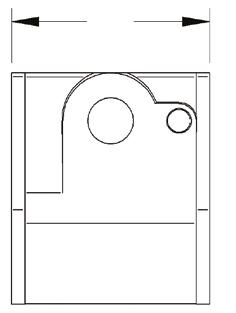


• Suitable for use with cable diameters 51 to 159mm.
• Manufactured from aluminium alloy.
• Two-piece, two fixing design.
• Can be double stacked on common fixings.
• Operating temperature -60°C to +105°C.
• Suitable for LV & HV cables.
• Can be used for all types of cable routes.
• Plain finish - for normal industrial areas or outdoor unpolluted areas.
• Epoxy Coated versions available for harsher environments.
• Optional rubber liners available.
• Tested in accordance with BS EN 50368.
• LUL approved product register ID 1963.
In all applications the cleat should be mounted on suitable fixings, see table for appropriate size. When mounting directly on channel, adapter plate CC-380AG02 should be used.

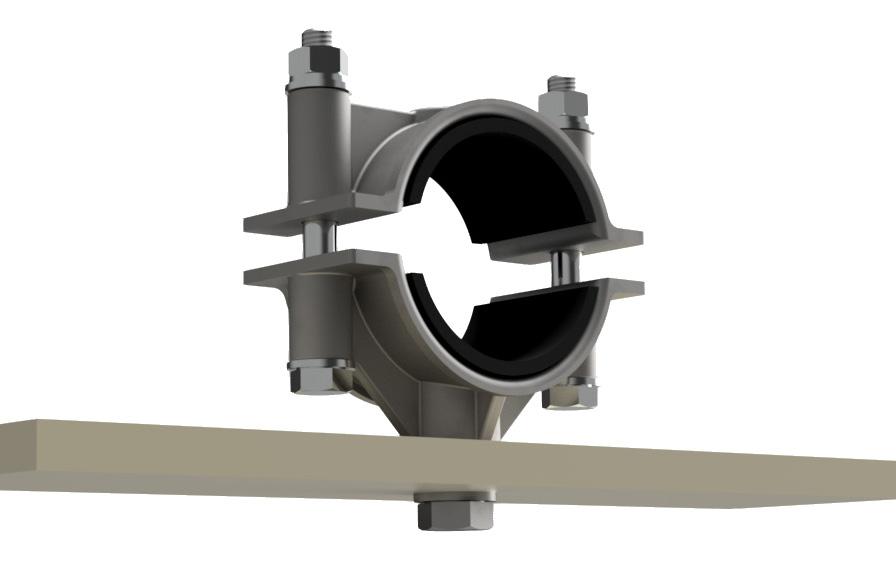
• Suitable for use with cable diameters 10 to 51mm.
• Manufactured from aluminium alloy.
• Two-piece, single fixing design.
• Can be stacked to a maximum of three on one fixing.
• Operating temperature -60°C to +105°C.
• Can be used for all types of cable routes.
• Plain finish - for normal industrial areas or outdoor unpolluted areas.
• Epoxy coated versions available for harsher environments.
• Packing pieces to be used where required.
• LUL approved product register ID 1959.
Technical Data
Performance Data
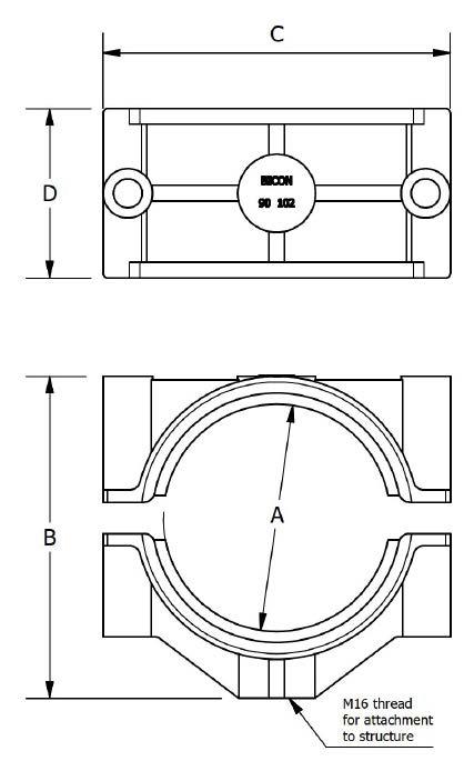
Technical Information subject to change without notice


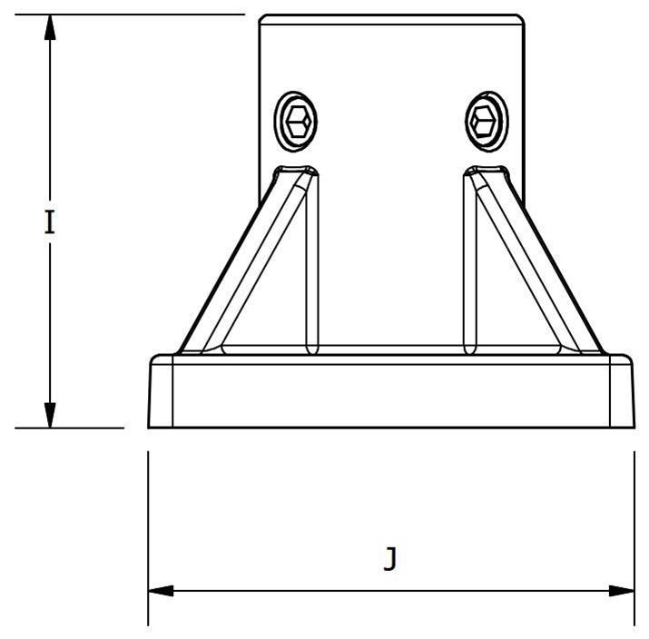


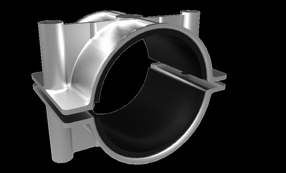

• Suitable for use with cable diameters 16 to 149mm.
• Manufactured from aluminium alloy.
• Sizes 05-09 - Two piece, single fixing claw design.
• Sizes 10-36 - Two piece, two fixing design.
• Can be double stacked on common fixings.
• Operating temperature -60°C to +105°C.
• Suitable for LV & HV cables.
• Can be used for all types of cable routes.
• Plain finish - for normal industrial areas or outdoor unpolluted areas.
• Epoxy coated versions available for harsh environments.
• Tested in accordance with BS EN 50368.
• LUL approved product register ID 1963.


CC-370BA16SL
In order to allow for the linear expansion of larger cables the support positions are often broadly spaced. Such broad spacing would put very high point loading on the cables which could lead to long term failure. The shoe cleats are designed to allow this potentially damaging load to be spread over a significantly longer length thus avoiding any potential cable damage. Based on the 370 series of aluminium 2 bolt cleats with the shoes made from 316L stainless steel with rubber lining. The shoes are designed and formed with the correct bend radius to match the cable’s expansion curve.
Contact your Elpress Salesperson who will be able to match the correct cleat and spacing to the size of cable and installation design.
* Technical Information subject to change without notice

The linear short circuit straps can be used in horizontal or vertical installations. They can be designed and manufactured to user specified interaxial spacings. Options are available for them to be supplied with or without rubber liners to meet the cable system design requirements.
Contact your Elpress Salesperson who will be able to match the correct cleat and spacing to the size of cable and installation design.
Note
Replace ‘xxx’ with 300, 400, 500, 600, 700 for required cable separation.

• Ideally suitable for larger cables with diameters 100 to 159 mm.
• Manufactured from aluminium alloy.
• Two-piece, two fixing design.
• Operating temperature -60°C to +105°C.
• Designed to protect the cable sheaths during installation.
• Plain finish - for normal industrial areas or outdoor unpolluted areas.
• Epoxy coated versions available for harsher environments.
• Supplied with rubber liners.
• Tested in accordance with BS EN 61914.
• Spring loaded version available upon request.
Cable
Lateral Load 50 kN
Axial Load 8kN
Needle Flame >120 secs
* Technical Information subject to change without notice


• Suitable for use with cable diameters 33 to 150mm.
• Single bolt fixing with reversible base for range taking.
• Operating temperatures -40°C to +120°C.
• Ergonomic design allows easy installation, with single tool tightening from the top side.
• Manufactured from non-magnetic, corrosion resistant 316L stainless steel.
• Liners are made from LSOH materials.
• Suitable for use with single and multicore cables with high fault current requirements.
• Suitable for standard and LSOH cable sheaths.
• Can be used in harsh environments.
• Can be used with all standard ladder and tray systems.
• Complies with BS EN 61914.

*
Information subject to change without notice
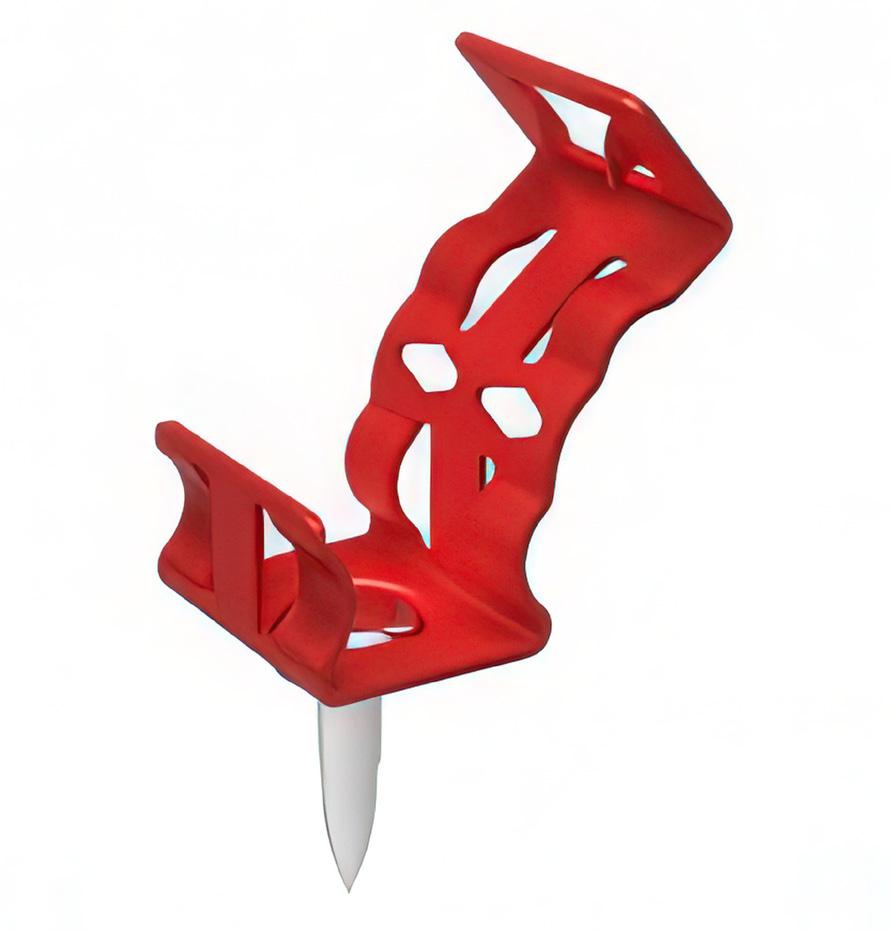
• LUL Approved product register ID 1960.
• Nail fixed fire resistant clip.
• The Firefix™ system is fast easy and meets the cable support requirements of British standards: BS5839-1: 2002, BS5266-1:2011 and BS5839-8: 2006.
• Designed to be used with the Spit Pulsa™ gas nailing technology for rapid installation.
• Made from corrosion resistant stainless steel which is coated with an intumescent LSOH coating in either white or red to match the cable.
• Should be installed in accordance with BS7671 / IEE wiring regulations, or other appropriate code.
• Can be fixed to steel, block work, composite steel decking, brick or concrete.
• The fixing of the clip and installation of the cable takes just 10 sec.
* Not supplied
1. Position the FIREFIX™ clip directly on to the nail guide 2. (No adaptors required).
3. Ensure the substrate is clear before pushing the Spit Pulsa™ tool against the substrate, and nailing the clip into position.
4. Place the cable into the clip.
5. Close clip.


• LUL Approved product register ID 1960.
• Nail fixed fire resistant clip.
• The Firefix™ system is fast easy and meets the cable support requirements of British standards: BS5839-1: 2002, BS5266-1:2011 and BS5839-8: 2006.
• Designed to be used with the Spit Pulsa™ gas nailing technology for rapid installation.
• Made from corrosion resistant stainless steel which is coated with an intumescent LSOH coating in either white or red to match the cable.
• Should be installed in accordance with BS7671 / IEE wiring regulations, or other appropriate code.
• Can be fixed to steel, block work, composite steel decking, brick or concrete.
• The fixing of the clip and installation of the cable takes just 10 sec.
* Not supplied
Nailing tool sold separately. Part No: PULSA800E
Installation
1. Attach adaptor to Pulsa™ tool.
2. Position the FIREFIX™ clip on to the adaptor.
3. Ensure the substrate is clear before pushing the Spit Pulsa™ tool against the substrate, and nailing the clip into position.
4. Place the cable into the clip.
5. Close clip.


• Suitable for Prysmian FP200 Gold®, FP Plus™, FP Plus Flex™ and Afumex LSX™.
• Suitable for Draka FT30, FT120 and FT Data.
• Securely holds one cable - ideal for a single cable run.
• Made from BS EN 1652 copper strip.
• Fire tested with FP cables.
• Finished with a red or white LSOH polyester coating.
• Ideal for visible installations.
• Meets the cable support requirements of BS 5839-1:2002+A2:2008.


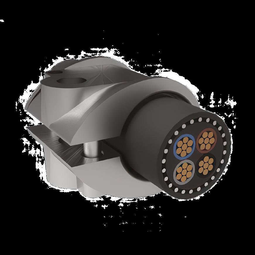
• Suitable for use with cable diameters 10 - 54mm.
• Hot dip galvanised finish on cast iron.
• Two-piece, single fixing design.
• Can be stacked to a maximum of three on one fixing.
• Operating temperature -60ºC to +105ºC.
• Can withstand a 2 hour excursion to 1000ºC.
• Can be used for all types of cable routes.
• Suitable for all environments.
• Packing pieces to be used where required.
• LUL Approved product register ID 1961.
• Allows fire performance cables to meet the requirements of BS 6387:1994, BS 5839-1:2002, BS7346-6:2005 & BS8491:2008.
In all applications the cleats should be mounted on suitable fixings, see table for appropriate size. When mounting directly on channel, adaptor plates CC-380AG02 should be used. When stacking claw cleats use packing piece CC-389AC01 between cleats.
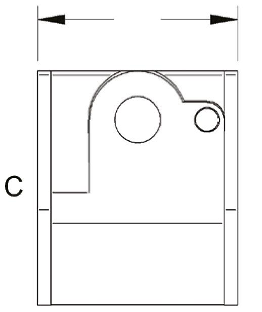


• Suitable for use with cable diameters 51 - 89mm.
• Hot dip galvanised finish on cast iron.
• Two-piece, two fixing design.
• Can be double stacked on common fixings.
• Operating temperature -60°C to +105°C.
• Can withstand a 2 hour excursion to 1000°C.
• Can be used for all types of cable routes.
• Suitable for all environments.
• LUL Approved product register ID 1964.
• Allows fire performance cables to meet the requirements of BS 6387:1994, BS 5839-1:2002, BS7346-6:2005 & BS8491:2008.
In all applications the cleats should be mounted on suitable fixings, see table for appropriate size. When mounting directly on channel, adaptor plate CC-380AG02 should be used.


• Meets the requirements of BS EN 61914:2016 & IEC 61914:2015.
• Suitable for use with cable diameters 20 to 70mm.
• Single or double bolt fixing.
• Operating temperatures -40°C to +60°C.
• Manufactured from non-magnetic, corrosion resistant 316L stainless steel.
• Liners are made from LSOH materials to compliment the cable sheath.
• Suitable for single core cables laid in quad formation.
• Suitable for standard and LSOH cable sheaths.
• Designed to be used in most environments.
• Suitable for use with all standard ladder and tray systems
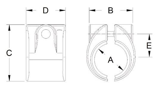
All cleats have a single central fixing hole for a 10mm diameter fixing bolt. Styles 05 to 10 can also be fixed with 2 x 10mm bolts - the 10mm clearance holes are positioned either side of the central hole with centres as per dimension D.
* Technical Information subject to change without notice


• Suitable for use with cable diameters 24 to 145mm.
• Large range take on each size.
• Single or double bolt fixing.
• Operating temperatures -60°C to +105°C.
• All straps manufactured from non-magnetic 316L stainless steel.
• Plain aluminium bases - for normal industrial areas or outdoorunpolluted areas.
• Epoxy coated aluminium versions or stainless steel available for harsher environments.
• Bespoke tensioning adaptor included with every cleat and strap.
• Cleats and Straps are supplied with LSOH liners as standard.

• Suitable for single core cables laid in trefoil formation with high fault current capacities.
• Suitable for use with all standard ladder and tray systems.
• Suitable for groups of dissimilar cables.
• LUL Approved product register ID 1996.


Fasten base (Item 1) to the support structure with the recommended fixings and lay the cable(s) (Item 2) on the base.
Feed 1 loop of the strap (Item 3) through the base and around cables, then cut the LSF liner into 2 pieces (Item 4a & 4b) and fit underneath the strap.

Remove the nut and lock washer from the winder assembly (Item 5). Then fit winder assembly into the buckle on the strap (Item 3) by sliding the split pin of winder assembly through the smaller hole, then fitting the thread of the assembly through the larger hole. Put the lock washer and nut back onto the thread of the winder assembly.

Continue to wind the strap (Item 3)around the cables. Standard duty = 2 loops Heavy duty = 3 loops. Feed the end of the strap through the split pin of the winder assembly (Item 5) until approximately 10mm of strap is protruding through the pin. To tension the strap, push a plastic winder (Item 6) onto the end of the split pin and use a 13mm socket to rotate the split pin clockwise until the strap is tight. Adjust strap and liner to maintain buckle position during tightening. Ensure all layers of the strap are secured within the LSF liner (Item 4). Once strap is tightened, use a 17mm spanner to hold the winder hex to prevent the strap from loosening.

Whilst maintaining the strap tightness with the spanner, use the 13mm socket to tighten the lock nut. Torque to 25Nm. Once torque is applied, assembly is complete.
Example ordering code: 378 AD 58 Multicleat.
Important note: To ensure adequate restraint, Multistrap MUST be used at the mid-point between cleats on all horizontal and vertical straight runs.

Horizontal changes in direction, restraint spacing of 300mm maximum. Use Multistrap and / or Multicleat, as appropriate, to suit the support structure.
Note: Bases should be fixed with one or two M10 fixings as appropriate.


all applications

• Suitable for use with cable diameters 23 to 128mm.
• Single or double bolt fixing with reversible base for range taking
• Operating temperatures -40°C to +120°C.
• Ergonomic design allows easy installation, with single tool tightening from the top side.
• Manufactured from non-magnetic, corrosion resistant 316L stainless steel.
• Liners are made from LSOH materials.
• Suitable for single core cables laid in trefoil formation with high fault current requirements.
• Suitable for standard and LSOH cable sheaths.
• Can be used in harsh environments.
• Suitable for use with all standard ladder and tray systems.
and Cleat Selection
• Complies with BS EN 61914. All cleats have a single central fixing hole for a 12mm diameter fixing bolt. Styles 02 to 22 can be also fixed with 2 x 10mm bolts - the 10mm clearance holes are positioned either side of the central hole with centres as per dimension D.

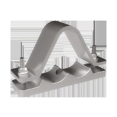
• Suitable for use with cable diameters 62-186mm.
• Manufactured from aluminium alloy.
• Suitable for use on LV, MV & HV cable designs.
• Single or two bolt fixing.
• Designed for use with larger diameter single core cables laid in trefoil formation.
• Deep section cast bases aid cable installation.
• Can be supplied with rubber liners.
• Profiled versions are available to meet specific design requirements.
• Tested in accordance with EN 50368:2003.


• Manufactured from aluminium alloy.
• Suitable for single core cables laid in trefoil.
• Can be used with all types of cable routes.
• Supplied complete with top fastening.
• Operating temperature -60°C to +100°C.
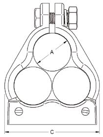

• Epoxy coated for harsher more hostile conditions.
• Suitable for use with cable diameters 24 to 76mm.
• Plain finish for indoor dry normal industrial use or outdoor unpolluted areas.
• Suitable for use at a maximum system fault level of 30kA rms.

• Manufactured from 316L stainless steel.
• Includes rubber liner.
• Used in conjunction with the 376 Orion and 376 Orion-shaped cleats.

• Made from 316L stainless steel.
• Comes with LSOH liners.
• Profiled to aid easy and quick installation.
• Single bolt closing.
• Used in conjunction with the 379 Sirius cleats.
Resistance to 6.4.4 (2 short circuit) 56.8kA rms, 125kA peak, Short Circuit Ø36mm, Spacing 300mm in conjunction with 379TC Sirius cleats.
* Technical Information subject to change without notice


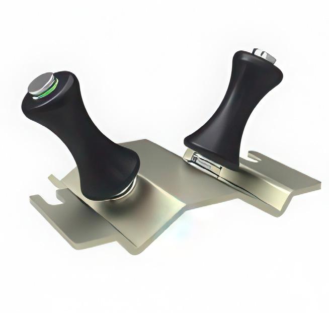
Designed with the same fixing arrangements as the 2 bolt and Shoe cleats. The rollers and lifting jacks facilitate cable system Installation. The rollers can be configured in a variety of different ways – please speak to Elpress Salesperson for more information.

An innovative solution for the retrofitting of damaged cleats on old cables that cannot be moved. These custom-made retrofitting cleats can be provided on a rapid turnaround. These can be supplied with adjustable elements to overcome onsite variables.
Used to secure an auxiliary cable along the same route as an existing cable installation. Secured by the multi-strap system, the stand-off arrangement is made from a tough LSOH polymer. Used with rubber liners.
The Multicleat / Multistrap system is ideally suited for securing groups of cables of differing sizes. Your Elpress Sales person will be able to match the correct cleat /strap to the size and fault rating of the cable arrangement.
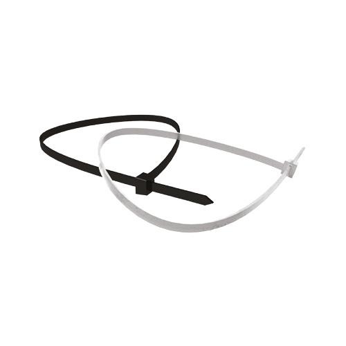
Bundles of cables up to 100mm in diameter. Available in black or natural finish. Operating temperatures -40°C to +85°C.
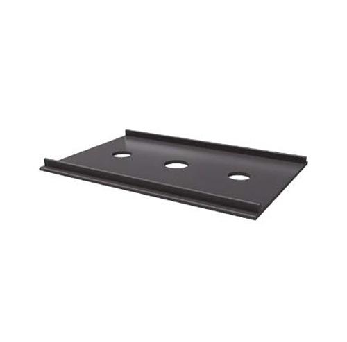
Insulating pad
Insulating pads are designed for use with the 379 series Sirius and Orbit cleats. They are designed to prevent bimetalic corrosion between the cleat and the substructure. They should be used in instances when installing a stainless steel cleat onto a galvanised steel substructure.
Suitable

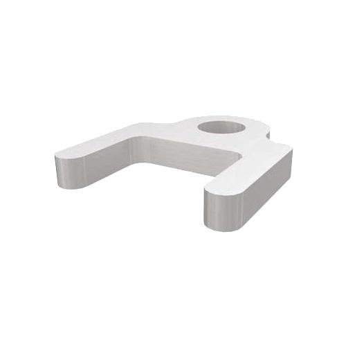
Required when mounting smaller cleats directly onto 41mm wide channel.
Adaptor Plate
Required when stacking claw cleats.

We have been developing, manufacturing and marketing complete crimping systems for electrical connectors since 1959.
The Elpress Group consists of the Elpress and ABIKO business areas and is owned by Lagercrantz Group AB. Elpress head office, factory and warehouse are located in Kramfors, Sweden.
Subsidiaries Elpress GmbH, Elpress A/S, Elpress AS, Elpress (Beijing) Ltd. and Elpress Inc. with local warehouses in Silkeborg/Denmark, Beijing/China and Chicago/USA.
Elpress AB . P.O. Box 186, SE-872 24 KRAMFORS, Sweden Tel: +46 612-71 71 00 sales@elpress.se | www.elpress.net
Elpress A/S . Randersvej 16, DK-8600 Silkeborg, Danmark Tel: +45 86 81 61 11 salg@elpress.dk | www.elpress.dk
Elpress AS . Bruket 31, Pb 79, N-1621 Gressvik, Norge Tlf.: +47 91 68 55 02 sales@elpress.no | www.elpress.no
Elpress INC. 1 E 22nd Street, Suite 200, Lombard IL. 60148 USA Tel: +1-331-814 2910 sales@elpress.us | www.elpress.us
Elpress GmbH . Kränkelsweg 24, DE-41748 VIERSEN, Deutschland Tel: +49 2162 93 19-0 sales@elpress.de | www.elpress.de
ELPRESS(北京)电器元件有限公司 北京市朝阳区东三环北路H2号城融大厦605室, 100027 +86 10 597 961 87 info@elpress.com.cn | www.elpress.com.cn
www.elpress.net