Appendix A • Common audio connectors and pinouts
Appendix A • Common audio connectors and pinouts
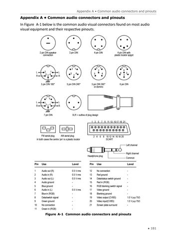
In Figure A-1 below is the common audio visual connectors found on most audio visual equipment and their respective pinouts.
2 pin DIN speaker connection
L R
3 1 524
3 pin DIN
L R
5 pin DIN 180°
7
L R
3
4 pin DIN
3
3 1 5
2
4
5 pin DIN 240°
5
2
4 pin DIN with plastic locator spigot
5
1 4
5 pin DIN 360° or domino
4
6 3
1 2
6 pin DIN
6
52 4
1
7 pin DIN
L R XLR + outline of plug design 1 3 5 7 9 11 13 15 17 19 21
FM aerial plug AM aerial plug In both cases the centre ‘pin’ is a plastic locator
2 4 6 8 10 12 14 16 18 20 SCART Left channel
Headphone plug
Right channel Common
Pin
Use
Level
Pin
Use
Level
1 2
Audio out (R) Audio in (R)
0.5 V rms 0.5 V rms
12 13
No connection Red ground
-
3
Audio out (L)
0.5 V rms
14
Data/status switch ground
-
4 5 6
Audio ground Blue ground Audio in (L)
0.5 V rms
15 16 17
Red in (RGB) RGB blanking switch signal Video ground
-
7
Blue in (RGB)
-
18
Blanking ground
-
8 9 10
Data/switch signal Green ground No connection
-
19 20 21
Video output (CVBS) Video input(CVBS) Screen plate surround
1.0 V p-p 75Ω 1.0 V p-p 75Ω -
11
Green in (RGB)
-
Figure A-1 Common audio connectors and pinouts
● 181