ESP32 by Example
A Project-Based Introduction to Microcontrollers and Drone Control


Academy Pro Title by Jim
Solderitsch


Academy Pro Title by Jim
Solderitsch
Jim Solderitsch
● This is an Elektor Publication. Elektor is the media brand of Elektor International Media B.V. PO Box 11, NL-6114-ZG Susteren, The Netherlands Phone: +31 46 4389444
● All rights reserved. No part of this book may be reproduced in any material form, including photocopying, or storing in any medium by electronic means and whether or not transiently or incidentally to some other use of this publication, without the written permission of the copyright holder except in accordance with the provisions of the Copyright Designs and Patents Act 1988 or under the terms of a licence issued by the Copyright Licencing Agency Ltd., 90 Tottenham Court Road, London, England W1P 9HE. Applications for the copyright holder's permission to reproduce any part of the publication should be addressed to the publishers.
● Declaration
The author and publisher have made every effort to ensure the accuracy of the information contained in this book. They do not assume, or hereby disclaim, any liability to any party for any loss or damage caused by errors or omissions in this book, whether such errors or omissions result from negligence, accident, or any other cause. The author expresses his sincere gratitude to Arrow Electronics and Trenz Electronic for granting permission to include various tables, figures, and program codes in this book.
● ISBN 978-3-89576-670-1 Print
ISBN 978-3-89576-671-8 eBook
● © Copyright 2025 Elektor International Media www.elektor.com
Editor: Clemens Valens
Prepress Production: D-Vision, Julian van den Berg Printers: Ipskamp, Enschede, The Netherlands
Elektor is the world's leading source of essential technical information and electronics products for pro engineers, electronics designers, and the companies seeking to engage them. Each day, our international team develops and delivers high-quality content - via a variety of media channels (including magazines, video, digital media, and social media) in several languages - relating to electronics design and DIY electronics. www.elektormagazine.com
1.1 What this book is about
This book is for you if you have become aware of the world of embedded systems and microcontrollers and want a place and an approach to get started. Perhaps you've considered general purpose microelectronics books and courses like those beginning with Arduino hardware and boards, but they seem too general purpose and lack interesting projects and examples. You want to start at the beginning to learn how to be successful but want the learning pace to be stimulating and interactive.
In this book, I expect that you are comfortable with a no fluff/just stuff approach. You embrace an example driven approach. You are comfortable with hands on learning, and you can assemble the ESP32 by Example Kit (EEK) circuit hardware, test it after assembly and then reuse it, pretty much as-is, for the rest of the course. There will be no need to connect and disconnect for each new lesson or example. The book provides detailed assembly guidance in chapter four of the book.
I expect that you want to learn to adapt and extend the book examples to support your own ideas and applications and that you want to build something substantial with a practical application. The EEK (ESP32 by Example Kit) as a drone controller is one such application.
Through this book the acronym EEK: ESP32 by Example Kit will be used regularly to refer to what you will build and what you will learn with. It is more than just the ESP32 Micro Controller Unit (MCU) itself. There are many varieties of ESP32s on the market and this book will cover two of them in depth. Some other versions are discussed in chapter 3 Compatible Boards and with a little bit of investigation you could substitute any of these for your projects. But the EEK is more than the MCU; it is also a collection of parts including LEDs, resistors, push button switches, an OLED display and a Multi-Processor Unit (MPU) that contains an accelerometer and gyroscope. We assemble these parts into a working circuit board and encounter a wide variety of examples and projects where you learn how to apply the EEK to solve problems and derive value. When you see the EEK acronym used, I want you to think of this larger environmental context.
The learning approach followed in this book is designed to include just enough hardware elements that when combined, implement and demonstrate interesting applications. You don't have to buy additional parts to complete the exercises included in the book. The book assumes minimal programming experience and no Arduino background. Some programming and Arduino background is useful, but not necessary, since there will be many examples.
You will learn by reading, executing and extending the examples that are provided, especially the mini projects that end each technical section. The book covers, and Part one requires, no other MCU (Micro Controller Unit) platforms besides the ESP32, like basic
Arduino hardware. If you want more basic Arduino content, you can look for other sources that cover such material.
Key concepts and technologies that are basic to this book are:
• ESP32
• Arduino IDE
• Cyber-Physical control including Drones
I picked the ESP32 family of MCUs because of the features included in the basic development board realizations of the ESP32 and their low cost. Features include wireless communication capabilities such as WiFi and Bluetooth. Some models also have direct connection support for battery power. Chapter 3 Compatible Boards will cover specific models and form factors that were considered.
Background information about the ESP32 can be found on the Espressif ESP32 page: https://www.espressif.com/en/products/socs/esp32. There are multiple cloned versions of the ESP32 available and some of them are very inexpensive. New versions of the ESP32 appear from time to time and software that worked with older versions may not work with newer ones. So, it's best to choose an ESP32 considered for this course such as the one in section 3.2 Feather Huzzah.
You need a process by which you write code for the ESP32, compile it, and push it to the ESP32 where it can be executed providing the Cyber-Physical effects that you want to achieve. The ESP32 supports several programming mechanisms and while the Arduino tool chain was not developed with the ESP32 in mind, Espressif has taken steps to allow the Arduino IDE (Integrated Development Environment) to be used productively. Until Part two when some Python integration will be explored, Arduino will be the only approach we will use in this book.
Some basic internet searching can provide background on the Arduino community. The link: https://www.arduino.cc/en/Guide/Introduction includes the following introductory paragraph:
Arduino is an open-source electronics platform based on easy-to-use hardware and software. Arduino boards are able to read inputs - light on a sensor, a finger on a button, or a Twitter message - and turn it into an output - activating a motor, turning on an LED, publishing something online. You can tell your board what to do by sending a set of instructions to the microcontroller on the board. To do so you use the Arduino programming language (based on Wiring), and the Arduino Software (IDE), based on Processing.
To use the IDE, it must be installed on your computer. This is covered in chapter 2 Arduino Setup. We will learn much about how the IDE is used to develop and deploy software to the ESP32.
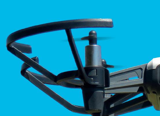
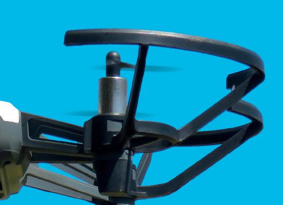
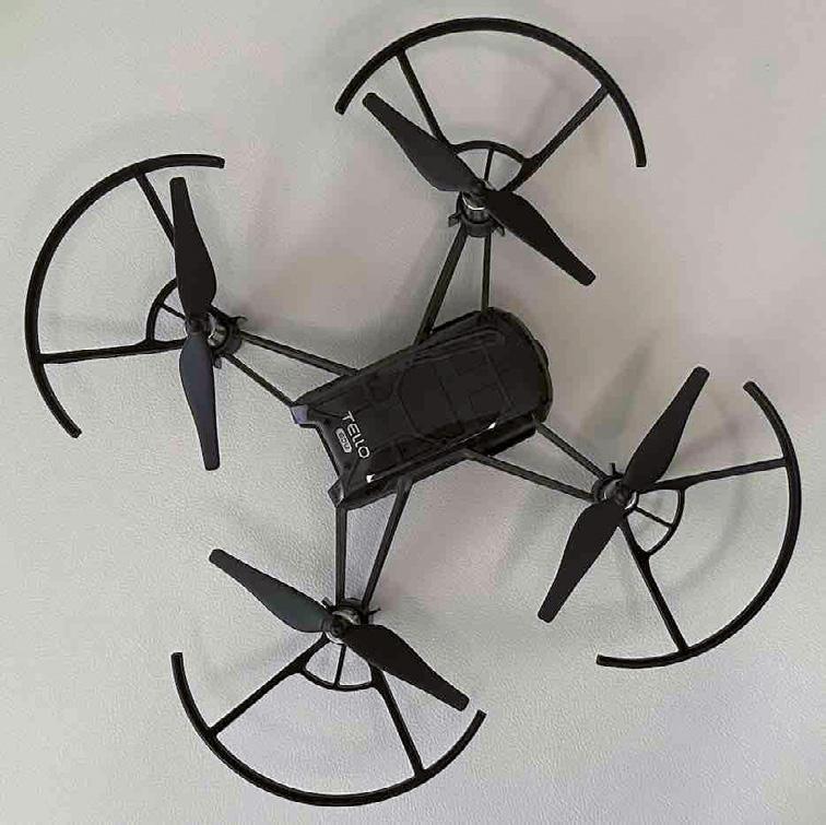
While Part one of the book covers the basics of the ESP32 and connection to various circuit elements including those contained in the EEK, I want to provide a larger Cyber-Physical context to inspire you to build useful projects combining hardware and software. For the last several years, including the months spent writing this book, educational drones have provided a a fertile playground. Until recently, the Tello drone (see Figure 1.3) was the primary drone used. A basic introduction to the Tello can be found at the company site: https://www.ryzerobotics.com/tello. Ryze is a subsidiary of the DJI corporation, which until recently was directly supporting educational applications of the Tello and related projects as discussed at the link https://www.dji.com/products/steam.
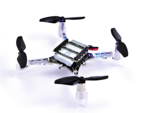
Recent publicity suggests that DJI is withdrawing from this STEAM focus, at least for the immediate future. Other drone platforms are being evaluated as this book is being written including the CrazyFlie developed and sold by the company bitcraze. The company DroneBlocks is switching from the Tello to a CrazyFlie based educational program as described at the link https://droneblocks.io/future-of-stem-education-with-crazyflie-aleap-forward-in-classroom-drone-coding/
Here is a picture of a CrazyFlie from a bitcraze store link:
For now, the Tello remains available in limited quantities and in Part two of the book the Tello is still planned as a key exemplar that will be used to introduce and cover drone control. Another possibility is to switch to a Drone Simulation approach, and I am pursuing a deeper connection with DroneBlocks that offers simulation as part of its educational process and approach.1
1 As the drone education space evolves, drone products covered here may change.
You see below a picture of an assembled EEK breadboard. Yours will look like this if you follow along with the assembly instructions.
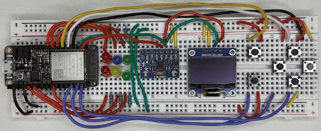
Part two of the book considerably expands on the concepts, examples and exercises presented in Part one. There is an emphasis on Cyber-Physical context and essential controls and effects leading eventually to the ability to control drone flight with no phone app or commercial controller. Part two of the book will include other physical MCUs and/or drones like a Tello to expand the cyber physical context even more. The book will show how to connect other sensors and actuators to the EEK and support other IoT simulations such as home environmental monitoring and fall detection.
My Tello EDU model is shown in Figure 1.3. The EEK covered in Part one can control any of the Tello models.
If you don't want to acquire a real drone, Part two of the course also covers the assembly of a second board, as shown in the next image, that serves as a very basic version of a drone simulator. The clear LEDs light according to which flight control actions you take with the
EEK controller from Part one, including gamepad controls like joystick motions or button presses when a gamepad is connected to the EEK. The OLED (Organic Light Emitting Diode) display echoes the flight commands received.

Outline of EEK Part one.
1. EEK introduction
- This section, including coverage of needed software, hardware and EEK parts sourcing advice and availability of an all-inclusive EEK hardware kit
2. Arduino IDE setup for the course
- The latest Arduino IDE will be used throughout the course
- Some extra steps are needed after installation to add support for ESP32 programming
3. Survey of ESP32 boards and their compatibility with EEK.
- Two ESP32 dev boards are fully supported: ESP32 DevKit Board and Adafruit Feather Huzzah with included LiPo (Lithium Polymer) battery
4. EEK breadboard assembly
- Detailed instructions are provided in the EEK Assembly chapter to complete EEK breadboard construction and test after assembly
- Fully assembled PCB (Printed Circuit Board) versions of EEK are also available.
5. EEK Basics: hardware components and examples
- Step by step coverage of the LED (Light Emitting Diode) array and pushbutton controls
- OLED display setup and usage and integration with LEDs and buttons
- MPU 6050 library support and applications that respond to breadboard gestures based on integrated accelerometer and gyroscope data
- Most EEK Basics lessons end with mini projects.
- Capstone mini project brings together most of the material covered.
6. EEK Wi-Fi
- Explore both WiFi server and client connections and applications
- Prepare and operate Simple WiFi server on ESP32
- Use WiFi-Manager Arduino library to protect Access Point connection credentials
- Define a UDP server that receives and processes UDP (User Datagram Protocol) network packets
- The Tello drone acts like a UDP server and processes flight command UDP packets, which is explored in EEK Part 2
7. EEK Bluetooth and gamepad integration
- PS4, Xbox and Android controllers are known to work
- Bluepad32 board definition needed to interact with gamepads
- Final Part 1 capstone Mini Project demonstrates EEK and gamepad interaction: receiving Joystick and d-pad data and translating the data into EEK board actions and effects
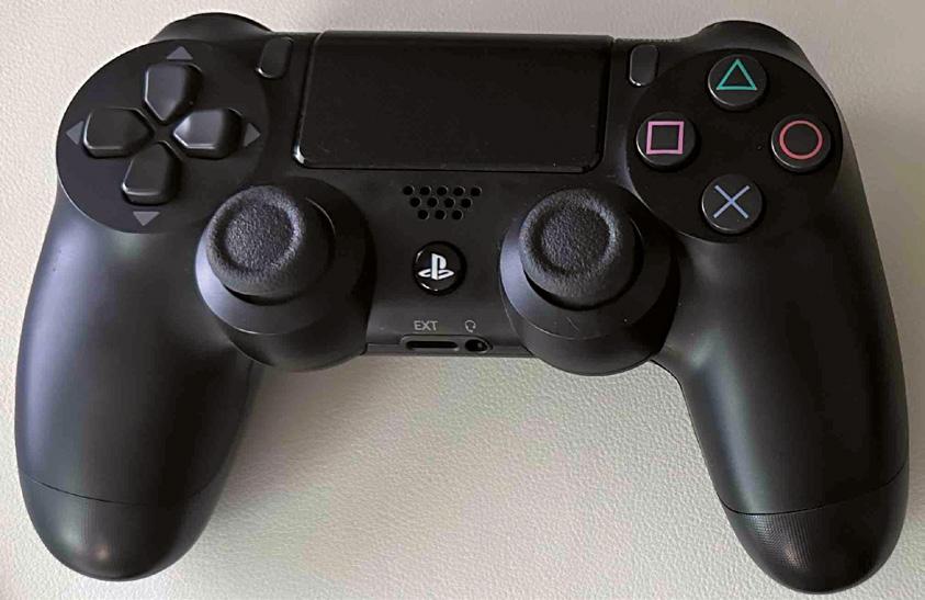
One of my PS4 game controllers is shown in the image below. Multiple varieties of video game wireless controllers can be connected to the EEK hardware. In Part two of the course, you will learn how they can be used to fly a drone or interact with the drone simulator.
Windows or Mac Computer
While writing this book I used Windows 10, Windows 11, Mac OS Ventura and Mac OS Sonoma. I prefer the Mac experience over Windows, but all the examples have been fully tested under both Mac and Windows environments.
A Linux computer may also work since the Arduino IDE (integrated Development Environment) is fully supported there but this has not been tested.
Latest version of Arduino IDE
Versions 2.2.1 through 2.3.4 of the IDE were used primarily during program development while the EEK was being defined and tested. The latest version of the IDE at the time of writing is Version 2.3.4 and there have, so far, been no differences seen when examples are compiled and executed. By the time the book is available to readers, it is expected that newer versions of the IDE will have replaced the version 2.3.4.
Arduino Install Instructions are found here:
https://docs.arduino.cc/software/ide-v2/tutorials/getting-started/ide-v2downloading-and-installing
The starting point for the IDE installation is shown in the following screenshot:

Figure 1.6 IDE Installation
USB serial cable compatible with your ESP32 board
Included in EEK kit; Android data-certified phone cable should work
Updated drivers for USB serial cable support may be needed on Windows depending on your version of Windows. This subject is covered online by several different technical writers.
PacketSender app for UDP network testing
Full usage of the PacketSender app is covered in the EEK and WiFI chapter of this book. It is used for UDP (User Datagram Protocol) wireless packet testing. An ordinary web browser like Chrome or Firefox is sufficient for TCP (Transmission Control Protocol)/IP network testing.
Information on PacketSender is available in the PacketSender homepage: https://packetsender.com/
The discussion included here on needed host computer resources is just a brief overview. The complete install of the Arduino IDE and enabling ESP32 readiness within the IDE is covered in Chapter 2: Arduino Setup.
EEK Hardware
A summary view of the EEK hardware including 2 fully supported ESP32 processor boards is shown in the following image:
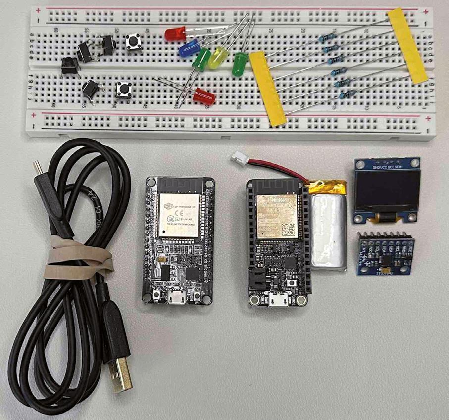
As shown in the picture, the following components are needed:
• Breadboard
- Cheap breadboards sometimes suffer from intermittent connectivity
• USB Serial Cable
- Compatible with ESP32 supporting both power supply and data communication
• ESP32 board
- LiPo Battery (Optional)
• 6 push button switches
• 6 LEDs
- LED leads must be trimmed with wire cutter
• 6 330-ohm resistors
- Resistor wires must be trimmed with wire cutter
• OLED display (SSD1306 compatible)
• MPU 6050: accelerometer and gyroscope
• Connecting wires sized to useful lengths (wires not shown in picture)
- You can use a spool of wire and a good wire stripper
- You can also get pre-cut wire
- Jumper wires with metal pins and plastic handles often used with beginner breadboard projects are NOT recommended
Both Huzzah and Dev boards are shown in the summary view. Only one is required. The Dev boards tend to be significantly cheaper than the Adafruit Huzzah, but the Huzzah comes with a LiPo battery connector.
Kit LEDs and resistors will not come pre-trimmed and need to be trimmed for clean mounting to the EEK breadboard.
Useful tools for assembly
Some tools useful for EEK assembly are shown in this picture:
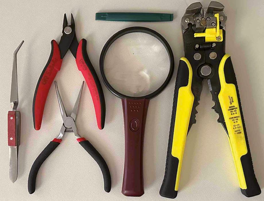
• Tweezers
• Spudger/pry tool (small)
- Less likely to bend ESP32 pins when removing from breadboard
• Magnifying glass
• Wire stripper
- Cheap stripper usable but not recommended
• Wire cutter/snipper
• Needle nose pliers
- Smaller is better
- Magnetic nose tips sometimes interfere with placing and removing components
These tools are suggestions and not required, and substitutions are possible. Some are used in the assembly videos that will be offered as a supplement to the assembly instructions included in the EEK Assembly chapter.
A wire stripper is not needed if using pre-cut wire. For the ESP 32 development board choice, 5-inch wires are not long enough for some of the switch-connecting wires. Such longer wire lengths may not be included in an off-the-shelf pre-cut wire assortment box. These longer wires are included in the storefront EEK.
You may be able to buy a PCB version of the EEK and use out-of-the-box and bypass assembly entirely.
All EEK hardware components are available off the shelf from various vendors and sources. Original prototyping of EEK was done mostly with parts acquired from Amazon US. At the time of writing this book, the following URL (Uniform Resource Locator) (last checked on April 25, 2025) references an Amazon list for all of the EEK parts through Amazon US: https://www.amazon.com/hz/wishlist/ls/24CDV9M344W6J?ref_=wl_share. If you are not US-based, there are other parts suppliers that can be investigated. Amazon has various country-specific sites to consult but be aware that the brands and packaging choices for EEK parts on these sites may be different than the ones from Amazon US.
Some readers may want to avoid the trouble of collecting the parts to build an instance of the EEK. While this book was being written, several bundling operations are under consideration. Please visit the EEK project website at https://github.com/jsolderitsch/ ESP32ByExample where the latest acquisition options will be listed. One of these options may be a storefront link where the full EEK can be ordered online. Both breadboard-based kits and PCB EEK versions are likely to be available there. Exact product offerings and prices will likely change as EEK designs evolve.
Here is one example of a PCB version of the EEK that was previously offered for sale:

Buying an EEK as a pre-packaged kit is NOT required but makes getting supplied with all needed parts much easier than contacting vendors for parts individually. Many of the MPU6050 boards that I have been able to source do not have pin headers attached. So, some soldering may be required if these are used to assemble the EEK. Buying small quantities of the LED, resistor and switch parts from a source like Amazon might be difficult.
Single color LEDs in small quantities are also not readily available. But you might already have some or all of these general-purpose components on-hand from other projects.
The Adafruit ESP32 Huzzah board can be sourced directly from Adafruit:
https://www.adafruit.com/product/3619
Various supplementary resources supporting the learning aims of the book will be made available including videos and web site(s). A GitHub project containing source code for the examples and projects described in this book is at: https://github.com/jsolderitsch/ ESP32ByExample. Other book additions will be available including descriptions of changes to ESP32 boards, EEK design alterations and other breaking news developments.
NOTE: the URL included above is a placeholder for the final book GitHub project site.
The Tech Explorations website has good information on Arduino and ESP32. The discussion and screen illustrations included there refer however to the legacy Arduino IDE (latest version 1.8.19). The Legacy IDE is not supported or recommended. Most of the information still applies and Windows and Mac are both covered. The latest Arduino IDE available at the time I am writing this is version 2.3.2, but newer versions are released from time to time. The latest version will always have the latest ESP32 board support.
A recent and brief YouTube video shows a Windows treatment of the IDE installation with a recent 2.x release of the IDE, including how to setup ESP32 support.
Since the process of installing the IDE is covered well on-line, detailed instructions and screenshots are not included here. The installation sequence is very similar for both Macs and PCs.
2.1 ESP32 Setup
Arduino IDE support for the ESP32 processor family is provided by Espressif.
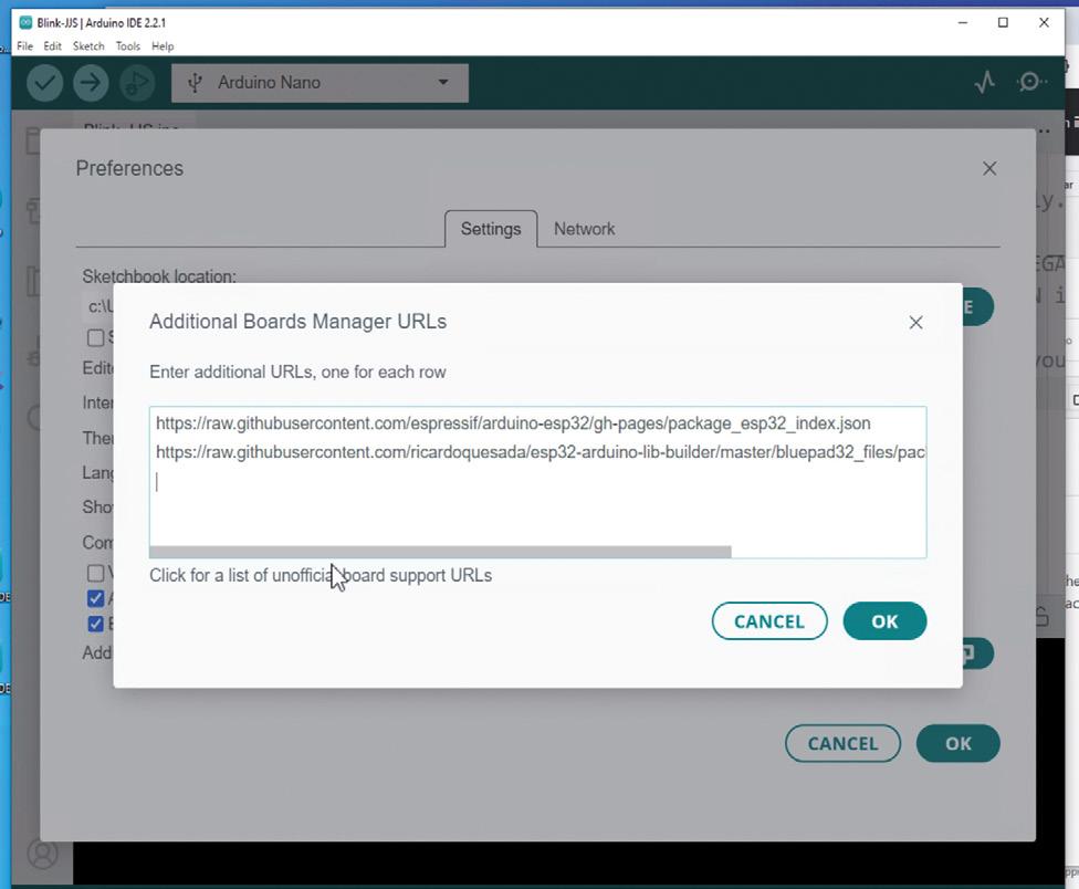
You need to make two URL entries in the IDE Settings/Preferences and then use Board Manager in the IDE to install the needed libraries and examples. The text strings of the URLs are:
https://raw.githubusercontent.com/espressif/arduino-esp32/gh-pages/package_ esp32_index.json
https://raw.githubusercontent.com/ricardoquesada/esp32-arduino-lib-builder/ master/bluepad32_files/package_esp32_bluepad32_index.json
Inserting them in the Mac IDE Preferences looks like the following:

After making the entries here you can use the Board Manager to update the IDE to get access to all ESP32 features and sample code. Here is what the IDE looks like after and before ESP32 boards have been installed:

In the left side of the IDE window click on the Board Manager icon and search for ESP32 in the board search text box. Expect that at least 3 boards will appear. You want to install the three that are shown if they have not already been installed. It may take some time for the install to complete. There is board support from 3 sources: Espressif, Arduino (for its own ESP32 based boards like the Arduino Nano ESP32) and Bluepad32, which is a project headed by Ricardo Quesada that the EEK uses for gamepad connectivity.
In the IDE pick the Preferences item from the File menu and then open the additional boards manager URLs in the dialog and add in the two URLs as shown above and then click OK (twice) before closing the preferences panel.
Expect that by the time the book appears, it's very likely that there will be newer versions for any of the boards installed now. Unless you are right in the middle of a development project, it's a good idea to install the latest versions. This is true for Arduino Libraries as well.
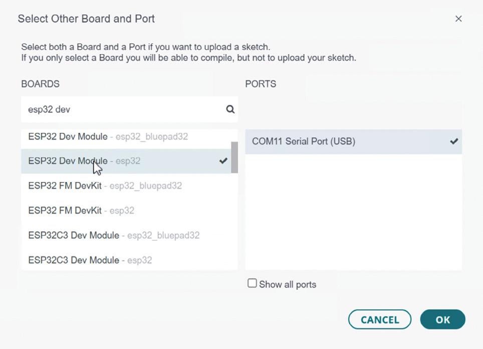
After installing, you can check installation by connecting your ESP32 board to your host through the IDE and running some examples. The board and port you want to connect through will be different for Macs and PCs and the specific ESP32 board that you are using. The screen shot shown below illustrates a possible selection on a PC through a COM port with an ESP32 DevKit. If you try this on your PC, expect that the COM port number you see for selection will be different. If no suitable port appears for selection, you may need to install newer drivers on your PC or check the quality of your USB serial cable connecting your board to the PC.
You don't need to assemble the full EEK for simple testing: just connect the ESP32 board directly to your computer running the IDE using the USB serial cable. This is shown in the image:
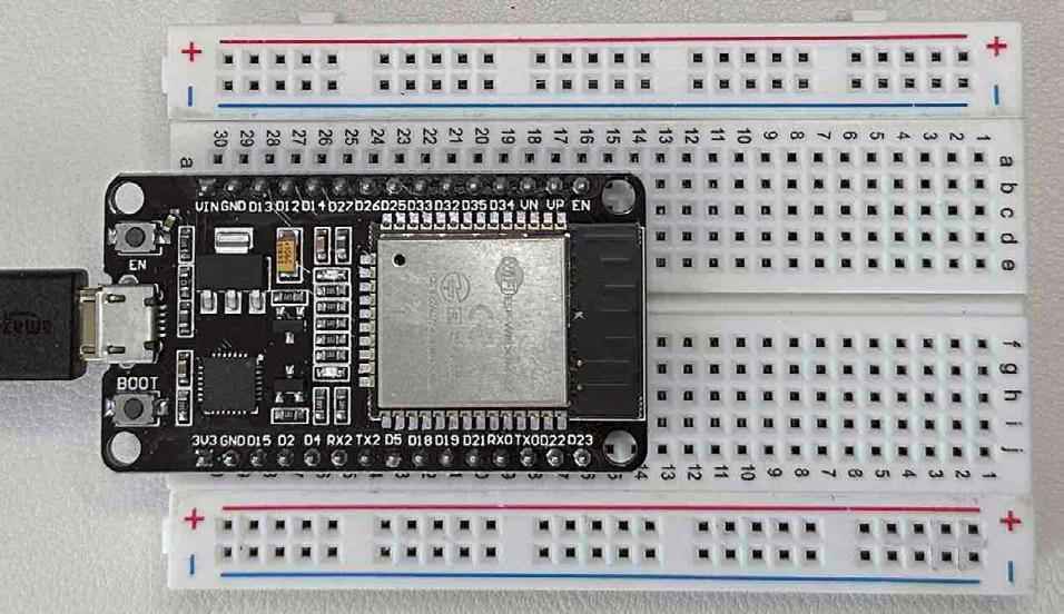
The board shown is the DevKit version on a mini breadboard. You can even use the ESP32 without a breadboard since no GPIO (General Purpose Input Output) pins are being used. You can pick a basic Arduino code example (Arduino code files are called sketches) to get started from the Examples folder in the IDE. It does not have to be ESP32-specific. The complete code for a Basic Blink example can be found in the IDE with the Menu selection File->Examples->Basics->Blink.
2.1 Arduino Basic Blink /* Blink
Turns an LED on for one second, then off for one second, repeatedly.
Most Arduinos have an on-board LED you can control. On the UNO, MEGA and ZERO it is attached to digital pin 13, on MKR1000 on pin 6. LED_BUILTIN is set to the correct LED pin independent of which board is used. If you want to know what pin the on-board LED is connected to on your Arduino model, check the Technical Specs of your board at: https://www.arduino.cc/en/Main/Products
modified 8 May 2014 by Scott Fitzgerald modified 2 Sep 2016 by Arturo Guadalupi modified 8 Sep 2016 by Colby Newman
This example code is in the public domain.
https://www.arduino.cc/en/Tutorial/BuiltInExamples/Blink */
// the setup function runs once when you press reset or power the board void setup() {
// initialize digital pin LED_BUILTIN as an output. pinMode(LED_BUILTIN, OUTPUT); }
// the loop function runs over and over again forever void loop() {
digitalWrite(LED_BUILTIN, HIGH); // turn the LED on (HIGH is the voltage level) delay(1000); // wait for a second
digitalWrite(LED_BUILTIN, LOW); // turn the LED off by making the voltage LOW delay(1000); // wait for a second }
The pin name LED_BUILTIN may not be defined for your ESP32, although it is for the Adafruit Feather ESP32 where it is assigned to GPIO pin number 13. If you get a verification error mentioning an undefined name, you can define a specific numbered GPIO pin as an alternative. For example, for the DevKit ESP32, GPIO pin number 2 identifies one of the onboard LEDs that can be made to blink if you define the LED_BUILTIN name yourself:
#Define LED_BUILTIN 2 void setup() {
// initialize digital pin LED_BUILTIN as an output.
pinMode(LED_BUILTIN, OUTPUT); }
If the modified blink program is compiled and deployed to the DevKit ESP32, you should see an on-board LED blink as shown on the left in this picture:
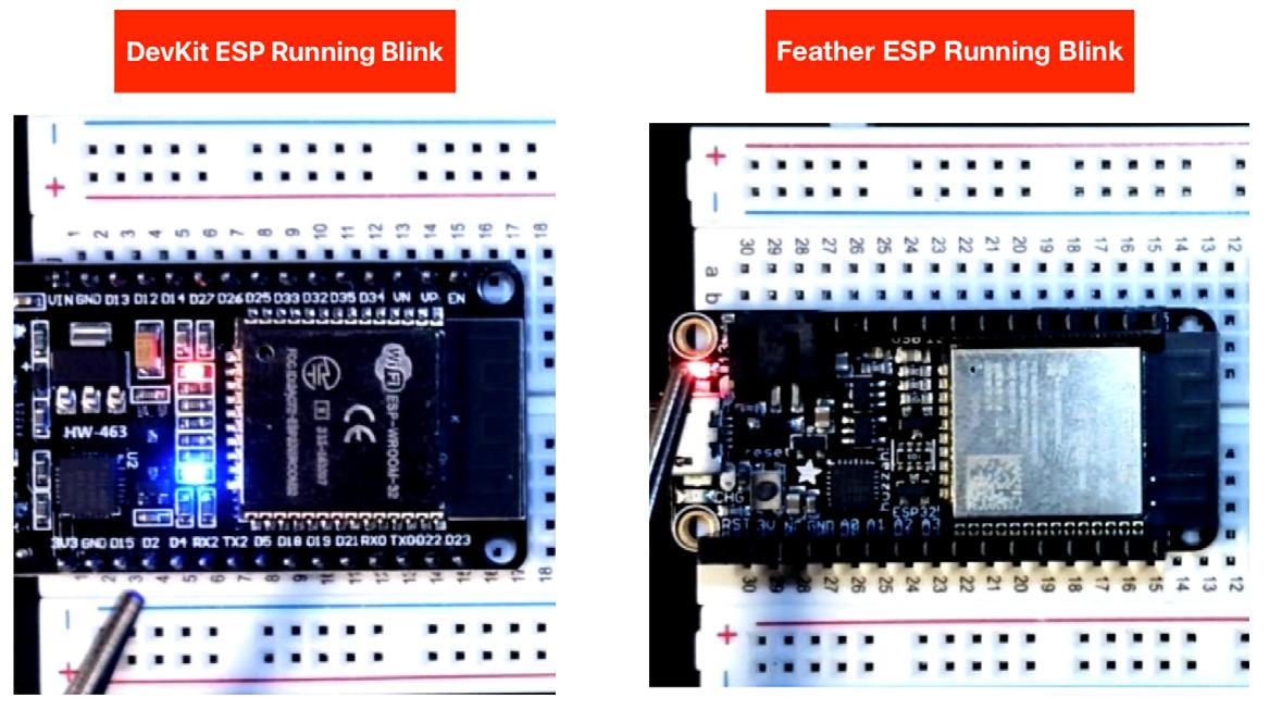
If you can execute a basic example, then you know that the Arduino IDE is installed correctly and ESP32 boards are supported in your installation. The ESP32 on the left is the DevKit. The ESP32 on the right is the AdaFruit Feather also running blink.
Feather Examples PC
The book will cover and often switch between two ESP32 development boards:
• ESP32 DevKit clone
• Adafruit ESP32 Feather Huzzah
The Arduino setup process is the same, but the connection process and some IDE names and features will be different depending on the ESP32 board. There will also be some differences between the Windows PC and Mac Experience. Some simple illustrations of the differences are given in this subsection and the next. Detailed step by step instructions are provided in chapter 5 EEK Basics.
A connected Adafruit ESP32 on the PC will have a different COM port enumeration than the DevKit ESP32 (the COM port number is visible on the lower right of the IDE editor view) but I expect that most of you will have acquired only one ESP32 so the COM port number will not change.
LED_BUILTIN is pre-defined for the Feather. But the location and color of the actual LED on the Feather board is different. The right side of Figure 2.6 image shows the Feather's smaller LED illuminated as the Blink sketch is run.
Another common example to run with ESP32 boards is one that demonstrates WiFi capabilities out-of-the-box. Some boards when then they are connected for the first time will be running a variation of a basic WiFi scanner looking for and reporting on the names of nearby Wireless Access points or SSIDs (Service Set Identifiers). The feather and DevKit boards' set of examples includes such an example as shown below.
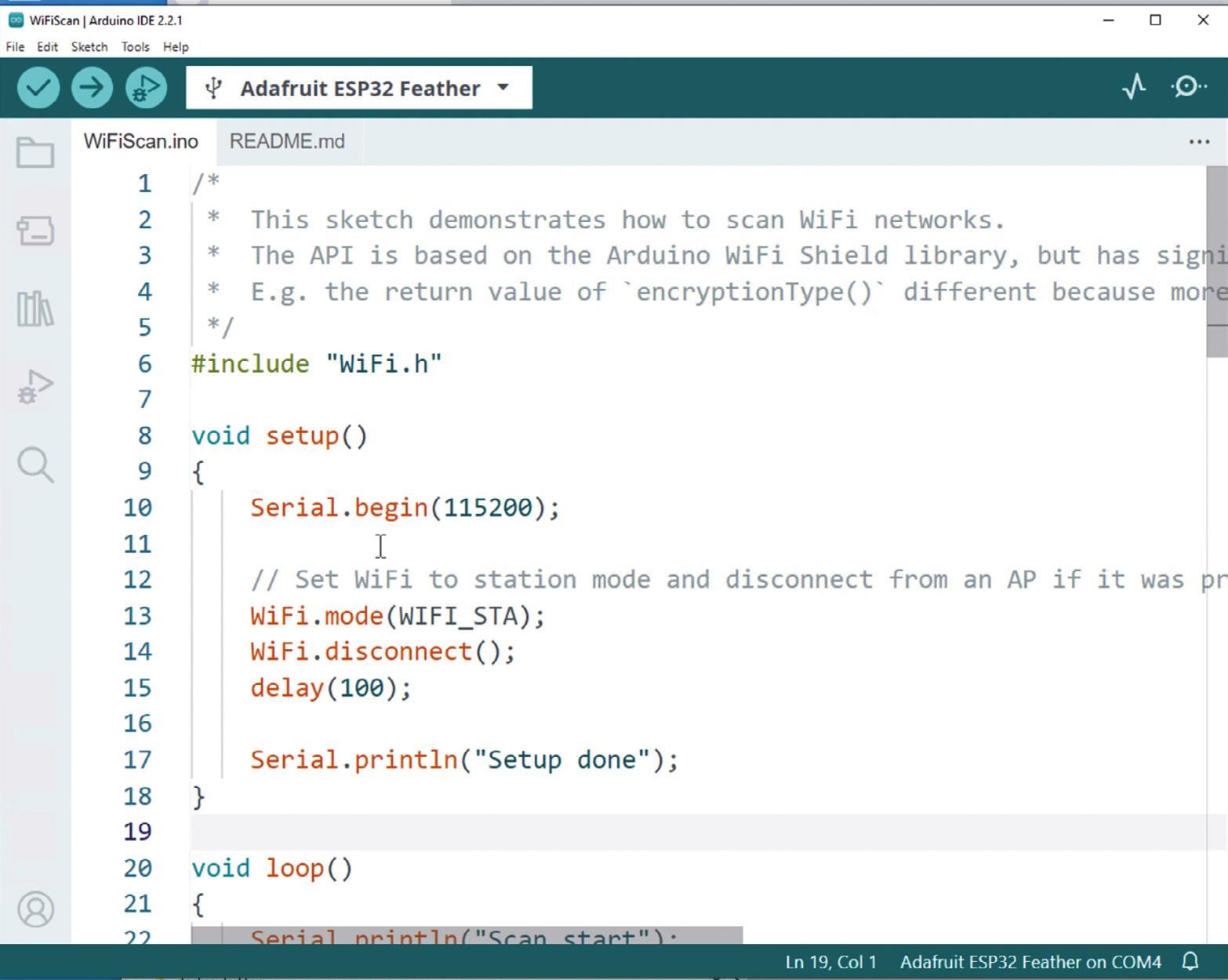
The example can be found via the IDE menu selection File->Examples->Wifi->WiFiScan Once this example is loaded through the IDE, it can be compiled and deployed to the ESP32 Feather. Upon doing so, you can see the repeated reporting through the Serial Monitor window of located SSIDs nearby to the ESP32. The Serial Monitor feature of the IDE is one that you will become very familiar with as you read through and adapt the examples included in the book.

I encourage you to run this example as part of your early testing of the ESP32 board. This section is purposely light on details because of the upcoming chapter content where we will explore the board and a rich set of examples.
I will close this section by briefly turning to the Mac. The full DevKit board experiences shown on the PC can be duplicated on the Mac but for now we will consider just the WiFi Scan example running in the Mac. One significant difference between PC and Mac is how the serial USB port is named/enumerated. In general, there is a more complicated naming convention on the Mac and the USB serial port name for the Feather is even more complicated looking than for the DevKit board. An example for the Feather board is shown below.
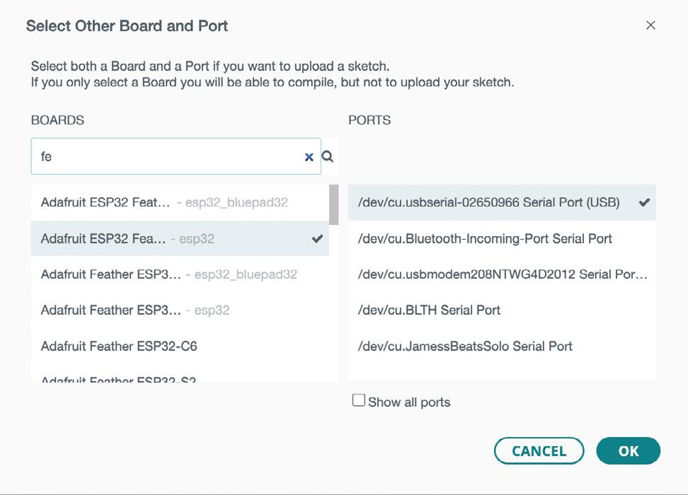
With a DevKit board connected to the Mac, the serial port enumerated string will be like: /dev/cu.usbserial-0001. The key property to look for is the substring usbserial in the name.
When the Blink sketch is compiled and uploaded to the Feather, the small Red LED on the left side of the Feather will be blinking as seen in the right side of Figure 2.6.
Let's try the WiFi scan example on the Mac and we should expect the outcome to be like that on the PC. We find the example in the WiFi examples folder in the IDE. Once it is compiled and uploaded to the Feather on the Mac, we will again see the enumerated list of WiFi named access points (SSIDs).

A Practical Introduction to Embedded Systems with the ESP32
This book is intended for readers who are new to embedded systems and looking for a structured, example-driven way to begin. If you’ve explored general-purpose electronics or Arduino-based resources but found them too broad or lacking in practical application, this guide o ers a more focused alternative.
Using the ESP32 by Example Kit (EEK)—a small, a ordable collection of components including LEDs, sensors, an OLED display, and a motion processor—you’ll build and work with a consistent hardware setup throughout the book. Once assembled, the EEK remains largely unchanged, allowing you to concentrate on learning and experimentation without constant reconfiguration.
Topics include:
> Understanding and programming the ESP32 microcontroller
> Using the Arduino IDE to write and deploy code
> Exploring cyber-physical systems, culminating in basic drone control
No prior experience with Arduino or embedded development is required. Each section includes hands-on examples and mini-projects designed to reinforce core concepts and encourage deeper exploration. By the end, you’ll be equipped not only to reproduce the book’s examples, but also to extend them toward your own ideas and applications.
Whether your interest is in learning embedded programming, building interactive systems, or exploring educational drone control, this book provides a clear and practical path to getting started.

Dr. Jim Solderitsch is an educator, software architect, systems developer, and cybersecurity researcher with a focus on CyberPhysical Systems. He currently serves as an Adjunct Professor in Computing Sciences at Villanova University, where he has also held full-time roles in Mathematics and Electrical and Computer Engineering. He has explored drone control in classroom settings and taught several courses on CyberPhysical Systems using early versions of this book as instructional material. A strong advocate for the Arduino IDE in education, he believes motivated learners with minimal programming experience can start with simple examples and progress to developing advanced applications using wireless, cloud, and drone control technologies.