
Compliances:
POINT OBSTRUCTION LIGHTS POL


INCANDESCENT POINTSPEC® SERIES


ETL Certified FAA L 810 per FAA AC 150/5343H at 55 deg C to +55 deg C

ETL Listed to UL 1598 at 40 deg C to +55 deg C
ETL Listed to CSA C22.2 No. 250.0 04 Canada ICAO Annex 14 Low Intensity Types A (10 cd) & B (32 cd) IMO 2009 MODU Code (2010) paragraphs 13.5.24 & 13.5.25
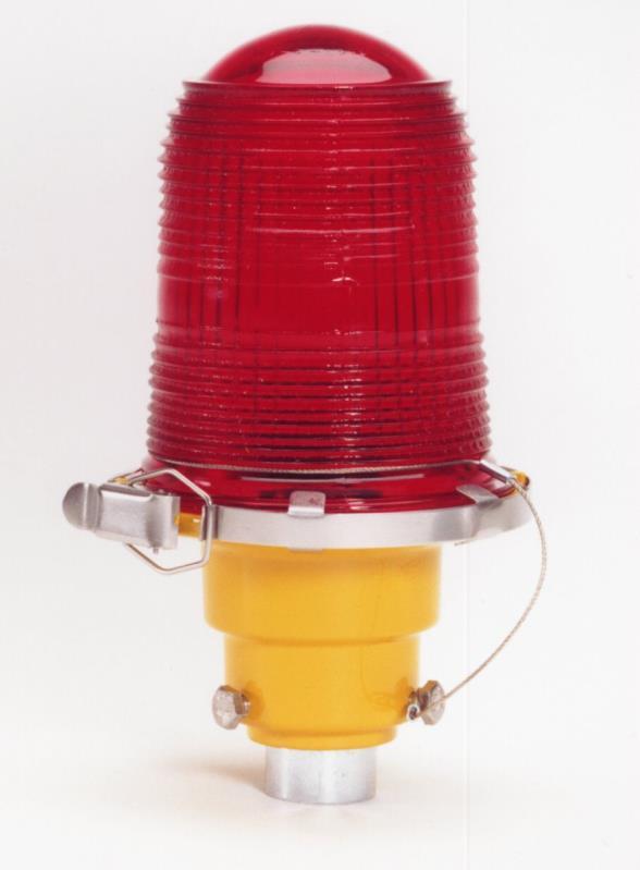
The POL POINTSPEC series of incandescent red aviation obstruction lights presents the highest grade technical features and the most options available in the industry. POL steady burning obstruction lights are used to mark tall structures that present hazards to air navigation. Use the PPC photoelectric controller or option " P" to provide automatic lighting activation at dusk in accordance with FAA specifications. All POINTSPEC POL's include lens & cover tethers, corrosion protection, stainless steel hardware, ground wires & captive cover screws. Lamp life is 8,000 hours for the 120V and 230V screw base lamps.
Point Type Color Lamp & Voltage Entries Style
Options
POL-20000 R: Red 116: 116w 120 volts See See See IR: Infrared 116A2: 116w 230 volts Table 1 Table 2 Table 3 45Q: 45w 6.6A 2-pin 1,2

Notes: 1 Limited options; contact Point Lighting See file OL190LED for the LED series of POL lights
2 Includes 24-inch L-823 lead/plug See file OL150SPC for POL specification guide FAA L-810 certified as: POL-20000 red with 116w FAA lamp number 32
For mounting options and plan details, see file 0MOUNTINGS All details are available as AutoCAD files for insertion in project plans
POL-20000-R-116-34B-DJ
OL 1.1.0 December, 2016
TABLE 1 ENTRY SELECTION
34B 3/4 inch NPT Bottom Entry
34S 3/4 inch NPT Side Entry
34F 3/4 inch NPT Feed thru Entry
10B 1 inch NPT Bottom Entry
10F 1 inch NPT Feed thru Entry
Note: Junction box styles only
M20B Metric Bottom Entry
SF Slipfitter 2.375 inch (60 mm)
TABLE 3 OPTIONS
OPTION: P FAA PHOTOELECTRIC CONTROLLER
POL POINTSPEC® SERIES
POL 20000 R 116 34B
Point Lighting PPC mounted and prewired to the POL to comply with FAA required footcandle specifications. The PPC uses a thermal time delay relay that prevents the accidental turn off of the lights due to stray lighting. The unit is rated for 5000 on off operations minimum and the plug in photocell module is replaceable. Requires a double or single with junction box.
OPTION: FF FLOOR FLANGE
5 inches (127mm) square mounting plate with 4 screw holes and 6 inches (152mm) long pipe extension.
OPTION: BKT TOWER MOUNTING BRACKET
L shaped mounting plain aluminum plate with with mounting hole for light. Installer drills at site for attachment to tower.
OPTION: CF[B] COMPRESSION FITTING
Through holes with 1.5 inch long ¼ 20 hex head stainless steel screws and sealing washers. Metal cable compression fitting for outside diameter: 12 to 18 mm (0.47 to 0.70 inch). Available for 34L unilet style single lights.
OPTION: CF[C] COMPRESSION FITTING
Through holes with 1.5 inch long ¼ 20 hex head stainless steel screws and sealing washers. Metal cable compression fitting for outside diameter: 12 to 18 mm (0.47 to 0.70 inch). Available for all doubles and junction box style single lights.
OPTION: OS OVERRIDE SWITCH
For use with photoelectric controller option P. Cover mounted 3 position switch ON OFF AUTO. Requires a double or single with junction box. For remote override switch, add item PL40110 3.
OPTION: TS TEST SWITCH
Cover mounted toggle switch to simulate failure of primary lamp. Intended to demonstrate proper operation of the standby lamp Requires a double light. Option TSR for use with a remote switch (by others).

OPTION: TP TRANSIENT P
ROTECTION
Metal oxide varistors (MOV’s) are installed to provide limited protection of installed photocell and/or relay against short duration voltage spikes on the line input and load output. The number and configuration will be appropriate to the POL version.
OPTION: MT MARINE TREATMENT
The fixture shall be treated for marine conditions by cleaning per US Department of Defense TT C 490 method III, pretreated with chrome free aluminum conversion coating per US MIL C 5541 type II, epoxy powder base coat primer and glossy polyester powder coat finish in color RAL 6003 (FED STD 595 color #14097) dark green. Powder coating per US Department of Defense MIL PRF 24712A type VI and oven cured.
Note: The POL 20000 is incandescent and, therefore, NVG (night vision) compatible due to the heat signature
POINT OBSTRUCTION LIGHTS
TABLE 2 STYLES
POINTSPEC® SERIES
Style Transfer Alarm Alarm Pilot Flashing Description Non-Isolated Isolated Light
S1
S2
Single: lamp flashing
Single: non isolated alarm
S3 Single: cast aluminum junction box
S4
Single: isolated lamp failure alarm
DJ Double: both lamps operating
DT
D1
D2
D2.2
D3
D4
D4.2
D5
D6
D7
Double: operating lamp & standby with transfer
Double: lamp transfer & pilot light
Double: lamp transfer & alarm
Double: both lamps operating & alarm
Double: lamp transfer, alarm & pilot light
Double: lamp transfer & isolated alarm
Double: both lamps operating & isolated alarm
Same as Style D4 with pilot light
Same as Style D4 with six (6) wires
Double: both lamps flashing
For available options & related specifications, see file OL150SPC Specification Guide Note: The plain single does not have a suffix; a J-box version is required for any single with option P.

POINT OBSTRUCTION LIGHTS POL
POL
POINTSPEC® SERIES SPECIFICATIONS
SPECIFICATIONS OF COMMON VERSIONS OF INCANDESCENT POL OBSTRUCTION LIGHTS
DOUBLE OBSTRUCTION LIGHT
Description: POINTSPEC double POL with both lamps operating and large wiring space. No alarm function.
Specification: The red steady-burning aviation obstruction light shall be FAA L-810 certified. It shall be configured as a 120v (220-240v) double unit with both (2) lamps operating. Alarm sensing, if any, shall be remote from the light unit. There shall be a minimum of 100 cubic inches of enclosed wiring space accessible from the front of the light unit. The lenses of the L-810 light heads and the wiring access cover shall be secured to the unit with tethers. The wiring access cover shall be gasketed to be watertight and have captive screws. Ground wires shall be included. The entire light unit shall be powdercoat painted yellow for corrosion resistance certified by the manufacturer to comply with the US Military Standard Salt Fog Test conducted per MIL-STD810E, Method 509.3, Procedure I. All hardware shall be stainless steel. The red glass lens shall be Fresnel military Type M-1 and shall be certified to meet U.S. military specifications MIL-L-7082D, MIL-C-7989B and the chromaticity requirements of MIL-C-25050. The aviation obstruction light shall be POINTSPEC Series POL-20000-R-116 34B DJ manufactured by Point Lighting Corporation.
DOUBLE OBSTRUCTION LIGHT WITH AUTOMATIC LAMP TRANSFER
Description: POINTSPEC double POL with one lamp operating & one lamp standby. Upon failure of the operating lamp, power is transferred to the standby lamp. No alarm function.
Specification: The red steady-burning aviation obstruction light shall be FAA L-810 certified. It shall be configured as a 120v (220-240v) double unit with one lamp operating and one lamp standby. Upon failure of the operating lamp, power shall be transferred to the standby lamp by means of a current sensing encapsulated electronic module. Alarm sensing, if any, shall be remote from the light unit. There shall be a minimum of 100 cubic inches of enclosed wiring space accessible from the front of the light unit. The lenses of the L-810 light heads and the wiring access cover shall be secured to the unit with tethers. The wiring access cover shall be gasketed to be watertight and have captive screws. Ground wires shall be included. The entire light unit shall be powdercoat painted aviation yellow for corrosion resistance certified by the manufacturer to comply with the US Military Standard Salt Fog Test conducted per MIL-STD-810E, Method 509.3, Procedure I. All hardware shall be stainless steel. The red glass lens shall be Fresnel military Type M-1 and shall be certified to meet U.S. military specifications MIL-L-7082D, MIL-C-7989B and the chromaticity requirements of MIL-C-25050.
The aviation obstruction light shall be POINTSPEC Series POL-20000-R-116 34B DT manufactured by Point Lighting Corporation.
DOUBLE OBSTRUCTION LIGHT WITH AUTOMATIC LAMP TRANSFER & ISOLATED ALARM LINE
Description: POINTSPEC double POL with one lamp operating & one lamp standby. Upon failure of the operating lamp, power is transferred to the standby lamp and to alarm contacts. The contacts are isolated “dry” (voltage free) normally open and normally closed alarm contacts. The installer must provide external power (24v, 120v, 220v, etc.) to the contact(s) which then operate independently of the line power to the POL lamps.
Specification: The red steady-burning aviation obstruction light shall be FAA L-810 certified. It shall be configured as a 120v (220-240v) double unit with one lamp operating and one lamp standby. Upon failure of the operating lamp, power shall be transferred to the standby lamp by means of a current sensing encapsulated electronic module. Upon lamp failure, the electronic relay module shall also activate remote alarm contacts. The contacts shall be isolated “dry” (voltage free). There shall be available both normally open and normally closed alarm contacts. The installer shall provide external power (specify: 24v, 120v, 220v, etc.) to the alarm contact(s) which then operate independently of the line power to the POL lamp. There shall be a minimum of 100 cubic inches of enclosed wiring space accessible from the front of the light unit. The lenses of the L-810 light heads and the wiring access cover shall be secured to the unit with tethers. The wiring access cover shall be gasketed to be watertight and have captive screws. Ground wires shall be included. The entire light unit shall be powdercoat painted aviation yellow for corrosion resistance certified by the manufacturer to comply with the US Military Standard Salt Fog Test conducted per MIL-STD-810E, Method 509.3, Procedure I. All hardware shall be stainless steel. The red glass lens shall be Fresnel military Type M-1 and shall be certified to meet U.S. military specifications MIL-L-7082D, MIL-C-7989B and the chromaticity requirements of MIL-C-25050.
The aviation obstruction light shall be POINTSPEC Series POL-20000-R-116 34B-D4 manufactured by Point Lighting Corporation.
POINT OBSTRUCTION LIGHTS
OINTSPEC® SERIES
REPLACEMENT PARTS
PL10334 Relay, 120/230v PL10001T * Red Lens & Tether
PL10455 1 Relay, Alarm 120v Styles S2, D2 D6 PL10491T ** Infrared Lens & Tether PL10455 2 Relay, Alarm 230v Styles S2, D2 D6 PL10024 116 Lamp 116w, 120v
PL10494 Gasket, Cover for All Doubles PL10025 116 Lamp 116w, 230v
PL10496 Cover & Tether Styles S1 S4 PL10049 O Ring Seal
PL10462 Cover & Tether Double All Styles PL10076 S *** Lamp Socket
PL10606 A 120 Pilot Light 30mm, Amber 120v PL10611 Lamp, Pilot Light 120v
PL10236 120 Photoelectric Subassembly 120v PL10039 Clamp Band
PL10236 230 Photoelectric Subassembly 230v PL10692 Flasher Module 120v PL10237 Photoelectric Socket PL10692 1 Flasher Module 230v
* NSN 6220 01 536 1611
** NSN 6220 01 536 1606 *** NSN 6250 01 536 1597
WEIGHT, DIMENSIONS & SHIPPING DATA
inches (mm) Multi Pack Carton Weight Height Width Depth Qty Weight Dim (inches) Standard Single: 3 lbs 1.4 kg 8.4 (214) 5.0 (127) 5.0 (127) 32 99 lbs 45 kg 22 x 22 x 22 POINTSPEC Single: 7 lbs 3.2 kg 13.9 (353) 6.0 (152) 5.0 (127) 9 66 lbs 30 kg 18 x 18 x 18 POINTSPEC Double: 10 lbs 4.5 kg 13.3 (338) 14.9 (378) 5.0 (127) 3 39 lbs 18 kg 18 x 18 x 19
Wind Loading: Effective Projected Area (EPA) for POINTSPEC Double 0.69 square feet
P O I N T L I G H T I N G C O R P O R A T I O N Mail: P.O. Box 686, Simsbury, CT 06070 Plant: West Dudley Town Rd, Bloomfield, CT Tel 01 860.243.0600 USA Fax 01 860.243.0665 email: Info@PointLighting.com website: www.PointLighting.com
POINT OBSTRUCTION LIGHTS POL P
POINT OBSTRUCTION LIGHTS POL
INCANDESCENT STANDARD SERIES

Compliances: ETL Verified FAA L 810 to FAA AC 150/5345 43H at 55 deg C to +55 deg C ETL Listed to UL 1598 at 40 deg C to +55 deg C ETL Listed to CSA C22.2 No.250.0 04 Canada ICAO Annex 14 Low Intensity Types A (10 cd) & B (32 cd)
POL incandescent red steady burning obstruction lights are used to mark tall structures that present hazards to air navigation. During the night, these lights warn pilots to stay clear of the obstruction when installed in accordance with FAA AC 70/7460 1 and applicable FCC and ICAO rules and recommendations. Each POL includes a lens tether and ground wire. See OL110POL for more options and for double POL’s. Point

POL 20000 R: Red 116: 116 watts, 120 volts 34B: ¾ inch, Bottom BKT: L Bracket, Tower B: Blue 116A2: 116 watts, 230 volts 34L: ¾ inch Unilet MT: Marine Treatment Y: Yellow 45Q: 45 watts, 6.6A * 34S: ¾ inch, Side FF: Floor Flange G: Green 10B: 1 inch, Bottom w/Conduit 6 in C: Clear M20B: Metric, Bottom *Includes 24 inch L 823 lead/plug SF: Slipfitter for 2 3/8 in OD & for 2 inch EMT (60mm) FAA L 810 certified with 116w lamp FAA number 32B
Replacement Red Lens: PL10001T NSN 6220 01 536 1611
Replacement Socket: PL10076 S NSN 6250 01 536 1597
Type Color Lamp & Voltage
Mounting Options
Instruction Sheet: IS20000 Dimensions: Inches (mm) Lamp Life: 8000 Hours Height: 9 0 (229) Width: 5.0 (127) Depth: 5.0 (127) Weight: 4.5 lbs 2.0 kg Volume: 0.5 ft3 0.014 m3 Wind Load: (EPA) 0.17 sq ft For LED units, see file OL190POLv5 OL 1.6.0 December, 2016 POL 20000 R 116 34B
Compliances:
POINT SIGNAL LIGHTS PEL LED
MULTIPURPOSE SIGNAL & WARNING LIGHT
ETL Listed to UL 1598A Marine Vessels at 40 deg C to +55 deg C

ETL Listed to CSA C22.2 No. 137 M1981 & No. 250.0 08 Canada
ETL Listed to UL 1598 at 40 deg C to +55 deg C


ETL Listed Class I, Division 2, Groups A B C D, T5 at 40 deg C to +55 deg C Registered ISO 9001:2015
The PEL AC or DC voltage powered LED multipurpose signal light is an alternative application to the standard FAA obstruction light. The PEL may be used as a visual signal to warn or mark a location, tunnel, walkway, machinery or operating process. The fixture consists of an outer glass lens permanently sealed to a cast aluminum housing. These lights may be installed base up or base down. May be ordered as steady burning or flashing at between 30 fpm and 120 fpm. Includes fused input.
Power consumption is 2.2 watts at 120V.
PointType
PEL-57005

Voltage Array Color Mounting Options
1: 120v C: Signal G: Green 34B: ¾-inch NPT C055: Signal Light* 2: 220v Y: Yellow 10B: 1-inch NPT Fxxx: Flashing (fpm)
3: 12v DC W: White MT: Green Marine Treat. 4: 24v DC R: Red LC: Lens colored 5: 48v DC B: Blue * Required EX: Class I, Division 2 6: 277v
PEL 57005 R 1C 34B C055 F080
With Option EX WITH OPTIONAL GREEN MT
Includes our yellow Marine Treatment finish at no additional charge which tolerates marine, high salt content air and other corrosive environments. The FAA specified finish used by competitors flakes and fails in a short time under such conditions.

Point Lighting Marine Treatment: Ourpaint finish is bonded to the metal and far exceeds the corrosion resistance of the standard FAA approved finish. The fixture shall be treated for marine conditions by cleaningperUSDepartmentofDefenseTT C490methodIII,pretreatedwithchrome free aluminum conversion coating per US MILC5541typeII,epoxypowderbasecoat primer and glossy polyester powder coat finish.PowdercoatingperUSDepartment of Defense MILPRF24712A type VI and ovencured.
SHOWN IN THE BASE DOWN POSITION RED LED SIGNAL LIGHT AT 80 FPM
Color is emitted by the LED array. Standard with clear outer lens Colored glass to match the LED output may be ordered as option LC.
P O I N T L I G H T I N G C O R P O R A T I O N
Mail: P.O. Box 686, Simsbury, CT 06070 Plant: 61 65 W Dudley Town Rd, Bloomfield, CT Tel 01 860.243.0600 USA Fax 01 860.243.0665 email: Info@PointLighting.com website: www.PointLighting.com
OL 1.8.2 April, 2018
POINT OBSTRUCTION LIGHTS POL LED
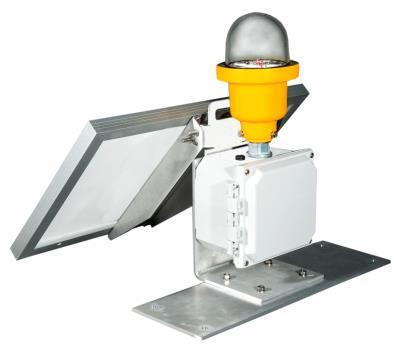


TOWER SERIES & PORTABLE SOLAR LIGHT
Compliances: ETLVerifiedFAAL810toFAAAC150/534543Hat 55degCto+55degC CompliancetoICAOAnnex14LowIntensityTypesA&B RegisteredISO9001:2015

The POL TOWER series of red LED aviation obstruction lights presents high grade technical features in an economical FAA approved obstruction light. POL steady burning obstruction lights are used to mark tall structures that present hazards to air navigation. Use with an FAA photoelectric controller. The POL light heads are permanently sealed and not monitored The peak beam of the POL 22001 is 53 candelas in red. The POL 22001 does not exceed 2.0 watts per head.
Point Type Power * Specification Color Mounting Style Options
POL-22001 1: 96-250V AC F: FAA L-810 & R: Red 34B: ¾-inch, Bottom S: Single SOL: Solar 3: 12 48V DC ICAO Types A/B 10B:1-inch, Bottom D: Double MT: Green Marine M20B: Metric, Bottom S3: Single Treatment SF: Slipfitter w/J-box P: FAA PEC** 2.375-in (60 mm) PM: Post Mount^
* AC voltage range is actual limit suitable for 50 or 60 Hz. DC range is specifically 10.8 to 52.8V. For mounting options and plan details, see file 0MOUNTINGS All details are available as AutoCAD files for project plans FAA approved “lamp” number 630.
** Requires D or S3 ^ Bracket for U-bolts
POL 22001 1F R 34B S SINGLE OBSTRUCTION LIGHT POL 22001 1F R 34B D DOUBLE OBSTRUCTION LIGHT
POL 22001 3F R SOL FP Portable Solar Powered Light with option FP Foot Plate
Important Note: No alarm monitoring possible; no alarm line; no transfer.
Includes our standard yellow Marine Treatment finish which tolerates marine, high salt content air and other corrosive environments. The FAA specified finish used by competitors flakes and fails in a short time under such conditions. Point Lighting Marine Treatment: ThefixtureshallbetreatedformarineconditionsbycleaningperUSDepartmentof DefenseTTC490methodIII,pretreatedwithchromefreealuminumconversioncoatingperUSMILC5541typeII, epoxypowderbasecoatprimerandglossypolyesterpowdercoatfinish.PowdercoatingperUSDepartmentof DefenseMILPRF24712AtypeVIandovencured
OL1.8.9 June, 2018


POL 22001 1F R 34B D MT DOUBLE OBSTRUCTION LIGHT WITH GREEN MARINE TREATMENT FAA L 810 approved Autonomy is 7.3 days (battery capacity without sun) For any location in the world that exceeds 1.2 solar insolation value Includes carry handle May be screwed down to a flat surface or clamped No switching required; operates automatically all night & turns off in the morning POINT OBSTRUCTION LIGHTS POL LED TOWER SERIES & PORTABLE SOLAR LIGHT POL220013FRSOLFP PortableSolarPoweredLight Ships complete as shown P O I N T L I G H T I N G C O R P O R A T I O N Mail: P.O. Box 686, Simsbury, CT 06070 Plant: 61 65 W. Dudley Town Rd, Bloomfield, CT Tel 01 860.243.0600 USA Fax 01 860.243.0665 email: Info@PointLighting.com website: www.PointLighting.com Weight: Single 3.5 lbs 1.6 kg Double 11.8 5.4 Power per head: 120V 1.9 watts 5.0 VA 220V 2.0 5.4 12 24V 0.8 0.8 48V 0.9 0.9
Compliances:
POINT OBSTRUCTION LIGHTS POL LED v5 POINTSPEC® SERIES
ETL Listed to UL 1598A Marine Vessels at 40 deg C to +55 deg C


ETL Listed to CSA C22.2 No. 137 M1981 & No. 250.0 08 Canada
ETL Listed to UL 1598 at -40 deg C to +55 deg C
ETL Verified FAA L-810 to FAA AC 150/5345-43H at -55 deg C to +55 deg C
Registered ISO 9001: 2008

Compliance to ICAO Annex 14 Low Intensity Types A (10 cd) & B (32 cd)
Compliance to CL810 Transport Canada CAR 621, Table 13 2
Compliance to CAP 437 & UK CAP 168 Table 6A.1 Low Intensity (Group A)

IMO 2009 MODU Code (2010) paragraphs 13.5.24 & 13.5.25
American Bureau of Shipping (ABS) Type Approved Product
The POL LED red low intensity obstruction lights are for use on aviation obstructions.
The casting is copper free (< 0.25%) aluminum. The lens is glass.
The hardware is 316 (A4) stainless steel. The LED’s are rated for 100,000 hours.

Only 1.5 watts per head for 120V. IP66 tested and listed.
Standard with the exclusive yellow Point Lighting Marine Treatment finish that is bonded to the metal and far exceeds the corrosion resistance of the standard FAA approved finish.

Six (6) years limited warranty subject to Point Lighting "Terms & Conditions of Sale".
PointType Power* Specification Color Mounting Style Options

POL-21005
1: 120v F: FAA L-810 R: Red 34B: ¾-inch, Bottom S: Single NC: NVG Compatible
2: 220v F: ICAO Type A 10B:1-inch, Bottom D: Double CF: Cable Fitting
3: 12v DC B: Trans. Canada 34F: ¾-in, Feed-thru See Chart on MT: Green Marine
4: 24v DC B: ICAO Type B M20B: Metric, Bottom page 3 Treatment
5: 48v DC B: UK CAP 168 SF: Slipfitter 2.375-in (60 mm) P: Photoelectric
6: 277v Group A Controller
* AC voltages are nominal. See page 4 for operating range; suitable for 50 or 60 Hz.
For mounting options and plan details, see file 0MOUNTINGS
All details are available as AutoCAD files for project plans
FAA approved “lamp” number 631.
POL 21005 1F R 34B S SINGLE OBSTRUCTION LIGHT OL 1.9.0 July, 2018
POL 21005 1F R 34B D DOUBLE OBSTRUCTION LIGHT


POL 21005 1F R 34B D P DOUBLE OBSTRUCTION LIGHT WITH PREWIRED FAA PHOTOELECTRIC CONTROL POL 21005 1F R 34B S2 MT SINGLE OBSTRUCTION LIGHT WITH GREEN MARINE TREATMENT & ALARM RELAY POL 21005 1F R SF S SINGLE OBSTRUCTION LIGHT WITH 60MM SLIPFITTER FITS 2 3/8 INCH TENON POL 21005 1F R 34B EX MT SINGLE OBSTRUCTION LIGHT CLASS I, DIVISION 2 SEE FILE OL194POLEX POL 21005 1F R 34B S3 P SINGLE OBSTRUCTION LIGHT WITH JUNCTION BOX & PREWIRED FAA PHOTOELECTRIC CONTROL
IGHTS POL LED v5 POINTSPEC® SERIES POL 22001 3F R SOL FP PORTABLE SOLAR POWERED LIGHT SEE FILE OL189POL FAA PHOTOELECTRIC CONTROLLER PPC 40700 1 34T SEE FILE OL410PPC
POINT OBSTRUCTION L
S
Standard Single S1
Single flashing (no junction box & no sync) -S15
Single flashing, w/alarm line & J box (Note 1 & no sync) S15K
As above only for use w/POC to flash all lights in sync S1.3
Single with junction box: flashing (Note 1) S2
Single: non isolated alarm (Note 1) -S2.1
DC only; same as Style S2 for use with POC S3
Single: integral junction box & cover (Note 1) S4
Single: isolated failure alarm (Note 1) S5.3
Dual Mode Single: flashing, but may be set in the field to be steady burning (Note 1) D
Double: both heads operating
Double: operating head & standby with transfer
Double: transfer & pilot light
Double: transfer & non isolated alarm (Note 2)
Double: both heads operating & non isolated alarm D3
Double: transfer, non isolated alarm & pilot light
Double: transfer & isolated alarm (Note 2) D4.2
Double: both heads operating & isolated alarm
Same as Style D4 with pilot light (Note 2)
Same as Style D4 prewired with six (6) wires
Double: both heads flashing
Double: primary head flashes and transfer to standby head which flashes; no alarm
Same as Style D8 with alarm line
As above only for use w/POC to flash all lights in sync
Double: transfer, primary head alarm, standby head alarm & power failure alarm; tagged wires
Double: both heads flashing with isolated alarm
Double: both heads flashing; non isolated alarm
As above only for use w/POC to flash all lights in sync
Double: primary head flashes and transfer to standby head flashes; pilot light on transfer
Double: transfer, primary head alarm, standby head alarm; non isolated alarms
Double: primary head flashes and transfer to standby head flashes; with isolated alarm line
Style Transfer Alarm Alarm Pilot Flashing Description Non-Isolated Isolated Light
DT
D1
D2
D2.2
D4
D6
D7
D8
D5
D13
D10
D10K
D14
D15
D15K
D16
D18
D19
STYLE SELECTION CHART POINT OBSTRUCTION LIGHTS POL v5
Note 1: This single has a J box & cover below the LED head assembly; box is required for any single with option P. Note 2: Alarm activates on transfer
ECHNICAL N
OTES
& OPTIONS
POINT OBSTRUCTION LIGHTS POL LED v5
Alarm options must be selected at time of initial order. Alarms cannot be added in the field or retrofitted. POL LED lights cannot be monitored by 3rd party systems or controllers without selecting an alarm version of the POL LED. The POL optical subassembly is factory sealed to prevent moisture penetration and it is not serviceable.
Option MT: Marine Treatment Note: Yellow MT is standard
The fixture shall be treated for marine conditions by cleaning per US Department of Defense TT-C-490 method III, pretreated with chrome-free aluminum conversion coating per US MIL-C-5541 type II, epoxy powder base coat primer and glossy polyester powder coat finish in color RAL 6003 (FED-STD-595 color #14097) dark green. Powder coating per US Department of Defense MIL-PRF-24712A type VI and oven cured.
Option NC: NVG Compatible
Adds infrared LED at 855 nm to allow visibility to pilots with or without night vision goggles.
Infrared Radiant Power F-array: 137 mW/sr B-array: 205 mW/sr
Option P: Photoelectric Control see Detail OL06 in file 0MOUNTINGS
Adds a prewired FAA PEC to single with junction box or double.
Option FF: Floor Flange Mounting see Details OL19 & OL20 in file 0MOUNTINGS
For use with photoelectric controller option P. Cover mounted 3-position switch ON-OFF-AUTO. Requires a double or single with junction box. For remote override switch, add item PL40110-3.
Option CF[C]: Cable Fitting For single with junction box or double
Through holes with 1.5-inch long ¼-20 hex head stainless steel screws and sealing washers. Cable compression fitting for outside diameter: 0.5 to 0.625-inch (12.7 to 15.9-mm).
Option BKT: Bracket for Wall Mounting see Detail OL17 in file 0MOUNTINGS
Simple aluminum bracket for single or double. Screw holes for the structure to be drilled in the field.
Option OS: Override Switch
For use with photoelectric controller option P. Cover mounted 3-position switch ON-OFF-AUTO. Requires a double or single with junction box. For remote override switch, add item PL40110-3.
POWER CONSUMPTION
PER
POLLED LIGHT HEAD
Code Type Voltage Frequency Watts* mA VA*
1F FAA & ICAO A 120 AC 50/60 Hz 1.5 25 2.9
2F FAA & ICAO A 220 AC 50/60 Hz 2.1 25 5.5
3F FAA & ICAO A 12 DC 1.2 96 1.2
4F FAA & ICAO A 24 DC 1.5 62 1.5
5F FAA & ICAO A 48 DC 1.2 25 1.2
6F FAA & ICAO A 277 AC 50/60 Hz 1.9 24 5.9
1B ICAO B & TRAN CAN 120 AC 50/60 Hz 6.9 63 7.6
2B ICAO B & TRAN CAN 220 AC 50/60 Hz 6.9 34 7.4
3B ICAO B & TRAN CAN 12 DC 4.3 470 4.3
4B
ICAO B & TRAN CAN 24 DC 4.3 230 4.3
5B ICAO B & TRAN CAN 48 DC 5.0 104 5.0
6B ICAO B & TRAN CAN 277 AC 50/60 Hz 6.9 28 7.9
Note: For option NC, add 1.0 watts (1.1 VA)
*Power consumption for AC units includes the effect of the unit’s power factor which accounts for the difference between watts and volt amperes. Measurements were made at the nominal AC voltages. The operating range for 120v units: 93 144v; for 220v units: 176 250v; for 277v units: 263 291v
T
POL LED SPECIFICATIONS
SPECIFICATIONS COMMON TO ALL POLLED VERSIONS
The red LED lighted (specify: voltage) aviation obstruction light shall be tested and certified FAA L-810 (ICAO low intensity Type B). The obstruction light shall operate properly at 50 or 60 Hz at an input voltage supply of 120V +/-20% (93V to 144V) or, for 220V units, 176V to 250V or, for 277V units, +/-5% (263V to 291V). Within the preceding ranges, the output to the LED board shall be a controlled, stabilized constant current. The obstruction light shall not exceed 1.5 watts per head for FAA L-810 at 120V.
The AC obstruction lights shall be listed SuitableforUseinWetLocationsto UL1598A Marine Vessels, UL1598 2nd Edition Luminaries; CSA C22.2 No. 250.0-04, 2nd Edition; UL50 11th Edition Standard for Enclosures for Electrical Equipment and CSA C22.2 No. 94-M91 Special Purpose Enclosures. Sealed to IP66 ingress protection.


Special Technical Note*: DC light fixtures shall be reverse polarity protected. * Competitors’ units will fail if installed with reverse polarity.
The unit shall have passed the FAA certification tests: the constant high temperature test to +130 deg F (+55 deg C) and the constant low temperature test to -67 deg F (-55 deg C) conducted in accordance with US MILSTD-810F, Method 501.4, Procedure II; the wind-blown rain test conducted in accordance with US MIL-STD-810F, Method 506.3, Procedure I; and the humidity test shall be in accordance with US MIL-STD-810E, Method 507.3, Procedure I. The complete test regime shall exceed the requirements of NEMA 4X and IP 66. The light head shall be marine treated aviation yellow for high corrosion resistance certified by the manufacturer to comply with the US Military Standard Salt Fog Test conducted per MIL-STD-810F, Method 509.4, Procedure I, paragraph 4.5.2.
The clear lens shall be strong soda lime glass with the wave-length matched to the LEDs to permit the fullest light transmission. The lens shall be smooth and rounded to reduce the adhesion of dirt, ice and snow.
The red emitting LEDs shall meet the chromaticity requirements of US MIL-C-25050. The high output LEDs shall not exceed five (5) in number and shall be the latest technology providing uniform light output over the range required by the governing standard. The LED average life shall exceed 100,000 hours.
The LEDs shall be soldered in a factory set position to insure consistent light output. Wire mounted raised LEDs that can be bent out of position shall be unacceptable and cause for rejection. The LED board shall be treated with a protective dielectric conformal coating for protection from moisture and corrosion.
The power supply board shall include short circuit and open circuit protection and the unit shall be protected from line surges by metal oxide varistors (MOVs). All v5 units shall have the power supply and flasher board (if any) potted in the fixture (head subassembly) casting. There shall be a clear design element for the dissipation of LED heat to insure the LEDs do not fail prematurely.
The double LED light unit shall have an integral cast aluminum junction box with a minimum of 100 cubic inches of enclosed wiring space accessible from the front of the light unit. The wiring access cover shall be gasketed to be watertight, shall have captive screws and shall be secured to the unit with a tether. The cover tether and all hardware shall be stainless steel.
The red LED aviation obstruction light shall be POINTSPEC Series POL-21005 manufactured by Point Lighting Corporation.
Important Note: Alarm options must be selected at time of initial order. Alarms cannot be added in the field or retrofitted. POL LED lights cannot be monitored by 3rd party systems or controllers without selecting an alarm version of the POL LED.
WEIGHT, DIMENSIONS & SHIPPING D
Mail: P.O. Box 686, Simsbury, CT 06070 Plant: 61 65 W. Dudley Town Rd, Bloomfield, CT Tel 01 860.243.0600 USA Fax 01 860.243.0665 email: Info@PointLighting.com website: www.PointLighting.com
P O I N T L I G H T I N G C O R P O R A T I O N
Multi
Carton Weight Height Width Depth Qty Weight
(inches)
PEC Single:
OINT
BSTRUCTION
POINTS
®
ATA inches (mm)
Pack
Dim
POINTS
3.5 lbs 1.6 kg 8.6 (217) 6.0 (152) 5.0 (127) 12 47 lbs 21.3 kg 22 x 15 x 17 POINTSPEC Double: 11.8 lbs 5.4 kg 13.3 (337) 14.9 (378) 5.0 (127) 2 27 lbs 12.3 kg 19 x 19 x 19 Wind Loading: Effective Projected Area (EPA) for POINTSPEC Double 0.69 square feet P
O
LIGHTS POL LED v5
PEC
SERIES
Compliances:
HELIPORT & OBSTRUCTION LIGHTS PEL & POL LED v5 TACTICAL MILITARY

ETL Listed to UL 1598A Marine Vessels at 40 deg C to +55 deg C

ETL Listed to CSA C22.2 No. 137 M1981 & No. 250.0 08 Canada
ETL Listed to UL 1598 at 40 deg C to +55 deg C


ETL Verified FAA L 810 to FAA AC 150/5345 43G at 55 deg C to +55 deg C FAA AC 150/5390 2B Heliport Design Guide
Registered ISO 9001: 2008
Compliance to ICAO Annex 14 Low Intensity Types A (10 cd) & B (32 cd)
The POL and PEL POINTSPEC series of LED aviation obstruction and heliport lights presents the highest grade technical features available in the industry. POL or PEL LED infrared + visible color lights may be separately circuited for military tactical switching between under VFR and “lights out” night vision only operations.

Point Type Power Photometric IR+Color Mounting Style Finish

Obstruction: 1: 120v F: FAA L 810 R: Red 34B: ¾ inch, Bottom D: Double MT: Marine POL 21005 2: 220v G: Green 10B: 1 inch, Bottom Treatment Heliport: 3: 12v DC H: Heliport IR: Infrared SF: Slipfitter 2 in EMT CARC PEL 57005 4: 24v DC 850 nm BP: Baseplate LC: Lens 5: 48v DC Colored 6: 277v
Point Lighting Corporation has developed heliport lighting and obstruction lighting products that are compatible with Night Vision Goggles (NVG) for civilian and military use. Typical Aviator Night Vision Imaging Systems (ANVIS) use technology sensing infrared (IR) light in the 600 to 900 nanometer (nm) wavelength range. Point Lighting IR LEDs emit at 850 nm which is outside the unaided human visual range. Therefore, the light below in IR only mode is intended for tactical use with NVG only and will not be visible to unaided eyes Contact us with the program requirements for your specific application. POL 21005 1F IR+R
Option CARC: Chemical Agent Resistant Coating (CARC) is a finishing procedure to provide protection against chemical and biological weapons and also resist damage and removal by decontaminating solutions. The fixture shall be cleaned per US Department of Defense TT C 490 method III, pretreated with chrome free aluminum conversion coating per MIL DTL 5541 type II, epoxy primed per MIL PRF 53030/53022, finished per MIL DTL 64159 in FED STD 595 color #33446 686A flat tan and oven cured.
OL 1.9.4 May, 2016
Infrared Head Visible Color Visible Red Illuminated
34B D MT
Compliances:
ETL Listed to UL 1598 & to UL 1598A Marine Vessels, IP66 & IP67


ETL Listed to CSA C22.2 No.250.0 04 Canada
ETL Verified FAA L 864 & L 865 to FAA Advisory Circular 150/5345 43H
Compliance to ICAO Annex 14 Medium Intensity Types A, B & C
Compliance to Transport Canada CL864 & CL865
Compliance to UK CAP 168 Medium Intensity & Low Intensity (Group B)
Class I, Division 2, Groups A B C D, T5 at ± 55° C (option EX)

Class I, Zone 2, Groups IIA IIB+H2 IIC, T5 at ± 55° C (option EX)


Registered ISO 9001:2015


American Bureau of Shipping (ABS) Type Approved Product

The PFB LED red and white medium intensity flashing beacons are for use on aviation obstructions.
The casting is copper free (< 0.25%) aluminum. The lens is glass.
The hardware is 316 (A4) stainless steel. The LED’s are rated for 100,000 hours.
IP67 rated moisture & humidity venting. IP66 & IP67 tested and listed.
Standard with the exclusive Point Lighting Marine Treatment finish that is bonded to the metal and far exceeds the corrosion resistance of the standard FAA approved finish. See page 8. Six (6) years limited warranty subject to Point Lighting "Terms & Conditions of Sale".
PointType Color Voltage Options&Accessories
PFB-37002
R: Red 1: AC 96 to 264V, 50/60 Hz SEE TABLES ON PAGE 2 & 3 W:White 3: DC 10.8 to 26.4V (red only) EX: Class I, Division 2 (Zone 2)
G: Green 5: DC 43.2 to 52.8V (red only) Hazardous Location Y: Yellow
ICAO MEDIUM INTENSITY RED WHITE BEACON TYPES B & A FOR USE WITH A POC
THE SEPARATE POWER SUPPLY
OL 2.1.3 June, 2018 PFB 37002 RW 1 BA K
THE BEACON FLASHHEAD IS SHOWN
IS INCLUDED BUT NOT SHOWN
POINT FLASHING BEACON PFB LED FAA L-864 & L-865 ICAO TYPES A, B & C SAFE AREA & HAZARDOUS LOCATION PFB 37002 R 1 F4 FAA L 864 MEDIUM INTENSITY RED BEACON STANDALONE 230V WITH MARINE TREATMENT
POINT FLASHING BEACON
PFB
BEACON SELECTION TABLE
For hazardous atmosphere locations requiring Class I, Division 2 (Zone 2), insert EX after the voltage digit Example: PFB 37002 R 1 EX F4 All beacons include marine treatment as standard. For white & dual hazloc beacons, the power supply (PS) is also Class I, Division 2.
PFB 37002 R x F4 Red FAA L 864 red flashing medium intensity beacon
PFB 37002 W x F5 White FAA L 865 white flashing medium intensity beacon 120v
PFB 37002 W x F5.2 White FAA L 865 white flashing medium intensity beacon 220v
PFB 37002 RW x F4F5 Red White FAA L 864 & L 865 dual red/white flashing beacon 120v
PFB 37002 RW x F4F5.2 Red White FAA L 864 & L 865 dual red/white flashing beacon 220v
PFB 37002 W x A White ICAO Type A white flashing medium intensity beacon
PFB 37002 R x B Red ICAO Type B red flashing medium intensity beacon
PFB 37002 R x C Red ICAO Type C red steady medium intensity beacon
PFB 37002 RW x BA Red White ICAO Types B & A dual red flashing/white flashing
PFB 37002 RW x CA Red White ICAO Types C & A dual red steady/white flashing
PFB 37002 R x T4 Red Transport Canada CL864 red flashing beacon
PFB 37002 W x T5 White Transport Canada CL865 white flashing beacon
PFB 37002 RW x T4T5 Red White TC CL864 & CL865 dual red/white flashing beacon
PFB 37002 R x DL Red UK CAA CAP 168 steady low intensity Group B
PFB 37002 R x DM Red UK CAA CAP 168 steady medium intensity beacon
Note: Every white and dual (red white) beacon includes the flashhead (FH) and the separate wall mounted power supply (PS) Maximum distance of PS to FH is 30m. Red beacons do not use a separate power supply. Systems of two or more white or dual beacons that must flash in sync requires a POC controller and data cable. See OL302POC.
UNIVERSAL OPTIONS
NC NVG Compatibility for night vision
CLxx Cable Loop 3m is included. For longer specify this option. Example: CL06 is a 6m cable loop. Limit is 30m.
Fxxx Flashing at custom rate up to 120 fpm.
BACKUP OPTIONS
SB Standby Beacon: add this option to the 2nd beacon to operate upon failure of the primary beacon. This standby beacon & the primary beacon will be side by side. Includes mounting bracket PL11216 & stainless steel hardware for both beacons.
BBS Battery Backup System: Contact Point Lighting specific configurations Use this option for a single PFB beacon.
LED
FAA L-864 & L-865 ICAO TYPES A, B & C SAFE AREA & HAZARDOUS LOCATION
POINT FLASHING BEACON PFB LED FAA
The basic PFB 37002 beacon catalog number is intended for use with a Point POC Controller for most applications. Other configuration options below are available to be factory installed at time of order. Add the separate FAA Photoelectric Controller to all systems. Add the POC Controller as required by the system. Touchscreen is optional for red lighting POC controllers.
OPTIONS
. SS Power supply enclosure is stainless steel. Only applicable to white or dual beacons.
S12 Shield 120: White beacons only. For use on cylindrical structures such as stacks to eliminate “flash bounce” against the structure. Also reduces power consumption.
S18 Shield 180: White beacons only. For use on flat walls such as buildings to eliminate “flash bounce” against the structure. Also reduces power consumption.
ALARM & CONTROL CONFIGURATION OPTIONS
K Required on every beacon connected to any POC 68xxx series digital controller except 68301.
Lx Standalone white or dual individual beacon used with PPC photoelectric control. x = nominal voltage 1: 120v 2: 220v Note: Not required for a red standalone beacon. Note for FAA approval: L1 range is 108v to 132v; L2 range is 198v to 242v
Note: Touchscreen is standard for every POC controller operating PFB white or dual LED beacons.
The MA options are required for two or three red beacons to be synchronized without a controller. For four (4) or more red beacons, a POC controller is required. Not available for white or dual units.
MA1M
MA1S
Master red beacon to be synchronized with one or more secondary beacons with internal flasher & non isolated alarm line powered by the line voltage; one master beacon per system.
Secondary red beacon synchronized by the above master beacon with internal flasher & non isolated alarm line powered by the line voltage; 1, 2 or 3 secondary beacons per system.
RECOMMENDED OR REQUIRED ACCESSORIES
Required
Required
Each PFB red beacon requires one (1) junction box PL11220 which includes terminal blocks. This is a nominal 8 x 10 x 5 inch NEMA 4X fiberglass box. Includes connections for the data cable shield. PL11220 is also specified for every major cable junction in a vertical riser to ensure proper wiring of all systems including white & dual beacons. Add option SS for stainless steel enclosure.
For every data cable splice, every PL11220 junction box and every white or dual beacon power supply, two (2) data cable shield solder sleeves PL10836 S are required.
Optional Wall mounting or tower pole brackets. See list on page 8 and pages 14 18.
See file OL302POC to select the correct system controller.
Red POL only system: POC 68002 with optional touchscreen on the door.
POC
Red PFB system: POC 68003 with optional touchscreen on the door.
White PFB system: POC 68503 includes touchscreen as standard
Dual PFB system: POC 68503 includes touchscreen as standard
One FAA Photoelectric Controller is required per system. Separately ordered and separately mounted.
PPC
PPC 40700 1 34T For red AC systems with a POC 68002 or POC 68003 Controller
PPC 40700 1 34T OS For red AC beacons without a POC; includes override switch
PPC 40702 1 34T For white or dual AC systems with a POC 68503 Controller
L-865
L-864 &
ICAO TYPES A, B & C SAFE AREA & HAZARDOUS LOCATION
FAA RED BEACON
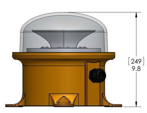
Intensity: 2,000 candelas red night As defined by FAA L 864 Advisory Circular 150/5345 43H
Wattage: 43.4 watts AC peak 7.0 watts AC average F4, T4, B 28.5 watts AC average C 40.4 watts 24V DC peak 5.4 watts 24V DC average
Volt Amps: 72.7 VA AC peak 17.4 VA AC average F4, T4, B 33.5 VA AC average C
Input Range: See voltage ranges page 1
Temp Rating: ± 55° C per FAA certification test
LED Life (hours): 100,000
Cable Loop: Diameter 0.52 inch (13.2mm)
Weight: 17.0 lbs 7.7 kg
Mounting: 4 Holes on 10.5 inch circle
Note: Requires one (1) junction box PL11220 and two (2) data cable solder shields PL10836 S when used with a POC controller (option K).
Note: Cable loop PL11205 6 is not replaceable at the beacon but may be spliced. Conductors are #16 AWG.
Note: A system of one PFB and multiple POL’s may use controller POC 60301 and a data cable is not required.
DATA CABLE
P
OINT
FLASHING BEACON PFB LED
FAA L-864 & L-865
ICAO TYPES A, B & C
SAFE AREA & HAZARDOUS LOCATION
9.8 (249)
Dimensions: Inches (mm)
FAA WHITE BEACON *
Intensity: 20,000 candelas white day 2,000 candelas white night As defined by FAA L 865 Advisory Circular 150/5345 43H
Wattage: 422.0 watts AC peak (day) 84.0 watts AC average (day) 103.0 watts AC peak night) 19.0 watts AC average (night)
Volt Amps: 428.0 VA AC peak (day) 112.0 VA AC average (day) 115.0 VA AC peak (night) 20.0 VA AC average (night)
Input Range: AC only; see voltage range page 1
Temp Rating: ± 55° C per FAA certification test
LED Life (hours): 100,000
Cable Loop: Diameter 0.73 inch (18.5mm)
Weight: 17.0 lbs 7.7 kg
Mounting: 4 Holes on 10.5 inch circle
* Note: Each white beacon assembly consists of a flashhead (FH) and a separate wall mounted power supply (PS). The PFB PS is connected to the FH by cable loop PL10828 14 which exits the beacon and may not be spliced. Conductors are #16 AWG. The maximum cable run length is 30m. See next page for PS enclosure details.
Note: Requires two (2) data cable solder shields PL10836 S when used with a POC controller (option K).
Note: Systems of two or more white or dual beacons that must flash in sync requires a POC controller and data cable.
All PFB beacons connected to a POC system controller require a data cable This cable is one run from the POC controller to the first beacon location and then to each beacon in turn ("daisy chain"). This is normally the most direct method, but the cable is a data bus and may be routed as required with the beacons connected at any point. Each beacon is tagged and labeled with a location address number and the beacons must be connected to the data cable run in that numerical order. This is how the POC identifies each specific beacon and the system will not operate properly unless the beacons are connected in the specified order.
PFBPOWER SUPPLY FIBERGLASS ENCLOSURE For each white & dual beacon
POINT FLASHING BEACON PFB LED
FAA L 864 & L 865
ICAO TYPES A, B & C
SAFE AREA & HAZARDOUS LOCATION
12.4 (315)
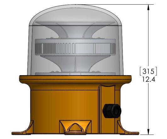
Dimensions: Inches (mm)
FAA DUAL RED/WHITE BEACON *
Intensity: 20,000 candelas white day 2,000 candelas red night As defined by FAA L 864/865 Advisory Circular 150/5345 43H
Wattage: 422.0 watts AC peak (day) 84.0 watts AC average (day) 58.4 watts AC peak (night) 7.0 watts AC average (night)
Volt Amps: 428.0 VA AC peak (day) 112.0 VA AC average (day) 63.5 VA AC peak (night) 24.0 VA AC average (night)
Input Range: AC only; see voltage range page 1
Temp Rating: ± 55° C per FAA certification test
LED Life (hours): 100,000
Weight: 26 lbs 11.8 kg
Mounting: 4 Holes on 10.5 inch circle
* Note: Each dual beacon assembly consists of a flashhead (FH) and a separate wall mounted power supply (PS). The PFB PS is connected to the FH by cable loop PL10828 20 which exits the beacon. Conductors are #16 AWG. The maximum cable run length is 30m.
NEMA4XENCLOSURE: 17.36(441)x15.3(389)x6.67(169)
INCHES(mm) H W D
ENCLOSUREMOUNTINGPATTERN:16.73(425)X12(305)
MOUNTINGHOLEDIAMETER(QTY4):0.32(8)
ENCLOSUREMATERIAL:FIBERGLASS
Note: Requires two (2) data cable solder shields PL10836 S when used with a POC controller (option K).
Note: Systems of two or more white or dual beacons that must flash in sync requires a POC controller and data cable.
See Data Cable note on page 4.
POINTLIGHTINGCORPORATION PFBPOWERSUPPLY
POINT FLASHING BEACON PFB LED

PFBBEACON VENTED TO IP67 & HAZARDOUS LOCATIONS FOR PREVENTION OF MOISTURE INGRESS
Severe environmental conditions with varying temperatures and humidity cause an air pressure differential that results in seal failure of IP66 and IP67 enclosures. Certified fixtures and enclosures begin to leak moist air which the temperature changes turn into condensation. This water can cause failure of the electronic components and corrosion of the metal parts and housing. Point Lighting Corporation uses a very fine pore membrane vent that allows air to pass freely, but water, dust and dirt are prevented from entering. The vent is certified to IP66 & IP67, IEC 600 2 78 humidity, IEC60068 2 11 salt fog, GR 3108 CORE corrosive gases and other IEC standards.
Beacon PFB 37002 with PL10961 M12 HF Vent Installed above the cable entry gland
PFBBEACON FREEZE & HEAT CYCLING TEST PROGRAM TO CONFIRM PREVENTION OF MOISTURE INGRESS CALIBRATED ENVIRONMENTAL CHAMBER
Turn on the chamber, humidity control, dry air purge and ramp to 75°F (24°C) and 70% humidity for baseline readings.
Ramp to 67°F ( 55°C) and 50% humidity at the rate of 2.5°F/min (1h 15m).
Hold at 67°F ( 55°C) for 1 hour.
Ramp to 130°F (+55°C) and 95% humidity at a rate of 2.5°F/min (1h 15m).
Hold at 130°F (+55°C) and 95% humidity for 1 hour.
Repeat steps 2 5 Twenty (20) times
FAA L 864 & L 865 ICAO TYPES A, B & C SAFE AREA & HAZARDOUS LOCATION
STANDARD FINISH:MARINE TREATMENT
Our Marine Treatment tolerates marine, high salt content air and other corrosive environments. The FAA specified finish used by competitors flakes and fails in a short time under such conditions.
Point Lighting Corporation is the only obstruction lighting manufacturer that offers this standard finish. We are the foremost manufacturer of marine offshore helideck lighting operating in severe environments.

The fixture shall be treated for marine conditions by cleaning per US Department ofDefenseTTC490 methodIII,pretreatedwithchromefreealuminumconversioncoatingperUSMILC5541typeII,epoxy powderbasecoatprimerandglossypolyesterpowdercoatfinish.PowdercoatingperUSDepartment of DefenseMILPRF24712AtypeVIandovencured.

OPTIONAL PL40139 HEAT SHIELD

The beacon heat limit is 55 deg C. Installation in higher temperature locations is not warrantied.

The heat shield is framed in stainless steel to be suspended in the air space between the heat source and the beacon. The heat shield is fabricated of a rigid alumina fiber matrix that is stable for continuous use at temperatures up to 3128 deg F (1720 deg C). The material is not affected by oil or water and is resistant to chemicals. The heat shield is 24 inches wide by 36 inches high. The shield should to be oriented as required to maximize protection.
Shown below on a flare shielding an incandescent beacon.
OUCHSCREEN POC 68003& POC 68503
The
These temperatures are surface measurements on opposite faces of the PL40139 Heat Shield. It is expected that the air spaces between the stack skin and the shield and between the shield and the beacon will further limit the heat transmission. See file OL 8.3.0 for details.
PL40139 Heat Shield limits transmission of heat in accordance with these tested temperatures:
STACK FACE BEACON FACE 800 252 F 1200 343 F 1600 F 429 F
S
C
WITH
FAA PHOTOELECTRIC CONTROLLER PPC 40700
INCLUDES OVERRIDE SWITCH POINT FLASHING BEACON PFB LED FAA L 864 & L 865 ICAO TYPES A, B & C SAFE AREA & HAZARDOUS LOCATION Handheld Programmer PL11248 Required for assigning in the field each beacon’s data cable address for replacements and for relocated beacons.
YSTEM
ONTROLLER
T
1 34T OS
POINT FLASHING BEACON PFB LED
FAA L-864 & L-865
ICAO TYPES A, B & C
SAFE AREA & HAZARDOUS LOCATION
SERVICE
The beacon is permanently sealed. Do not attempt to open the beacon. Contact Point Lighting Corporation for return repair service instructions. Do not attempt any testing or procedure not stated in the manual.
SPARE PARTS
The beacon is permanently sealed. We recommend purchasing a spare PFB beacon matching the catalog number of the installed beacons. A spare PFB beacon must be assigned the data address location number of the beacon it is replacing. Therefore, the handheld Field Programmer device must also be purchased (one per site).
PL11248 Handheld programmer for assigning the beacon address in the field
MOUNTING FOOTPRINT
Ø10.5 (Ø267)
Ø0.41 (Ø10.4) use 3/8” screws
12.1 (307)
Cable Loop 3m & gland included
MOUNTING BRACKETS
Beacon:
PL11215
Dimensions: Inches (mm)
Bracket, aluminum with hardware* for bolting to a wall
PL11215 TPM Bracket, aluminum with hardware*; Tower Pole Mount
PL11216 Bracket, as above for wall for two beacons
PL11216 TPM Bracket, as above for two beacons; Tower Pole Mount
PL11217 Bracket, carbon steel with hardware* for one beacon
PL11218 Bracket, carbon steel with hardware* for two beacons
PL10902 Bracket, leveling for wind turbine

Power Supply:
PL11372
Bracket, aluminum with hardware* for bolting to a wall Fits both fiberglass and stainless steel enclosures Fits single and standby type power supplies
PL11372 TPM Bracket, aluminum with hardware*; Tower Pole Mount Fits same as above
Junction Box:
PL11371
Bracket, aluminum with hardware* for bolting to a wall Fits 94 & 98; fiberglass and stainless steel
PL11371 TPM Bracket, aluminum with hardware*; Tower Pole Mount Fits same as above
* 316 stainless steel hardware for attaching the PFB to the bracket
PFB LED
FAA L-864 & L-865 ICAO TYPES A, B & C SAFE AREA & HAZARDOUS LOCATION
DATA CABLE
The data cable is REQUIRED for systems using POC 68003, POC 68503 and POC 68504 controllers. The data cable is NOT required for systems using POC 68002 and POC 60301 controllers.
You may purchase the data cable from Point Lighting under stock number PL10836.
You may purchase the same data cable from others as Belden 9207 Twinax Twinaxial Cable.
You may purchase a data cable from others equal to the above Belden cable with the characteristics listed below. Note: You are responsible to confirm the specifications are equal to the above cable which was used during certification testing. Use of inferior cable may result in improper operation of the system.
The data cable is used as one (1) run from the POC controller to the beacon #1 junction box and then to each beacon junction box in turn ("daisy chain") that terminates at the last numbered beacon The beacons are numbered in sequence and MUST be installed on the data cable in that sequence. This allows the POC system controller to identify and monitor each beacon and synchronize the flashing.
The data cable is a data bus and may be routed as required with the numbered beacons connected at any point. Each beacon is tagged and labeled with a location address number and the beacons must be connected to the data cable run in that numerical order.
PL10836 S shield solder sleeve is required to terminate shield at junction boxes or in line splice the data cable. See Figure 5 below excerpted from our instructions.
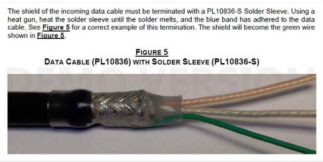
Specifications for your cable supplier: 20 AWG stranded (7x28) one tinned copper conductor, one bare copper conductor, polyethylene (PE) insulation, PE inner jacket, metal foil polyester taped shield 100% coverage, tinned copper braid shield 85% coverage, PVC outer jacket, suitable for outdoor use, UL maximum operating voltage 300V RMS. Conductors: Single pair (2 wires); #20 AWG; 7x28 strand
Insulation: Polyethylene
Outer Shield: Metal foil polyester tape with tinned copper braid Standard: NEC/UL CMG & CL2 with CE mark
Impedance: 100 ohms Inductance: 0.155 μH/ft VP: 66% Delay: 1.54 ns/ft Capacitance conductor to cond.: 14.5 pF/ft Capacitance cond. to shield: 23.0 pF/ft
POINT FLASHING BEACON
AUTOMATIC
FIXED
PFB 37002 R 1 F4 K L 864 LED Beacon
1 System
34T PL11220 94 Junction Box PL11220 94 Junction Box
OINT FLASHING BEACON PFB LED FAA L 864 ICAO TYPES B & C
1F R 34B S2 L 810 LED Single Obstruction Light
TYPICAL RED BEACON SYSTEM
NIGHT OPERATION WITH
BRIGHTNESS
POC 68003 94
Controller PPC 40700 1
P
POL 21005
POC is standard with door mounted touchscreen and PPC override switch
POINT FLASHING BEACON PFB LED FAA L 865 ICAO
TYPE A
TYPICAL WHITE BEACON SYSTEM
AUTOMATIC 24 HOUR OPERATION WITH TWO BRIGHTNESS LEVELS
PFB 37002 W 1 F5 K L 865 Beacon consisting of LED Flashhead & Power Supply
POC 68503 90 1 System Controller
POC is standard with door mounted touchscreen and PPC override switch
Power Supply
Power Supply
PPC 40702 1 34T
TYPICAL DUAL WHITE & RED BEACON SYSTEM AUTOMATIC 24 HOUR OPERATION WITH TWO BRIGHTNESS LEVELS POL 21005 1F R 34B S2 L 810 LED Single Obstruction Light PFB 37002 RW 1 F4F5 K L 864/865 Beacon consisting of LED Flashhead & Power Supply POC 68503 94 1 System Controller PPC 40702 1 34T PL11220 94 Junction Box POINT FLASHING BEACON PFB LED FAA L 864 & L 865 ICAO TYPES A, B & C Power Supply Power Supply
POINT FLASHING BEACON PFB LED FAA L 864 & ICAO TYPES B & C STANDBY RED BEACON ARRANGEMENT PRIMARY BEACON & SIDE LIGHTS WITH AUTOMATIC TRANSFER TO STANDBY POC 68003 94 1 System Controller PPC 40700 1 34T POL 21005 1F R 34B D2 L 810 LED Double Obstruction Light PL11220 94 Junction Box PFB 37002 R 1 B K PFB 37002 R 1 B K SB ICAO Type B Beacons Primary & Standby POC is standard with door mounted touchscreen and PPC override switch PL11220 94 Junction Box
EACON MOUNTING DETAILS
B
B
EACON MOUNTING DETAILS
BEACON MOUNTING DETAILS
BEACON MOUNTING DETAILS
BEACON MOUNTING DETAILS
Compliances:
POINT FLASHING BEACON PFB-AX LED
ATEX-IECEX ZONE 1 & 2 MEDIUM INTENSITY RED BEACONS
IECEx Listed: Ex db eb op is IIB T6 Gb Ta 40 to +55 deg C, IP66 & IP67
ATEX Listed: II 2 G Ex db eb op is IIB T6 Gb Ta 40 to +55 deg C, IP66 & IP67
ETL Verified FAA L 864 to FAA Advisory Circular 150/5345 43H
Compliance to ICAO Annex 14 Medium Intensity Types B & C
Compliance to Transport Canada CL864
Compliance to UK CAP 168 Medium Intensity & Low Intensity (Group B)
Registered ISO 9001:2015
American Bureau of Shipping (ABS) Type Approved Product
The PFB AX red medium intensity LED flashing beacons are specified for use on aviation obstructions.
The castings are copper free (< 0.25%) aluminum. The lens is glass.
The hardware is 316 (A4) stainless steel. The LED’s are rated for 100,000 hours.
Isolated wiring compartment. IP66 & IP67 tested and listed.
Standard with the exclusive Point Lighting Marine Treatment finish that is bonded to the metal and far exceeds the corrosion resistance of the standard FAA approved finish. See page 5.
Six (6) years limited warranty subject to Point Lighting "Terms & Conditions of Sale".
PointType Color Voltage Class Standard&Options
PFB-37002 R: Red 1: AC 96 to 264V AX: ATEX SEE TABLE ON PAGE 2 3: DC 10.8 to 26.4V IECEx 5: DC 43.2 to 52.8V zones 1 & 2
Wattage: 41.7 watts AC Peak at 120V 44.0 watts AC Peak at 220V 7.0 watts AC Average F4 B T4 33.0 watts AC Average C
Volt Amps: 66.0 VA AC Peak at 120V 73.0 VA AC Peak at 220V
Dimensions: Length: 11.1 (282) Width: 12.9 (327) Height: 9.8 (249)

Weight: 25.0 lbs 11.3 kg
Mounting: 4 Holes on a 12.5 (318) circle Inches (mm)
ATEX Certificate Number: CML 17ATEX1250X
IECEx Certificate Number: IECEx CML 17.0141X

PFB 37002 R 1 AX B MT
ICAO MEDIUM INTENSITY TYPE B RED BEACON STANDALONE WITH GREEN MARINE TREATMENT NOTE: STANDARD FINISH IS YELLOW MARINE TREATMENT
OL 2.1.4 June, 2018
POINT FLASHING BEACON PFB-AX LED
ATEX-IECEX ZONE 1 & 2
MEDIUM INTENSITY RED BEACONS
STANDARDS & OPTIONS
F4 FAA L 864 red flashing medium intensity beacon
B ICAO Type B red flashing medium intensity beacon
C ICAO Type C red steady medium intensity beacon
T4 Transport Canada CL864 red flashing beacon
DL UK CAA CAP 168 steady low intensity Group B
DM UK CAA CAP 168 steady medium intensity beacon
NC NVG Compatibility for night vision
MT Green Marine Treatment finish in place of the standard yellow Marine Treatment
Fxxx Custom Flash Rate in flashes per minute
Cxxx Custom versions as assigned by Point Lighting Corporation
CONTROL & ALARMING OPTIONS
Note: Every beacon without one of these control options has line voltage powered alarm conductor.
K Required on every beacon connected to any POC 68xxx series digital controller.
SA2 Voltage Free (dry) Alarm Contact (alarm line is powered by an external source by others)
The MA options are required for two or three PFB AX beacons to be synchronized without a controller. For four (4) or more PFB AX beacons, a POC controller is required.
MA1M
MA1S
Master PFB AX beacon to be synchronized with one or more secondary beacons with internal flasher & non isolated alarm line powered by the line voltage; one master beacon per system.
Secondary PFB AX beacon synchronized by the above master beacon with internal flasher & non isolated alarm line powered by the line voltage; 1 or 2 secondary beacons per system.
ENTRY THREADED HUB OPTIONS
Standard with one ¾ Iinch NPT Hub
10B 1 Inch NPT
M20 Metric M20 x 1.5mm
M25 Metric M25 x 1.5mm
Note: The basic PFB AX beacon catalog number is intended for use with a Point POC Controller for most applications. Other configuration options above are available to be factory installed at time of order. Add the separate FAA Photoelectric Controller to all systems. Add the POC Controller as required by the system. Touchscreen is optional for safe area POC controllers.
POINT FLASHING BEACON PFB-AX LED
ATEX-IECEX ZONE 1 & 2 MEDIUM INTENSITY RED BEACONS
DATA CABLE
All PFB AX beacons connected to a POC system controller require a data cable. This cable is one run from the POC controller to the first beacon location and then to each beacon in turn ("daisy chain"). This is normally the most direct method, but the cable is a data bus and may be routed as required with the beacons connected at any point. Each beacon is tagged and labeled with a location address number and the beacons must be connected to the data cable run in that numerical order. This is how the POC identifies each specific beacon and the system will not operate properly unless the beacons are connected in the specified order.
Options continue on page 3
A data cable is REQUIRED.*
You may purchase the data cable from Point Lighting under stock number PL10836 You may purchase the same data cable from others as Belden 9207 Twinax Twinaxial Cable.
You may purchase a data cable from others equal to the above Belden cable with the characteristics listed below. Note: You are responsible to confirm the specifications are equal to the above cable which was used during certification testing. Use of inferior cable may result in improper operation of the system.
The data cable is used as one (1) run from the POC controller to the beacon #1 junction box and then to each beacon junction box in turn ("daisy chain") that terminates at the last numbered beacon. The beacons are numbered in sequence and MUST be installed on the data cable in that sequence. This allows the POC system controller to identify and monitor each beacon and synchronize the flashing.
The data cable is a data bus and may be routed as required with the numbered beacons connected at any point. Each beacon is tagged and labeled with a location address number and the beacons must be connected to the data cable run in that numerical order.
PL10836 S shield solder sleeve is required to terminate shield at junction boxes or in line splice the data cable. * A data cable is not required for a standalone beacon not connected to a POC system controller.

Specifications for your cable supplier:
20 AWG stranded (7x28) one tinned copper conductor, one bare copper conductor, polyethylene (PE) insulation, PE inner jacket, metal foil polyester taped shield 100% coverage, tinned copper braid shield 85% coverage, PVC outer jacket, suitable for outdoor use, UL maximum operating voltage 300V RMS.
Conductors: Single pair (2 wires); #20 AWG; 7x28 strand
Insulation: Polyethylene
Outer Shield: Metal foil polyester tape with tinned copper braid
Standard: NEC/UL CMG & CL2 with CE mark
Impedance: 100 ohms Inductance: 0.155 μH/ft VP: 66%
Delay: 1.54 ns/ft
Capacitance conductor to cond.: 14.5 pF/ft Capacitance cond. to shield: 23.0 pF/ft
POINT FLASHING BEACON PFB-AX LED ATEX-IECEX ZONE 1 & 2
MOUNTING PATTERN WIRING COMPARTMENT
MEDIUM INTENSITY RED BEACONS
MARINE TREATMENT INCLUDED
Our Marine Treatment tolerates marine, high salt content air and other corrosive environments. The paint finish used by competitors flakes and fails in a short time under such conditions.
OPTIONAL PL40139 HEAT SHIELD
The beacon heat limit is 55 deg C. Installation in higher temperature locations is not warrantied.
ThefixtureshallbetreatedformarineconditionsbycleaningperUSDepartmentofDefenseTTC490 methodIII,pretreatedwithchromefreealuminumconversioncoatingperUSMILC5541typeII,epoxy powderbasecoatprimerandglossypolyesterpowdercoatfinishincoloryellow.PowdercoatingperUS DepartmentofDefenseMILPRF24712AtypeVIandovencured. SYSTEM CONTROLLER WITH TOUCHSCREEN POC 68003 90 1 TS
The heat shield is framed in stainless steel to be suspended in the air space between the heat source and the beacon. The heat shield is fabricated of a rigid alumina fiber matrix that is stable for continuous use at temperatures up to 3128 deg F (1720 deg C). The material is not affected by oil or water and is resistant to chemicals. The heat shield is 24 inches wide by 36 inches high. The shield should to be oriented as required to maximize protection.
Shown below on a flare shielding an incandescent beacon.
These temperatures are surface measurements on opposite faces of the PL40139 Heat Shield. It is expected that the air spaces between the stack skin and the shield and between the shield and the beacon will further limit the heat transmission. See file OL 8.3.0 for details.
The PL40139 Heat Shield limits transmission of heat in accordance with these tested temperatures: STACK FACE BEACON FACE 800 252 F 1200 343 F 1600 F 429 F
Handheld Programmer PL11248
for
POINT FLASHING BEACON PFB-AX LED ATEX-IECEX ZONE 1 & 2 MEDIUM INTENSITY RED BEACONS
Required
assigning in the field each beacon’s data cable address for replacements and for relocated beacons.
PFB-AX
INSTALLATION & SERVICE
During installation, do not open the dome lens. Only open the Junction Box cover and follow instructions.
Do not open the beacon dome lens before contacting Point Lighting Corporation for consultation.
Do not attempt any testing or procedure not stated in the manual. The beacon is fully factory tested and operated for hours before shipment. Any prohibited action will make the warranty void. You may return the unit for factory repair service. PFB 37002 R 1 AX F4 K MEDIUM INTENSITY RED BEACON

SPARE PARTS
We recommend purchasing a spare PFB beacon matching the catalog number of the installed beacons. A spare PFB beacon must be assigned the data address location number of the beacon it is replacing. Therefore, the handheld Field Programmer device must also be purchased (one per site).
PL11248 Handheld programmer for assigning the beacon address in the field Upper dome removal kit: PL11308 Lens Wrench PL10166 274 S O ring 39901 Loctite
Mail: P.O. Box 686, Simsbury, CT 06070
Plant: 61 65 W. Dudley Town Rd, Bloomfield, CT Tel 01 860.243.0600 USA Fax 01 860.243.0665 email: Info@PointLighting.com website: www.PointLighting.com
P O I N T L I G H T I N G C O R P O R A T I O N
POINT FLASHING BEACON
LED ATEX-IECEX ZONE 1 & 2 MEDIUM INTENSITY RED BEACONS
POINT FLASHING BEACON PFB LED HIGH INTENSITY

FAA L 856 & DUAL ICAO TYPES A & B
Compliances: ETL Listed to UL 1598 & IP66
ETL Listed to CSA C22.2 No.250.0 04 Canada
ETL Verified FAA L 856 & L 864 to FAA Advisory Circular 150/5345 43H
Compliance to ICAO Annex 14 High Intensity Types A & B
Compliance to Transport Canada CL 856
Registered ISO 9001:2015

The PFB LED white high intensity flashing beacons are specified for use on very tall aviation obstructions typically only above 500 ft The beacon is unidirectional covering 120 degrees horizontal and operates automatically at three intensities: day, twilight and night. Dual beacons are red in the night mode. Each beacon consists of a flashhead (FH) and a wall mounted power supply (PS).


The body casting is copper free aluminum. The lens is glass.
The hardware is 316 stainless steel. The LED’s are rated for 100,000 hours.
IP67 rated moisture & humidity venting. IP66 tested and listed.
Standard with the exclusive Point Lighting Marine Treatment finish that is bonded to the metal and far exceeds the corrosion resistance of the standard FAA approved finish. See page 2
Three (3) years limited warranty subject to Point Lighting "Terms & Conditions of Sale".
PointType Color Voltage Standard
PFB-38111 W: White 1: AC Power F6: FAA L-856, 270K cds WR: Dual* 96 to 264V HA: ICAO Type A, 200K cds 50/60 Hz HB: ICAO Type B, 100K cds T6: Transport Canada CL 856
* The dual (white red) beacon emits red and infrared in night mode as defined by the character for standard in the catalog number. Day and twilight emit white at the required intensities. Each beacon includes the flashhead (FH), cable loop and the separate wall mounted power supply (PS) It requires three (3) beacons for 360 degrees coverage if installed at a single high point.
Point Lighting can provide layouts for specific buildings and other solid structures to insure full coverage.
Note: A POC 68504 1 system controller switched automatically by photocontrol PPC 40702 1 is always required for operation. The system may incorporate other PFB medium intensity beacons and POL low intensity red obstruction lights.
F4: FAA L 864 (dual only) MB: ICAO Med Type B (dual only) T4: T. Canada CL-864 (dual only)
[1]
PFB 38111 W 1 F6 HIGH INTENSITY WHITE BEACON FAA L 856 FOR USE WITH POC 68504 1 SYSTEM CONTROLLER THE BEACON FLASHHEAD IS SHOWN THE SEPARATE POWER SUPPLY IS INCLUDED BUT NOT SHOWN
OL 2.1.8 July, 2018 THE ONLY FAA APPROVED LED SYSTEM THAT IS MADE IN USA
POINT FLASHING BEACON PFB
LED HIGH INTENSITY FAA L 856 & DUAL ICAO TYPES A & B
BEACON SELECTION TABLE
All beacons include marine treatment as standard. Dual beacon includes infrared LEDs with red portion.
PFB 38111 W 1 F6 White
FAA L 856 white flashing high intensity beacon
PFB 38111 WR 1 F6F4 White Red FAA L 856 & L 864 dual white/red flashing beacon
PFB 38111 W 1 HA White ICAO Type A white flashing high intensity beacon
PFB 38111 WR 1 HAMB White Red ICAO Types high A & medium B dual white/red beacon
PFB 38111 W 1 T6 White Transport Canada CL856 white high intensity beacon
PFB 38111 WR 1 T6T4 White Red TC CL 856 & CL 864 dual white/red flashing beacon
FAA L 856 HIGH INTENSITY WHITE BEACON
Intensity: 270,000 candelas white day 20,000 candelas white twilight (FAA) 2,000 candelas white night
As defined by FAA L 856 Advisory Circular 150/5345 43H
Flash Rate: 40 flashes per minute Coverage: 120 degrees horizontal
Wattage: 41.7 watts AC Peak at 120V 42.0 watts AC Peak at 220V 7.0 watts AC Average 33.0 watts AC Average
Volt Amps: 66.0 VA AC Peak at 120V 78.3 VA AC Peak at 220V
Flashhead Weight: 50.5 lbs 22.9 kg
Mounting: 4 Holes on 10.5 inch
Power Supply Weight: 40.0 lbs 18.1 kg
Temperature: 40 deg C to + 55 deg C
FAA DUAL WHITE/RED INTENSITY BEACON
Intensity: 270,000 candelas white day 20,000 candelas white twilight (FAA) 2,000 candelas red night As defined by FAA L 856 & L 864 Advisory Circular 150/5345 43H
Flash Rate: 40 flashes per minute white 30 flashes per minute red Coverage: 120 degrees horizontal
Wattage: 41.7 watts AC Peak at 120V 42.0 watts AC Peak at 220V 7.0 watts AC Average 33.0 watts AC Average
Volt Amps: 66.0 VA AC Peak at 120V 78.3 VA AC Peak at 220V
Flashhead Weight: 50.5 lbs 22.9 kg Mounting: 4 Holes on 10.5 inch
Power Supply Weight: 40.0 lbs 18.1 kg
Note: Each beacon assembly consists of a flashhead (FH) and a separate wall mounted power supply (PS) in a NEMA 4X stainless steel enclosure. The PFB PS is connected to the FH by cable loops which exit the beacon and may not be spliced. The maximum cable run length is 30m.
Note: One (1) PPC 40702 1 is required for every system. Sold as a separate line item.
[2]
POINT FLASHING BEACON
PFB
LED HIGH INTENSITY
FAA L 856 &
D
UAL ICAO TYPES A & B
PFBBEACON VENTED TO IP67&HAZARDOUS LOCATIONS FOR PREVENTION OF MOISTURE INGRESS
Severe environmental conditions with varying temperatures and humidity cause an air pressure differential that results in seal failure of IP66 and IP67 enclosures. Certified fixtures and enclosures begin to leak moist air which the temperature changes turn into condensation. This water can cause failure of the electronic components and corrosion of the metal parts and housing. Point Lighting Corporation uses a very fine pore membrane vent that allows air to pass freely, but water, dust and dirt are prevented from entering. The vent is certified to IP66 & IP67, IEC 600 2 78 humidity, IEC60068 2 11 salt fog, GR 3108 CORE corrosive gases and other IEC standards.

Beacon PFB 38111 with PL10961 M12 HF Vent Installed above the cable entry gland
PFBBEACON
FREEZE &HEAT CYCLING TEST PROGRAM TO CONFIRM PREVENTION OF MOISTURE INGRESS
CALIBRATED ENVIRONMENTAL CHAMBER
Turn on the chamber, humidity control, dry air purge and ramp to 75°F (24°C) and 70% humidity for baseline readings.
Ramp to 67°F ( 55°C) and 50% humidity at the rate of 2.5°F/min (1h 15m).
Hold at 67°F ( 55°C) for 1 hour.
Ramp to 130°F (+55°C) and 95% humidity at a rate of 2.5°F/min (1h 15m).
Hold at 130°F (+55°C) and 95% humidity for 1 hour.
Repeat steps 2 5 Twenty (20) times
[3]
STANDARD FINISH:MARINE TREATMENT
Our Marine Treatment tolerates marine, high salt content air and other corrosive environments. The FAA specified finish used by competitors flakes and fails in a short time under such conditions.
Point Lighting Corporation is the only obstruction lighting manufacturer that offers this standard finish. We are the foremost manufacturer of marine offshore helideck lighting operating in severe environments.
ThefixtureshallbetreatedformarineconditionsbycleaningperUSDepartmentofDefenseTTC490methodIII, pretreatedwithchromefreealuminumconversioncoatingperUSMILC5541typeII,epoxypowderbasecoat primerandglossypolyesterpowdercoatfinish.PowdercoatingperUSDepartmentofDefenseMILPRF24712A typeVIandovencured.
MOUNTING BRACKETS
Beacon: PL11359 Bracket, aluminum with hardware* for bolting in place
PL11360 Bracket, carbon steel with hardware* for welding in place Note: Installer to paint after installation

Power Supply: PL11372 Bracket, aluminum with hardware* for bolting to a wall Fits both fiberglass and stainless steel enclosures
PL11372 TPM Bracket, aluminum with hardware*; Tower Pole Mount Fits same as above
* 316 stainless steel hardware for attaching the PFB to the bracket
BEACON FLASHHEAD MOUNTING PATTERN
[4]
PFB
FAA
SYSTEM CONTROLLER WITH TOUCHSCREEN POC 68504 26.0 (661) 3.8 (97)
(mm)
POINT FLASHING BEACON
LED HIGH INTENSITY
L 856 & DUAL ICAO TYPES A & B
Inches
POINT FLASHING BEACON
PFB LED H
IGH INTENSITY
FAA L-856 & DUAL ICAO TYPES A & B
DATA CABLE
AdatacableisREQUIRED.
You may purchase the data cable from Point Lighting under stock number PL10836.
You may purchase the same data cable from others as Belden 9207 Twinax Twinaxial Cable.
You may purchase a data cable from others equal to the above Belden cable with the characteristics listed below. Note: You are responsible to confirm the specifications are equal to the above cable which was used during certification testing. Use of inferior cable may result in improper operation of the system.
The data cable is used as one (1) run from the POC controller to the beacon #1 junction box and then to each beacon junction box in turn ("daisy chain") that terminates at the last numbered beacon. The beacons are numbered in sequence and MUST be installed on the data cable in that sequence. This allows the POC system controller to identify and monitor each beacon and synchronize the flashing.
The data cable is a data bus and may be routed as required with the numbered beacons connected at any point. Each beacon is tagged and labeled with a location address number and the beacons must be connected to the data cable run in that numerical order.
PL10836 S shield solder sleeve is required to terminate shield at junction boxes or in line splice the data cable. See Figure 5 below excerpted from our instructions.

Specifications for your cable supplier: 20 AWG stranded (7x28) one tinned copper conductor, one bare copper conductor, polyethylene (PE) insulation, PE inner jacket, metal foil polyester taped shield 100% coverage, tinned copper braid shield 85% coverage, PVC outer jacket, suitable for outdoor use, UL maximum operating voltage 300V RMS.
Conductors: Single pair (2 wires); #20 AWG; 7x28 strand
Insulation: Polyethylene
Outer Shield: Metal foil polyester tape with tinned copper braid Standard: NEC/UL CMG & CL2 with CE mark
Impedance: 100 ohms Inductance: 0.155 μH/ft VP: 66% Delay: 1.54 ns/ft
Capacitance conductor to cond.: 14.5 pF/ft Capacitance cond. to shield: 23.0 pF/ft
[5]
POINT FLASHING BEACON PFB LED HIGH INTENSITY

FAA L 856 & DUAL
ICAO TYPES A & B

BEACON FLASHHEAD DIMENSIONS
Inches (mm)
[6]
BEACON POWER SUPPLY DIMENSIONS STANDARD STAINLESS STEEL ENCLOSURE


POINT FLASHING BEACON PFB LED HIGH INTENSITY
Inches (mm)
BEACON FLASHHEAD
[7]
2
POINT FLASHING BEACON PFB LED HIGH INTENSITY


L
&
T
A
Mail: P.O. Box 686, Simsbury, CT 06070
Plant: 61 65 W. Dudley Town Rd, Bloomfield, CT Tel 01 860.243.0600 USA Fax 01 860.243.0665 email: Info@PointLighting.com website: www.PointLighting.com
[8]
FAA
856
DUAL ICAO
YPES
& B P O I N T L I G H T I N G C O R P O R A T I O N
POINT PHOTOELECTRIC CONTROLLER PPC–EX PPC-AX MEDIUM LOAD EXPLOSION PROOF
Compliance with FAA AC 70/7460 1
Class I, Divisions 1 & 2, Groups B,C,D Suitable for Wet Locations NEMA 4X Class II, Divisions 1 & 2, Groups E,F,G
UL File Number: E139669 Class III CSA File Number: 086146_0_000
The PPC is an FAA specification photoelectric controller designed for individual or a group of POL single and double obstruction lights on one circuit or to switch a POC system controller. The PPC uses a time delay relay that prevents the accidental turn off of the lights due to stray lighting incidence. The unit is rated for 5000 on off operations minimum for more than a decade of reliable performance. The PPC EX has feet for wall mounting. The enclosure has one 1 inch threaded hole at bottom when wall mounted.
Voltage PointType Standard
96 305V AC PPC-40700-1
EX: Class I, Division 2 12 24 48V DC PPC-40003 AX: ATEX zones 1 & 2 96 305V AC PPC 40702-1*

* PPC 40702 1 is for use with Point Lighting white & dual beacon power supplies & controllers that operate day & night.

Load Rating: 8A maximum (AC) 10A maximum (DC) 960 VA at 120V; 1,840 VA at 230V
Switching: Single-pole, single-throw; normally closed Operation: ON by 35 fc (377 lux) evening OFF by 60 fc (646 lux) morning
Temperature: -55°C to +55°C
ACWIRING DIAGRAM
FAA PHOTOELECTRIC CONTROLLER PPC 40700 1 EX
OL 4.2.0 July, 2018
PL40139 Heat Shield designed to protect an obstruction light from excessive heat
When exposure of lighting equipment to the detrimental effects of the high heat is unavoidable, it is recommended that heat shields be deployed. It is not possible to warrant against damage from the unpredictable severe conditions present at the top of a flare stack or other hot process structure. At the request of our customers, we have developed a heat shield product PL40139 to extend the life of the lighting components. The PL40139 Heat Shield may be installed suspended in the air space between the hot metal surface and the lighting fixture. Note! Point Lighting makes no claims regarding the appropriateness of this product for use in a specific application. We present the technical data about the product and the customer bears full responsibility for its selection, mounting position and use. There is no warranty given or implied for this product.


The heat shield is fabricated of a rigid alumina fiber matrix that remains stable for continuous use at temperatures up to 3128 deg F (1720 deg C). The material is not affected by oil or water and it is resistant to chemicals. Do not use in the presence of hydrofluoric acid, phosphoric acid & very strong alkalis. The heat shield is 24 inches wide by 36 inches high and may be mounted in any position. The unit is supplied complete with a carbon steel mounting frame for welding to the structure at both the top and bottom of the heat shield. Option SS for 316L stainless steel mounting frame.

The PL40139 Heat Shield limits transmission of heat in accordance with these tested temperatures:
Stack Side* Light Fixture Side* 800 F 252 F 1200 F 343 F 1600 F 429 F
* These temperatures are surface measurements on opposite faces of the heat shield. It is expected that the air spaces between the stack’s metal surface and the shield and between the shield and the light fixture will further limit the heat transmission. ALUMINA FIBER THERMAL BARRIER BETWEEN 316L STAINLESS STEEL SHEETS
90%
OL 8.3.0 August, 2016
FOR FLARE STACKS
SHIELD IN PLACE AFTER YEARS OF USE ON THE GULF OF MEXICO ALL HARDWARE SS 316L
OF THE COST OF THIS PRODUCT IS IN THE ADVANCED TECHNOLOGY INSULATING MATERIAL See dimensioned drawing on page 2. PL40139 Heat Shield Stainless steel 316L face plates; carbon steel angle weld brackets PL40139 SS Heat Shield Stainless steel 316L face plates; SS 316L steel angle brackets
POINT OBSTRUCTION LIGHTING HEAT SHIELD
1/4-20x1.50" HEX HEAD (TYPICAL SIDES)
1/4-20x1.75" HEX HEAD (TYPICAL TOP AND BOTTOM)
1.00 (25)
0.50 (13)
DETAIL B SCALE: 2x (DIMENSIONS TRUE)
316 STAINLESS STEEL SHEET (TYPICAL 2) THERMAL BARRIER 1" THICK 2 x 2 x 3/16" ANGLED MOUNTING BRACKET (SEE NOTES)
2.00 (50) DETAIL B
0.50 (13)
24.00 (609) 23.50 (597) 16.00 (406) 8.00 (203) Ø0.30 (7)
0.13 TYPICAL
SCALE: 2x (DIMENSIONS TRUE) DETAIL A
DETAIL A
36.00 (914) 35.50 (902) 27.00 (686) 18.00 (457) 9.00 (229)
SCALE: FULL SIZE DETAIL A & BEXPLODED
HEAT BLOCK SHIELD
NOTES: 1.
PL40139 MOUNTING BRACKETS ARE CARBON STEEL. 2.
PL40139-SS MOUNTING BRACKETS ARE 316 STAINLESS STEEL. 3.
ALL HARDWARE IS 316 STAINLESS STEEL.
POINT OBSTRUCTION LIGHTS POL M
ILITARY INFRARED
Tested & Certified FAA L 810* by Intertek Testing Service (ETL) per FAA AC 150/5345 43H Complies with ICAO Annex 14 Low Intensity Types A (10 cd) & B (32 cd)

POL incandescent infrared and visible red steady burning obstruction lights are used to mark tall structures that present hazards to air navigation under VFR and night vision operations. Contact us with the program requirements for your specific application. Examples of versions:

POL 20000 IR+R 116 34B DJ MT Olive drab corrosion resistant finish; no alarms
POL 20000 IR+R 116 34B DJ CARC Military flat tan finish; no alarms
Doubles are wired for the heads to be separately controlled. Ground wires are included.
Point Type Lens Type Lamp & Voltage
Mounting
Version & Options
POL 20000 IR+R ** 116: 116 watts, 120 volts 34B: ¾ inch, Bottom DJ: Double IR (only) 116A2: 116 watts, 230 volts 10B: 1 inch Bottom S3: Single SF: Slipfitter (60mm) MT: Marine Treatment CF[x]: Cable Fitting CARC: Military Tan
** Infrared & Visible Red
* FAA L 810 certified in visible red with 116w lamp FAA number 32B Other requests: Contact factory
POL-20000-IR+R 116 10B-DJ MT
OL 1.2.0 December, 2016
POINT OBSTRUCTION LIGHTS POL MILITARY INFRARED
Marine Treatment MT: Thefixtureshallbetreatedformarineconditionsbycleaningper USDepartmentofDefenseTTC490methodIII,pretreatedwithchromefree aluminum conversioncoatingperUSMILC5541typeII,epoxypowderbasecoatprimerandglossy polyesterpowdercoatfinishincolorRAL6003(FEDSTD595color#14097)darkgreen. PowdercoatingperUSDepartmentofDefenseMILPRF24712AtypeVIandovencured. Note: This was formerly option OD.
Option CARC: ChemicalAgentResistantCoating(CARC)isafinishingproceduretoprovide protectionagainstchemicalandbiologicalweaponsandalsoresistdamageandremovalby decontaminatingsolutions.ThefixtureshallbecleanedperUSDepartmentofDefenseTTC 490methodIII,pretreatedwithchromefreealuminumconversioncoatingperMILDTL 5541typeII,epoxyprimedperMILPRF53030/53022,finishedperMILDTL64159inFED STD595color#33446686Aflattanandovencured.
REPLACEMENT PARTS
PL10001T * Red Lens & Tether PL10491T ** Infrared Lens & Tether PL10024-116 Lamp 116w, 120v PL10025-116 Lamp 116w, 230v PL10494 Gasket, Double Cover PL10076-S Lamp Socket PL10462 Cover & Tether Double PL10049 O-Ring Seal * NSN 6220 01-536-1611 ** NSN 6220 01-536-1606
P O I N T L I G H T I N G C O R P O R A T I O N
Mail: P.O. Box 686, Simsbury, CT 06070 Plant: West Dudley Town Rd, Bloomfield, CT Tel 1 860.243.0600 USA Fax 1 860.243.0665 email: Info@PointLighting.com website: www.PointLighting.com