
Compliances:
POINT HELIPORT LIGHTING HAPI LED

HELICOPTER APPROACH PATH INDICATOR
ETL Listed to UL 1598A Marine Vessels, IP66 & IP67

ETL Listed to CSA C22.2 No. 137 M1981 & No. 250.0 08 Canada

ETL Listed to UL 1598 at 40 deg C to +55 deg C
Class I, Division 2, Groups A B C D, T5 at 40 deg C to +55 deg C
Class I, Zone 2, Groups IIA IIB+H2 IIC, T5 at 40 deg C to +55 deg C
ICAO Annex 14, Volume II, Heliports, 5th ed. (2020)
ICAO Doc 9261, 5th ed. (2021), Part II
American Bureau of Shipping (ABS) Type Approval


FAA AC 150/5390 2C, paragraphs 219, 318 & 418
ONGC (India) FS 4044, paragraph 6.6
Registered ISO 9001:2015

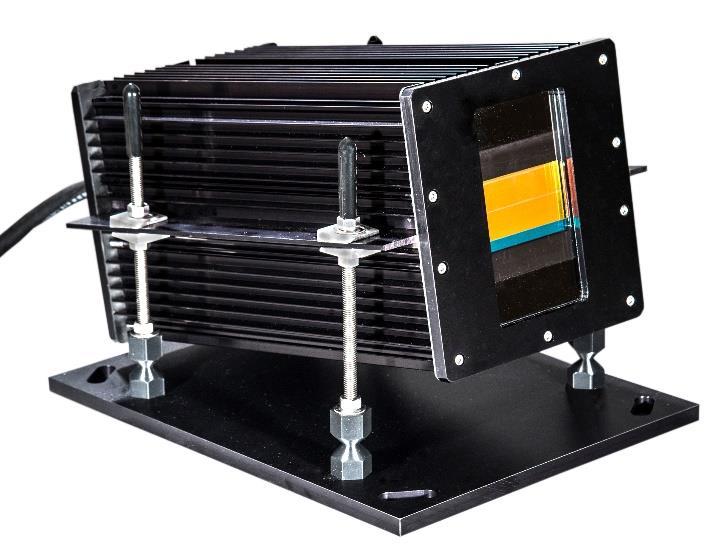
HAPI is a system for use as visual slope guidance on heliports and offshore helidecks. One HAPI system is for one helicopter approach path. It is installed on the side opposite the approach, facing across the landing area. Digital leveling and aiming by means of a handheld field programming device. This may also program the alarm tolerances. For the portable HAPI, see catalog file HL272.
Point Type Voltage Classification Form* Options
HAPI 89001
1: AC, 96 264V (blank): Safe Area F: Frangible See page 2 50/60 Hz EX: Class I, Division 2
3: 24 volts DC Class I, Zone 2
HAPI SIGNALS:
Flashing Above Slope
On Slope
Slightly Below Slope
Flashing Below Slope
Weights: lbs. kg.
Light Unit 25 11.3
Hardware Kit 15 6.8
ROS/ROSW 15 6.8
PLS Assembly 12 5.4
PLS Assembly 14 6.4
* The frangible universal mounting is less than 25 cm tall when installed. Frangible mounting includes four threaded legs with frangible couplings, mounting plate & anchor bolts. The HAPI includes a 3m cable loop as standard.
HAPI 89001 1 F
Dimensions: L: 15.5 (394)
Light Unit W: 12.0 (305)
Inches (mm) H: 9.5 (241)
Power Use: 70 watts 75 VA
Adjustment: 0° to 15°
Brightness: Three (3) steps Control
Alarms: Flasher Failure LED Array Failure Alignment

Important Note:
The HAPI system is a visual slope guidance aid to assist the pilot in aligning the aircraft for approach to landing. It does not replace the pilot’s judgment, skill and responsibility to land the aircraft safely with or without this visual aid.
HL270 March, 2022
POINT HELIPORT LIGHTING HAPI LED
HELICOPTER APPROACH PATH INDICATOR
OPTIONS & ACCESSORIES

EX Hazardous Area Class I, Division 2 (Zone 2) HAPI unit.
JB JBX Junction Box safe area (JB) or Class I, Division 2 (JBX): For mating the cable loop connection at the HAPI with contractor supplied conduit/cabling to the remote mounted PHC, ROS or ROSEX.
PHC See PHC system controller data file HL411PHC. HAPI operation requires either a PHC controller with option HC or one of the ROS options below must be added to the HAPI.

ROS Remote Operator Station: Includes ON OFF switch, brightness control, surge protection, alignment alarm indication and remote alarm contacts in a NEMA 4X (IP66) enclosure.
ROSW Remote Operator Station Wireless: Same as ROS plus wireless ON OFF operation via a key fob operating at 868 MHz when set in the AUTO position. The fob is paired to the HAPI ROS. Note that the ROSW unit is hardwired to the HAPI; only the key fob operation is wireless.
ROSEX Same as ROS except Class I, Division 2 (Zone 2) & NEMA 4X (IP66) enclosure. It is available as ROSWEX wireless operation.
SS Stainless Steel 316L enclosure when used with ROS or ROSW.
GS Gyro Stabilized Mounting (safe area only)
PLB Adds the PLB 40300 wiring junction box recessed in the pavement with baseplate & cable gland for the HAPI’s standard cable loop. For land based installations only and may be used with rigid or frangible HAPI system.
PLS Same as option PLB except uses the PLS 40304 shallow wiring junction box
RECOMMENDED OR REQUIRED ACCESSORIES
Required PL11248 HAPI Programmer


This handheld device is required to install and maintain the HAPI system. It plugs into the HAPI unit to set the leveling and the aiming angle.
Optional
PPC 40700 1 34T Photoelectric Control FAA photoelectric control used with ROS set in AUTO position. View our YouTube flight test video of the HAPI & VAGS Systems at: https://youtu.be/Snmx5vEYuCQ
Please follow Point Lighting Corporation on: FACEBOOK INSTAGRAM YOUTUBE LINKEDIN


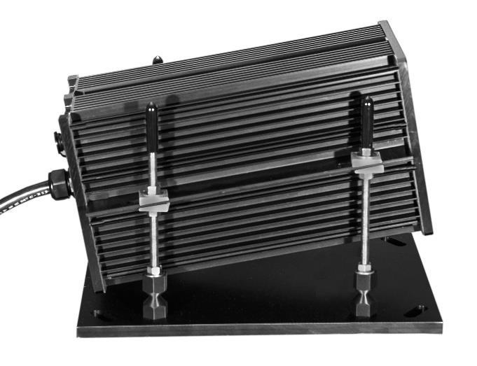
OINT HELIPORT LIGHTING HAPI LED HELICOPTER APPROACH PATH INDICATOR REMOTE OPERATOR STATION ( ROS) OR AS ROSW WITH OPTIONAL WIRELESS CONTROL TYPICAL STANDALONE FRANGIBLE INSTALLATION Power wires must be a minimum of #14 AWG conductor size and the data wires a minimum of #16 AWG for a maximum distance of 250 ft (76m) between the ROS and the HAPI light unit’s cable loop. * The 3 meter cable loop consists of seven (7) conductors all #16 AWG: Line Neutral Ground and four (4) data wires. 11.3 (287) W 13.3 (339) H 5.6 (142) D NEMA 4X Fiberglass IP66 Direction of Aircraft Approach HAPI LIGHT UNIT OPTION PLB BASE & COVER Anchor bolts are included HAPI UNIT SIDE VIEW FRANGIBLE MOUNTING HAPI LEG ASSEMBLY DETAIL SHOWING BEVELED WASHERS FOR POSITIVE MECHANICAL CONTACT CABLE LOOP *
P
POINT HELIPORT LIGHTING HAPI LED HELICOPTER APPROACH PATH INDICATOR


Plugs into the rear of the HAPI unit for leveling and for setting of the aiming vertical angle.
PL11248 HAPI SYSTEM PROGRAMMER
HAPI 89001 1 F FRANGIBLE MOUNTING


POINT HELIPORT LIGHTING HAPI LED HELICOPTER APPROACH PATH INDICATOR ON COURSE FINAL APPROACH HAPI & VAGS INSTALLATIONS AROUND THE WORLD VAGS SYSTEM FOR HORIZONTAL ALIGNMENT ON APPROACH SEE FILE HL275
POINT HELIPORT LIGHTING HAPI LED HELICOPTER APPROACH P
ATH INDICATOR
GYRO STABILIZED MOUNTING OPTION GS

This option is used for a HAPI light unit installed on a mobile marine vessel. The gyro unit stabilizes on the Bank (X) and Elevation (Y) axis so that the mounting arm with HAPI unit will always stay level, regardless of the motions of the vessel.

Note: The HAPI GS unit operates at 24V DC. For 120V and 230V AC power systems, the DC is produced by the ROS control unit.

Weights: lbs. kg. HAPI GS Unit 102.4 46.5 ROS/ROSW 15.0 6.8
Dimensions: Inches (mm) Width: 31.7 (804) Height: 18.6 (473) Depth: 21.9 (555)

Power Use: 156 VA at 120V AC (system) 299 VA at 230V AC

RONT
TOP VIEW F
AIMING:
If the HAPI system is installed with a VAGS system, both systems should be aimed at the same vertical angle. We recommend an On Slope vertical angle setting between 5 and 10 degrees. The HAPI angle must be set so the transition line to flashing red allows the aircraft to clear any obstacles in the approach path.
Not to Scale
P O I N T L I G H T I N G C O R P O R A T
O N
H APPROACH
LEFT BOX
APPROXIMATELY 4 METERS
POINT HELIPORT LIGHTING HAPI LED HELICOPTER APPROACH PATH INDICATOR
I
Mail: P.O. Box 686, Simsbury, CT 06070 Plant: 61 65 W. Dudley Town Rd, Bloomfield, CT Tel 01 860.243.0600 USA Fax 01 860.243.0665 email: Info@PointLighting.com website: www.PointLighting.com
VAGS-89021
FATO HAPI-89001 VAGS-89021 RIGHT BOX
Compliances:
POINT HELIPORT LIGHTING PORTABLE HAPI LED HELICOPTER A

PPROACH PATH INDICATOR
ETL Listed to UL 1598A Marine Vessels, IP66 & IP67

ETL Listed to CSA C22.2 No. 137 M1981 & No. 250.0 08 Canada

ETL Listed to UL 1598 at 40 deg C to +55 deg C
ICAO Annex 14, Volume II, Chapter 5
American Bureau of Shipping (ABS) Type Approval FAA AC 150/5390 2C, paragraphs 219, 318 & 418 ONGC (India) FS 4044, paragraph 6.6


Registered ISO 9001:2015


HAPI is a system for use as visual slope guidance on heliports. One HAPI system is for one helicopter approach path. It is installed on the side opposite the approach, facing across the landing area. Digital leveling and aiming by means of a handheld field programming device. The portable HAPI normally operates on its rechargeable internal battery for up to eight 15 minute landing cycles. Option RF for activation via wireless device is available.

HAPI 89001 3 C082
Important Note:
The HAPI system is a visual slope guidance aid to assist the pilot in aligning the aircraft for approach to landing. It does not replace the pilot’s judgment, skill and responsibility to land the aircraft safely with or without this visual aid.
HL272 January, 2022
HAPI SIGNALS: Flashing Above Slope On Slope Slightly Below Slope Flashing Below Slope
PORTABLE HAPI
READY
FOR DEPLOYMENT DIRECTLY FROM THE CASE
POINT HELIPORT LIGHTING PORTABLE HAPI LED HELICOPTER
APPROACH PATH INDICATOR
OPTION RF: WIRELESS ACTIVATION
Wireless ON OFF operation via a wireless activator device operating at 918 MHz (USA & Australia) or 868 MHz (Europe) Each order will include one wireless activator device.

PORTABLE HAPI FEATURES

✓ Factory preassembled ready to deploy
✓ Rugged carrying case with handles & wheels
✓ Normally operates on internal rechargeable battery
✓ Charging cable also allows for operation on 96 265V AC power
✓ Timer allows for a 15 minute landing cycle & automatically turns off
✓ Eight (8) landing cycles per battery charge
✓ Includes handheld programmer for leveling & approach slope angle
✓ Legs adjust to the desired approach slope angle
✓ Rigid mounting plate for carrying, weighting or staking
Weight HAPI without case: 53 lbs 24.0 kg

Weight empty case: 43 lbs 19.5 kg
Weight Total for Transport: 97 lbs 43.5 kg
HAPI Slope Adjustment: 0° to 15°
Brightness Control: Three (3) steps

HAPI Alarms: Flasher Failure LED Array Failure Alignment

View our YouTube slide show & flight test video of the Portable HAPI Please follow Point Lighting Corporation on: FACEBOOK INSTAGRAM YOUTUBE LINKEDIN
POINT HELIPORT LIGHTING HAPI LED HELICOPTER APPROACH PATH INDICATOR
HAPI 89001 3 C082
Rear View
Plugs into the rear of the HAPI unit for leveling and for setting of the aiming vertical angle.
PL11248 HAPI SYSTEM PROGRAMMER


POINT HELIPORT LIGHTING PORTABLE HAPI LED HELICOPTER APPROACH P
ATH INDICATOR
HAPI LEG ASSEMBLY DETAIL SHOWING BEVELED WASHERS FOR POSITIVE MECHANICAL CONTACT

THE LEGS ADJUST FOR SETTING THE APPROACH ANGLE DESIRED BY THE PILOTS USING THE SYSTEM

POINT HELIPORT LIGHTING PORTABLE HAPI LED HELICOPTER APPROACH PATH INDICATOR
PORTABLE HAPI TRANSPORT CASE WITH WHEELS & HANDLES


AIMING:
If the HAPI system is installed with a VAGS system, both systems should be aimed at the same vertical angle. We recommend an On Slope vertical angle setting between 5 and 10 degrees. The HAPI angle must be set so the transition line to flashing red allows the aircraft to clear any obstacles in the approach path.
OINT
ELIPORT
IGHTING P
ELICOPTER
P O I N T L I G H T I N G C O R P O R A T I O N
H APPROACH
LEFT BOX FATO HAPI-89001
RIGHT BOX APPROXIMATELY 4 METERS
P
H
L
ORTABLE HAPI LED H
APPROACH PATH INDICATOR
Mail: P.O. Box 686, Simsbury, CT 06070 Plant: 61 65 W. Dudley Town Rd, Bloomfield, CT Tel 01 860.243.0600 USA Fax 01 860.243.0665 email: Info@PointLighting.com website: www.PointLighting.com
VAGS-89021
VAGS-89021
FRONT
Not to Scale
POINT HELIPORT LIGHTING

VAGS-SAGA LED
VISUAL ALIGNMENT GUIDANCE SYSTEM SYSTEM ALIGNMENT GUIDANCE APPROACH
Compliances: ETL Listed to UL 1598A Marine Vessels, IP66 & IP67

ETL Listed to CSA C22.2 No. 137-M1981 & No. 250.0-08 Canada

ETL Listed to UL 1598 at -40 deg C to +55 deg C
Class I, Division 2, Groups A B C D, T5 at -40 deg C to +55 deg C
Class I, Zone 2, Groups IIA IIB+H2 IIC, T5 at -40 deg C to +55 deg C
ICAO Annex 14, Volume II, Chapter 5
Registered ISO 9001:2015


VAGS-SAGA is a system for use as visual horizontal alignment on heliports and offshore helidecks. VAGS is the ICAO nomenclature appearing in Annex 14, Volume II, Chapter 5 “…located such that a helicopterisguidedalongtheprescribed track towards the FATO.” This is also popularly referred to as SAGA. One VAGS system is for one helicopter approach path using board mounted LEDs. The two units are installed facing the approach and arranged for left & right signals. Digital leveling and aiming by hand held field programming device. Brightness control is standard.

Point Type — Voltage — Classification — Form* — Options
VAGS-89021 1: AC, 96-264V (blank): Safe Area F: Frangible See page 2 50/60 Hz EX: Class I, Division 2 3: 24 volts DC
* The frangible universal mounting is less than 25 cm tall when installed. Frangible mounting includes four threaded legs with frangible couplings, mounting plate & anchor bolts. The VAGS unit includes a 3m cable loop as standard.
For each of two (2) units:
Dimensions: L: 15.5 (394)
Light Unit W: 12.0 (305)
Inches (mm) H: 9.5 (241)
Power Use: 70 watts 75 VA
Adjustment: 0° to 15°
Brightness: Three (3) steps Control
Alarms: LED Array Failure Alignment
Weights: lbs. kg.
Light Unit 25 11.3
Hardware Kit 15 6.8
PLS Assembly 12 5.4
PLS Assembly 14 6.4
Multiply above by 2 for a system.
ROS/ROSW 15 6.8
Note: One per system.
Red Light: Wide Left
VAGS-89021-1-F
Recommended 4 meters apart
Red Light: Wide Right
White Light: Aligned on Approach

Important Note:
The VAGS system is a visual horizontal guidance aid to assist the pilot in aligning the aircraft for approach to landing. It does not replace the pilot’s judgment, skill and responsibility to land the aircraft safely with or without this visual aid.
HL275 November, 2019
POINT HELIPORT LIGHTING VAGS-SAGA LED
VISUAL ALIGNMENT GUIDANCE SYSTEM SYSTEM ALIGNMENT GUIDANCE APPROACH

OPTIONS & ACCESSORIES
EX Hazardous Area Class I, Division 2 (Zone 2) VAGS unit.
PHC See PHC system controller data file HL411PHC. VAGS operation requires either a PHC controller with option –VC or that one of the –ROS options below must be added to the VAGS.
ROS Remote Operator Station: Includes ON-OFF switch, brightness control, surge protection, alignment alarm indication and remote alarm contacts in a NEMA 4X (IP66) enclosure.
ROSW Remote Operator Station Wireless: Same as –ROS plus wireless ON-OFF operation when set in the AUTO position via a key fob operating at 433.92 MHz. Note that the ROSW unit is hardwired to the VAGS; only the key fob operation is wireless.
ROSEX Same as –ROS except Class I, Division 2 (Zone 2) & NEMA 4X (IP66) enclosure.
SS Stainless Steel 316L enclosure when used with –ROS or –ROSW.
PLB Adds the PLB-40300 wiring junction box recessed in the pavement with baseplate & cable gland for the VAGS’s standard cable loop. For land-based installations only and may be used with rigid or frangible VAGS system.
PLS Same as option –PLB except uses the PLS-40304 shallow wiring junction box.
RECOMMENDED OR REQUIRED ACCESSORIES
Required PL11248-VAGS
This handheld device is required to install and maintain the VAGS system. It plugs into the VAGS unit to set the leveling and the aiming angle.
Optional PPC-40700-1-34T
FAA photoelectric control used with ROS set in AUTO position.
View our YouTube flight test video of the HAPI & VAGS Systems

Please follow Point Lighting Corporation on: FACEBOOK INSTAGRAM YOUTUBE LINKEDIN


TYPICAL STANDALONE FRANGIBLE INSTALLATION


Note: Each VAGS-SAGA system has two light units (left & right) with one ROS control unit or a PHC controller with the required options.
REMOTE OPERATOR STATION (-ROS) OR AS -ROSW WITH OPTIONAL WIRELESS CONTROL
11.3 (287) W 13.3 (339) H 5.6 (142) D
NEMA 4X Fiberglass IP66


Power wires must be a minimum of #14 AWG conductor size and the data wires a minimum of #16 AWG for a maximum distance of 250-ft (76m) between the ROS and the VAGS light unit’s cable loop.
The 3-meter cable loop consists of seven (7) conductors all #16 AWG: Line-Neutral-Ground and four (4) data wires.

POINT HELIPORT LIGHTING VAGS-SAGA LED VISUAL ALIGNMENT GUIDANCE SYSTEM SYSTEM ALIGNMENT GUIDANCE APPROACH
VAGS LIGHT UNIT OPTION -PLB BASE & COVER Anchor bolts are included VAGS UNIT FRANGIBLE MOUNTING VAGS LEG ASSEMBLY DETAIL SHOWING BEVELED WASHERS FOR POSITIVE MECHANICAL CONTACT
Direction of Aircraft Approach
AIMING: If the VAGS system is installed with a HAPI system, both systems should be aimed at the same vertical angle. We recommend an On Slope vertical angle setting between 5 and 10 degrees. The HAPI angle must be set so the transition line to flashing red allows the aircraft to clear any obstacles in the approach path.
POINT HELIPORT LIGHTING VAGS-SAGA LED VISUAL ALIGNMENT GUIDANCE SYSTEM SYSTEM ALIGNMENT GUIDANCE APPROACH P O I N T L I G H T I N G C O R P O R A T I O N
H APPROACH
LEFT BOX FATO HAPI-89001
BOX APPROXIMATELY 4 METERS
Mail: P.O. Box 686, Simsbury, CT 06070 Plant: 61-65 W. Dudley Town Rd, Bloomfield, CT Tel 01 860.243.0600 USA Fax 01 860.243.0665 email: Info@PointLighting.com website: www.PointLighting.com
VAGS-89021
VAGS-89021 RIGHT
Not to Scale
Compliances:
POINT APPROACH LIGHTS HELIPORT SEQUENCE FLASHER SYSTEM LANDING DIRECTION & SIMPLE APPROACH


ETL Listed to UL 1598A Marine Vessels at 40 deg C to +55 deg C
ETL Listed to CSA C22.2 No. 137 M1981 & No. 250.0 08 Canada
ETL Listed to UL 1598 at 40 deg C to +55 deg C FAA Advisory Circular 150/5390 2C Registered ISO 9001:2015


Point Lighting Corporation offers simple preferred approach lights that provide visual alignment cues to the pilot approaching the heliport. This system provides digitally based sequential flashing of the LED, approach, landing direction or lead in lights to point the pilot to the landing pad. The color of the lights may be green or white or as specified. The lights may be PEL elevated or PRL inset lights.
The maximum number of flashing lights is five (5) on an imaginary straight line originating at the center of the TLOF and oriented with the preferred direction of approach. Typically spaced at 15 foot (5 m) intervals beginning at a point not less than 20 feet (6 m) and not more than 60 feet (18 m) from the TLOF perimeter. The sequence flashing lights may be incorporated with a crossbar and other steady burning PRL or PEL lights as a simple approach lighting system (see page 2)
Specify the system as: The Point Lighting sequence flashing landing direction light system.
Specify the lights: For PEL elevated lights, see file HL135PELv5
For PRL semi flush inset lights, see file HL115PRLv4
Select light output color & voltage.
Select option VB Variable Brightness (required) Select mounting base & any other options
Select the control unit: If there will be a PHC Heliport Lighting Controller, add option SEQ or SEQ2.
If there will not be a PHC controller, specify the PL11291 x Control Unit.*
Note: One of the above is required.
* The PL11291 has a wall mounted NEMA 4X fiberglass enclosure that may be installed inside or outside. The control unit’s input AC voltage must match the lights. 1 = 120v 2 = 220 240v
Flashing in sequence toward the landing pad
Direction of the approach to the heliport
HL137
December, 2019
POINT APPROACH LIGHTS
HELIPORT SEQUENCE FLASHER SYSTEM LANDING DIRECTION & SIMPLE APPROACH
The sequence flashing system may be configured as a night time simple approach lighting system with a layout typical of ICAO Annex 14, Volume II “Heliports”, Figure 5 10.

The lights are normally all white with four (4) sequence flashers in a line as shown below and seven (7) steady burning lights. This economical system is intended for use at night to indicate the preferred approach path to the landing pad.
The PL11291 control unit* is a wall mounted NEMA 4X fiberglass enclosure which may be installed inside or outside. The control unit includes contacts for both the sequence flashing and steady burning lights. It also includes the required circuit level surge protection so it is best to install it close to the lighting.
* If this lighting will be powered by a PHC heliport lighting system controller, delete the PL11291 and add PHC option SEQ to the catalog number.
PLB or PLS light bases should be installed in concrete footings if this system will be installed in earth away from the paved landing area.
Semi flush inset system:
Elevated system:
Qty 4 PRL 97004 2H W PLB VB 7 PRL 97004 2H W PLB 1 PL11291 2
Qty 4 PEL 57005 2H W PLB VB 7 PEL 57005 2H W PLB 1 PL11291 2
Mail: P.O. Box 686, Simsbury, CT 06070 Plant: 61 65 W. Dudley Town Rd, Bloomfield, CT Tel 01 860.243.0600 USA Fax 01 860.243.0665 email: Info@PointLighting.com website: www.PointLighting.com
O I N T L I G H T I N G C O R P O R A T I O N
Typical ICAO Layout for a Simple Approach Lighting System P
Compliances:
POINT HELIPORT BEACON PHB LED IDENTIFICATION BEACON

ETL Listed to UL 1598 & UL 1598A Marine Vessels, IP66 & IP67

ETL Listed to CSA C22.2 No.250.0 04 Canada
ETL Verified FAA L 864 to FAA Advisory Circular 150/5345 43H
Registered ISO 9001:2015 FAA Advisory Circular 150/5390 2B, para. 210.f, 310.h, 410.f. ICAO Annex 14 Heliports, Volume II, para. 5.3.2. 1 to 5 ICAO Annex 14 Aerodromes, Volume I, para. 5.3.3.8 to 14

Army TM 5 811 5, para. 7 5.b. Station Identification Transport Canada CAR 325.33 (option M)
Class I, Zone 2, Groups IIA IIB+H2 IIC, T5 at ± 55° C (option EX) American Bureau of Shipping (ABS) Type Approved Product

The PHB LED medium intensity identification beacon is specified to mark the heliport or airport location All castings are aluminum, all hardware is stainless steel and the lens is glass. There is no plastic. All exterior metal beacon parts are powdercoat painted aviation yellow for corrosion resistance that meets the US Military Standard Salt Fog Test conducted per MIL STD 810F, Method 509.4, Procedure I
Point Type Color Voltage Options (see pages 2 & 3)
PHB 37002 W: White 1: AC H: Heliport 3 Color Flash Control G: Green 3: DC 12 & 24V HA: Heli/Airport 2 Color Flash Control Y: Yellow M: Morse Code (ICAO) Flash Control R: Red MA: Morse Code with Alarms * C066: Brightness Control ** MT: Marine Treatment EX: Class I, Div 2, Groups A B C D, T5 NC: NVG Compatibility
PHB 37002 WGY 1 H
DP: Double Peak White (with H or HA) SOL: Solar Powered DC (with M only)
* FIELD PROGRAMMABLE A beacon with option MA may be reprogrammed with a new message using our optional handheld device. ** BRIGHTNESS CONTROL 3 step brightness control by selecting option C066. Has a separate control unit and requires option MA.
FEATURES
• Over voltage & over current protection

• Short circuit & open circuit protection
•
•
HL315 September, 2022
Metal oxide varistor surge protection
No external plastic parts
51.1 watts
30.0 watts
38.0
65.6
36.0
74
• Factory sealed Intensity: 2,000 candelas option H 2,500 candelas option M Wattage:
Peak (AC) option H & HA
Average (AC) option H
watts Average (AC) option HA
watts Peak (AC) option M
watts Average (AC) option M & MA Volt Amps: 104 VA (AC) option M
VA (AC) option H/HA Input Range: 96 to 264 volts AC; 50 or 60 Hz 10.8 to 26.4 volts DC LED avg. life: 100,000 hours Temp Rating: ± 55° C Dimensions: Inches (mm) 12.1 (306) x 12.1 (306) x 9.8 (249) H Weight:: 20.2 lbs 9.2 kg Mounting: 4 Holes on 10 5 inch circle
ICAO
HELIPORT BEACON PHB LED
IDENTIFICATION BEACON MORSE CODE BEACON
Compliances: ETL Listed to UL 1598 & UL 1598A Marine Vessels & IP66
ETL Listed to CSA C22.2 No.250.0 04 Canada Registered ISO 9001:2015
ICAO Annex 14 Heliports, Volume II, para. 5.3.2. 1 to 5 Transport Canada CAR 325.33 (option M)
Class I, Division 2, Groups A B C D, T5 at ± 55° C (option EX)
Class I, Zone 2, Groups IIA IIB+H2 IIC, T5 at ± 55° C (option EX)
IECEx Listed: Ex db eb op is IIB T6 Gb Ta 40 to +55 deg C, IP66 & IP67
ATEX Listed: Ex II 2 G Ex db eb op is IIB T6 Gb Ta 40 to +55 deg C, IP66 & IP67
The PHB LED ICAO identification beacon is specified to mark the heliport or airport location by emitting a flashing Morse code signal. The standard signal is a Morse code “H”, but the factory can program any signal such as site identifier or radio frequency number. Available in white or green light output.
BRIGHTNESS CONTROL: The PHB with option M for Morse code is available with 3 step brightness control (30 60 100%) by adding option C066.
OPTION EX: Class I, Division 2 (Zone 2) listed.
OPTION AX: ATEX & IECEx Zones 1& 2 listed. Requires option MA.
OPTION M: ICAO Identification Beacon
The Morse code beacon shall comply with ICAO Annex 14, Volume II, paragraph 5.3.2 and Transport Canada CAR 325.33 The basic unit shall flash message “H” unless the user specifies a different message to be factory programmed. The peak beam in white shall be 2,500 candelas. For the ICAO aerodrome identification beacon, the light output color is green and specify the code message.
OPTION C066: Brightness Control
With required option MA, this option adds a separate control unit in a NEMA 4X (IP66) wall mounted enclosure to produce three (3) brightness steps at 100% 60% 30% of normal. An ON OFF AUTO switch on the door may be used with an FAA photoelectric controller (PPC ordered separately) when set in the AUTO position.
Note: Not available for two and three color PHB beacons.
OPTION NC: Night Vision Goggle (NVG) Compatibility
The beacon shall be “visible” to pilots wearing NVG by adding infrared LEDs. Single wavelength colored LEDs are not within the wavelength range of most NVG.
OPTION MA: ICAO Identification Beacon with Alarm Monitoring
In addition to the features of option M, the Morse code beacon shall have a line powered alarm line for LED array failure alarm and flasher failure alarm The beacon message may be reprogrammed using our optional handheld device PL11248 MA.
OPTION SOL: Solar Powered ICAO Identification Beacon
Order as PHB 37002 W 3 M SOL for automatic operation with solar power package included.
Handheld Programmer PL11248 MA

Required for changing the Morse code message in the field.
PHB 37002 W 1 MA C066 MT NC
ICAO MORSE CODE IDENTIFICATION BEACON with Brightness Control (control Marine Treatment & NVG Compatibility

POINT
POINT HELIPORT BEACON PHB LED IDENTIFICATION BEACON
SPECIFICATION
The PHB POINTSPECTM series LED heliport identification beacon shall be listed Suitablefor Use in Wet Locationsto UL1598A Marine Vessels, UL1598 2nd Edition Luminaries; CSA C22.2 No. 250.0 04, 2nd Edition. Sealed to IP66 and IP67 ingress protection.
All hardware shall be 316L stainless steel. All exterior copper free aluminum cast beacon parts shall be powdercoat painted aviation yellow for corrosion resistance that meets the US Military Standard Salt Fog Test conducted per MIL STD 810E, Method 509.4, Procedure I. The clear lens shall be made of strong soda lime glass. There shall be no plastics used in the structural construction of the beacon.
OPTION M:
The Morse code beacon shall comply with ICAO Annex 14, Volume II, paragraph 5.3.2 and Transport Canada CAR 325.33. The basic unit shall flash message “H” unless the user specifies a different message to be factory programmed. The peak beam in white shall be 2,500 candelas. For the ICAO aerodrome identification beacon, the light output color is green and specify the code message
OPTION MA:
In addition to the features of option M, the Morse code beacon shall have a line powered alarm line for LED array failure alarm and flasher failure alarm. The beacon message may be reprogrammed using our optional handheld device PL11248 MA.
OPTION H:
The 3 color heliport beacon shall flash alternately white (clear), yellow, green at the FAA specified flash rate of 36 flashes per minute. The beacon is low intensity at 2,500 candelas in white intended for use at privately owned heliports where an optional visual aid is desired to enhance marking the heliport site location as noted in FAA Advisory Circular 150/5390 2B, paragraph 210.f (2004).

Flash rate: 36 per minute Each color flashes 12 times per minute
OPTION HA:
The 2 color heliport beacon shall flash alternately white (clear) and green or yellow at the FAA specified flash rate of 24 flashes per minute. The beacon is low intensity at 2,500 candelas in white intended for use at privately owned airports and heliports where an optional visual aid is desired to enhance marking the site location.
Flash rate: 24 per minute Each color flashes 12 times per minute
OPTION DP:
The flash of the white (clear) LEDs shall be double peaked (meaning a double flash) as appears in US Military specifications. Requires H or HA.
OPTION MT:
The beacon shall be treated for marine conditions by cleaning per US Department of Defense TT C 490 method III, pretreated with chrome free aluminum conversion coating per US MIL C 5541 type II, epoxy powder base coat primer and glossy polyester powder coat finish in color RAL 6003 (FED STD 595 color #14097) dark green. Powder coating per US Department of Defense MIL PRF 24712A type VI and oven cured.
POINT HELIPORT BEACON PHB LED IDENTIFICATION BEACON
SERVICE
MOUNTING FOOTPRINT
BEACON CABLE LOOP
Ø10.5 (Ø267)
Ø0.41 (Ø10.4) use 3/8” screws


The beacon is permanently sealed. Do not attempt to open the beacon. Do not attempt any testing or procedure not stated in the manual. 12.1 (307 )
Length: Three (3) meters Type: SOW 600 volt Wires: Three (3) each #14 AWG
Dimensions: Inches (mm)
Cable Loop 3m & gland included
Adjustable for a 3 in to 6 in (76 to 152) diameter pole

Includes Stainless
Beacon
P O I N T L I G H T I N G C O R P O R A T I O N
Bracket PL11215 For Wall Mounting Bracket PL11215 TPM Tower Pole Mounting Anodized Aluminum
Steel
Mounting Hardware
Mail: P.O. Box 686, Simsbury, CT 06070 Plant: 61 65 W. Dudley Town Rd, Bloomfield, CT Tel 01 860.243.0600 USA Fax 01 860.243.0665 email: Info@PointLighting.com website: www.PointLighting.com
Compliances:
POINT HELIPORT BEACON PHB LED IDENTIFICATION BEACON
ETL Listed to UL 1598 & UL 1598A Marine Vessels, IP66 & IP67
ETL Listed to CSA C22.2 No.250.0 04 Canada
ETL Verified FAA L 864 to FAA Advisory Circular 150/5345 43H
Registered ISO 9001:2015 FAA Advisory Circular 150/5390 2B, para. 210.f, 310.h, 410.f. ICAO Annex 14 Heliports, Volume II, para. 5.3.2. 1 to 5 ICAO Annex 14 Aerodromes, Volume I, para. 5.3.3.8 to 14
Army TM 5 811 5, para. 7 5.b. Station Identification Transport Canada CAR 325.33 (option M)
Class I, Zone 2, Groups IIA IIB+H2 IIC, T5 at ± 55° C (option EX) American Bureau of Shipping (ABS) Type Approved Product
The PHB LED medium intensity identification beacon is specified to mark the heliport or airport location All castings are aluminum, all hardware is stainless steel and the lens is glass. There is no plastic. All exterior metal beacon parts are powdercoat painted aviation yellow for corrosion resistance that meets the US Military Standard Salt Fog Test conducted per MIL STD 810F, Method 509.4, Procedure I
Point Type Color Voltage Options (see pages 2 & 3)
PHB 37002 W: White 1: AC H: Heliport 3 Color Flash Control G: Green 3: DC 12 & 24V HA: Heli/Airport 2 Color Flash Control Y: Yellow M: Morse Code (ICAO) Flash Control R: Red MA: Morse Code with Alarms * C066: Brightness Control ** MT: Marine Treatment EX: Class I, Div 2, Groups A B C D, T5 NC: NVG Compatibility
PHB 37002 WGY 1 H
DP: Double Peak White (with H or HA) SOL: Solar Powered DC (with M only)
* FIELD PROGRAMMABLE A beacon with option MA may be reprogrammed with a new message using our optional handheld device. ** BRIGHTNESS CONTROL 3 step brightness control by selecting option C066. Has a separate control unit and requires option MA.
FEATURES
• Over voltage & over current protection
• Short circuit & open circuit protection
•
•
HL315 September, 2022
Metal oxide varistor surge protection
No external plastic parts
51.1 watts
30.0 watts
38.0
65.6
36.0
74
• Factory sealed Intensity: 2,000 candelas option H 2,500 candelas option M Wattage:
Peak (AC) option H & HA
Average (AC) option H
watts Average (AC) option HA
watts Peak (AC) option M
watts Average (AC) option M & MA Volt Amps: 104 VA (AC) option M
VA (AC) option H/HA Input Range: 96 to 264 volts AC; 50 or 60 Hz 10.8 to 26.4 volts DC LED avg. life: 100,000 hours Temp Rating: ± 55° C Dimensions: Inches (mm) 12.1 (306) x 12.1 (306) x 9.8 (249) H Weight:: 20.2 lbs 9.2 kg Mounting: 4 Holes on 10 5 inch circle
ICAO
HELIPORT BEACON PHB LED
IDENTIFICATION BEACON MORSE CODE BEACON
Compliances: ETL Listed to UL 1598 & UL 1598A Marine Vessels & IP66
ETL Listed to CSA C22.2 No.250.0 04 Canada Registered ISO 9001:2015
ICAO Annex 14 Heliports, Volume II, para. 5.3.2. 1 to 5 Transport Canada CAR 325.33 (option M)
Class I, Division 2, Groups A B C D, T5 at ± 55° C (option EX)
Class I, Zone 2, Groups IIA IIB+H2 IIC, T5 at ± 55° C (option EX)
IECEx Listed: Ex db eb op is IIB T6 Gb Ta 40 to +55 deg C, IP66 & IP67
ATEX Listed: Ex II 2 G Ex db eb op is IIB T6 Gb Ta 40 to +55 deg C, IP66 & IP67
The PHB LED ICAO identification beacon is specified to mark the heliport or airport location by emitting a flashing Morse code signal. The standard signal is a Morse code “H”, but the factory can program any signal such as site identifier or radio frequency number. Available in white or green light output.
BRIGHTNESS CONTROL: The PHB with option M for Morse code is available with 3 step brightness control (30 60 100%) by adding option C066.
OPTION EX: Class I, Division 2 (Zone 2) listed.
OPTION AX: ATEX & IECEx Zones 1& 2 listed. Requires option MA.
OPTION M: ICAO Identification Beacon
The Morse code beacon shall comply with ICAO Annex 14, Volume II, paragraph 5.3.2 and Transport Canada CAR 325.33 The basic unit shall flash message “H” unless the user specifies a different message to be factory programmed. The peak beam in white shall be 2,500 candelas. For the ICAO aerodrome identification beacon, the light output color is green and specify the code message.
OPTION C066: Brightness Control
With required option MA, this option adds a separate control unit in a NEMA 4X (IP66) wall mounted enclosure to produce three (3) brightness steps at 100% 60% 30% of normal. An ON OFF AUTO switch on the door may be used with an FAA photoelectric controller (PPC ordered separately) when set in the AUTO position.
Note: Not available for two and three color PHB beacons.
OPTION NC: Night Vision Goggle (NVG) Compatibility
The beacon shall be “visible” to pilots wearing NVG by adding infrared LEDs. Single wavelength colored LEDs are not within the wavelength range of most NVG.
OPTION MA: ICAO Identification Beacon with Alarm Monitoring
In addition to the features of option M, the Morse code beacon shall have a line powered alarm line for LED array failure alarm and flasher failure alarm The beacon message may be reprogrammed using our optional handheld device PL11248 MA.
OPTION SOL: Solar Powered ICAO Identification Beacon
Order as PHB 37002 W 3 M SOL for automatic operation with solar power package included.
Handheld Programmer PL11248 MA
Required for changing the Morse code message in the field.
PHB 37002 W 1 MA C066 MT NC
ICAO MORSE CODE IDENTIFICATION BEACON with Brightness Control (control Marine Treatment & NVG Compatibility
POINT
POINT HELIPORT BEACON PHB LED IDENTIFICATION BEACON
SPECIFICATION
The PHB POINTSPECTM series LED heliport identification beacon shall be listed Suitablefor Use in Wet Locationsto UL1598A Marine Vessels, UL1598 2nd Edition Luminaries; CSA C22.2 No. 250.0 04, 2nd Edition. Sealed to IP66 and IP67 ingress protection.
All hardware shall be 316L stainless steel. All exterior copper free aluminum cast beacon parts shall be powdercoat painted aviation yellow for corrosion resistance that meets the US Military Standard Salt Fog Test conducted per MIL STD 810E, Method 509.4, Procedure I. The clear lens shall be made of strong soda lime glass. There shall be no plastics used in the structural construction of the beacon.
OPTION M:
The Morse code beacon shall comply with ICAO Annex 14, Volume II, paragraph 5.3.2 and Transport Canada CAR 325.33. The basic unit shall flash message “H” unless the user specifies a different message to be factory programmed. The peak beam in white shall be 2,500 candelas. For the ICAO aerodrome identification beacon, the light output color is green and specify the code message
OPTION MA:
In addition to the features of option M, the Morse code beacon shall have a line powered alarm line for LED array failure alarm and flasher failure alarm. The beacon message may be reprogrammed using our optional handheld device PL11248 MA.
OPTION H:
The 3 color heliport beacon shall flash alternately white (clear), yellow, green at the FAA specified flash rate of 36 flashes per minute. The beacon is low intensity at 2,500 candelas in white intended for use at privately owned heliports where an optional visual aid is desired to enhance marking the heliport site location as noted in FAA Advisory Circular 150/5390 2B, paragraph 210.f (2004).
Flash rate: 36 per minute Each color flashes 12 times per minute
OPTION HA:
The 2 color heliport beacon shall flash alternately white (clear) and green or yellow at the FAA specified flash rate of 24 flashes per minute. The beacon is low intensity at 2,500 candelas in white intended for use at privately owned airports and heliports where an optional visual aid is desired to enhance marking the site location.
Flash rate: 24 per minute Each color flashes 12 times per minute
OPTION DP:
The flash of the white (clear) LEDs shall be double peaked (meaning a double flash) as appears in US Military specifications. Requires H or HA.
OPTION MT:
The beacon shall be treated for marine conditions by cleaning per US Department of Defense TT C 490 method III, pretreated with chrome free aluminum conversion coating per US MIL C 5541 type II, epoxy powder base coat primer and glossy polyester powder coat finish in color RAL 6003 (FED STD 595 color #14097) dark green. Powder coating per US Department of Defense MIL PRF 24712A type VI and oven cured.
POINT HELIPORT BEACON PHB LED IDENTIFICATION BEACON
SERVICE
MOUNTING FOOTPRINT
BEACON CABLE LOOP
Ø10.5 (Ø267)
Ø0.41 (Ø10.4) use 3/8” screws
The beacon is permanently sealed. Do not attempt to open the beacon. Do not attempt any testing or procedure not stated in the manual. 12.1 (307 )
Length: Three (3) meters Type: SOW 600 volt Wires: Three (3) each #14 AWG
Dimensions: Inches (mm)
Cable Loop 3m & gland included
Adjustable for a 3 in to 6 in (76 to 152) diameter pole
Includes Stainless
Beacon
P O I N T L I G H T I N G C O R P O R A T I O N
Bracket PL11215 For Wall Mounting Bracket PL11215 TPM Tower Pole Mounting Anodized Aluminum
Steel
Mounting Hardware
Mail: P.O. Box 686, Simsbury, CT 06070 Plant: 61 65 W. Dudley Town Rd, Bloomfield, CT Tel 01 860.243.0600 USA Fax 01 860.243.0665 email: Info@PointLighting.com website: www.PointLighting.com