Activate the eBook version of this title at no additional charge.
Elsevier eBooks for Practicing Clinicians gives you the power to browse and search content, view enhanced images, highlight and take notes—both online and offline.
Unlock your eBook today.
1. Visit expertconsult.inkling.com/redeem
2. Scratch box below to reveal your code
3. Type code into “Enter Code” box
4. Click “Redeem”
5. Log in or Sign up
6. Go to “My Library” It’s that easy!
Place Peel Off Sticker Here
For technical assistance: email expertconsult.help@elsevier.com
call 1-800-401-9962 (inside the US) call +1-314-447-8300 (outside the US)
NUCLEAR CARDIOLOGY
A N D MULTIMODAL CARDIOVASCULAR IMAGING
NUCLEAR CARDIOLOGY
A N D MULTIMODAL CARDIOVASCULAR IMAGING
A COMPANION TO BRAUNWALD’S HEART DISEASE
MARCELO FERNANDO DI CARLI, MD
Executive Director, Cardiovascular Imaging
Departments of Medicine and Radiology
Chief, Division of Nuclear Medicine and Molecular Imaging
Department of Radiology
Brigham and Women’s Hospital
Seltzer Family Professor of Radiology and Medicine
Harvard Medical School
Boston Massachusetts
1600 John F. Kennedy Blvd.
Ste 1800 Philadelphia, PA 19103-2899
NUCLEAR CARDIOLOGY AND MULTIMODAL CARDIOVASCULAR IMAGING
No part of this publication may be reproduced or transmitted in any form or by any means, electronic or mechanical, including photocopying, recording, or any information storage and retrieval system, without permission in writing from the publisher. Details on how to seek permission, further information about the Publisher’s permissions policies and our arrangements with organizations such as the Copyright Clearance Center and the Copyright Licensing Agency, can be found at our website: www.elsevier.com/permissions
This book and the individual contributions contained in it are protected under copyright by the Publisher (other than as may be noted herein).
Notice
Practitioners and researchers must always rely on their own experience and knowledge in evaluating and using any information, methods, compounds, or experiments described herein. Because of rapid advances in the medical sciences, in particular, independent verification of diagnoses and drug dosages should be made. To the fullest extent of the law, no responsibility is assumed by Elsevier, authors, editors, or contributors for any injury and/or damage to persons or property as a matter of products liability, negligence, or otherwise, or from any use or operation of any methods, products, instructions, or ideas contained in the material herein.
Library of Congress Control Number: 2021940720
Content Strategist: Robin Carter
Content Development Specialist: Meredith Madeira
Publishing Services Manager: Deepthi Unni
Project Manager: Srividhya Vidhyashankar
Design Direction: Renee Duenow
Dedication
To my dear wife, Maritxu, and my daughters, Gilda and Milena, for their relentless support, patience, and encouragement to complete the book.
Contributors
Ayaz Aghayev, MD
Cardiovascular Radiologist
Brigham and Women’s Hospital Instructor in Radiology
Harvard Medical School
Boston, Massachusetts
Santiago Aguadé-Bruix, MD, PhD
Nuclear Medicine Physician University Hospital Vall d’Hebron Barcelona, Spain
Mouaz H. Al-Mallah, MD, MSc, FACC, FAHA, FESC
Beverly B. and Daniel C. Arnold Distinguished Chair in Cardiology
Director of Cardiovascular PET Associate Director of Nuclear Cardiology
Houston Methodist DeBakey Heart and Vascular Center Houston, Texas
Navkaranbir S. Bajaj, MD, MPH
Assistant Professor in Medicine and Radiology
Internal Medicine
University of Alabama at Birmingham Birmingham, Alabama
Timothy M. Bateman, MD, MASNC, FACC
Co-Director
Cardiovascular Radiologic Imaging
Saint Luke’s Health System; Professor of Medicine University of Missouri-Kansas City Kansas City, Missouri
Rob S. Beanlands, MD
Head, Division of Cardiology
University of Ottawa Heart Institute Ottawa, Ontario, Canada
Frank M. Bengel, MD
Director of Nuclear Medicine
Hannover Medical School Hannover, Germany
Ron Blankstein, MD, FACC, FASNC, MSCCT, FASPC
Associate Director, Cardiovascular Imaging
Director, Cardiac Computed Tomography
Departments of Medicine and Radiology
Brigham and Women’s Hospital
Professor of Medicine and Radiology
Harvard Medical School
Boston, Massachusetts
Sabahat Bokhari, MD, FACC, FASNC
Associate Professor
Department of Medicine
Columbia University Medical Center
New York, New York
Salvador Borges-Neto, MD
Professor of Radiology/Nuclear Medicine and Medicine/ Cardiology
Duke University Durham, North Carolina
Jamieson M. Bourque, MD, MHS Director of Nuclear Cardiology
Associate Professor of Medicine and Radiology
University of Virginia Charlottesville, Virginia
Paco E. Bravo, MD Director of Nuclear Cardiology
Assistant Professor of Radiology and Medicine
University of Pennsylvania Philadelphia, Pennsylvania
Juliana Brenande, MD
Clinical and Research Fellow
Cardiac Imaging
University of Ottawa Heart Institute Ottawa, Ontario, Canada
James A. Case, PhD, MASNC
Technical Director
Cardiovascular Imaging Technologies
Kansas City, Missouri
Panithaya Chareonthaitawee, MD Director of Nuclear Cardiology
Associate Professor
Cardiovascular Diseases
Mayo Clinic
Rochester, Minnesota
Sarah G. Cuddy-Walsh, BSc, MSc, PhD
Post-Doctoral Fellow
Nuclear Cardiology
University of Ottawa Heart Institute Ottawa, Ontario, Canada
Yazan Daaboul, MD
Tufts University Medical Center
Boston, Massachusetts
Frederik Dalgaard, MD
Cardiology
Copenhagen University Hospital Gentofte Copenhagen, Denmark
Robert A. deKemp, PhD, PEng, PPhys
Head Imaging Physicist
Cardiac Imaging
University of Ottawa Heart Institute; Associate Professor
Department of Medicine (Cardiology)
University of Ottawa Ottawa, Ontario, Canada
Marcelo Fernando Di Carli, MD
Executive Director, Cardiovascular Imaging
Departments of Medicine and Radiology
Chief, Division of Nuclear Medicine and Molecular Imaging
Department of Radiology
Brigham and Women’s Hospital
Seltzer Family Professor of Radiology and Medicine
Sant’Anna School of Advanced Studies; Associate Researcher
CNR Institute of Clinical Physiology
Pisa, Italy
David E. Newby, BA, BSc (Hons), PhD, BM, DM, FRCP, FESC, FRSE, FMedSci
British Heart Foundation Duke of Edinburgh Professor of Cardiology
British Heart Foundation Centre for Cardiovascular Diseases
University of Edinburgh Edinburgh, United Kingdom
Anju Nohria, MD
Director, Cardio-Oncology Program
Dana-Farber/Brigham and Women’s Cancer Center
Assistant Professor in Medicine
Harvard Medical School
Boston, Massachusetts
Michael T. Osborne, MD
Associate Cardiologist Massachusetts General Hospital Instructor in Medicine
Harvard Medical School Boston, Massachusetts
Muhammad Panhwar, MD Fellow in Cardiology
Cardiovascular Medicine
Tulane University Heart and Vascular Institute
New Orleans, Louisiana
Mi-Ae Park, PhD
Director of Nuclear Medicine Physics Division of Nuclear Medicine and Molecular Imaging
Brigham and Women’s Hospital Associate Professor of Radiology
Harvard Medical School Boston, Massachusetts
Krishna K. Patel, MD, MSc Fellow in Cardiovascular Disease
Cardiology
Saint Luke’s Mid America Heart Institute
Kansas City, Missouri
Linda R. Peterson, MD Professor of Medicine and Radiology
Washington University School of Medicine
Saint Louis, Missouri
María Nazarena Pizzi, MD, PhD
Nuclear Cardiologist University Hospital Vall d’Hebron; Barcelona, Spain
Albert Roque, MD
Cardiovascular Radiologist University Hospital Vall d’Hebron Barcelona, Spain
James H. F. Rudd, PhD, FRCP, FESC, MB, BCh (Hons) Senior Lecturer Department of Medicine
Cambridge University
Cambridge, United Kingdom
Terrence David Ruddy, MD, FRCPC, FACC, FCCS, FASNC Director of Nuclear Cardiology
University of Ottawa Heart Institute; Professor of Medicine and Radiology
University of Ottawa Ottawa, Ontario, Canada
Rupa M. Sanghani, MD, FACC, FASNC Director of Nuclear Cardiology
Associate Professor of Medicine
Rush University Hospital Chicago, Illinois
Ronald G. Schwartz, MD, MS
Director of Nuclear Cardiology and Cardiac PET CT
Departments of Medicine and Imaging Sciences
University of Rochester Medical Center
Rochester, New York
Leslee J. Shaw, PhD Professor of Medicine
Weill Cornell, NYC
New York, New York
Albert J. Sinusas, MD
Professor of Medicine and Radiology; Yale University School of Medicine
New Haven, Connecticut
Hicham Skali, MD, MSc
Associate Physician
Cardiovascular Medicine
Brigham and Women’s Hospital
Assistant Professor of Medicine
Harvard Medical School Boston, Massachusetts
Piotr J. Slomka, PhD
Director of Innovation in Imaging
Cedars-Sinai Medical Center Professor of Medicine
UCLA School of Medicine
Los Angeles, California
Gary R. Small, BSc, PhD, MB ChB, MRCP
Staff Cardiologist
Associate Professor of Medicine (Cardiology)
University of Ottawa Heart Institute Ottawa, Ontario, Canada
Prem Soman, MD, PhD
Director of Nuclear Cardiology
Associate Professor of Medicine
University of Pittsburgh Pittsburgh, Pennsylvania
Michael Steigner, MD
Cardiovascular Radiologist
Brigham and Women’s Hospital
Associate Professor of Radiology
Harvard Medicical School
Boston, Massachusetts
Viviany R. Taqueti, MD, MPH
Director of the Cardiac Stress Laboratory
Brigham and Women’s Hospital
Assistant Professor of Radiology
Harvard Medical School
Boston, Massachusetts
Jason M. Tarkin, PhD, MBBS, MRCP
Wellcome Clinical Research Career Development Fellow
Cardiovascular Medicine
University of Cambridge
Cambridge, United Kingdom; Clinical Lecturer
Cardiovascular Medicine
National Heart & Lung Institute, Imperial College London London, United Kingdom
Ahmed Tawakol, MD
Director of Nuclear Cardiology Massachusetts General Hospital Associate Professor of Medicine
Harvard Medical School Boston, Massachusetts
James T. Thackeray, PhD Research Group Leader Nuclear Medicine
Hannover Medical School Hannover, Germany
Mark I. Travin, MD Director of Cardiovascular Nuclear Medicine
Montefiore Medical Center Professor of Radiology and Medicine Albert Einstein College of Medicine Bronx, New York
James E. Udelson, MD Chief, Division of Cardiology Professor of Medicine
Tufts University Medical Center Boston, Massachusetts
R. Glenn Wells, PhD, FCCPM Medical Physicist, Nuclear Cardiology Associate Professor of Medicine (Cardiology) University of Ottawa Heart Institute Ottawa, Ontario, Canada
Rudolf A. Werner, MD Nuclear Medicine Physician Medical School Hannover Hannover, Germany
Michael Wilber, MD Cardiology Fellow University of Rochester Medical Center Rochester, New York
Professor in Ar-fical Intelligence and Medical Imaging
Department of Radiology and Nuclear Medicine & Department of Biomedical Engineering and Physics
Amsterdam University Medical Center University of Amsterdam
Damini Dey, PhD
Research Scien-st
Biomedical Imaging Research Institute
Cedars-Sinai Medical Center
Associate Professor of Medicine
UCLA School of Medicine
Los Angeles, California
Robert H. Miller, MD
Assistant Professor of Medicine University of Calgary Alberta, Canada
Evangelos Tzolos, PhD
Clinical Research Fellow, Deanery of Clinical Sciences Centre for Cardiovascular Science University of Edinburgh Scotland, United Kingdom
Preface
The field of nuclear cardiology has witnessed significant advancements over the past decade, enhanced by the emergence of new technologies, an expanded role for PET/ CT imaging, and novel radiopharmaceuticals. Recent new technologies (e.g., digital SPECT and PET) have enabled high-quality quantitative imaging of myocardial physiology and pathophysiology and dramatic reductions in patient radiation exposure. In addition, the emergence of multidetector CT and high-field MRI have expanded the noninvasive imaging armamentarium by providing highquality imaging of coronary and cardiac anatomy and myocardial physiology. This is the good news. The bad news is that there is now an enormous gap between the rapid growth in the complexity of nuclear cardiology and multimodality imaging options for diagnosis and management of patients with heart disease and the unmet knowledge base obtained by practicing cardiologists and imaging experts about when and how to use these technologies and procedures in patient care. The handful of books on nuclear cardiology are almost exclusively dedicated to advances in technology with limited discussion of where these tests might fit in a patient-centered, multimodality testing strategy. Those books were designed to illustrate the possible applications of these technologies in cardiology and not to provide the trainee or imaging specialist with a systematic approach to the complexities of cardiac imaging and how to incorporate the quantitative imaging information into patient management.
Nuclear Cardiology and Multimodality Cardiovascular Imaging is intended to narrow the aforementioned gap between technology and clinical knowledge base. The objective is to provide imaging trainees and imaging and medical specialists with the most current and evidencebased information regarding the changing and expanded role of nuclear cardiology and multimodality imaging in the evaluation of patients with known or suspected cardiovascular disease. To this end, I have assembled a multidisciplinary and authoritative group of clinical and imaging experts from cardiology, nuclear medicine, and radiology
to provide a systematic, practical, and in-depth approach to patient-centered imaging applications in several important areas of cardiovascular disease.
To improve clinical relevance and acceptance, the chapters are designed with a few unique features to facilitate learning:
• The chapters on clinical applications of nuclear cardiology follow a hybrid format that uses case-vignette presentations (like in an atlas) to organize the discussion of content that is enriched by the addition of tables and illustrations (like a traditional textbook).
• Key summary points are included at the beginning of each topic to highlight the most important teaching points.
• The chapters on clinical applications include a discussion of the guidelines and appropriate use documents to provide appropriate context and balance to each topic.
• The discussion of each topic includes a balanced perspective on the relative role of nuclear imaging in the context of alternative imaging technologies.
• Multiple-choice questions are included at the end of each chapter to round up the learning experience. With such a novel conception behind the design of this textbook, together with over 250 high-quality images, tables, and illustrations, it is my hope that its content will enhance the reader’s learning experience and remain current in an era of rapid technical and scientific evolution.
I am grateful for the expert editorial assistance of our managing and development editors, Robin Carter and Meredith Madeira, who have tolerated my frequent requests for changes to improve the readers’ experience. I am also grateful for the candid input from many trainees and colleagues at Brigham and Women’s Hospital, which helped inform the format of the book’s content. Finally, I would like to acknowledge the relentless support, encouragement, and vast editorial experience of Dr. Eugene Braunwald, whose input and unique insights dramatically enhanced the organization and value of this book.
Contents
SECTION I Instrumentation and Principles of Imaging 1
1 Single Photon Emission Computed Tomography 1
Sarah G. Cuddy-Walsh and R. Glenn Wells
2 Positron Emission Tomography 15
Mi-Ae Park and Marie Foley Kijewski
3 Principles of Myocardial Blood Flow Quantification With SPECT and PET Imaging 25
James A. Case and Robert A. deKemp
SECTION II Imaging Protocols and Interpretation 37
4 Radiopharmaceuticals for Clinical SPECT and PET and Imaging Protocols 37
Edward J. Miller
5 Recognizing and Preventing Artifacts With SPECT and PET Imaging 51
Rupa M. Sanghani and Saurabh Malhotra
6 Approaches to Minimize Patient Dose in Nuclear Cardiology 72
Alessia Gimelli and Riccardo Liga
SECTION III Applications of Nuclear Cardiology in Coronary Artery Disease 79
7 Patients With New-Onset Stable Chest Pain Syndromes 79
Mouaz Al-Mallah and John J. Mahmarian
8 Applications of Nuclear Cardiology in Known Stable Coronary Artery Disease 90
Krishna K. Patel and Timothy M. Bateman
9 Patient With Prior Revascularization 110
Gary R. Small, Michael Wilber, Juliana Brenande, Ronald G. Schwartz and Terrence D. Ruddy
10 Preoperative Risk Evaluation: When and How? 125
Carola Maraboto Gonzalez, Muhammad Panhwar and Robert C. Hendel
11 Imaging in Patients with Acute Chest Pain in the Emergency Department 142
Yazan Daaboul and James E. Udelson
12 Assessing the Biology of High-Risk Plaque Features With Molecular Imaging 157
Jason M. Tarkin, James H. F. Rudd, Ahmed Tawakol and Zahi A. Fayad
SECTION IV Applications Of Nuclear Cardiology in Select Populations 177
13 Patients With Suspected Coronary Microvascular Dysfunction 177
Jamieson M. Bourque and Marcelo F. Di Carli
14 Patient With Cardiometabolic Disease 192
Michael T. Osborne, Navkaranbir S. Bajaj and Marcelo F. Di Carli
15 Patient With Chronic Kidney Disease 204
Hicham Skali and Marcelo Di Carli
16 Women With Suspected Ischemic Heart Disease 216
Viviany R. Taqueti and Leslee J. Shaw
17 Key Concepts in Risk Stratification and CostEffectiveness Using Nuclear Scintigraphy in Stable Coronary Artery Disease 229
Rory Hachamovitch
SECTION V Applications of Nuclear Cardiology in Heart Failure 245
18 The Patient With New-Onset Heart Failure 245
Prem Soman and Danilo Neglia
19 Metabolic Remodeling in Heart Failure 258
Linda R. Peterson, Thomas Schindler and Robert J. Gropler
20 Patient With Ischemic Heart Failure: Ischemia and Viability Assessment and Management 273
Mariana M. Lamacie, Gary R. Small, Rob S. Beanlands, and Lisa M. Mielniczuk
21 Novel Approaches for the Evaluation of Arrhythmic Risk 291
Saurabh Malhotra and Mark I. Travin
22 Screening for Transplant Vasculopathy 307
Paco E. Bravo and Marcelo F. Di Carli
23 Patient With Known or Suspected Cardiac Sarcoidosis 318
Ron Blankstein and Panithaya Chareonthaitawee
24 Patients With Known or Suspected Amyloidosis 334
Sharmila Dorbala and Sabahat Bokhari
25 Patients Undergoing Cancer Treatment 348
Sanjay Divakaran, John D. Groarke, Anju Nohria and Marcelo F. Di Carli
26 Molecular Imaging of Myocardial Infarction and Remodeling 361
Rudolf A. Werner, Johanna Diekmann, James T. Thackeray and Frank M. Bengel
27 Patient With Mechanical Dyssynchrony 371
Frederik Dalgaard, Marat Fudim and Salvador Borges-Neto
SECTION VI Emerging Clinical Applications 385
28 Aortic Stenosis and Bioprosthetic Valve Degeneration 385
Evangelos Tzolos, David E. Newby and Marc R. Dweck
29 Infective Endocarditis 396
María Nazarena Pizzi, Albert Roque and Santiago Aguadé-Bruix
30 Large-Vessel Vasculitis 414
Ayaz Aghayev, Michael Steigner and Marcelo F. Di Carli
31 Peripheral Arterial Disease 435
Judith Meadows and Albert J. Sinusas
SECTION VII Artificial Intelligence in Nuclear Cardiology 451
32 Artificial Intelligence in Nuclear Cardiology 451
Piotr J. Slomka, Robert J. H. Miller, Ivana Isgum and Damini Dey
Answer Key 463
Index 465
Video Contents
5 Recognizing and Preventing Artifacts With SPECT and PET Imaging 51
5-1 Example of left arm down artifact 55
5-2 Example of ECG gating error 58
18 The Patient with New-Onset Heart Failure 245
18-1A Vasodilator stress and rest first pass myocardial perfusion imaging using gadolinium enhanced CMR 246
18-1B Four-chamber view on two-dimensional echocardiography showing normal LV systolic function 246
18-2 Transaxial cine view of the coronary CT angiographic images 246
18-4A 4- and 2-chamber cine cardiac magnetic resonance (CMR) demonstrating regional dyssynergy involving the inferior and inferoseptal LV walls with moderately reduced LV global systolic function (LVEF 35%) 251
18-4B 4- and 2-chamber cine cardiac magnetic resonance (CMR) demonstrating regional dyssynergy involving the inferior and inferoseptal LV walls with moderately reduced LV global systolic function (LVEF 35%) 251
18-5A 4-chamber and short axis cine CMR images demonstrating akinesia of the true apex and the apical segments of the lateral, inferior and septal walls with hypokinesia of the remaining segments 253
18-5B 4-chamber and short axis cine CMR images demonstrating akinesia of the true apex and the apical segments of the lateral, inferior and septal walls with hypokinesia of the remaining segments 253
Nuclear Cardiology and Multimodal Cardiovascular Imaging
and Electrophysiology
Drugs
and Assessment
HERRMANN
DI CARLI
BHATT Opie’s Cardiovascular
OTTO AND BONOW Valvular
KIRKLIN AND ROGERS Mechanical Circulatory Support
CREAGER Vascular Medicine
FELKER AND MANN Heart Failure
ISSA, MILLER, AND ZIPES Clinical Arrhythmology
LILLY Braunwald’s Heart Disease Review
MANNING AND PENNELL
Cardiovascular Magnetic Resonance
Hypertension
Diabetes in Cardiovascular Disease
SOLOMON, WU, AND GILLAM Essential Echocardiography
Myocardial Infarction
Clinical Lipidology
AND OMLAND Chronic Coronary Artery Disease
Cardiovascular Intervention
DE LEMOS
BAKRIS AND SORRENTINO
MORROW
BHATT
MCGUIRE AND MARX
BALLANTYNE
SECTION I INSTRUMENTATION AND PRINCIPLES OF IMAGING
1 Single Photon Emission Computed Tomography
SARAH G. CUDDY-WALSH AND R. GLENN WELLS
KEY POINTS
• Conventional gamma cameras use one to three detectors, based on a NaI scintillation crystal and a photomultiplier tube array, that rotate around the patient.
• Cameras commonly use parallel-hole collimators for which sensitivity is constant, but spatial resolution degrades as the distance from the collimator increases.
• New cardiac SPECT designs use a variety of techniques, including CZT semiconductor detectors, novel collimators, and large numbers of detectors to increase sensitivity.
• Compared with conventional cameras, new cardiac SPECT systems have four to eight times the sensitivity and similar or improved spatial resolution.
• 3D SPECT images are reconstructed from a set of 2D projection data using the FBP algorithm or iterative reconstruction.
• Important factors that degrade image quality are gamma ray attenuation and scatter; spatial-resolution loss, which increases with increasing distance from the collimator; patient motion; and image noise.
• Iterative reconstruction provides a mechanism to correct for the effects of attenuation, scatter, and collimator resolution losses.
• Attenuation correction requires a spatially registered transmission map of the patient tissues, which is most commonly acquired with a CT scan.
• Noise in the acquired projections is Poisson distributed, which means that the variance (s2) in the number of gamma rays detected in a pixel is equal to the number of detected gamma rays (N): s2 5 N.
• Using ECG gating divides the detected gamma rays into separate projection data sets (8 to16 data sets for SPECT and up to 32 data sets for planar imaging) based on the time that has passed since the most recent R-wave of the ECG signal.
• ECG gating decreases image blurring caused by cardiac contractile motion (but increases image noise) and provides information on cardiac function (e.g., ejection fraction and wall motion).
• Cardiac SPECT instrumentation continues to evolve with ongoing research into the development of dynamic SPECT imaging and respiratory motion correction.
INTRODUCTION
The modern gamma camera traces its origins back to the design introduced by Hal Anger in 1958.1,2 Since then, camera instrumentation has undergone a slow evolution that has continuously improved both its performance and capabilities. Rotating gantry systems have allowed for
three-dimensional (3D) single photon emission computed tomography (SPECT) in addition to two-dimensional (2D) planar imaging. The use of multiple detector heads has improved the sensitivity (i.e., detection efficiency) of cameras and reduced scan times. Gating based on the electrocardiogram (ECG) has provided information on cardiac function. Advanced iterative reconstruction algorithms have improved image quality and provided a means to compensate for degrading factors, such as photon attenuation and scatter. More recently, new detector technology has led to the development of novel camera configurations that are further increasing sensitivity and temporal resolution. This chapter provides a brief overview of the hardware and software used to create cardiac SPECT images.
DETECTORS
SPECT imaging provides a picture of how radiotracers (tracers labeled with a radioactive isotope) are distributed in a patient’s body. The radioisotopes produce highenergy gamma rays that are invisible to the naked eye and so special radiation detectors are required to detect them. Each detector provides information about the energy and position of a detected gamma ray. Important detector characteristics that influence image quality are the detector efficiency, which is the number of incident gamma rays that are detected; the energy resolution to discriminate against scattered and background radiation; and the intrinsic spatial resolution to locate the position of the detected event on the detector surface. Detectors in cardiac SPECT are based on either scintillation or semiconductor materials.
Scintillation Detectors
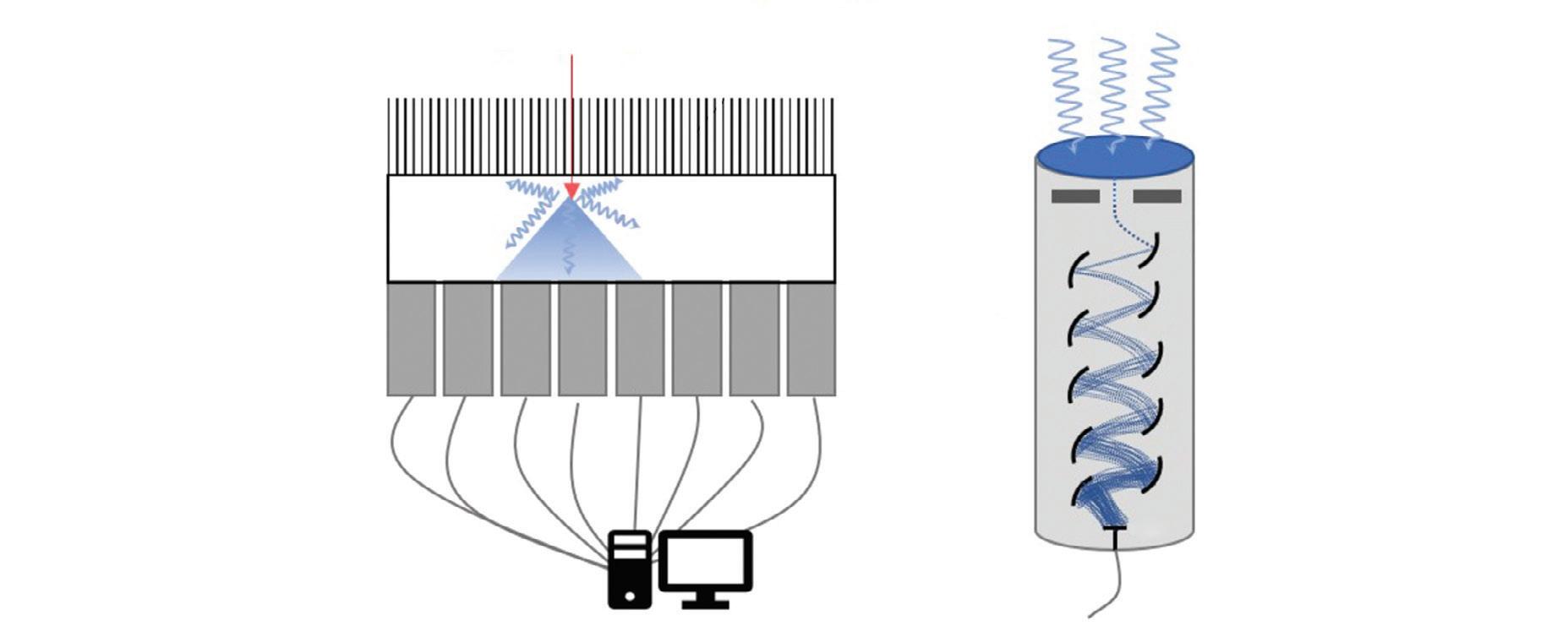
The most commonly used detector material is the scintillation crystal that converts energy from each gamma ray (high-energy photon) into many low-energy photons, which are subsequently converted to an electronic signal using a light sensor (Fig. 1.1).3
Scintillation Crystals
Scintillation materials emit light (low-energy photons) when they interact with gamma rays. Desirable features in a scintillator are a high density to ensure a high efficiency
for interacting with gamma rays, a high light yield (number of information carriers), good transparency to those photons to ensure a high energy resolution, and a fast response to process each event quickly to be ready for the next interaction (low dead time). Most SPECT scintillation detector–based systems use sodium iodide (NaI) inorganic ionic crystals or, less commonly, cesium iodide (CsI) crystals. NaI crystals yield 41,000 photons per gamma ray MeV, whereas CsI crystals yield 64,000 photons per MeV.4 High numbers (N) of scintillation photons are desirable because the gamma ray measurement uncertainty s is governed by Poisson counting statistics for which s2 is proportional to N.
Light Sensors
Scintillation detectors produce an electronic signal proportional to the energy of each gamma ray by coupling a light sensor to the scintillation crystal. A photomultiplier tube (PMT) is a light sensor that contains a photocathode and series of dynodes (see Fig. 1.1). The photocathode absorbs scintillation photons and relays their energy to ionized electrons. These primary electrons are focused onto the first dynode in the PMT where their kinetic energy ionizes secondary electrons. Electric fields within the PMT accelerate the resulting electrons through a series of dynodes under a vacuum. The number of electrons is increased approximately five-fold after each interaction with a dynode. With 8 to 12 dynodes in a typical PMT, the total signal amplification is approximately 106 or 107. The electrical signal read from the back of the PMT is proportional to the amount of incident scintillation light, which is, in turn, proportional to the energy of the detected gamma ray. The PMT signal is, therefore, calibrated to provide a measurement of the gamma ray energy.
For some applications, solid-state light sensors are desired. Avalanche photodiodes (APDs) are silicon-based semiconductors across which a high electric field (.107 V/m) is used. Inbound photons liberate an electron in
the material to which the electric field provides enough energy to produce an additional electron-hole pair. Subsequent electrons are also accelerated to create more electron-hole pairs. This signal amplification is known as the avalanche effect . Increasing the electric field increases the amount of amplification. The electronic signal obtained from an APD, whose electric field is set to generate an avalanche, is proportional to the number of scintillation light photons detected. APDs are typically around 2 mm thick and have an area up to 30 mm 3 30 mm. Higher electric fields lead to an uncontrolled avalanche, allowing APDs to be used like a Geiger-counter such that the signal is independent of the number of photons that interact within the time it takes the detector to reset. Silicon photomultipliers (SiPMs) use arrays of a lot of very small area APDs (side length of 20 to 100 m m) in Geiger-mode to count the number of interacting light photons. The electron signal obtained from a SiPM is proportional to the number of APD cells activated, which is proportional to the number of scintillation light photons, which is, in turn, proportional to the energy of the detected gamma ray. The detectors must be calibrated to the specific expected gamma ray energy. This is important because, for higher gamma energies, there is an increased potential for event pile-up, which is when more than one scintillation photon interacts with an APD cell that can only count one photon at a time. Event pileups produce less APD cell activations than there are scintillation photons which can lead to the underestimation of gamma ray energy.
Most clinical SPECT systems use PMTs; however, some small animal systems or evolving research cameras may employ APDs or SiPMs. Solid-state light sensors are much smaller than PMTs, allowing for compact camera designs. When used with appropriate electronics, they can also be used in magnetic fields to enable the development of hybrid SPECT–magnetic resonance imaging (MRI) cameras, which is something that is not possible with PMTs.
Scintillation crystal
PMT array
Readout electronics and signal processing
ray Scintillation light
Photocathode
Focusing electrode
Primary electrons
Secondary electrons
Dynode
Vacuum
Anode
1.1 A standard scintillation detector. A gamma ray passes through the collimator and interacts with the scintillation crystal to produce scintillation light. The light photons spread within the crystal before being detected by an array of photomultiplier tubes (PMTs), which convert the light into an electrical signal at their photocathodes. The electrical signal is amplified through a series of dynodes. The signals from the array of PMTs are processed to determine the location and energy of the incident gamma ray.
FIG.
Parallel-hole collimator
Gamma
A scintillator paired with a PMT produces around 10 information carriers per keV of gamma ray energy. With a scintillator and solid state light sensor, around 29 carriers are produced per keV, allowing for improved energy resolution.4
Position of Interaction
The scintillation light from the detector crystal spreads from the point where the gamma ray interacts with the crystal. The spreading light shower illuminates more than one light sensor and the amount of light seen by a light sensor depends on its distance from the point of interaction. Using the known positions of the light sensors and a weighted combination of the signals measured by each, the location of the point of interaction of the gamma ray with the scintillation crystal can be calculated.5 The energy and location of the detected gamma ray are recorded and used to build up a 2D picture, also known as a “projection,” of the distribution of the radioisotope in the patient.
Cadmium Zinc Telluride Detectors
Cadmium-zinc-telluride (CdZnTe or CZT) semiconductor detectors directly convert gamma rays into electronic signals. CZT material is sandwiched between a front cathode and an array of pixelated anodes at the back surface. Incoming gamma rays ionize the CZT material to create e-h pairs within the detector. A high voltage is applied across the detector to collect electrons at the anodes. The voltage is set high enough to minimize recombination of electrons with holes, which could result in lost signal and a perceived reduction in the energy of the detected gamma ray. Nevertheless, it is not chosen to be high enough to induce Geiger breakdown like SiPM light sensors do. Thus, the charge collected at an anode is assumed to be proportional to the energy of the detected gamma ray. The single step conversion of gamma ray energy produces around 333 information carriers per keV. Even with some lost signal from charge recombination or lateral drift of charges to spread the signal between anodes, the energy resolution of CZT detectors (6% at 140 keV) is much better than that of scintillation detectors (10% at 140 keV for NaI-PMT).6,7
COLLIMATORS
Gamma rays from radiotracers in the patient spread out in all directions such that a 2D image formed on a bare detector would be irrevocably blurred. To provide a clear 2D view, we need information about the trajectory of the detected gamma rays. Collimators provide this context by restricting the angle of the gamma rays that are allowed through to the detector. With a collimator mounted to the surface of a detector, the gamma rays that are detected are known to have traveled a path within a narrow range of angles.
Parallel Hole Collimaters
Parallel-hole collimators allow for the detection of gamma rays traveling perpendicular to the detector surface. The
collimator has a densely packed array of parallel holes in a high-density material. The diameter of the holes, spacing between holes, and collimator thickness (or hole depth) dictate the resulting spatial resolution and the sensitivity for detecting gamma rays. Fine detail (better spatial resolution) is provided by thick collimators with small-diameter holes. This arrangement, however, drastically limits the number of gamma rays detected from a source. In cardiac imaging, low-sensitivity collimators can mean needing higher patient doses or longer imaging times to acquire sufficient counts. Conversely, when using large holes or thinner collimators, the sensitivity is improved but at the cost of a blurrier image (Fig. 1.2A). Collimators are described based on the energy of the isotopes they are designed to detect (isotopes used in cardiac SPECT are typically low energy) and their sensitivity/resolution. A
Source object
Parallel-hole collimator
Detector
Image brightness
Image orientation
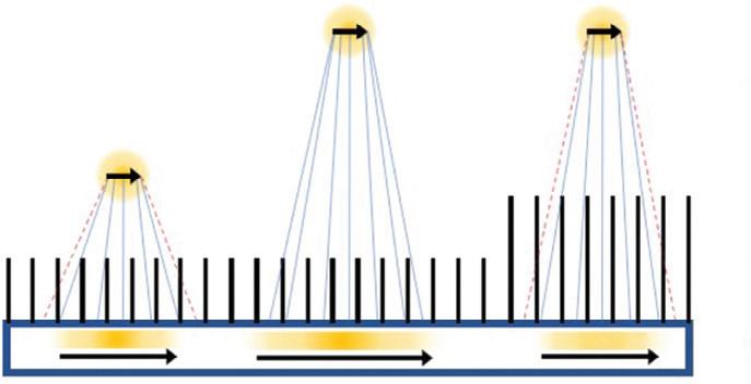
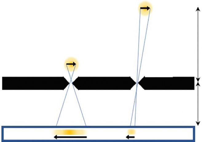
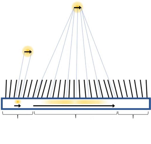
FIG. 1.2 Collimator response: brightness and orientation of a detected image. (A) With a parallel-hole collimator, the image is more blurred for an object farther from the collimator. For a fixed object position, image blurring is lessened (better resolution) by increasing the collimator thickness but brightness (sensitivity) decreases. (B) With a pinhole collimator, the image is inverted relative to the object and magnified with a factor of m 5 f/o, where f is the pinhole-to-detector distance and o is the object-to-pinhole distance. Image brightness (sensitivity) decreases with increasing distance of the object from the pinhole. (C) With a multifocal collimator, the orientation of the image relative to the object is the same but the magnification, spatial resolution, and gamma ray sensitivity vary greatly with object position. The image of an object in the divergent region is minified, but one in the convergent region is magnified.
Pinhole collimator
Converging collimator
Diverging collimator
common collimator for cardiac imaging is the low-energy high-resolution (LEHR) collimator.
The sensitivity for detecting gamma rays is approximately uniform for varying distances of sources from a parallel collimator. The spatial resolution degrades linearly with distance of the source from the plane of the detector so that an object close to the detector-collimator will be resolved more clearly than an object farther away8 (see Fig. 1.2A).
Pinhole Collimaters
A pinhole collimator has a single hole. Detected gamma rays that have passed through the aperture produce an inverted image of their source (see Fig. 1.2B). Depending on the ratio of the pinhole-to-detector and detector-tosource distances, the image can either be magnified or minified. Magnification is particularly helpful for small animal imaging systems, whereas minification can allow small-detector-area cameras to avoid truncation of the heart in dedicated cardiac imaging. The spatial resolution of a pinhole collimator-detector depends in part on the aperture diameter and the amount of magnification. The sensitivity for detecting gamma rays depends on the diameter of the pinhole aperture but also on the distance and angle of the source with respect to the pinhole. The sensitivity can be very high for sources close to the pinhole but decreases for gamma rays incident from wider angles and for sources at greater distances. Like the parallel-hole collimator, spatial resolution degrades linearly with distance of the source from the pinhole.8
Multifocal Collimaters
Multifocal collimators are used for specialized applications to improve both sensitivity and resolution compared with traditional parallel-hole collimators using a combination of converging and diverging holes with various focal lengths in a single collimator (see Fig. 1.2C). The design most relevant to cardiac imaging has holes at the center of the collimator that converge toward the heart and therein sample the heart location more for improved sensitivity and magnify the heart onto the detector for improved resolution compared with parallel hole collimators. Holes closer to the edges of the collimator diverge more the closer they are to the edge until they are nearly parallel, which provides information about surrounding structures and avoids truncation artifacts.9
SYSTEM DESIGNS FOR CARDIAC SPECT IMAGING
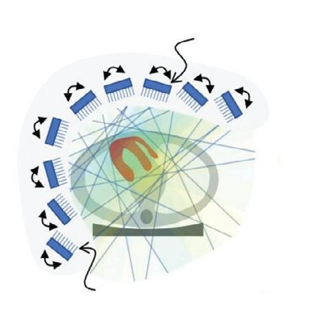
Rotating Gamma Cameras
The conventional camera design for SPECT imaging uses a scintillation detector head, with a parallel-hole collimator, attached to a gantry, which allows the detector to be rotated around the patient to acquire multiple different views (Fig. 1.3A). The patient lies on a table near the center of rotation of the system and is the axis about which the detector is rotated during acquisition. The axial
PMT detector array
Parallel-hole collimator CZT detector
FIG. 1.3 Single photon emission computed tomography (SPECT) cameras commonly used for cardiac imaging. (A) Standard dualheaded SPECT camera with parallel-hole collimators with the heads in the 90-degree orientation. Systems with one or three heads are also used. (B) The central arc of nine pinholes in the Discovery NM530c dedicated cardiac SPECT camera. (C) An arc of nine detector heads with parallel-hole collimators, which swivel to scan the field of view in the D-SPECT camera. (D) A dual-headed SPECT camera with multifocal cardiac (SMARTZOOM) collimators as used with IQ SPECT. CZT, cadmium zinc telluride; PMT, photomultiplier tube.
field-of-view (FOV) of modern SPECT cameras is usually about 40 cm, completely covering the heart. The table and patient thus remain stationary during the entire SPECT acquisition. The orientation of the patient is usually either supine or prone on the table with the axis of rotation of the camera perpendicular to the transverse plane of the patient.
A 3D image of the radioisotope distribution can be created from a set of 2D images taken over a range of angles around the patient through image reconstruction. To accurately and consistently move the detector around the patient, it is mounted on a motorized rotating gantry ring. As it rotates, the detector head can also be moved in or out to optimize the distance of the detector from the patient. Most commonly, a parallel-hole collimator is used for which resolution gets worse with increased patient-todetector distance, so the detector is kept as close to the patient as possible.
With a single-head gamma camera, only one view is acquired at a time. Adding additional detector heads to the gantry allows for the acquisition of multiple views simultaneously and so increases the sensitivity of the system. Cameras with two detector heads are common, and threehead systems are also available. The acquisition orbit of the camera is usually from left posterior oblique (LPO) through the left anterior oblique (LAO) to right anterior oblique (RAO) position. A 180-degree arc of views is needed for 3D image reconstruction and, because the heart is located on the left side of the body, the LPOto-RAO rotation provides the lowest attenuation by the
PMT detector array
Multifocal collimator
Parallel-hole collimator
Pinhole
CZT detector
patient tissues and thus the strongest signal from the myocardium. Using a two-head system with the heads 90-degrees apart allows the full 180-degree data set to be acquired with a single 90-degree rotation of the camera.
One additional feature available on some cameras is the ability to tilt the detector in the caudal direction. This feature is sometimes helpful to allow for the acquisition of true short-axis (SA) views during ECG-gated blood-pool planar studies.
Dedicated Cardiac Systems
In addition to the conventional general-purpose gamma camera, a number of novel camera designs are now available for cardiac SPECT imaging.10 The two most popular of these dedicated cardiac cameras both use the same CZTbased detector module but with a quite different number and arrangement of the modules.
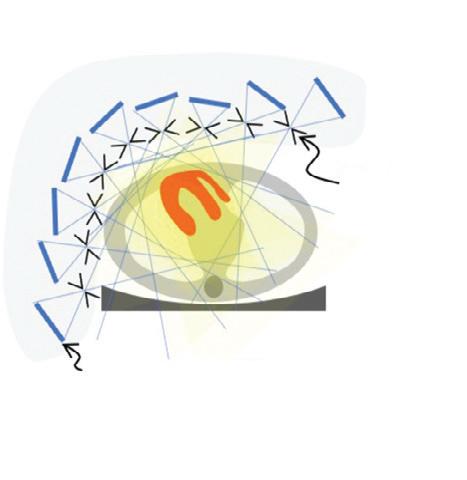
The multipinhole camera (Discovery NM530c, GE Healthcare) uses a set of 19 detectors.11 Each detector consists of four CZT-modules arranged in a 2 3 2 array to create a square 8 cm 3 8 cm panel. The detectors are aligned on three parallel arcs around the patient (from LPO to RAO) with nine detectors in the central arc (Fig. 1.3B) and five detectors each on the inferior and superior arcs. Each detector uses a single-pinhole collimator and the 19 pinholes all focus on a common point. By centering the patient’s heart within the 19-cm diameter FOV, the system provides a fourfold sensitivity gain over a conventional dual-head gamma camera. The system design uses the minifying properties of the pinhole collimator to ensure the image of the entire heart fits within the size of the detector.
A second dedicated cardiac design (DSPECT, Spectrum Dynamics) uses nine column detectors (Fig. 1.3C).12 Each detector consists of a 1 3 4 array of CZT modules and is 4 cm in the patient transverse direction and 16 cm in the axial direction. The columns oscillate during acquisition to fan over the entire FOV in a period of 3 to 6 seconds. A short prescan is used to define the position of the heart. During the full scan, the columns oscillate nonuniformly, spending more time directed at the heart but still providing some information about the rest of the patient as well. Each detector uses an ultrahigh-sensitivity parallel-hole collimator that is matched and aligned with the 2.5-mm detector pixels. The large collimator bore diameter causes a loss in spatial resolution, but this resolution loss is recovered by careful modeling of the collimator during image reconstruction. The raw sensitivity gain of the system is 8 to 10 times that of a dual-head conventional camera.13 Another innovation of the DSPECT system is that it uses a patient chair so that the patient is imaged in an upright position, rather than the conventional supine position. The chair can also be tilted to allow for semireclined imaging, which provides a second patient orientation and helps to assess for attenuation artifacts.
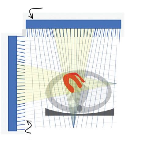
A third approach to cardiac imaging uses a conventional dual-head gamma camera but with a specially designed multifocal collimator and acquisition protocol (IQ SPECT, Siemens10,14). The multifocal collimator is configured as a converging collimator in the center of the detector, but the
focal length increases with increasing distance from the center so that by the edge of the detector, it is behaving like a parallel-hole collimator (Fig. 1.3D). This design has increased the sensitivity in the center and reduced sensitivity toward the edges of the detector FOV. Using a cardiocentric orbit that maintains the position of the heart near the most sensitive position for the collimator and careful modeling of the collimator during reconstruction to correct the spatial distortions caused by the collimator allows for the reconstruction of images that have similar resolution but a fourfold increase in sensitivity over conventional dual-head cameras.13
FACTORS AFFECTING IMAGE QUALITY
Many different factors can influence the quality of cardiac SPECT images and degrade the accuracy of cardiac imaging. Some are related to patient physiology, such as consumption of caffeine or ability to reach target heart rate during exercise, whereas others are addressed by quality assurance programs that ensure optimal camera performance and proper radiotracer formulation. Four factors that are always present with SPECT imaging are attenuation, scatter in the patient tissues, patient motion, and noise in the detected data. Please also see the discussion in Chapter 5.
Attenuation
When the radioisotope of the tracer in the myocardium decays, it emits gamma rays. For 99mTc-labeled tracers, the primary emission is a gamma ray with 140 keV. Although many gamma rays pass unimpeded out of the patient, a substantial number interact with the patient tissues. The interaction can be a photoelectric absorption wherein the gamma ray is completely absorbed by the tissues and disappears. Or, more commonly, the gamma ray can Compton scatter off of the tissues, resulting in a reduction in energy and a change in direction. Attenuation refers to any interaction with tissues. The probability of attenuation depends on the energy of the gamma ray and on the length, density, and composition of the material that the gamma ray is passing through. The intensity, I, of a beam of radiation with initial intensity Io, which passes through a thickness of material (x) with a linear attenuation coefficient m is I 5 Io exp (2m x).
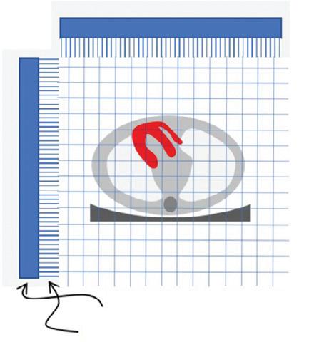
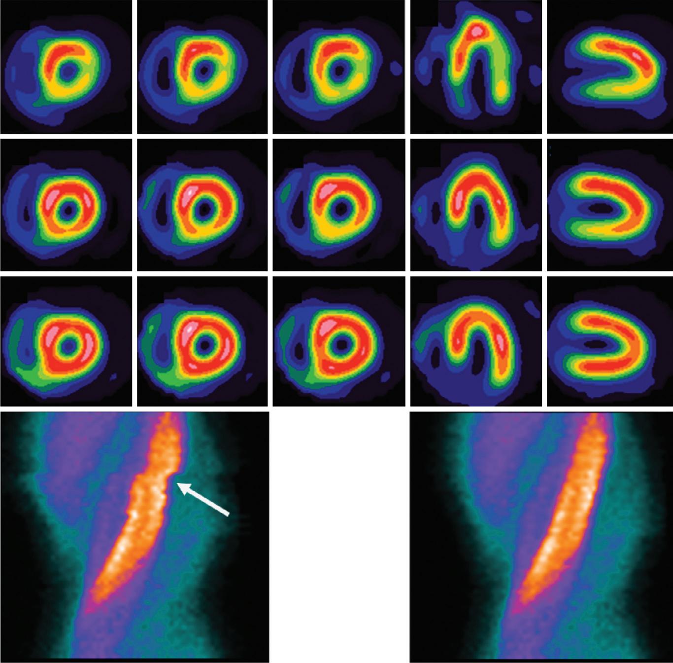
For 140 keV gamma rays, water has an attenuation coefficient of 0.154 cm 1, so that the half-value thickness for water is 4.5 cm (the thickness of water required for I 5 0.5 Io). More than 75% of the signal is attenuated if the source is at a depth of 10 cm. Attenuation is thus a significant problem for cardiac SPECT imaging. Differing amounts of attenuation from radiation passing through different types or amounts of tissue before arriving at the detector can lead to image artifacts. Common attenuation artifacts stemming from partial shadowing of the heart by breast tissues or subdiaphragmatic structures (Fig. 1.4) can mimic the appearance and location of cardiac disease and make interpretation difficult.15
One solution is to compensate for attenuation during the image reconstruction, but other approaches can also aid interpretation in the presence of suspected attenuation artifacts. Matching reduction in uptake at both rest and stress could be either attenuation or infarct. If an infarct, there is a high probability that the motion of the wall in that region would be affected. Thus evaluation of wall motion using ECG-gated images can help differentiate attenuation from disease.15–17 Another approach is to acquire a second set of images with the patient in a different position (e.g., both supine and prone images).15,18,19 Moving the patient will change the configuration of patient tissues between the heart and the detector and alter the attenuation pattern. A reduction in uptake that is present in both positions is more likely to be a real defect because of disease, whereas a reduction that normalizes in images from a different position is more likely to be the result of attenuation.
Scatter
When gamma rays Compton scatter as they pass through the patient tissues, they lose some of their energy and change their direction of travel. The energy loss is larger for larger scattering angles. Although the SPECT camera measures the energy of the incident gamma ray, the energy
resolution of this measurement is only 10%. The typical photopeak energy window used for 99mTc gamma rays is 7.5% to 10% on either side of the emission energy. This means that an incident gamma ray with a true energy of 126 keV can still have a 50% chance of being detected in the photopeak window. In clinical imaging, the number of scattered gamma rays accepted in the photopeak window is between 30% and 40%.20 Once accepted within the photopeak window, there is no distinction made between gamma rays with 140 keV and those with 126 keV.
Standard reconstruction algorithms assume that the source of any detected gamma ray lies along the line it was traveling on when it was detected. This is not the case for scattered gamma rays that changed direction before being detected. A Compton-scattered gamma ray with an energy of 126 keV (instead of the expected 140 keV) will have scattered by 53 degrees. Scattered gamma rays, therefore, are mispositioned by the reconstruction algorithms, leading to an apparent spreading of the activity distribution. In cardiac imaging of hypoperfused areas surrounded by normal myocardium, scattered radiation fills in the low count region and decreases contrast, leading to a reduction in the perceived severity of a defect. In addition, scatter from extracardiac sources can cause apparent increases in uptake of adjacent myocardial walls. This becomes more visible when the overall effects of attenuation are removed.21
FIG. 1.4 Patient motion and attenuation can degrade images. In this example, transverse patient motion introduces a discontinuity into the sinogram (white arrow) that causes reduced apparent uptake in the lateral wall and distortion near the apex as seen in the short-axis and horizontal long-axis (HLA) views. Diaphragmatic attenuation leads to a decrease in apparent uptake in the inferior wall, seen in the vertical long-axis (VLA) views, which is corrected with computed tomography-based attenuation correction (AC).