The next important step in show window wiring is the proper fusing of circuits. The fuse is to the lighting wire what the safety valve is to the steam boiler. A fuse is composed of a fusible metal, which contains lead, zinc, etc., and becomes fusible at a certain degree of temperature. The fuse is supposed to be “the watch dog” of safety. Ninety-five per cent of the electrical fires are caused by improper fusing.
My advice to the amateur is to apply to the nearest office of the National Board of Fire Underwriters for a copy of the rules on incandescent wiring. They may be obtained for the asking.
THE TRANSFORMER.
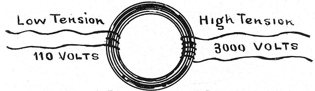
Usually the electric fluid (?) is conveyed into the building from the alley, where the high tension wires are strung, carrying a pressure of 2,500 to 3,500 volts from this line. By the aid of a “transformer” the current is reduced to a pressure of 110, 105 or 50 volts, as required, entering the building, when it is conveyed to a double-pole switch; that is, a switch which cuts off both positive and negative wires at the same instant.
The “transformer” is a device for reducing the current from one potential or tension to another, and consists of a ring of many turns of insulated wire; the high tension wire is then wound around and through this ring several turns, and the low tension wire carrying the current into the building is wound around the opposite side of the ring in like manner. The difference in pressure is controlled by the number of turns around the ring on either side, as shown.
All the wires being insulated, the reduction is made by “induction” only. The size of the wire makes no difference in the voltage or pressure, but it makes all the difference in the “amperes” or quantity used to supply the building.
The electric light company will supply a sufficiently large wire from transformer to switch; the firm does the remainder of the wiring.
FEEDERS.
From this large double-pole switch (which is the main cut-off) radiate “feeder” wires to the various parts of the building, to supply the lamp circuits. These feeders have to be carefully gauged according to the number of lamps, or rather, amperes, they are required to carry, in order to avoid resistance in the wire; or in other words, must not crowd the carrying capacity of the wire, or the resistance will make the wire hot and might cause fire.
A “feeder” to the circuits for fifty incandescent 16-candle power lamps should be of somewhat higher capacity, say a No. 10 Brown & Thorp Gauge (B. & S. G.) which has a safe carrying capacity of thirtytwo amperes or sixty-four 16-candle power lamps, allowing one-half ampere to each lamp; a No. 12 B. & S. G. wire is allowed to carry twenty-three amperes, or about forty-five 16-candle power lamps; No. 13 B. & S. G. wire is allowed to carry sixteen amperes, or about thirty 16-candle power amps.
The “feeder” should have considerably more carrying capacity than is required in order to permit the addition of extra lights, as occasion may require, and to provide for the addition of extra window lights, if there be not a special feeder for the purpose.
The feeder wires are tapped for lamp circuits by a branch block carrying a fuse for the protection of the circuit. The construction and operation of the branch block, or cut-out, will be understood at once on inspection. The fuse here is the important part; it must be of smaller carrying capacity than the wire it is to protect, and not depend upon the amount of current in the feeder; thus, a No. 10 B. & S. G. might be protected with a 20-ampere fuse (forty lamps, sixteen candle power), or with a 25-ampere fuse, leaving a margin of seven amperes, the wire being allowed to carry thirty-two amperes. It will be understood that “open work” is meant in every case, and wires that are concealed are not allowed to carry so much. The No. 12 wire B. & S. G. is allowed twenty-three amperes, and would be protected by fuse of fifteen to twenty amperes capacity.
The lamp circuits from feeders are in many cities restricted to a certain number of amperes, usually six to ten, or say from ten to twenty lamps (sixteen candle power). Each of these circuits must be protected by its own fuse and have an independent switch. All fuse boxes must have their porcelain cover kept on, and no inflammable material allowed near them. “Twin wires,” or two wires encased, are objectionable.
Drop cords are not allowed except for drop lamps, and must be protected by one-ampere fuse in rosette or cut-out. All wires where joined must be soldered—to prevent an arc forming by making the path of the current continuous or tight.
It is well for the beginner to know that a current of 110 volts does not kill, though it might make the recipient seriously ill. Therefore, be careful not to get yourself in the path of the current. Never touch both naked ends or openings in wires at the same time, nor stand upon the ground while working live wires. Always stand on some non-conductor, a dry board, for instance. The inexpert can always protect himself by disconnecting a fuse behind him both sides; or, better, open the “main cut-off” or first switch.
CONNECTIONS.
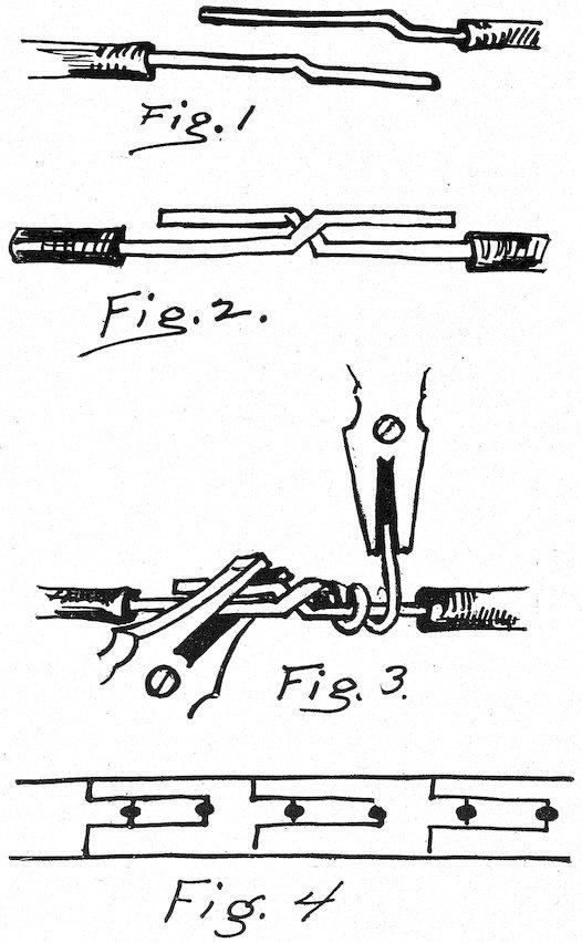
When your design is wired and set up in your window, your next step is to connect it to your “cut-out.” You will find two wires leading from it; to these you connect the two wires leading from your design. It is not necessary to solder this connection; simply remove sufficient insulation and twist the wires together tightly.
There is a way to do this that every one should know, and I will tell you how to make a
WESTERN UNION HITCH.
After removing the insulation from the wires at the ends to be connected, bend the wires as in Fig. 1, lay them together as in Fig. 2, then with a pair of pliers hold one side, and with another pair twist the end around the lead wire tightly and closely, as in Fig. 3. When this is done hold the twisted wires with pliers and repeat the twisting process on the other side. This is a perfectly safe connection, and does not waste electricity as does a loose joint.
DIFFERENT VOLTAGES.
Sometimes it happens that your electric system is of higher voltage than you need use in special work; for instance, you may have a 220volt circuit, whereas 110-volt lamps are amply strong for your work; or again, you have a 110-volt circuit, and want to use a number of small lamps, 1-candle power, for example.
These are usually of lower voltage, fifty-five or thereabouts.
In these instances we resort to a method known as wiring in series, which is done as in Fig. 4.
Of course the number of lamps to a series is to be governed entirely by the voltage, and the trimmer must resort to his own judgment in determining this.
You will see by the diagram in Fig. 4 that you have two lights for each connection with your lead wires, therefore, if using a 220-volt circuit and 110-volt lamps you have each connection using the full 220 volts, otherwise your lamps would soon burn out, as every connection must consume as many volts as your circuit carries.
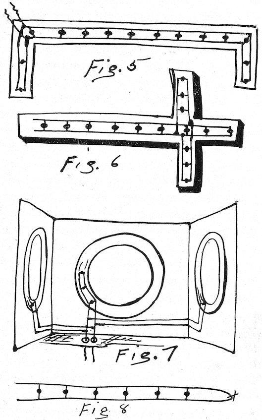
Special Designs.—These few instructions answer for a single string of lights, such as a circle, arch, cornice, etc., where your leads run uninterruptedly from first to last lamp; but “how about a design that is impossible to wire that way?” you ask. It is simple, and I have made a few diagrams to illustrate the method employed.
You may have a cornice about your windows, and must bring your wires from the corner. Fig. 5 will show how to do it. A cross, or such designs as have two breaks, are wired as in Fig. 6.
Again, you may wish to use more than one design in a window; for example, you may have three circles, one at back and one at either side. Fig. 7 shows the easiest method. These principles apply to many varieties of designs, and it is only the principles I am endeavoring to make plain. And now I will give a few hints or, better yet, some don’ts which will be valuable for amateurs.
SOME “DON’TS.”
Don’t be negligent in handling your connections. Insulate every joint, and don’t leave loose joints; they consume too much current.
Don’t cross wires that are insulated without bushing the overlying wires, and never cross uncovered wires.
Don’t bring a wire through the floor or back of window without using clay bushings; that’s what they are for.
Don’t run wires (as in Fig. 8) without using a lamp, or cutting wires where X is marked; it saves a short circuit.
Don’t let the wires to your lamps touch brass, except under the screw.
Don’t attempt to connect your design to your “cut-out” until you are sure your switch is open. You may short circuit yourself. It is not necessarily fatal, but is decidedly unpleasant.
Don’t handle live wires; 110 volts won’t kill you, but through carelessness you may some day touch a stronger circuit. Practice caution.
Don’t leave an uncovered wire to show in your window. If you suspend a design, wrap the wires with the same color as your background.
Don’t imagine you are an electrician because you can run a string of lights. Keep digging away; you’ll learn something every day.
Don’t try to do all kinds of joint soldering by heating the wires merely. When you become a little more accustomed to the work, get a larger tool kit, and among the first things get a soldering iron. In many places it is necessary.
LETTERS IN ELECTRIC LIGHT.
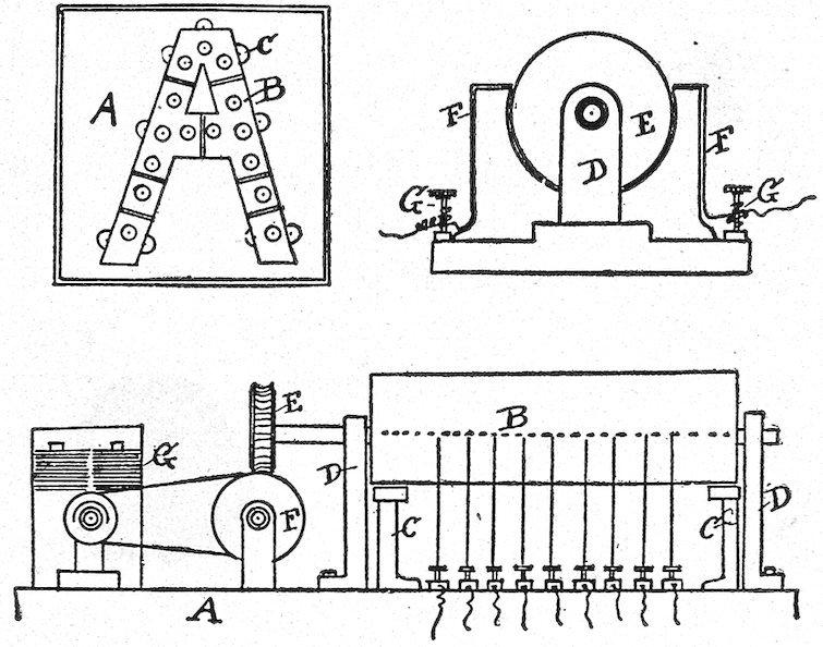
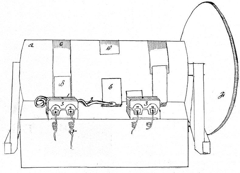
In the following illustrations are shown plans of a sign to be electrically illuminated. The electrical work is necessarily done in the electric working shops, but as many illuminated signs are being used nowadays, the description may be useful to decorators who contemplate putting in something of the kind. In the first figure the letter is on a casing, A, having a back or support carrying incandescent lamps in channels. The form of the letter is sheet metal and is set-screwed to the base piece at the places marked C. The disks B are plate glass colored to conform to the requirements. The commutator is shown in the other figures. In the first, E is a wood cylinder, which turns in bearings, D. F F are spring contractors, and G G wire connections which join those of the lights. Another view is in the next drawing, in which the cylinder is B, bearings D and spring contractors C. The cylinder is driven by a small electric motor, G, through a reduction gear, consisting of a train of wheels or worm gearing, as at F and E. The spring contacts are electrically joined to the terminals of the lights. The terminals are joined by a combined return to one pole of the source of electric supply, and the other pole is connected to the contact pieces. The rotation of the cylinder consequently breaks and joins the circuit as desired, producing alternate changing of the lights and colors, resulting in attractive effects.
THE WEBER COMMUTATOR.
FIG. 1.
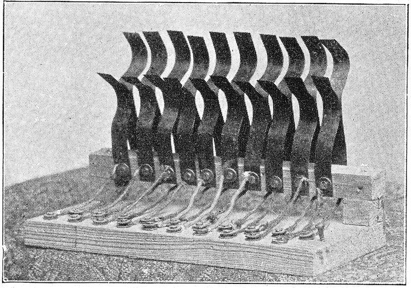
Fig. 1 is end view. H is a wooden cylinder six inches in diameter and twelve inches long (length is optional according to number of lights), this, as well as all other bearings, run on bearings of curtain fixtures. G is pulley wheel connected with reducer in Fig. 3, D are projections of soft rubber ¼ inch thick placed on cylinder H, and work as follows:
When D reaches E it forces E to the left and forms a contact at F F, thus closing the line and causing lamp or lamps to burn. The position of D on cylinder, and length of same, must be determined by the length of time the lamp or lamps continue to burn and when they shall burn.
The distance from A B to B is 5¾ inches, from A C to C is 7¼ inches.
F F are made of spring copper cut in strips ⅜ of an inch wide and bent to shape, then fastened in base with screws and washer.
FIG. 2.
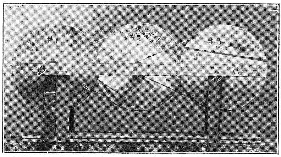
Fig. 2 shows front view of commutator and needs no explanation. The above can be operated with water, motor or electricity; but where electricity is used it becomes necessary to reduce speed of motor (which is 2,200 revolutions) to about 40 or 50 revolutions; this is done by building the reducer as shown in Fig. 3.
Fig. 3 shows machine made at an outlay of labor only. Procure six tobacco pail lids, join them face to face with screws and you have three grooved wheels. Make axles of curtain poles twelve inches long, then make frame, again using curtain fixtures as bearings.
3.
FIG.
Attach motor to No. 1, then from axle of No. 1 run belt to No. 2, from axle of No. 2 run belt to No. 3, then attach axle of No. 3 to pulley G on cylinder and you have a machine on which you can operate from 1 to 100 incandescent lamps alternately.
The Weber commutator is very inexpensive, and has been made by a decorator with an outlay of only fifty cents for the three parts.
THE REYNOLDS FLASHER.
The most reliable machine we now have is one manufactured by a Chicago firm, which is perfect in its construction and operation and will not break down or cause danger from sparks. The expense is about fifteen dollars and the adjustment is so easy that any one can operate it.
A CHEAP HUB SWITCH.
No doubt every one has seen revolving wheels, stars, pyramids, spiral stairs, etc., strung with lights, and many have envied the man who had the facilities for this work; but by following these instructions they can make an appliance that will do the work perfectly.
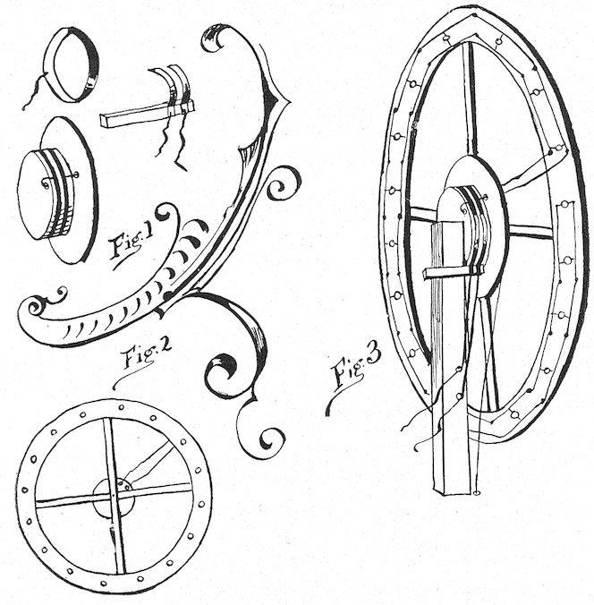
First make a pulley wheel twelve inches in diameter; then make two circles of one-inch wood six inches in diameter; nail together and fasten in exact center of pulley; insulate the 6-inch circles perfectly.
Next take two strips of spring copper three-eighths inch wide, and make two hoops to fit snugly over the insulation and to each hoop fasten a wire eighteen inches long; then put your hoops on your 6inch circles about one inch apart, taking care to have them even and tight.
Bore a hole through pulley wheel, and run wire from hoop nearest it through hole; then bore a hole through 6-inch circles and pulley, and run the other wire through it. Use bushings in holes, and insulate uncovered wires. Next take two pieces of copper threeeighths inch wide, six inches long, bend in half circles, attach wire to end of each, fasten to a piece of 1×2, so they will form contacts with copper bands on circles.
Fig. 1 shows band of copper, two half circles on 1 × 2, and pulley when finished.
Now suppose you want to use revolving wheel on pivot. Fasten your appliance in center of wheel, run wires from lamps to wires running through pulley and connect them; then when your wheel is in position, fasten piece of wood with two half circles so each presses tightly on one of the copper bands; connect the wires from half circles to wires from switch, and as your wheel revolves you have a steady contact.
Fig. 2 shows front of wheel, and 3 shows wheel from rear with half circles in position.
For a pyramid or such fixtures simply fasten your appliance to bottom or top as serves your purpose best.
Make your work as near perfect as possible, so the half circles never leave the bands, and exercise great care in insulating, for, while neglect does not always result disastrously it is well to be on the safe side.
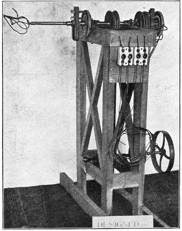
THE RUBENS DOUBLE-REVOLVING EFFECT.
The idea is novel and simple. The construction of this machine is inexpensive. Go to any machine shop and have them bore out a piece of shafting so that one will fit into the other snugly. The contact plates are made of copper, lined with asbestos, mounted on wooden circles. In fact, the entire machine can be built for $12. There is no limit to designs that can be made for this arrangement. The novelty of two large pieces revolving in opposite directions, apparently from the point of a single shaft, is in itself a worthy attraction in any window. You will observe in photo that there are two pulleys on main
shaft, also a countershaft below. One belt is up straight, the other belt is twisted so as to reverse either shaft. The large pulley on the countershaft is the main driver. The belt attached to this pulley leads to your motor or whatever power you wish to employ. This device is safe as well as simple, as you have ample room for cut-outs.
A—Inner shaft, ⁷⁄₁₆ inch diameter.
B—Outer shaft, 1³⁄₁₆ inch diameter.
C—Contact plate.
D—Holder for brushes.
E—Driving pulley for outer shaft.
F—Driving pulley for inner shaft.
G—Contact for feed, inner shaft.
H—Boxing for shaft.
I—Flange for inner shafting.
J—Flange for outer shafting.
K—Cut-outs.
L—Binding posts for outer shaft.
M—Feed wires.
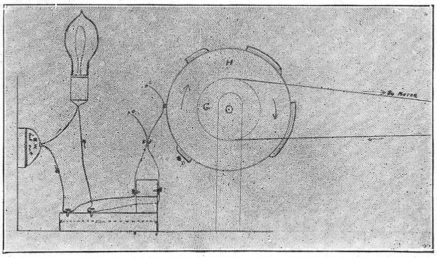
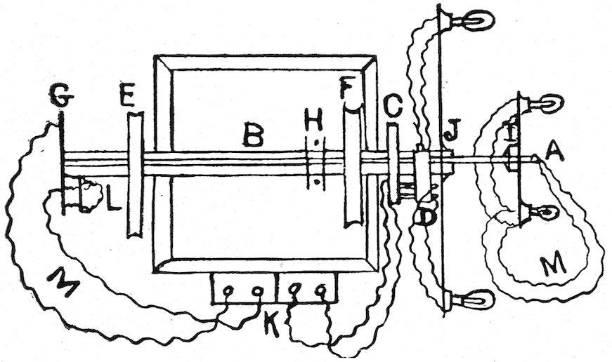
THE TYLER AUTOMATIC SWITCH.
A is a wooden cylinder, twelve inches long and six inches in diameter. B is brush made of three layers of copper, and is screwed down at lower end, No. 1, so as to work as a spring. C is piece of copper one-half inch wide fastened around cylinder, and comes in contact with B, so as to make one feed wire run to switch. D is piece of copper running one-third of the way around, and comes in contact with another brush, E. Then fasten a small piece of wire from C to D that carries the current to No. 2, while E is on copper. The other feed wire is direct from main circuit to window. F is pulley wheel running to reducer. No. 3 is fuse blocks, which can be used and are much safer than without. This switch cost me twenty-five cents. Of course, I am my own electrician. It will cost no more to any one, as it is very simple.
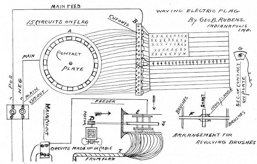
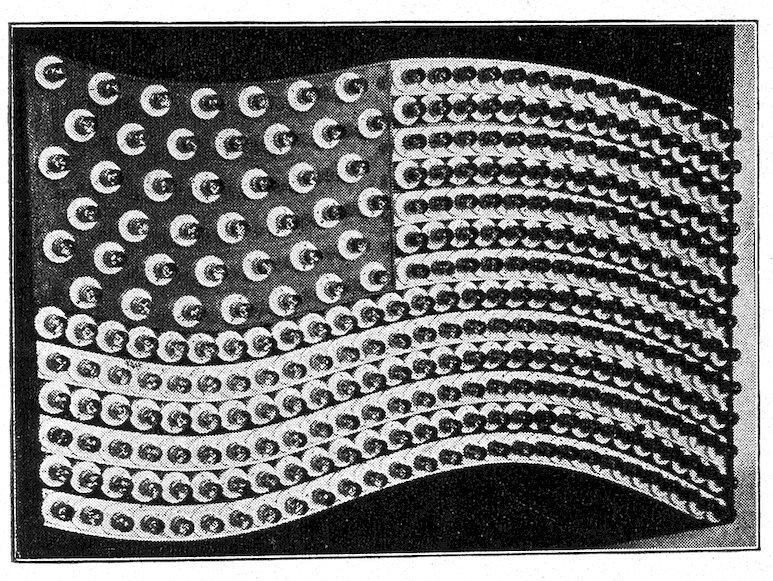
HOW TO MAKE AN ELECTRIC WAVING FLAG.
This would appear to the uninitiated as a hard one to build, yet it is one of the simplest electrical devices to construct.
First ascertain size of flag you want to make, as there is no limit to size. Build the body of your flag of thin boards, say half an inch thick. The next important thing is to outline on your woodwork an exact flag. Be sure you get the requisite number of stars and stripes. You are now ready to proceed to fasten on your sockets. I may further add here, the flag should not be square. Have a wave running through your stripes; saw out your edges (see cut) accordingly. You now have the general outline, as far as the flag is concerned.
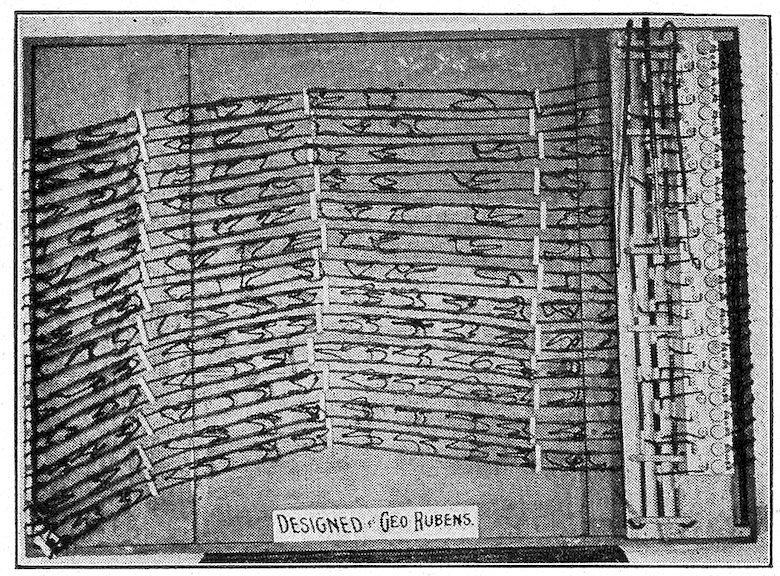
Now, then, for the mechanical part of it: Saw out two wooden disks, twelve inches in diameter, with a ⅞-in hole in the center. Next you procure a piece of slate, fourteen inches square. Take a compass and strike a 12-inch circle. By drawing your compass around several times, you will find it will cut a fairly deep line. You can then take a hammer and by a few light taps break the square edges of your slate, leaving a perfectly round disk of slate. Next, you want a ⅞-inch hole in the center of the slate. Now mount this on the wooden disk; next,
FRONT VIEW OF THE WAVING FLAG.
REAR VIEW OF THE WAVING FLAG.
cut the copper contacts and shape them the same as a keystone. It will require fifteen of them for that number of circuits. To each one of them solder a piece of No. 14 wire, as shown in cut G. Then bore the holes in the slate so that the wires will go through the back of the disks, as each wire must run from the disk to the flag; that is the negative side, and the positive side runs right straight from your feeder to the flag. For your second wooden disk cut out a copper ring, two inches wide, and fasten it securely to the wood, and solder your wire on the back of this, say a No. 8 wire. This will need contacts, as shown in cut E.
You next make a brush holder. This is a very simple arrangement. The holder is made of wood. Fasten brushes on securely, as shown in F of cut. When automatic switch is set up, it will appear as shown in cut E. Now fasten belt to pulley J, and then to motor, as shown in cut. This switch should make 300 revolutions per minute. As the brushes strike each section on the contact plate, it causes a wave of light to pass through that section of stripes or stars, as the case may be.
This may seem complicated and difficult, but I will venture to say, if you will study this ten or fifteen minutes you can without much difficulty or expense proceed to duplicate it.
Remember, each wire running from the disk must run into cut-out and from cut-out to the flag (see cut B). Also note how wire is soldered on in G. You can bunch and group all wires from A, and form them into a cable, as shown in cut I, as they are all of one polarity.
This description is for flag 4½ × 6 feet, to contain about 450 lamps. There are a number of different ways of producing this effect, but I have tried this one as described, and found it very satisfactory, likewise inexpensive to construct.