ATLAS OF Normal Radiographic Anatomy and Anatomic Variants
in the Dog and Cat
THIRD EDITION
DONALD E. THRALL, dvm, phd, dacvr
(Radiology, Radiation Oncology)
Emeritus Professor
Department of Molecular Biomedical Sciences
College of Veterinary Medicine
North Carolina State University
Raleigh, North Carolina
Quality Control, Radiologist
VDIC—IDEXX Telemedicine Consultants
IDEXX Laboratories, Inc.
Clackamas, Oregon
IAN D. ROBERTSON, bvsc, dacvr
Emeritus Clinical Professor
Department of Molecular Biomedical Sciences
College of Veterinary Medicine
North Carolina State University
Raleigh, North Carolina
Radiologist
Dragonfy Imaging PLLC
Cary, North Carolina
Elsevier
3251 Riverport Lane
St. Louis, Missouri 63043
ATLAS OF NORMAL RADIOGRAPHIC ANATOMY AND ANATOMIC VARIANTS IN THE DOG AND CAT, THIRD EDITION
Copyright © 2023 by Elsevier Inc. All rights reserved.
ISBN: 978-0-323-79615-6
No part of this publication may be reproduced or transmitted in any form or by any means, electronic or mechanical, including photocopying, recording, or any information storage and retrieval system, without permission in writing from the publisher. Details on how to seek permission, further information about the Publisher’s permissions policies and our arrangements with organizations, such as the Copyright Clearance Center and the Copyright Licensing Agency can be found at our website: www.elsevier.com/permissions.
This book and the individual contributions contained in it are protected under copyright by the Publisher (other than as may be noted herein).
Notice
Practitioners and researchers must always rely on their own experience and knowledge in evaluating and using any information, methods, compounds, or experiments described herein. Because of rapid advances in the medical sciences, in particular, independent verifcation of diagnoses and drug dosages should be made. To the fullest extent of the law, no responsibility is assumed by Elsevier, authors, editors, or contributors for any injury and/or damage to persons or property as a matter of products liability, negligence or otherwise, or from any use or operation of any methods, products, instructions, or ideas contained in the material herein.
Previous editions copyrighted 2011 and 2016.
Content Strategist: Jennifer Catando
Content Development Specialist: Shilpa Kumar
Publishing Services Manager: Deepthi Unni
Project Manager: Thoufq Mohammed
Design Direction: Brian Salisbury
Printed in India.
Last digit is the print number: 9 8 7 6 5 4 3 2 1
Basic Imaging Principles and Physeal Closure Time
HOW TO USE THIS ATLAS
The purpose of a radiographic atlas is to assist in determining whether a radiographic fnding is normal or abnormal. This can be challenging, but it is the frst step in accurate interpretation of an image. No atlas will be able to provide an answer to the “What is that, and is it normal?” question in every case, but this atlas can help.
The best way to use this atlas is to spend some time with it and get to know it. Labeled images are provided, and every atlas needs these. But, contrary to a pure picture atlas, there is much important information in the text. Being familiar with the brief and focused text, and noting the principles that have been augmented with illustrative examples, can help defne a basis for image interpretation that extends beyond structure identifcation alone.
WHAT IS NORMAL?
Many dogs and cats have clinically insignifcant congenital or developmental changes that are apparent radiographically. Although these changes are not truly normal, inclusion of some of these changes in this atlas is justifed because they are often confused with disease. This book covers much of the morphologic diversity currently present in dogs and cats that has come to be accepted as clinically insignifcant.
WHY ARE COMPUTED TOMOGRAPHY AND MAGNETIC RESONANCE IMAGES INCLUDED IN THIS ATLAS?
This is a radiographic atlas; therefore, most images are radiographs. This book is not an atlas of normal computed tomography (CT) or magnetic resonance (MR) imaging, but some CT and MR images are included to reinforce or explain the appearance of selected structures in radiographs.
A radiograph is a 2-dimensional image of a 3-dimensional (3D) object. As a result, structures cannot always be accurately localized spatially in radiographs, even with multiple views. CT images are tomographic, creating multiple image slices of the patient. Slicing the patient solves the problem of spatial localization and can assist with understanding radiographic anatomy more thoroughly. Additionally, transverse plane CT images can be reformatted into sagittal and/or dorsal plane images for clarifcation or to improve structure visualization. Transverse CT images can even be reformatted into 3D volumetric images for depicting more complex structures. Therefore, a selection of CT images has been included.
A few MR images are also included. In addition to being tomographic, MR images have extreme contrast resolution that can be useful in explaining the radiographic appearance of certain structures.
WHY ARE IMAGES FROM RADIOGRAPHIC CONTRAST PROCEDURES INCLUDED IN THIS ATLAS?
As with CT and MR images, this atlas is not a reference for the normal appearance of contrast procedures that are performed in dogs and cats. However, sometimes the presence of contrast medium can facilitate the explanation of the way a structure appears in a survey radiograph. Also, some normal aspects of certain contrast procedures are so often misinterpreted as abnormal, so there is justifcation for including them as well.
RADIOGRAPHIC TERMINOLOGY
This book uses the standard method for naming radiographic projections approved by the American College of Veterinary Radiology.1 In general, this is based on anatomic directional terms, as defned by the Nomina Anatomica Veterinaria, combined with the point-of-entrance to point-of-exit of the primary x-ray beam. In other words, a radiograph is named by knowing the point-ofentrance and point-of-exit of the primary x-ray beam. For example, a spinal radiograph made with a dog in dorsal recumbency would be a ventrodorsal view because the xray beam strikes the ventral aspect of the dog and exits dorsally. The accepted anatomic directional terms must be known to name radiogrphs correctly. (Figure 1-1). There are also some special circumstances that need to be taken into account. For example:
n The terms anterior and posterior should not be used when describing a radiographic projection.
n In the head, the term rostral should be substituted for cranial.
n In the forelimb distal to the antebrachiocarpal joint, the terms dorsal and palmar should be substituted for cranial and caudal, respectively.
n In the hindlimb distal to the tarsocrural joint, the terms dorsal and plantar should be substituted for cranial and caudal, respectively.
n For CT or MR images, the terms dorsal and transverse should be substituted for coronal and axial, respectively. One common shortcut to the standard terminology applies to the naming of lateral radiographs. For example, the correct name of a lateral thoracic radiograph made with the subject lying on the left side and the x-ray beam entering the right side is a right-left lateral. However, it is commonplace to take a shortcut and name lateral views according to the side the subject is lying on. Thus, a right-left lateral is typically abbreviated to left lateral because the subject is lying on the left side. Similarly, a left-right lateral is abbreviated right lateral. This shortcut is almost always applied to lateral views of the skull, spine, thorax, abdomen, and pelvis, providing a vertically directed x-ray beam is used.
Ventral Distal-proximal Distal-proximal
Occipitoatlantal junction
Antebrachiocarpal joint
Tarsocrural joint
Dorsal Palmar Plantar
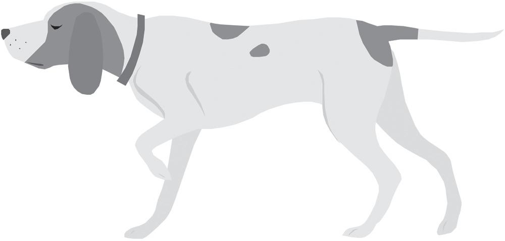
1-1. Diagram of a dog depicting the major directional anatomic terms, accepted by Nomina Anatomica Veterinaria.
VIEWING IMAGES
When radiographs were viewed as flm images, a method for consistently hanging flm on a viewbox was developed. Viewing radiographs in the same orientation for every subject reduces variation, and the brain becomes more familiar with the way a certain body part should appear. The basic aspects of that radiograph-hanging system are as follows:
n Lateral images of any body part should be oriented with the cranial or rostral aspect of the body heading to the examiner’s left (Figure 1-2).
n Ventrodorsal or dorsoventral images of the head, neck, or trunk should be oriented with the cranial or rostral aspect of the subject heading up and the left side of the subject positioned on the examiner’s right (Figure 1-3).
n As already noted, lateromedial or mediolateral images of extremities should be oriented with the proximal aspect of the limb at the top and the cranial or dorsal aspect of the limb heading to the examiner’s left (Figure 1-4). This orientation is correct regardless of whether the left or right limb has been imaged.
n Caudocranial (palmarodorsal or plantarodorsal) or craniocaudal (dorsopalmar or dorsoplantar) images of extremities should be oriented with the proximal aspect at
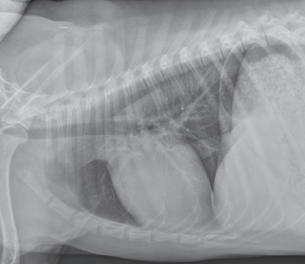
Correct orientation of a lateral view of any body part. A lateral view of the thorax is shown here.
1-3. Correct orientation of a ventrodorsal view of the head, spine, thorax, abdomen, or pelvis. A ventrodorsal view of the thorax is shown here. This same orientation would be used if the image were a dorsoventral view.
the top and the distal aspect at the bottom. These can all be considered sagittal-plane radiographs. There is no convention directing whether the medial or lateral side of the extremity should be on the examiner’s left (Figure 1-5). This orientation is correct regardless of whether the left or right limb has been imaged.
Cranial Caudal
Caudal Rostral
Dorsal
Figure
Dorsal
Cranial
Caudal
Ventral
Figure 1-2.
Cranial
Caudal
Left
Right
Figure
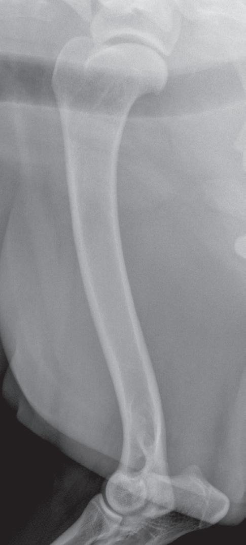
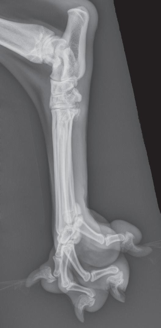
Figure 1-4. Correct orientation of lateral views of two extremities. A lateral view of a humerus (A) and a lateral view of a tarsus/pes (B) are shown here. Note the difference in directional terms depending on whether the part being imaged is above or below the tarsocrural or antebrachiocarpal joint.

Although these principles were developed to defne how a flm should be hung on a viewbox, they have carried over to digital imaging and are used to orient digital images correctly on a monitor or in print. The ability to adjust the orientation of the digital image on the monitor using the viewing software allows adherence to these principles regardless of the orientation of the original image. It is also important to realize that the position of the patient when the radiograph was made has no bearing on how the image should be oriented for viewing. This concept is commonly misunderstood. For example, it is a common misconception to think that ventrodorsal versus dorsoventral radiographs of the thorax would be oriented differently. This is not true.
STANDARD PROJECTIONS
Most standard radiographic examinations comprise at least two projections made at 90 degrees to each other. These are termed orthogonal views. Table 1-1 lists the most common orthogonal views for the major body parts. These views are named according to the point-of-entrance to point-of-exit of the primary x-ray beam.
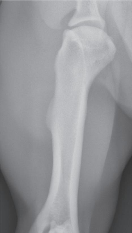
Figure 1-5. Correct orientation of a sagittal-plane radiograph of an extremity. A caudocranial view of a humerus is shown here. There is no convention regarding whether the lateral side of the limb is placed on the examiner’s right (A) or left (B). However, it is probably more common to orient medial and lateral relative to the patient. As such, a left limb would be oriented as in Figure 1-5A, and a right limb would be oriented as in Figure 1-5B.
Making the same standard orthogonal views of every body part is very important. Looking at the same radiographic projections and orientations repeatedly makes it easier to recognize abnormal from normal. On the other hand, when an object or body region is radiographed using an unconventional point-of-entrance to point-of-exit of the x-ray beam, the image becomes less recognizable and more diffcult to interpret (Figure 1-6).
Table 1-1 Common Orthogonal Views for Major Body Parts
Body Part View
Orthogonal View
Skull Left-right lateral or right-left lateral Ventrodorsal or dorsoventral
Spine Left-right lateral or right-left lateral Ventrodorsal*
Thorax Left-right lateral or right-left lateral Ventrodorsal or dorsoventral
Abdomen
Pelvis
Brachium, antebrachium, thigh, crus
Left-right lateral or right-left lateral Ventrodorsal*
Left-right lateral or right-left lateral Ventrodorsal*
Lateral-medial or medial-lateral Craniocaudal or caudocranial
Carpus/manus Lateral-medial or medial-lateral Dorsopalmar or palmarodorsal
Tarsus/pes Lateral-medial or medial-lateral Dorsoplantar or plantarodorsal
*Dorsoventral views of the spine, abdomen, or pelvis are rarely acquired.
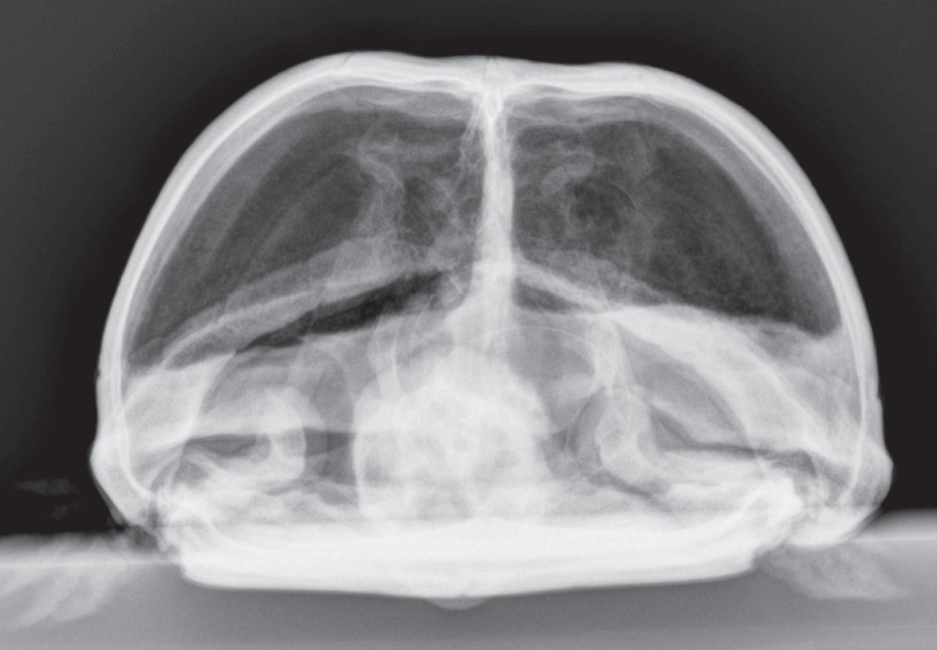
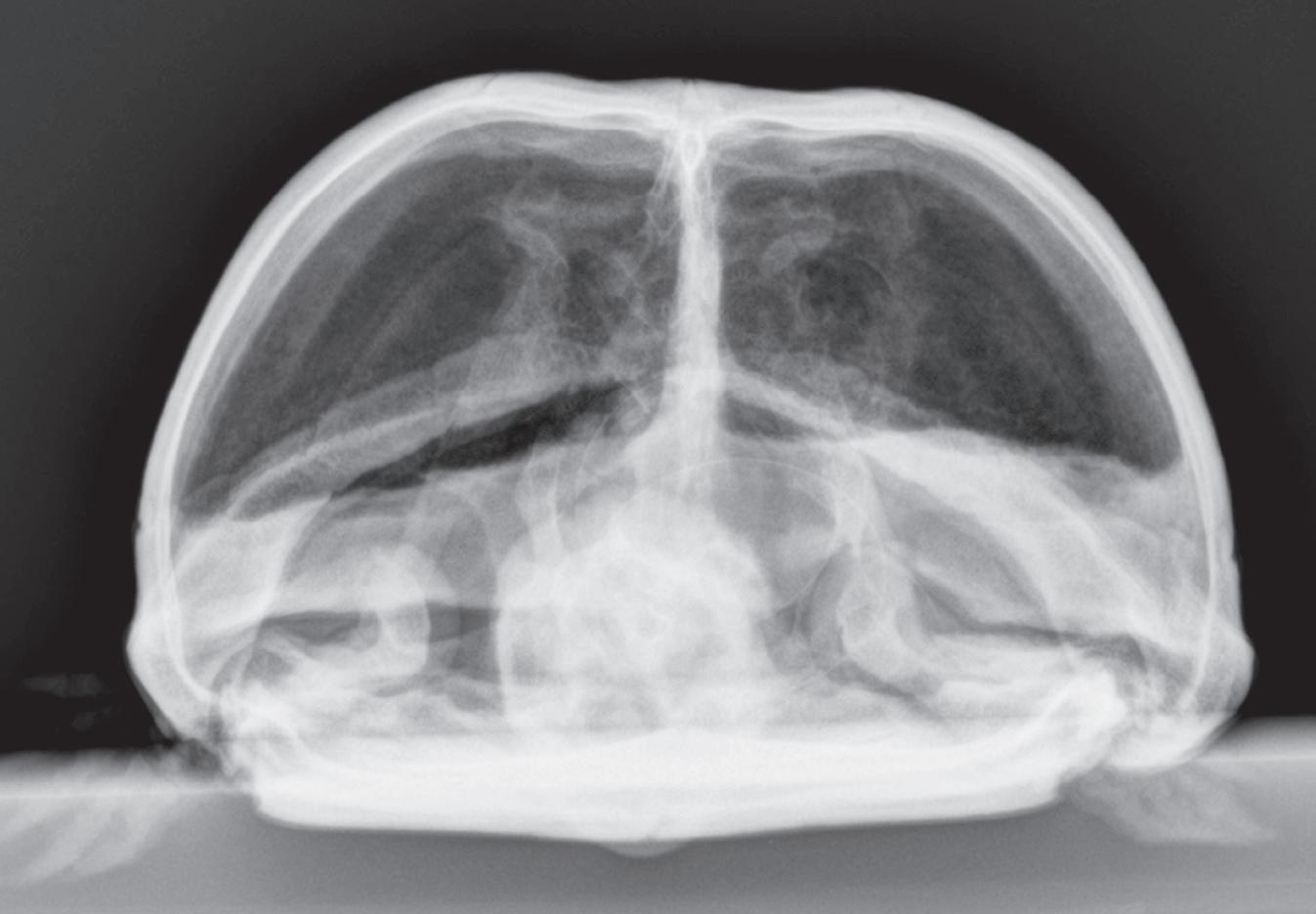
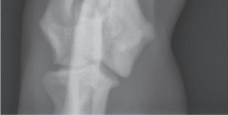
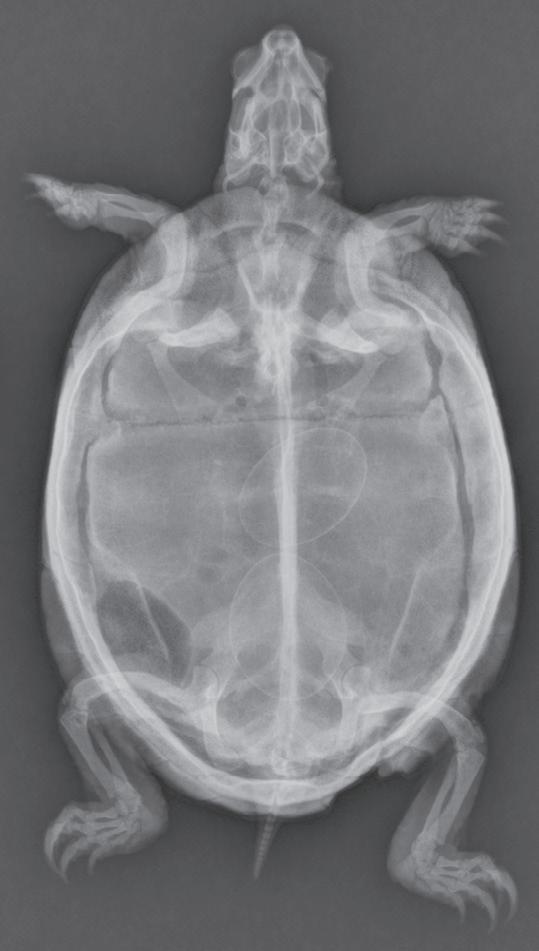
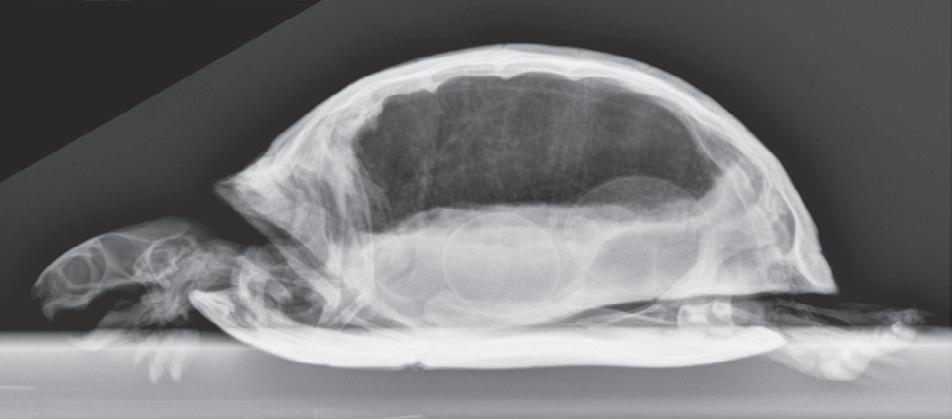
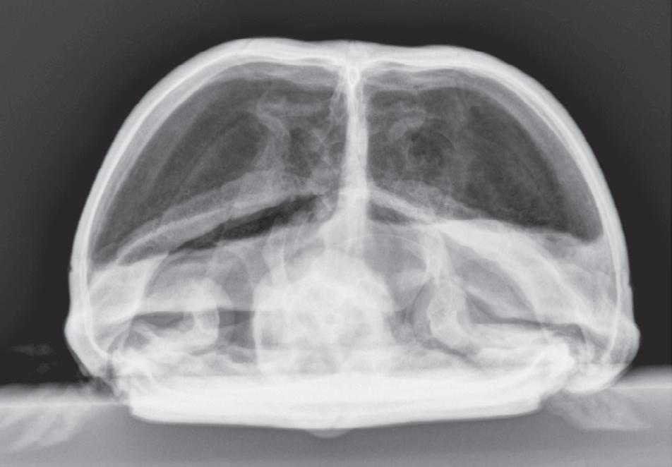
Figure 1-6. Dorsoventral (A), lateral (B), and rostrocaudal (C) radiographs of a box turtle. In A and B, which are orthogonal to each other, it is clear that the subject is a turtle. Eggs are visible in the coelom. In C, which is also an orthogonal view with respect to both A and B, it is not obvious that the subject is a turtle because this orientation is uncommon and unfamiliar. The eggs are also not visible in C.
OBLIQUE PROJECTIONS
For anatomically complex regions, such as the manus and pes, two orthogonal radiographic views are often not adequate because of the extensive superimposition, and important lesions can be missed. Other projections can be
used along with the two standard orthogonal projections to improve lesion detection. The objective of using multiple views is to project as many surfaces or edges as possible.
The best solution for accurate imaging of a complex structure is to use a tomographic imaging modality. As noted earlier, tomographic imaging modalities display images in slices, thus completely avoiding the problem of superimposition. Ultrasound, CT, and MR images are all tomographic. If tomographic imaging is not possible, the use of oblique radiographic projections can also reduce the complexity created by the superimposition of structures.
For oblique radiography, projections in addition to standard orthogonal projections are acquired. In other words, the entrance location of the primary x-ray beam is somewhere other than the locations used for standard orthogonal projections. Typically, this location is approximately midway between the entrance points for the conventional views, but other locations can also be used depending on the need. Understanding the point-ofentrance to point-of-exit radiographic naming method is crucial to understanding oblique radiographic images.
The following explanation of oblique radiography is based on the canine tarsus.* These principles also apply to other regions. If these principles are applied to the forelimb, plantar is replaced with palmar
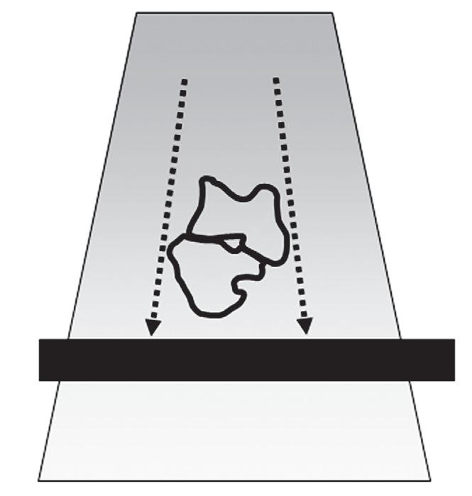
Dorsoplantar View
The dorsoplantar view is a standard radiographic view of the tarsus and pes (Table 1-2). In a dorsoplantar view of a tarsus/pes, the x-ray beam strikes the dorsal surface, and the image plate is plantar (Figure 1-7). In this view, the medial and lateral aspects are projected in an unobstructed manner (see Figures 1-7 and 1-8). This does not mean that only the medial and lateral edges can be evaluated because the infrastructure can still be assessed, but the lateral and medial edges are where a periosteal reaction or cortical erosion will be able to be identifed.
Lateral View
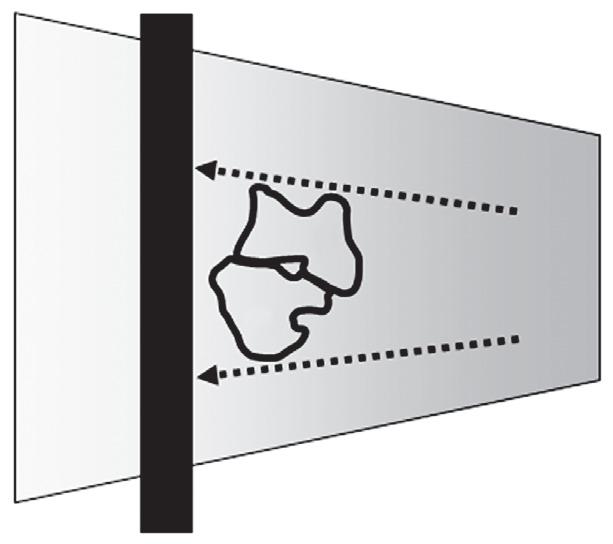
A lateral view is the orthogonal view to the dorsoplantar view and is made when the x-ray beam strikes the lateral or medial surface of a limb with the cassette or imaging plate on the opposite side (Figure 1-9). Although these views are called lateral views, lateral-medial or mediallateral is more correct depending on which side of the limb is struck by the primary x-ray beam.
In a medial-lateral view of a tarsus/pes, for example, the x-ray beam strikes the medial surface, and the image plate is on the lateral side (see Figure 1-10). In this view, the dorsal and palmar edges are projected in an unobstructed manner (see Figures 1-9 and 1-10). This does not
*The colorized surface renderings in Figures 1-8, 1-10, 1-12, and 1-14 were expertly prepared by Sarena Sunico, DVM, DACVR
Table 1-2 Correct Names for Radiographic Projections of a Limb Where the X-Ray Beam Strikes the Front Surface of the Limb and the Cassette or Imaging Plate Is Directly behind the Limb
Correct Name of View Orientation
Dorsopalmar Primary x-ray beam strikes front surface of forelimb at antebrachiocarpal joint or distal. Cassette or imaging plate is perpendicular to primary x-ray beam.
Dorsoplantar Primary x-ray beam strikes front surface of hindlimb at tarsocrural joint or distal. Cassette or imaging plate is perpendicular to primary x-ray beam.
Craniocaudal Primary x-ray beam strikes front surface of forelimb or hindlimb proximal to antebrachiocarpal joint or tarsocrural joint. Cassette or imaging plate is perpendicular to primary x-ray beam.
Figure 1-7. The object being radiographed depicts outlines of the talus (T) and calcaneus (C) obtained from a transverse CT image of a canine tarsus. The x-ray beam strikes the tarsus from the front. The correct name of this radiographic projection is a dorsal-plantar projection, and the only edges that will be projected without obstruction are the medial edge of the talus and the lateral edge of the calcaneus; dotted arrows indicate these edges. These are the only edges that can be evaluated for abnormalities such as periosteal reaction or cortical lysis. Other edges will be superimposed on another structure.

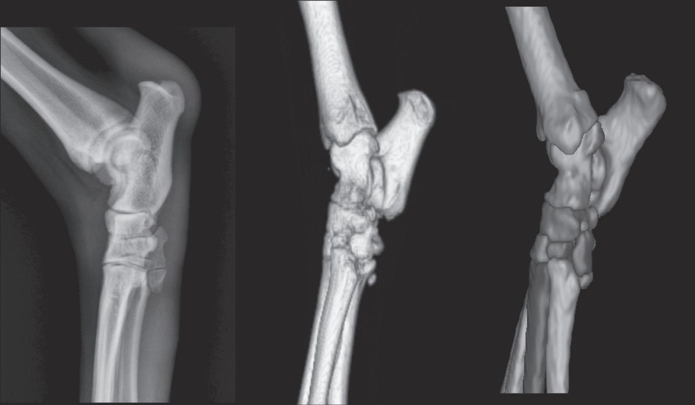
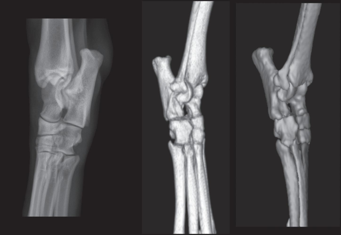
Figure 1-8. The left panel is a dorsoplantar radiograph of a canine tarsus. The middle panel is a three-dimensional rendering of a normal right canine tarsus from the perspective of the x-ray beam when making a dorsoplantar radiograph. The right panel is identical to the middle panel, except each bone has been colorized (see Color Plate 1). Colorizing makes it easier to comprehend the extent of overlap. Note in the radiograph that the only edges that can be evaluated are the medial and lateral edges.
Dorsal
Plantar
mean that only the lateral and medial edges can be evaluated because the infrastructure can still be assessed, but the dorsal and plantar edges are the only places where a surface change, such as a periosteal reaction or cortical erosion, will be able to be identifed.
Figure 1-9. The object being radiographed depicts outlines of the talus (T) and calcaneus (C) obtained from a transverse CT image of a canine tarsus. The x-ray beam strikes the tarsus from the medial side. The correct name of this projection is a mediallateral projection or abbreviated to lateral projection. In a lateral projection, the only edges that will be projected without obstruction from other edges are the dorsal edge of the talus (T) and the plantar edge of the calcaneus (C); dotted arrows indicate these edges. These are the only edges that can be evaluated for abnormalities such as periosteal reaction or cortical lysis. Other edges will be superimposed on another structure.
Oblique Views
In oblique views of the tarsus/pes, the entrance location of the primary x-ray beam is intentionally shifted to some point between dorsal and lateral or between dorsal and medial. Typically, this position is approximately midway between dorsal and lateral or midway between dorsal and medial, but other angles can be used depending on the circumstances (Table 1-3).
The oblique view where the entrance point is shifted 45 degrees between dorsal and medial is termed a dorsal 45-degree medial-plantarolateral oblique (D45°M-PtLO, often abbreviated to DM-PtLO) view (see Table 1-3). The x-ray beam strikes the dorsal surface midway between dorsal and medial with the image plate perpendicular to the primary x-ray beam (Figure 1-11). In this geometric arrangement, the dorsolateral and plantaromedial edges are visualized in an unobstructed manner (see Figures 1-11 and 1-12).
The oblique view where the entrance point is shifted 45 degrees between dorsal and lateral is termed a dorsal 45-degree lateral-plantaromedial oblique (D45°L-PtMO, often abbreviated to DL-PtMO) view (see Table 1-3 ). The x-ray beam strikes the dorsal surface midway between dorsal and lateral with the image plate perpendicular to the primary beam (Figure 1-13). In this geometric arrangement, the dorsomedial and plantarolateral edges are visualized in an unobstructed manner (see Figures 1-13 and 1-14).
It is important to reemphasize that the terminology used in this example of a pes applies to a pelvic limb; if
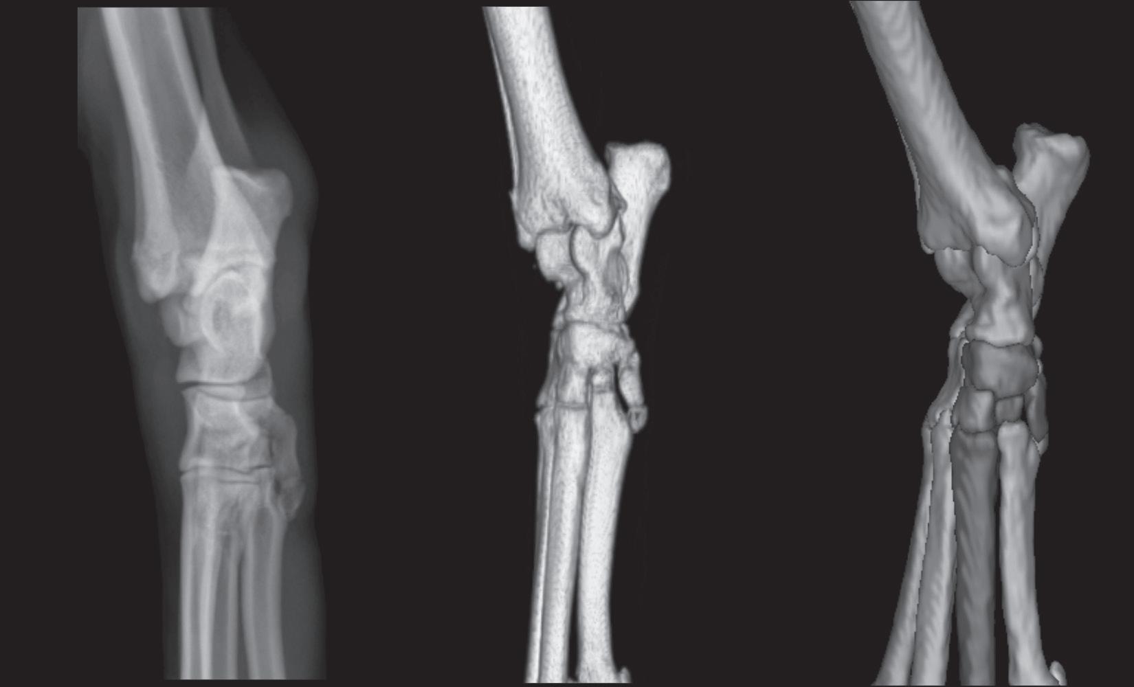
Figure 1-10. The left panel is a medial-lateral radiograph of a canine tarsus. The middle panel is a three-dimensional rendering of a normal right canine tarsus as seen from the perspective of the x-ray beam when making a medial-lateral radiograph. The right panel is identical to the middle panel, but where each bone has been colorized (see Color Plate 2). Colorizing makes it easier to comprehend the extent of overlap. Note in the radiograph that the only edges that can be evaluated are the dorsal and plantar edges. The proximal edge of the calcaneus is also visible in this projection because it is not superimposed on any other structure.
Dorsal
Plantar
Table 1-3 Correct Names for Oblique Radiographic Projections of a Limb Where the X-Ray Beam Strikes the Front Surface of the Limb Midway Between the Front and Side and the Cassette or Imaging Plate Is Behind the Limb and Perpendicular to the Primary X-Ray Beam
Correct name of View Orientation
Dorsal 45-degree lateral-palmaromedial
Dorsal 45-degree lateral-plantaromedial
Dorsal 45-degree medial-palmarolateral
Dorsal 45-degree medial-plantarolateral
Cranial 45-degree lateral-caudomedial
Cranial 45-degree medial-caudolateral
Primary x-ray beam strikes front surface of forelimb midway between dorsal and lateral aspects, at antebrachiocarpal joint or distal. Cassette or imaging plate is perpendicular to primary x-ray beam. Results in projection of dorsomedial and palmarolateral aspects of region of interest.
Primary x-ray beam strikes front surface of hindlimb midway between dorsal and lateral aspects, at tarsocrural joint or distal. Cassette or imaging plate is perpendicular to primary x-ray beam. Results in projection of dorsomedial and plantarolateral aspects of region of interest. (See Figures 1-13 and 1-14.)
Primary x-ray beam strikes front surface of forelimb midway between dorsal and medial aspects, at antebrachiocarpal joint or distal. Cassette or imaging plate is perpendicular to primary x-ray beam. Results in projection of dorsolateral and palmaromedial aspects of region of interest.
Primary x-ray beam strikes front surface of hindlimb midway between dorsal and medial aspects, at tarsocrural joint or distal. Cassette or imaging plate is perpendicular to primary x-ray beam. Results in projection of dorsolateral and plantaromedial aspects of region of interest. (See Figures 1-11 and 1-12.)
Primary x-ray beam strikes front surface of forelimb or hindlimb midway between cranial and lateral aspects, proximal to antebrachiocarpal or tarsocrural joint. Cassette or imaging plate is perpendicular to primary x-ray beam. Results in projection of craniomedial and caudolateral aspects of region of interest.
Primary x-ray beam strikes front surface of forelimb or hindlimb midway between cranial and medial aspects, proximal to antebrachiocarpal or tarsocrural joint. Cassette or imaging plate is perpendicular to primary x-ray beam. Results in projection of craniolateral and caudomedial aspects of region of interest.
a thoracic limb were being radiographed, plantar would be replaced by palmar
Not all oblique views involve the use of a primary xray beam angle between dorsal and lateral or dorsal and medial. For example, there are special oblique views of the bicipital groove of the humerus (cranioproximalcraniodistal fexed view of shoulder) and the proximal surface of the talus (dorsoplantar fexed tarsus) that are designed to make certain portions of these bones more conspicuous. Having a good understanding of how radiographs are named reduces confusion when assessing these more unconventional views and in understanding exactly why the images appear the way they do. These less frequently used oblique views are explained in more detail in the sections in which they are illustrated.
By using oblique radiographic views, more edges of a complex joint can be evaluated for periosteal reaction and cortical lysis, and small fragments can be localized accurately. It is important to understand the anatomy of oblique views to draw accurate conclusions regarding the location of any abnormality and to acquire the correct oblique view when interrogating specifc anatomic regions.

Figure 1-11. The object being radiographed depicts outlines of the talus (T) and calcaneus (C) obtained from a transverse CT image of a canine tarsus. The x-ray beam strikes the tarsus midway between the dorsal and medial surfaces. The correct name of this projection is a dorsal 45-degree medial-plantarolateral view. In this view, the dorsolateral edge of the talus (T) will be projected in an unobstructed fashion. The plantar edge of the calcaneus (C) will also be seen because it extends so far proximally; this is better comprehended in Figure 1-12. These are the only edges that can be evaluated for abnormalities such as periosteal reaction or cortical lysis. Other edges will be superimposed on another structure.
Dorsal
Lateral
Plantar
Figure 1-12. The left panel is a dorsal 45-degree medial-plantarolateral radiograph of a canine tarsus. The middle panel is a three-dimensional rendering of a normal right canine tarsus as seen from the perspective of the x-ray beam when making a dorsal 45-degree medialplantarolateral radiograph. The right panel is identical to the middle panel, but where each bone has been colorized (see Color Plate 3). Colorizing makes it easier to comprehend the extent of overlap. Note in the radiograph that the only edges that can be evaluated are the dorsolateral and plantaromedial edges. Even though the proximal aspect of the calcaneus is plantarolateral, it can still be seen in this view because it extends suffciently proximal that it will not be superimposed on the tibia.

Figure 1-13. The object being radiographed depicts outlines of the talus (T) and calcaneus (C) obtained from a transverse CT image of a canine tarsus. The x-ray beam strikes the tarsus approximately midway between the dorsal and lateral surfaces. The correct name of this view is a dorsal 45-degree lateral-plantaromedial view. In this view, the plantarolateral edge of the calcaneus (C) and the dorsomedial edge of the talus (T) will be projected tangentially. Dotted arrows indicate these edges. These are the only edges that can be evaluated for abnormalities such as periosteal reaction or cortical lysis. Other edges will be superimposed on another structure and cannot be assessed.
PHYSEAL CLOSURE
Juvenile orthopedic disorders are common, particularly in dogs. Many arise from disruption to normal physeal development. Breed, genetics, nutrition, intercurrent disease, activity, and trauma can all affect skeletal development adversely. Some understanding of the radiographic appearance of normal physeal maturation and the age at which this occurs is a prerequisite to the identifcation and management of such disorders. Table 1-4 provides an overview of when the various ossifcation centers appear, and Table 1-5 shows when physes are typically radiographically closed. It should be noted that there is considerable variation in physeal closure, and these tables are designed to act only as guides. The tables refect a compilation of data from multiple sources. Table 1-6 documents the approximate ages at which the fusion of skull bones occurs in both canines and felines. Figures 1-15 through 1-20 diagrammatically show the long canine bone and joint morphology from 1 month to 8.5 months. Figures 1-21 through 1-28 diagrammatically show the long feline bone and joint morphology from 3.5 weeks to 16.5 months.
Dorsal
Plantar
Figure 1-14. The left panel is a dorsal 45-degree lateral-plantaromedial radiograph of a canine tarsus. The middle panel is a three-dimensional rendering of a normal right canine tarsus as seen from the perspective of the x-ray beam when making a dorsal 45-degree lateralplantaromedial radiograph. The right panel is identical to the middle panel, but where each bone has been colorized (see Color Plate 4). Colorizing makes it easier to comprehend the extent of overlap. It is important to note that the dorsal surface of the radiograph is oriented to the viewer’s left; this is standard policy. The dorsal surfaces of the three-dimensional models are oriented to the viewer’s right because the models are anatomically correct, and this is the orientation that the radiographer would see. Note in the radiograph that the only edges of the tarsal bones where the surface can be evaluated are the dorsomedial and plantarolateral edges.
Table 1-4 Approximate Ages at Which Ossifcation Centers Appear (Canine and Feline)
Canine Feline
carpal (3 centers)
bone in abductor pollicis longus
METACARPUS/METATARSUS
Diaphysis of 1-5
of MC1
(FORE AND HIND)
Diaphysis of digits 1-5
STIFLE SESAMOID BONES
Table 1-4
TARSUS
SPINE
Atlas, three centers of ossifcation
Neural arch (bilateral)
Axis, seven centers of ossifcation Centrum of proatlas
Intercentrum 2
Centrum 2
Neural arch (bilateral)
Cervical, thoracic, lumbar, sacral vertebrae Paired neural arches and centrum
aEpiphyses are often absent in the last 1 to 2 caudal vertebrae.
Table 1-5 Approximate Age When Physeal/Ossifcation Center Closure Occurs (Canine and Feline)