


FEBRUARY 2023 • VOL. 13, NO.1 THE TECHNICIAN’S RESOURCE IA9OOWA ALIGNMENT WITHOUT LIMITS DIAGNOSTICS + DIGITAL INSPECTION + ALIGNMENT + ADAS CALIBRATION *Return on investment varies by service volume. CALCULATE YOUR REVENUE POTENTIAL RECOUP YOUR INVESTMENT IN AS LITTLE AS 30 DAYS At the Cost of a Typical Alignment System MAXIMIZE WITH A SINGLE SYSTEM & WORKFLOW PROFITABILITY & EFFICIENCY ADVERTISEMENT


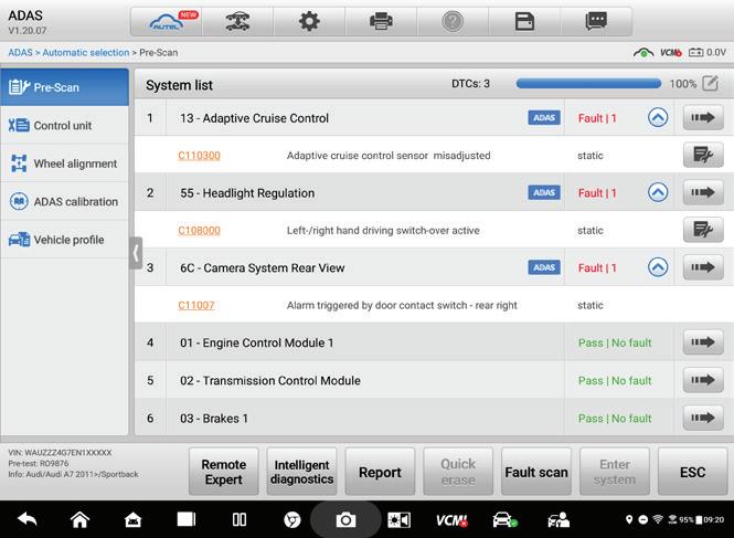

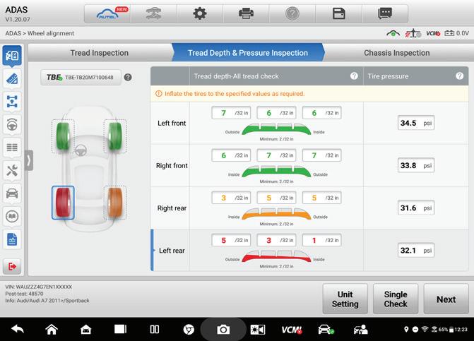
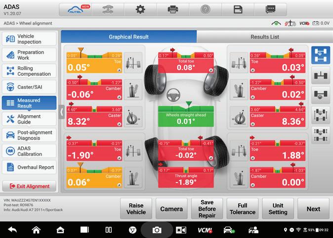

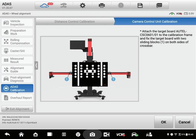
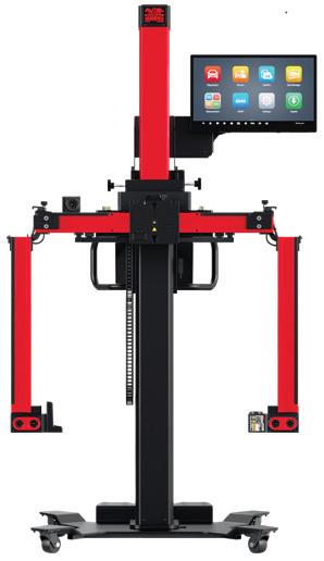
DIAGNOSTICS1 All Systems and Module Health Check Including Steering and Suspension. 2DIGITALINSPECTION Text or Email All Customized Reports Instantly to Your Customer. 3 ALIGNMENT 3D Wheel Alignment with Any Electronic Component Reset. 4 ADASCALIBRATION Step-by-Step Illustrated Instructions with Automatic Vehicle Height Tracking. WEB: AUTEL.COM | SUPPORT: 1.855.288.3587 EMAIL: USSUPPORT@AUTEL.COM FOLLOW US @AUTELTOOLS IA9OOWA At the Cost of a Typical Alignment System MAXIMIZE WITHASINGLESYSTEM&WORKFLOW PROFITABILITY &EFFICIENCY
THE TECHNICIAN’S RESOURCE


THE ABC S OF ABS


Wheel speed sensors aren’t just for braking anymore


THE HISTORY OF EV BATTERIES A DECADE OF FORD ECOBOOST LESSONS
TOOLS TO AVOID AN ENGINE TEAR DOWN

FEBRUARY 2023 • VOL. 13, NO. 1
| FEBRUARY 2021
Professionals Known for knowledgeable parts professionals who understand your business, Federated is dedicated to providing service professionals with quality brand name parts, business-building programs, and outstanding customer service to help you grow your business. www.federatedautoparts.com


TO Professionals Federated Auto Parts is known for experienced professionals who understand your business and are dedicated to providing unrivaled service to other professionals in the field. Come to Federated for the finest brand name, premium quantity auto parts available and our first-rate professionals. Come to Federated for the Best. www.federatedautoparts.com


FEBRUARY 2023 | ASP 3 departments STRAIGHT TALK Finding Future Employees There are bene ts to opening your doors to students TECH TIPS How to Compensate for a Torque Wrench Extension TECHNICAL SERVICE BULLETINS GMC, Mazda, Ram and more AD INDEX Technical UNDERSTANDING TODAY’S ABS Wheel speed sensors aren’t just for braking anymore THE FORD ECOBOOST The ins and outs of this engine platform EV BATTERY HISTORY The development of battery technology THE POWER OF ELECTRONIC PRESSURE TRANSDUCERS Avoid an engine tear down with this tool 04 08 32 34 09 13 20 23 COnTenTS FEB 2023 Vol. 13, No. 1 14 08 21 10 COVER PHOTO CREDIT: GETTY IMAGES
Finding Future Employees
There are benefits to opening your doors to students
FINDING QUALIFIED SHOP PERSONNEL can present a challenge, especially today. The unfortunate problem that many businesses face today has to do with fi nding people who want to work, and fi nding people who have a work ethic and are willing to roll up their sleeves and commit themselves to a job...any job.
While “stealing” technicians from other shops has been and always will be an option, consider forming an alliance with local trade schools. Offer your shop’s facility in the form of an “open house” event, inviting students to tour your shop, with your techs on site to provide a face-to-face with the students. Give the students a chance to see your operation and your shop’s daily routine. This gives them an opportunity to see how a shop runs its daily affairs in the “real world,” including shop maintenance, typical repair jobs, diagnostic work, etc. Your resident technicians can discuss, one-on-one, how the shop operates, how to deal with customers, and the range of duties and skills that are required. They can talk about everything from entry level to master tech positions, along with opportunities for advancement. This type of open-house event can take place after hours or on weekends when no customers are present, which allows you to invite groups of students.
In addition, separate programs consisting of small groups (perhaps three to five students) can take place on a workday, where students have an opportunity to see how service writers and technicians interact with customers. Keeping such groups small allows you to expose students to a typical workday to
observe, without getting in the way, much like medical residents in small groups are allowed to observe hospital practices.
By allowing students to closely interact with your shop’s technicians, your techs may be able to motivate them by describing exactly what they do and the satisfaction they get by seeing a job to completion. One-on-one casual conversations can work wonders for students who previously may have only attended classroom sessions and have never been exposed to “real world” scenarios.
Creating this type of program provides valuable insight for trade school students who are considering the automotive repair field as a profession, and it gives you the chance to meet (and evaluate) potential shop employees. At worst, you may gain absolutely nothing for your efforts. At best, you may encounter a few select people who appear to have a sense of purpose and potential and deserve consideration for future employment.
MIKE MAVRIGIAN EDITOR


4 ASP | FEBRUARY 2023
STRAIGHT TALK
INCREASE YOUR PROFITABLE
POWERFUL HARDWARE + EXPANDED SOFTWARE AT THE CORE!
MS906PRO
MS906PRO-TS EXCLUSIVE SOFTWARE
• Enhanced TPMS Status Screen


• Four 1-Sensor Programming Options
• Activate, Read & Relearn All Sensor Brands

• Batch Programming up to 20 1-Sensors
NEW SOFTWARE FEATURES
• ADAS Calibration Capability*

• Battery Analyzation Capability*
• Scan VIN: Text/Barcode Recognition with Camera
• Camera-Based License Plate Scan Recognition
• Advanced ECU Coding & Adaptions
• Customer Diagnostic Reports / Print & Save Easily
*Additional Purchase Required
V200
No CAN FD Adapter Needed
UPGRADED HARDWARE
• 8” Touchscreen / Includes VCI200

• Octa-Core Processor / 128G Memory / 4G RAM
• 5MP Front & 16MP Rear Camera
CLOUD ACCESS!
• Pre/Post Scan Reports
• Customer Vehicle Data
WEB: AUTEL.COM | SUPPORT: 1.855.288.3587 EMAIL: USSUPPORT@AUTEL.COM FOLLOW US @AUTELTOOLS
OnlIne
3515 Massillon Rd., Suite 200, Uniontown, OH 44685 (330) 899-2200, fax (330) 899-2209
Website: autoserviceprofessional.com

PUBLISHER
Greg Smith / gsmith@endeavorb2b.com (330) 899-2200, Ext. 2212
EDITORIAL
Editor: Mike Mavrigian mmavrigian@endeavorb2b.com
Managing Editor: Joy Kopcha jkopcha@endeavorb2b.com
Associate Editor: Madison Gehring mgehring@endeavorb2b.com
PRODUCTION
Senior Art Director: Jonathan Ricketts
Art Director: Molly VanBrocklin
Production Manager: Karen Runion krunion@endeavorb2b.com
CONTRIBUTORS


Je Taylor, Diagnostics & Drivability Specialist
Bill Fulton, ASE Master Tech
Craig Van Batenburg, EV Technology
ADVISORY BOARD
Chris Chesney, Repairify
Jake Sorensen, McNeil’s Auto Care
Seth Thorson, Eurotech Automotive


Donny Seyfer, Seyfer Automotive
ASP’S WEBSITE IS THE GO-TO SITE FOR VEHICLE INFORMATION 24/7.

Turn to it any time you need the latest technical service bulletins, in-depth technical articles and the newest products. Our site also features news from suppliers and manufacturers to keep you up-to-date on what’s happening in the automotive industry.


Plus, go to our website to renew your subscription to ASP, read the digital version of each issue and sign up for a free subscription to our weekly eNewsletters!
Bill Fulton, ASE Master Tech
MARKETING STRATEGISTS
Dan Thornton / dthornton@endeavorb2b.com (734) 676-9135, mobile (734) 626-4950
Bob Marinez / rmarinez@endeavorb2b.com (330) 899-2200, ext. 2217
Marianne Dyal / mdyal@endeavorb2b.com (706) 344-1388
Sean Thornton / sthornton@endeavorb2b.com (269) 499-0257
Kyle Shaw / kshaw@endeavorb2b.com (651) 846-9490
Martha Severson / mseverson@endeavorb2b.com (651) 846-9452
Chad Hjellming / chjellming@endeavorb2b.com (651) 846-9463
EXECUTIVE OFFICER
Vice President: Chris Messer
6 ASP | FEBRUARY 2023
TECHNICIAN’S RESOURCE
THE
VISIT AUTOSERVICEPROFESSIONAL.COM TODAY


ALL THE TOOLS YOU NEED IN ONE PLACE! Call Now for a FREE catalog! WORK MEETS COMFORT ROLLING CREEPER SEAT CONVERTS FROM HIGH TO LOW LOCKING HEIGHTS UP TO 6 The ergochairTM is the adjustable height rolling work seat which will make performing awkward work tasks ergonomically easier and safer. This comfortable creeper seat offers a full range of mobility, increased productivity, and reduced fatigue. To Learn more visit www.bendpak.com/ergochair 1-800-253-2363 • WWW.BENDPAK.COM ©2023 BendPak Inc. All rights reserved. ty, sit Shop Equipment | Automotive Tools | Car Lifts | Wheel Service & More or visit www.wrenchers.com 1-800-261-7729 Ask about our price promise guarantee. 1-800-261-7729 www.wrenchers.com © 2023 Wrenchers LLC. All Rights Reserved. NEW
TECH TIPS
TORQUE WRENCH EXTENSION
In certain situations, primarily due to access challenges, you may not be able to use your torque wrench when fitted with a socket wrench. In torquecritical applications such as cylinder heads or intake manifolds, you may run into cases where you simply cannot engage a fastener head using a conventional socket. In those situations, you can use a torque wrench extension that features a box-wrench.
By “extension,” we are not referring to a deepwell socket or socket extension that is in line with the torque wrench head. Instead, we’re referring to an offset extension that engages to the torque wrench drive, but effectively increases the length of the torque wrench. It features an open crows-foot or box wrench at the opposite end, and allows access perpendicular to the fastener. While such an extension allows easy access to the fastener, you need to understand that the torque wrench value setting must be adjusted in order to compensate for the increased leverage effect, since adding the wrench extension makes the tool longer. Because of this, if you set the wrench to the spec value, the added tool length will result in a slight over-tightening, beyond the torque wrench setting.
If you want to know where to set the torque wrench when using an adapter that alters the effective length of the wrench, you must calculate to compensate for the adapter. If the distance from the wrench drive to the center of the bolt makes the wrench longer, the final wrench setting must be adjusted to a lower value in order to compensate.
If the distance from the wrench drive to the bolt center makes the wrench shorter, the wrench must be set to a higher value.

The following is a method to make the calculation when the adapter makes the wrench longer:

E…………….Effective length of the extension (for example, using a 2-inch-ling extension)
L…………….Lever length of the torque wrench (from center of the wrench drive to the center of the adapter’s grip area)
TW…………Torque setting on the torque wrench
TE…………..Torque applied by the extension to the fastener
FORMULA: TW = L/L+E x TE
Let’s say that you want to torque a bolt to 30 ft-lbs., but you’re using a wrench extension. For this example, the length of the torque wrench is 12 inches from center of the handle to center of the drive. Let’s also say that the extension is aiming away from the wrench drive, making the distance from the center of the wrench drive to the center of the bolt 2 inches. This makes the torque wrench 2 inches longer. In this case, you would divide the length of the torque wrench (L…from the center of the handle to the center of the drive) by L+E, then multiply that ratio by the desired value.
In this example, where the torque wrench is 14 inches long and the extension is 2 inches long and we want to obtain 30ft-lb of torque value, the formula would be as follows:
(L) 14 divided by (L+E) 14+2 multiplied by (TE) 30 14 divided by 16 = 0.875
0.875 multiplied by (TE) 30 = 26.25. The new torque wrench setting should be 26.25 ft-lb.

8 ASP | FEBRUARY 2023
Above: Example of a torque wrench extension. This example is 2-inches long. (images courtesy Mike Mavrigian)
Above: Example of the need for an extension due to limited bolt access.
Left: When measuring the length of the torque wrench, measure from the center of the drive head (see left) to the approximate center of the grip. In this example, the length is 14.5 inches.
Understanding Today’s ABS
Wheel speed sensors aren’t just for braking anymore
BY JEFF TAYLOR
THE ANTI-LOCK BRAKING SYSTEM (ABS) is certainly not a new feature on the modern vehicle. The development of the ABS has continued and is now heavily integrated into vehicle operation.
If we look at the 2021 Ford F150 V6 2.7L, there are as many as 16 systems/subsystems (depending on the vehicle options) that are considered part of the ABS. There is the ABS, auto hold, drive away brake release, electronic brake force distribution, electric parking brake control, electronic stability control, emergency brake assist, hill descent control, hill start assist, roll stability control, selectable drive modes, adaptive cruise control, collision avoidance, traction control, trailer sway control and torque vectoring control.
The handling and control of the vehicle is now deeply combined with the ABS system, and all these subsystems are using wheel speed sensor (WSS) data gathered by the ABS system to make critical vehicle control system decisions. (Note: The WSS is often referred to as the ABS sensor, but for this article I will refer to it as the WSS.)
Early ABS only needed to know the speed of the wheels on the vehicle to make its decisions. These first systems only wanted to prevent wheel lockup during braking. The passive WSS supplied that data to the ABS control module. The passive WSS is a two-wire, analog, variable reluctance (VR), AC-generating sensor. The passive WSS sensor was mounted near a rotating reluctor ring (axle tone ring) and generated an AC voltage signal that was interpreted by the ABS module as a wheel speed. The passive WSS produces a signal output that will increase in both frequency and amplitude as
the reluctor speed increases. The passive WSS is robust, cheap to produce and uses proven technology, but the passive WSS has three significant limitations. Passive WSS sensors are not capable of detecting the wheel’s direction. They lack the ability to accurately detect low wheel speeds (typically below 3 mph) and are very sensitive to air gap for proper operation.
Today’s complex braking systems and the various subsystems involved require more accurate wheel speed data. The ABS needs to know, very precisely, the wheel’s speed, down to zero (not moving) and it also needs to know the direction the wheel is rotating (forward or backward).
There have been two active WSS designs used so far: the three-wire, Hall-effect, and the magneto resistive sensor, in two distinct variations.
The Hall-effect sensor active WSS design is easily identified by its distinct three-wire hookup (power, ground and output) and could detect lower wheel speeds. If the reluctor was shaped properly it could even detect wheel rotation. But the Hall-effect WSS was sensitive to temperature and the harsh brake environment, so it was used in very limited circumstances.
The magneto resistive sensor active WWS design detects the changes in magnetic flux and is the preferred design. Each of the magneto resistive sensors will have a small integrated circuit (module) built into the body of the sensor. This module will output the WSS data (wheel speed and rotational direction) in a digital, square wave output. The active WSS is small, light, handles vibration and temperature fluctuations, isn’t sensitive to changes in air gap (they can tolerate a wide air gap) and is tolerant of electromagnetic interference.
FEBRUARY 2023 | ASP 9
UNDERSTANDING TODAY’S ABS
The first design of active WSS magneto-resistive sensor uses a toothed tone ring like the passive WSS uses. The sensor body will have a magnet that is wrapped with a coil of wire forming a sensing circuit. An integrated circuit in the sensor will try to maintain a constant current in the sensing circuit, using voltage fed from the ABS control module. As the wheel rotates, moving the tone ring past the magnet in the sensor, the changes in the magnet flux will change the circuit’s resistance, and this change in resistance will change the current flow through the circuit. The sensor’s integrated circuit will interpret these changes in resistance as a high and low signal and process the information, so it can send both a high and low digital signal to the ABS module. The ABS module will look at the frequency of this output and then calculate the wheel speed.
The second design of active WSS (the one most used today) still relies on detecting the changes of a magnetic flux, but in this design the magnet is moving. There will not be a toothed tone ring on this type of active WSS.
The wheel hub or bearing assembly will have a unique magnetic encoded reluctor, often incorporated into the outer rubber seal of the wheel bearing. This encoded reluctor is made of a special ring of carefully arranged magnets in alternating north/south pole position, embedded in the rubber seal, which will move past the active WSS.

As the wheel turns, the active WSS will be subjected to the alternating north/south magnets and interpret these magnetic flux changes. Inside the active WSS there are two sensing elements that are mounted side-
by-side and the needed integrated electronics, fed power from the ABS module. Each of the sensing elements will detect the presence of the magnetic field from the magnets mounted in the reluctor and will convert this magnetic field detection to a digital high and low signal output. This style of active WSS is often referred to as the dual-element active wheel speed sensor.
The frequency of the high and low switching will be interpreted as wheel speed, and the sensing elements are always providing signals so a stationary or stopped wheel is easily detected.

Since the sensing elements are mounted side-byside, in the sensor tip, the two voltage signals they generate will always be slightly out of phase. As one sensor signal rises or falls, it will be just a few degrees after the other sensor. This is how this type of active ABS WSS can detect the direction of a wheel’s rotation.
Before we start a diagnostic on an ABS WSS issue or failure, we need to establish what type of WSS we are dealing with. A common mistake when diagnosing an ABS WSS issue is the assumption that all two-wire sensors are going to be the same. But remember there are passive and active ABS WSS and most of them will have two wires. The dual-element active WSS will lack a toothed tone ring so it’s straight forward to identify.
10 ASP | FEBRUARY 2023
The ABS system is heavily integrated into today’s vehicles. This bulb check shows three system warning lights that are dependent on wheel speed information for proper function.
UNDERSTANDING TODAY’S ABS
Don’t overlook the value of a visual inspection when performing any diagnostic. This ABS light was on with a code for missing wheel speed sensor data. The sensor was falling off.
Wiring diagrams and service information will typically not tell the technician the type of WSS they are diagnosing. The best way to decide if you are unsure about the sensor type is to measure the voltage at the ABS WSS connector. The active sensors will have a voltage of 5V to 12V being supplied to the sensor from the ABS controller. Be careful when testing for this voltage, as some vehicles (Honda/Acura) will quickly detect an opening in the circuit if the WSS is unplugged and stop supplying that voltage until the ignition is cycled. If the testing reveals a voltage signal, we are dealing with an active type WSS.
It is important to remember that we cannot check the resistance of an active type WSS sensor, like we did with a passive WSS. The active type of WSS requires a tiny current supplied by the ABS control module through a resistor (in the ABS module) for operation. Testing the resistance of an active WSS could possibly result in wrong or confusing readings and even possible damage to the sensor itself.

Now that we have identified the type of WSS sensor that we are diagnosing, there are several ways we can diagnose the sensor’s output. Before any diagnostics take place, ensure the ignition is switched “ON” as an active WSS needs power from the ABS module. The use of a scan tool is going to be necessary and is the usual starting point for almost all diagnostics today. We can look for and retrieve any diagnostic trouble codes that may aid our diagnostics. Always perform a full system, full module scan, because these systems are so integrated, the codes or data you are looking for may not be under the ABS section. The scanner will also provide the needed live data that will aid in diagnostics.

We can use the scan tool and watch the wheel’s speed data, but the data on the scan tool may be buffered and hide the issue, especially if the issue is intermittent. The active WSS will output a digital square wave when the wheel is rotated. This signal can be detected and analyzed using a scope (the preferred method), micro current amp clamp or DVOM. When evaluating the output of an active WSS, only the frequency of the signal output (when displayed on the scope) will change when the wheel is turned.
The square wave output displayed on the scope will be approximately 0.6V. You can also assess the output using a DVOM and watch for the 0.6V voltage change or use a micro-amp clamp and watch for a 14mA to 7mA

FEBRUARY 2023 | ASP 11
Using an oscilloscope is the best method to diagnose an issue on any wheel speed sensor, either active or passive, especially if the reluctor or encoder is hidden from view.
The active wheel speed sensor is easily visible in this photo, taken during a wheel bearing replacement.
This scope pattern shows the pattern that a dual-element active WSS will generate when the wheel is turned by hand.
change either on the scope or on the DVOM display, as the wheel is turned. Using a scope will be the best bet for proper active WSS operation verification. It will quickly show the sensor output. If the active WSS is using a tone ring it will expose physical issues such as blocked, rust-filled or damaged teeth or cracks. If the active WSS is using the dual element type sensor it will show missing or damaged magnetic reluctor sections, and this is very helpful when the reluctor is not visible.
Today’s vehicle systems are heavily integrated, and the ABS is a perfect example. But the proper functioning of the braking system and all the other systems involved are relying on correct WSS speed and wheel direction information. Proper diagnostics of a WSS issue will rely on the ability to recognize what type of sensor we are diagnosing and how it functions.
And when diagnosing an ABS WSS issue, don’t underestimate the power of the visual inspection. When diagnosing an active WSS concern on many GM vehicles (other manufacturers have the same issue), the bonded magnetic encoder reluctor on the wheel bearing seal will degrade, separate, split and fall off. This can set several DTCs and illuminate warning lights.


A visual inspection will typically find this issue long before a scope or other test equipment other than the scan tool, is ever involved.
Jeff Taylor boasts a 30-plus-year career in the automotive industry as a fully licensed professional lead technician. Jeff works for the CARS Training Network Inc. in Oshawa, Ontario, Canada. He is also heavily involved in government focus groups, serves as an accomplished technical writer, and he has competed in international diagnostic competitions as well as providing his expertise as an automotive technical instructor for a major aftermarket parts retailer.
12 ASP | FEBRUARY 2023
This rear hub assembly from a Ford shows the magnetic encoder that is attached to the hub assembly. The encoder magnets are clearly visible and coated with metallic debris from the brakes.
UNDERSTANDING TODAY’S ABS
This front hub from a 2015 Impala shows how the magnetic encoder ring has separated and fallen, causing several warning lights to illuminate and codes to set in many modules.
The Ford EcoBoost
The ins and outs of this engine platform
BY JEFF TAYLOR
FORD’S ECOBOOST FAMILY OF engines has been around for more than a decade. The automaker has been installing EcoBoost engines in various makes and models since 2010.
When Ford engineers were tasked with developing a new engine family, they had several goals. It had to be more fuel efficient and produce fewer emissions, but this new engine family’s design also had to supply the same power and torque as its predecessors, which were larger displacement, naturally aspirated, engine designs.
The design of the EcoBoost engine family does just that. It supplies the power, torque, emission gains and good fuel economy that Ford wanted from a smaller, lighter, cost-effective engine family.
To achieve these engine design goals, the smaller displacement EcoBoost engines would incorporate three common traits: turbocharging (single or dual), direct injection (GDI Gasoline Direct Injection, or as Ford calls it, GTDI Gasoline Turbo Direct Injection), and the use of variable camshaft timing.
The EcoBoost engine family is popular and used in many of Ford’s vehicles, and as vehicles age, these engines are needing service. EcoBoost engines offer several challenges that technicians need to be aware of when it comes to servicing.
The first is timing belt service. There are certain EcoBoost engines that are equipped with a timing belt, and it will need to be serviced at a prescribed interval. The recommended interval is at the 150,000mile mark on the 1.0L, 1.5L and 1.6L engines. There is a difference in the timing belt configurations on these engines. The 1.5L and 1.6L EcoBoost engines are what most of us would consider a normal timing belt: complicated to service, but kept clean and dry from exposure to engine oil. The 1.0L EcoBoost engine is a different beast and uses a wet belt design. This means that the timing belt is exposed to the engine’s oil. This timing Belt-In-Oil (BIO) installation goes against all the norms that we as techs have been accustomed to. There have been issues with the BIO on the 1.0L engines. The belt starts to fail, and the resulting debris can clog the oil pump that is also driven using a small BIO belt. This can result in loss of oil pressure and severe engine damage. (Note: the 2018 redesigned 1.5L 3-cylinder EcoBoost engine is now equipped with a timing chain.)
Mounting the timing belt inside the engine and exposing it to the engine’s oil is done for varied reasons. But the most significant reason is that a timing belt that is running in oil will have 30% lower frictional losses than a typical dry timing belt or fully lubricated timing chain assembly that is performing the
FEBRUARY 2023 | ASP 13
THE FORD ECOBOOST
same function. This reduction in friction increases the engine’s fuel economy and reduces the engine’s emissions. But there are other reasons that Ford is running the timing belt on the 1.0L in engine oil — it allows for a more compact engine design, and it lowers the engine’s noise, vibration and harshness (NVH) and it is significantly quieter when in operation. NVH is something that manufacturers spend many hours trying to eliminate.


Running the timing belt in oil exposes the belt to all the impurities that will be circulating in the engine oil, and this highlights the need for ensuring that the proper manufacturer prescribed engine oil is used when performing oil change services.


The timing belt will now be subjected to the soot, debris, engine wear particles, acids, moisture and all the other engine oil impurities while in operation. These impurities can accelerate BIO wear and cause delamination, separation and other wearrelated failures. The materials that the BIO are manufactured from are designed to resist wear and provide long lasting durability when the proper recommended engine oil is used.


If the wrong oil is used or an incorrect maintenance schedule is followed, timing belt issues and even failure can become a reality.


14 ASP | FEBRUARY 2023 THE FORD ECOBOOST
A COMPLETE LINE OF masterpro® finishing pads Get the right finishing pads for every step of the refinishing process. AVAILABLE EXCLUSIVELY AT 2302ASP_OReillyAutoParts_3rdV.indd 1 1/18/23 1:37 PM
This 2015 Ford Escape 1.5L EcoBoost engine was getting a replacement timing belt. Shown here is one of the special tools needed to set the camshafts in position for service. (all photos courtesy of the author)
INSTALL PREMIUM FROM BRAKEBEST® SELECT


BRAKE PADS & ROTORS


PREMIUM BRAKE PADS
• OE performance for all driving conditions
• OE-style friction material formulations


• Integrally molded for increased durability
• Slotted and chamfered noise-reducing design


• Stainless steel hardware included on select applications
PAINTED HAT ROTORS
• Covers 2004 and newer models
• 1000+ painted part numbers
• Corrosion protection on the hat, edges, and vanes
MAKING IT FASTER AND EASIER THAN EVER TO ORDER PARTS

PREMIUM BRAKE PADS
• 5-layer shim with dual-steel layers optimize noise-canceling performance
• OE-specific friction formulations; ECE R90 certified friction on European applications (on applications where available)
• OE-style chamfers and slots help dissipate heat and minimize noise
• Break-in coating promotes a quicker, more effective break-in
ADV 1802 FIRSTCALLONLINE.COM Visit our website for a complete, internet-based catalog designed exclusively for the Professional.
EXCLUSIVELY AT Let Us Be Your Parts & Equipment Supplier
AVAILABLE
PROGRAMS & BRANDS Scan here with your phone’s camera to view the catalog! WWW.FIRSTCALLONLINECATALOGS.COM
The changing of the timing belt on the 1.0L, 1.5L and 1.6L engines requires special tools and procedures that need to be followed carefully to ensure correct base engine mechanical timing.
Engine oil and oil filters is another vital service to the EcoBoost engine. Ford uses an IOLM (Intelligent Oil-Life Monitor), and the Ford scheduled maintenance does call for extended oil change intervals. These intervals can stretch to as far as 10,000 miles or a full year. Of course, many techs, customers and shop owners do not think favorably about the use of extended length oil service intervals.
But Ford is confident that under normal driving conditions, when the proper manufacturer’s recommended engine oil is installed and maintained at the correct level, the length of time between oil changes calculated by the IOLM is acceptable.
Many technicians take issue with extended oil change intervals because they feel that the average vehicle is not exposed to the “normal driving parameters” described in the owner’s manual and assume there should be more frequent service because of this.

But when we look closely at the factory scheduled maintenance, even when a vehicle is used for towing, experiences extended idling, or operates for long distances at low-speed city driving (taxi operation), the IOLM is to be followed. The only exception is when the vehicle is used on sandy or unpaved roads. The IOLM will adjust the length of time and mileage between oil change services based on the vehicle’s operating conditions.
The algorithms that Ford’s IOLM uses will take into consideration the types and duration of driving, then process this information with many other pieces of data (ambient and engine temperatures, for example) and then adjust the length of the oil change interval. Ford is quick to point out that “conditions that could accelerate an oil change interval include towing, short-distance driving, and driving in extreme temperatures,” and that an oil change and other maintenance items may need to be performed at a quicker interval.
The service interval can be as low as 3,000 miles or go to the extended distance of 10,000 miles. But the IOLM is depending on the customer to keep the correct amount of engine oil in the engine. This is a critical and most often overlooked condition.

16 ASP | FEBRUARY 2023 THE FORD ECOBOOST
This photo shows the oil filter housing drain that drains the oil filter housing into the block and the “O-rings” that need to be changed when servicing the oil filter on the 2.7L EcoBoost engine.
Here’s a look at the tools needed to perform the timing belt replacement on the EcoBoost 1.5L or 1.6L 4-cylinder engines.
There are three important notes in the owner’s manual when it comes to maintaining the engine oil level:
1. Severe driving conditions such as extended high engine speeds, high engine loads, engine braking or hard cornering maneuvers can cause higher oil consumption (approximately one quart per 500 miles). As a result of these driving conditions, you need to check the engine oil level at every refueling and adjust to maintain proper levels to avoid engine damage.
2. Check the engine oil level every month.
3. Never exceed one year or 10,000 miles between oil change intervals.

The EcoBoost engine family has two specific manufacturer oil specifications. SAE 5W-30 Premium Synthetic Blend WSS- M2C946-B1 for the 2.0 L, 2.3L, 2.7L and 3.5L and SAE 5W-20 Premium Synthetic Blend WSS-M2C945-B1 for the 1.0L and 1.5L. (Be sure to check your information system or the vehicle owner’s manual for the proper engine oil specifications.) This oil formulation meets the needs of the EcoBoost engine’s turbocharger assembly and allows for the IOLM to properly calculate the life left in the engine’s oil.
There is another important note that needs to be shared when servicing and changing the oil filter on the 2.7L V6 Ford EcoBoost engine. The oil filter housing needs to be loosened and removed before draining the engine oil. The cartridge oil filter of the 2.7L V6 has a filter housing drain (the extended part of the oil filter housing assembly) that will allow the housing oil to drain into the oil pan before the drain plug is removed. It’s also important to carefully replace the three “O-rings” that are on the oil filter housing when performing an oil change service on these engines.
Intake valve deposits are a common issue that most GDI engines will suffer from at some point in their operation, and the EcoBoost engine is not immune. The lack of proper and periodic maintenance is a major factor, as are PCV design, poor fuel quality, and the valve overlap created by the variable valve timing operation. Intake valve deposit formation has also been closely linked to the use of incorrect engine oil, yet another reason for using the proper specified engine oil.
The EcoBoost engine family has been susceptible to significant issues with intake valve deposits, and in

FEBRUARY 2023 | ASP 17
Here’s a look at both the GDI and PFI injector locations on this cutaway 3.5L V6 EcoBoost engine.
A view of the intake valves on a 2016 3.5L V6 EcoBoost engine showing the buildup of carbon. Although not extreme, it was causing issues when cold.
extreme cases it will affect engine operation and need to be removed. The cleaning of these deposits from the intake valves on the EcoBoost engine has been an area of concern among technicians. The technician’s fear relates to damaging the turbocharger.

When these intake deposits are removed during a cleaning procedure, great care must be taken to ensure that nothing is ingested into the engine. It could be expelled onto the turbine of the turbocharger, causing turbocharger issues.
The hard carbon deposits that could be softened using a spray cleaner or other induction cleaning device could make their way to the turbine of the turbocharger, and if they become lodged or attached, they can damage the turbocharger itself.
Ford does not recommend or endorse any induction flushing methods to remove the accumulated carbon on the intake valves of the EcoBoost
engine, nor does it recommend any engine oil additives or flushes.
But that doesn’t mean that EcoBoost intake valve deposits aren’t an issue. The newer Ford EcoBoost engines are now equipped with dual injector systems, using both Port fuel injection (PFI) and GDI injectors. This setup addresses intake valve deposit formation while optimizing the benefits of both fuel injection systems.
PFI is cheaper to produce, cools the incoming air, produces lower particulate matter emissions, and cleans the backs of the intake valves, reducing deposits. However, PFI may allow fuel to condense in the intake ports and cylinders, skewing fuel trims and air fuel ratios. GDI reduces the chances of ping or detonation, allows for high compression ratios, lowers combustion chamber temperatures, and allows for higher turbocharger boost pressures. But GDI is more expensive to produce, has higher engine parasitic power losses (high-pressure fuel pump), intake valve carbon formation issues and higher particulate matter emissions.
Using a combination of PFI and GDI allows the engineers to supply the best of both injection systems. It also gets rid of most of the drawbacks of each system while taking advantage of the strengths of both systems. The only disadvantage to using the dual injection system is the increased number of parts and the associated costs of those parts.
The EcoBoost engine family has not been without its issues. But Ford has made improvements on many of the most common issues and continues to develop the EcoBoost engine family for its fleet.
Ford’s original goal was to design a powerful, torquey, smaller displacement, turbocharged, GDIequipped engine and they achieved that with the EcoBoost engine family. But the EcoBoost engine has also provided technicians and shop owners with service and repair opportunities, that when properly performed, provide the customer with a reliable, powerful and fuel-efficient vehicle.
18 ASP | FEBRUARY 2023 THE FORD ECOBOOST
This shows the BIO setup on a 1.0L Ford EcoBoost engine.
Jeff Taylor boasts a 30-plus-year career in the automotive industry as a fully licensed professional lead technician. Jeff works for the CARS Training Network Inc. in Oshawa, Ontario, Canada. He is also heavily involved in government focus groups, serves as an accomplished technical writer, and he has competed in international diagnostic competitions as well as providing his expertise as an automotive technical instructor for a major aftermarket parts retailer.


Let your adventure begin! WWW.Ultimatevehiclegiveaway2023.com FOR OFFICIAL RULES, VISIT www.ultimatevehiclegiveaway2023.com. ©2023 Aftermarket Auto Parts Alliance, Inc. No purchase necessary. Void where prohibited. Promotional images may not reflect actual prizes. Logos and trademarks are the property of their respective owners. $25,000 In 150 gift card prizes $ PLUS DATES Professional technicians Enter for your chance to win A Vehicle of YOur CHOICE! STARTS ENDS MARCH 1st 2023 APRIL 30th 2023 P D My Place For Parts members get automatic entries!
EV Battery History
The development of battery technology
BY CRAIG VAN BATENBURG
WHEN OUR 12-VOLT BRAIN THINKS about the 12-volt battery’s “State of Charge” (SOC), we know that 100% is the goal. The 12-volt battery wants to stay at 100% SOC all the time. In a hybrid vehicle, the small battery starts the car and the Nickel Metal Hydride (NiMH) or Lithium (li-ion) high voltage battery cranks the ICE (internal combustion engine), with some exceptions made by GM and Honda.
One more critical function is asked of the big battery and that is to store electrical energy when the vehicle is slowing down. That kinetic energy is converted to heat energy in a conventional car, truck or motorcycle when slowing down by the friction brakes. In a hybrid electric vehicle (HEV) the HV battery’s SOC is kept below 60% most of the time, so there is enough room to store some of the kinetic energy as electrical energy recovered by the “regenerative braking” system. Most new electric vehicles (EVs) have a setting on the dash so the driver can set the upper limit of the SOC when plugged in. The recommendation for EVs is 80% SOC.
NiMH Battery Chemistry
NiMH batteries were very common when hybrids came out more than two decades ago. NiMH batteries were used in hybrid vehicles from 1997 to the mid-2010s, with the exception of Toyota Motor Corp. The cells have electrodes made of a metal hydride and nickel hydroxide. The electrolyte is potassium hydroxide. In 2013 the only major OEM to still use NiMH cells was Toyota. Most every other manufacturer had moved to a Lithium-type cell by then. More on that later.
Nickel-Metal Hydride (NiMH)
NiMH cells are available in a cylindrical and prismatic design. NiMH was the battery of choice for hybrids because of its cost and safety. That has changed. There are literally billions of NiMH cells in use around the world, so they will be around for a long time.
These cells were studied and developed for decades and it is not uncommon to see a Ford Escape Hybrid with 300,000 miles that still has the original battery pack. Some other pack designs have been a problem over the years, but overall, the outcome has been good. Problems did appear if any single cell was not built exactly like the next, or if the cells got extremely cold and were asked to work hard, or if they overheated or discharged too deeply. The HV battery ECU was programmed to not let that happen. Very hot climates also are not healthy for battery packs if the cooling systems are not liquid-based or have a separate A/C system.
In some instances, NiMH battery failure has not been caused by the battery cells, but rather by corrosion on the connectors. There have been some failures related to nonuse. If a battery pack has not been cycled for a month or two, some cells lose their SOC more than others. Some manufacturers have placed a warning label stating that if the NiMH-equipped vehicle will not be used for more than a month, the battery may be damaged.
Lithium-Based Batteries
Lithium-based batteries are the norm today. They have higher energy density than NiMH and cost about the same to manufacture. There are two major types of lithium-based cells: lithium-ion and lithium-polymer.

20 ASP | FEBRUARY 2023
These NiMH modules were the start of EV packs. (all images courtesy ACDC.)
EV BATTERY HISTORY
Lithium-Polymer (Li-Poly)
The lithium-polymer battery is a close relative to a lithium-ion battery. The big difference is the “electrolyte.” It is held in a thin, semi-solid, polymer rather than as a liquid. The solid polymer electrolyte is not as flammable; therefore, these batteries are less hazardous if they are mistreated. These batteries can be shaped to fit the application and are currently being used in some electrified motor vehicles (EMVs) such as Kia and Hyundai.

Lithium-ion (li-ion)
All vehicles that plug into the grid use lithium cells, but automotive cells do not use pure lithium metal due to safety issues; instead, they use lithium compounds. The term lithium-ion (li-ion) applies to cells that use lithium regardless of the other metals mixed with the lithium. These compounds are the focus of much research. Li-ion cells have a voltage output of 3.2 to 4.0 volts. The compounds used in the cell determine the energy density of the cell and the output voltage. Safety issues also surface when connecting li-ion cells, in series or in parallel, to form a battery pack. Not all lithium-ion cells are designed to be used in an EMV.

Lithium-ion cells were expensive to produce, but with the sales of plug-in cars the prices have dropped to levels near NiMH. In a li-ion pack design, each cell must be monitored and requires protection circuits and balancing circuits. Because lithium metal is very reactive and can explode, the cycling of the battery must be monitored. A protection circuit limits the peak voltage of each cell during charging and prevents the voltage from dropping too low during discharge. The temperature of the battery pack is also monitored. Charge and discharge activity is controlled to prevent high temperatures. The circuit also contains electronics and/or fuses to prevent polarity reversal. Cells connected in parallel will “selfbalance,” so no balancing circuit is required. At ACDC we call cells in parallel a “group.”

Cell Balancing
When any lithium-based cell is used in a HV pack, be it a hybrid with the cells in series, or a plug-in vehicle where some cells are in parallel, an inexpensive circuit is hard wired from each cell or group. That balancing circuit monitors each cell (or group) for voltage. Those cells that are in parallel are called a group and should be considered as “one” cell for this discussion. Each cell is
FEBRUARY 2023 | ASP 21
Closeup of a balancing circuit.
Examples of modern li-ion cells.
Example of a Honda regen...when you let your foot off of the accelerator pedal, the HV pack will recharge.
compared to every other cell in the pack. If one cell has a higher voltage reading than the others a small resistor is switched by the HV battery controller (ECU) to connect between the positive and negative connections of that one cell. The resistor will heat up so that cell (the one with the higher voltage) stops charging. This can happen to many cells at once as each cell has its own circuit. One by one, as the cells all reach the same voltage, the resistors are turned off and at the end of the recharging period all cells are at the same SOC. Every lithium battery pack used in a motor vehicle has this system in place. It keeps the entire pack performing well, limits fire issues, and allows the pack to last a long time. Once one cell can no longer stay at this optimum balance, the EMV will set a code and indicate which cell is defective. NiMH batteries were so safe they never had to incorporate cell balancing. Studying cell voltage PIDs in a good li-ion pack is boring, but do it anyway to learn more.

One Decade With Lithium Packs

Tesla released its Roadster in M/Y 2008 with a longrange liquid cooled li-ion high voltage battery pack. There were about 2,500 sold worldwide. Next with a liion pack was the Mitsubishi i-MiEV in M/Y 2009 and the Nissan Leaf in M/Y 2011. That was followed weeks later by GM when the Chevy Volt went on sale in December of 2010 as an M/Y 2011. They all had something in common: a li-ion battery pack to move the vehicle at high speed with just an electric motor.

What do we know now about the cars that have been using li-ion cells for over 10 years? Liquid cooling is a must. The Nissan Leaf has had serious capacity loss issues due to the lack of any cooling system. The other cars, Tesla for example, have had a good reputation for their li-ion pack. Leaving a plug-in vehicle connected to a Level I or II EVSE when not in use is a good idea. Most plug-in vehicles have a cooling and heating system and will try to keep the HV battery cells at 70 Fahrenheit (21 Celsius). The first decade of li-ion was better than the first decade with NiMH. More progress is inevitable.
Craig Van Batenburg is the lead trainer and CEO of ACDC, a hybrid and plug-in technician training company based in Worcester, Mass. ACDC started hybrid training in early 2000. ACDC owns a fleet of 16 EMVs, from the most popular models to current EVs. Recently, ACDC has expanded to 5,000 square feet and added a battery lab. Class info is available at www.FIXEV.com or call 508 826 4546. Contact Craig at Craig@fixhybrid.com.
Like all
22 ASP | FEBRUARY 2023
li-ion batteries, Tesla balances the cell groups inside the packs.
Warning label on Honda. NiMH battery packs do not do well when not used.
EV BATTERY HISTORY
The Chevy Volt has three cells in parallel, called a “group.”
The Power of Electronic Pressure Transducers
Avoid an engine tear down with this tool
BY BILL FULTON
THE CONVENTIONAL COMPRESSION gauge was only designed to conduct a WOT cranking compression test. When using this gauge, I have always taught that the second compression stroke is the one that should be monitored. The reason being is that by the second compression stroke we can be assured that a full intake stroke would have occurred. There are cases whereas we could have good WOT cranking compression values and yet the engine may be suffering from a retarded valve timing issue or a wiped exhaust cam lobe. When using the electronic pressure transducer coupled to your original compression gauge hose and interfaced with a DSO, we can conduct four separate compression tests.
It is critical to keep the compression hose as short as possible. I believe that the maximum length should not
exceed eight inches. This increases the accuracy of these four tests: WOT cranking, idle, cruise and WOT snap. Notice the compression versus RPM chart in Fig. 1. The idle,

ELECTRONIC PRESSURE TRANSDUCERS FEBRUARY 2023 | ASP 23
Fig. 1 Compression versus RPM chart. (all images courtesy the author)
ELECTRONIC PRESSURE TRANSDUCERS
cruise and WOT snap tests are done dynamically with the engine running. When doing the tests, the Schrader valve needs to be removed from the compression gauge hose. See Fig. 2.

In Fig. 3, we are conducting a WOT cranking compression test with the Schrader valve still intact and the compression gauge hose on a two-valve engine. With each compression stroke the compression values increase. Notice the compression value of 130 psi on the second compression stroke. The second compression value is the one that should be monitored because we know that the piston would have conducted a full intake stroke.

Compression values are measured from the exhaust pocket at 0 psi and up.
Now let’s look at a high mileage 3.8L Chrysler in Fig.4, which shows a WOT cranking compression value of 125 psi. Fig. 5 shows an idle compression value of 45 psi. Next, Fig. 6 indicates a cruise compression value of 35 psi. Finally notice in Fig. 7 that the WOT snap compression test matched the value that was captured during the WOT cranking compression test. If the WOT snap compression test showed a lower value than what was captured during cranking, we would suspect a retarded valve timing issue. The idle and cruise

 Fig. 2 When performing idle, cruise and WOT tests, the Schrader valve must be removed from the compression gauge.
Fig. 3 Here, we’re conducting a WOT cranking compression test with the Schrader valve still installed on a two-valve engine. The second compression value is the one that should be monitored.
Fig. 2 When performing idle, cruise and WOT tests, the Schrader valve must be removed from the compression gauge.
Fig. 3 Here, we’re conducting a WOT cranking compression test with the Schrader valve still installed on a two-valve engine. The second compression value is the one that should be monitored.
24 ASP | FEBRUARY 2023
Fig. 4 This high-mileage 3.8L Chrysler engine shows a WOT cranking compression value of 125 psi.
Fig. 5 On the same 3.8L engine, we see an idle compression value of 45 psi.
compression values are considerably lower than the value captured during the WOT cranking compression test because the engine is not pulling a lot of air with the throttle plates at an idle condition and barely open during the cruise compression test.


Now let’s take a look at a compression waveform and point out the critical points in Fig. 8.


All four strokes have occurred here between the two TDC events. The time between the two TDC events measures 100 milliseconds. If we divide 100 milliseconds by four strokes we know that a different stroke will appear every 25 milliseconds. The Pico brand DSO has internal software to identify all four strokes. Nevertheless, I prefer to do it the manual way. We have pointed out the exhaust valve opening and the intake valve opening. We may use the abbreviations of EVO for the exhaust valve opening and IVO for the intake valve opening in our scope captures. The point of the exhaust valve opening and the point of the intake valve opening can be monitored to diagnose a retarded valve timing issue or a
INTERNAL RETAINING RING TWENTY-SIX INCH PLIERS WITH INTERCHANGEABLE TIPS

Heavy duty pliers used to remove and install the large internal retaining ring in transmission cases

26" handles provide the leverage needed to compress large retaining rings
For use on GM 5L40, 5L50, 6L45, 6L50, 6L80, and 6L90 transmissions


Straight .120" diameter interchangeable tips
GIVING YOU THE LEVERAGE YOU NEED


#

#1489
MADE IN U.S.A.

FEBRUARY 2023 | ASP 25
WWW.LANGTOOLS.COM
2302ASP_A&EHandTools.indd 1 1/19/23 2:02 PM
Fig. 6
The same 3.8L engine shows a cruise compression value of 35 psi.
wiped cam lobe, as well as a restricted exhaust as you will see in this article.

On the high mileage 3.8L Chrysler engine, we captured two TDC events. We now know that the crank has turned 720 degrees. In Fig. 9 notice that the time between the 2 TDC events measures 176 milliseconds. We divide this time by four to represent the four strokes. This means that every 44 milliseconds will represent a different stroke. If we move the first cursor over to the 44-millisecond mark, we just identified the exhaust stroke, or BDC, or 180 degrees. See Fig.10. Notice that the 180-degree cursor pretty much split the exhaust ramp in the middle. Fig. 11 shows where the 180-degree cursor should split the exhaust ramp. Notice on the right of Fig. 11 you can see where the intake ramp should be in relationship to the 360-degree cursor. Fig 12 is where we moved the 360-degree cursor to the 88 millisecond mark which identifies TDC of the intake stroke. This would only apply to engines with fixed valve timing. If the cam timing is off one tooth, the cam timing will be retarded 13 degrees. You may also notice that channel two is indicating the firing event from this cylinder. Notice that the firing event occurred before TDC of the compression stroke. This verifies good spark timing.


Remember that the WOT snap compression values should match that of the value obtained during WOT cranking. On engines equipped with electronic throttle control, a snap test will not give us 100%


26 ASP | FEBRUARY 2023
Fig. 8 Here’s an example of a compression waveform. The time between the two TDC events measured 100 milliseconds. Dividing this by four tells us that a different stroke will appear every 25 milliseconds.
Fig. 7 When testing the same 3.8L engine, the WOT snap compression test matched the value that was captured during the previous WOT cranking text.
ELECTRONIC PRESSURE TRANSDUCERS
Fig. 9 Citing the high-mileage 3.8L Chrysler engine, notice that the time between the two TDC events measures 176 milliseconds. Dividing this by four indicates every 44 milliseconds represents a different stroke.
throttle opening. The snap test at the accelerator will give us about 40% throttle opening on engines equipped with electronic throttle control, which is a sufficient enough gulp of air that should match what was captured during the WOT cranking compression test. We stated earlier that if the Snap compression test was lower than the WOT cranking compression test, we would suspect a retarded valve timing issue. When performing these tests, it is critical to use a compression gauge that has a maximum length of eight inches. If your compression gauge hose is longer than eight inches your measurements will not be accurate. Fig. 13 shows the valve timing specs for this 3.8L Chrysler engine. Most domestic engines equipped with fixed valve timing will be very close to these specs. You can see in our compression waveforms the valve timing is very close to these specs.
On overhead cam engines, valve timing issues are more common compared to the conventional cam-inblock pushrod engine. You may have an engine such as a SOHC (single overhead cam) engine where we would have to monitor the EVO point on both banks if we suspect a retarded valve timing issue. On engines such as DOHC (double overhead cam) engines we would need to monitor the EVO point and the IVO points on both cams on both banks.


FEBRUARY 2023 | ASP 27 www.fixhybrid.com (508)-826-4546 Hybrid and EV Training Sources ASE L3 Hybrid Study Guide With Webinars and Prep Test ACDC is your ONE-STOP resource for Hybrid and Electric Vehicle Training needs! ACDC offers: • Classes Hands On • Webinars Live and Recorded • Books • Equipment The ACDC Introduction to HEV, PHEV & EVs is available in Spanish 2302ASP_VanBatenburgsGarage.indd 1 1/26/23 10:37 AM
Fig. 10 If we move the first cursor to the 44-millisecond mark, we identify the exhaust stroke at BDC/180 degrees.
Fig. 11 This shows where the 180-degree should split the cam lobe exhaust ramp. On the right you can see where the intake ramp should be in relationship to the 360-degree cursor.
Modern day engines that are equipped with variable valve timing control systems will usually have robust cam timing parameters available via scan data, but you will see that this parameter is unstable as the RPM changes. In the event of wiped cam lobes, we can detect that very easily by viewing the compression waveform. We will show this problem later in this article.


Let’s take a look at a domestic DOHC engine to see what the cam profile looks like. The domestic engines that are equipped with variable cam timing will retard the exhaust valve timing off idle and advance the intake cam timing off idle. This creates valve overlap which increases the engine’s ability to breathe at higher RPMs. This also eliminates the need for EGR systems. During off idle on these engines, the intake valve opening is advanced and the exhaust valve timing is retarded. This allows the engine to pull in some inert exhaust gases which eliminates the need for an EGR system. At an idle condition with a 0% duty cycle command to the VVT control solenoid, the cams will go back to their default condition. The exhaust valve timing goes back to an advanced position while the intake cam timing goes back to a retarded position. Engines imported from Asia do the exact opposite, which allows valve overlap at off idle conditions.

28 ASP | FEBRUARY 2023
Fig. 14 On a domestic DOHC engine equipped with VVT (variable valve timing), notice the time between the two TDC events measures 209 milliseconds. Dividing this by four, each stroke occurs every 52 milliseconds.
Fig. 12 Here the 360-degree cursor is moved to the 88-millisecond mark, which identifies TDC of the intake stroke. This would only apply to an engine with fixed valve timing. If the cam timing is off by one tooth, the cam timing will be retarded 13 degrees,
Fig. 13 These are the valve timing specs for the 3.8L Chrysler engine. Most domestic engines equipped with fixed valve timing will be very close to these specifications.
ELECTRONIC PRESSURE TRANSDUCERS
In Fig. 14 on a domestic DOHC engine equipped with VVT, notice the time between the two TDC
events measures 209 milliseconds. We divide this value by four and can determine that each stroke will occur every 52 milliseconds. Fig. 15 is where we placed the second cursor at the 52-millisecond mark which now identifies BDC or the 180-degree mark. You can see that there are 10 minor divisions between the TDC event and the 180-degree cursor. This tells us that the crank turned 18 degrees per each minor division. Notice that the EVO point is advanced and occurred three minor divisions before the 180-degree cursor. Three multiplied by 18 tells us the exhaust cam is advanced 54 degrees at idle. This is a default value captured at idle. Now let’s take a look at the IVO point captured at an idle default position in Fig. 16. Notice that we moved the second cursor to the 104-millisecond mark which identifies the 360-degree TDC mark.
We know that the crank turned 18 degrees per minor division. Notice that the IVO point is retarded and occurred three minor divisions, or 54 degrees, after TDC. Again, these values were captured at idle where the cams come back to their default positions. The domestic engines will retard the exhaust cam timing off idle and advance the intake cam timing off idle.

Now let’s look at some problem vehicles. In Fig.17 notice there appears to be two compression strokes. Notice that the second stroke is considerably lower than the first. This waveform was captured from an engine with a broken exhaust valve rocker arm. Since the exhaust valve didn’t open, the exhaust pressure came back through the intake valve on the next intake stroke. We talked earlier

that when viewing a compression waveform, we can easily pinpoint a wiped cam lobe which seems to be a common problem on modern day engines. Look closely at the exhaust ramp in Fig. 18. You can easily suspect that the EVO point occurred later. In addition, notice the increase of exhaust pressure at the end of the exhaust ramp. This tells us the exhaust valve opened later and closed earlier from a wiped exhaust cam lobe.

FEBRUARY 2023 | ASP 29
Fig. 15 Here the second cursor is placed at the 52-millisecond mark, which now identifies the 180-degree (BDC) mark.
Fig. 17 Here, there appears to be two compression strokes. Notice that the second stroke is considerably lower than the first. This waveform was captured from an engine with a broken exhaust valve rocker arm. Since the exhaust valve did not open, the exhaust pressure came back through the intake valve on the next intake stroke.
Fig. 16 This shows the IVO point captured at an idle default position. We moved the second cursor to the 104-millisecond mark, which identifies the 360-degree TDC mark.
This next example comes from a call from another shop. More often than not, technicians overlook the basics. A high mileage 3.4L engine had a dead miss. Fig. 19 shows a low WOT snap compression value of 66 psi. It would be easy to condemn this engine and recommend the owner pull the plug on this vehicle. Let’s go ahead and look at the compression waveform at idle in Fig. 20. We are triggering from channel two at the plug wire. Did you notice the firing event occurred on the exhaust stroke? Further examination found that two secondary leads were crossed. The low WOT snap compression values were low due to cylinder being washed down with raw fuel which reduces the cylinder sealing ability. This problem occurred after the car owner replaced the coils, secondary leads and spark plugs.
Fig. 21 was captured from an engine suffering from a lack of power complaint. Notice that during the exhaust stroke captured during an idle condition the exhaust pressure is increasing. This was due to a restricted converter. You need to be careful here because a wiped exhaust cam lobe could create the same waveform. However, we previously covered what a wiped cam lobe would look like. Let’s look at a compression waveform captured during a WOT snap test in Fig. 22. Notice the exhaust pressure peaked at 19 psi from a restricted converter.


Retarded valve timing issues are becoming more common on today’s modern engines. We previously


30 ASP | FEBRUARY 2023
Fig. 18 With this exhaust cam lobe ramp, the EVO point occurred later. Also notice the increase of exhaust pressure at the end of the exhaust ramp. This tells us that the exhaust valve opened later and closed earlier, due to a worn or wiped exhaust cam lobe.
Fig. 19 Here’s an example of a high-mileage 3.4L engine that had a dead miss. We see a low WOT snap compression value of 66 psi, which might make the tech assume that the engine should be rebuilt or replaced.
ELECTRONIC PRESSURE TRANSDUCERS
Fig. 20 On this same 3.4L engine, here’s the waveform at idle. We are triggering from channel two at the plug wire. Notice that the firing event occurred on the exhaust stroke. It turns out that two secondary leads were crossed.
Fig. 21 This is an example of an engine suffering from a lack of power complaint. Notice that during the exhaust stroke captured during an idle condition that the exhaust pressure increased, due to a restricted catalytic converter.

Fig. 23 We’re focusing on the IVO point to determine if we have a retarded valve timing issue. Notice that the IVO point occurred after the 360-degree cursor. In this example, the valve timing is off 54 degrees. If you refer back to Fig. 11, you can see that the IVO point indicated a retarded valve timing issue.

discussed focusing on the EVO point to pinpoint a retarded valve timing issue. In Fig. 23 let’s focus on the IVO point to determine if we have a retarded valve timing issue. Notice the IVO point occurred after the 360-degree cursor. We established earlier that the crank turned 18 degrees per minor division. Notice that there are three minor divisions between the IVO point and the 360-degree cursor. The valve timing is off 54 degrees. If you refer back to Fig. 11 you can see that the IVO point indicates a retarded valve timing issue.

Testing the engine’s mechanical integrity through the spark plug hole with a pressure transducer will yield a lot of information, and it’s proven to be much easier than an engine tear down. The industry is better because of your commitment.
Fig. 22 While looking at a compression waveform when performing a WOT snap test on the same engine, the exhaust pressure peaked at 19 psi due to the restricted/plugged converter.


Bill Fulton is the author of Mitchell 1’s Advanced Engine Performance Diagnostics and Advanced Engine Diagnostics manuals. He is also the author of several lab scope and drivability manuals such as Ford, Toyota, GM and Chrysler OBD-I and OBD-II systems, fuel system testing, and many other training manuals in addition to his own 101 Lab Scope Testing Tips. He is a certified Master Technician with more than 30 years of training and R&D experience. He was rated in the top three nationally on Motor Service magazine’s Top Technical Trainer Award and has instructed for Mitchell 1, Precision Tune, OTC, O’Reilly Auto Parts, BWD, JD Byrider, Snap-on Vetronix and Standard Ignition programs. You may have also seen Fulton in many Lightning Bolt Training videos and DVDs and read his articles in many auto service magazines. He owns and operates Ohio Automotive Technology, which is an automotive repair and research development center and where the images for this article were produced.

FEBRUARY 2023 | ASP 31
bulleTInS
GMC STICKY LOCKS
2007-2013 GMC Denali, Sierra or Yukon vehicles may exhibit a condition where one or more of the doors does not lock/unlock when activating the power door locks. The condition may be intermittent or constant. The cause may be that the door locking button is hanging up on the window belt inner sealing strip within the door. The inboard seal material may rub on the button.


It is not necessary to remove the door trim panel. Verify the condition by removing the door locking rod knob. Ensure that the locking rod is in the unlocked position.
Use a flat-bladed tool to disengage the detent tab and then remove the knob by pulling up. Verify interference of the door lock button to the sealing strip by visually inspecting the area behind the button for sealing strip material protruding into the door lock button area. Use a trim stick or suitable tool to reposition the sealing strip to the outboard side of the down-standing tab. When reinstalling the lock knob, push the knob down until the detent tab touches the locking rod opening cover. Push the detent tab in to lock the knob to the locking rod.
MAZDA KEEP BRAKE SENSORS CLEAN
Is the SCBS (smart city brake support) warning light on in a 2016-1028 Mazda2, 2014-2018 Mazda3, 2014-2017 Mazda6, 2016-2018 CX-3, 2014-2018 CX-5 or 20162017 CX-9 vehicle? Chances are the exterior sensors are simply dirty. Clean the windshield and front grille emblem. The light may also be on in rainy conditions if the windshield is fogged or if it is raining. Operate the wipers and turn on the defroster.

equipped with an 8.4-inch touchscreen display. The front defrost button may not respond at times. The touch screen’s climate controls may ignore the rst press of the defrost button if it is the rst climate button pressed after ignition on. The second press of the button may work correctly. If another climate button is pressed prior to the front defrost button, the control may respond as desired.
Selectively erasing and reprogramming the HVAC control module with new software is required. The wiTECH software level must be at release 14.02 or higher. Perform the Actuator Calibration Test routine found under the System Test tab in the HVAC control module view in the wiTECH Diagnostic Application. After HVAC programming is complete, clear any DTCs.
RAM FINICKY DEFROST
This bulletin applies to 2014 RAM 1500, 2500, 3500 and 4500/5500 trucks

SUBARU FOB IS OUT OF DATE
There have been isolated reports of inoperative remote engine start (RES) fobs on 2017 and later Subaru Impreza vehicles, where the blue LED does not illuminate when pressing the start button. The cause of this is a dead battery in the fob itself, due to a software error. The a ected RES kits are H001SFL000-2017, Impreza with push-start ignition, and H001SFL100-2017, with turn-key start ignition.
The repair for this condition is to order
32 ASP | FEBRUARY 2023
TeChnICal ServICe
Information courtesy of Mitchell 1
a replacement fob, P/N H001SFL020, which has the updated software. 05149062AA. Clear the DTC.
FORD MUSTANG CLUTCH SWITCH
Some 2015-2017 Ford Mustang vehicles equipped with a manual transmission and built on or before June 15, 2016, may exhibit a no-crank condition due to the CPP (clutch pedal position) switch being damaged.
CADILLAC DETECTING A RATTLE
Some owners of 2014-2016 Cadillac CTS or XTS vehicles equipped with a 3.6L turbocharged engine may comment about a brief rattle or tick when revving the engine when the transmission is in Park or Neutral. The same rattle can sometimes be heard at the beginning or end of acceleration while in Drive. This condition may be caused by loose converter bracket nuts or it may be a normal characteristic of the turbo wastegate.
Inspect the M8 nuts that secure the catalytic converter to the exhaust bracket. If the nuts are loose, it is necessary to replace them with new torque prevailing nuts P/N 11546441. If the nuts are found to be torqued correctly, do not replace the turbo assembly in an e ort to eliminate this brief rattle.
If the CPP switch is damaged, install a new CPP switch and bracket, P/N HR3Z-11A152-A. The new switch includes a plastic bracket rotating the connector 90-degrees.

CHEVY CORVETTE TORQUE TUBE TIPS
This bulletin applies to 2014-2018 Chevy Corvette vehicles. Whenever the driveline support (torque tube) is removed for any reason, special care must be taken to make sure that the propeller shaft splines are in alignment with the front hub bearing. The torque tube must be aligned with the engine bellhousing before attempting to tighten the attachment bolts.

The propeller input shaft front bearing positioning system is designed to withstand an insertion force not greater than 130 pounds of force. Using the fastening bolts as an installation method may create force above this amount, causing damage to the crankshaft thrust bearing.
BMW WIPER SURPRISE

2015-2019 BMW 2 Series, 3 Series and 4 Series vehicles may present a condition where the windshield wipers may switch on by themselves and can no longer be switched o despite activation of the switch. The cause is an internal software error in the SZL (steering column switch cluster). The correction involves replacement of the SZL. The SZL does not require programming/coding after replacement.
When reinstalling the torque tube, the angle may be slightly o horizontally or vertically, which can make alignment di cult. Do not use the bellhousing bolts to draw the torque tube tight against the bellhousing. Any small amount of misalignment may cause the input splines to catch on the crankshaft, driving it forward. If the engine is started with this condition, it may cause the crank thrust bearing to be immediately worn, necessitating engine rebuild or replacement.

FEBRUARY 2023 | ASP 33
Visit autoserviceprofessional.com/TSB for additional service bulletins.

34 ASP | FEBRUARY 2023 ACDC 27 www.fixev.com Aftermarket Auto Parts Alliance Inc. 19 www.ultimatevehiclegiveaway2023.com AUTEL 5 www.autel.com BendPak Inc. 7 www.bendpak.com Drivers Automotive Software OBC www.driverse.com Federated Auto Parts IFC www.federatedautoparts.com Lang Tools 25 www.langtools.com Launch Tech USA IBC www.launchtechusa.com O’Reilly Auto Parts 14-15 www.firstcallonline.com AD INDEX autojobcentral.com
CODE: AJC123 TO TAKE $100 OFF YOUR FIRST LISTING! POST A JOB RECEIVE QUALIFIED APPLICANTS GROW YOUR TEAM 1 2 3 AS EASY AS...
USE


& REPAIR SHOP MANAGEMENT
R U N Y O U R S H O P W I T H O U T T H E H E A D A C H E S CONTACT US FOR A FREE DEMO!
QUICK LUBE
SYSTEM

