7 minute read
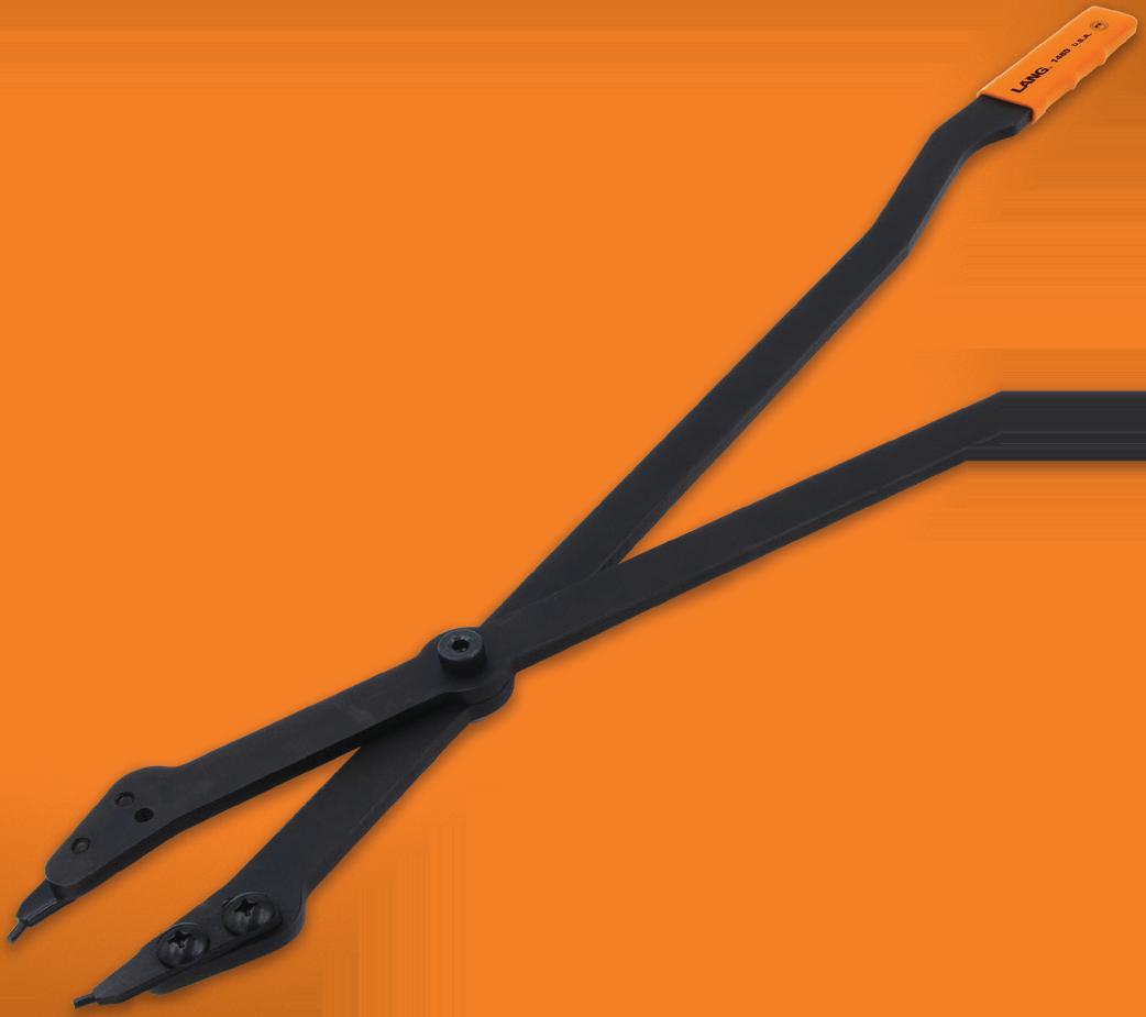
INTERNAL RETAINING RING TWENTY-SIX INCH PLIERS WITH INTERCHANGEABLE TIPS

from Auto Service Professional - February
by EndeavorBusinessMedia-VehicleRepairGroup

Heavy duty pliers used to remove and install the large internal retaining ring in transmission cases
26" handles provide the leverage needed to compress large retaining rings
For use on GM 5L40, 5L50, 6L45, 6L50, 6L80, and 6L90 transmissions


Straight .120" diameter interchangeable tips
GIVING YOU THE LEVERAGE YOU NEED


#
#1489 wiped cam lobe, as well as a restricted exhaust as you will see in this article.
MADE IN U.S.A.
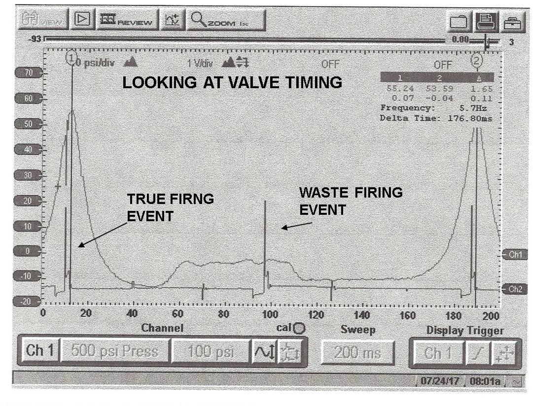
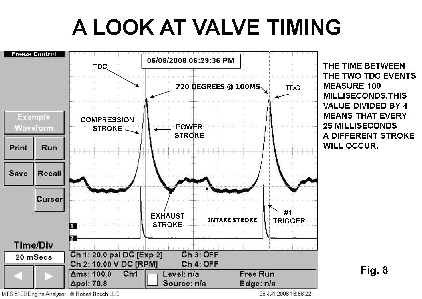
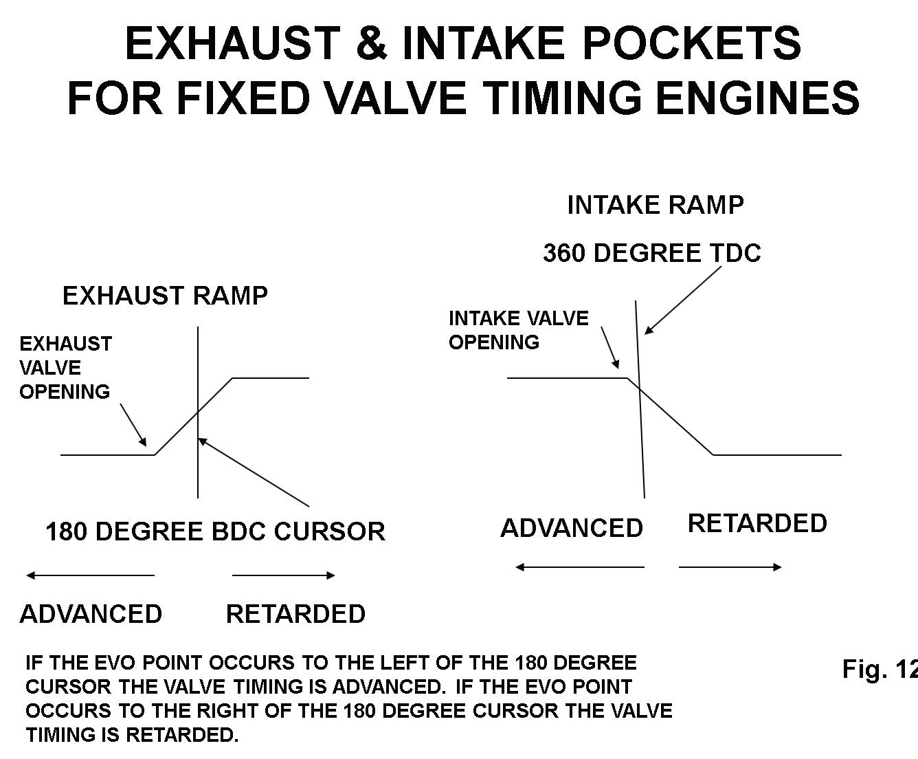
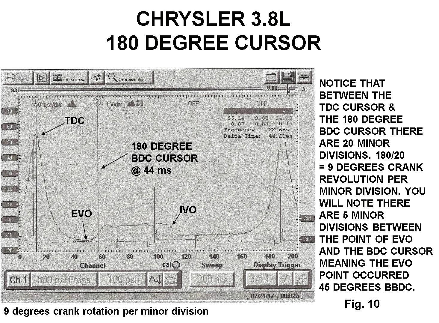
On the high mileage 3.8L Chrysler engine, we captured two TDC events. We now know that the crank has turned 720 degrees. In Fig. 9 notice that the time between the 2 TDC events measures 176 milliseconds. We divide this time by four to represent the four strokes. This means that every 44 milliseconds will represent a different stroke. If we move the first cursor over to the 44-millisecond mark, we just identified the exhaust stroke, or BDC, or 180 degrees. See Fig.10. Notice that the 180-degree cursor pretty much split the exhaust ramp in the middle. Fig. 11 shows where the 180-degree cursor should split the exhaust ramp. Notice on the right of Fig. 11 you can see where the intake ramp should be in relationship to the 360-degree cursor. Fig 12 is where we moved the 360-degree cursor to the 88 millisecond mark which identifies TDC of the intake stroke. This would only apply to engines with fixed valve timing. If the cam timing is off one tooth, the cam timing will be retarded 13 degrees. You may also notice that channel two is indicating the firing event from this cylinder. Notice that the firing event occurred before TDC of the compression stroke. This verifies good spark timing.

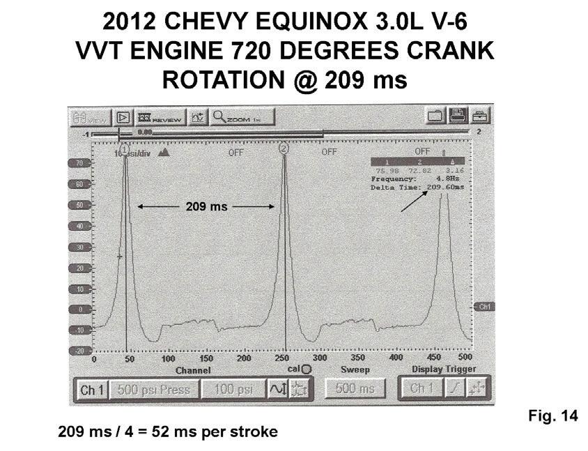
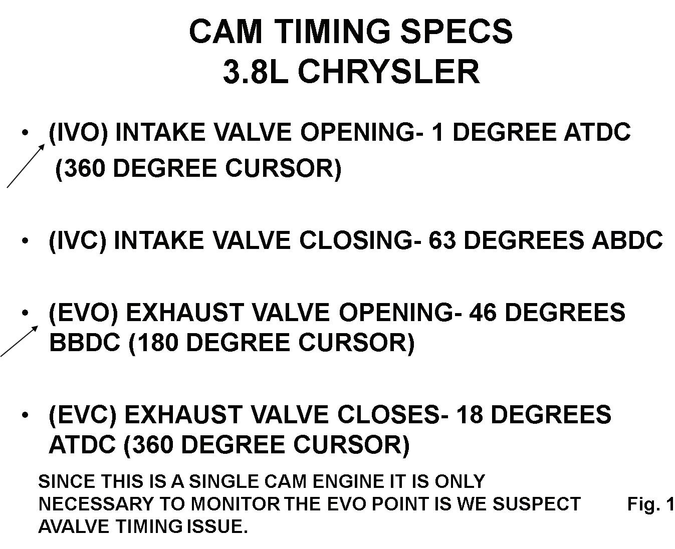
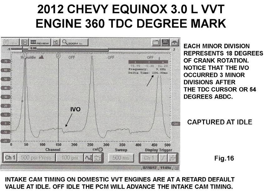
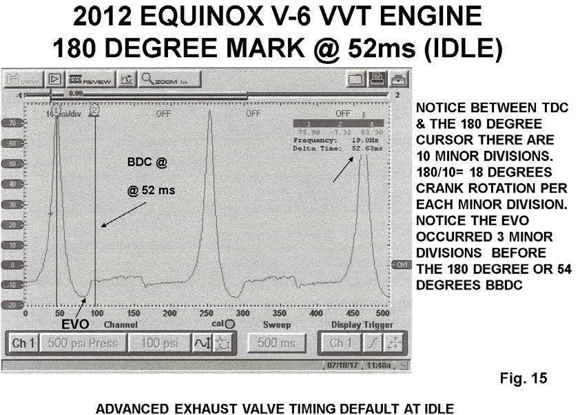
Remember that the WOT snap compression values should match that of the value obtained during WOT cranking. On engines equipped with electronic throttle control, a snap test will not give us 100% throttle opening. The snap test at the accelerator will give us about 40% throttle opening on engines equipped with electronic throttle control, which is a sufficient enough gulp of air that should match what was captured during the WOT cranking compression test. We stated earlier that if the Snap compression test was lower than the WOT cranking compression test, we would suspect a retarded valve timing issue. When performing these tests, it is critical to use a compression gauge that has a maximum length of eight inches. If your compression gauge hose is longer than eight inches your measurements will not be accurate. Fig. 13 shows the valve timing specs for this 3.8L Chrysler engine. Most domestic engines equipped with fixed valve timing will be very close to these specs. You can see in our compression waveforms the valve timing is very close to these specs. events measures 209 milliseconds. We divide this value by four and can determine that each stroke will occur every 52 milliseconds. Fig. 15 is where we placed the second cursor at the 52-millisecond mark which now identifies BDC or the 180-degree mark. You can see that there are 10 minor divisions between the TDC event and the 180-degree cursor. This tells us that the crank turned 18 degrees per each minor division. Notice that the EVO point is advanced and occurred three minor divisions before the 180-degree cursor. Three multiplied by 18 tells us the exhaust cam is advanced 54 degrees at idle. This is a default value captured at idle. Now let’s take a look at the IVO point captured at an idle default position in Fig. 16. Notice that we moved the second cursor to the 104-millisecond mark which identifies the 360-degree TDC mark.
On overhead cam engines, valve timing issues are more common compared to the conventional cam-inblock pushrod engine. You may have an engine such as a SOHC (single overhead cam) engine where we would have to monitor the EVO point on both banks if we suspect a retarded valve timing issue. On engines such as DOHC (double overhead cam) engines we would need to monitor the EVO point and the IVO points on both cams on both banks.
Modern day engines that are equipped with variable valve timing control systems will usually have robust cam timing parameters available via scan data, but you will see that this parameter is unstable as the RPM changes. In the event of wiped cam lobes, we can detect that very easily by viewing the compression waveform. We will show this problem later in this article.
Let’s take a look at a domestic DOHC engine to see what the cam profile looks like. The domestic engines that are equipped with variable cam timing will retard the exhaust valve timing off idle and advance the intake cam timing off idle. This creates valve overlap which increases the engine’s ability to breathe at higher RPMs. This also eliminates the need for EGR systems. During off idle on these engines, the intake valve opening is advanced and the exhaust valve timing is retarded. This allows the engine to pull in some inert exhaust gases which eliminates the need for an EGR system. At an idle condition with a 0% duty cycle command to the VVT control solenoid, the cams will go back to their default condition. The exhaust valve timing goes back to an advanced position while the intake cam timing goes back to a retarded position. Engines imported from Asia do the exact opposite, which allows valve overlap at off idle conditions.
We know that the crank turned 18 degrees per minor division. Notice that the IVO point is retarded and occurred three minor divisions, or 54 degrees, after TDC. Again, these values were captured at idle where the cams come back to their default positions. The domestic engines will retard the exhaust cam timing off idle and advance the intake cam timing off idle.
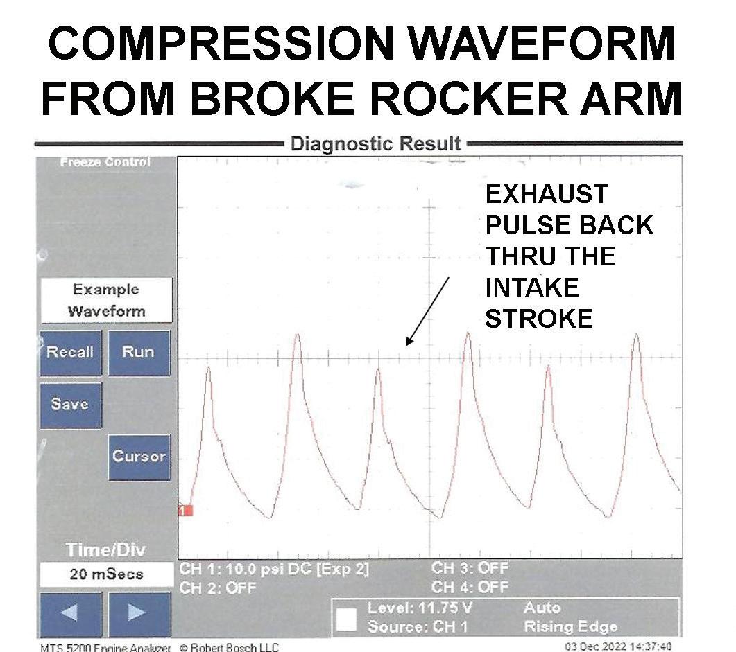
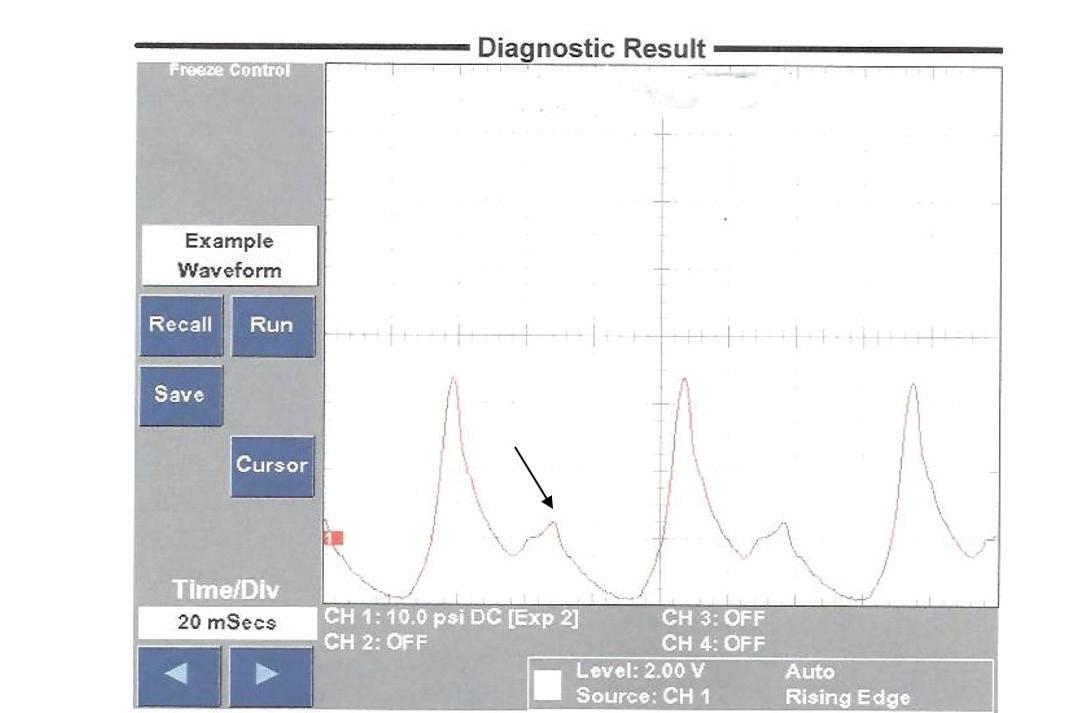
Now let’s look at some problem vehicles. In Fig.17 notice there appears to be two compression strokes. Notice that the second stroke is considerably lower than the first. This waveform was captured from an engine with a broken exhaust valve rocker arm. Since the exhaust valve didn’t open, the exhaust pressure came back through the intake valve on the next intake stroke. We talked earlier that when viewing a compression waveform, we can easily pinpoint a wiped cam lobe which seems to be a common problem on modern day engines. Look closely at the exhaust ramp in Fig. 18. You can easily suspect that the EVO point occurred later. In addition, notice the increase of exhaust pressure at the end of the exhaust ramp. This tells us the exhaust valve opened later and closed earlier from a wiped exhaust cam lobe.
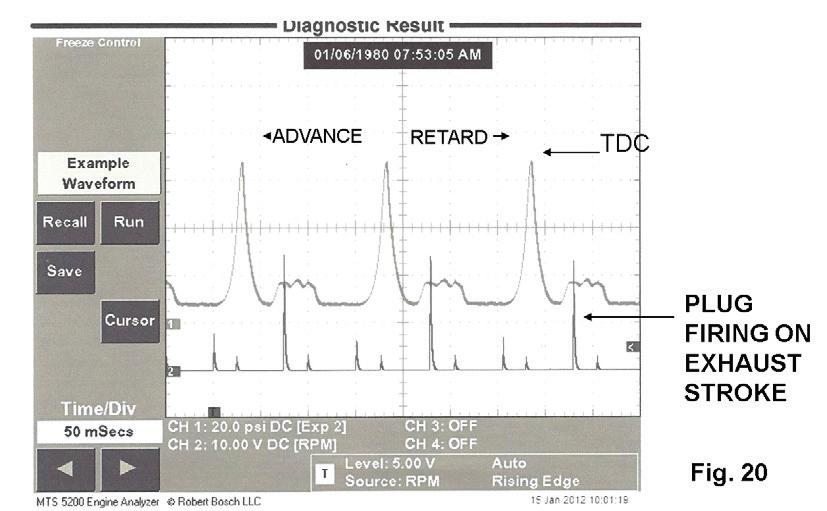
This next example comes from a call from another shop. More often than not, technicians overlook the basics. A high mileage 3.4L engine had a dead miss. Fig. 19 shows a low WOT snap compression value of 66 psi. It would be easy to condemn this engine and recommend the owner pull the plug on this vehicle. Let’s go ahead and look at the compression waveform at idle in Fig. 20. We are triggering from channel two at the plug wire. Did you notice the firing event occurred on the exhaust stroke? Further examination found that two secondary leads were crossed. The low WOT snap compression values were low due to cylinder being washed down with raw fuel which reduces the cylinder sealing ability. This problem occurred after the car owner replaced the coils, secondary leads and spark plugs.
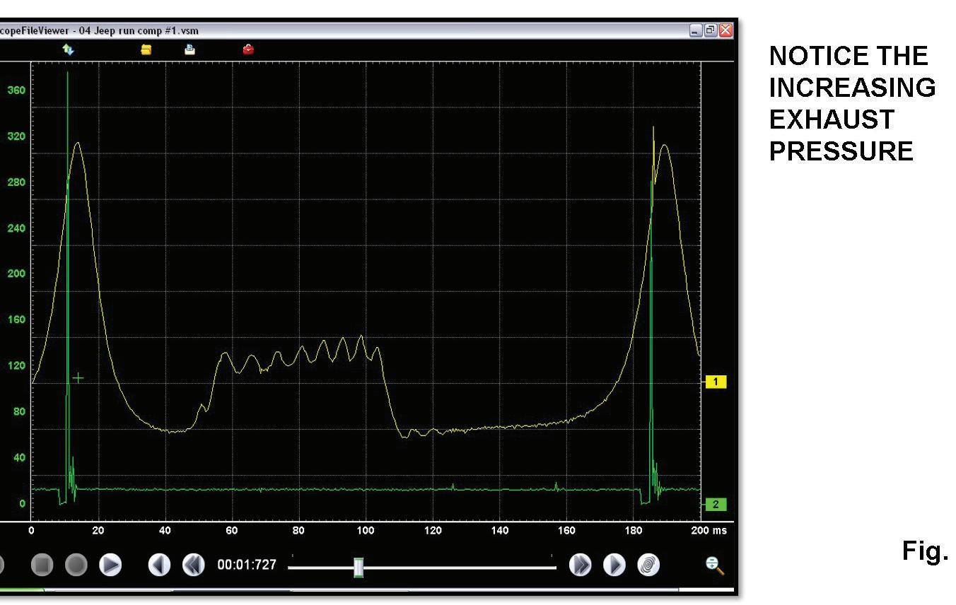
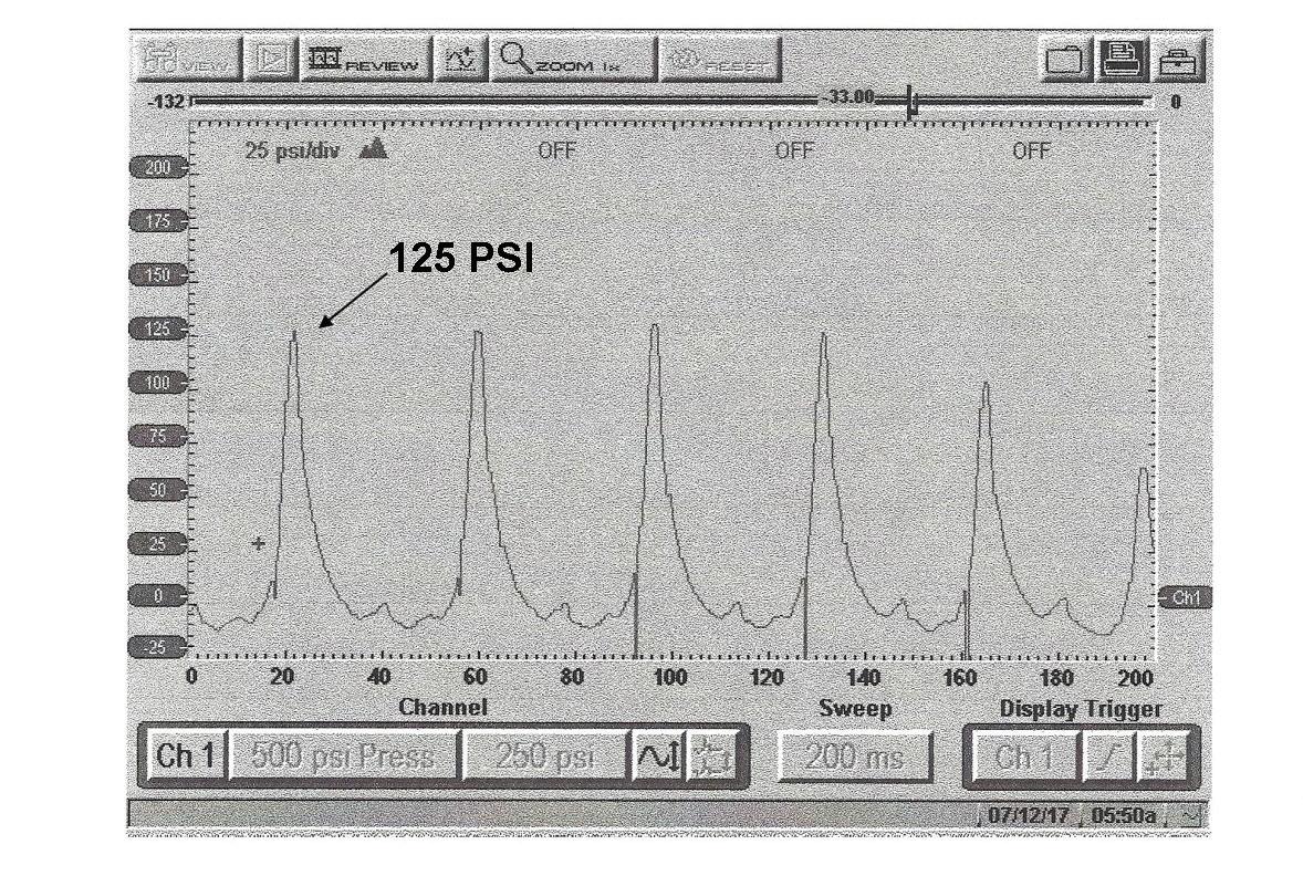
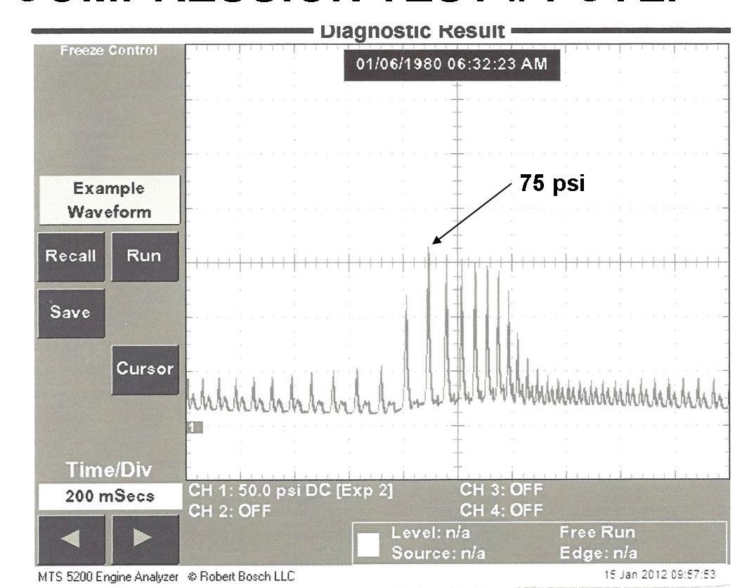
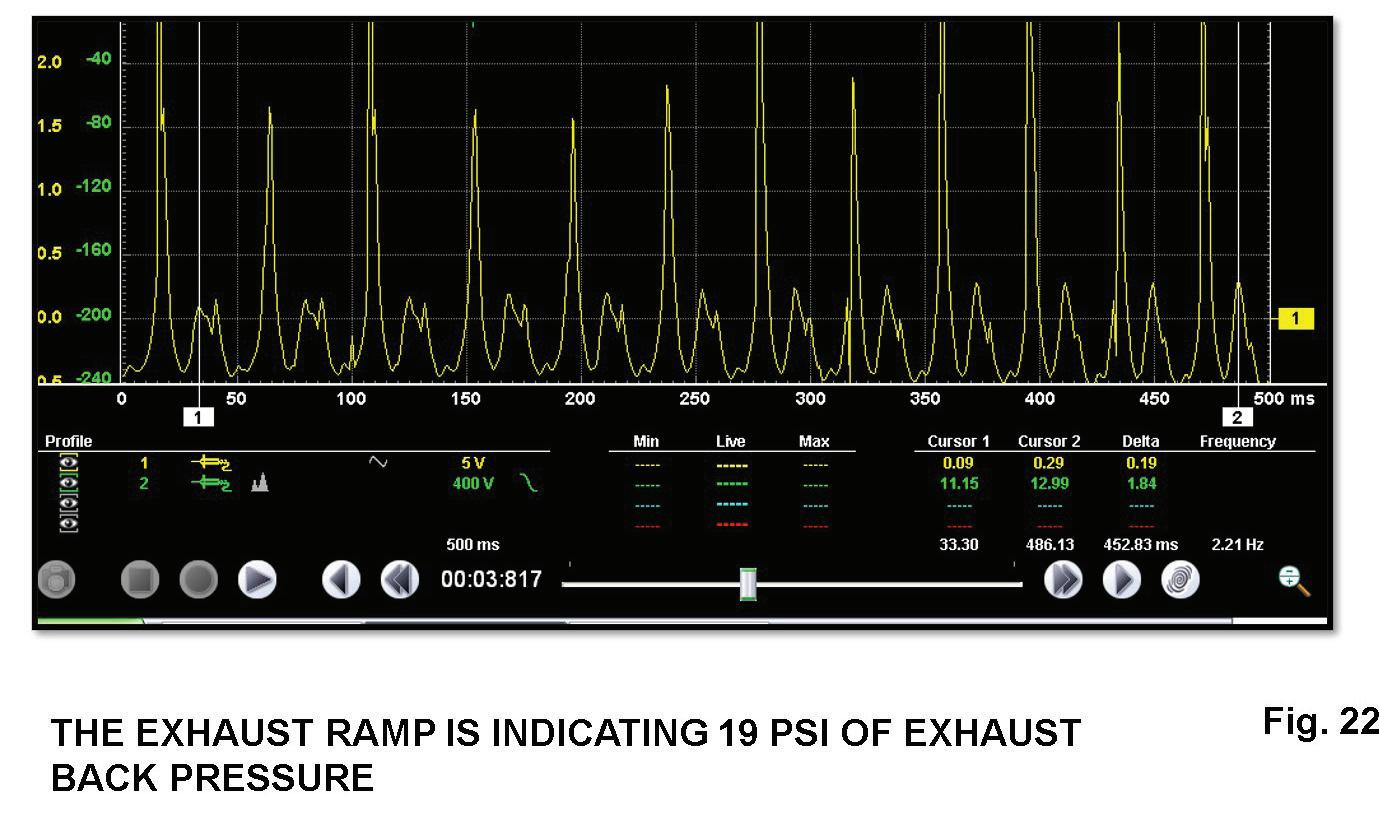
Fig. 21 was captured from an engine suffering from a lack of power complaint. Notice that during the exhaust stroke captured during an idle condition the exhaust pressure is increasing. This was due to a restricted converter. You need to be careful here because a wiped exhaust cam lobe could create the same waveform. However, we previously covered what a wiped cam lobe would look like. Let’s look at a compression waveform captured during a WOT snap test in Fig. 22. Notice the exhaust pressure peaked at 19 psi from a restricted converter.
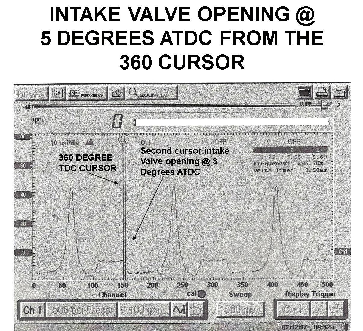
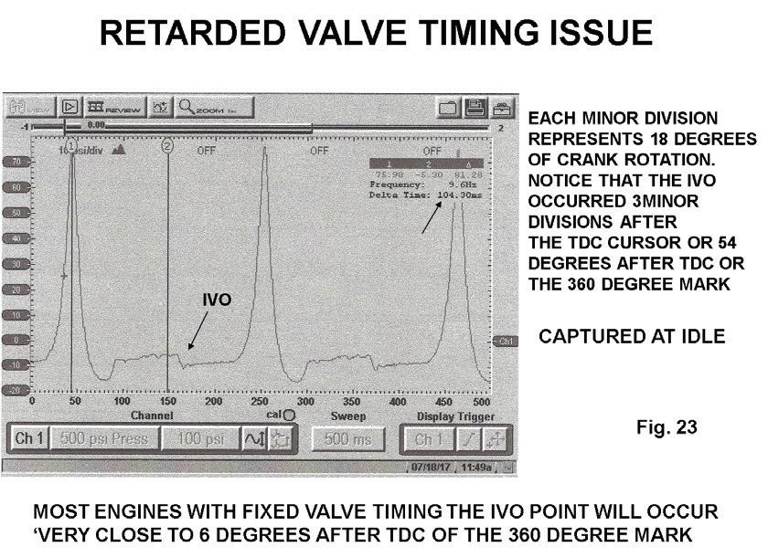
Retarded valve timing issues are becoming more common on today’s modern engines. We previously discussed focusing on the EVO point to pinpoint a retarded valve timing issue. In Fig. 23 let’s focus on the IVO point to determine if we have a retarded valve timing issue. Notice the IVO point occurred after the 360-degree cursor. We established earlier that the crank turned 18 degrees per minor division. Notice that there are three minor divisions between the IVO point and the 360-degree cursor. The valve timing is off 54 degrees. If you refer back to Fig. 11 you can see that the IVO point indicates a retarded valve timing issue.
Fig. 21 This is an example of an engine suffering from a lack of power complaint. Notice that during the exhaust stroke captured during an idle condition that the exhaust pressure increased, due to a restricted catalytic converter.
Fig. 23 We’re focusing on the IVO point to determine if we have a retarded valve timing issue. Notice that the IVO point occurred after the 360-degree cursor. In this example, the valve timing is off 54 degrees. If you refer back to Fig. 11, you can see that the IVO point indicated a retarded valve timing issue.
Testing the engine’s mechanical integrity through the spark plug hole with a pressure transducer will yield a lot of information, and it’s proven to be much easier than an engine tear down. The industry is better because of your commitment.
Fig. 22 While looking at a compression waveform when performing a WOT snap test on the same engine, the exhaust pressure peaked at 19 psi due to the restricted/plugged converter.
Bill Fulton is the author of Mitchell 1’s Advanced Engine Performance Diagnostics and Advanced Engine Diagnostics manuals. He is also the author of several lab scope and drivability manuals such as Ford, Toyota, GM and Chrysler OBD-I and OBD-II systems, fuel system testing, and many other training manuals in addition to his own 101 Lab Scope Testing Tips. He is a certified Master Technician with more than 30 years of training and R&D experience. He was rated in the top three nationally on Motor Service magazine’s Top Technical Trainer Award and has instructed for Mitchell 1, Precision Tune, OTC, O’Reilly Auto Parts, BWD, JD Byrider, Snap-on Vetronix and Standard Ignition programs. You may have also seen Fulton in many Lightning Bolt Training videos and DVDs and read his articles in many auto service magazines. He owns and operates Ohio Automotive Technology, which is an automotive repair and research development center and where the images for this article were produced.