
2 minute read
The Power of Electronic Pressure Transducers

from Auto Service Professional - February
by EndeavorBusinessMedia-VehicleRepairGroup
Avoid an engine tear down with this tool
BY BILL FULTON
THE CONVENTIONAL COMPRESSION gauge was only designed to conduct a WOT cranking compression test. When using this gauge, I have always taught that the second compression stroke is the one that should be monitored. The reason being is that by the second compression stroke we can be assured that a full intake stroke would have occurred. There are cases whereas we could have good WOT cranking compression values and yet the engine may be suffering from a retarded valve timing issue or a wiped exhaust cam lobe. When using the electronic pressure transducer coupled to your original compression gauge hose and interfaced with a DSO, we can conduct four separate compression tests.
It is critical to keep the compression hose as short as possible. I believe that the maximum length should not
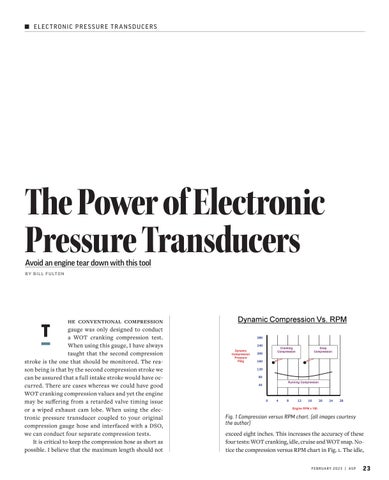
 exceed eight inches. This increases the accuracy of these four tests: WOT cranking, idle, cruise and WOT snap. Notice the compression versus RPM chart in Fig. 1. The idle,
Electronic Pressure Transducers
cruise and WOT snap tests are done dynamically with the engine running. When doing the tests, the Schrader valve needs to be removed from the compression gauge hose. See Fig. 2.

In Fig. 3, we are conducting a WOT cranking compression test with the Schrader valve still intact and the compression gauge hose on a two-valve engine. With each compression stroke the compression values increase. Notice the compression value of 130 psi on the second compression stroke. The second compression value is the one that should be monitored because we know that the piston would have conducted a full intake stroke.

Compression values are measured from the exhaust pocket at 0 psi and up.
Now let’s look at a high mileage 3.8L Chrysler in Fig.4, which shows a WOT cranking compression value of 125 psi. Fig. 5 shows an idle compression value of 45 psi. Next, Fig. 6 indicates a cruise compression value of 35 psi. Finally notice in Fig. 7 that the WOT snap compression test matched the value that was captured during the WOT cranking compression test. If the WOT snap compression test showed a lower value than what was captured during cranking, we would suspect a retarded valve timing issue. The idle and cruise compression values are considerably lower than the value captured during the WOT cranking compression test because the engine is not pulling a lot of air with the throttle plates at an idle condition and barely open during the cruise compression test.


Now let’s take a look at a compression waveform and point out the critical points in Fig. 8.

All four strokes have occurred here between the two TDC events. The time between the two TDC events measures 100 milliseconds. If we divide 100 milliseconds by four strokes we know that a different stroke will appear every 25 milliseconds. The Pico brand DSO has internal software to identify all four strokes. Nevertheless, I prefer to do it the manual way. We have pointed out the exhaust valve opening and the intake valve opening. We may use the abbreviations of EVO for the exhaust valve opening and IVO for the intake valve opening in our scope captures. The point of the exhaust valve opening and the point of the intake valve opening can be monitored to diagnose a retarded valve timing issue or a