HIERARCHY
3.10
a
b
3.13
3.11
3.12
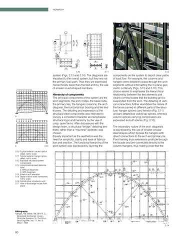
system (Figs. 3.13 and 3.14). The diagonals are important to the overall system, but they are not the primary load path. Thus they are expressed hierarchically lower than the tied arch by the use of smaller round-shaped members.
components on the system to depict clear paths of load flow. For example, the columns and hangers were detailed to pass through the arch segments without interrupting the in-plane geo metric continuity (Figs. 3.15 and 3.16). This choice serves to emphasise the hierarchical relationship between the two elements and clearly communicates that the building grid is suspended from the arch. The detailing of verti cal connections further elucidates the nature of the forces carried in different parts of the struc ture: hanger splices carry tension (Fig. 3.11) and are detailed as visible lap splices, whereas column splices carrying compression are expressed as butt splices (Fig. 3.10).
Hierarchy of components The principal components of the system are the arch segments, the arch nodes, the base node, the primary ties, the hangers /columns, the arch diagonal, the horizontal bar bracing and the end trusses. The detailing and expression of the structural steel components was intended to convey a consistent character and emphasise structural logic and hierarchy by the use of crisp, open forms. After discussions with the design team, a structural “bridge” detailing aes thetic rather than a “machine” aesthetic was chosen. Equally important as the aesthetics was the need for simplicity, clarity and ease of fabrica tion and erection. The functional hierarchy of the arch system was expressed by layering the
The secondary nature of the arch diagonals is expressed by the use of smaller circular steel shapes which bypass the hangers with direct connections to the arch and primary tie. Floor framing truss extensions protrude through the facade and are connected directly to the column /hangers, thus making clear that the
3.10 Typical exterior column splice detail, not to scale 3.11 Typical exterior hanger splice detail, not to scale 3.12 Exposed structural system components 3.13 Unsymmetrical load deforma tions a Without diagonals b With diagonals 3.14 Exterior arch elevation 3.15 Detail of arch node connection, not to scale 3.16 Construction of exterior arch 3.17 View of Exchange House from plaza
Bibliography: Iyengar, Hal; Baker, Bill; Sinn R. C.: Broadgate Exchange House – Structural Systems. In: The Struc tural Engineer, Vol. 71, No. 9, May 4, 1993 3.14
80