

Parker Gen II R-max™ Stream Switching System Catalog 4141-R July 2014 Click to go to Table of Contents
WARNING – USER RESPONSIBILITY
FAILURE OR IMPROPER SELECTION OR IMPROPER USE OF THE PRODUCTS DESCRIBED HEREIN OR RELATED ITEMS CAN CAUSE DEATH, PERSONAL INJURY AND PROPERTY DAMAGE.
This document and other information from Parker-Hannifin Corporation, its subsidiaries and authorized distributors provide product or system options for further investigation by users having technical expertise.
The user, through its own analysis and testing, is solely responsible for making the final selection of the system and components and assuring that all performance, endurance, maintenance, safety and warning requirements of the application are met. The user must analyze all aspects of the application, follow applicable industry standards, and follow the information concerning the product in the current product catalog and in any other materials provided from Parker or its subsidiaries or authorized distributors.
To the extent that Parker or its subsidiaries or authorized distributors provide component or system options based upon data or specifications provided by the user, the user is responsible for determining that such data and specifications are suitable and sufficient for all applications and reasonably foreseeable uses of the components or systems.
Offer of Sale
The items described in this document are hereby offered for sale by Parker-Hannifin Corporation, its subsidiaries or its authorized distributors. This offer and its acceptance are governed by the provisions stated in the detailed “Offer of Sale” elsewhere in this document or available at www.parker.com/ipdus.
© Copyright 2014 Parker Hannifin Corporation. All Rights Reserved.
Parker Hannifin Corporation Instrumentation Products Division Jacksonville, AL USA http://www.parker.com/ipdus
Click to go to Table of Contents Catalog 4141-R
Parker Gen II R-max ™ Stream Switching System
Catalog 4141-R
Table of Contents
Introduction .......................................................................................................................... 2
Features & Specifications.................................................................................................... 2
Actuation Pressure vs. System Pressure 2
Exterior Dimensions 3
Available End Connections ................................................................................................. 3
Valve Module Exploded View 4 Materials of Construction 4
Valve Modules .................................................................................................................... 5
Features 5 Flow Diagram (actuated and un-actuated) 5
Valve Expansion Module ..................................................................................................... 5
Surface Mount Module Disassembly 5
Captured Vent 6
Enhanced Position Indicator................................................................................................ 6
Multiple Stream Switching 7 Fast Loop Options 7
Internal Fast Loop........................................................................................................... 7
Fast Loop Filters 7
Atmospheric Reference Vent (ARV Module) 8
Stream Switch with ARV Module Function ......................................................................... 9 Backwards Compatibility 9
How to Order Stream Switching Systems and Accessories 10 Stream Switching Systems Additional Options............................................................ 10
Stream Switching System Kits 11
Low Pressure Actuator 13
Single Valve ....................................................................................................................... 15
How to Order Single Valve 16 Additional Options 16
Single Valve Kits ........................................................................................................... 17
Fast Loop Filters 18
Exterior View and Dimensions 18 Cross Section View ...................................................................................................... 19 Materials of Construction 19
How to Order Fast Loop Filters 20
Additional Options ........................................................................................................ 20
Fast Loop Filter Kits...................................................................................................... 21
Application: Dual ARV Modules 22
Application: CEMS 23 Base Options for CEMS ............................................................................................... 23
Parker Gen II R-max™ Stream Switching System & Parker IntraFlow™ 24 Offer of Sale 25
Parker Worldwide ............................................................................................... Back Cover
1
Parker Hannifin Corporation Instrumentation Products Division Jacksonville, AL USA http://www.parker.com/ipdus
Parker Gen II R-max ™ Stream Switching System
Parker Gen II R-max ™ Stream Switching System
Introduction
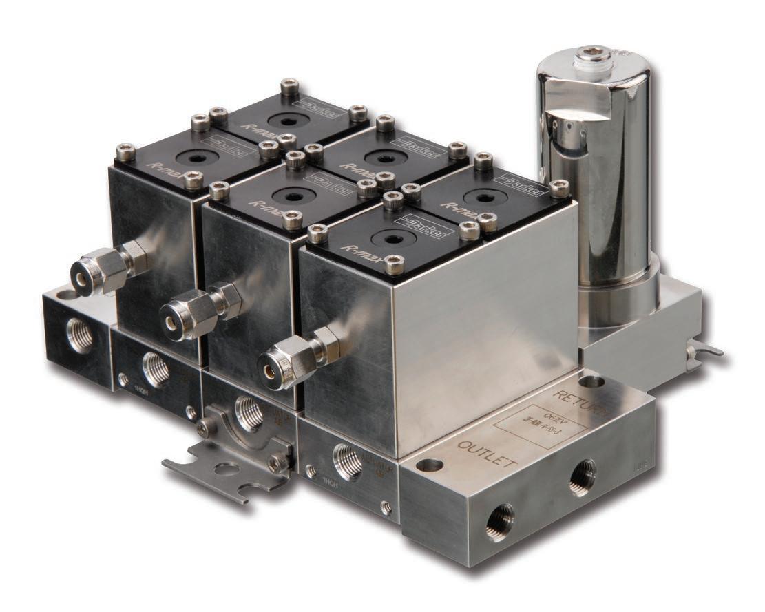
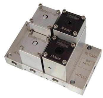
The Parker Gen II R-max™ is a multi-functional system capable of integrating both stream switching and filtering into one unique compact assembly. The system is designed to control both gases and liquids in analytical systems ranging from vacuum to 500 psig (34 bar) while requiring only 65 psig (5 bar) actuating air pressure. The system was engineered with a focus on improved product reliability and reduced cost of ownership. The Parker Gen II R-max™ Stream Switching System utilizes state-of-the-art surface mount technology to reduce leak paths, internal volume, and dead volume. With surface mounting, system components may be easily removed and replaced without breaking process connections. In addition, the Parker Gen II R-max™ system utilizes an internal self-purging outlet header to eliminate the need for an additional outlet loop.
Features
• Captured vent provides a low pressure header that separates sample stream from actuation air preventing cross contamination.
• Enhanced position indicator enables easy recognition of valve position for maximum system safety.
• Backward compatibility allows the enhanced features to be added to existing units.
• Surface mount technology enhances maximum system flexibility and enables the user to add additional streams to a system without interrupting installed units.
• Low internal volume insures maximum system efficiency by reducing purge time and expensive purge gas.
• Modular valve design offers maximum serviceability for quick and easy in-system repair and reduced downtime.
• The Gen II R-max™ is available for ANSI/ISA-76.00.02 (NeSSI) mounting.
• US Patent 6619321
Specifications
Pressure Rating
500 psig (34 bar) CWP
Temperature Rating
Fluorocarbon Rubber –-15°F to 400°F (-26°C to 204°C)
Buna-N Rubber –-30°F to 275°F (-34°C to 135°C)
Ethylene Propylene Rubber –-70°F to 275°F (-57°C to 135°C)
Neoprene Rubber –-45°F to 250°F (-43°C to 121°C)
Highly Fluoronated Fluorocarbon Rubber –-25°F to 300°F (-32°C to 150°C)
Flow Data (in a two stream system)
Stream 1: Cv = 0.154 Stream 2: Cv = 0.104
Actuation Pressure vs. System Pressure
http://www.parker.com/ipdus
2
Click to go to Table of Contents Catalog 4141-R
Parker Hannifin Corporation Instrumentation Products Division Jacksonville, AL USA
3 Parker
Instrumentation
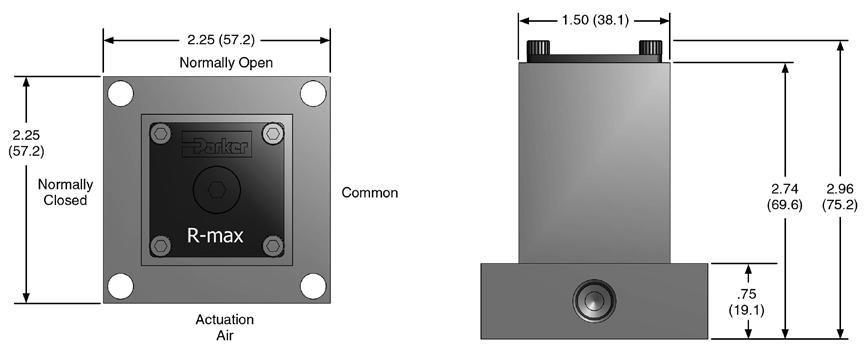
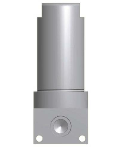
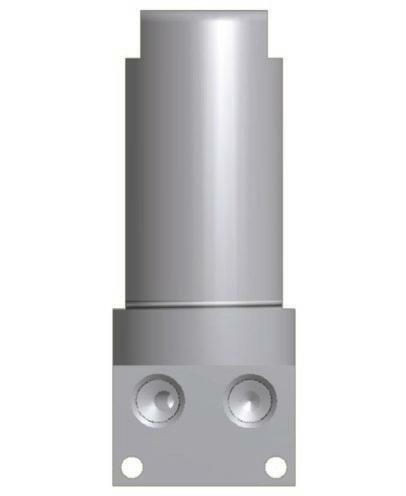
AL USA http://www.parker.com/ipdus Click to go to Table of Contents Catalog 4141-R Parker Gen II R-max ™ Stream Switching System Note: Actuator air porting and vent porting is always 1/8" FNPT. Exterior Dimensions Available End Connections 4A7 – 1/4" inverted two ferrule A-LOK® compression port 2F – 1/8" ANSI/ASME B1.20.1 internal pipe threads 4Z7 – 1/4" inverted single ferrule CPI™ compression port
Hannifin Corporation
Products Division Jacksonville,

4 Parker
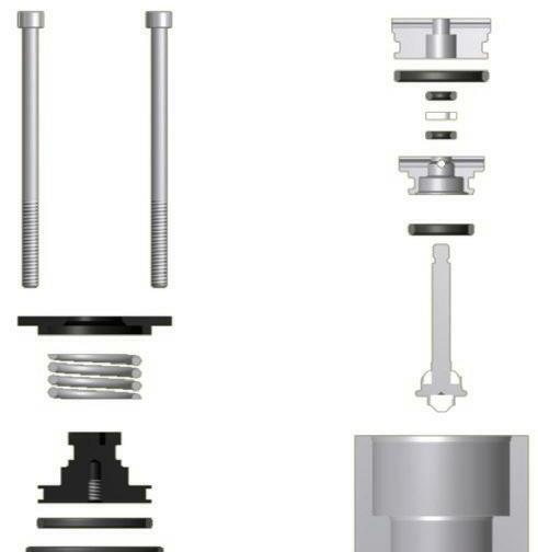
AL USA http://www.parker.com/ipdus Click to go to Table of Contents Catalog 4141-R Parker Gen II R-max ™ Stream Switching System Materials of Construction Valve Module Exploded View Item Part Description Material 1 Base
2 Valve Body
3 Stem
4 Seat PCTFE 5 Backseat PCTFE 6 2-013 O-Ring Optional elastomers 7 Lower Bonnet
8 2-007 O-Ring Optional elastomers 9 Backup Ring PTFE 10 Center
11 2-017 O-Ring Optional elastomers Item Part Description Material 12
13
14
15
16
17
18
19
20
21
Material for
and
Material for
Lubrication: Perfluorinated polyether
Hannifin Corporation Instrumentation Products Division Jacksonville,
ASTM A 479, type 316
ASTM A 479, type 316
ASTM A 479, type 316
ASTM A 479, type 316
Bonnet ASTM A 479, type 316
Upper Bonnet ASTM A 479, type 316
2-018 O-Ring Optional elastomers
2-023 O-Ring Optional elastomers
Piston ASTM B 611, Alloy 6061
Indicator Flexible polyolefin
2-020 O-Ring Optional elastomers
Spring ASTM A 546, type 630
Cap ASTM B 211, Alloy 6061
Bolt (6-32 x 2.25) Stainless steel
Bolt (6-32 x 5/16) Stainless steel Note:
Stream Switching Vent
Analyzer End Plates (not shown) is ASTM A 479, type 316.
Base Plate Bolts is ASTM A 276, type 316.
Parker Gen II R-max ™ Stream
Switching System
Valve Module
The Parker Gen II R-max™ Stream Switching System centers around the Valve Module, which contains two 3-way valves. Each Valve Module is factory mounted to a base plate configured to provide the desired function. The Stream Switching Valve Module provides a double block and bleed arrangement preventing cross contamination of the sample streams.
Valve Module Features
• Each Valve Module has a flow inlet (1/8" FNPT or 1/4" Inverted Compression) and a 1/8" FNPT valve air actuation port.
• Each Valve Module employs two valves.
Valve Module Flow Diagram
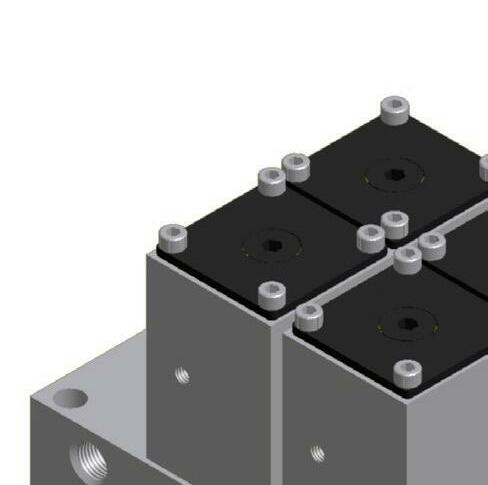
Valve Expansion Module – R3EM
Valve Expansion Modules may be added or removed from the Parker Gen II R-max™ Stream Switching System. The Valve Expansion Module consists of a Valve Module plus two base plate bolts. They may be inserted between the vent and analyzer end plates to add one or more streams to a system. (See How to Order on pages 10-12.)
Note: Valve Modules may only be added to an existing stream switching system.
5
http://www.parker.com/ipdus Click to go to Table of Contents Catalog
Parker Hannifin Corporation Instrumentation Products Division Jacksonville, AL USA
4141-R
Parker Gen II R-max ™ Stream Switching System
Captured Vent
The Parker Gen II R-max ™ is designed with a captured vent header which isolates the sample stream from the actuation air preventing cross contamination. The Captured Vent has 10-32 threads which allows the captured vent to be directed to a containment device.
Porting options include fittings for use with:
• 1/8" plastic tubing

• 1/8" SS tubing
• 1/8" pipe
• 10-32 plug
Enhanced Position Indicator
The Parker Gen II R-max ™ is designed with an enhanced position indicator. The cap and piston are black anodized aluminum. The visual indicator, when actuated open, shows bright yellow against the black background giving easy indication for the open stream.
The visual indicator is also backwards compatible with the R2 Series R-max ™ Stream Select System. Any R-max ™ Stream Select Systems in service can easily be retrofitted with the enhanced indication.
The position indicator can be color coded. Contact the factory for more information.
6
Click to go to Table of Contents Catalog 4141-R
Parker Hannifin Corporation Instrumentation Products Division Jacksonville, AL USA http://www.parker.com/ipdus
Parker Gen II R-max ™ Stream Switching System
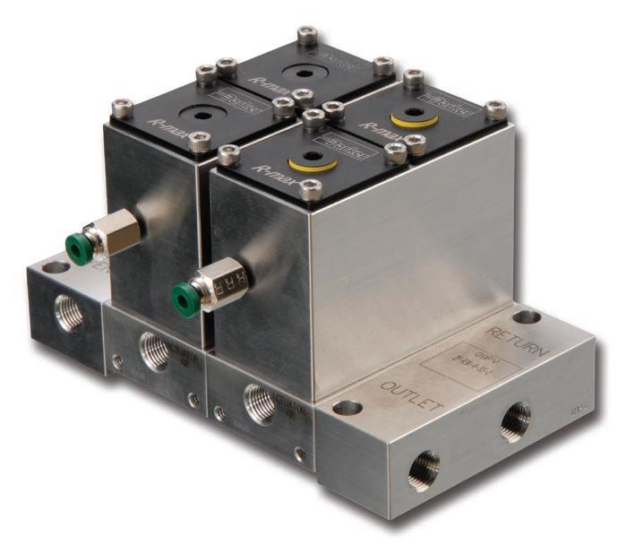
Multi-Stream Switch – R3
A Multi-Stream Switch consists of individual Valve Modules bolted together between vent and analyzer end plates to create an internal, self-purging system with an integral outlet header. This unique design eliminates dead volume and the need for an external loop.

Fast Loop Options
Internal Fast Loop
Example shown is a three stream switching system with an internal fast loop that maintains the double block and bleed feature. Illustrates Streams 1 and 3 in the “off” position, with these two streams flowing to the common vent. Stream 2 is illustrated in the “on” position, closing the bypass and directing the flow to the analyzer. To order, add the suffix -IF to the end of the Stream Switching System part number. (How to Order; see pages 10-12.)
Example: 2F-R3K-BN-SS-3-IF

Fast Loop Filters
Example shown is a three stream switching system with two filter bypasses. Bypass Filter Kits may be incorporated into the Parker Gen II R-max™ Stream Switching System to enhance your system design. (How to Order; see pages 10-12 and 20-21.)
http://www.parker.com/ipdus
7
Click to go to Table of Contents Catalog
Parker Hannifin Corporation Instrumentation Products Division Jacksonville, AL USA
4141-R
Parker Gen II R-max ™ Stream Switching System
Atmospheric Reference Vent (ARV) Module
The Atmospheric Reference Vent Module provides many advantages and benefits within a modular footprint. It can be installed inline with existing Stream Switching Modules or act as a stand alone unit.
When the ARV Module is positioned between the analyzer and stream switching units it allows for sample shut-off and equilibration of the sample loop pressure to atmosphere. This insures a consistent sample volume in repetitive analysis. When the ARV Module is actuated, the sample flows from the actuated (open) stream, through the GC analyzer and is routed to the low pressure header.
The improved features on the Stream Switching Units are included on the ARV Modules. This includes the Captured Vent and Enhanced Position Indicator. It is provided with a new end block which has a dedicated atmosphere reference port. Also, the re-designed ARV Modules can be used with Fast Loop Filtration.

8
Click to go to Table of Contents Catalog 4141-R
Parker Hannifin Corporation Instrumentation Products Division Jacksonville, AL USA http://www.parker.com/ipdus
Parker
Gen II R-max ™ Stream Switching System
Stream Switch with ARV Module Function – Three Stream Examples
Example 1
All valves are in the “off” position. The system is “open” to vent.
Example 2
Stream 2 and the ARV Module are in the “on” position, purging the sample loop to the low pressure header.
Example 3
Stream 2 is in the “on” position and the ARV Module is in the “off” position, equilibrating the sample loop pressure to vent pressure.
Backwards Compatibility
Aspects of the R3 Series Gen II R-max ™ can be applied for use with existing R2 Series units. Retrofitting the existing R2 Series R-max ™ is easily accomplished by following the provided instructions.
Valve Modules: The valve modules are maintained using four 6-32 bolts. Removing these allows the existing R2 Series Module to be removed and the new R3 Series Module to be installed with new 6-32 bolts.
Position Indicator: The Enhanced Position Indicator used on the R3 Series Gen II R-max ™ provides a yellow indicator that is easily identifiable against a black background. This Indicator can be fitted onto the R2 Series R-max ™ for the same easy identification of valve position.
Redesigned ARV (Atmospheric Reference Vent) Option: R2 Series Stream Select Units can be installed with the redesigned ARV End Plate. Note, this also requires a special stream select module to block the ARV Port from the Vent Port.
http://www.parker.com/ipdus
9
Click to go to Table of Contents
Parker Hannifin Corporation Instrumentation Products Division Jacksonville, AL USA
Catalog 4141-R
Parker Gen II R-max ™ Stream Switching System
How to Order Stream Switching Systems and Accessories
The correct part number is easily derived by following the sequence shown below. The eight product characteristics required are coded as shown below.
Example:
2F – R3 K – V – SS – 2 – A E
The example above describes a two stream switching system having 1/8" female NPT inlet and outlet ports, PCTFE valve seats, fluorocarbon rubber seals, stainless steel construction, a fitting for 1/8" plastic tubing on the captured vent port (inlet side) and a 10-32 plug on the other captured vent port.
See page 3.
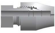
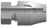
A-LOK® compression D 1/8" FNPT E 10-32 plug F No fitting
The expansion module (EM) option allows for adding additional modules to existing stream switching units. A sample part number for an ARV expansion module is 2F-R3EMK-V-SS-ARV-FF. When adding an ARV expansion module, the base to the adjoining module must be changed for proper function.
10-32
How to Order Additional Options
Oxygen Cleaning: Add the suffix –C3 to the end of the part number to receive stream switching systems or accessories cleaned and assembled for oxygen service in accordance with Parker specification ES8003.
Add the suffix –RTK to the end of the part number to receive stream switching systems or accessories coated with the inert, silicon-based chemical coating Silconert™ 1000 (formerly Silcosteel®).
Add the suffix –SUL to the end of the part number to receive stream switching systems or accessories coated with the inert, silicon-based chemical coating Silconert™ 2000 (formerly Sulfinert®).
NACE: Add the suffix –NC to the end of the part number to receive stream switching systems or accessories that meet the material requirements of ANSI/NACE MR0175/ISO 15156-1.
Internal Fast Loop: Add the suffix –IF to the end of the part number to receive an internal fast loop on all modules. To designate a portion of the total number of modules contact Customer Service.
Low Pressure Actuators: Available factory assembled or as kits for field assembly. Refer to pages 13 and 14 for part number configuration.
Parker Hannifin Corporation Instrumentation Products Division Jacksonville, AL USA http://www.parker.com/ipdus
10
Click to go to Table of Contents Catalog 4141-R
Connection (1) Valve Series Base Options (2) Seat Material Seal Material
Material (3) Number of Modules Captured Vent Fittings (4) 2F 4A7 4Z7
End
Body
R3 Blank None GC ARV Module EM Valve Expansion Module NO Normally Open K PCTFE PK Virgin PEEK VE Vespel V Fluorocarbon Rubber BN Buna-N Rubber EPR Ethylene Propylene Rubber NE Neoprene Rubber KZ Highly Fluorinated Fluorocarbon Rubber SS Stainless Steel Numeric value Blank EM Base Options A 1/8" plastic tubing B 1/8" CPI™ compression C 1/8"
(1)
(2)
(3) Contact Customer Service for availability of exotic alloys such as Monel® and Hastelloy® (4) In the part numbering scheme, the first captured vent letter designator is for the inlet side of the R-max™ Module. All captured vent fittings have a
thread for assembly into the valve body. Seal Material Valve Series Seat Material Base Options End Connection Captured Vent Fittings Body Material Number of Modules Monel® and Hastelloy® are registered trademarks of Special Metals Corporation.
Catalog 4141-R
How to Order Kits
Parker Gen II R-max ™ Stream Switching System
In using this section, the items in BOLD CAPITALIZED PRINT are included within the part number of the Kit. The italicized items require a designator to complete the part number. Refer to the How To Order section on page 10 for the designators.
Stem Seal Kit: Components required to rebuild the soft goods in one cartridge.
Seal Material
R3 Seat Material KIT Body Material
Example: KIT – R3 K – V – SS
This example describes a kit consisting of one stainless steel stem with PCTFE upper and lower seats, fluorocarbon O-rings, associated PTFE back-up rings and maintenance instructions.
Note: This kit is also used for Single Valve Cartridge maintenance.
Valve Module Kit: Components required to rebuild the soft goods in one valve module. This includes the base and cartridges’ seals.
Seal Material
R3 Base Options KIT Body Material Seat Material
Example: KIT – R3 EM K – BN – SS
This example describes a kit consisting of two stainless steel stems with PCTFE upper and lower seats, Buna-N O-rings, associated PTFE back-up rings and maintenance instructions.
Note: For kit part numbers, choose GC, NO and EM for the base option.
Valve Cartridge Kit: Components to replace one valve cartridge.
Seal Material
R3 Seat Material KIT Body Material CART
Example: KIT – R3 K – CART – EPR – SS
This example describes a kit consisting of one completely assembled valve cartridge having PCTFE seats, ethylene propylene O-rings, stainless steel metallic components and maintenance instructions.
Valve Body Kit: Components required to replace one valve body assembly. This includes the cartridges.
R3 Seat Material KIT Body Material BODY
Seal Material
Captured Vent Fittings
Example: KIT – R3 K – BODY – V – SS – FF
This example describes a kit consisting of one complete valve body and cartridge assembly having PCTFE seats, fluorocarbon O-rings, stainless steel metallic components and maintenance instructions.
Note: The springs, screws and caps are included, but not assembled.
Kits continued on the following page.
Parker Hannifin Corporation Instrumentation Products Division Jacksonville, AL USA http://www.parker.com/ipdus
11
Click to go to Table of Contents
Parker Gen II R-max ™ Stream Switching System
How to Order Kits (continued)
Base Seal Kit: Components to replace the soft goods in one base.
R3 Base Options KIT Seal Material BASE
SEALS
Example: KIT – R3 EM – BASE – SEALS – KZ
This example describes a kit consisting of highly fluorinated fluorocarbon O-rings and maintenance instructions.
Note: For the base option, include NO for normally open or GC for ARV options.
End Block Seal Kit: Components to replace the soft goods in one end block.
R3 KIT Seal Material End Block END
SEALS
Example: KIT – R3 – END – SEALS – V
This example describes a kit consisting of fluorocarbon O-rings and maintenance instructions.
Note: For the end block option, choose GC for ARV end blocks .
Position Indication Kits:
The R3 Series Gen II R-max™ Position Indicator is backwards compatible to R2 Series R-max™ Units. Simply remove the piston and cap from an existing R2 Series Cartridge and replace with the R3 Series piston and cap. Functionality and performance will remain the same but will include enhance visual awareness of when the unit is actuated open.
R3 KIT Seal Material EPI
Example: KIT – R3 – EPI – V
This example describes a kit consisting of enhanced visual indicator piston and cap, fluorocarbon O-ring and maintenance instructions.
Captured Vent Fitting Kits:
The R3 Series Gen II R-max™ Captured Vent Header features 10-32 threads on the side of each module. There is a variety of fittings available to direct fluid in this header to a containment device. These fittings can be ordered individually based upon the following part numbers:
Description Part Number (1)
1/8" plastic tubing (2)
1/8" CPI™ compression
1/8" A-LOK® compression
1/8" female NPT
10-32 plug
KIT-R3-CVF-2PLP
KIT-R3-CVF-2Z-V-SS
KIT-R3-CVF-2A-V-SS
KIT-R3-CVF-2F-V-SS
KIT-R3-CVF-PLUG-V-SS
(1) For the elastomer option, choose V, BN, EPR, NE or KZ.
(2) This fitting is nickel-plated brass with a nitrile flat washer.
Parker Hannifin Corporation Instrumentation Products Division Jacksonville, AL USA http://www.parker.com/ipdus
12
Click to go to Table of Contents Catalog 4141-R
Parker Gen II R-max ™ Stream Switching System
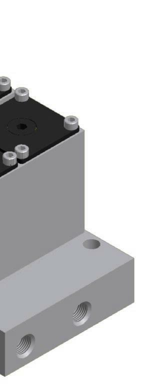
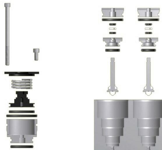
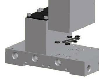
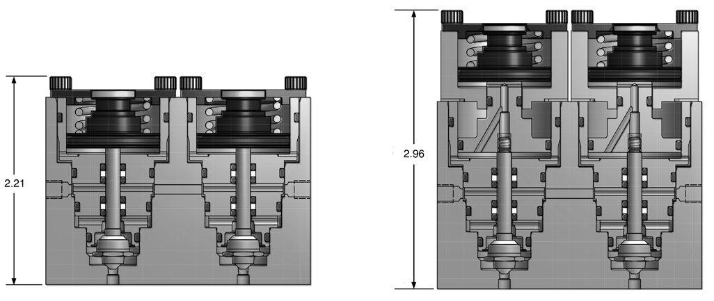
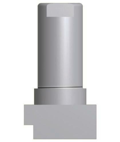
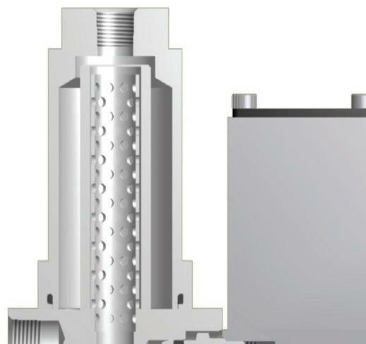
Low Pressure Actuator
The Parker Gen II R-max™ Stream Switching System can be adapted to control both gases and liquids in analytical systems from vacuum to 500 psig while requiring only 35 psig actuating air pressure. The low pressure actuator assembly can be incorporated onto existing R-max™ Stream Switching Systems without affecting existing feature enhancements including the captured vent, enhanced visual indication or backwards compatibility.
Features
• 35 psig actuation air pressure
• Compatible with R-max™ and Gen II R-max™ units
• Factory installed or field retrofitable
• Backwards compatible
• Wide variety of elastomeric seals
• 316 stainless steel construction
• 100% factory tested
Note: The picture highlights the difference between the assembled low pressure actuator and a standard unit on first and second generation R-max™ valves. It is not recommended to use this actuator adapter on a single cartridge within a two cartridge module.
http://www.parker.com/ipdus
13
Click to go to Table of Contents
Parker Hannifin Corporation Instrumentation Products Division Jacksonville, AL USA
Catalog 4141-R
Parker Gen II R-max ™ Stream Switching System
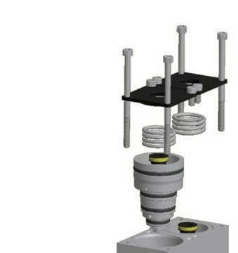
Low Pressure Actuator
The Parker Gen II R-max™ Stream Switching System can be converted into a low pressure actuation unit with the addition of two components and associated seals. All other functional aspects of the R-max™ Stream Switching System remain the same.
How to Order Low Pressure Actuator
For a factory assembled and tested R-max™Stream Switching Systems with the low pressure actuator add the suffix –LP to the end of the part number.
For example: 2F-R3K-KZ-SS-2-FF-LP.
Note: See page 10 for Gen II R-Max™ Stream Switching System part numbering.
For a kit to retrofit an existing unit, whether R-max™ or Gen II R-max™ Stream Switching System, use the following part numbers.
Description Part Number
For R-max™ Stream Switching System
KIT-R2LP-*-SS
For single R-max™ Stream Switching System KIT-R2SLP-*-SS
For Gen II R-max™ Stream Switching System
KIT-R3LP-*-SS
For single Gen II R-max™ Stream Switching System KIT-R3SLP-*-SS
(1)
* Elastomeric options include fluorocarbon rubber (V), ethylene propylene rubber (EPR), buna-n (BN), neoprene (NE) or highly fluorinated fluorocarbon (KZ).
http://www.parker.com/ipdus
14
Click to go to Table of Contents Catalog 4141-R
Parker Hannifin Corporation Instrumentation Products Division Jacksonville, AL USA
Parker Gen II R-max ™ Stream Switching System
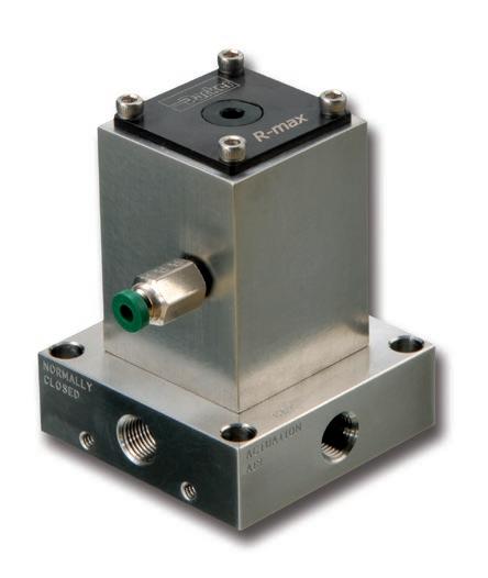
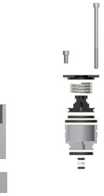
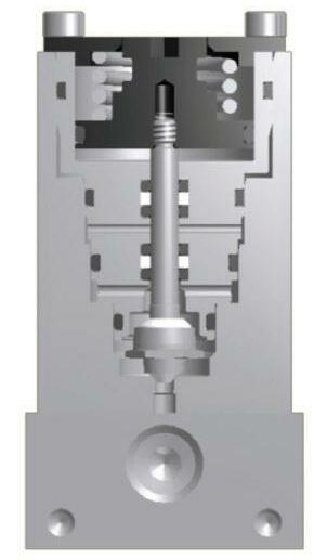
Single Valve
The Parker Gen II R-max ™ Single Valve shares the same technology, features, and options found in the Stream Switching System. The pneumatically actuated valve serves as a three-way diverting valve with common, normally open, and normally closed porting.
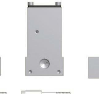
External Dimensions
Exploded View
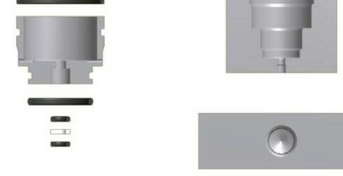
The Single Valve shares similar components with the Double Block and Bleed Unit. With the exception of the Valve Body and Base, the components are identical and can be identified using the numbering system on page 4. Materials are identical and also can be identified on page 4.
15
Click to go to Table of Contents
Parker Hannifin Corporation Instrumentation Products Division Jacksonville, AL USA
http://www.parker.com/ipdus
Catalog 4141-R
Parker Gen II R-max ™ Stream Switching System
How to Order – Single Valve
The correct part number is easily derived by following the sequence shown below. The six product characteristics required are coded as shown below.
Seal Material
Valve Series Seat Material End Connection Captured Vent Fittings Body Material
Example: 2F – R3S K – V – SS – A
The example above describes and a two stream switching system having 1/8" female NPT inlet and outlet ports, PCTFE valve seats, fluorocarbon rubber seals, stainless steel construction and fitting for 1/8" plastic tubing on the captured vent.
End Connection*
2F 4A7 4Z7
Valve Series Seat Material Seal Material
R3S K PCTFE PK Virgin PEEK VE Vespel
* See page 3.
V Fluorocarbon Rubber BN Buna-N Rubber
EPR Ethylene Propylene Rubber
NE Neoprene Rubber KZ Highly Fluorinated Fluorocarbon Rubber
** Contact Customer Service for availability of exotic alloys such as Monel® and Hastelloy®
Body Material**
SS Stainless Steel
Captured Vent Fittings***
A 1/8" plastic tubing
B 1/8" CPI™ compression
C 1/8" A-LOK® compression
D 1/8" FNPT
E 10-32 plug
F No fitting
*** Only one captured vent fitting is required for the single valve. All fittings have a 10-32 thread for assembly into the valve body
How to Order Additional Options
Oxygen Cleaning: Add the suffix –C3 to the end of the part number to receive stream switching systems or accessories cleaned and assembled for oxygen service in accordance with Parker Specification ES8003.
Add the suffix –RTK to the end of the part number to receive stream switching systems or accessories coated with the inert, silicon-based chemical coating Silconert™ 1000 (formerly Silcosteel®).
Add the suffix –SUL to the end of the part number to receive stream switching systems or accessories coated with the inert, silicon-based chemical coating Silconert™ 2000 (formerly Sulfinert®).
NACE: Add the suffix –NC to the end of the part number to receive stream switching systems or accessories that meet the material requirements of ANSI/NACE MR0175/ISO 15156-1.
Low Pressure Actuators: Available factory assembled or as kits for field assembly. Refer to pages 13 and 14 for part number configuration.
Monel® and Hastelloy® are registered trademarks of Special Metals Corporation.
Parker Hannifin Corporation Instrumentation Products Division Jacksonville, AL USA http://www.parker.com/ipdus
16
Click to go to Table of Contents Catalog 4141-R
Parker Gen II R-max ™ Stream Switching System
How to Order Kits – Single Valve
In using this section, the items in BOLD CAPITALIZED PRINT are included within the part number of the Kit. The italicized items require a designator to complete the part number. Refer to the How To Order section on page 16 for the designators.
Stem Seal Kit: Components required to rebuild the soft goods in one cartridge.
Seal Material R3 Seat Material KIT Body Material
Example: KIT – R3 K – V – SS
This example describes a kit consisting of one stainless steel stem with PCTFE upper and lower seats, fluorocarbon O-rings, associated PTFE back-up rings and maintenance instructions.
Valve Module Kit: Components to rebuild the soft goods in one Single Valve Module. This includes the base and cartridges’ seals.
Seal Material
R3S Seat Material KIT Body Material
Example: KIT – R3S K – V – SS
This example describes a kit consisting of one stainless steel stem with PCTFE upper and lower seats, fluorocarbon O-rings, associated PTFE back-up rings and maintenance instructions.
Valve Body Kit: Components to replace one valve body and cartridges.
Seal Material
R3S Seat Material KIT Body Material BODY
Captured Vent Fittings
Example: KIT – R3S K – BODY – V – SS – F
This example describes a kit consisting of one complete valve body and cartridge having PCTFE seats, fluorocarbon O-rings, stainless steel metallic components and maintenance instructions.
Note: The springs, screw and caps are included, but not assembled.
Base Seal Kit: Components to replace the soft goods in one base.
R3S KIT Seal Material BASE
SEALS
Example: KIT – R3S – BASE – SEALS – KZ
This example describes a kit consisting of highly fluorinated fluorocarbon O-rings and maintenance instructions.
Parker Hannifin Corporation Instrumentation Products Division Jacksonville, AL USA http://www.parker.com/ipdus
17
Click to go to Table of Contents
Catalog 4141-R
Parker Gen II R-max ™ Stream Switching System
Fast Loop Filters
Designed to be used on the stream inlet ports of the Parker Gen II R-max ™ Stream Switching System. Multiple filtration options are available using technology developed and designed by Parker Filtration and Separation Divisions. Filtration options include particulate, coalescing and SS sintered.
The particulate filter is housed in a bypass filter that diverts approximately 90% of the inlet flow around the cartridge filter and provides fresh filtered media to the stream switch.
The coalescing filter allows liquid droplets to collect and drain from the media as it enters the stream switch.
The SS sintered filters are designed to protect the Stream Switching System from dirt, chips, scale and other contaminants.
http://www.parker.com/ipdus
18
Click to go to Table of Contents Catalog 4141-R
Parker Hannifin Corporation Instrumentation Products Division Jacksonville, AL USA
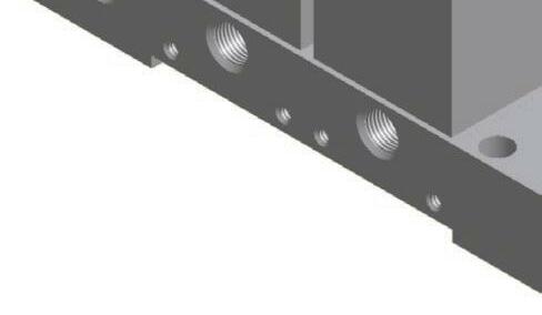
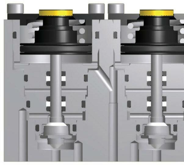
Exterior View and Dimensions


19 Parker Hannifin Corporation Instrumentation Products Division Jacksonville, AL USA http://www.parker.com/ipdus Click to go to Table of Contents Catalog 4141-R Parker Gen II R-max ™ Stream Switching System Cross Section View Materials of Construction Item Part Description Material 1 Body ASTM A 479, type 316 2 Bowl ASTM A 479, type 316 3 Adapter ASTM A 479, type 316 4 O-Ring 2-008 Optional elastomers 5 Body Bolt Stainless steel 6 O-Ring 2-025 Optional elastomers 7 Element 316SS and Microfibre 8 Support Core 316SS Note: The captured vent port nearest an assembled filter must be a plug or an open port. Fast Loop Filters Designed to bolt directly to the stream inlet ports of the Parker Gen II R-max ™ Stream Switching System to provide reduced transport time of filtered sample stream media from the process line through the stream switch to the analyzer.
Parker Gen II R-max ™ Stream Switching System
How to Order – Fast Loop Filters
The correct part number is easily derived by following the sequence shown below. The seven product characteristics required are coded as shown below.
Filtration Type Filter Series Seal Material Inlet and Bypass Outlet R-max ™ Connection Type
Type
Example: 2F – FR2 – EPR – S 100 – SS – B
93 93% microfibre 99 99% microfibre Element
100 100 micron 70 70 micron 40 40 micron 20 20 micron 10 10 micron 5 5 micron Body
The example above describes an FR2 Series Fast Loop Filter with 1/8" FNPT inlet and bypass outlets, ethylene propylene rubber seals, 100 micron 316SS sintered metal filter element and stainless steel construction. It is designed to be attached to a Parker Gen II R-max ™ Stream Switch having inverted CPI™ or A-LOK® stream inlet ports. Inlet
SS Stainless Steel A 2F B 4A7 or 4Z7
Add the suffix –RTK to the end of the part number to receive stream switching systems or accessories coated with the inert, silicon-based chemical coating Silconert™ 1000 (formerly Silcosteel®).
Add the suffix –SUL to the end of the part number to receive stream switching systems or accessories coated with the inert, silicon-based chemical coating Silconert™ 2000 (formerly Sulfinert®).
NACE: Add the suffix –NC to the end of the part number to receive stream switching systems or accessories that meet the material requirements of ANSI/NACE MR0175/ISO 15156-1.
Parker Hannifin Corporation Instrumentation Products Division Jacksonville, AL USA http://www.parker.com/ipdus
20
Click to go to Table of Contents Catalog 4141-R
Series Seal
Filtration Type Element Type Body Material R-max
Connection Type Balston® (P and
Sintered Metal (S)
and Bypass Outlet Filter
Material
™
C)
2F FR2 V Fluorocarbon Rubber BN Buna-N Rubber EPR Ethylene Propylene Rubber NE Neoprene Rubber KZ Highly Fluorinated Fluorocarbon Rubber
P Particulate C Coalescing S Sintered
Material
How to Order Additional Options
Oxygen Cleaning: Add the suffix –C3 to the end of the part number to receive stream switching systems or accessories cleaned and assembled for oxygen service in accordance with Parker specification ES8003.
Parker
Gen II R-max ™ Stream Switching System
How to Order Kits – Fast Loop Filters
In using this section, the items in BOLD CAPITALIZED PRINT are included within the part number of the Kit. The italicized items require a designator to complete the part number. Refer to the How To Order section on page 20 for the designators.
Filter Seal Kit: Components required to replace the O-rings.
Seal Material FR2 KIT
Example: KIT – FR2 – V
This example describes a kit consisting of fluorocarbon O-rings and maintenance instructions.
Filter Element Kit: Components to replace the filter element.
Filtration Type FR2 KIT Element Type
Example: KIT – FR2 – P 93
This example describes a kit consisting of a 93% filtration particulate filter element.
Filter Element & Seal Kit: Components to replace the filter element and O-rings.
Filtration Type FR2 KIT Element Type Seat Material
Example: KIT – FR2 – V – C 99
This example describes a kit consisting of fluorocarbon O-rings, 99% filtration coalescing filter element and maintenance instructions.
Parker Hannifin Corporation Instrumentation
Division Jacksonville, AL USA http://www.parker.com/ipdus
21
Click to go to Table of Contents
Products
Catalog 4141-R
Parker Gen II R-max ™ Stream Switching System
Application: Dual ARV Modules
The Parker Gen II R-max ™ stream selection system can be configured for delivering process stream to multiple Gas Chromatograph inject valves while maintaining the atmospheric reference essential for consistent sample injection. The use of dual ARV (Atmospheric Reference Vent) modules allows the process analyzer engineer to measure a single stream on separate column trains (i.e. parallel chromatography) or use different GC detectors for analyzing specific compound functional groups (i.e. sulfur, halogens, etc.).
The use of dual GC modules demonstrates Parker Gen II R-max ™ valve flexibility and broad application scope for multiple stream selections.
Dual ARV Modules Example 1
All valves are in the “off” position. The system is “open” to atmospheric vent.
Dual ARV Modules Example 2
Stream 1 and ARV Module A are in the “on” position. Sample Inject Valve A is receiving the sample from Stream 1 and is returned to the Low Pressure header through ARV Module A.
For further information, including part numbers, contact the factory.
22
Click to go to Table of Contents Catalog 4141-R
Parker Hannifin Corporation Instrumentation Products Division Jacksonville, AL USA http://www.parker.com/ipdus
Parker Gen II R-max ™ Stream Switching System
Application: CEMS (Continuous Emissions Monitoring System)
The Parker Gen II R-max ™ stream selection system can be configured for Continuous Emissions Monitoring and associated stack gas monitoring applications, analyzer calibration and validation routines that are crucial for maintaining environmental compliance. These environmental regulations require a complete system check and validation which includes the sample extraction probe, transport lines, sample conditioning system, as well as the analyzer.
The complete system check is called an “Up-Stack” calibration. This Up-Stack calibration can be easily achieved by inserting a “diverter” module into the Parker Gen II R-max ™ system. The diverter valve will direct the selected calibration gas either up the stack or allow the gas to go directly to the analyzer. To perform an up-stack calibration simply actuate the diverter valve. Multiple diverter valves can be added if there is more than one stack.
CEMS Example 1
The Calibration Stream 2 is in the “on” position and flowing through the Parker Gen II R-max ™ system and out to Sample Conditioner.
CEMS Example 2
The Calibration Stream 4, Diverter Module and Stream Selector Module are in the “on” position. Calibration gas is flowing through the Diverter Valve to the Stack and then back through the Stream Selector Module to the Sample Conditioner.
How to Order
Example part number: 2F-R3DMSK-V-SS-4-FF
To order the Parker Gen II R-Max™ stream selection system for use in CEMS related applications, the part numbering is identical to the How to Order on page 10 with the exception of the base options. To determine this, choose from the following options.
Base Options Description
DMS Distributor module and standard module
DMSGC Distributor module, standard module and ARV module
http://www.parker.com/ipdus
23
Click to go to Table of Contents
Parker Hannifin Corporation Instrumentation Products Division Jacksonville, AL USA
Catalog 4141-R
Parker Gen II R-max ™ Stream Switching System
Parker Gen II R-max ™ Stream Switching System and Parker IntraFlow™
The Parker Gen II R-max ™ Stream Switching System is also available on the IntraFlow™ ANSI/ ISA-76.00.02 Compliant Modular Surface Mount System. All the features and benefits such as the enhanced visual indicator and captured vent available to the Parker Gen II R-max ™ can also be achieved on the modular platform.
Refer to Catalog 4250 for further information regarding the Parker IntraFlow™ Modular Surface Mount Systems.
All aspects of the Parker Gen II R-max ™ Stream Switching System are available within the IntraFlow™ product line. This includes standard modules, atmospheric reference vent (ARV) modules and normally open modules. Single valve units and filters are also available. The modular design of the IntraFlow™ system allows for maximum flexibility within a minimal space.

http://www.parker.com/ipdus
24
Click to go to Table of Contents Catalog 4141-R
Parker Hannifin Corporation Instrumentation Products Division Jacksonville, AL USA
Offer of Sale
Offer of Sale
The items described in this document and other documents and descriptions provided by Parker Hannifin Corporation, its subsidiaries and its authorized distributors (“Seller”) are hereby offered for sale at prices to be established by Seller. This offer and its acceptance by any customer (“Buyer”) shall be governed by all of the following Terms and Conditions. Buyer’s order for any item described in its document, when communicated to Seller verbally, or in writing, shall constitute acceptance of this offer. All goods or work described will be referred to as “Products”.
1. Terms and Conditions. Seller’s willingness to offer Products, or accept an order for Products, to or from Buyer is expressly conditioned on Buyer’s assent to these Terms and Conditions and to the terms and conditions found on-line at www.parker. com/saleterms/. Seller objects to any contrary or additional term or condition of Buyer’s order or any other document issued by Buyer.
2. Price Adjustments; Payments. Prices stated on the reverse side or preceding pages of this document are valid for 30 days. After 30 days, Seller may change prices to reflect any increase in its costs resulting from state, federal or local legislation, price increases from its suppliers, or any change in the rate, charge, or classification of any carrier. The prices stated on the reverse or preceding pages of this document do not include any sales, use, or other taxes unless so stated specifically. Unless otherwise specified by Seller, all prices are F.O.B. Seller’s facility, and payment is due 30 days from the date of invoice. After 30 days, Buyer shall pay interest on any unpaid invoices at the rate of 1.5% per month or the maximum allowable rate under applicable law.
3. Delivery Dates; Title and Risk; Shipment. All delivery dates are approximate and Seller shall not be responsible for any damages resulting from any delay. Regardless of the manner of shipment, title to any products and risk of loss or damage shall pass to Buyer upon tender to the carrier at Seller’s facility (i.e., when it’s on the truck, it’s yours). Unless otherwise stated, Seller may exercise its judgment in choosing the carrier and means of delivery. No deferment of shipment at Buyers’ request beyond the respective dates indicated will be made except on terms that will indemnify, defend and hold Seller harmless against all loss and additional expense. Buyer shall be responsible for any additional shipping charges incurred by Seller due to Buyer’s changes in shipping, product specifications or in accordance with Section 13, herein.
4. Warranty. Seller warrants that the Products sold here-under shall be free from defects in material or workmanship for a period of twelve months from the date of delivery to Buyer or 2,000 hours of normal use, whichever occurs first. This warranty is made only to Buyer and does not extend to anyone to whom Products are sold after purchased from Seller. The prices charged for Seller’s products are based upon the exclusive limited warranty stated above, and upon the following disclaimer: DISCLAIMER OF WARRANTY: THIS WARRANTY COMPRISES THE SOLE AND ENTIRE WARRANTY PERTAINING TO PRODUCTS PROVIDED HEREUNDER. SELLER DISCLAIMS ALL OTHER WARRANTIES, EXPRESS AND IMPLIED, INCLUDING MERCHANTABILITY AND FITNESS FOR A PARTICULAR PURPOSE.
5. Claims; Commencement of Actions. Buyer shall promptly inspect all Products upon delivery. No claims for shortages will be allowed unless reported to the Seller within 10 days of delivery. No other claims against Seller will be allowed unless asserted in writing within 60 days after delivery or, in the case of an alleged breach of warranty, within 30 days after the date within the warranty period on which the defect is or should have been discovered by Buyer. Any action based upon breach of this agreement or upon any other claim arising out of this sale (other than an action by Seller for any amount due to Seller from Buyer) must be commenced within thirteen months from the date of tender of delivery by Seller or, for a cause of action based upon an alleged breach of warranty, within thirteen months from the date within the warranty period on which the defect is or should have been discovered by Buyer.
6. LIMITATION OF LIABILITY. UPON NOTIFICATION, SELLER WILL, AT ITS OPTION, REPAIR OR REPLACE A DEFECTIVE PRODUCT, OR REFUND THE PURCHASE PRICE. IN NO EVENT SHALL SELLER BE LIABLE TO BUYER FOR ANY SPECIAL, INDIRECT, INCIDENTAL OR CONSEQUENTIAL DAMAGES ARISING OUT OF, OR AS THE RESULT OF, THE SALE, DELIVERY, NON-DELIVERY, SERVICING, USE OR LOSS OF USE OF THE PRODUCTS OR ANY PART THEREOF, OR FOR ANY CHARGES OR EXPENSES OF ANY NATURE INCURRED WITHOUT SELLER’S WRITTEN CONSENT, EVEN IF SELLER HAS BEEN NEGLIGENT, WHETHER IN CONTRACT, TORT OR OTHER LEGAL THEORY. IN NO EVENT SHALL SELLER’S LIABILITY UNDER ANY CLAIM MADE BY BUYER EXCEED THE PURCHASE PRICE OF THE PRODUCTS.
7. Contingencies. Seller shall not be liable for any default or delay in performance if caused by circumstances beyond the reasonable control of Seller.
8. User Responsibility. The user, through its own analysis and testing, is solely responsible for making the final selection of the system and Product and assuring that all performance, endurance, maintenance, safety and warning requirements of the application are met. The user must analyze all aspects of the application and follow applicable industry standards and Product information. If Seller provides Product or system options, the user is responsible for determining that such data and specifications are suitable and sufficient for all applications and reasonably foreseeable uses of the Products or systems.
9. Loss to Buyer’s Property. Any designs, tools, patterns, materials, drawings, confidential information or equipment furnished by Buyer or any other items which become Buyer’s property, may be considered obsolete and may be destroyed by Seller after two consecutive years have elapsed without Buyer placing an order for the items which are manufactured using such property. Seller shall not be responsible for any loss or damage to such property while it is in Seller’s possession or control.
10. Special Tooling. A tooling charge may be imposed for any special tooling, including without limitation, dies, fixtures, molds and patterns, acquired to manufacture Products. Such special tooling shall be and remain Seller’s property notwithstanding payment of any charges by Buyer. In no event will Buyer acquire any interest in apparatus belonging to Seller which is utilized in the manufacture of the Products, even if such apparatus has been specially converted or adapted for such manufacture and notwithstanding any charges paid by Buyer. Unless otherwise agreed, Seller shall have the right to alter, discard or otherwise dispose of any special tooling or other property in its sole discretion at any time.
11. Buyer’s Obligation; Rights of Seller. To secure payment of all sums due or otherwise, Seller shall retain a security interest in the goods delivered and this agreement shall be deemed a Security Agreement under the Uniform Commercial Code. Buyer authorizes Seller as its attorney to execute and file on Buyer’s behalf all documents Seller deems necessary to perfect its security interest. Seller shall have a security interest in, and lien upon, any property of Buyer in Seller’s possession as security for the payment of any amounts owed to Seller by Buyer.
12. Improper use and Indemnity. Buyer shall indemnify, defend, and hold Seller harmless from any claim, liability, damages, lawsuits, and costs (including attorney fees), whether for personal injury, property damage, patent, trademark or copyright infringement or any other claim, brought by or incurred by Buyer, Buyer’s employees, or any other person, arising out of: (a) improper selection, improper application or other misuse of Products purchased by Buyer from Seller; (b) any act or omission, negligent or otherwise, of Buyer; (c) Seller’s use of patterns, plans, drawings, or specifications furnished by Buyer to manufacture Product; or (d) Buyer’s failure to comply with these terms and conditions. Seller shall not indemnify Buyer under any circumstance except as otherwise provided.
13. Cancellations and Changes. Orders shall not be subject to cancellation or change by Buyer for any reason, except with Seller’s written consent and upon terms that will indemnify, defend and hold Seller harmless against all direct, incidental and consequential loss or damage. Seller may change product features, specifications, designs and availability with notice to Buyer.
14. Limitation on Assignment. Buyer may not assign its rights or obligations under this agreement without the prior written consent of Seller.
15. Entire Agreement. This agreement contains the entire agreement between the Buyer and Seller and constitutes the final, complete and exclusive expression of the terms of the agreement. All prior or contemporaneous written or oral agreements or negotiations with respect to the subject matter are herein merged.
16. Waiver and Severability. Failure to enforce any provision of this agreement will not waive that provision nor will any such failure prejudice Seller’s right to enforce that provision in the future. Invalidation of any provision of this agreement by legislation or other rule of law shall not invalidate any other provision herein. The remaining provisions of this agreement will remain in full force and effect.
17. Termination. This agreement may be terminated by Seller for any reason and at any time by giving Buyer thirty (30) days written notice of termination. In addition, Seller may by written notice immediately terminate this agreement for the following: (a) Buyer commits a breach of any provision of this agreement (b) the appointment of a trustee, receiver or custodian for all or any part of Buyer’s property (c) the filing of a petition for relief in bankruptcy of the other Party on its own behalf, or by a third party (d) an assignment for the benefit of creditors, or (e) the dissolution or liquidation of the Buyer.
18. Governing Law. This agreement and the sale and delivery of all Products hereunder shall be deemed to have taken place in and shall be governed and construed in accordance with the laws of the State of Ohio, as applicable to contracts executed and wholly performed therein and without regard to conflicts of laws principles. Buyer irrevocably agrees and consents to the exclusive jurisdiction and venue of the courts of Cuyahoga County, Ohio with respect to any dispute, controversy or claim arising out of or relating to this agreement. Disputes between the parties shall not be settled by arbitration unless, after a dispute has arisen, both parties expressly agree in writing to arbitrate the dispute.
19. Indemnity for Infringement of Intellectual Property Rights. Seller shall have no liability for infringement of any patents, trademarks, copyrights, trade dress, trade secrets or similar rights except as provided in this Section. Seller will defend and indemnify Buyer against allegations of infringement of U.S. patents, U.S. trademarks, copyrights, trade dress and trade secrets (“Intellectual Property Rights”). Seller will defend at its expense and will pay the cost of any settlement or damages awarded in an action brought against Buyer based on an allegation that a Product sold pursuant to this Agreement infringes the Intellectual Property Rights of a third party. Seller’s obligation to defend and indemnify Buyer is contingent on Buyer notifying Seller within ten (10) days after Buyer becomes aware of such allegations of infringement, and Seller having sole control over the defense of any allegations or actions including all negotiations for settlement or compromise. If a Product is subject to a claim that it infringes the Intellectual Property Rights of a third party, Seller may, at its sole expense and option, procure for Buyer the right to continue using the Product, replace or modify the Product so as to make it noninfringing, or offer to accept return of the Product and return the purchase price less a reasonable allowance for depreciation. Notwithstanding the foregoing, Seller shall have no liability for claims of infringement based on information provided by Buyer, or directed to Products delivered hereunder for which the designs are specified in whole or part by Buyer, or infringements resulting from the modification, combination or use in a system of any Product sold hereunder. The foregoing provisions of this Section shall constitute Seller’s sole and exclusive liability and Buyer’s sole and exclusive remedy for infringement of Intellectual Property Rights.
20. Taxes. Unless otherwise indicated, all prices and charges are exclusive of excise, sales, use, property, occupational or like taxes which may be imposed by any taxing authority upon the manufacture, sale or delivery of Products.
21. Equal Opportunity Clause. For the performance of government contracts and where dollar value of the Products exceed $10,000, the equal employment opportunity clauses in Executive Order 11246, VEVRAA, and 41 C.F.R. §§ 60-1.4(a), 60-741.5(a), and 60-250.4, are hereby incorporated.
Parker Hannifin Corporation Instrumentation Products Division Jacksonville, AL USA http://www.parker.com/ipdus
25
Click to go to Table of Contents Catalog 4141-R
01/09
Parker Worldwide
Europe, Middle East, Africa
AE – United Arab Emirates, Dubai Tel: +971 4 8127100 parker.me@parker.com
AT – Austria, Wiener Neustadt Tel: +43 (0)2622 23501-0 parker.austria@parker.com
AT – Eastern Europe, Wiener Neustadt Tel: +43 (0)2622 23501 900 parker.easteurope@parker.com
AZ – Azerbaijan, Baku Tel: +994 50 2233 458 parker.azerbaijan@parker.com
BE/LU – Belgium, Nivelles Tel: +32 (0)67 280 900 parker.belgium@parker.com
BG – Bulgaria, Sofa Tel: +359 2 980 1344 parker.bulgaria@parker.com
BY – Belarus, Minsk Tel: +375 17 209 9399 parker.belarus@parker.com
CH – Switzerland, Etoy Tel: +41 (0)21 821 87 00 parker.switzerland@parker.com
CZ – Czech Republic, Klecany Tel: +420 284 083 111 parker.czechrepublic@parker.com
DE – Germany, Kaarst Tel: +49 (0)2131 4016 0 parker.germany@parker.com
DK – Denmark, Ballerup Tel: +45 43 56 04 00 parker.denmark@parker.com
ES – Spain, Madrid Tel: +34 902 330 001 parker.spain@parker.com
FI – Finland, Vantaa Tel: +358 (0)20 753 2500 parker.fnland@parker.com
FR – France, Contamine s/Arve Tel: +33 (0)4 50 25 80 25 parker.france@parker.com
GR – Greece, Athens Tel: +30 210 933 6450 parker.greece@parker.com
HU – Hungary, Budaörs Tel: +36 23 885 470 parker.hungary@parker.com
IE – Ireland, Dublin Tel: +353 (0)1 466 6370 parker.ireland@parker.com
IT – Italy, Corsico (MI) Tel: +39 02 45 19 21 parker.italy@parker.com
KZ – Kazakhstan, Almaty Tel: +7 7273 561 000 parker.easteurope@parker.com
NL – The Netherlands, Oldenzaal Tel: +31 (0)541 585 000 parker.nl@parker.com
NO – Norway, Asker Tel: +47 66 75 34 00 parker.norway@parker.com
PL – Poland, Warsaw Tel: +48 (0)22 573 24 00 parker.poland@parker.com
PT – Portugal, Leca da Palmeira Tel: +351 22 999 7360 parker.portugal@parker.com
RO – Romania, Bucharest Tel: +40 21 252 1382 parker.romania@parker.com
RU – Russia, Moscow Tel: +7 495 645-2156 parker.russia@parker.com
SE – Sweden, Spånga Tel: +46 (0)8 59 79 50 00 parker.sweden@parker.com
SK – Slovakia, Banská Bystrica Tel: +421 484 162 252 parker.slovakia@parker.com
SL – Slovenia, Novo Mesto Tel: +386 7 337 6650 parker.slovenia@parker.com
TR – Turkey, Istanbul Tel: +90 216 4997081 parker.turkey@parker.com
UA – Ukraine, Kiev Tel +380 44 494 2731 parker.ukraine@parker.com
UK – United Kingdom, Warwick Tel: +44 (0)1926 317 878 parker.uk@parker.com
ZA – South Africa, Kempton Park Tel: +27 (0)11 961 0700 parker.southafrica@parker.com
North America
CA – Canada, Milton, Ontario Tel: +1 905 693 3000
US – USA, Cleveland Tel: +1 216 896 3000
Asia Pacific
AU – Australia, Castle Hill Tel: +61 (0)2-9634 7777
CN – China, Shanghai Tel: +86 21 2899 5000
HK – Hong Kong Tel: +852 2428 8008
IN – India, Mumbai Tel: +91 22 6513 7081-85
JP – Japan, Tokyo Tel: +81 (0)3 6408 3901
KR – South Korea, Seoul Tel: +82 2 559 0400
MY – Malaysia, Shah Alam Tel: +60 3 7849 0800
NZ – New Zealand, Mt Wellington Tel: +64 9 574 1744
SG – Singapore Tel: +65 6887 6300
TH – Thailand, Bangkok Tel: +662 186 7000-99
TW – Taiwan, Taipei Tel: +886 2 2298 8987
South America
AR – Argentina, Buenos Aires Tel: +54 3327 44 4129
BR – Brazil, Sao Jose dos Campos Tel: +55 800 727 5374
CL – Chile, Santiago Tel: +56 2 623 1216
MX – Mexico, Toluca Tel: +52 72 2275 4200
4141-R 07/2014-DDP (7/2014-Duke)
Parker Hannifn Corporation Instrumentation Products Division 2651 Alabama Highway 21 North Jacksonville, AL 36265 phone 256 435 2130 fax 256 435 7718 www.parker.com/ipdus
Your local authorized Parker distributor
Catalog
© 2014 Parker Hannifn Corporation. All rights reserved.
Click
to Table of Contents
to go

