Rolls-Royce V12 ‘Merlin’ to Bentley W12
an illustrated history of engines from Crewe, 1938 – 2024

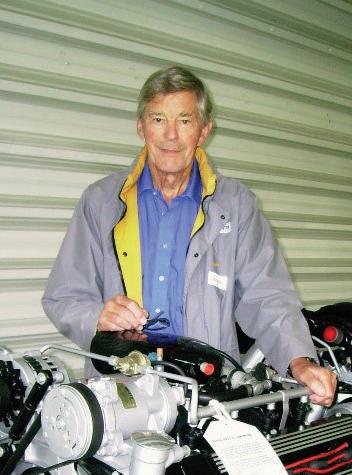
George A Ray
End paper on uncoated white paper (blank)
End paper on uncoated white paper (blank)
End paper on uncoated white paper (blank)

an illustrated history of engines from Crewe, 1938 – 2024
George A Ray
End paper on uncoated white paper (blank)
End paper on uncoated white paper (blank)
an illustrated history of engines from Crewe, 1938 – 2024
George A Ray
Researched and written by George A. Ray, with the permission of Bentley Motors Limited, Pyms Lane, Crewe, CW1 3PL.
© 2024 George A. Ray
Published in the UK by George A. Ray
ISBN 978-?-???????-?-?
All rights to the content of the book belong to George A. Ray and cannot be reproduced or copied without permission of George A. Ray
All rights reserved. No part of this publication may be reproduced, stored in a retrieval system, or transmitted, in any form, or by any means, mechanical, electronic, photocopying, recording, or otherwise without the written consent of the author, nor be otherwise circulated in any form of binding or cover other than that which it is published and without a similar condition being imposed on the subsequent purchaser.
The opinions expressed within are those of the author and not of Bentley Motors Limited.
A catalogue record for this book is available from the British Library.
All photographs and drawings by permission of Bentley unless otherwise marked.
Edited by: Colin Weston and Matthew Waterhouse 2021 - 2024
Formatted, printed and bound by www.beamreachuk.co.uk
Perfection, the ever-moving target ..
.. the engineers’ goal
by SIR DAVID PLASTOW
Retired Chairman and Chief Executive of Rolls-Royce, Bentley Motors and Vickers. Joined Rolls-Royce in 1952 and retired in 1992.

George Ray has carefully reflected the dedication, ingenuity and pride shown by the Crewe motor car division engineers. Their creed and commitment was inherited by all of us from Sir Henry Royce who had declared many years ago "Strive for Perfection in everything that you do". This ultimate goal is continually being raised since it is dependent on the knowledge of the day and the aspirations and opportunities to make improvements that will satisfy any future market place requirements.
The comprehensive coverage of the very extensive engine range is a splendid historic record.
The great diversity of engines described in the book that were designed and developed at Crewe is a credit to all involved. The engineers’ success is admirably demonstrated by the V-8 engine that has now become an icon for its successful production life to power both Rolls-Royce and Bentley luxury cars for more than fifty years. Whilst the other engines may not have gained similar accolades, they have all contributed to the knowledge base and accomplishments of the Company.
I was fortunate to visit Crewe for the first time for many years on 8th April 2014. The meeting with a group of retired engineers was a privilege, and seeing the factory developed to meet production volumes of more than 10,000 cars each year is fantastic. The ownership by the Volkswagen Group is hugely significant ensuring a successful business future.
Sir David was born in Grimsby on 9th May 1932. He became Managing Director of the Motor Car Division in 1971 and Chairman of Rolls-Royce Motors in 1972. He moved, full time, to Vickers plc in 1980 when Vickers acquired Rolls-Royce Motors. Sir David died 5th June 2019.
In 2009, Dr Ulrich Eichhorn, who was a Member of the Bentley Board and the Engineering Director, asked me to help him to research the history of the Crewe designed and manufactured V8 engine. It had powered all RollsRoyce and Bentley cars produced at Crewe for 50 years and he was writing an Engineering Paper for the Institution of Mechanical Engineers, to celebrate the engine’s golden jubilee.
Intrigued by the challenge, I looked forward to meeting many of my retired colleagues from the close-knit Engineering Department as well as liaising with the present members of the Bentley Powertrain Department. This initial investigation has now been complemented by more of the engineers’ stories of this successful V8 engine together with fourteen other internal combustion engines originating at, developed and/or manufactured, in the Crewe factory.
I started my six-year Rolls-Royce ‘student apprenticeship’ at the Pyms Lane factory on 27th September 1955. Initially, I was in production assembly, before quickly moving to the engineering/experimental build and test garage. My first, formal appointment was as a development engineer on vehicle electrical systems. I then became the liaison engineer with the Mulliner/Park Ward division in London to help launch an ‘electrical package of modifications’ and later I covered all aspects of engineering. This coach-building association led me progressively into Trim Development, traditional body structural methods and research into the use of composite materials for body structures. I then became Manager for Vehicle Safety/Crashworthiness including the Company’s design, development and then launch of all passive restraint systems and air-bags. This included relating human ergonomics with both occupant and vehicle packaging, and led finally to the position of Manager for Future Body Engineering. So, this look at engines has been almost a completely new venture for me.
In retirement I have worked as a consultant with Rolls-Royce & Bentley on numerous projects related to body engineering. These have included
the generation of the Bentley Arnage body structure together with occupant and component packaging, several Mulliner Park Ward coach-built vehicles (including the State Limousines) and the early concepts for the Bentley GT range. All these have been through my hands.

I then returned to researching composite materials for use in body structures. Finally, I completely finished at Pyms Lane on 28th February 2013 – after nearly 571/2 years. My entire career has been in the Engineering Department and this has given me a deep engineering background. This has been further broadened during my research for this book giving me greater understanding and appreciation of the work and achievements attained by my ‘Powertrain’ colleagues.
My long service for Rolls-Royce & Bentley (later Bentley, when it was sold to Volkswagen in 1998), has given me the pleasure and privilege of working alongside the engineers responsible for the design, development and, usually, manufacture of the different engine types. This provided one of the most rewarding aspects of my career, by being able to witness the enthusiasm shown by these engineers in their search for continual product improvement. This search continued even when the senior management and ownership of the Company has changed. During the recent transition to VW ownership this has been particularly evident. VW, in return, have readily demonstrated their commitment to the Crewe engineering function and staff.
The powertrain engineers told me about their work and often shared their notebooks, so I have tried to record faithfully their accounts, sometimes
having to consider and debate conflicting versions! Samples of engines and reports that have been saved have also been photographed and included.
During the initial investigation of the history of the V8 ‘L engine’, I also found that there were many associations with all of the different types of engine that the Company has engineered and have usually produced. Whilst each has its own history, the stories are frequently interlinked with engineers transferring from one project to another. I have attempted to recount important engineering aspects for each engine and where possible I have commented on the business rationale for embarking on each venture.
It is similarly recognised that the accomplishment of each of these engine projects was also dependent on the skills and dedication of all the engineers associated with the electrical, electronic, cooling, exhausts and air intake systems without whom, they could not have succeeded. These skills only became integrated in the early 1980s by the introduction of the ‘project-based engineering philosophy'.
Over this 70-year part of the Rolls-Royce and Bentley, Crewe history, the engine work has followed many tortuous paths with numerous diversions due to worldwide economic, government, or legislative changes and, of course, Company policies. Throughout most of this time it has been my privilege as well as my reward to share the pride that the engineers have had in their contributions to the success of the Company.
Several years ago, I was fortunate to become a good friend of the late Mike Evans (1937 – 2016) who gave me a great deal of help and encouragement for this book.
In 1959 Mike joined the Company at Derby as a graduate apprentice to RollsRoyce. As early as 1961 he approached the then General Manager, David Huddie, with the idea of establishing a Company Museum to keep and cherish the Company heritage and prevent ‘over enthusiastic managers’ from giving away or scrapping valuable/unique parts. He then moved into the Public Relations Department and in 1981, together with Engineering Director Roy Heathcote, he founded and later became chairman of the Rolls-Royce Heritage Trust. Even when he relinquished his chairman’s role he continued to visit as a volunteer, contributing his expertise to the museum and Heritage Trust.
During his later working years, his position gave him access to historic documentation including early board minutes. From these records he has written a ‘small and discreet paper’ outlining the events in the early 1930s that describe the sequence of events, with specific reference to the acquisition of Bentley Motors, as well as the then management views. I have had access to this information and have included it in the appropriate paragraphs later in this chapter.
Detailed editing by Colin Weston and Matthew Waterhouse, during 2021 - 2024
Colin Weston
Matthew Waterhouse CEng, FIMechE, CEnv
I joined Rolls-Royce in 1972, specifically to work as a Development Engineer on exhaust emission control having gained extensive experience in this field, particularly with respect to exhaust catalysis, at Ricardo Consulting Engineers, Shoreham-by-Sea and Ford Motor Company at Dunton, Essex. Apart from defining and developing exhaust emission control systems for 1975 MY, which introduced an exhaust catalyst, an early accomplishment was specifying a substantial upgrading of the on-site emission test facilities. During my career at Rolls-Royce I subsequently held the positions of Chief Development Engineer – Engines, Project manager – Powertrain and Chassis Engineering, Acting Chief Engineer –Powertrain and Chassis Engineering and Engineering Project Office Manager. During this time, I managed the N80/81 Engine Project, the initial Sufacon (SuperfastContinental) Car Project Engine/Chassis Development and the conversion of one of the Royal Family Limousines to run on LPG.
I retired in 1997 after 25 years Service although I continued to undertake Consultancy work for a short time.
I joined Rolls-Royce in 1969 in Derby. All undergraduate apprentices started there. But having originally applied to the Motor Car Division in Crewe, I moved there in 1970. After graduating I rejoined Crewe, remaining there until 2001. During this time, I worked initially on the car engine development, before taking charge of the test beds in 1979. Emission testing was added in 1982.
A transfer to vehicle ride and handling and NVH (noise, vibration and harshness) while we introduced the Turbo R broadened my knowledge to other parts of a car. There followed subsequent roles in current model support, manufacturing engineering and defining the future manufacturing strategy to make, efficiently, new models in a low volume environment.
Another change into project management, initially making several special cars made in limited volumes for individual Rolls-Royce or Bentley customers. Finally, after the takeover by the Volkswagen Group, I led the Whole Vehicle Engineering department. I left in 2001.
After leaving Bentley, I worked internationally as a consultant introducing new models for OEMs, individuals and specialist manufacturers. I retired in 2016.
© George A. Ray,
2024
1 Merlin Griffon
3 B40, B60 & 61 B80 & 81
4 F60; Later FB60
5 G60
6 K60
7 Wankel Rotary
Merlin, V12 27 litre Griffon, V12 37 litre aero engines.
In-line 4, 6, & 8 cylinder petrol engines. Used for cars. Also many military and many commercial applications.
In-line 4.2 litre 6 cylinder engine initially for, though never used by, MoD. Used in Vanden Plas Princess R cars.
In-line 4.2 litre 6 cylinder twin OHC engine designed for Healey sports car.
In-line 6 litre 6 cylinder twin crank vertically opposed pistons. Multi-fuel engine.
2 stage rotary engine using the Wankel principal. Designed to be a multi-fuel engine.
8 L V8 Engine. Designed and developed for car applications. A few Commercial & Military uses.
9 M60 & M61
10 FD6 & FD12
In-line 6 cylinder petrol engine. Initially 3.2 litres, increased to 3.7 litres and finally drawn at 4.5 litres.
In-line 6 and U 12. 4.8 litre (6) and 9.6 litre (12). Two-stroke scavenge blown and turbocharged, compression ignition engine. Minimum magnetic signature version for Navy.
11 Light Aircraft Engines New designs and variants of Continental light aircraft 4 and 6 cylinder petrol engines.
12 N80 & N81 V8 petrol engine. Pent roof combustion chamber. Designed as a replacement for L engine.
13 BMW 4.4 litre turbo V8 and 5.4 litre V12.
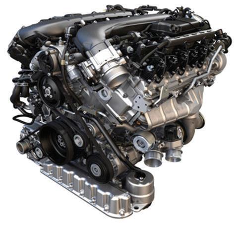
14 W12 TMPI 6.0 litre, 12 cylinder W format. 4 valves/cylinder, Twin OHC, Twin turbochargers.
15 4.0 litre V8 4.0 litre V8. 4 valves per cylinder. Twin OHC and 2 Twin Scroll Turbochargers.
16 W12 TSI
6.0 litre, 12 cylinder W format. 4 valves/cylinder. Twin OHC. 2 Twin Scroll Turbochargers. Twin engine management control units. Stop Start Capability.
Derby design. Built at the newly built Shadow Factory at Crewe from 1938 - 1947.
Initial Derby design 1937. Developed at Clan Foundry, Belper. From 1948 engines engineered, built and tested at Crewe.
Designed 1958. Prototypes 1961. FB60 Production 1964.
Designed 1964. Prototypes 1966 - 69. No production engines made.
Designed 1962. Production 1964 - 65. Rebuilds 1993 - 2003.
Initial Designs 1964. Prototypes 1965 - 74. No productin engines made.
Wide head design 1953. Narrow head design 1955. Major rationalisation and durability upgrades 1986. Complete re-engineer 2010 and 2013.
Designed 1978. No prototypes. No production engines made.
Foden Designs 1939/46. Crewe from 1977. Production and rebuilds 1978 - 2001.
Continental designs 1960. Licenced production and variant engineering from 1962. Service rebuilds 1963 - 80.
Initial design 1985 at 4.25 litres. 1986 N81 at 5 litres. Prototypes all N81 1988-91 at Crewe.
Aluminium crankcase and heads. 4 valves/cylinder, 1 cam per bank. Development throughout life cycle.
Iron crankcase and cylinder head for Military/Commercial uses.
Aluminium alloy head for cars. Petrol, LPG and Nat Gas versions introduced.
Developed at Crewe for car manufacture 1946 - 1959; Military and Commercial engines 1946 - 78.
Aluminium crankcase and head. Carburettors and spark ignition. Designed, developed and manufactured at Crewe, 1964 - 68.
Aluminium crankcase and head. Carburettors and spark ignition. Designed and partially developed at Crewe.
Cast iron crankcase, 2-stroke with vertically opposed pistons. Compression ignition. Designed, developed and manufactured at Crewe for MoD applications.
Initially cast iron then aluminium rotor housings. Compression Ignition. Designed and developed for MoD.
Aluminium crankcase and heads; Carburettors later PI. Spark ignition. Single then Twin Turbochargers. Cylinder de-activation.
Designed and developed for use in all Rolls-Royce and Bentley cars from 1958. Later only Bentley.
Aluminium crankcase and head. Carburettors and spark ignition Designs only for a possible smaller car.
Aluminium crankcase.Cylinder heads in cast iron or special materials. Two stroke compression ignition. Uses Kadency Principal.
Aluminium crankcase and heads, later magnesium heads. Spark Ignition.
Aluminium crankcase and heads. PI. Spark ignition. Twin OHCs. 4 valves per cylinder .
Designed/developed for truck, marine and/or static applications.
Designed, developed and manufactured for use in assorted light aircraft.
Designed and part developed. Stopped due to cancellation of new smaller car. L engine retained in continuing large car
Limited development and modifications at Crewe. Aluminium crankcase and heads; Spark Ignition. Bought from BMW 1997 - 2003.
Initial VW design 1993. Bentley re-design 2000. Production launch 2003.
Joint VW & Bentley design and development 2008/11. Launch 2013.
Joint VW & Bentley design and development 20011/15.
Aluminium crankcase and heads. Multi point Injection. Spark ignition. Bio-fuel capability. Designed, developed, built and tested at Crewe.
Aluminium crankcase and heads; Spark ignition. Hot central V with exhaust and turbochargers in V.
Aluminium crankcase and heads. Spark Ignition. Dual Injection System. Oil system with variable capacity pump capability. Cylinder Deactivation.
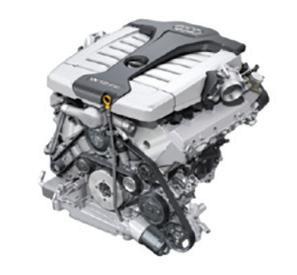
Designed and developed jointly with Audi.
Designed, developed, built and tested at Crewe. Production launch late 2015. Last internal combustion engine built at Crewe 2024.
All are current (or ex) Crewe, Rolls-Royce and Bentley engineering personnel. (Unless otherwise identified.)
Bernie Arger, John Astbury; Simon Baron-Oxberry; Norbert Becker; Ron Biggins; Bryan Chetwyn; Tom Creer; Neville Daniel; Mike Dunn; Rod East (Fodens); Alan Edge; Paul Edwards; Dr Ulrich Eichhorn; Howard Evans; Mike Evans (Founder and Chairman Emeritus of RRHT); Michael Fleiss; David Garside MBE; Gary Greenwood; Brian Gush; Ian Hassall; David Hassall; (Fodens then Rolls-Royce and Bentley); Chris Hughes; John Humphreys; John Humphries; Alan Jobson; Ken Lea; Brian Leverton; Reg Lewis; (Fodens); Les Maddock; Ian Malpas; Ashley Mason; Trevor Park; Roy Penlington; Bill Porter; David Preece; Chris Price; Dr Bryan Roe; Mike Sayer; Tim Seipel; Paul Shore; Graham Smith; Alan Sockett; Reg Spencer MBE; Graham Starling; Bruce Sutherland; Matthew Waterhouse; Colin Weston; Jonathan Wigston; Mike Wilson and Derek Wright.
A table listing the length of service and responsibilities of the Rolls-Royce and Bentley, Crewe contributing personnel is opposite. It is worthwhile commenting that nearly 1400 man-years of service have been accumulated between all the contributing engineers (by the end of 2024) i.e., an average of approaching 30 years each.
Many more colleagues also advised and confirmed the veracity of the information.
In recent years their contributions have been complemented by information, documents and presentations that have been published by the VW Group with whom there has been extensive collaboration particularly for the 4.0 litre V8 and W12 engines (Chapters 14, 15 and 16) and grateful recognition is given to Dipl.–Ing. Friedrich Eichler, Dr Wolfgang Demmelbauer-Ebner and Dr Dipl.–Ing. Jens Kűhlmeyer from Volkswagen AG, Wolfsburg.
With acknowledgements and special thanks for their co-operation, to Bentley Motors Limited whose management and Powertrain department personnel have given me great assistance with the more recent engines.
I must also thank The Foden Society, Rolls-Royce Distribution Generation Systems, The Rolls-Royce Heritage Trust, The Sir Henry Royce Memorial Foundation and the Royal College of Military Science.
Finally, I must record the encouragement that I received from, as well as the information provided by, the late Mike Evans regarding the early years of RollsRoyce and how the integration of W. O. Bentley into the Company took place.
Name Service Years
Bernie Arger 1969 - 1974 1978 - 1999 26
Job Description / Positions Held and Crewe Engine Experience
Development Engineer Chassis/Driveline - Development Engineer SLAED - Product Engineer - Cosworth Technology Ltd. (As part of R-R)
John Astbury 1956 - 1991 35 Engine Designer - Deputy Chief Engineer Engines - Chief Engineer Powertrain - Manager Future Programmes
Simon Baron-Oxberry 2002 - 2018 16 Functional Manager - Engine Mechanical Development
Norbert Becker 2004 - 2008 4 Function Manager - Engine Calibration
Ron Biggins 1950 - 1985 35 Engine Project Designer
Bryan Chetwyn 1956 - 2001 24 Engine Dev Engineer - Blue Streak Rocket Development - Senior Engine Dev Engineer
Tom Creer 1963 - 2001 38 Metallurgist - Manager of Laboratory and Process Engineering
Neville Daniel 1951 - 1970 19 Assistant Chief Product Engineer, Motor cars & Light Aircraft Engines
Mike Dunn 1983 - 1992 9 Engineering Director
Dr Ulrich Eichhorn 2003 - 2011 8 Engineering Director
Alan Edge 1980 - 2015 35 Engine Detail Draughtsman - Engine Designer - Powertrain Design Engineer - Powertrain Project Designer - Special Projects Engineer MPW - Design Engineer W12TMPI
Paul Edwards 1975 - 2010 35 Emission Technician - Manager Whole Vehicle Validation
Howard Evans 1969 - 1982 2008 - 2018 23
Apprentice, Electrical/Electronic Engineering - Electrical Dev Engineer - Senior Electrical Dev Engineer - Assistant Chief Electrical Dev Engineer - Functional Manager, Electrical Distribution
Michael Fleiss 2001 - 2016 15 Engine Calibration
David Garside MBE 1960 – 1963 1965 - 1967 5 Graduate Apprentice Development Engineer - Senior Development Engineer
Gary Greenwood 1975 – 2016 41 Dev Engineer Heat Shields, Fuel, Cooling & Exhaust Systems - Dev Engineer Product Support (Brakes, Hydraulics & Suspension)Gearbox Calibration & Dynamics
Brian Gush 1999 – 2019 20 Chief Engineer Engines - Head of Motor Sport
Les Griffin 1943 - 1982 39 Section Leader Detail Design
David Hassall 1980 - 2002 22 Development Engineer SED - Project Engineer - Interior Trim Designer - Coachbuilt Car Lead Engineer - Cockpit Lead EngineerCar Interior Systems Principal
Ian Hassall 1974 - 2009 35 Engine Tester - Emissions Lab Technician - Dev Engineer - Senior Dev Engineer - Engine Calibration Engineer
Chris Hughes 1966 - 2002 36 Engine Development Engineer
John Humphreys 1947 - 1992 43 Specialist Engine Designer - Assistant Chief Engine Designer
John Humphries 1985 - 2013 28 Powertrain Dev Engineer/Manager - Engine Test Manager - Engine Design Manager
Alan Jobson 1946 - 1967 21 Engine Designer - Design Engineer - Industrial Sales
Ken Lea 1983 - 1990 7 Chief Engineer Powertrain - Manufacturing Director - Current Model Engineering Director
Name Service Years
Job Description / Positions Held and Crewe Engine Experience
Les Maddock 1961 - 1997 36 Engine Designer - Engine Design Manager - Engineering Manager Current Models
Ian Malpas 1984 - 2020 16 Functional Manager Engine Design W12
Trevor Park 1984 - 2014 30 Powertrain Development Engineer - Head of Powertrain Management
Roy Penlington 1959 - 1992 33 Experimental Engine Builder - Technical Writer - Head of Technical Publications
Bill Porter 1942 - 1987 45 Engine Designer - Senior Powertrain Development Engineer
David Preece 1959 - 2010 51 Experimental Engine Builder - Forman Emission Test - Quality
Dr Bryan Roe 1978 - 2002 24
Metallurgist - Executive Engineer, Electrical EngineeringSystems Manager Bill of Material & Engineering Change Mike Sayer 2006 - 2024 18
Calibration
Roman Sitek 1969 - 1980 11 Emissions Lab Technician - Service Engineer Light Aircraft Engines
Reg Spencer MBE 1940 -1985 45 Senior Engine Designer (B Range, L Engine, F60) - Divisional Chief Inspector
Graham Starling 1968 - 2006 38 Dev Engineer - Assistant Chief Dev Engineer - Manager Legislation & Certification
Bruce Sutherland 1965 - 2005 39 Dev Engineer HVAC - Manager HVAC, Engine Cooling, Brakes Aerodynamics, Driveline & Throttle etc - Functional Manager HVAC
Ken Trinder 1952 - 1990 38 Engine/Electrics Designer & Certification
Matt Waterhouse 1969 - 2001 32 Engine Dev Engineer - Head of Whole Vehicle Engineering
Colin Weston 1972 - 1997 25 Dev Engineer - Chief Dev Engineer - Engine – Project Manager N80/ N81 & Sufacon – Head of Powertrain Engineering
Jonathon Wigston 2001 - 2024 23 Functional Manager - Test Operations
Mike Wilson 1968 - 2005 37 Dev Engineer, Safety - Emission Certification - Manager Emission Test – Emission Certification Specialist
Derek Wright 1951 - 1991 40
Engine Designer - Senior Engine Designer - Engineering Manager, Diesel Products (Engine Design, Development & Quality)
The B Range of engines was conceived in 1937 at Clan Foundry, near Derby, as a range of 4, 6 and 8 cylinder in-line engines using as many common parts as possible. While using many features from earlier engines, the key change was to overhead inlet/side exhaust valving. This change was driven by the need to increase valve and port size while maintaining the cylinder spacing dimension of 4.150in initiated with the RR 20 engine (Goshawk) in 1920 (see appendix 2 below). This design was part of a rationalising programme that was initiated

for both cars and engines during the mid-1930s, following the death of Sir Henry Royce in 1933.
During the late 1940s through to the mid 1950s, the 6-cylinder engines were used to power all the cars built at Crewe. They were also sold as power units for military vehicles in 4, 6 and 8 cylinder form.
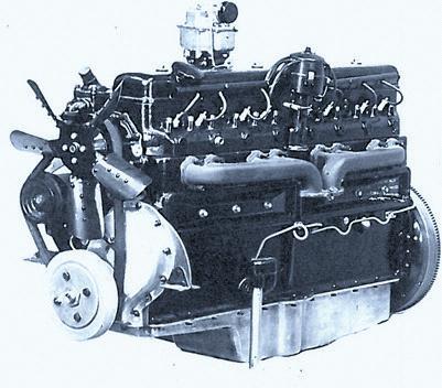
However, as early as 1938 an 8 cylinder in-line engine that had triple SU carburettors was fitted to an experimental car that was christened the ‘Scalded Cat’ due to its extremely high performance. A small number of such experimental vehicles were made with the intention of making the concept the basis of large limousines for Royalty or other foreign VIPs.
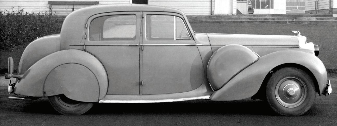
The car was built in 1939 and was fitted with a prototype B80 engine. It had extremely good performance for that era and was shipped to Canada for safe keeping during World War II. Post war a second car was built and used to transport, or even be loaned to, VIPs and royalty.
Note the very long bonnet that was required to accommodate the B80 engine. This feature was later heeded during the debate on what engine format should succeed the B60 range of engines for production cars and was one element that led to the choice of the shorter V8 rather than adopt a straight 8 engine.
As a way of promoting the car to the Royal family, Scalded Cat was loaned to the Duke of Edinburgh who enjoyed the driving experience so much that it became difficult to retrieve the car.
One experimental vehicle, designated 3-B-50, was the first vehicle to have the 6 cylinder B range engine (number 4) as original fitment. And one car has survived. It is still fitted with an experimental B-60 engine (number 11).
Another of these early experimental vehicles was quite dramatically altered when it was rebuilt into a small truck that ran until 1963. By the end of its life, it had accumulated a high mileage and had successfully demonstrated the reliability of the engine.
This was 4AF-4 which had been built as a Rolls-Royce car fitted with an in-line 8 cylinder engine.
This was converted into a ‘pickup truck’ that was used in the late 1940s and through the 1950s by the Crewe transport and experimental departments as a fast parts delivery and test vehicle. It also had the facility for mounting a camera tripod on its back so that action photographs/film of the suspension etc. of a following test car could be taken. This was a
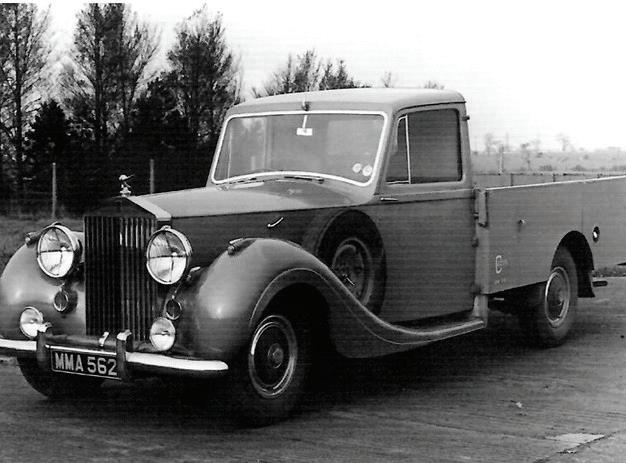
challenge for the camera man with no safety harness being provided when doing speeds of up to 80mph on the chosen bumpy and winding roads.
This general use was ideal to accumulate mileage and many hours of endurance testing on the engine until it was dismantled in 1963.
By the late 1940s there was a growing demand for more power particularly for cars destined for the European market. This led to extensive development that eventually increased the swept volume first to 4.566 litres (known as the Big Bore engine) then to 4.887 litres for the engine that powered the famous lightweight and streamlined Bentley R-Type Continental with its top speed of 120mph. This engine was then deemed adequate for the launch of the Silver Cloud and S Series in 1955.
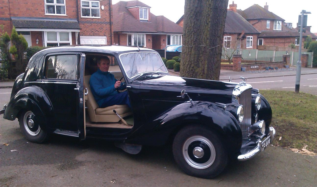
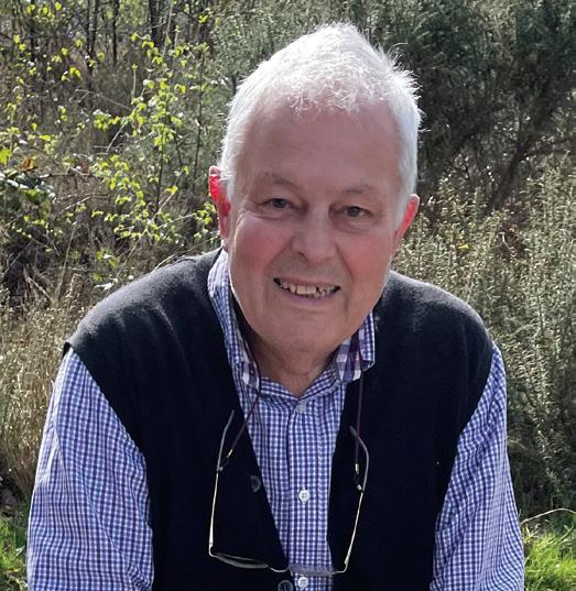
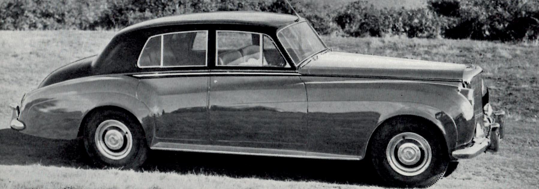
Rob Galloway, one of the contributors to this book, ‘at the wheel’ of BVI, (B101GT). Rob worked for Rolls-Royce and Bentley from 1980 to 2009, initially as a quality engineer and later as leader of the Manufacturing Engineering team responsible for assembly and test bed equipment required for the V8 and W12 engines.
In 1950, retired Rolls-Royce Crewe engineer Rob Galloway’s grandfather bought the car illustrated here as a nearly new, ex-demonstrator vehicle. It was inherited by Rob’s father in 1965 and was subsequently passed on to Rob and his brother, in 1983. He has both the pleasure of using the car, but also the duty of keeping it well maintained.
In 1943, a B80 was demonstrated to the Ministry of Supply in a Bren Gun carrier tracked military vehicle by Robotham following his return from the Rolls-Royce, Nottingham factory. This was the start of the Company’s longstanding and profitable relationship with the Ministry that subsequently became the Ministry of Defence (MoD). By 1944 work on 4, 6 and 8 cylinder versions for military applications was established and the B60 car engine was initially launched in 1946.
The limitations of the B Range engine’s format were well appreciated by the late 1940s, particularly by the engineering team. The need for a new engine with greater potential was accepted by the management team and the work was started on the L engine – see Chapter 8.
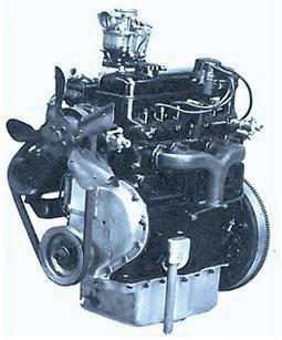
B range engines were manufactured in 3 main variants, 4, 6 and 8 in-line cylinders and subsequently two different bore diameters were available and identified by the engine code ‘0’ as 3.50in or ‘1’ as 3.75in. (B40; B60; B80; B61
and B81). All the engines had overhead inlet and side exhaust valves. Having been initiated at Clan Foundry, most of the design principles were in place prior to the transfer of the engineering department to Crewe in 1948. For cars, a third bore size of 3.625in (see previous page) was used and became known as the big-bore engine.
In 1943 W. A. Robotham returned to the Chassis Division at Clan Foundry where he arranged for the installation of a B80 in a tracked vehicle to become a Bren Gun carrier replacement. He successfully persuaded the Director of Fighting Vehicle Research that it would be beneficial to adopt a ‘rationalised series of engines’ with common
features across the range to minimise parts storage. This would be in line with the Company rationalisation policy that had been initiated by R.W. HarveyBailey. His report is attached at the end of this chapter, dated 6th April 1948. It provides power ratings and a breakdown and weight analysis of the B range engines of that era. The policy was largely successful for all the moving parts on the early military and commercial versions.
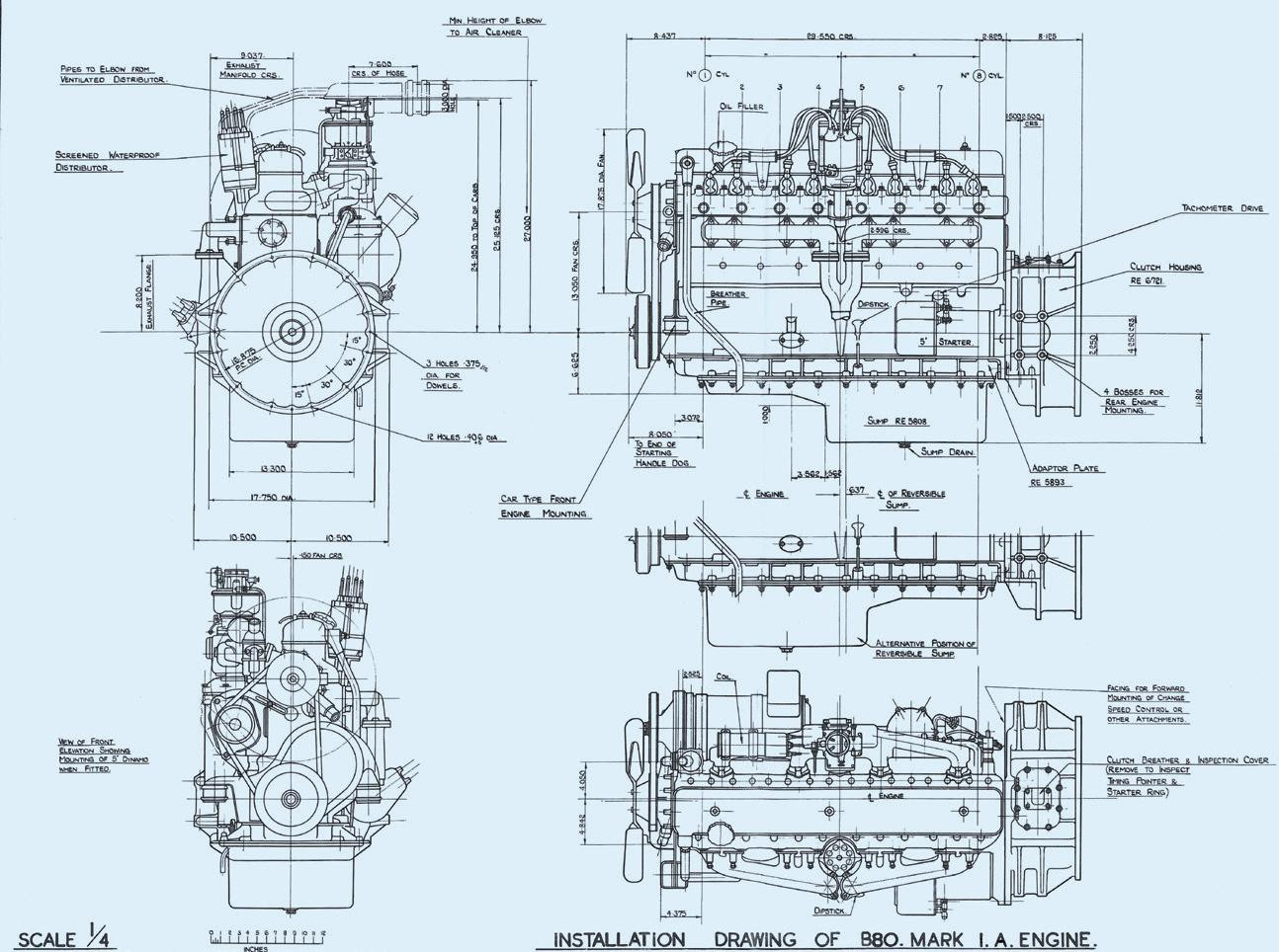
However, the multiplicity and variety of customer requirements always challenged the principle and the many external features and ‘engine dressing’ variants prevented total rationalisation. Even when the Engineering department was transferred to Crewe, one of the routine tasks was to continue producing and co-ordinating the catalogue of installation drawings for each of the engines, particularly to accommodate the large variety of versions required for the commercial market.
The ‘B’ range petrol engines were liquid cooled, naturally aspirated four stroke engines of conventional design with in-line cylinder arrangement and overhead inlet and side exhaust valves. They were usually supplied with coil ignition although magneto ignition was also available. The fuel was supplied by a diaphragm mechanical pump to one or more carburettors.
In order to meet the different operating and installation conditions the range included both wet and dry sump lubrication systems. A great variety of standard auxiliary units and drive arrangements were accommodated.
Many of the components were common to all versions in order to facilitate servicing and reduce the necessary spares stock holding.
Crankcase/Cylinder Block. The crankcase and cylinders consisted of a monobloc iron casting which, except for the B81 engines, were fitted with short, dry, Brichrome liners extending 2.50in down the bore. B81 engines were fitted with full length dry liners of high phosphorous cast iron. The crankcase carried both the main and camshaft bearing housings, being stiffened by deep
transverse webs and provided an intermediate main bearing between each throw of the crankshaft.
Crankshaft. This was a forging in chrome molybdenum steel which was nitride hardened. The balance weights were forged integrally with the shaft which was statically and dynamically balanced. At the front end, an externally mounted torsion damper was fitted that reduced the crankshaft oscillations over the full working range. Thrust was taken by steel backed special bronze washers, one on either side of the centre bearing.
The flywheel and starter ring assembly were bolted to the rear end of the crankshaft. Valve timing marks were stamped on the flywheel rim.
Connecting Rods. These were ‘H’ section steel forgings matched by weight and drilled longitudinally for pressure lubrication of the gudgeon pins, and splash lubrication of the cylinder walls via a small drilling on the side of each rod.
Bearings. The main and big end bearings were steel backed copper-leadindium shell type.
Pistons. The pistons were made of light aluminium alloy with fully floating gudgeon pins and except for those in the B 81 engines, were of the solid type with two compression rings and a slotted scraper ring. The pistons in B 81 engines had ‘T’ slot split-skirts, each with three compression rings and a flexible oil control ring.
Camshaft. The camshaft ran in steel backed white metal lined bushes. The lobes on the camshaft were off-set to the tappets to promote rotation of the tappets and thereby minimise ‘spot’ wear. The camshaft driving gear was bolted to the camshaft and was of aluminium or cast-iron depending on the engine specification. Provision was made for driving the petrol pump and a tachometer.
Tappets and Push Rods. The tappets were supported directly in the cylinder block and the push rods operated the inlet valves via the overhead rocker-gear, the exhaust valves being directly operated by the camshaft.
Valves and Valve Gear. Each cylinder breathed through one overhead inlet valve and a side exhaust valve. The inlet valves ran in cast iron guides fitted in the cylinder head. The exhaust valves had ‘stellite’ faces and stem tips and worked in phosphor bronze guides in the cylinder block. Exhaust valve seat inserts were fitted to B81 engines.
In addition, the exhaust valve heads on B81 engines were coated with ’Brightray’ metal to provide extra resistance to the build-up and corrosive effect of the combustion products, and the valve stems were fitted with rotators. The valve faces were machined at an angle of 45o and two springs retained each of the inlet valves on their seats, one heavier spring being fitted to each of the exhaust valves.
The inner and outer springs of the inlet valves were located by machined washers which ensured that the springs were concentric to each other and to the valve stems and prevented the springs from rubbing against each other. The spring pressure was applied to each of the inlet and exhaust valves via a pair of tapered collets that were located in the circular grooved retainer washer that also held the valve stem seal. The collets were applied by compressing the valve springs sufficiently to slide each collet down the valve stem and then releasing the pressure so that the collet was locked against the shoulder on the stem.
Cylinder Heads. The cylinder head was made of cast iron on military and commercial engines. A copper surfaced asbestos interlayer gasket was interposed between the cylinder head and the cylinder block. The ‘car version’ had an aluminium cylinder head.
Oil Sump. A choice of wet or dry sump was available. An adapter casting was fitted between the sump and the cylinder block to facilitate the fitting of various designs to suit the chassis. i.e., if the application/vehicle was for use on uneven ground, the dry sump made the engine suitable for working up to an angle of 40o from the vertical in any direction.
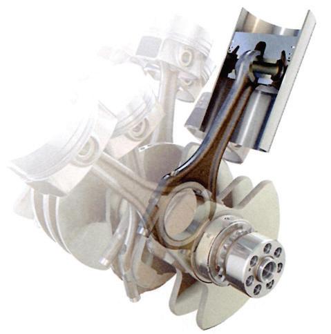
Oil Pump. The oil pump was driven at 1/2 engine speed. The lubrication system worked on a pressure feed, full-flow filtration system and used either a wet or dry sump; the main difference was the provision of an oil tank and the use of a scavenge pump on the dry sump system. In the wet sump arrangement, oil was drawn directly from the sump, but with a dry sump oil was supplied from and returned to the separate tank via the scavenge pump.
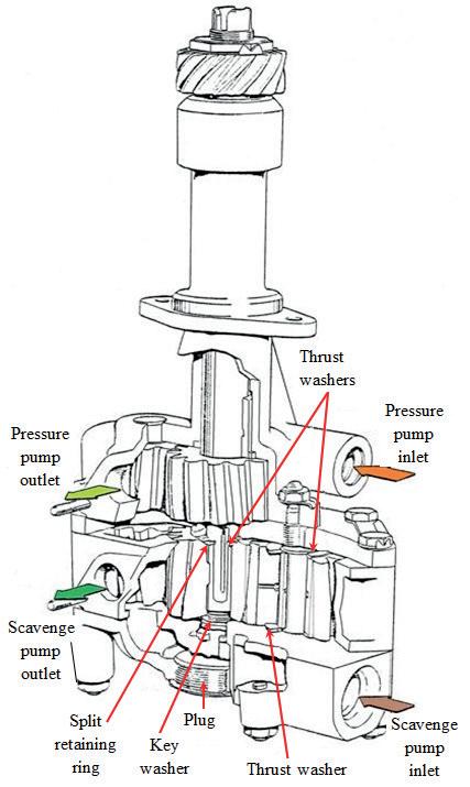
Oil Pump Assembly. The illustration shows both the scavenge pump for the dry sump condition (lower section) where the oil is returned to a separate tank via a cooling matrix. The upper pump draws oil from the remote oil tank, in the dry sump condition, or directly from the sump otherwise.
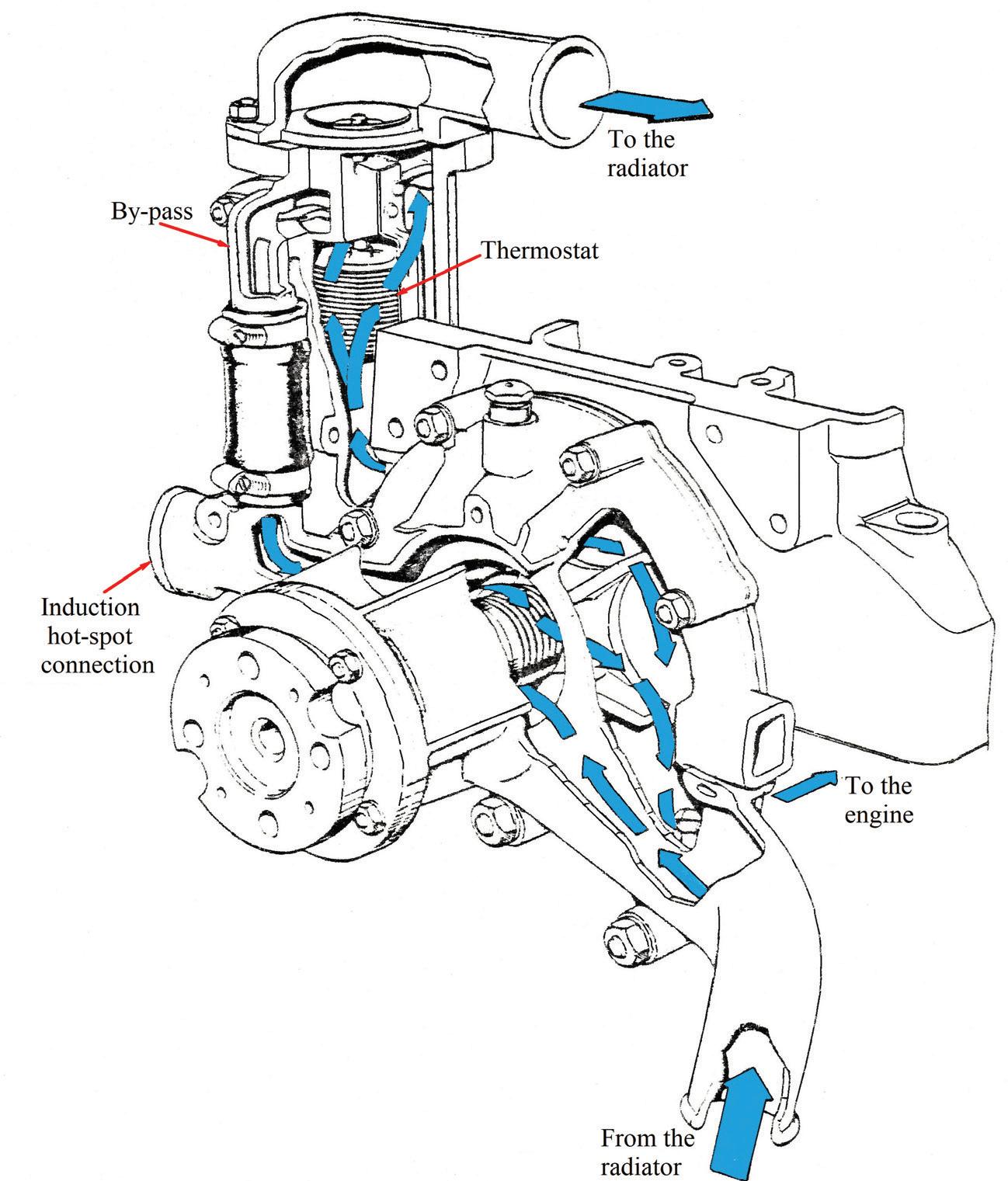
Cooling System. The system was either pressurised or not. For the former, it was controlled by a relief valve and the heat dissipated through a small radiator matrix. The coolant was circulated around the engine by a centrifugal pump and the temperature controlled by a thermostat mounted adjacent to the pump.
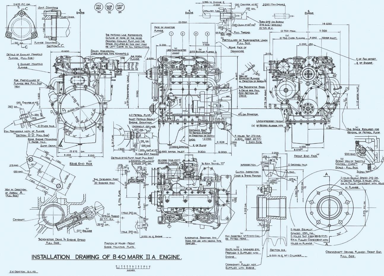
of installation drawing for a B40 Mk2.A Design RE 8156 (16/11/49)
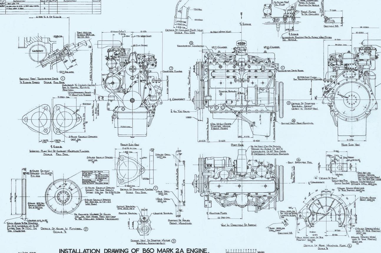
Part of installation drawing for a B60 Mk2.A Design RE 16004 (17/10/54)
As military vehicles evolved, requests for different features to suit the new installations and performance were received. A team of engineers was employed at Crewe to design and develop each version. These developments were complemented by extensive testing either on the engine test beds or using military vehicles. A heavily laden army wagon ran daily on endurance tests through the Peak district of Derbyshire for many years with different models of B80 and B81 engines. These vehicles were based in a special garage that had been commissioned as part of the Crewe test bed complex.
The all-cast iron military (and commercial) B range engines were nearly the same as those used for the cars. Car versions had aluminium cast cylinder heads and other, mainly external, aluminium features.
Most of the military engines were designed to be waterproof with sealed electrics and ignition systems which were also designed to minimise radio interference. They had the thermostat housing separately mounted whereas the car engines had the thermostat mounted directly in front of the cylinder head.
Many military B engines had adaptor plates between the crankcase and dry sumps to permit use at extreme angles. Wet sump variants also use the adaptor plate that allowed in-service changes from wet to dry sump to be made. The B60 & B80 had longer crankshafts with front mounted external torsional dampers. On later military versions (post Mk 4), a UNF logo was cast onto the rocker cover to denote the change from the traditional use of BSF, BSW and BA threads.
The car engines used the Rolls-Royce or Bentley logo even when they had adopted the UNF thread system. B range engines, with the adaptations to suit the cars, were fitted to all the Crewe built car ranges from Mk VI in 1946 through to 1959, when they were replaced by the V8 engine in the Rolls-Royce Silver Cloud II and the Bentley S2.
External torsional damper
Sump adaptor ‘plate’ used mainly with dry sump applications, though this is a wet sump engine.
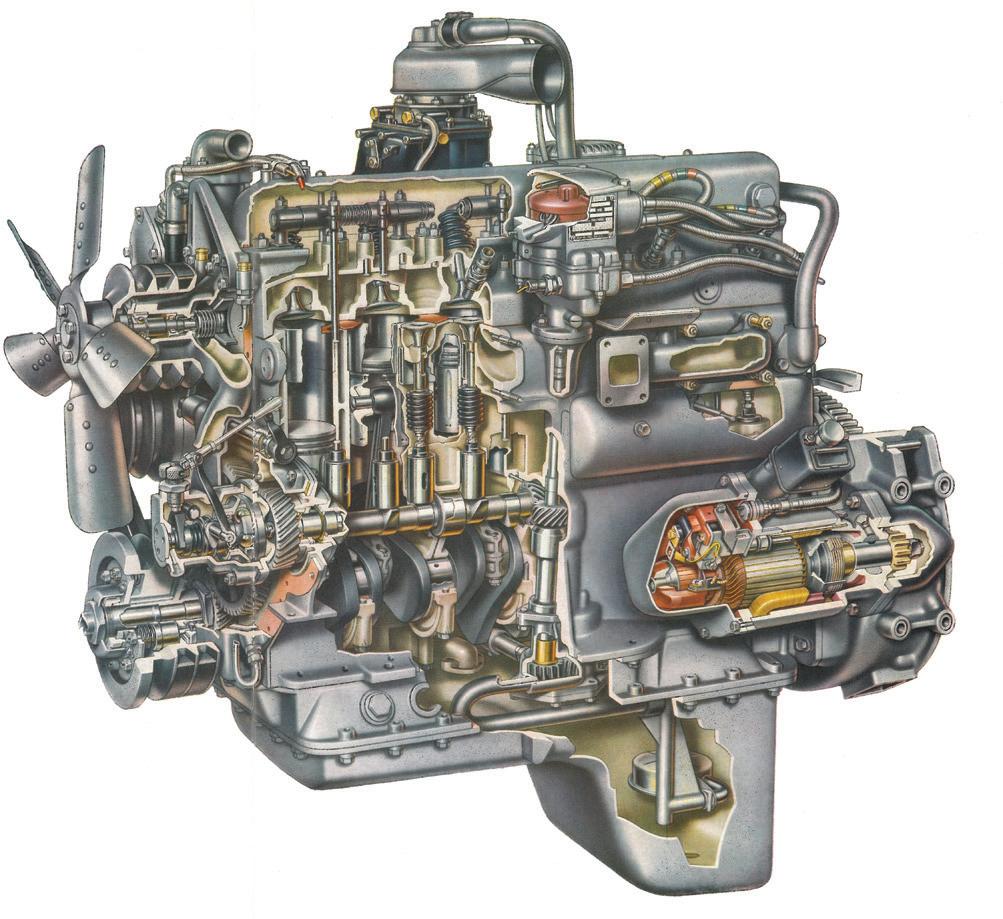
Collet/Valve spring retaining washer as used for both the inlet and exhaust valves.
Thermostat mounted integral with the cylinder head.
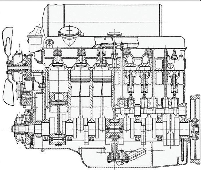
Exhaust valve size / diameter limited due to the design configuration with the valve’s seats cut into the cylinder block.
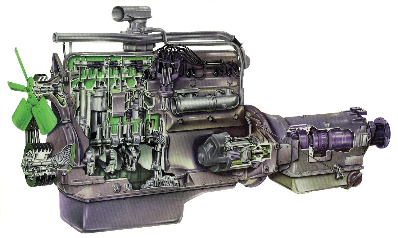
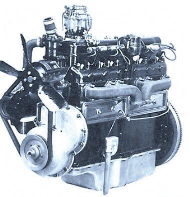
A Part Sectioned B 81 Engine for commercial use. Fitted with a GM automatic gearbox. This engine doesn’t have sealed electrics etc.
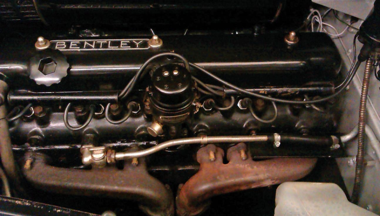
The 6 cylinder engine was used for both the Rolls-Royce and Bentley range of cars from early in 1946. It was subjected to a continual challenge for improvements that ranged from weight and cost reduction to increased capacity to meet the perpetual request for more power and thus provide the cars with improved performance.
However, the engine format of having the overhead inlet valves in the cylinder head with limited combustion chamber height that restricted gas flow and the exhaust valves within the main crankcase created fundamental challenges to improving performance without major capital and tooling investments. Hence it continued only until the introduction of the L engine with Silver Cloud II and Bentley S2 in 1959.
It was apparent that the power limitations were caused by the restrictions to exhaust gas flow within the combustion chamber and through the valves that could not be significantly increased in diameter without major modifications to the crankcase casting. Many ideas were tried, but only achieved limited increases in power.
These challenges had previously been faced in the early 1950s and had led to increases in the car engine capacity via a larger bore. This earlier work pioneered the similar solution for all the military and commercial B range that led to the B81 & B61 engines being introduced.
Numerous ideas to save weight were tried including an aluminium crankcase (including cylinder bore) and cylinder head to replace the ‘all cast iron’ parts. One such engine was fitted to an early post-war Bentley Mk VI car that was running with the experimental fleet, designated 3 B VI and had a ‘big’ bore (3 625in) engine. The car was used mainly as the personal transport for Engineering Director, Harry Grylls. This ‘aluminium engine’ ran successfully for a couple of years before the car was scrapped due to the requirement to keep the fleet up to date and test L engines before the introduction of the new Rolls-Royce Silver Cloud II and Bentley S2 series cars.
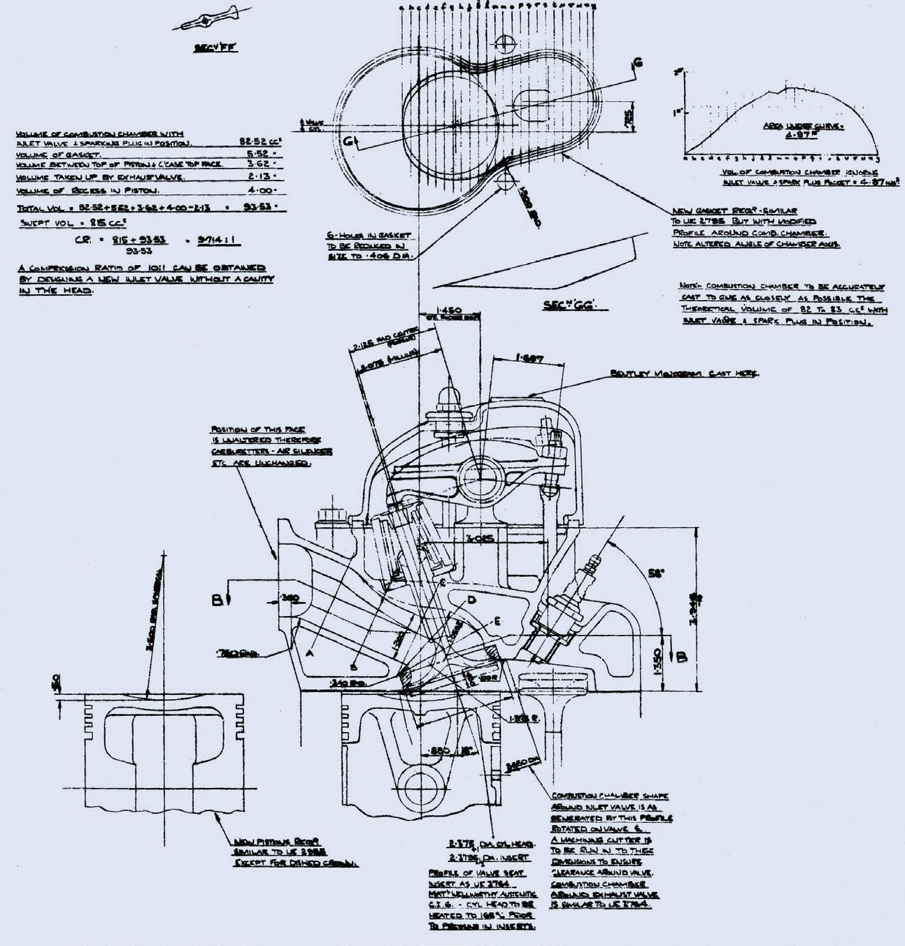
The introduction of the further increased capacity car engine (from 4 566 to 4 887 litres), and a decision to increase compression ratio to 7 25:1 now that improved leaded (anti-knock) fuels were becoming available, allowed
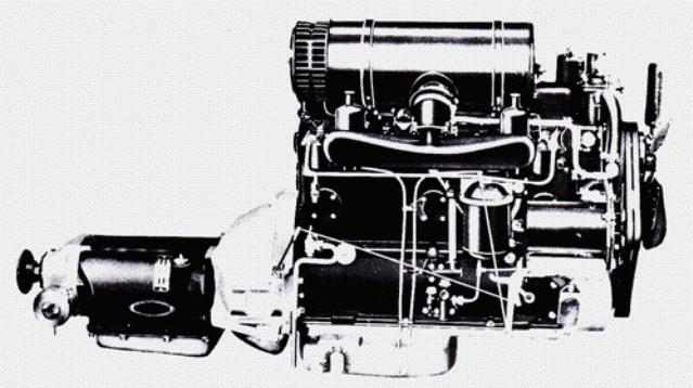
The Crewe designed S1 Engine and Gearbox, (circa 1956). 4.887 litre inline six. This new version of engine, not only increased the capacity, but also introduced a new induction system with twin SU carburettors.
four more years of production for the straight six car engines. This allowed further, highly necessary development and proving time and further mileage accumulation on the L engine that was essential following the decision to reduce its width (see Chapter 8).
In parallel there were many attempts to improve the car engine performance. Some proved beneficial, but some such as fitting a Solex carburettor were not
successful and even reduced power that would have lowered the top speed by some 10 mph.
One innovative idea in 1957 was to try the Lucas mechanical petrol ‘shuttle valve’ injection system to replace the carburettors. This work was directly linked to the efforts to make multi-fuel versions of all the military engines. Several B range engines were made and tested. A B81 version was fitted to the Dennis Max Tractor as one of the Company transport vehicles.
Similarly, several car engines were made, and one was fitted to the early S series prototype car, 22B. This also used a Lucas mechanical fuel pump and injector system. Despite concerns about its potential reliability, lack of altitude compensation and poor refinement particularly at idle speeds, the engine ran for several years and gave few problems. Its power output was only slightly lower than the early ‘wide-head’ L engine that was fitted to the experimental
car 21B in 1957 and side-by-side vehicle performance checks showed that 21B was less than 1 second quicker in a 0-60mph acceleration test. Nevertheless, at the higher speed-range performance of 21B was perceptibly better than that of 22B.
From 1946 until the launch of S, Series in 1955, 7,266 Bentley Mk VI, and Rolls-Royce Silver Dawn and associated cars were manufactured all using the car version of the B Range six-cylinder engine.
When measured to DIN standards, running at 4000rpm, the Mk VI, 4.257 litre engine produced 133bhp. The Silver Dawn/R Type 4.566 litre engine produced 135bhp. The S1 4.877 litre engine produced 153bhp and the late R Type Continental 4.877 litre engine produced 164bhp.
In the early to mid-1950s a large development programme was undertaken and led by Neville Daniel.
1. To improve the life expectancy of the exhaust valves. Tetra Ethyl lead (TEL) had been launched as an anti-knock agent (3.6cc of TEL per gallon).
This programme and the expertise gained, pioneered the subsequent designs and specifications for the valves and their seating materials for the later B range of engines, F, G and L engines. Initially the B range engine had exhaust valves made of Kaiser Ellison (KE) 965 steel with ‘stellite’ faces. The inlet valves were S65 steel. Both valves had seats cut directly in the cast iron crankcase or cylinder head respectively. The car engines had S65 inlet valve seat inserts in the aluminium cylinder head.
The test schedules used were, initially, a) continuous running at 3,750rpm full throttle until failure, and b) a cyclic test that followed the practice used for the development of a new engine.
The former produced fatigue failures in the valve head in the form of circumferential cracks between the valve rims and their stems. However, the cycling tests operating between mild and high duty loads produced other challenges.
Firstly, during the more moderate periods, lead compounds would build up on the crowns of the exhaust valves that would become active at the higher temperatures of higher load cycles and attack the valve crown material, producing an incandescent active crust that instigated pre-ignition. This resulted in even higher combustion temperatures and pressures that caused even higher material temperatures. These triggered splits in the exhaust valve rim and caused the inlet valve heads to stretch so that the "tulip" shape became more of a straight cone. In this condition the valve seated on the line contact of the inner edge of the seating face and bored its way into the cast iron head seating. Pre-ignition could also burn holes in piston crowns if it lasted long enough.
The cyclic test also created expansion and contraction of the combustion chamber, the floor of which was the top face of the crankcase and cylinders that also contained the exhaust valve seats. These were mounted very close to the edge of the cylinder bore. Hence, at maximum output, the local temperature in this narrow bridge was high enough to cause the material to yield in compression so that, at lower duty, the then cooler material contracted and generated a tensile stress in the valve seat adjacent to the cylinder. As a result, continuing cycles produced a fatigue crack in this area.
During the programme sodium cooled exhaust valves were tested and, despite running cooler than the standard ones, there was insufficient valve guide cooling to carry away the increased heat in the valve stem with the result that carbonised oil caused them to stick – so this approach was abandoned.
Whilst conducting these tests, many measurements had to be taken directly from the engines which meant that Neville Daniel and members of his team were subjected to the heat, exhaust gas fumes and extreme noise from the engines when running at full throttle with open exhaust. Obviously, this practice would not be acceptable today!
The problems were resolved by applying a Brightray coating on the exhaust valve crown, as Merlin engine practice, that resisted the lead compound attack, and introducing austenitic iron inserts for the exhaust valve seats to withstand the high temperature compressive stresses. These measures were carried over to the B range, F and L engines. Due to the absence of pre-ignition, the inlet valve temperature was low enough for the cast iron B range inlet valve seats to be adequate for any duty that the car might have to endure. The B engines used in cars, G, F and L engines already had to use valve seat inserts with their aluminium main structure.
2. Multigrade oils. In about 1950, ‘Multigrade’ oils were initially marketed to avoid the traditional ‘twice each year change of oil’ needed with the ‘summer and winter’ grades. These were not yet approved by the Company, but a few customers used them and quite quickly the Service department were reporting engine problems, particularly tappet wear. Tests showed that these new oil specifications did not provide the protection that was required. This prompted intensive collaboration between the Crewe engineers, Laboratory staff and the oil companies. Only when the ‘anti-scuffing agent’, Zinc Diothiophosphate (ZDP), was added to the original formulation of these oils were they useable. These problems led to regular 250hr endurance tests for production engines particularly when any new oil was advertised.
3. Tappet life improvement. Experience and testing had shown that the life of the tappets, that were to an original Charles Jenner design, was less than was expected. They could fail by a process of exfoliation of material from the chilled iron base that would cause wear on the cam peak. The problem was traced to a flaw in the design where the cam lobes were bevelled making them narrower than the base circle so that the offset of the contact area caused the tappet to rotate and avoid the formation of a groove in the base that could cause noise. However, since perfect alignment can never be achieved due to machining tolerances/inaccuracies, the tappet could be subjected to very high stresses by the edge of the cam peak. In extreme cases excessive stresses occurred at full lift and low speed, causing compressive fatigue cracks that permitted oil, under hydrodynamic pressure, to spread beneath the surface and eject material.
The cure was to leave the cam width constant all the way round the lobe and grind a 150in spherical radius (much larger than that used on the later L engine) on the base of the tappet that eliminated the edge loading. The desired, and beneficial, tappet rotation was achieved by grinding the cam with a 0º 5-7’ axial taper that offset the contact patch sufficiently. This system was successfully introduced for the B range engines and the adaptations used in cars.
By the 1960s, the MoD had fully adopted a multi-fuel or diesel engine policy
Significant items of information used in this chapter were taken from the VW presentation at an engineering symposium in Vienna in 2015. The authors are accredited in the list of contributors in the Preface.
As mentioned in Chapter 14, the W12 engine started in the early 1990s with a concept 5.6 litre version shown at the Japanese motor show in 1997. This was quickly followed by the 6.0 litre, non-turbocharged, multi-point-port injection version that delivered 309kW with a maximum of 550Nm torque. This was introduced to production in 2002 in the VW Phaeton. A year later the Biturbo (Twin Turbos) version was created by Bentley and Volkswagen engineers for
the Bentley Continental range of cars. This produced 412kW and had a maximum torque of 650Nm. Several developments followed with the latest version achieving 471kW (640bhp) and a peak torque of 800Nm. These figures supersede the information in the table below.
By 2011, the engineers both at Crewe and VW had gained a great deal of experience with the W12 TMPI (Turbo-charged, Multi Point Injection) engine that had now been running for nine years in the Bentley Company’s GT range as well as naturally aspirated versions (including the 6.31 litre Direct Injection variant) in several other VW Group cars. Jointly, they were very confident about the general format and layout of the engine where its overall length and mass were a major benefit to the vehicles weight distribution that helped with comfort and handling and where its shortness gave the designers opportunities to create superb exterior styles without intrusion into the saloon. This combined with careful design for body structure collapse during a frontal crash is a major benefit to ‘occupant safety’ that is increasingly important. Similarly, the overall height of the engine is kept to a minimum to ensure compliance with the pedestrian head impact criteria, particularly on the Bentley GT range where good aerodynamics is imperative. Both these safety aspects are becoming more challenging as worldwide legislation becomes more severe.

of the Design ‘Concept Proposals’.
The engineers and management were therefore faced with the dilemma of how to introduce a whole range of desirable engine upgrades and developments that were becoming available to improve the performance and efficiency as well as implement production manufacturing enhancements in the most expedient manner.
It should be remembered that any one of these elements that imposed significant change to a major component or system, if introduced individually, would have required its own development, endurance testing and certification approval prior to investment in production tooling and launch. Hence it was decided to collect all the ideas and produce a design for a completely new engine that retained the W12 layout. So, the W12 TSI concept was conceived.
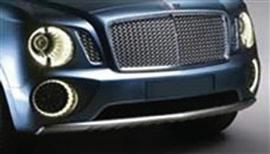
The W12 TSI was launched with the new Bentley ‘SUV’ vehicle Bentayga in 2016.
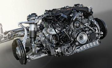
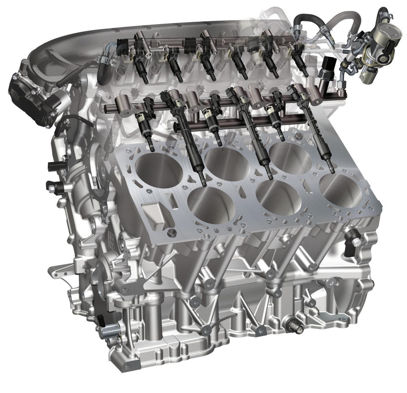
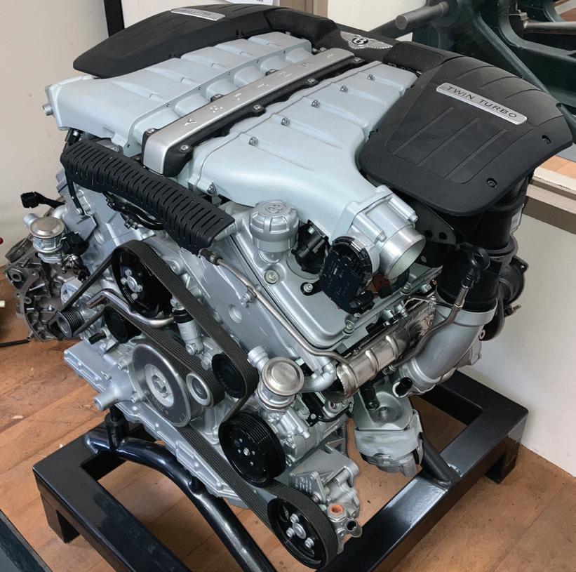
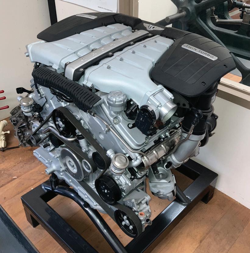
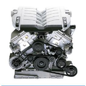
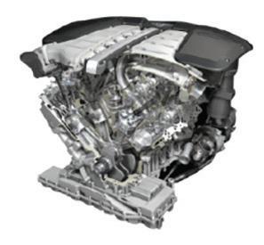
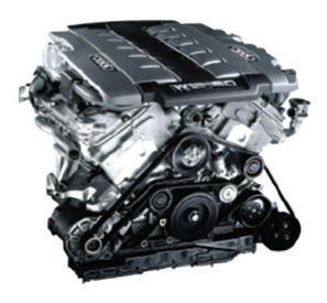
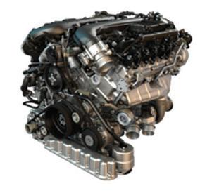
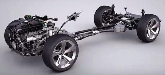
A View of the W12 TSI Engine and front suspension as viewed from the 3/4 front. This view shows the extremely efficient packaging of the engine and front suspension assembly
Jon Dewey, Mark Frost, Terry Croft, Paul Taylor, Steve Burdett, Tom Fielding, Phil Hedley, plus many more across the Bentley associated engineering and test/certification functions.
• The base engine to have improved performance and response.
• The engine design to provide integration of cylinder deactivation.
• Optimise the transient characteristics with the adoption of Twin-Scroll Turbochargers.
• Ensure that the oil/lubrication system is proven for increased angular positioning of the engine during off-road use.
• Provide a major reduction in CO2 emissions/improvement in fuel economy.
• Optimise the major structures to ensure minimum weight whilst achieving VW Group standards of strength and durability.
Alongside a core group of VW engineers, the following Crewe based engineers were part of the overall team that was responsible for the launch of the new W12 TSI engine.
Paul Williams, Nico Gerhardt, Ian Malpas, Simon Baron-Oxberry, Paul Fish,
• Design the combustion process for the dual injection system and integrated thermal management to ensure compliance with the emission levels that are specified in New Euro 6 phase 2, (New European Driving Cycle) and the ULEV 125 category. (Ultra-low Emission Vehicle) as implemented by the California Air Resource Board.
• Optimised crankcase structure.
• Cylinder bores with Atmospheric Plasma Spray (APS) surface coating.
• Crank-train assembly with induction hardening for the forged crankshaft and new bearing shell assemblies.
• Lubrication system with a controlled variable performance oil pump. (Both pressure and delivery.)
• Integrated thermal management system for the engine temperature control.
• Cylinder de-activation of one-cylinder bank.
• Dual fuel Injection system.
• Biturbo of the twin-scroll type.
• Two separate, but linked engine management control units.
• Adaptive engine mounts for noise and vibration isolation i.e. comfort provision.
• Auto Stop/Start facility.
• New twin belt ancillary drive system.
• Improved deliverable performance.
With these ideas integrated in the new W12 TSI engine, they make it the most economical twelve-cylinder engine in the high quality/premier segment of the market. The CO2 emissions are extremely low, putting it in the ULEV (Ultra Low Emission Vehicle) 125 category. When these are linked with a power output of 447kW (600bhp) and a torque of 900Nm, they provide an impressive demonstration of the engine’s high efficiency. The power output enables the Bentayga to accelerate from zero to 100kph in 4 seconds and have a top speed in excess of 300kph. The engine runs incredibly smoothly under all conditions and the adaptive engine mounts ensure that engine noise is isolated from the body structure and saloon.
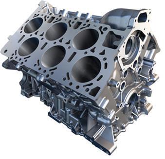
The crankcase followed its W12 TMPI predecessor by being manufactured from pressure die-cast hypereutectic aluminium and is designed as a shortskirt block with bed plate. The design is optimised with the bearing seats cast into the bed-plate structure whilst in the mould tool.
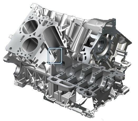
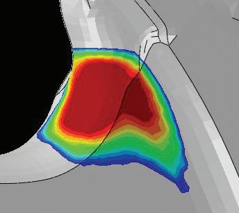
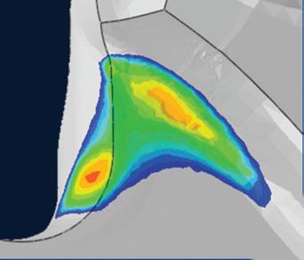
However, the drive to generate the most weight efficient structure whilst meeting all the other design parameters inevitably dictated that extremely careful structural analysis was needed to ensure that there were no areas that had been overstressed and could have led to premature failure. Hence all elements of the structural and weight optimisation were subjected to lengthy predictive stress analysis that was followed by practical testing. This programme is typified by the diagram below that shows just one of the areas under test and then revision.
A Top View CAD illustration of the W12 TSI Crankcase
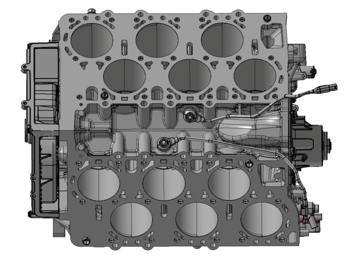
A Sectioned View of a W12 TSI Crankcase showing in detail just one of the areas optimised during the stress analysis.
Cylinder Bore Surface APS coating
Crank-train assembly with induction hardening for the forged crankshaft and new bearing bush / shell assemblies.
The cylinder bore surfaces are coated with a low-alloy steel coating to reduce friction and improve corrosion resistance when running in poor-quality fuel markets. Following a laser preparation process, the powder is applied using atmospheric plasma spray (APS).
3. Crank-train assembly with induction hardening for the forged crankshaft and new bearing bush / shell assemblies
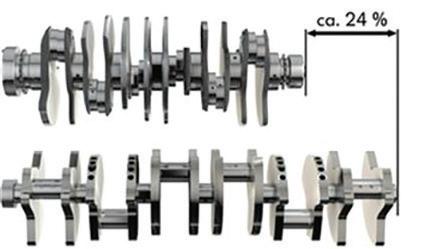
This length of crankshaft obviously is fundamental to the short engine length and provides all the safety and vehicle balance benefits as described in chapter 13 for the earlier W12 TMPI engine.
The forged crankshaft is induction hardened to ensure the required strength and wear resistance. The short length of the W12 engine, requires the bearing bushes and con-rods to be extremely narrow.
The forged steel con-rods have a ‘fracture-split’ design. This technique had already been successfully introduced to the Crewe engineers with 4.0 litre V8 engine that had now also achieved significant service experience. (The manufacturing technique is described in Chapter 15) However this was the first Crewe built engine to adopt the process.
The rods are forged as a complete unit with the bearing cap included. They have notches cut on either side of the horizontal diameter of the ‘big-end’ that create a weak section. Both the little and big ends are bored and then a splitting load is applied along the axis of the rod to separate the rod from the bearing cap. The forging breaks/fractures at the weakening notches leaving the surfaces quite rough.
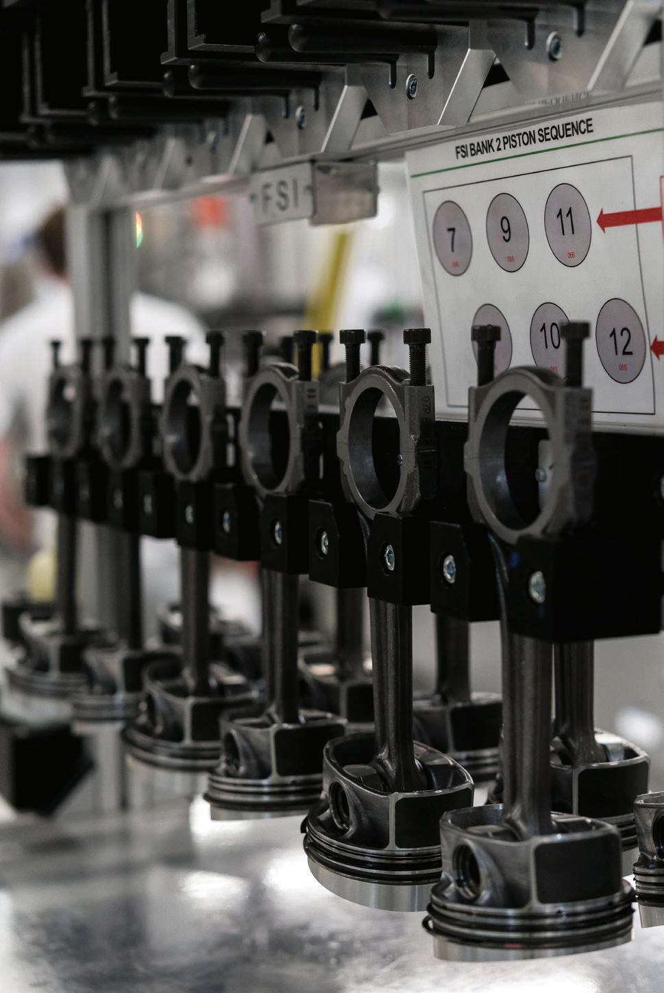
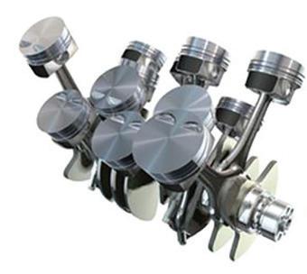
A set of No 2 bank piston and con-rod assemblies awaiting assembly to the crankcase. Note the chart on the wall behind showing the assembly sequence.
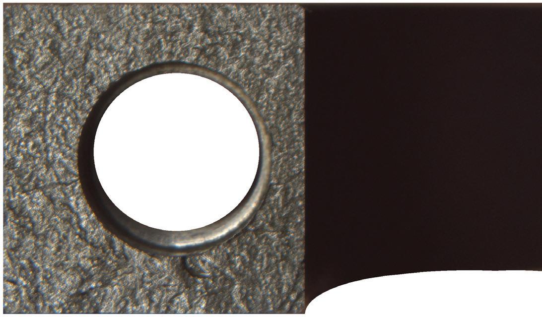

A magnified view of the rough surface of the bearing cap, with an exactly mating form on the now separated rod.
When the bearing cap is lightly re-positioned, the rod naturally finds its mating location. Its fit is so good that the split line is barely perceptible on either the external or bearing surface of the assembled unit.
This process avoids the traditional need when rods and caps are separately forged, for extremely accurate machining of the split surfaces and the very fine tolerance between the attachment bolts and their reamed holes in the bearing caps.
The hydrodynamic bearing pressures, even at maximum torque have been catered for in the new designs.
New bearing bushes for the W12 TSI combine a substructure made from steel and bronze.
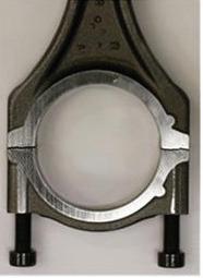
General view of the ‘big-end’ fracture-split line prior to the cap being tightened onto the con-rod
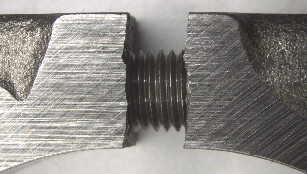
Magnified view of the ‘big-end’ fracture-split line. Note the mating contours of the fracture
This substructure and a high-strength wearing surface ensure good heat dissipation and facilitate the engine’s start/stop functionality.
Precision fine-tuning of the bearing bushes and conrods resulted in very good pressure distribution. The focus during this process
was on factors such as materials, surface qualities, crowning and pre-tensioning.
The oil supply bores permit extremely high wear limits in all relevant operating modes; radionuclide technology (RNT) analysis was conducted and used in correlation with oil pressure and temperature measurements at the bearing journals.
4. Lubrication System - with controlled variable performance oil pump for both pressure and flow
It was realised at the start of the SUV concept programme for the Bentley Bentayga, that the W12 TMPI lubrication system was not designed for a vehicle that was subjected to high pitch and roll angles. Hence a totally new system had to be evolved.
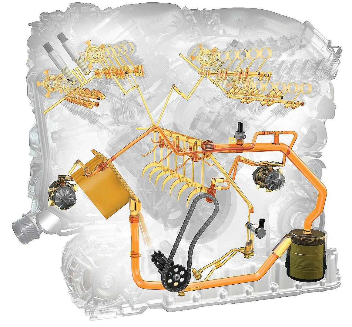
of the Oil Supply System for the Turbochargers that permits 35o vehicle tilt capability irrespective of its travel direction and acceleration or deceleration.
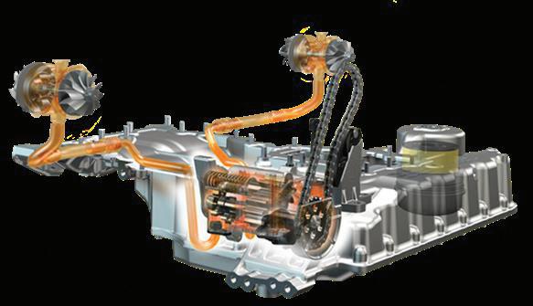
The W12 TSI is conceived as a wet-sump engine. Depending on the vehicle model, its oil supply handles the demands of off-road use as well as those of a sporty on-road driving style with high centrifugal forces of more than 1g. The oil pump is driven via chain from the crankshaft. The shape of the oil sump ensures continuous oil supply at extreme angles of up to 45o, thus ensuring 35o tilt of the vehicle over a full 360 degrees of travel and variable acceleration/ deceleration loads. The oil level is monitored by an oil-level sensor.
The two turbochargers are coupled to the two-phase switchable oil pump with separate oil suction stage. To ensure no oil can escape from the turbocharger bearing housings into the intake and exhaust tracts and to guarantee the function of the shaft seal ring when the turbocharger is stationary. This occurs when the second cylinder bank of the W12 TSI is deactivated.
The oil system was tested under extreme conditions including high ‘G’ forces thus being more severe than those imposed by the tilting test bed that was used for Military Engine approval (See Chapter 7.3 page 6). These tests were complemented with extensive off-road testing.
The thermal management of the W12 TSI shortens the warm-up phase after cold start and specifically channels the heat generated by the engine to the relevant areas. The cylinder heads are warmed up as fast as possible in order to bring the combustion chambers to optimum operating temperature quickly and ensure good, efficient combustion and reduce internal engine friction. However, conflicting with this is the challenge to provide comfortable temperatures inside the passenger compartment which presents an additional aspect in the optimisation of heat distribution.
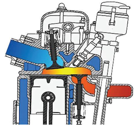
The design principle of the W12 engine further aids rapid warm-up of the cooling water. Incorporated into the cylinder heads are the long exhaust ports of the three inner cylinders that have an effect similar to the use of a partially integrated exhaust manifold.
To control the separate heat distribution requirements, the overall cooling circuit comprises three sub-circuits:
• Heating circuit (red) incorporates cylinder head, heating system heat exchanger and an electrical water pump.
• Main water circuit (blue) comprising crankcase, engine oil cooler, a thermostat designed as a 2-way valve, the main radiator block and a mechanically driven water pump that can be pneumatically deactivated.
• Turbocharger circuit (green) with a separate, electrically driven water pump.
A separate heating and cooling circuit can be incorporated for the transmission if need be.
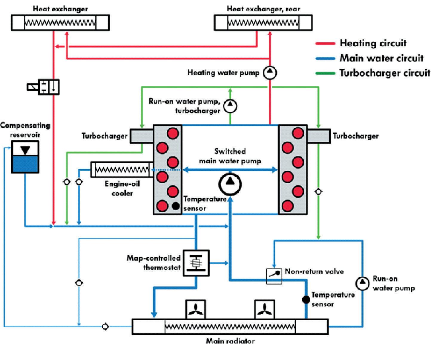
It was recognised that by providing the turbochargers and the vehicle air conditioning heater systems with their own coolant pumps that are separate from the main engine cooling system enabled them to be operated independently. The fast-reacting coolant temperature sensor was moved to the cylinder head, adjacent to the combustion chambers.
The switchable main water pump is a key element, using a pneumatic valve to block the water flow from the pump to the crankcase. When the valve is deactivated, a return spring restores the sliding valve to its starting position, releasing the flow (fail-safe function).
The low volume ‘air-to-air’ charge-air cooling system contributes to the engine’s excellent response characteristics. The two coolers are positioned on either side and behind the vehicle’s front skirt. The volume of air between the compressor outlet and the throttle flap is minimised by positioning the turbochargers on
the outside of the cylinder heads. The location of the two throttle flaps in front of the engine enables the very short pressure hoses to accommodate movement between the intercoolers which are fixed to the body shell and the throttle flaps fixed to the engine.
Overall, the new W12 TSI cooling system provides significant benefits to the engine and vehicle: -
• Reduced frictional loading / losses
• Improved engine warm up that reduces CO2 emissions.
• Improved vehicle interior heating in cold climates
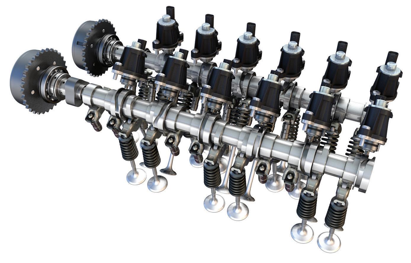
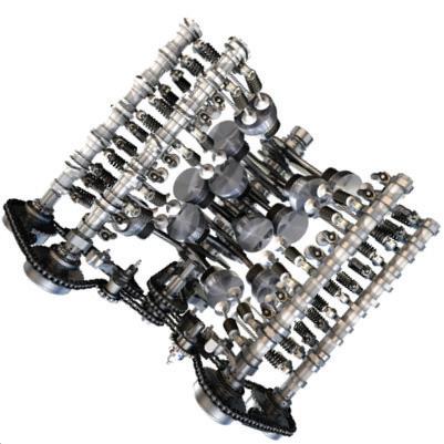
Valve drive system with ACT compact cylinder de-activation
The new compact Automatic Cylinder Management (ACT) cylinder deactivation system disengages all six cylinders of the left bank (bank 2) under moderate load and engine speed by closing the intake and exhaust valves and switching off injection and ignition. Prior to closing the valves, the combustion chambers are filled with a fresh charge. When half of the engine is running, the shift in operating point leads to increased efficiency and the W12 functions in principle as a Volkswagen VR6 engine with an ignition sequence of 1-5-3-6-24. Cylinder deactivation is possible in gears three to eight, at engine speeds of up to 3,000rpm and up to a maximum torque of 300Nm.
In the Volkswagen Group’s already proven valve control system, all switching is provided via cams mounted on sections of the hollow camshaft (see above). Electromagnetically actuated pins engage with grooves on the outside of the sliding cams and push them axially along splines on the camshafts. When the cylinders are deactivated, a so-called zero-lift cam with a 360-degree base circle rotates over the rocker arms.
In the development of the W12 TSI, the challenge was to adapt the existing Group De-activation system to the packaging conditions for W12 layout. The cylinder spacing in the W12 concept is 65.0mm and the valve spacing 36.5mm. However, the existing Group solutions with their assembly lengths of 76.0mm and 68.6mm and two actuators – either two single-pin actuators that engage in two s-shaped groove geometries or one dual-pin actuator running in a y-shaped groove geometry – were therefore not suitable for the W12 TSI. Hence the decision was taken to use one single-pin actuator and ‘a double S
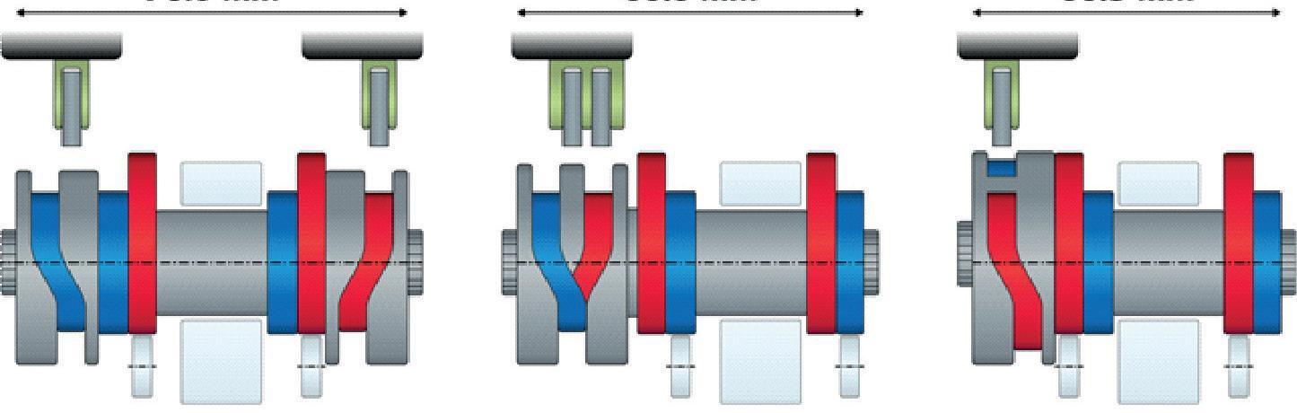
groove’ geometry, where the grooves for engaging and disengaging the cams are machined into a single disc at the end of the cam section.
The cam sections of the ACT compact deactivation system are just 63.5mm long, around 20 percent less than in the standard Group System. Furthermore, the new system switches are considerably faster: The area in which the pin engages is limited to just 50 degrees of cam angle (instead of 175 degrees) and the sliding takes place within 72 degrees (instead of 200 degrees).
Spring-assisted deployment of the pin increases the actuator’s performance. The pin’s travel time is only three milliseconds.