BSc Architecture
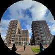
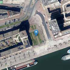
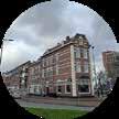
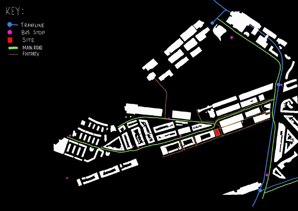
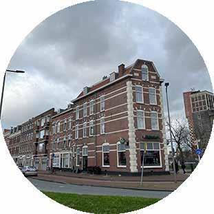
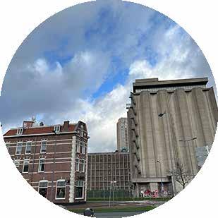
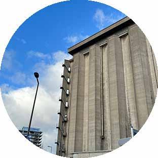
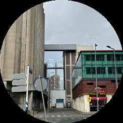
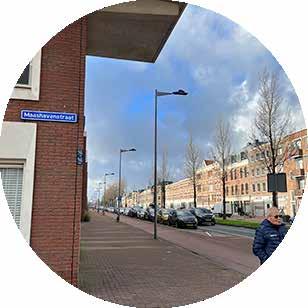
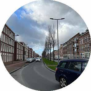
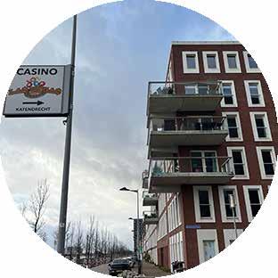
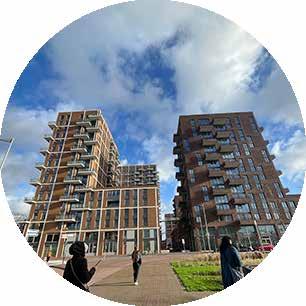
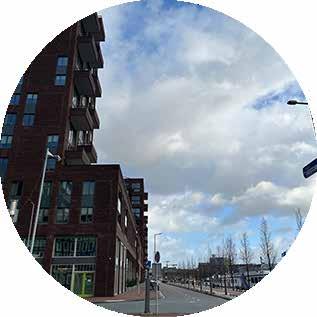
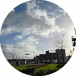
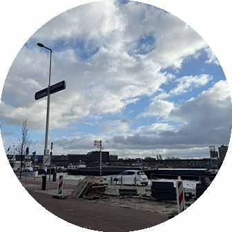
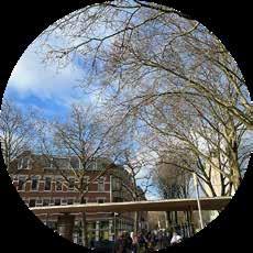
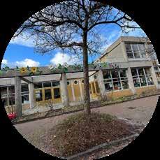
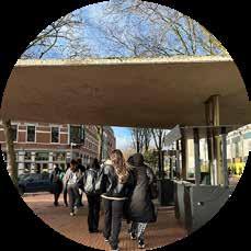
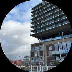
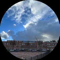
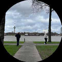
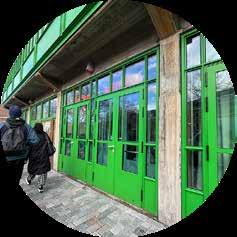
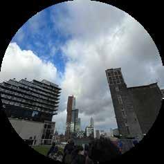
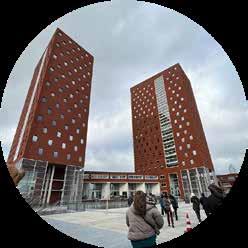
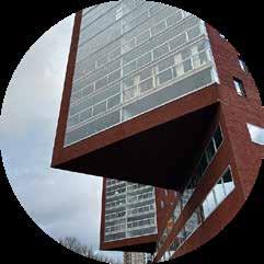
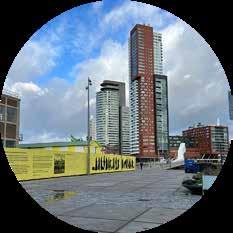
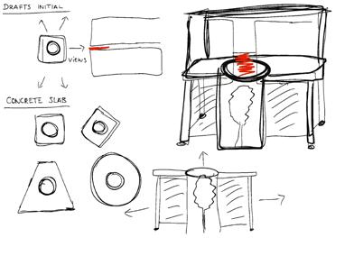
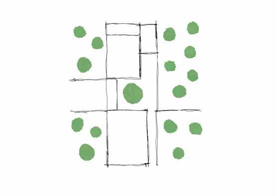
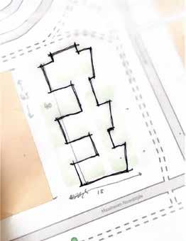
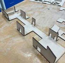
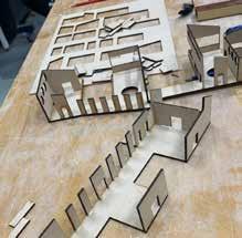
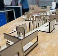
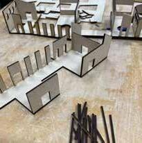
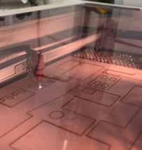
SITE VISIT


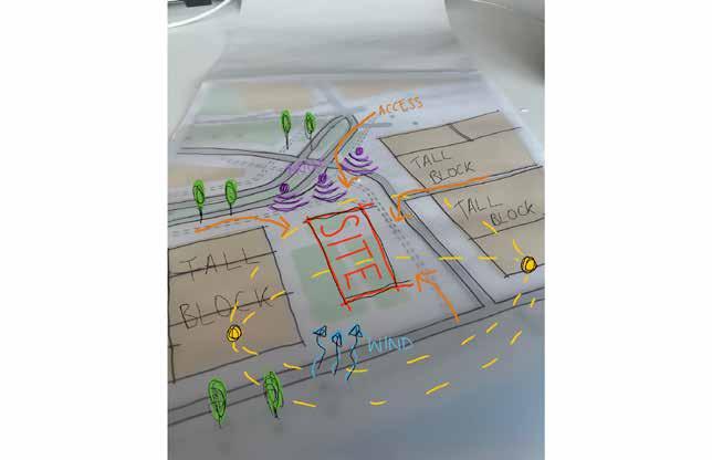
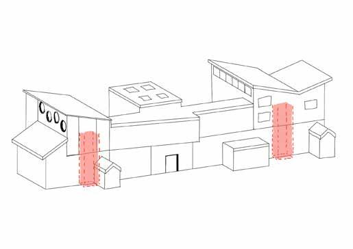
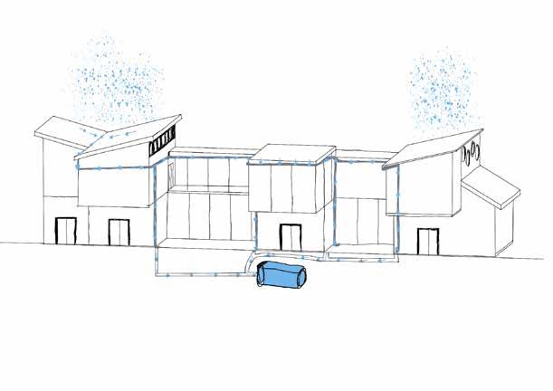
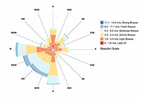
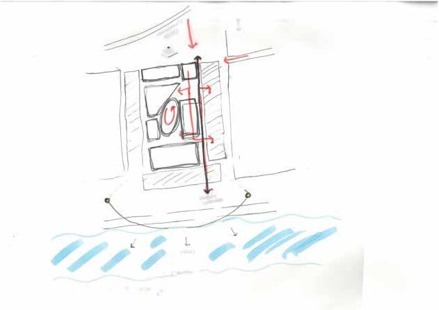
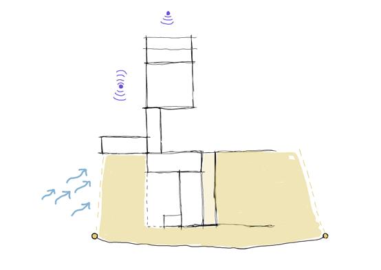
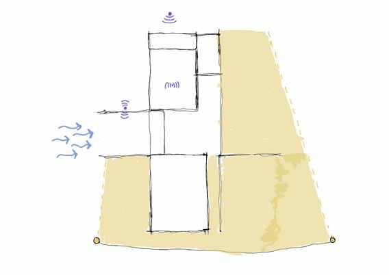
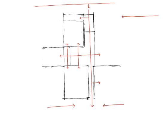
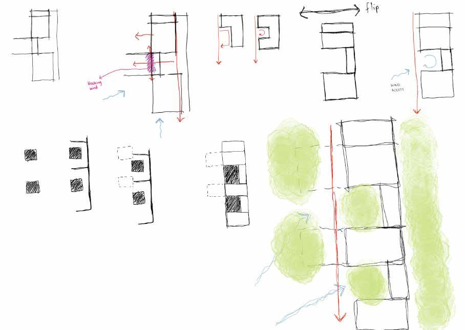
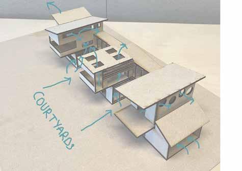
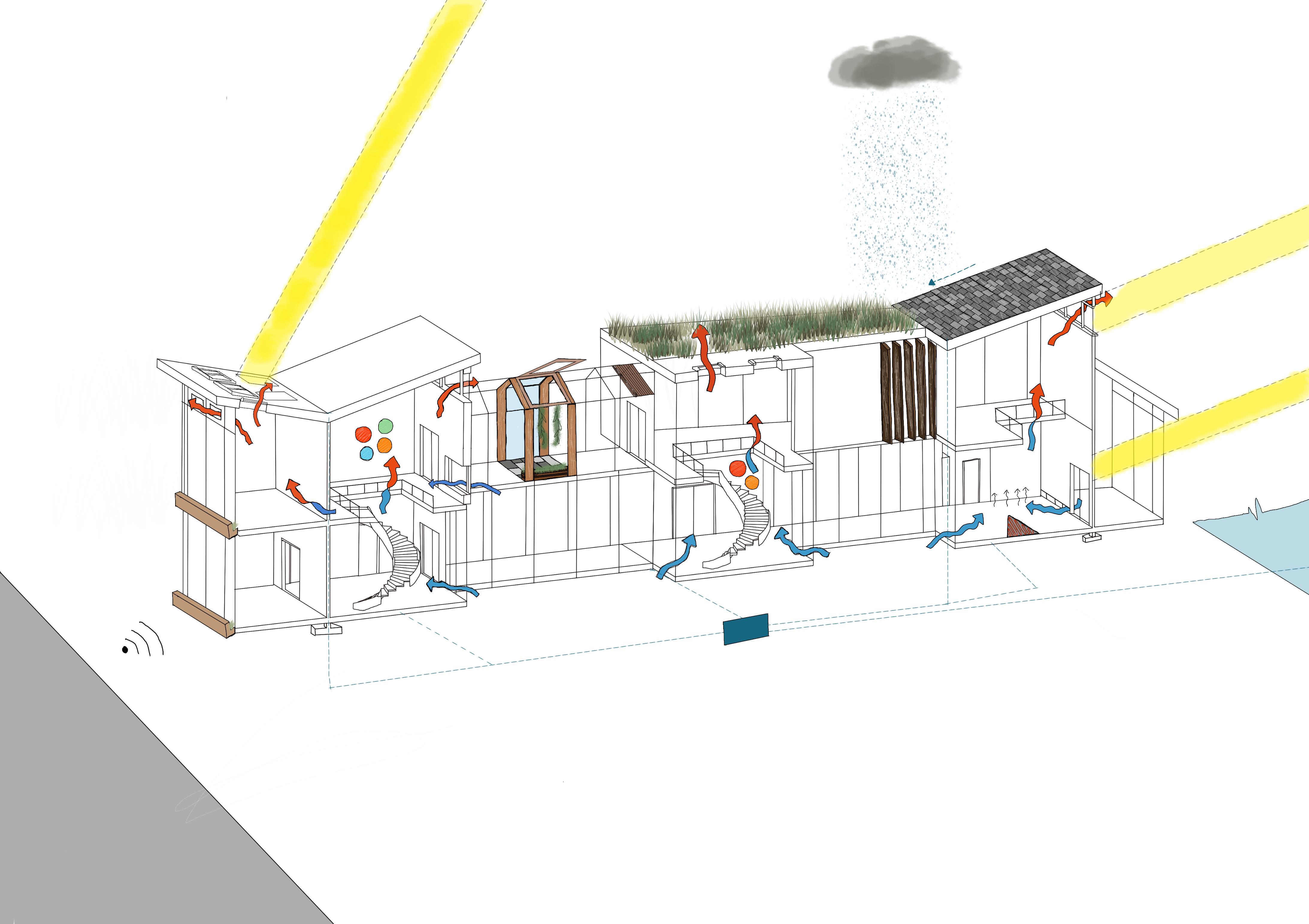
WIND ANALYSIS
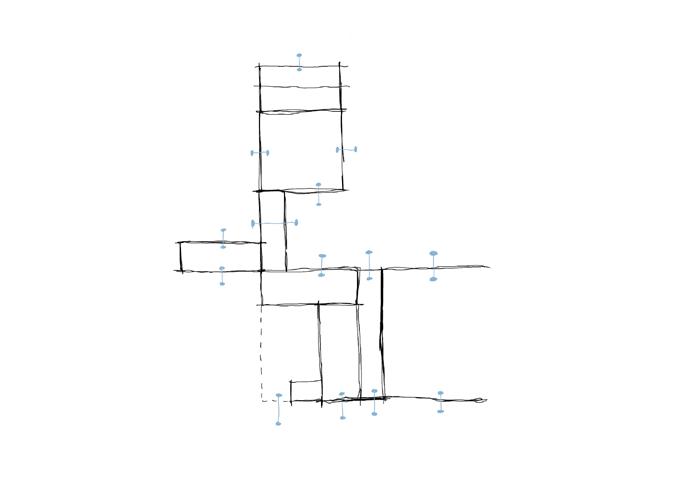
NOISE POLLUTION
VIEWS IN


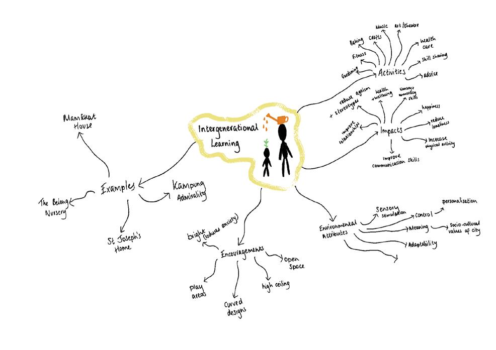
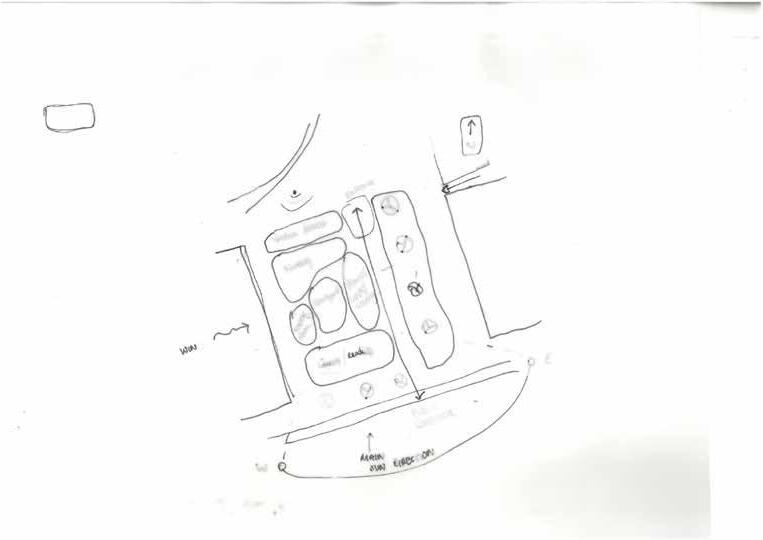
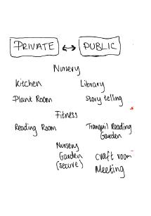
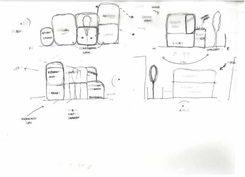
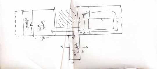
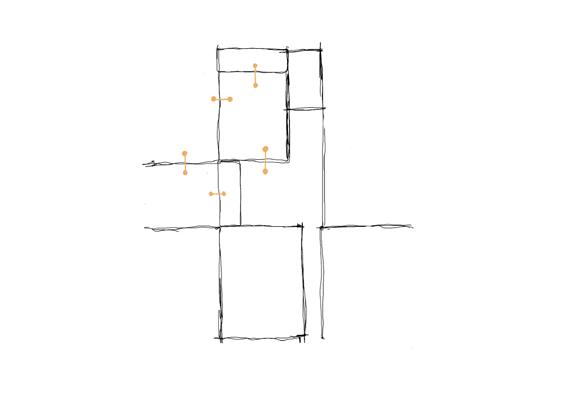
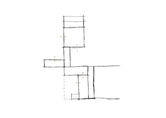
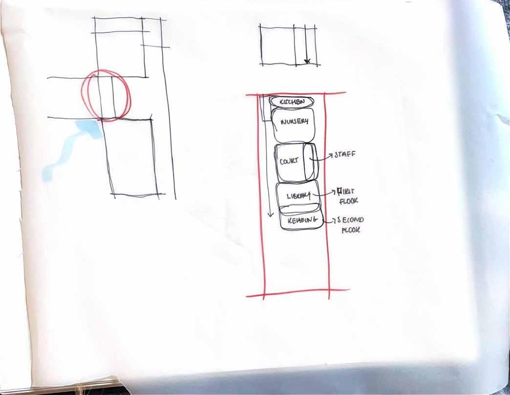
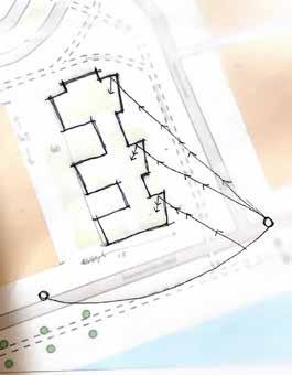
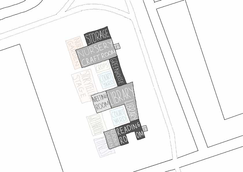
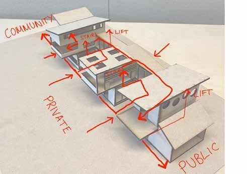
Intergenerational Links
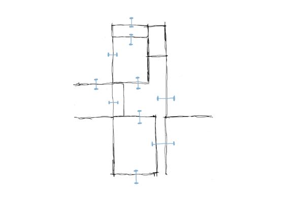
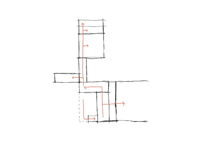
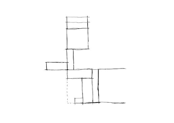
Access Points
Views
Intergenerational Links
Access Points
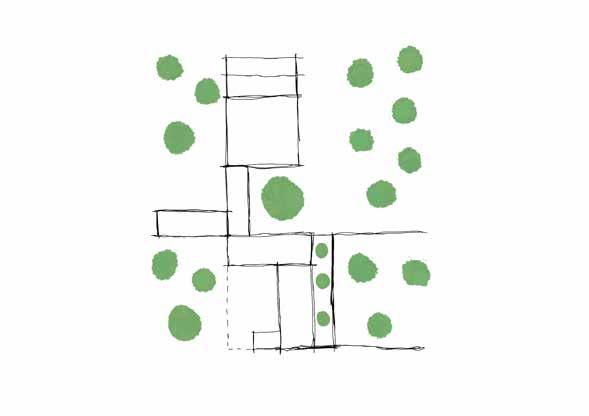
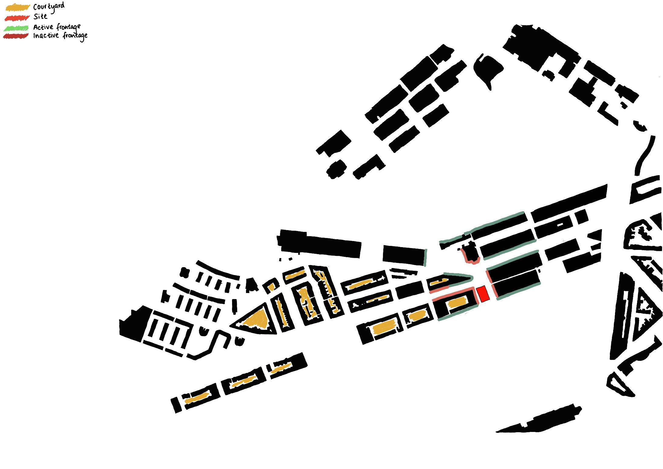

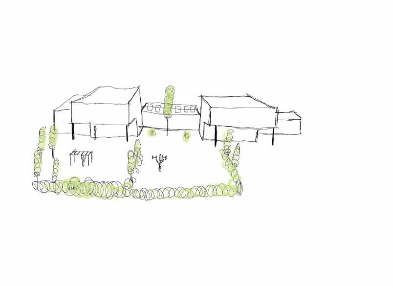
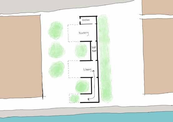
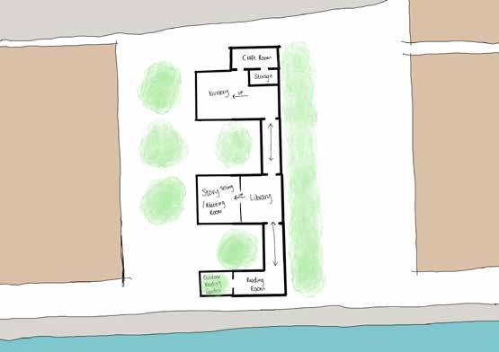
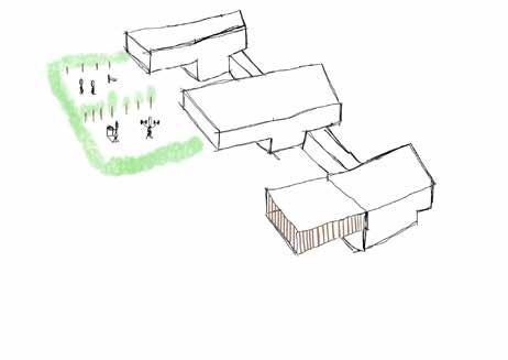
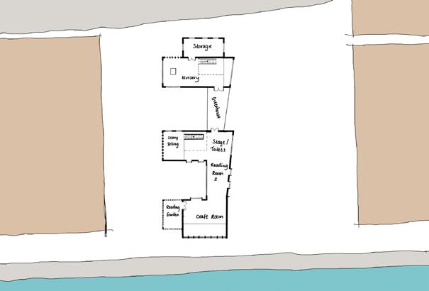


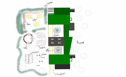
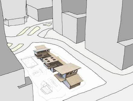
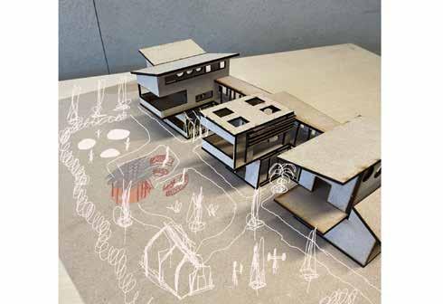
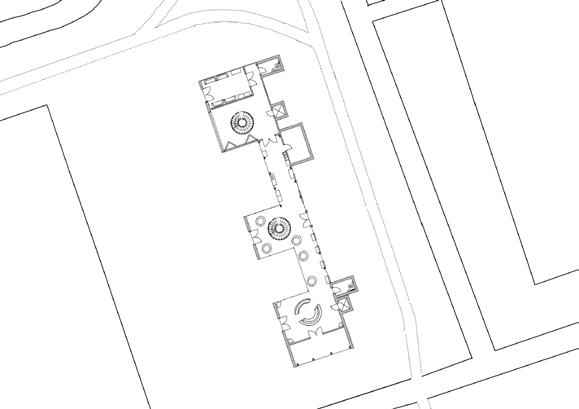
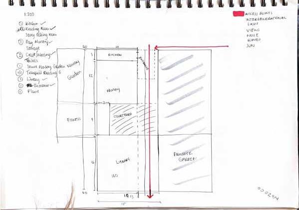
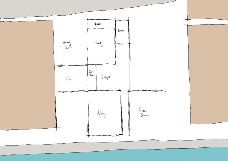
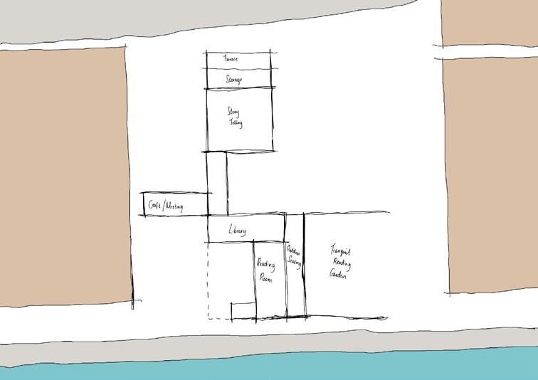
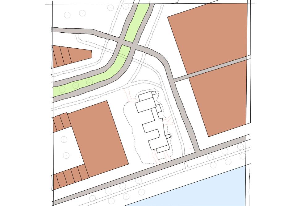
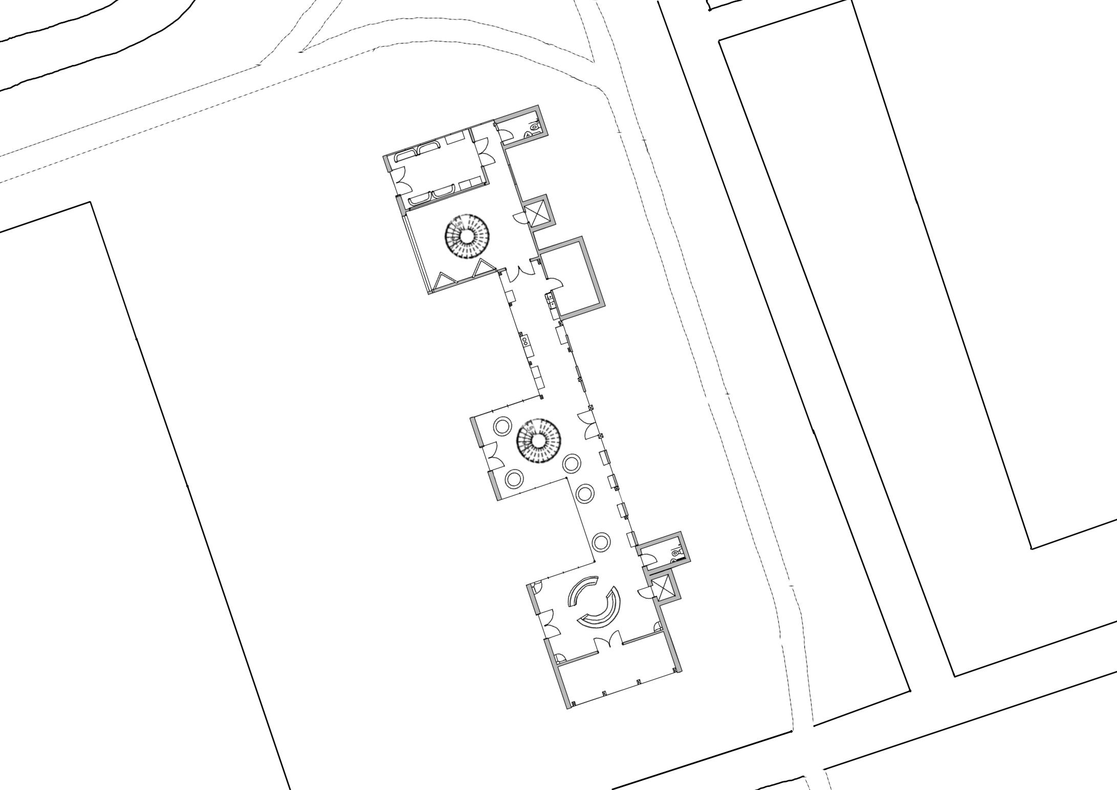
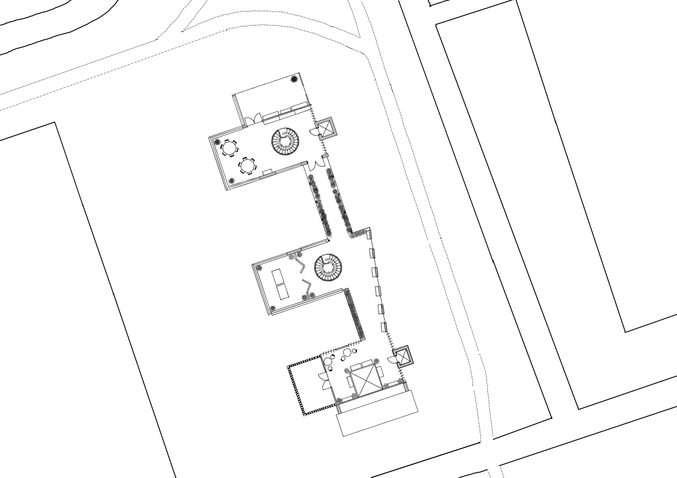
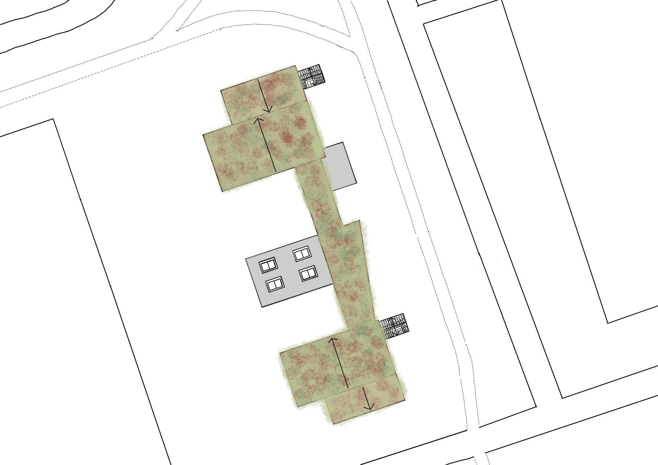
SITE PLAN WITH LANDSCAPE
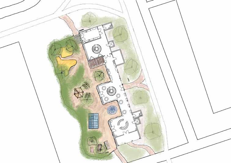
Encourages cycling as mode of transport which is better for the environment
Signage around the site support those that are less able
Lift access at both ends of the site allow access to elderly and disabled users
The existing path has been utilised and the new path is connected (shown in red on the 1:500 site plan)
The raised stage in the middle of the landscape (shows in 1:100 site plan) was inspired by Schouwburgplein to create the “city’s stage” and allow a space for story telling
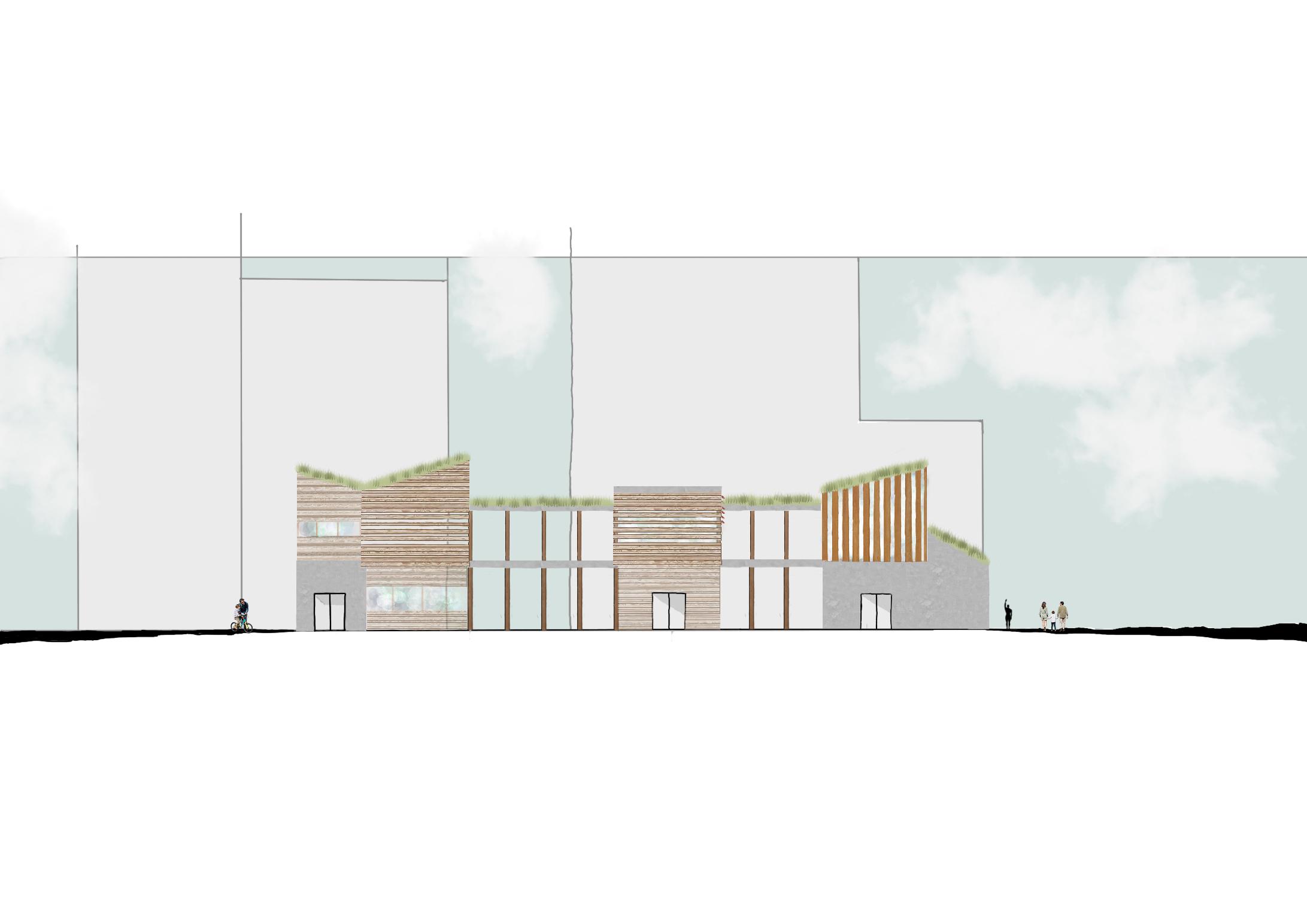
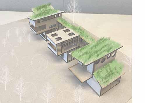

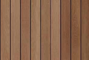


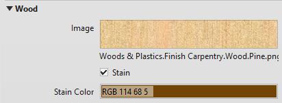
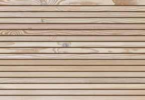 Western Red Oak vertical cladding
Douglas Fir Birch horizontal cladding
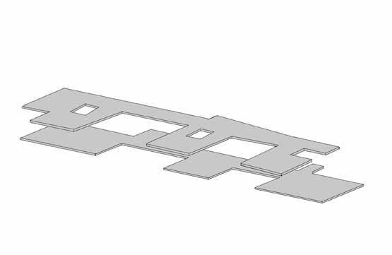
Precast Concrete walls & floors
CLT floor finish & walls
Western Red Oak vertical cladding
Douglas Fir Birch horizontal cladding
Precast Concrete walls & floors
CLT floor finish & walls
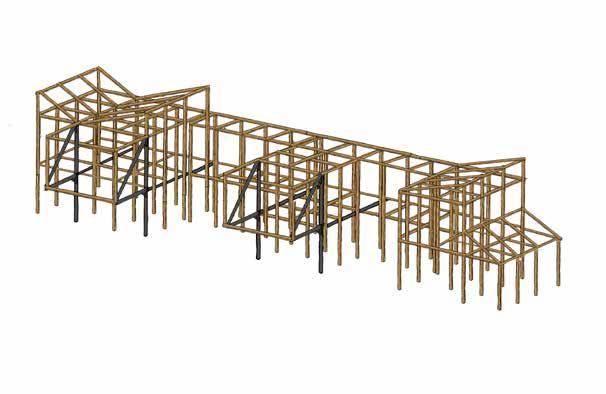
Steel beams for cantilever support, 100mm width, bolted to floor with steel plates

Cantilever concrete beam with steel reinforcements
References
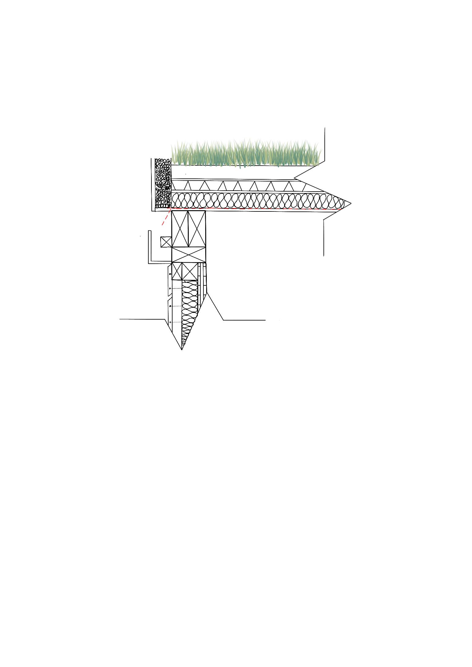
1 Gravel
2 50x50mm timber batten, 400mm centres
3 92x18mm Western Red Cedar rainscreen cladding (Timber, S. (2023)
4 50mm rigid insulation Celotex GA4050 (Direct, F.W. (2022)
5 Stainless steel flat head screw 30mm from edges
6 Planting
7 Soil
8 Filter
9 Drainage layer
10 50mm Kingspan Thermaroof TR27 Insulation (Market, M. (2023)
11 Vapour control layer
12 Plywood ceiling
13 Aluminium flashing
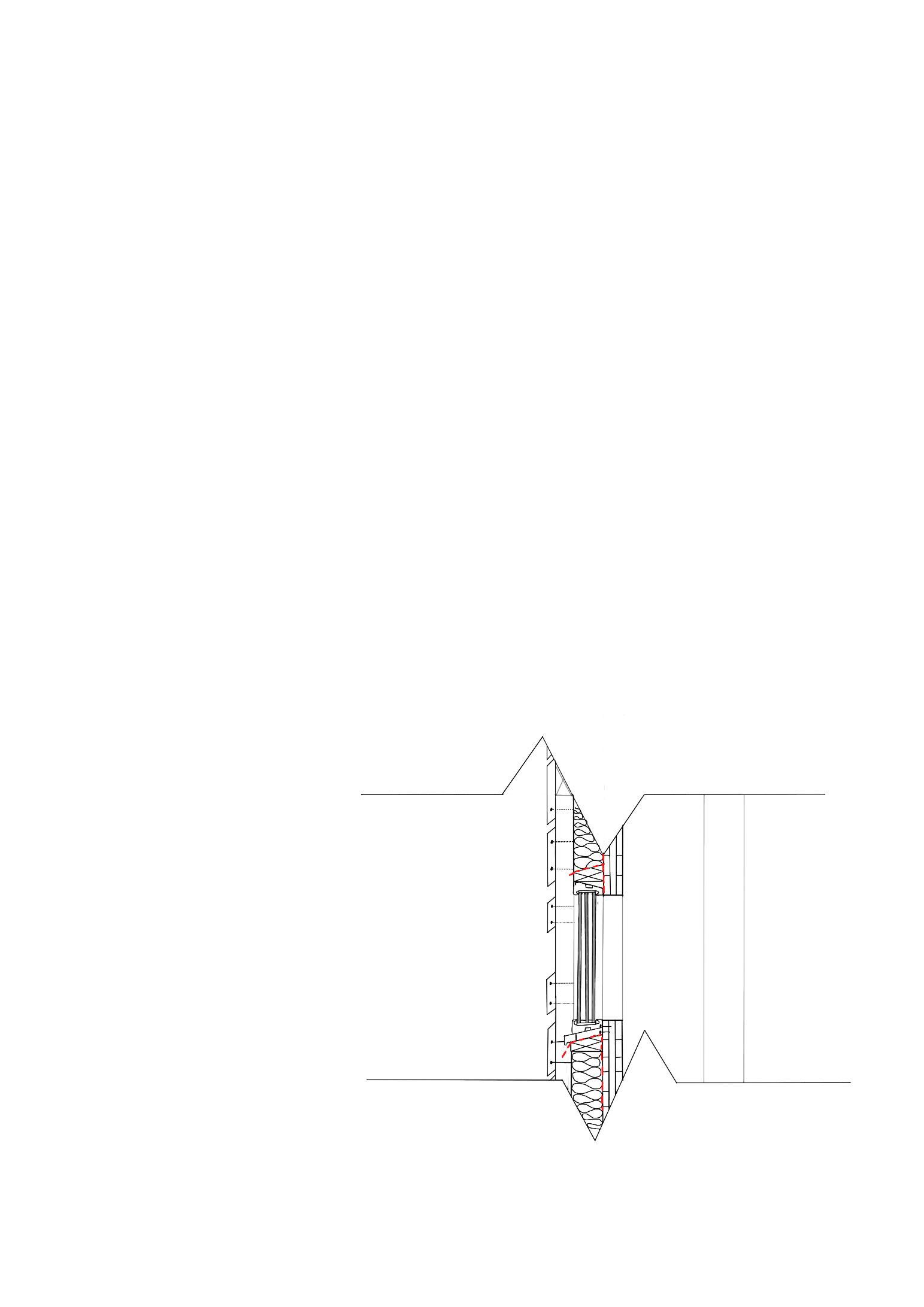
14 Triple glaze system LARA GF 60 mechanically fastened to CLT (Gutmaa, B. (2023)
15 Vertical glulam support beam
16 50x18mm Western Red Cedar rainscreen cladding (Timber, S. (2023)
17 Vertical glulam support beam
18 CLT 10mm x3 (Urban, E. (2023)
19 Glulam joist beam 100x50mm
21 OSB Layer 10mm
22 120mm Rockwool Flexi insulation (I, Hub. (2023)
23 Timber batten 50x140mm
24 Marmox Thermoblock 50x140mm (Marmox, T. (2023)
25 DPM
26 25mm PIR rigid insulation Ballytherm (Carvers, B.S.(2023)
27 Ground level (timber cladding and DPC 150mm above ground level to avoid water damage
28 Brickwork 150x210mm
29 20mm service gap cavity
30 Skirting
31 DPC and DPM overlap to improve cold bridging
32 CLT flooring (Structures, B.K. (2023)
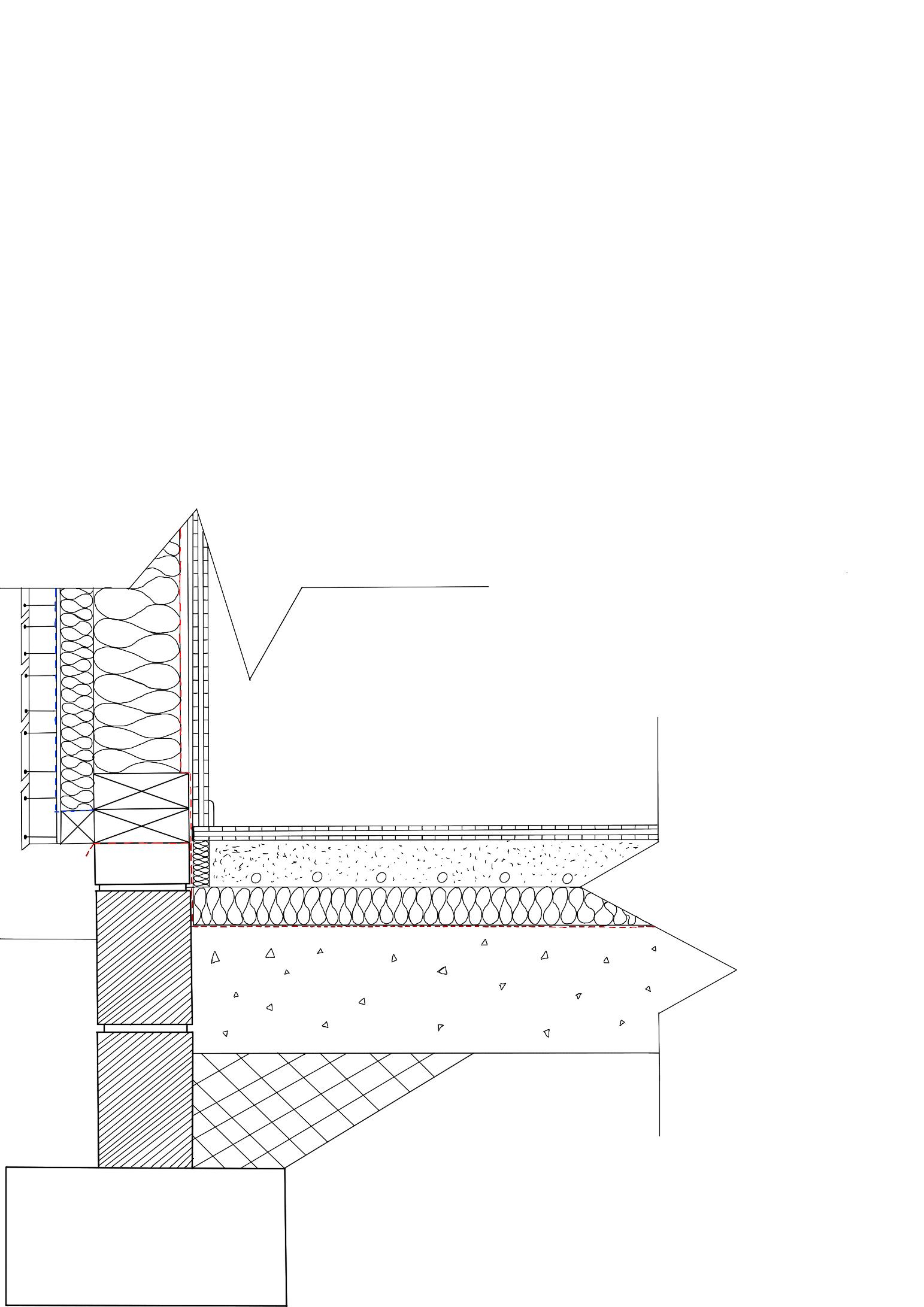
33 Screed 75mm
34 Underfloor heating pipes 16mm
35 50mm Celotex GA4050 PIR insulation (Superstore, I. (2023)
36 DPM
37 Concrete flooring 100mm
38 Hardcore 200mm
39 Foundation 450x300mm
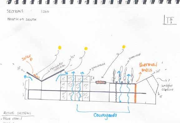
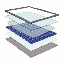
SOLAR PV PANELS
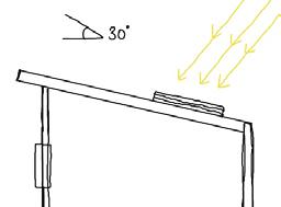
Solar panels on a 30 degree slanted roof pitch South facing for sunlight capture shown in
Figure 17. Figure 16 shows the layers of the PV panels.
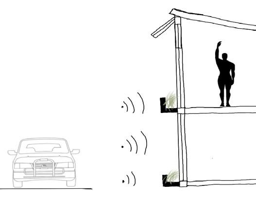
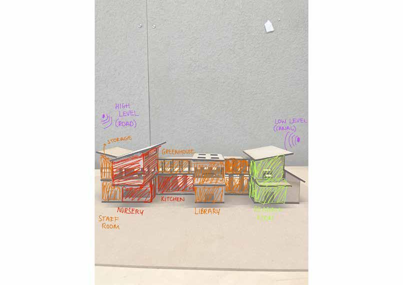
Plant beds are extruded along North facade floors to create an acoustic barrier from traffic noise pollution along the road that floods down the North side of the site. Plants absord and dissipate noise levels, whilst timber frame absorbs noise. Plants also provide calming views to staff room shown in Figure 20.
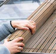
Adjustable sliding doors surounding courtyard areas to ensure future users can adapt the design to their needs,a nd provide ventilation in the Warmer months
Aluminium Frame
Tempered Glass
Encapsulant(EVA)
Solar Cells
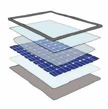
Encapsulant(EVA)
Back Sheet
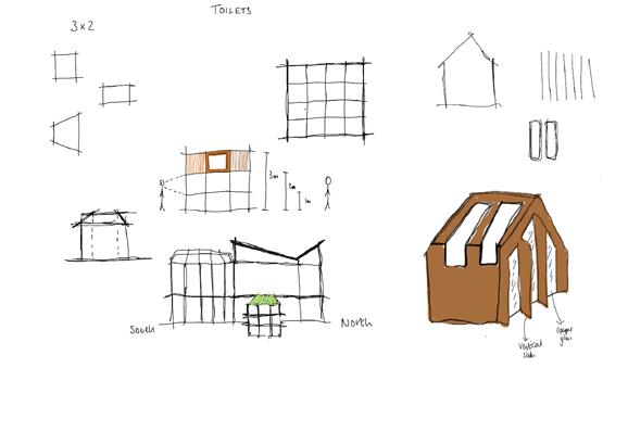
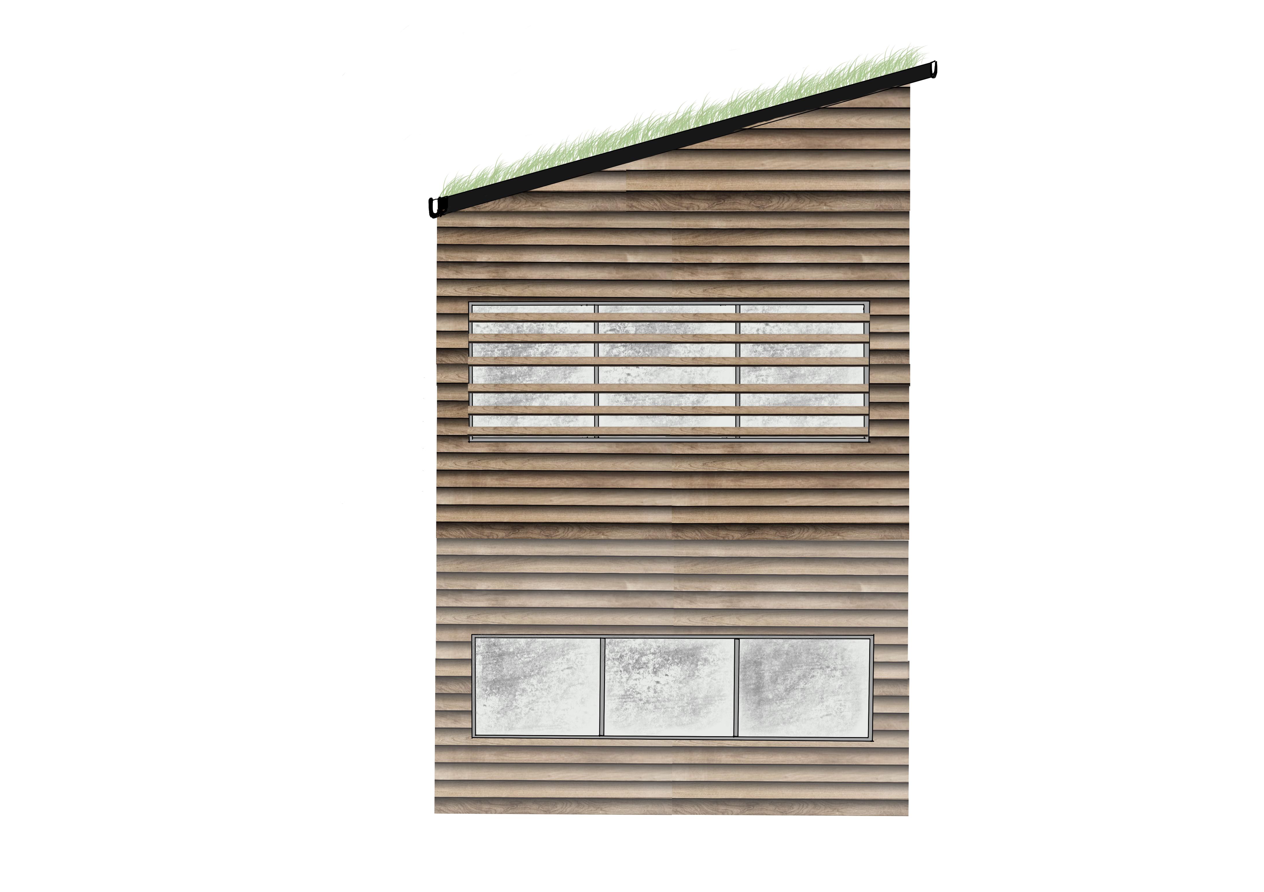
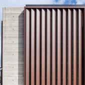
Figure 27 shows vertical louvres that are on the East and West facing glass facades on the second floor to maximise solar shading and diffuse daylight. Figure 28 shows external adjustable wooden netting to protect greenhouse plants from solar damage.
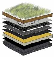
Figure 18 shows green roof layers utilised in my design. The green roof will improve biodiversity, reduce energy used for cooling of the South facing room in Summer months, and increasing run off retention of water (Vijayaraghavan, K. (2016)
INNOVATIVE MATERIAL
Glulam Beams
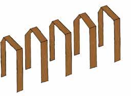
Glulam beams for greenhouse structure material since it has low carbon emissions in construction, and fire resistant in sunlight exposure in warmer Summer months.
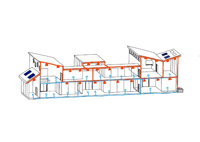
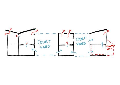
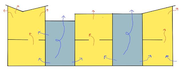
Courtyards shown in Figure 26 (blue) represents the use of cross and stack ventilation. A mixture of the two have been used due to a two storey high and narrow design, therefore courtyards have been used to maximise wind capture from the prominent South-West winds in Figure 4.
ACOUSTIC PANELS
Colourful accoustic panels to dissipate sound levels in nursery where noise levels are high, and also in the library where noise levels need to be low.See Figure 25.
Concrete flooring acts as a great thermal mass for holding solar energy to be released through underfloor heating when room drops to certain temperature.
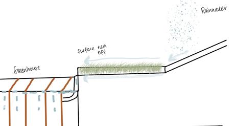
Figure 21 shows 25 degree pitch roof directing flow of rainwater to green roof and excess run off to greenhouse further South of the design. (Amoo,M. et al (2022).
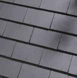
Concrete roof tiles used can be recycled, are easily manufactured, and durable against heavy winds in Rotterdam, rot proof to rainwater and insoluble to allow surface run off to flow rainwater into gutters and green roof (Roofing, D. (2019).
Triple glazing glass for the South facade window protects room from potential glare from South sun. Large South facing windows to maximise daylight & sunlight exposure.
26 (Author)
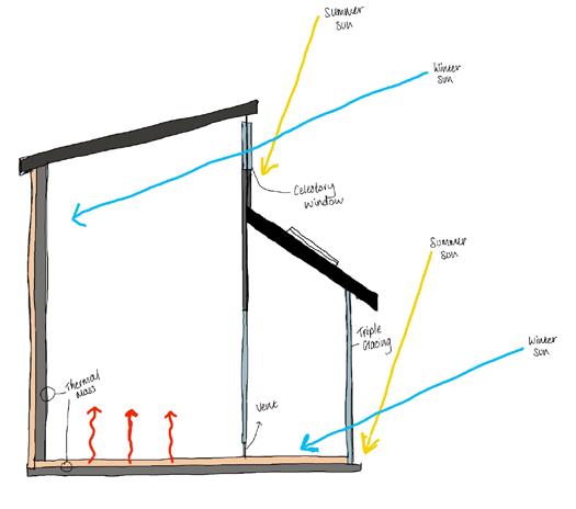
The celestory window in Figure 23 provides natural ventilation encouraging stale air to leave the room when open, and also has an overhang that shelters the room from the hot Summer sun, but allows access for the low Winter sun to enter the thermal mass concrete wall at the back of the room.
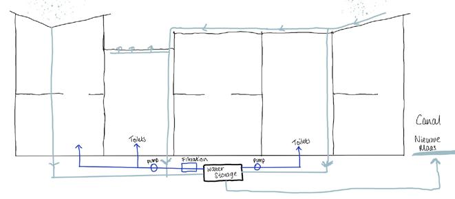
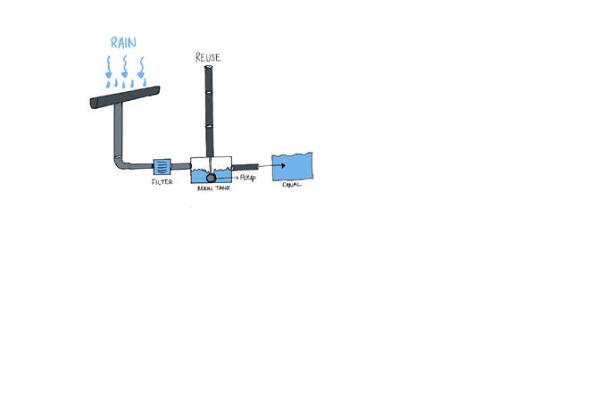
Overview of rainwater pathway from source at the roof to water storage tank which is then either pumped to resuse for toilet and sanitary water, or overflow to the canal Nieuwe Maas. See Figure 24
Trombe wall in Figure 23 has a concret flooring which is a great thermal mass for a South facing room to hold heat gained from solar capture during the day, and release at night. This encourages daytime cooling in Summer months and warming in Winter months and at night. A vent below the middle wall to allow hot stale air to leave the South room. This lowers energy consumption for room cooling.
 GREEN ROOF
All date and time settings for the renders are set to 21/12/22 12:00hrs, overcast sky
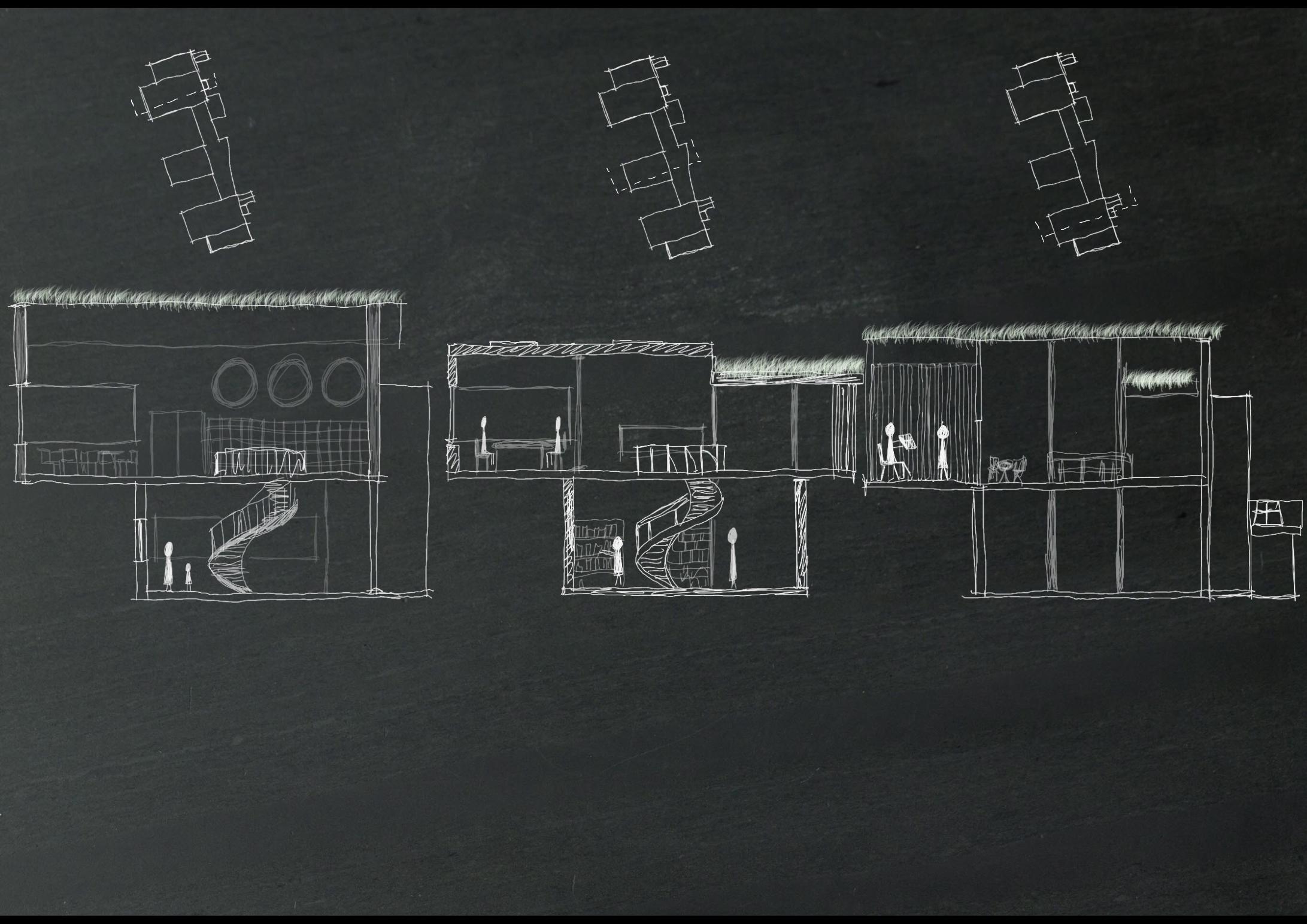
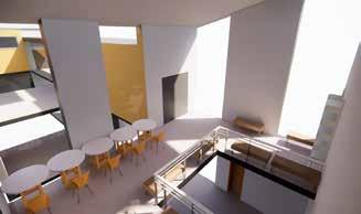
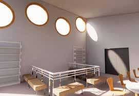
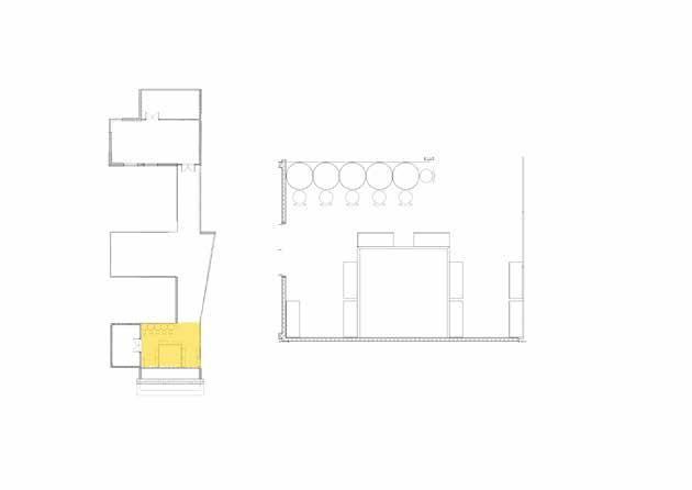
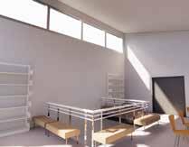
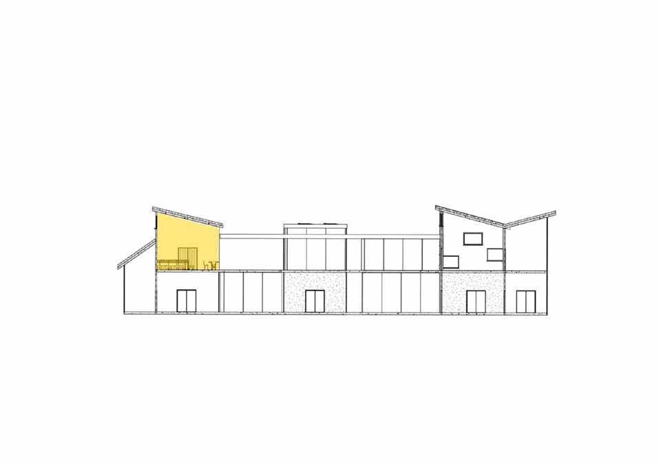
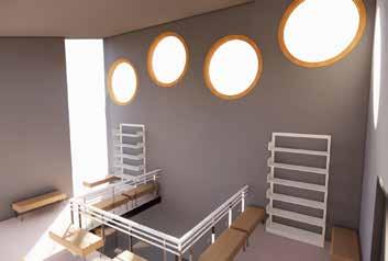
Selected space study is South facing, with a celestory window to the South, and bay windows to the North and East. It is located on the second floor of the building, and is a reading room with a void through the floor and a pitched roof. The windows are only above eye level to allow the reading room to have some privacy, but still catch views out to the East facade of the room. Figure 32 shows an example of morning light flowing through the room in equinox time. Ventilation is needed through the use of a celestory window since the room will get hot in the Summer months due to thermal mass and South facing facade.
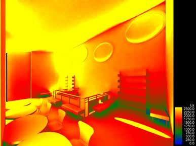
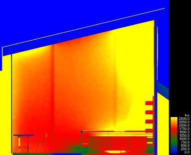
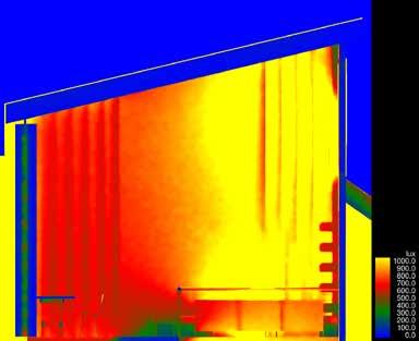
Illuminance levels around the majority of my space’s initial design are + 2500 lux which is 4x higher than the CIBSE (CIBSE, 2023) recommends a reading space to be (500 lux).
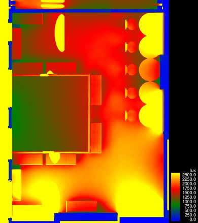
Bookshelves are placed in a good space on the South facade as this seems to be where less light reaches. Furthermore, the recommended lux levels for the lending area on CIBSE (CIBSE,2023) is a minimum of 200 lux, therefore placement of the bookshelves are necessary.
“human activity levels should increase in daytime or in bright light” (Kurniasih, S. et al (2019).
The windows on my initial design consist of a externally shaded celestory window to the South for ventilation, and bay windows to the North and East.
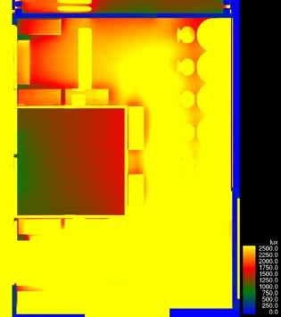
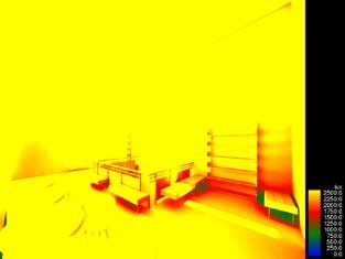
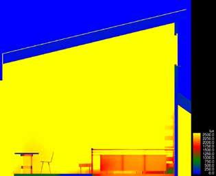
Changing the size of the windows has slightly decreased the illuminance on the tables on the North facade by 500-1000 lux, however this is still too high, aswell as the East seating benches. The rest of the room has decreased alot.
Decreasing the window size and shape has decreased the South facade illumance massively to 1000 lux where the bottom shelf bookself lies
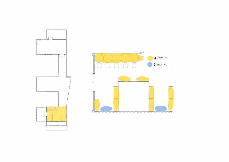
The selected space is a reading room, which requires enough light levels to be able to see a book infront of you whilst sat down, either at a table or with the book on your lap lower down. CIBSE (see Figure 33) rec comends a lux level of 500 lux. The reading room may have bookcases in on the South fa cade so 200 lux is required at this part of the room to be able to see bookshelves. See Figure 34.
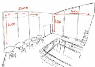
Figure 31 shows bookshelves in the room how ever not alot of light can reach them due to being on the on the same facade as the win dows.
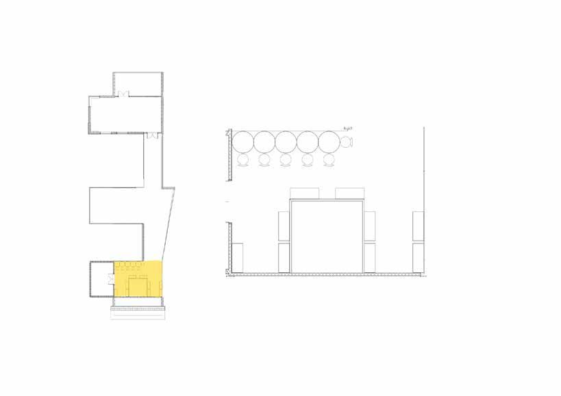
2 key spaces in the reading room:
Reading Area (yellow)
Bookcase (blue)
Figure 34 (Author)
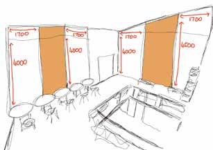
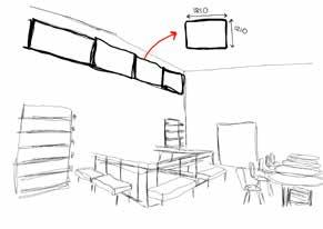
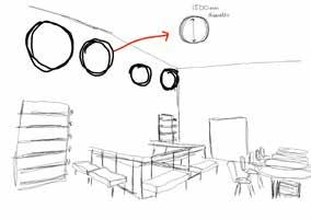
Changed location, shape and size of South facade WindowsFigure 57 shows how the size and shape of the South Facade windows have changed. They have been changed to circular 1500mm diameter from 1810x1210mm rectangles. This helps tocast a more interesting shadow on the space and avoids the harsh illuminance that the rectangular shape causes.
Decrease Size of North/East bay Windows
Figure 29 (Author) Figure 30 (Author) Figure 31 (Author) Figure 32 (Author) Figure 33 (CIBSE, 2023)Figure 44 shows decrease in lux after the material change of walls on the North, East, South and West to a darker colour and brightness shown in Figure 47. Altered areas are circled in blue on Figure 44.
Figure 45 and 46 shows a positive decrease in illuminance, espeically around each bookshelf on the South facade which is now down to 700 lux.
Maximum lux levels for the third iteration hav been lowered from 2500 to 1000 lux due to illuminance levels improving drastically with shading devices

Figure 44a shows the positive effect of material change (Figure 39a shows before) which has decreased in illuminance on the table which is my focused point of the room study for reading room levels to be atleast 500 lux. The material change has decreased the illuminance by around 500 lux.
I added 0 degree angle louvres to each of the four bay windows, shown in Figure 49. This has decreased the table area circled in Figure 49 from 1250 lux (Figure 44) to 700 lux however this still isn’t low enough, and the other tables are still at an illuminance of + 1000 lux. Glare from the window bays are an issue here, however these window types in Revit cannot be reduced in T-Vis.
To tackle this, I have altered the material of the louvres from Aluminium to timber wood, with a darker colour and brightness shown in Figure 56. I have also alteredthe angle of the louvres, shown in Figures 55, 59, and 60.
60 degree angled louvres decreases illuminance around bookshelves to desired lux level of between 200-300 lux.
Figure 47 shows the 45 decrease level in brightness on the walls of the room shown in Figure 44, and also the change in colour from 290 RGB to 140 RGB


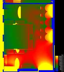


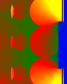
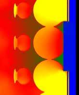
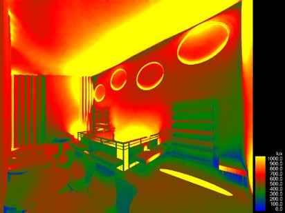
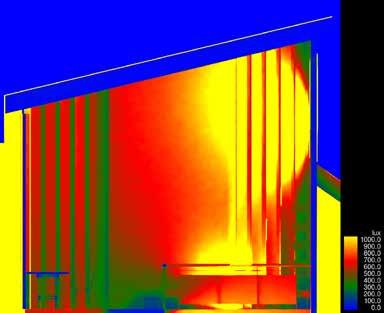
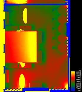
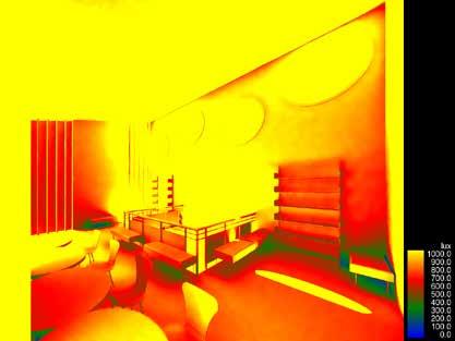
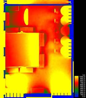
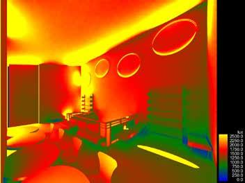
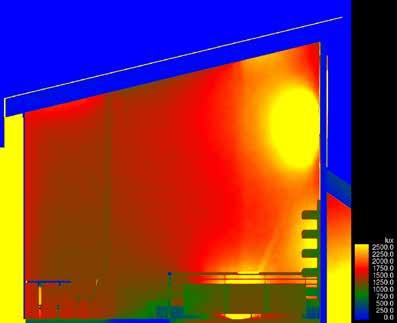
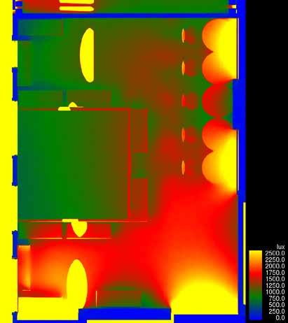
Table areas where users will be reading has also reached the desired minimum lux level of 500 lux, whilst chairs are slightly lower between 300-400 lux which shows glare will be minimal in users’ eyes allowing them to read
Figures 59 shows the illuminance caused from a 0 degree angle plane of louvres on the East facade, which reflects too much light into the room, and the views out to the South canal are restricted.
Figure 60 shows the improvement of daylight reflectance into the room at a shorter distance due to a 60 degree angle. This angle also increases the view out to the South canal from where users in the space will be seated / travelling through the space whilst reading.
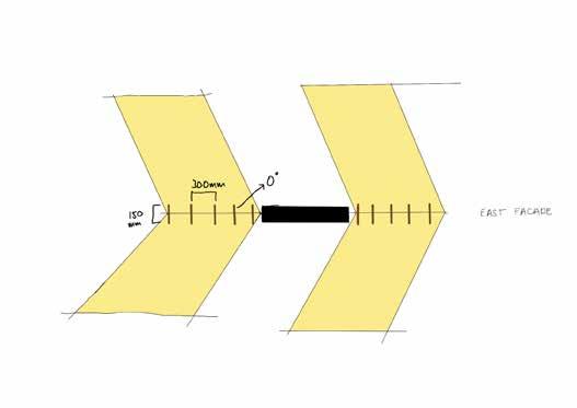
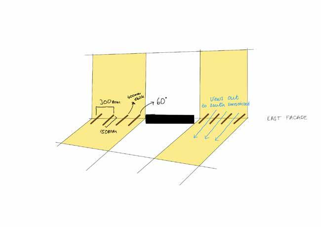
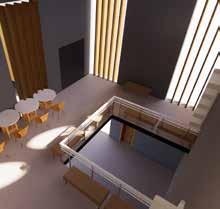
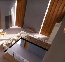 Figure 44 (Author)
Figure 45 (Author)
Figure 46 (Author)
Figure 47 (Author)
Figure 48 (Author)
Figure 44 (Author)
Figure 45 (Author)
Figure 46 (Author)
Figure 47 (Author)
Figure 48 (Author)
Water Collection System
My building has a pitched and green roof system that enocurages ecology and rainwater harvesting. The pitched roofs shown on Figure 62 collect any rainwater by sending the flow path into gutters along the edge of the building.
These gutters lead to a single water pipe underground that is sent through filtration before entering the main water storage tank also shown on Figure 62. In times less precipitation, water is pumped out of the tank and outside to water the landscape around the site. On the contrary, times of excess or heavy rainfall is supported by the storage tank to allow this water to sit underground for further use of recycling.
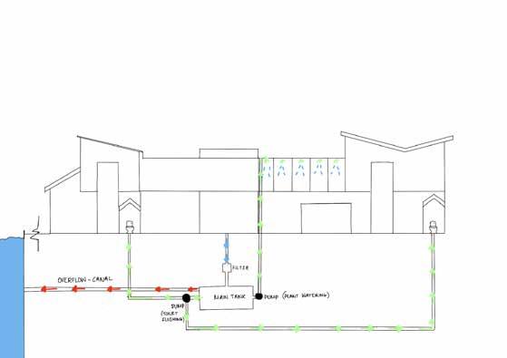
Water Distribution System
Figure 63 shows how water is distributed throughout the building after being treated underground. A pump sends the water to toilets when they are flushed which is a simple connection.
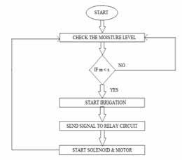
However, plants in the greenhouse are connected to an automatic irrigation system. This system is common, however an example of one is a microcontroller found in a study (Gupta, A. et al (2016)that senses the content of moisture in the soil and automatically sends signals to the pump to turn on. See Figure 65 to for steps of this system.
PITCH SOUTH
PITCH NORTH 2 GREEN ROOF
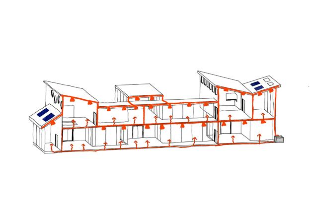
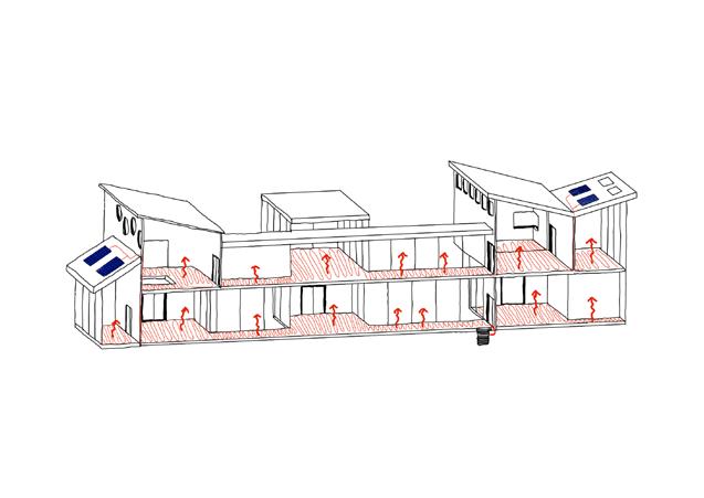
Underfloor heating system is made up of layers shown in Figure 72. A BMS system is used to automatically pump either hot or cold water through the underfloor pipes to regulate the building’s temperature according to season, and provide thermal comfort for users (Farid, M. et al (2001).
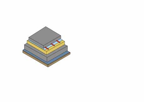
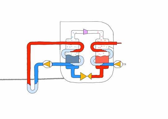
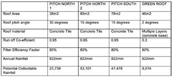
Figure 73 shows potential collectable rainfall from different roof systems designed for rainwater harvesting. Concrete tiles have been used for the pitched roof as they don’t pollute the pH levels of water very much, making the filtration process easier (Lai, Y.H et al (2018). A slight 2 degree pitch roof for the green roof has been used to prevent water pooling (Magazine, W. (2011). Figure 63 shows locations of each roof.
Figure 73 References: Run off Coefficient (Publishing, I. O. P. (2019)
Filter Efficiency Factor (Agency, E. (2009)
Annual Rainfall (Climate, W. &. (2023)
I am using a hydraulic lift over a traction lift because they are easier to install, have lower carbon emissions when transporting, and cost less to run (Elevation, TK. (2023). An MRL (machine less room) hydraulic elevator was considered, however the only reasonable advantages of this in stead of a machine with the room externally rather than underground was that it could reach floors more efficiently. This isn’t necessary since my design is only two floors, and it would cost more
Potential collectable rainfall (litres) = roof area (m2) x run of coefficient x filter efficiency x annual rainfall
Formula for Figure 73 Table (Agency, E. (2009)
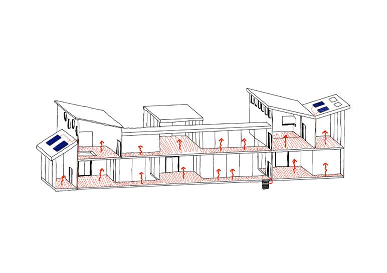
The heat pump shown in Figure 67 (heating in the Winter, however can reverse effect and provide storage in Winter months) is a system that works by heating pipe fluid with geo-thermal energy in the ground through boreholes that are no more than 10m deep underground. The fluid circulates through a cycle of evaporation and condensation. In the evaporator coil, the fluid is evaporated at a low pressure and absorbs the heat. Then, it is compressed in the condensor at a higher pressure. The heat created from this system is then pump back into the underfloor pipes (Wu, R. et al (2001).
Solar panels shown in Figure 65 are on 30 degree pitched roof on the North and South facade to capture maximum solar energy from the sun angle in the Summer (38 degree angle mentioned in Figure 2, after researching a study found a 30 degree pitch is the most efficient angle for capturing solar energy (Li, H. et al (2020).
The solar panels store and resuse solar energy which is transferred through the ground source heat pump shown in Figure 67 by going through a process heating and cooling water through a pipe system shown in Figure 66 where water is either condensed or evaporated to heat and cool the building accordingly to seasonal weather (Trillat-Berdal, V. et al (2007).
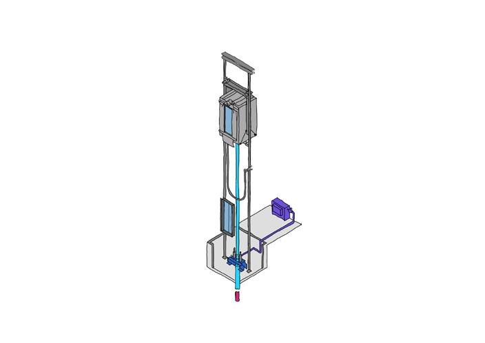
The hydraulic lift system works by pumping oil into the pipes to operate a piston system of moving up and down. When the lift goes down, the oil will be sent back through the pipes and vise versa. The car buffers are there for a safety precaution to stop the cabin going below the point required. The pump is stored inside the motor in the maintenance room to reduce carbon emissions and noise pollution. See Figure 67 for locations of elements.
Car Buffers
elevator
Height = Elevator Travel Height
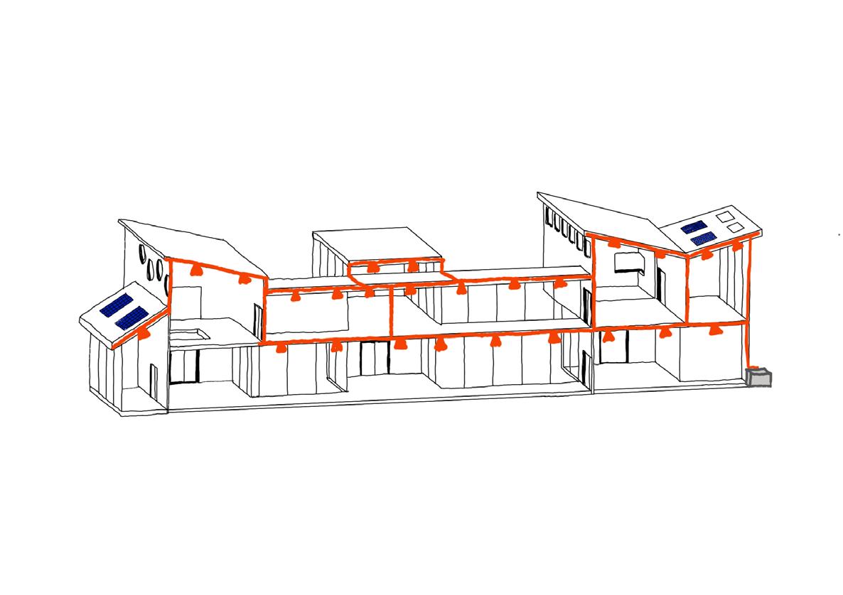
Figure 68 shows the location of the HRV system (Heat Recovery Ventilation) installed in my design shown in Figure 69. This system works by cycling fresh and stale air in and out of the building through an outlet driven by two different circulation fans. The air is filtered and dragged through a heat exchanger core. This system aims to improve indoor air quality which is particularly important for environmental reasons as, according to a study, humans spend 90% of their life indoors (Ghida, D. (2019).
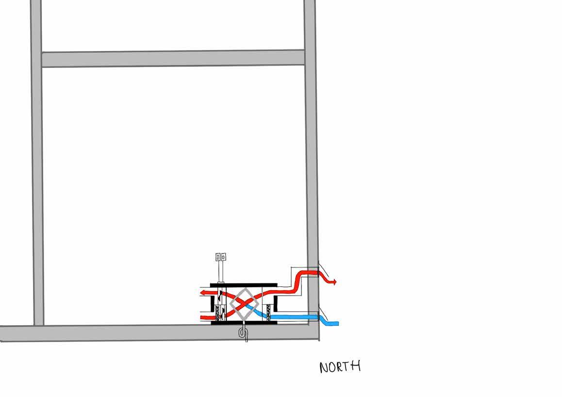
It is a decentralised HRV system, meaning ducts shown in Figures 70 and 71 provide ventilation for the whole building.