
Part 1: Process

The process for modeling complex structural forms in RISA, a structural engineering software, can be time consuming which presents a barrier to the design team. If the interaction between RISA and the complex geometry in the design software can be automated then a feedback loop can be implemented. This builds confidence in design, reduces cost and can reduce embodied carbon.

Existing Workflow
Manual Process
Design Intent Concept Sketch
Manual Input
Plates
RISA Model Analysis
As Architects and Designers, we strive to refine our craft and transform the built environment. Schools of thought like the Bauhaus have taught us design principles such as:
-Minimalism; not using excess materials and elements
-Form following Function; where the design is based on the function of the space
-Truth in Materials; Where the materials reflect the nature of the object and building
These schools of thought are now being continued and further developed by trends such as:
-New technologies, allowing for new ways of expressing structure, materials, and forms that need to be analyzed.
-Reducing waste, via reduction in additional and unnecessary intermediate structural assemblies that have emerged due to increased number of trades and increased thermal performance.
-Reducing carbon, via reduced structural weight
In practice these issues can hit a roadblock or break in the process when the design is the structure and the structure is the form. Complex forms can become a barrier, making it difficult for the engineer to be able to quickly and efficiently model and analyze the structure. Therefore, the engineer is often hesitant to model these forms, or only can realistically model it one time. Without a feedback loop from the engineer, meeting the projects schedule, budget, and sustainability goals can be difficult. An iterative process of modeling and analyzing with a feedback loop is needed if we are to meet these goals. One of the problems facing design teams is in the attempt to optimize and iterate. Currently, there is not a way to connect the designer natural workflow iterations with the structural analysis tool RISA.
The process defined here strives to resolve these issues. It allows the designer to use the design tool of their choice and export the data in a format that can be consumed by the structural engineering software, RISA, for analysis. It also does not use complex coding or APIs and is easily adaptable and simple. Since the process is exposed, it is verifiable and can be checked or audited by the engineer and architect to build confidence in the process instead of being a black box.
The old workflow (diagrammed above) is as follows: The design intent is communicated to the engineer with a 3d model or via 2d drawings. This is then manually input into RISA by typing in these measured x,y,z coordinates for each plate corner. This manual input is time consuming and takes the engineer significantly more time than the actual structural analysis process such as loading, calculations, and verification. This process is also prone to error as it is manually input and the design intent can be misunderstood. Once the analysis is complete, any changes based on the output requires rebuilding the model, often from scratch, resulting in starting the process over again.
Model 2D
/ 3D ModelJoint Coordinates Design feedback based on analysis (Time Permitting) RISA (Structural Engineering tool)
3
Proposed Workflow
Design Intent Concept Sketch Model
Engineer Modeling Criteria
The proposed workflow eliminates the manual modeling and re-modeling process inside RISA by interjecting a few simple steps. The proposed process (diagrammed above) is as follows: The architect shows the engineer the design intent. The engineer can provide criteria about how to model the surfaces so that the engineering can be done properly as required by RISA such as where and how certain elements like floors, plates, tubes, and material thicknesses can be modeled. This step has the added benefit in that it requires the designer to model the form with accuracy and rigor that can identify issues in the aesthetics that can quickly be fixed before sending to the engineer. From this 3d model, the computational script (diagrammed on the next page) takes all the corner points (joint coordinates) and surfaces (plates) and writes them in a spreadsheet in a format that is ready for RISA. The engineer can then copy and paste from the spreadsheet into
RISA. The process from the spreadsheet to the model in RISA can occur in under a minute, regardless of the complexity and scope of the structure. Once the loading has been setup and the analysis run, the engineer can quickly provide feedback to the designer. The designer can then make revisions and modifications to the design. If the 3d modeling step is parametric, member sizes or geometry can be quickly changed and re-exported for another rapid analysis and feedback loop.
This workflow provides more opportunity for the design intent to be met, structural expression to be simplified, and materials to be simplified to ultimately reduce the amount of embodied carbon.
The next section will explore the genesis for the workflow and demonstrate where the idea came from and how it has been adapting and evolving on real project workflows and schedules.
3D
Model 3D modeling program of choice
Comp. Design Grasshopper or DynamoJoint Coordinates Plates Joint Coordinates Plates RISA Model Analysis Design feedback based on analysis See next page for diagram of this step Manual Process Automated Process Manual Spreadsheet RISA
4
Computational Script Breakdown
Joint Coordinates
Remove Duplicate Points
X
Location of Each Point in 3D Y Z
Generate Labels for each Unique Point
Surface Geometry Surface Corner Points
Plates
Location of Each Point in 3D
Unique and consistent labels are created for points by concatenating the rounded number separated by underscores: [ (Rounded X) _ (Rounded Y) _ (Rounded Z) ]
Spreadsheet
Label X Y Z
Spreadsheet
Joint A Joint B Joint C Joint D
Generate Labels for each surface corner Point
Y Z X
5
Part 2: Genesis
Where the idea for the workflow came from and how it has been adapting and evolving on real project workflows and schedules.
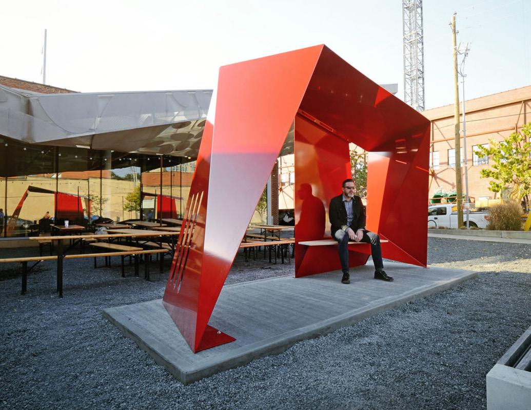
go[shelter] Bus Shelter
Concept
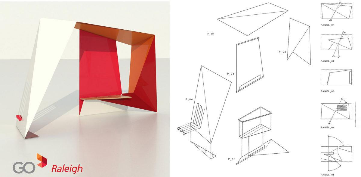
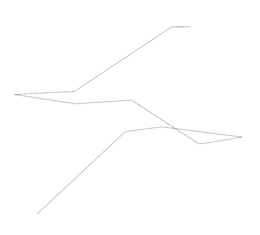
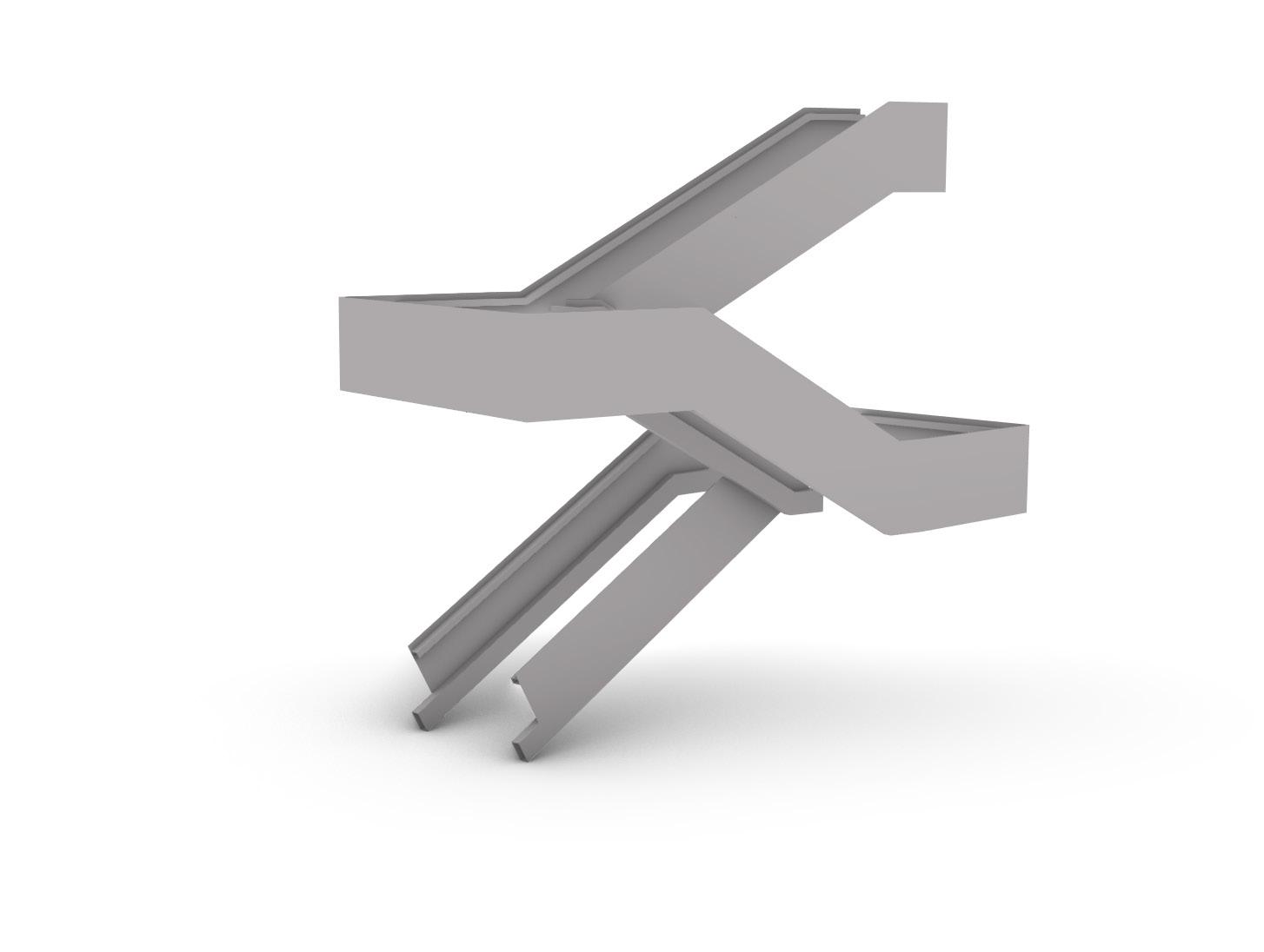
The premise of the go[shelter] is to elevate the status of regional bus travel for all passengers. Conceptually it is envisioned to comprise a graphically intense and recognizable system of landmarks in the urban scape. The prototypical shelter is a folded line of steel that con nects points and shelters riders while contributing and strengthening the Go Raleigh brand. The concept can be implemented throughout the region remaining true in it’s formal expression while having the flexibility to adapt to iconic graphic requirements. The go[shelter] re interprets the transit system graphics into a dynamic, sculptural and functional form that is altogether simple in its execution.
This example was a solution to a design competition where the winner’s entry would be constructed. Our firms internal competition group called ‘Combustion Chamber’, intrigued by the brief, set off designing. There was a strict budget and constructibility was forefront in the designer’s concepts. The intent was for the folded form to be architecture and structure. Due to the complex form and the lack of traditional framing members the engineers had difficulty modeling the form quickly and efficiently.
As a result, the architecture team began to question the constructibility of their concept. The team was looking for feedback about their concepts to refine and iterate based on the engineers analysis, but it did not come quickly enough since the modeling process was so difficult for the engineers. Despite these challenges, the project was a success, won the competition, and was built.
Part of the mission for Combustion Chamber is to question traditional ways of working by using new tools and workflows. A direct result of this project was observing the struggle that emerged when trying to implement a complex structural form. This was the genesis for the idea to improve workflow.
After the project was completed and built, this shelter’s form was used as a test to try and improve the workflow between architectural design intent and structural analysis. An estimated 1/2 a day of time was saved using this method. The following pages illustrate the new workflow concept that emerged. It helped prove that the idea was feasible, accurate, time saving and could be used on projects in production.
Design
8
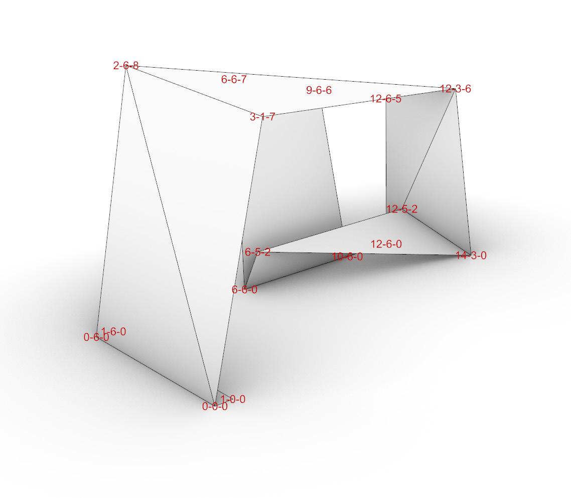
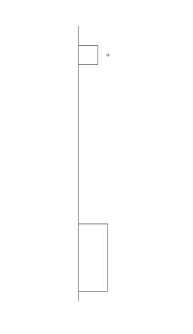
Design concept model by the Architect also showing the labels for each corner point as determined by the computational design script [Top Left]
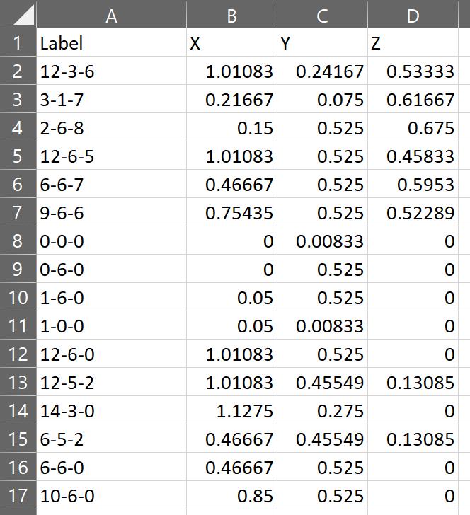
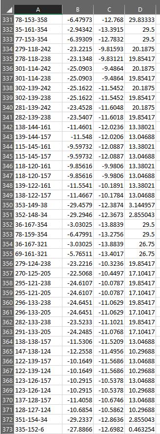
Spreadsheet generated by the script showing the joint labels and the x,y, and z coordinate points formatted to import intro RISA [Top Right]
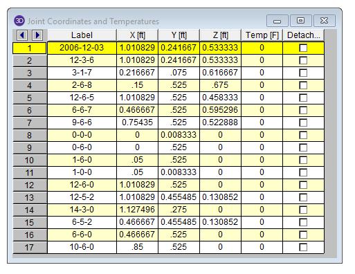
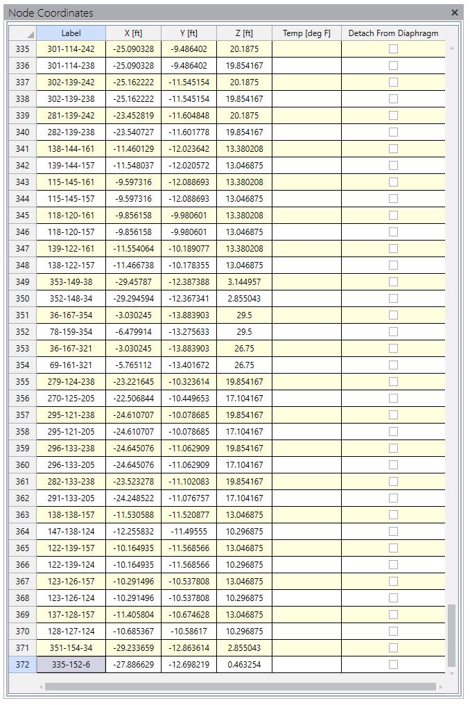
RISA Joint Coordinates panel after pasting in the data from the spreadsheet showing identical data to the spreadsheet. [Right]
Joints 9
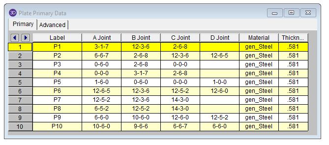
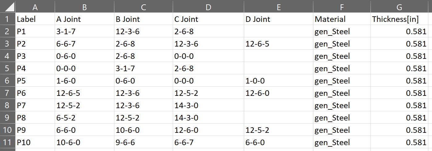
Plates
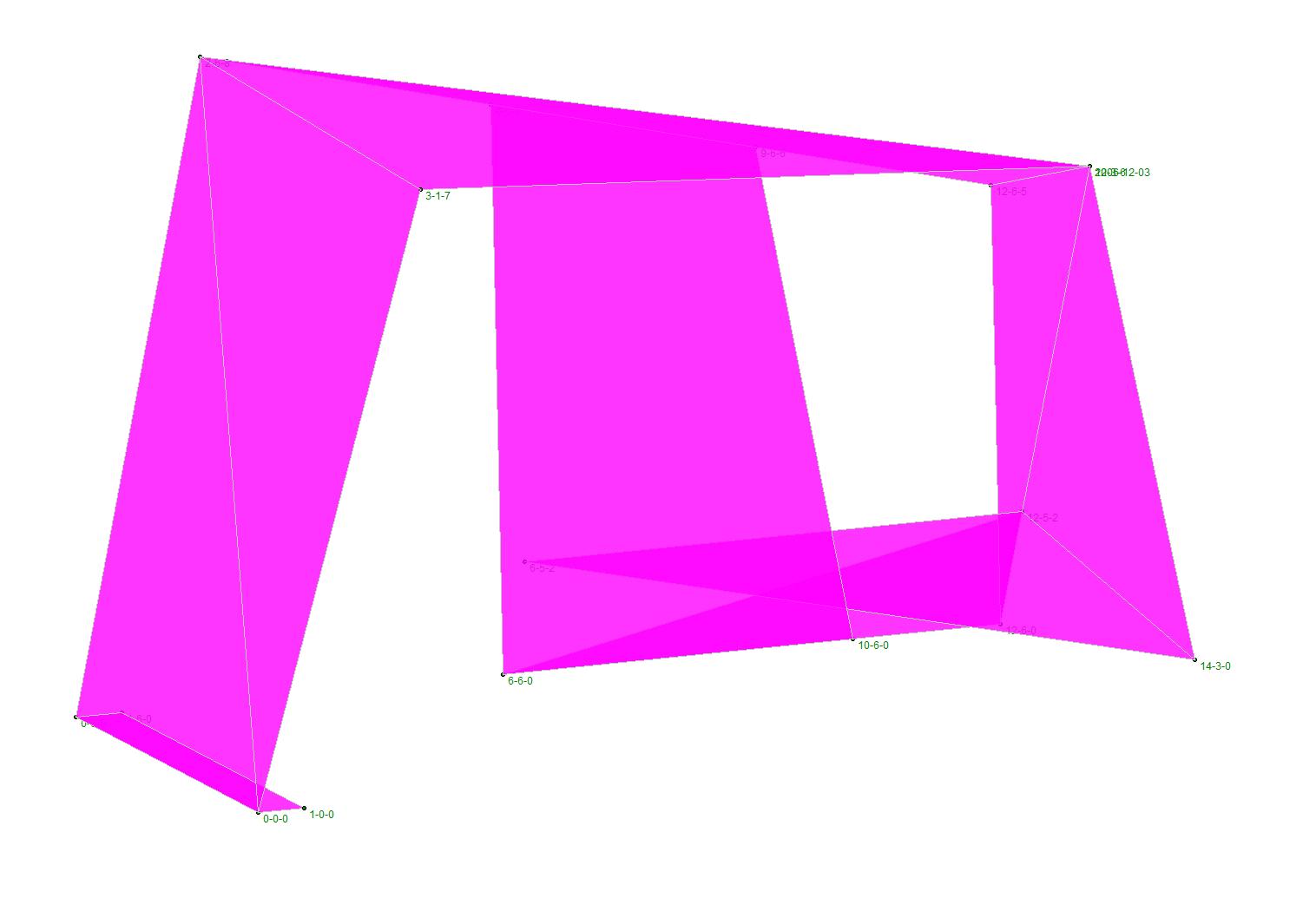
3D model in RISA showing the new plate geometry and joint coordinate points [Left]
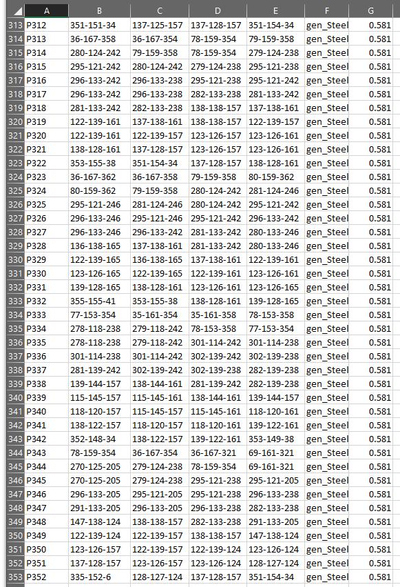
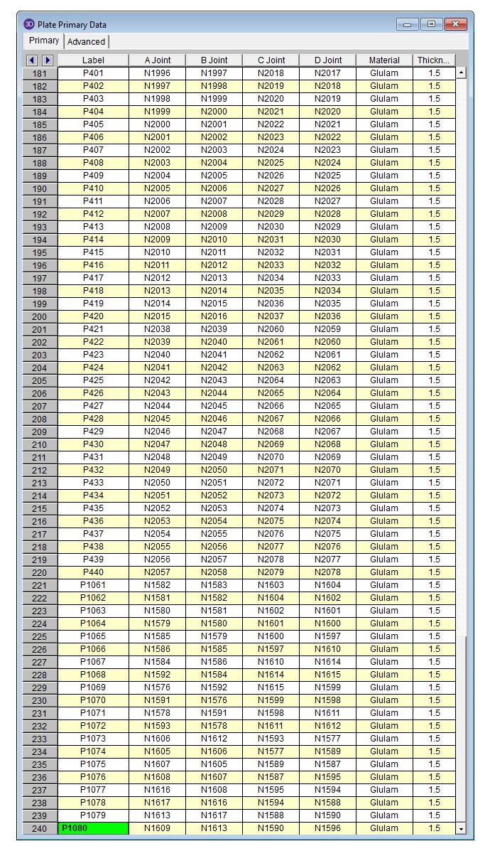
RISA Plates panel after pasting in the data from the spreadsheet showing identical data to the spreadsheet. [Bottom Left]
Spreadsheet generated by the script showing the panel labels and the 4 joint labels formatted to import intro RISA [Bottom Right]
10
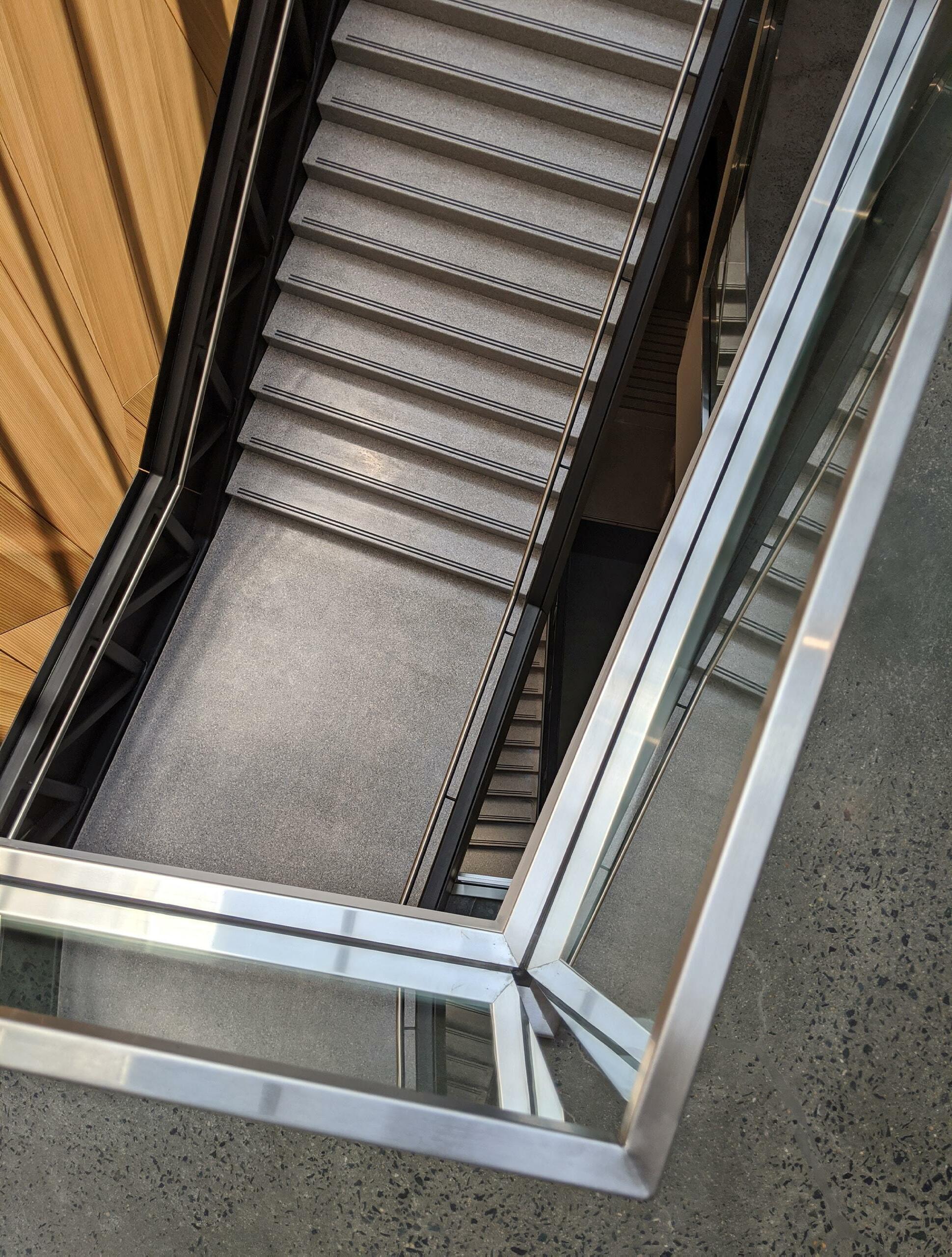
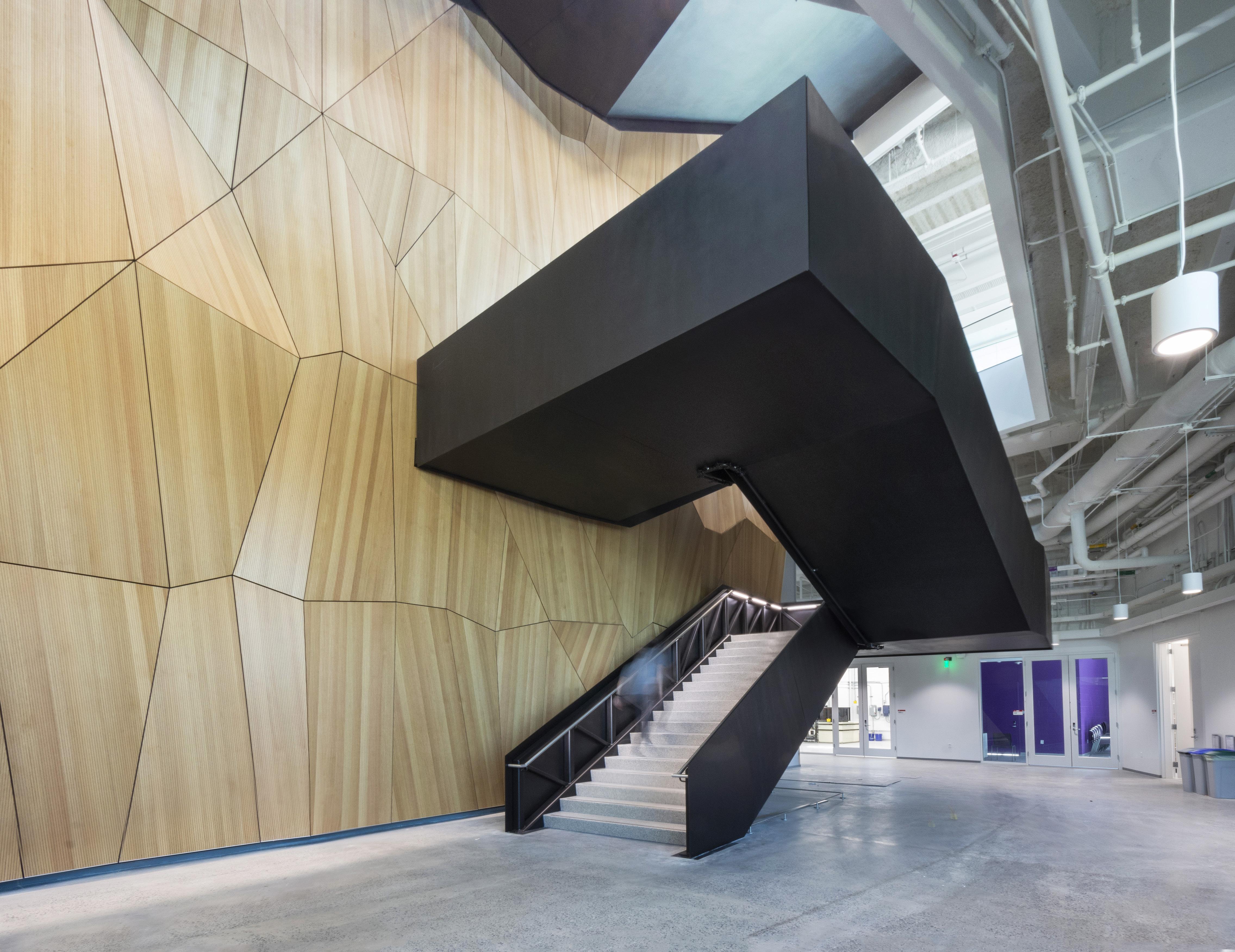
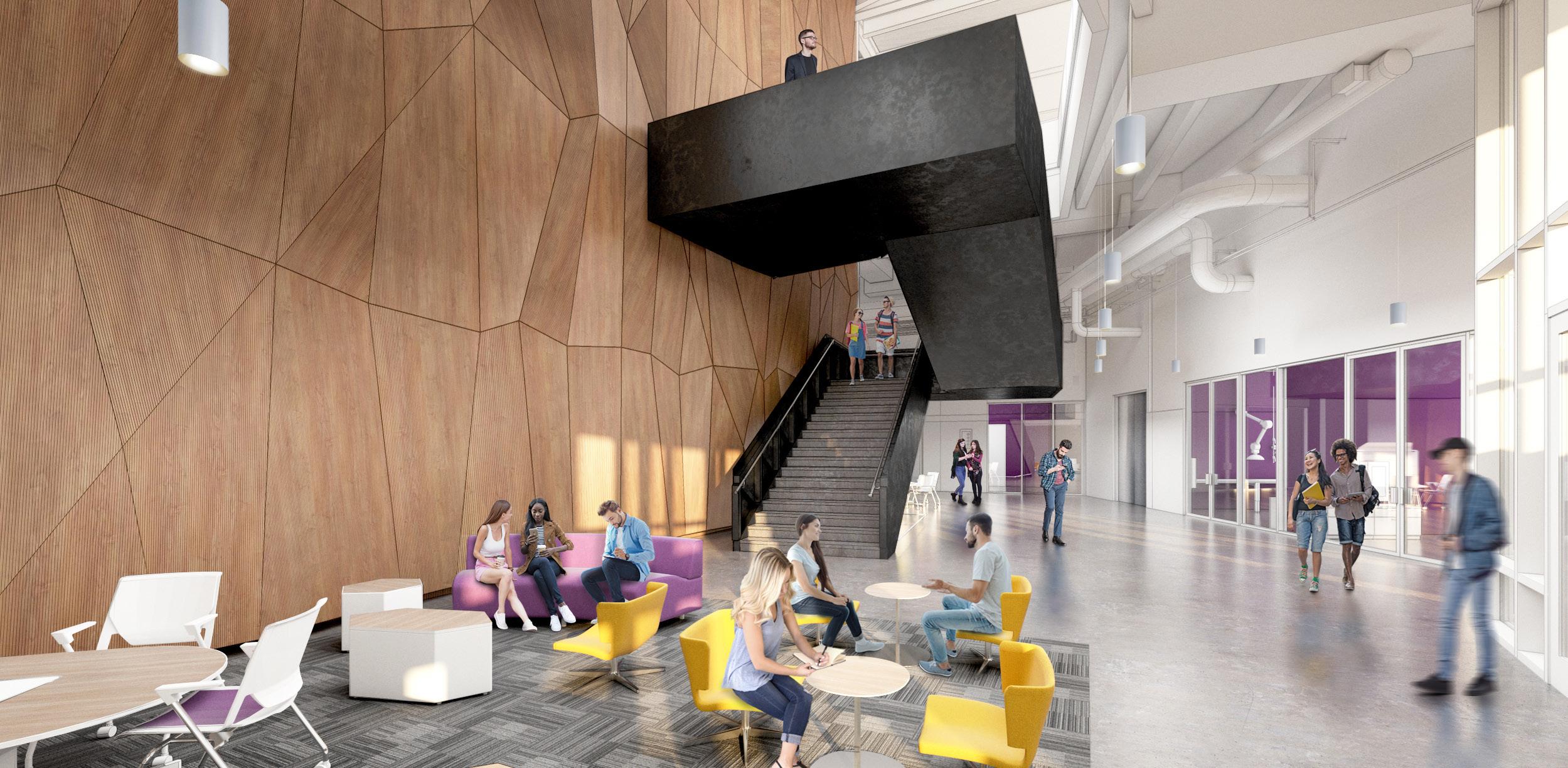
Fitts-Woolard Hall Monumental Stairs
Design Concept
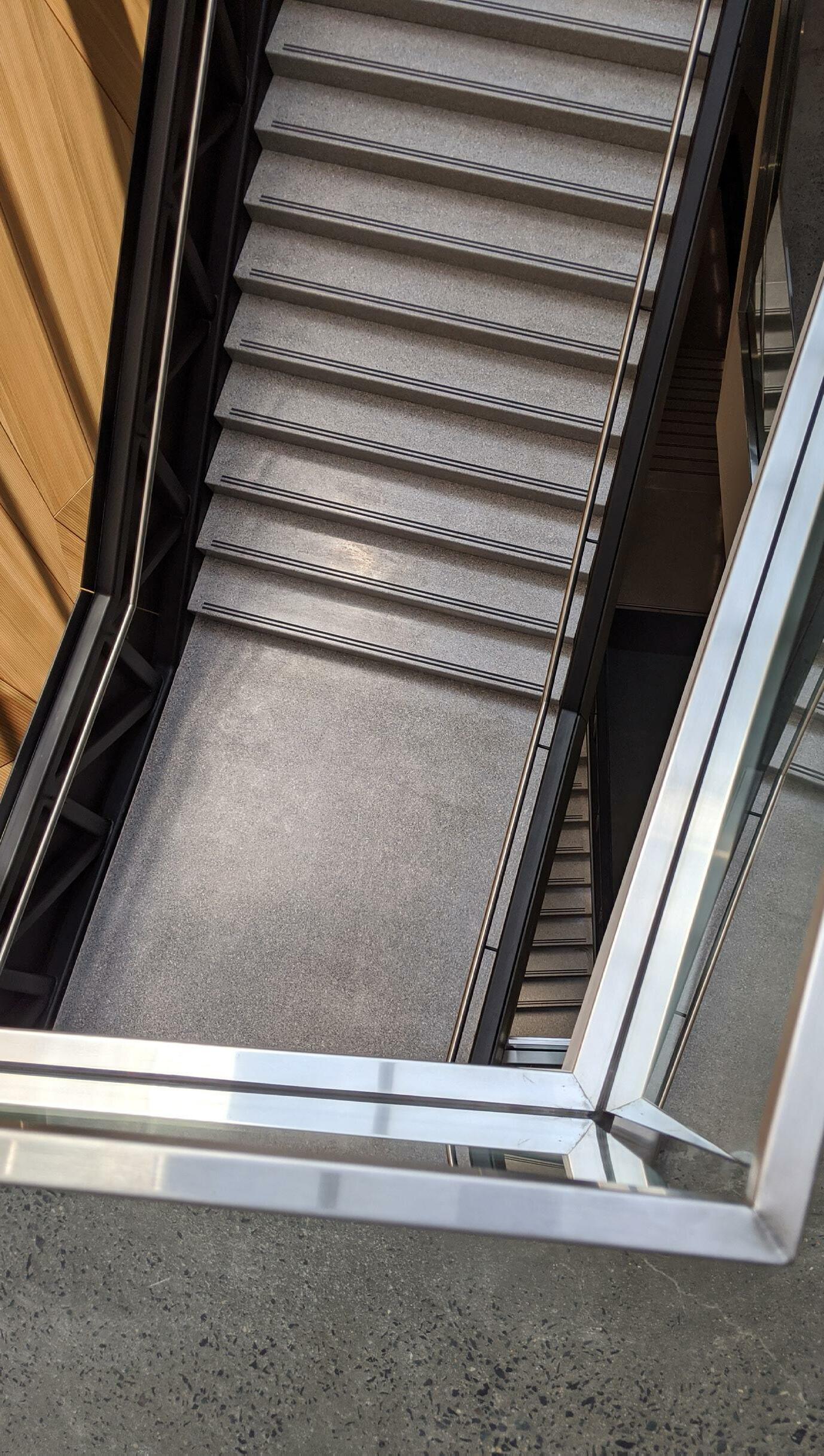
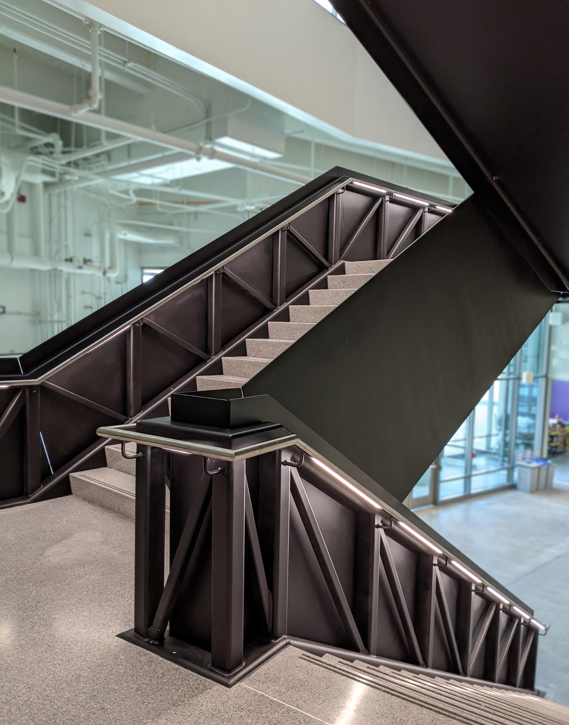
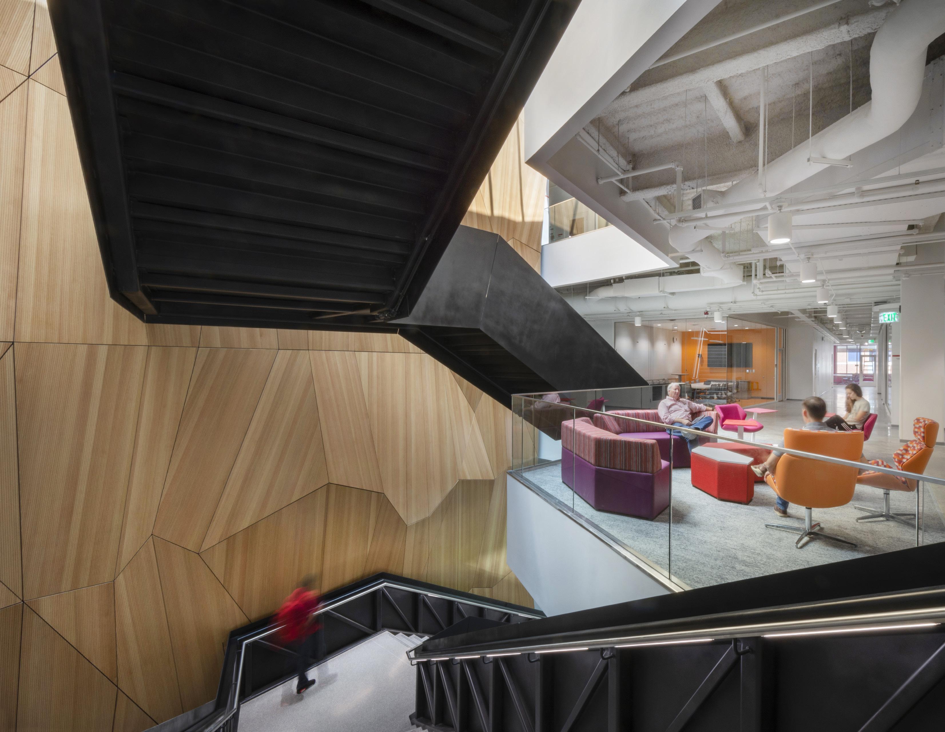
Fitts-Woolard Hall is home to NC State University’s structural engineering department. The design is driven by a commitment to “engineering on display.” Throughout the four-story facility, high degrees of transparency create a light-filled, vibrant education environment. Engineering on display is evident beyond educational spaces, as well. Throughout the facility, structural and mechanical building systems are revealed as an additional instructional tool. This commitment to transparency in all aspects of design emphasizes the cutting-edge research and education occurring within. The steel-plated monumental stair acts as a connecting thread between all four floors. Its path weaves upward alongside a feature wall designed to reflect the diverse engineering studies housed in the building. Its form not only creates a variety of gathering and collaboration spaces, but also expresses the structural stresses in the stairs via a large exposed truss.
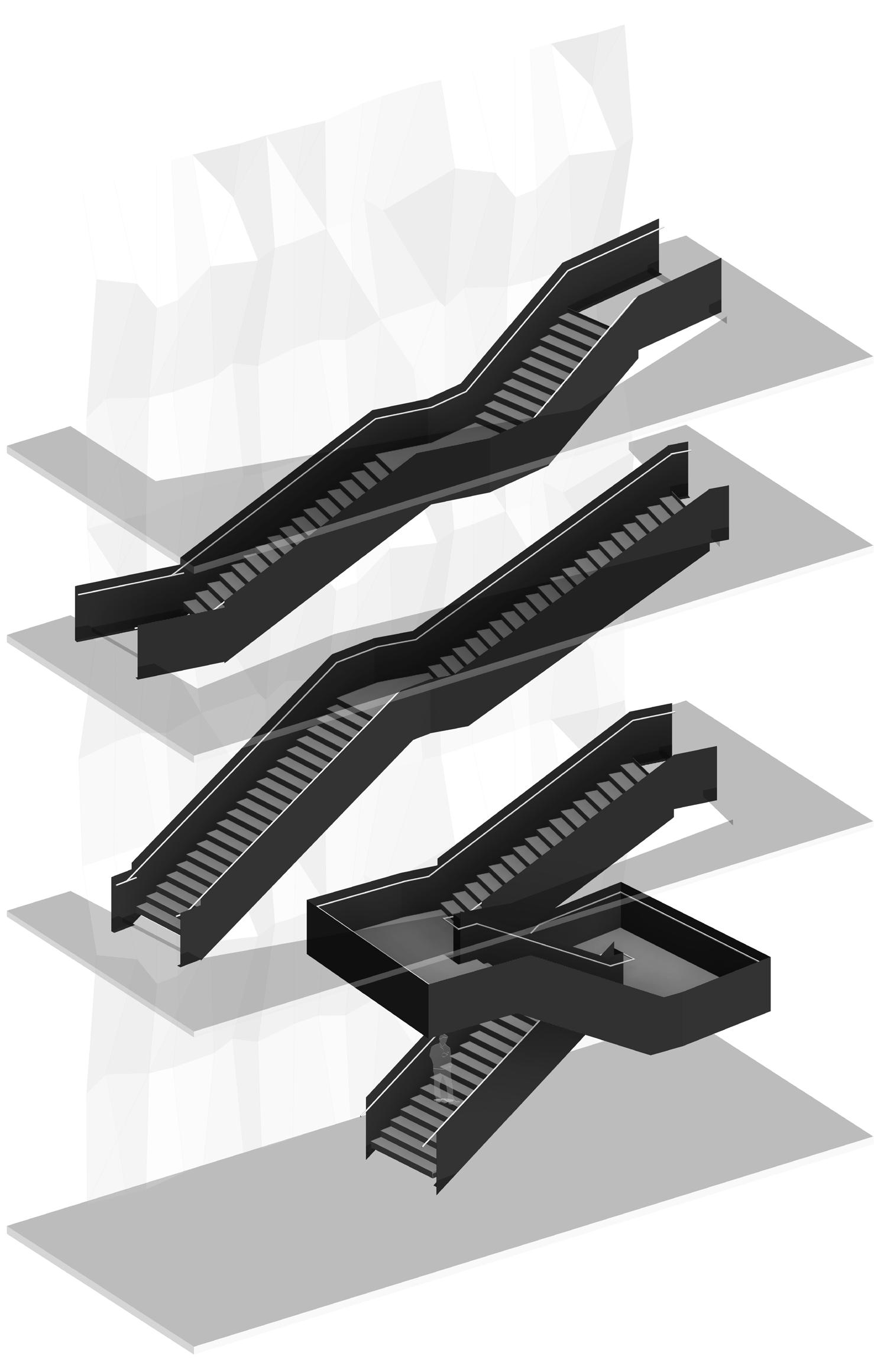
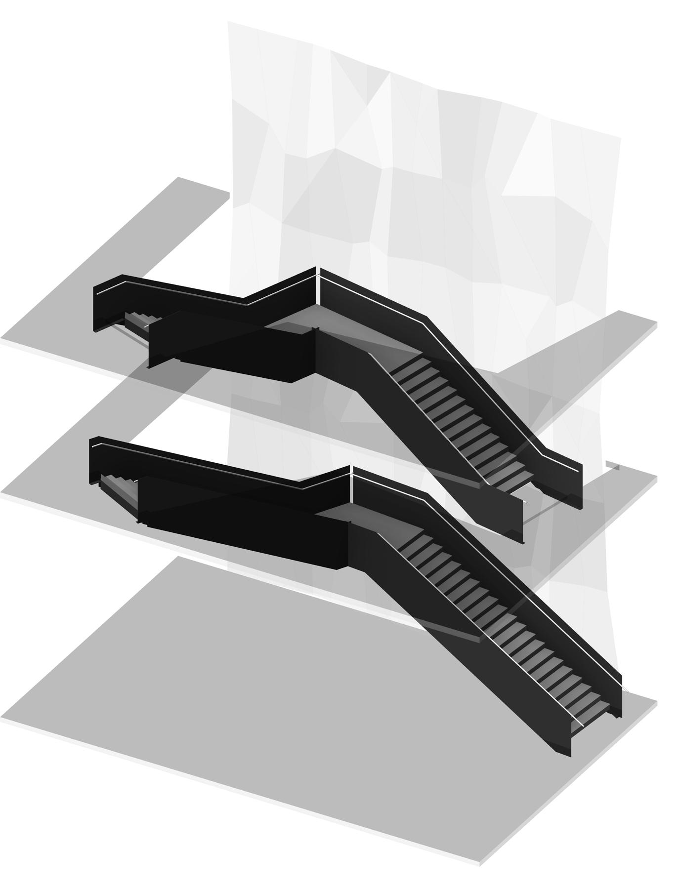
After the successful Go[Shelter] test case, the workflow was applied to the design of the monumental stairs at FittsWoolard. There are 5 unique sets of stairs, all configured differently, bending to maximize the penetration of the sunlight from the skylight at the top of each run.
The workflow proved to be essential to the success of this project. In the first step, the rigor of which the stairs needed to be modeled identified several dimensional issues that would have resulted in conditions where the guardrail or handrail would not have vertically aligned.
Since the architect was modeling this parametrically, it could quickly and easily be fixed and visualized to confirm that the design intent was being met.
The engineer used the old workflow for 2 of the stairs and a version of the proposed process for the remaining 3. Since this was the first time using the process, a hybrid approach to the workflow was implemented where the complex form and geometry were pulled in utilizing the workflow. Elements were then manually revised and changed by the engineer in RISA.
The engineer stated that the new process saved around a day of time for the more simple stairs, and around 3 days of time for the winding stair. An estimated 7 days of time would have been saved if the process was used on all 5 stairs. Later on it was even identified that one of the manually input stairs offset the members on the wrong side of the reference line, resulting in a stair that was 6” too narrow and needed to be fixed.
12
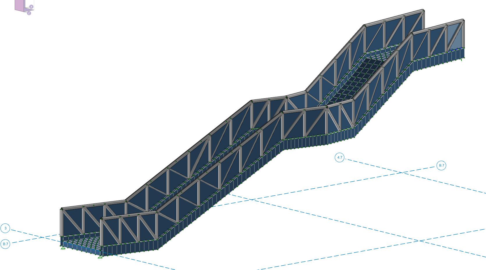
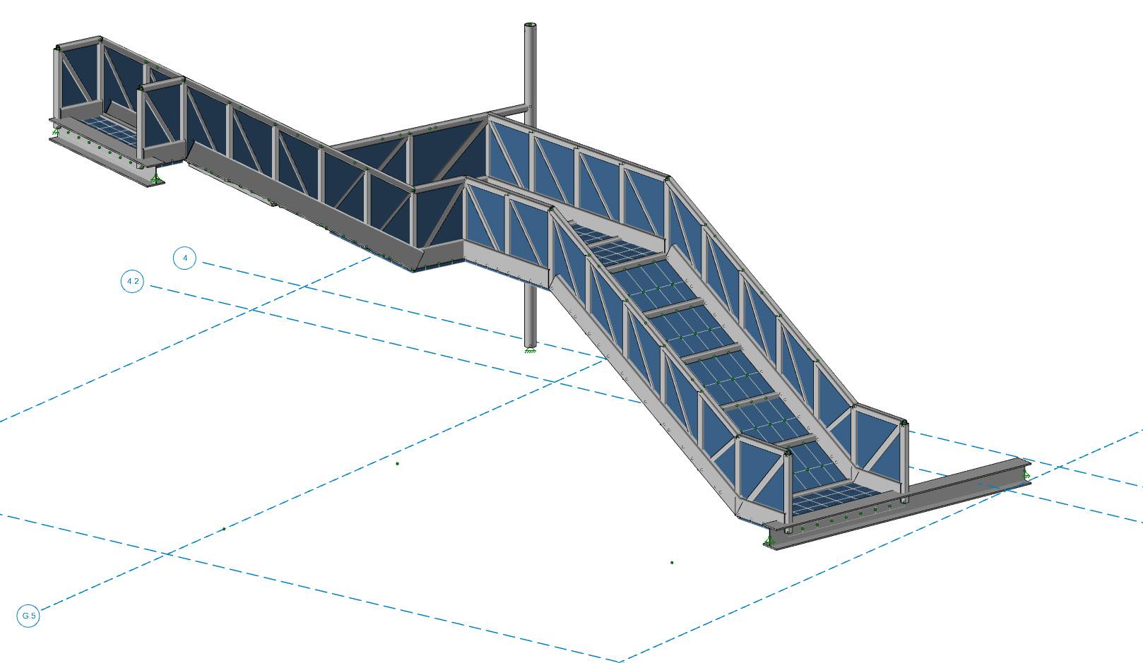
Each of the 5 monumental stairs has unique geometry and supports adding to the complexity of structural analysis. The new workflow proved to streamline the process, save time, and reduce error.
13
 The varying sized truss diagonal members and the complex geometry
The layering of the multiple nonorthogonal stair geometries.
The varying sized truss diagonal members and the complex geometry
The layering of the multiple nonorthogonal stair geometries.
14
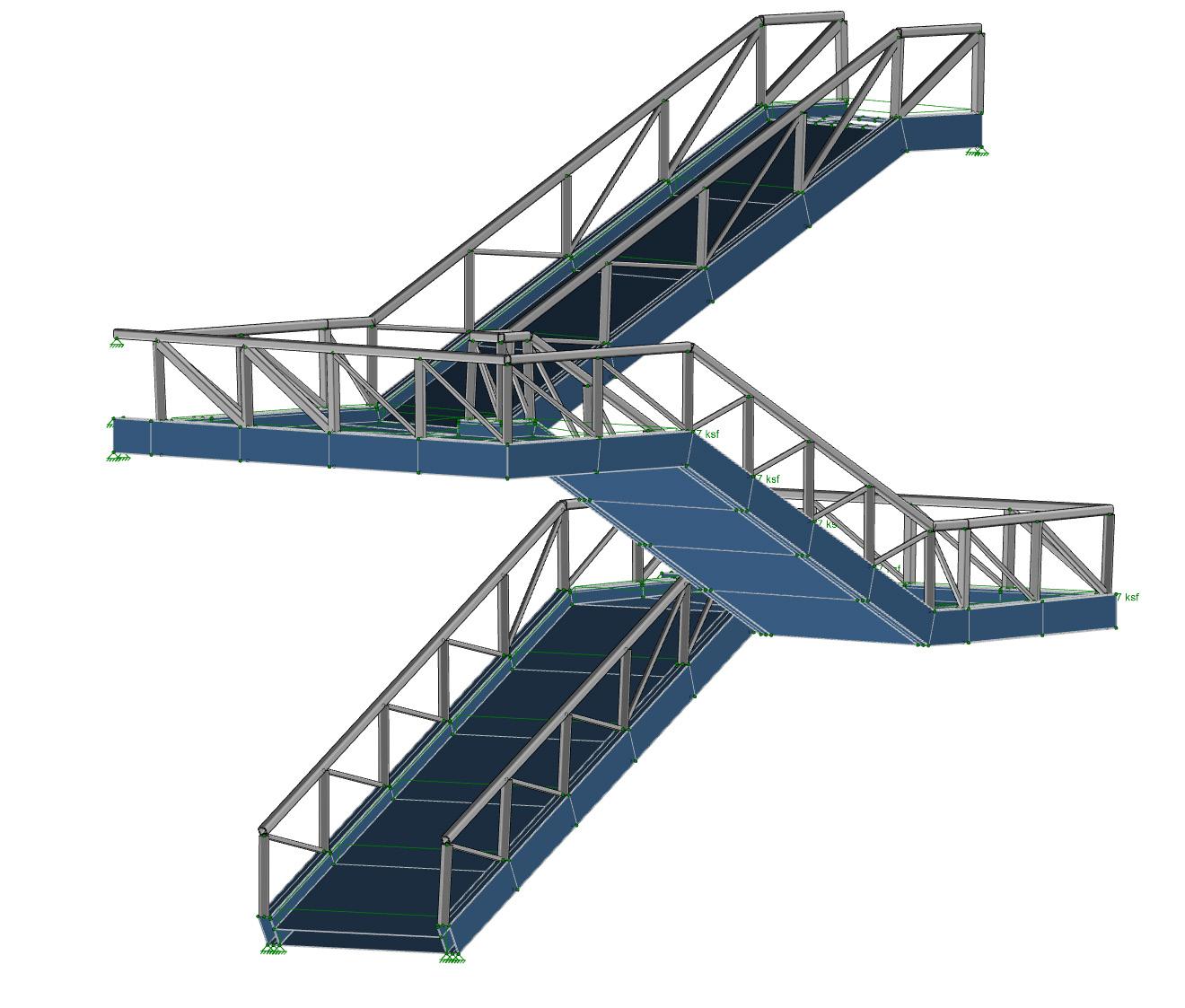
The Structural engineer modeled Stair 1 [Left] and 2 using the old process that took an estimated day extra to model compared to the proposed workflow. The main difference in the old and proposed process is that the bottom stringer is modeled as a ‘member’ instead of a series of ‘plates’.
The Structural engineer modeled stairs 3 [Left], 4, and 5 with a hybrid process that included both the automated geometry from the workflow as well as manually modeled elements
15
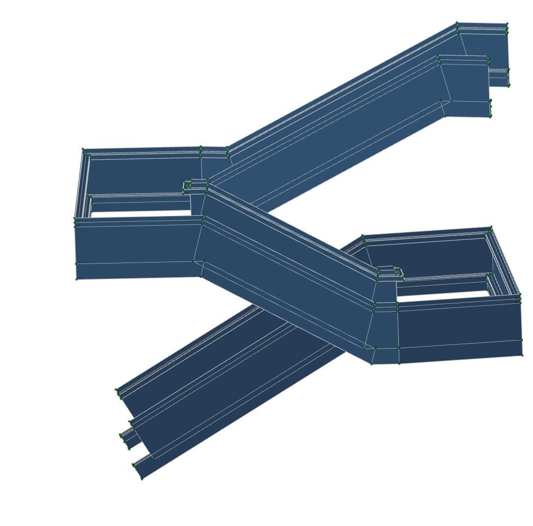
The Architect modeled the stairs parametrically. This allowed the use of a profile curve [Left] that represented the structural members sizes and locations, and a perimeter curve [Middle] that represents the stair. The resulting form [Right] was exported for analysis. Since the model was done parametrically, the form and the structural members could rapidly be changed, reviewed aesthetically, and re-exported.
Architect

The imported geometry from the proposed process [Right] was modified that aided the hybrid modeling approach used by the engineer [Left]. The upper geometry guided the placement of members and truss elements. The bottom ‘plates’ remained as imported.
+ =
Engineer
Profile curves of the structural members Perimeter curve of the stair
Resulting stair geometry
Geometry as imported in RISA
Final hybrid RISA model
Plates as imported
Truss elements modeled using import geometry as a guide
16
Graveyard of the Atlantic Museum Wave Structure
Design Concept
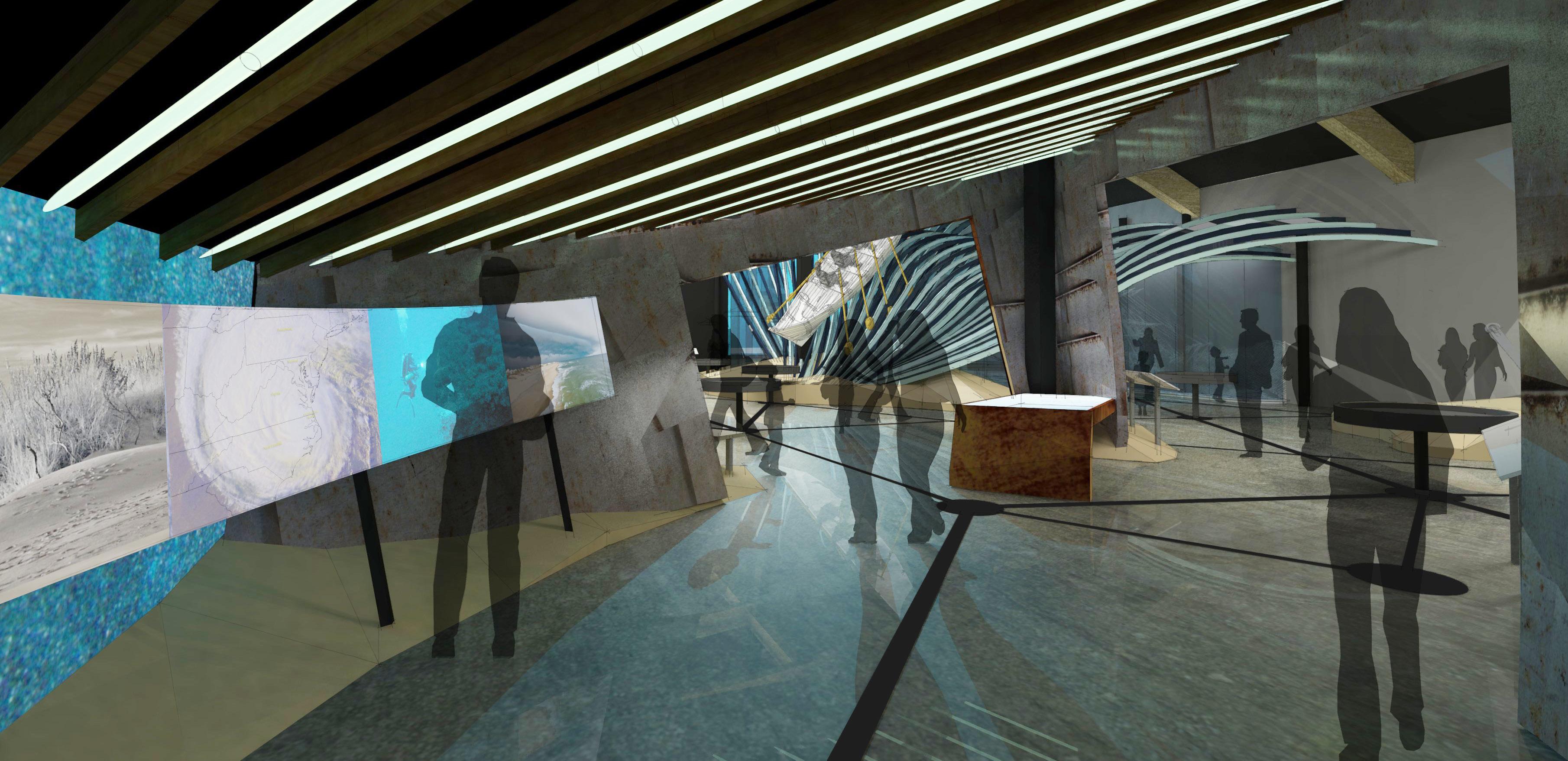
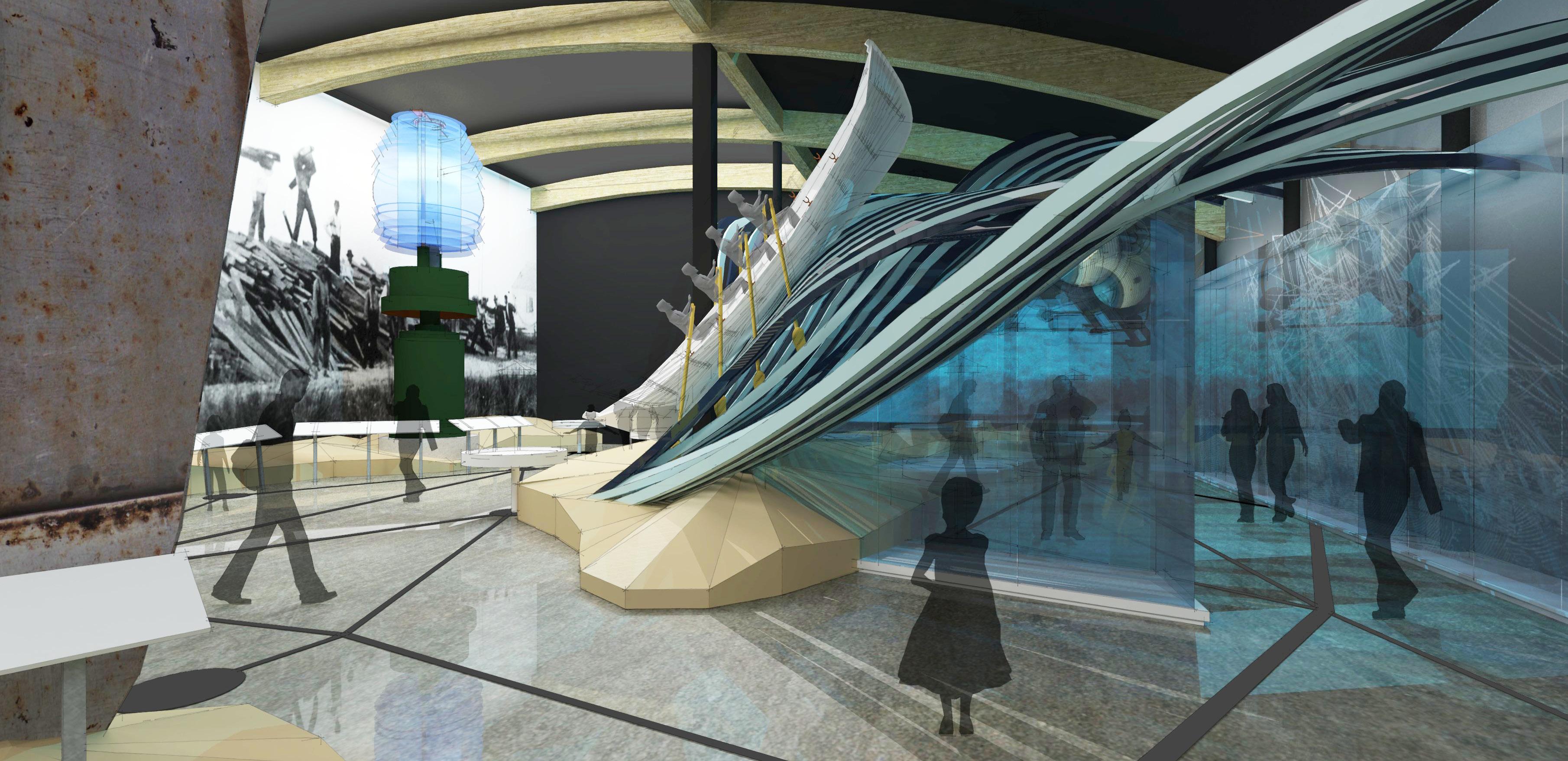
VIEW #4
The North Graveyard of the Atlantic Museum in Hatteras, NC is a 7,000 square foot exhibit including a large structural wave. The exhibits will highlight the thousands of vessels and mariners who lost a desperate struggle against the forces of war, piracy and nature off the North Carolina Coast. The exhibits will immerse visitors through scale, environmental graphics, and sound. North Carolina’s unique maritime history will be further emphasized through interactive experiences that reveal artifacts, preservation techniques, weather prediction technologies and modern lifesaving tools.
The third use of the process was for a wave structure for a museum installation that not only had to support its own weight, but also the weight of a full size boat with mannequins. The design is composed of 70 unique ribs all which needed to be analyzed structurally. The engineer knew that modeling this using the old workflow would be nearly impossible. Using the new workflow, the engineer was able to use the geometry provided by the designer and have the model ready for analysis in minutes instead of days.
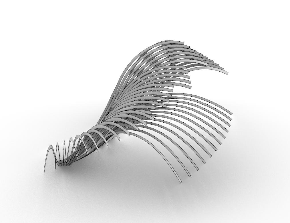
Using the script, the design team was able to simplify the curving form into facets that would allow for faster analysis, but not impact the results.
This project is still in design.
19
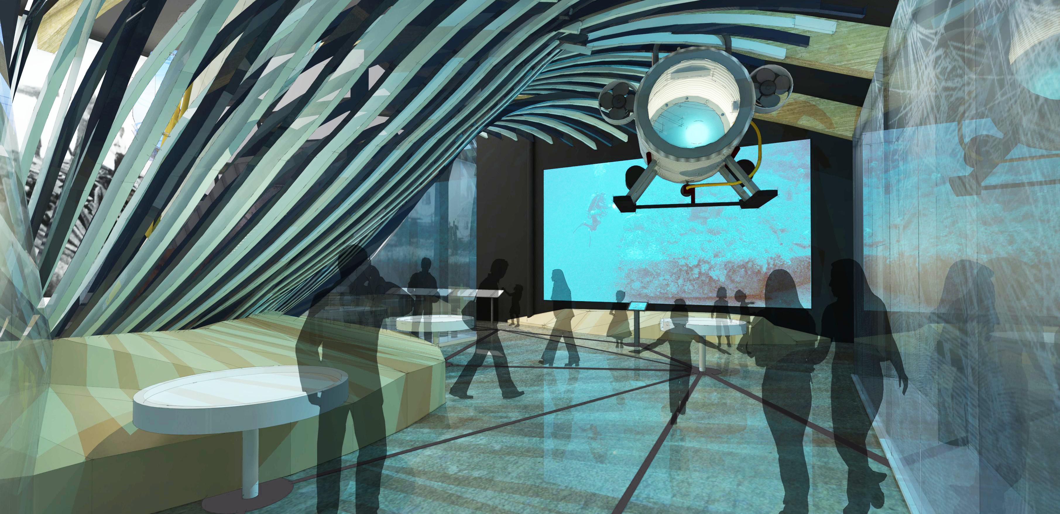
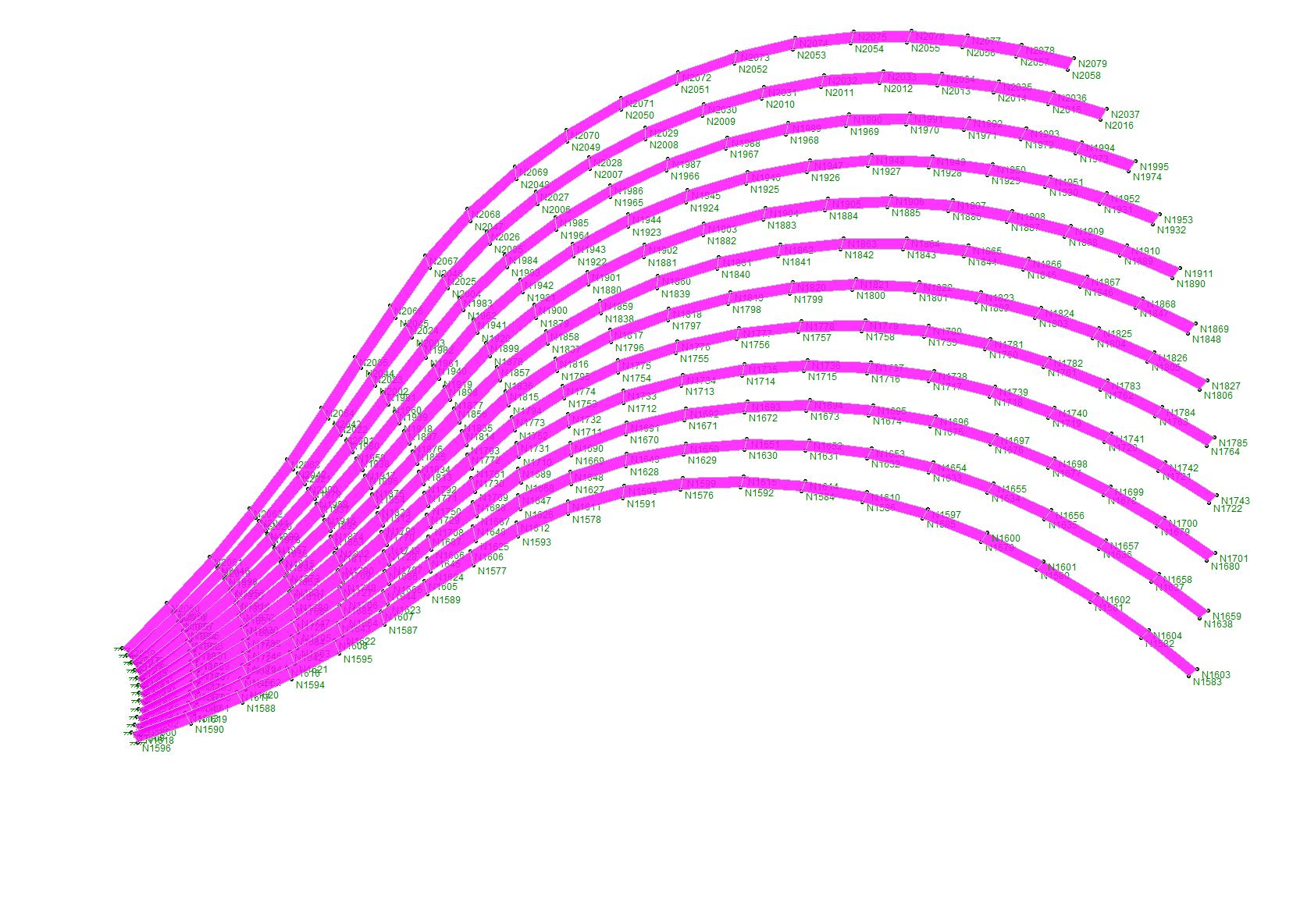
VIEW #5 Plan view showing all 70 unique ribs 3D View from underneath the wave 20
3d view of the design model showing the smooth curving forms
21
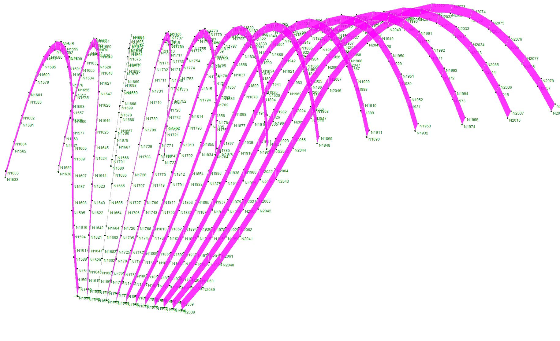
For ease of analysis, each rib was faceted , and each fan was broken out into its own RISA model. This fan has 504 unique points and 240 panels.

22
23
Part 3: Future
In the exploration of this workflow and observing the practical usage on real project workflows and timelines, several next steps have been identified for how the workflow can be improved and refined.
Engineering side:
NEW LIBRARY BUILDING
1533 SOUTH MAIN STREET WINSTON-SALEM, NC 27127
SCO ID# 06-06981-05A
steel, typ. re structural documents. coat with high performance coating.
edge of slab centerline of steel
THE


curtainwall mullion steel, typ. re structural documents. coat with high performance coating. airfoil, typ. re elevations for sizes, locations, and spacing typ.
align airfoil with centerline of vertical steel, typ.
IS NOT FOR BIDDING, PROCUREMENT, PERMIT OR CONSTRUCTION PURPOSES.
4 A10.6 2'-11"
7 1/2" 1 1/32" e d g e o f s l a b t o f a c e o f t u b e 3 7 1 7 / 3 2
In observing how the engineers use a hybrid approach of manual and automated geometry creation, the gains in efficiency are not fully realized. So the feedback loop is not as short as it should be. The engineers detailed workflow should be studied to establish their full workflow and points of validation that they require. The immediate steps are to automate the use of structural members (in lieu of or in addition to the plates) into the automated workflow. The second step would be to study the placement of loading in RISA to see if it can remain constant or adaptable when the underlying geometry changes based on the feedback loop. This includes studying the possibility of automating the placement of loading from inside the design model.
centerline of steel
4"
steel, typ. re structural documents. coat with high performance coating.
Design side:
3/8" airfoil attachment bracket WITH fluoropolymer COATING.
1/4" neoprene spacer countersink screws
align centerline of airfoil with centerline of vertical steel, typ.
8 1/4" 1'-4 1/2" 8 1/4" 1'-4 1/2" 1'-4 1/2" 1 5 2 3 / 3 2
FAYETTEVILLE STREET SUITE
RALEIGH,
A10.6 2A10.6 3
aluminum airfoil. 1/8" wall thickness WITH fluoropolymer COATING.
1/8" radius ends
slot edge of airfoil to recieve attachment bracket. re: section details
countersink airfoil attachment screws, typ. internal support for attachment1/4" weep holes.
10°
1 7 / 8
1/4" neoprene spacer countersink screws 1/4" weep holes.
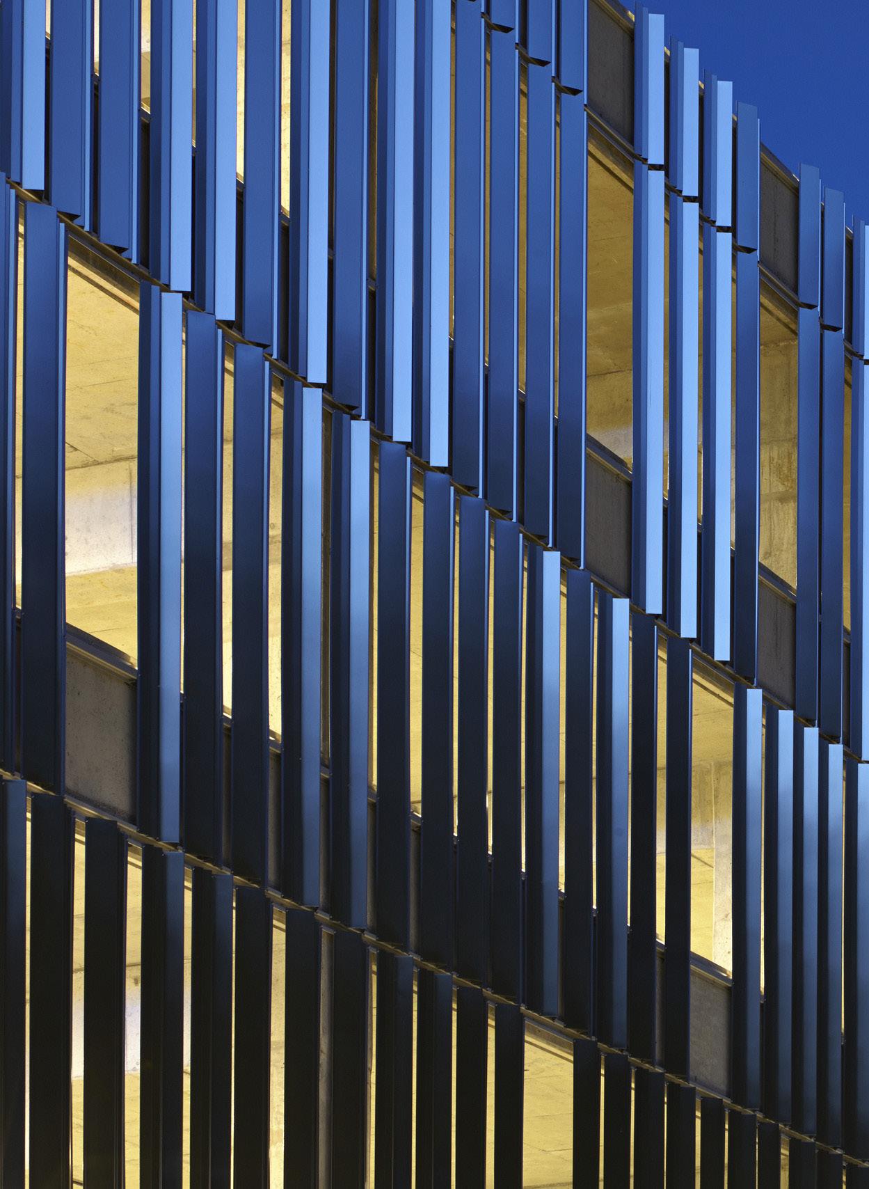
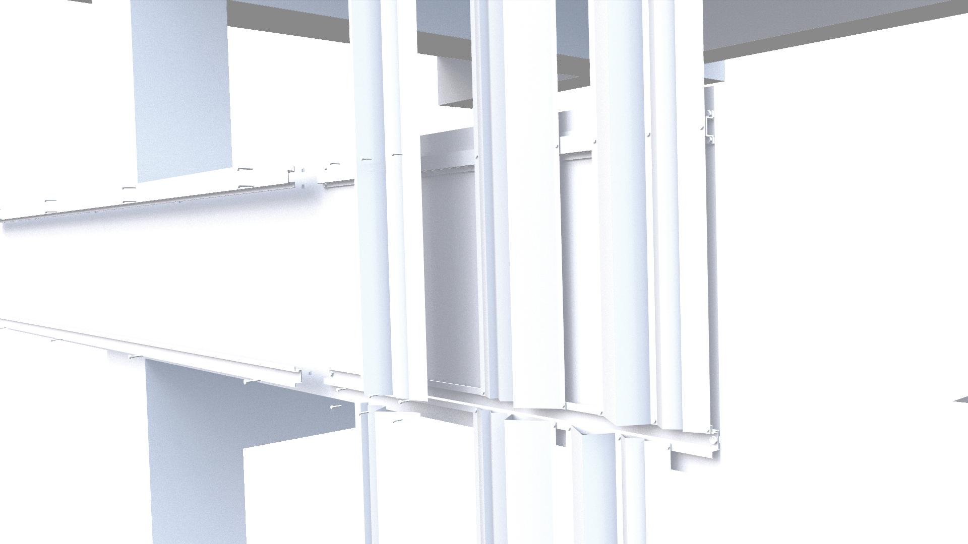
Looking back at previous projects inside the firm, several ideas arose about how the workflow could be used for facade design. In the examples shown to the left, these facades could utilize the workflow to speed up the process. With a faster more iterative process, strategies for reducing the embodied carbon that is in the structural elements could be studied. For example with facade elements, we could use the rapid process to compare the energy savings the shading provides compared to the embodied carbon in the shading structure and elements. Another step would be to test the feasibility of modeling the geometry using revit structural framing elements. Then, using Dynamo, import the structural members directly into RISA using the same process as the points and plates.
3/8" airfoil attachment bracket WITH fluoropolymer COATING.
1 ' 6" centerline of airfoil
aluminum airfoil. 1/8" wall thickness WITH fluoropolymer COATING.
1/8" RADIUS ENDS high performance steel tube, neoprene spacer galvanized galvanized tapping screw perforated steel metal 3/4" = 1'-0" 1 Airfoil - Typ Plan Detail 3" = 1'-0" 2 Airfoil Typical Attachment @ Vertical Members & Typ Deep Airfoil 3" = 1'-0" 3 Airfoil - Typ Horizontal airfoil support steel airfoil attachment bracket Level 2 15' 4" ROOF (AREA A) 70' - 10" Level 3 30' 8" Level 4 46' 0" smokestopping and fireproofing at each floor, typ per ul# cw-d-2042 zinc reveal panel soffit on 4" metal studs with AIR/VAPOR BARRIER ON exterior sheathing metal stud at 16" o.c. exterior sheathing reveal wall panel system roofing system see a6 series zinc EDGE COPING to match facade panels metal decking see structural typical soffit: exterior gwb, ptd on 3 5/8" metal studs @ 24" o.c. with 1/2" exterior FIXED VERTICAL SUNSCREEN, typ M I N 3 C O U R S E S Thermal and Air Barrier system, see specs 1" insulated glazing typ 8 " 8 " 8 typical soffit: 5/8" exterior gwb, ptd on 3 5/8" metal studs @ 24" o.c. with 1/2" sheathing, air/vapor barrier and batt insulation column beyond typ 8 " 8 HIGH PERFORMANCE painted steel screen rigging, typ see structural 8 1 0 0 " 1 1 4 aluminum column and beam covers beyond 1 6 0 " 1 0 0 A6.3 5 typ A10.11 26 Sim A10.6 4 Sim A10.11 29 Sim 1 9 9 2 0 0 8 1 1 2 1 1 2 " 8 1 1 4 FACE, TYP 1'-0" TO FINISH A7.6 7 A7.6 7 SIM A7.6 10 A7.6 10 A7.6 10 SIM ALIGN OPP HAND OPP HAND CORRIDOR 2104 CORRIDOR 3102 CORRIDOR 4102 continuous metal cap siliconed to reveal in column cover horizontal joint in column cover horizontal joint in column cover 3 8 " aluminum curtainwall system, typ smokestopping and fireproofing at each floor, typ per ul# cw-d-2042 smokestopping and fireproofing at each floor, typ per ul# cw-d-2042 wood paneling 1/2" reveal, typ CP N O BARBIERI&GIBSOWENNEXSEN, K R ALC CHARLOTTE N.C. CERT NO. N O T CORPORA TECTURALARCH TERED S G E R NORTH CAROLNA 50680 REG ETER ORTH S N I CHD AR L NA ECT ARO TDENNS I ST A E R IN C 5460 L E NG H ALL GS SEA S SUBM TTA ARCH TECT CONSULTANT Owner Project Identification 35 channel center street, suite 103 Boston, MA 02210 p (617) 350-3005 f (617) 350-6006 333
1000
NC 27601 919.836.9751 FAX 919.836.1751 WWW.CLARKNEXSEN.COM
INFORMATION CONTAINED ON THIS DRAWING, OTHER THAN CHANGES MADE BY CLARK NEXSEN, ORIGINATED FROM SOURCES OTHER THAN THE DESIGN PROFESSIONAL AND CLARK NEXSEN DOES NOT WARRANT OR REPRESENT THAT SUCH INFORMATION IS ACCURATE OR REPRESENTS THE ORIGINAL DESIGN AS CONTAINED IN THE CONTRACT DOCUMENTS. THIS DRAWING
CODE # 40638 ITEM # 301 RECORD DOCUMENTS 05 OCTOBER 2015 05 NOVEMBER 2012
LEVEL P1 344'-0" LEVEL P2 354'-0" GH LEVEL P3 366'-0" F.7 CW-09 CW-08 CW-07 Generator, N.I.C Silencer, N.I.C 8" cmu wall, typ 8" 6'-8" 2'-1" 5'-2" 9'-10" 6'-9" A10.5 A10.5 A10.5 1'-4 1/2" Neoprene spacer Aluminum clip angle w/ slotted connections (Re STRUCTURAL DOCUMENTS) Anchor in slotted hole, re: structural documents Edge of CONCRETE STRUCTURE Re: a2 series sheets for FIN spacing and locations re: structural documents for all connections MOUNTING CLIP BY FIN MANUFACTURER Vertical aluminum fin Continuous aluminum channel (Re STRUCTURAL DOCUMENTS) t.o.s. 3/4" above adjacent ffe 1/4" varies re: structural documents 8" 3/4" 7/8" Re: a2 series sheets for FIN spacing and locations re: structural documents for all connections MOUNTING CLIP BY FIN MANUFACTURER Vertical aluminum fin, typ 1" Aluminum cover plate @ ends of fins, typ Neoprene spacer Aluminum clip angle w/ slotted connections (Re STRUCTURAL DOCUMENTS) Anchor in slotted hole, re: structural documents Edge of CONCRETE STRUCTURE Continuous aluminum channel (Re STRUCTURAL DOCUMENTS) re: structural documents 8" 3/4" 7/8" varies1/4" t.o.s. 3'-1 1/2" Above adjacent FFE 1 CAST IN PLACE CONCRETE BEAM, RE: STRUCTURAL DOCUMENTS Extruded aluminum vertical fin, TYP. A6.1 5 A6.1 4 Level p4-8 COL 3'-1 1/2" 4 3/4" PROVIDE HIGH PERFORMANCE COATING FOR EXPOSED EXTERIOR face of concrete structure, typ R CAST IN PLACE CONCRETE BEAM, RE: STRUCTURAL DOCUMENTS Extruded aluminum vertical fin, TYP. 4'-7 1/2" 3/4" 3'-2 1/2" 7" Level p8-9 A6.1 5 Aluminum cover plate @ ends of fins, typ A6.1 5 col PROVIDE HIGH PERFORMANCE COATING FOR EXPOSED EXTERIOR face of concrete structure, typ sim LEVEL P2 354'-0" 6.1 LEVEL P3 366'-0" Rainwater irrigation hose access panel, alt #3 CAST IN PLACE CONCRETE BEAM, RE: STRUCTURAL DOCUMENTS CAST IN PLACE CONCRETE COLUMN, RE: STRUCTURAL DOCUMENTS PRECAST CONCRETE PANEL, TYP.3'-0" 4'-0" A6.1 A6.1 4 sim 3'-10 1/2" 1 CAST IN PLACE CONCRETE BEAM, RE: STRUCTURAL DOCUMENTS Extruded aluminum vertical fin, TYP. A6.1 A6.1 PROVIDE HIGH PERFORMANCE COATING FOR EXPOSED EXTERIOR face of concrete structure, typ col 3'-3 1/2" 7" 3'-1 1/2" 4 3/4" Level p3 GREEN SQUARE PARKING PEARCE BRINKLEY CEASE + LEE 333 FAYETTEVILLE STREET SUITE 1000 RALEIGH, NORTH CAROLINA 27602 TEL:919.836.9751 FAX:919.836.1751 THESE DRAWINGS REFLECT INFORMATION PROVIDED BY THE GENERAL CONTRACTOR. FIELD VERIFICATION OF THESE CONDITIONS HAS NOT BEEN CONFIRMED BY ARCHITECT. RECORD DRAWINGS: 08.01.11 PBC L + CERT. NO. E L R E ASE P S C O D # 6 C 6 7 4 1 0 1 B 4404 HES R AS R R N RECORD DRAWINGS 9/22/2011 4:38:49 PM Raleigh, NC A6.1 1467 MISC SECTIONS Department of Administration Parking DeckGreen Square 1 4 6 7 3/16" = 1'-0" 1 generator room sect on 6" = 1'-0" 5 Sect on Detail @ f n connect on 6" = 1'-0" 4 Sect on Detail @ f n jo nts 3/4" = 1'-0" 6 typ vert cal f n connection deta l @ levels p4 p8 3/4" = 1'-0" 2 typ vert cal f n connection deta l @ P8 P9 1/2" 1'-0" 3 wall sect on @ access panel 3/4" = 1'-0" 7 typ vert cal f n connection deta l @ level p3 PROVIDE HIGH PERFORMANCE COATING FOR EXPOSED EXTERIOR face of concrete structure, typ Examples of past projects facades that are good candidates for testing the modeling of facade elements using the proposed workflow. 25
Team and Project Credits
Case Study Project Team CreditsTeam Members
Ryan Johnson: Clark Nexsen
Architect, Computational Designer
Yichen Wei : Clark Nexsen
Computational Designer
Klaus Perkins: Clark Nexsen
Structural Engineer
Bus Shelter
Architect: Clark Nexsen Engineer - Structural: Clark Nexsen Contractor - Fabricator: South Eastern Architectural Services
Fitts-Woolard Hall
Architect: Clark Nexsen Computational Design: Clark Nexsen Engineer - Structural: Clark Nexsen Contractor: Skanska USA
Graveyard of the Atlantic Exhibit Designer: Riggs Ward Engineer - Structural: Clark Nexsen Computational Design: Clark Nexsen
26
CNCPT – Clark Nexsen Creative Practice Technology – is a com prehensive resource for practice technology in the firm, from better visualization to optimized workflows. Capitalizing on the intersection between design and technology, we apply advanced digital tools across our interdisciplinary practice to improve the quality and efficiency of our work and help clients make informed decisions. Our seven innovation hubs enable us to push the en velope – leveraging tools such as computational design and data visualization to solve complex challenges for our clients
Learn more at clarknexsen.com/cncpt/
CNCPT is the engine behind Clark Nexsen’s investigation and application of technologies that augment the design process.
27
