


This page intentionally left blank.

This page intentionally left blank.
Organisation: Connectus
Document Title: Erosion and Sediment Control Plan
Fulcrum Document Number: CRL-PAT-ENV-CON-PLN-000897
Document based on MMS No: n/a
Client: Auckland Transport
Project: CRL Enabling Works: Contract Two
Location: Auckland CBD Project No: 2665
This document remains the property of Connectus. Its contents are confidential and shall not be reproduced, destroyed or given away without the express, written permission of Connects. The electronic version of this document in MMS Database on designated server(s) is the Master Copy and is a controlled document. Unless specifically noted thereon, other copies of this document are uncontrolled.
This page intentionally left blank.
Term Definition
ACZ Active Construction Zone
AC Auckland Council
AT Auckland Transport
CEMP Construction Environmental Management Plan
CFA Continuous Flight Auger
CR City Rail Link
CSA Construction Support Area
CTMP Chemical Treatment Management Plan
EMP Environmental Management Plan
ESCP Erosion and Sediment Control Plan
ISCA Infrastructure Sustainability Council of Australia
pH Numerical measure of the acidity or alkalinity of a solution measured on a logarithmic scale on which 7 is neutral
TP90 Auckland Council Technical Publication 90 (TP90) “Erosion and sediment control guidelines for land disturbing activities in the Auckland Region”.
TSS Total Suspended Solids
WTP Water Treatment Plant
This page intentionally left blank.
4.4.3
Connectus
Project #: 2665
Client: Auckland Transport
Erosion and Sediment Control Plan
Doc. No. CRL-PAT-ENV-CON-PLN-000897
Revision: 04, Date: 21 March 2016
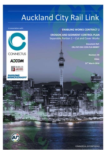
The City Rail Link (CRL) project comprises the construction, operation and maintenance of a 3.4 km underground passenger railway, running between Britomart Station and the North Auckland Rail Line in the vicinity of Mt Eden station. The works relating to this Erosion and Sediment Control Plan (ESCP) constitute part of the enabling works for the CRL. The works (the Project) involve the construction of twin rail tunnels within the Albert Street road corridor from Customs Street West to Wyndham Street. The tunnels will be constructed using a staged cut and cover method and are expected to take 33 months to complete. Figure 1 outlines the extent of works for the Project.
This ESCP (including a Chemical Treatment Management Plan (CTMP) – refer Appendix D) has been prepared by AECOM New Zealand Limited (AECOM) and forms part of the Construction Environmental Management Plan (CEMP) for the Project.
Project #: 2665
Client: Auckland Transport
Erosion and Sediment Control Plan
Doc. No. CRL-PAT-ENV-CON-PLN-000897
Revision: 04, Date: 21 March 2016
and Sediment Control Plan
Project #: 2665 Doc. No. CRL-PAT-ENV-CON-PLN-000897
Client: Auckland Transport
Revision: 04, Date: 21 March 2016
The objective of this ESCP is to provide for the management of all bulk earthworks to minimise any discharge of debris, soil, sediment or sediment-laden water beyond the site to land and stormwater drainage systems. The objective of the CTMP is to confirm the measures that will be taken to ensure that construction of the Project will be generally consistent with the Water Quality Assessment and the Industrial and Trade Activities Assessment prepared by Golder Associates (NZ) Limited, both dated December 2014
This ESCP and the CTMP will be implemented throughout the entire construction period and will be the primary tool for erosion and sediment control for the Project. They are ‘living documents’ which may undergo expansion and updates as the Project progresses and working conditions become clearer. Draft versions of the Plans were discussed with the AC monitoring team on Wednesday 2nd March 2016. Agreement on the general approach to sediment control was made during this meeting. It was also noted during the meeting that the choice of specific water treatment equipment may evolve from what is specified in this ESCP. However any change to the ESCP or CTMP will be submitted to Auckland Council (AC) (Team Leader Central Monitoring) for certification. No construction activity will commence until certification from AC is provided and no activity reliant upon a change to the ESCP or CTMP will be undertaken until the change has been certified.
This ESCP has been prepared in consultation with a Community Liaison Group (CLG) prior to submission to Auckland Council (as per condition 19 of the Britomart to Wyndham consent conditions). A record of these consultation outcomes is included in Appendix F.
Table 1 outlines the relevant conditions from land use consent R/REG/2014/5430 and how these are addressed within the ESCP.
Connectus
Project #: 2665
Client: Auckland Transport
Table 1 ESCP conditions from land use consent R/REG/2014/5430 and the relevant sections of this document
Erosion and Sediment Control Plan
Doc. No. CRL-PAT-ENV-CON-PLN-000897
Revision: 04, Date: 21 March 2016
44 This resource consent shall expire 15 years after the consent commences unless it has been surrendered or been cancelled at an earlier date pursuant to the RMA.
45 At least 20 working days prior to the commencement of construction, a finalised ESCP which provides for the management of all bulk earthworks to minimise any discharge of debris, soil, sediment or sediment-laden water beyond the site to either land and/ or stormwater drainage systems shall be prepared and submitted to the Council (Team Leader Central Monitoring) for certification
46 No construction activity shall commence until certification from Council is provided.
47 The Consent Holder shall request the Council’s (Team Leader Central Monitoring) determination as to whether the ESCP can be certified, in writing, within 10 working days of receipt of the ESCP.
48 The ESCP shall include, but not be limited to, the following matters:
a. identification of construction zones and construction support areas;
b. specific erosion and sediment control works for each Active Construction Zone (location, dimensions, capacity supporting calculations and design drawings), which should be in line with Industry Best Practice that will meet or exceed the performance of measures detailed in Auckland Council Technical Publication No. 90, Erosion & Sediment Control: Guidelines for Land Disturbing Activities in the Auckland Region (TP90);
c. catchment boundaries; 2.2
d. the timing and duration of construction and operation of control works (in relation to the staging and sequencing of bulk earthworks); 4
e. details relating to the management of exposed areas; 4
f. reference to the Chemical Treatment Management Plan and confirmation of ESC measures necessary to give effect to that plan; 4.4.3.3
g. reference to the Contaminated Soils Management Plan and confirmation of ESC measures necessary to give effect to that plan; and. 3.4.1
Project #: 2665
Client: Auckland Transport
h. monitoring and maintenance requirements, including information on complaint investigation and response procedures, training, and roles and responsibilities
49 Any change to the ESCP shall be submitted to the Council (Team Leader Central Monitoring) for certification. No activity reliant upon a change to the ESCP can be undertaken until the change has been certified. The Consent Holder shall request the Council’s (Team Leader Central Monitoring) determination as to whether the proposed change can be certified, in writing, within 10 working days of submission of the change.
50 At least 20 working days prior to the commencement of construction, a CTMP which confirms the measures that will be taken to ensure that construction of the Project or Project Stage will be generally consistent with the Water Quality Assessment and the Industrial and Trade Activities Assessment prepared by Golder Associates (NZ) Limited, both dated December 2014 shall be submitted to Council (Team Leader Central Monitoring) for certification.
51 The Consent Holder shall request the Council’s (Team Leader Central Monitoring) determination as to whether the CTMP can be certified, in writing, within 10 working days of receipt of the CTMP.
52 The CTMP shall include, but not be limited to, the following matters:
a. Specific design details of the chemical treatment system based on a batch dosing methodology for the site’s settlement tanks, including the potential for use of nonchemical flocculants (e.g. chitin based flocculants such as Haloklear);
b. Monitoring, maintenance (including post-storm) and contingency programme (including a record sheet);
c. Details of optimum dosage (including assumptions);
d. Results of initial chemical treatment trial;
e. A spill contingency plan; and
f. Details of the person or bodies that will hold responsibility for the long term operation and maintenance of the chemical treatment system and the organisational structure which will support this system.
04, Date: 21 March 2016
Appendix D
Appendix D
Appendix D
Appendix T of the Project CEMP (Emergency Spill Response Plan)
53 Any change to the CTMP shall be submitted to the Council (Team Leader Central Monitoring) for certification. No activity reliant upon a change to the CTMP can be undertaken until the change has been certified. The Consent Holder shall request the Council’s (Team Leader Central Monitoring) determination as to whether the proposed change can be certified, in writing, within 10 working days of 1.1
Project #: 2665
Client: Auckland Transport Revision: 04, Date: 21 March 2016
submission of the change.
54 Prior to construction (bulk earthworks) commencing, a certificate signed by a senior qualified person shall be submitted to the Council (Team Leader Central Monitoring) to certify that the erosion and sediment controls have been constructed in accordance with the certified ESCP(s) as required by Condition 45 of this consent.
55 Certified controls shall include diversion bunds, silt fences, and sumps. The certification for these subsequent measures shall be supplied immediately upon completion of construction of those measures. Information supplied, if applicable, shall include:
a. contributing catchment area;
b. shape of structure (dimensions of structure);
c. position of inlets/outlets; and
d. stabilisation of the structure.
56 The Consent Holder shall ensure that there shall be no deposition of earth, mud, dirt or other debris on any road or footpath resulting from bulk earthworks on the subject site. In the event that such deposition does occur, it shall immediately be removed. In no instance shall roads or footpaths be washed down with water without appropriate erosion and sediment control measures in place to prevent contamination of the stormwater drainage system, watercourses or receiving waters.
57 The operational effectiveness and efficiency of all erosion and sediment control measures specifically required as a condition of resource consent, including the certified ESCP referred to in Condition 45, shall be maintained throughout the duration of bulk earthworks, or until the Project site is permanently stabilised against erosion.
58 The site shall be progressively stabilised against erosion at all stages of earthworks activity, and shall be sequenced to minimise the discharge of contaminants to groundwater or surface water.
59 The Consent Holder shall ensure that the erosion and sediment control measures shall be constructed and maintained in accordance with Auckland Council’s Technical Publication 90: Erosion and Sediment Control Guidelines for Soil Disturbing Activities in the Auckland Region, and any amendments to this document, except where a higher standard is detailed in the documents referred to in conditions above, in which case the higher standard shall apply.
60 Sediment control measures shall be inspected on a weekly basis and after a significant storm event to ensure effective operation. In the event that a discharge of debris, soil, silt, sediment or sediment-laden water occurs, the activity which resulted in the discharge shall cease immediately and the discharge shall be mitigated and/or rectified to the satisfaction of the Council (Team Leader Central Monitoring).
Project #: 2665
Client: Auckland Transport Revision: 04, Date: 21 March 2016
61 The Consent Holder shall ensure that all material removed from or delivered to the Project site shall be covered during transportation. 3.3
62 Upon completion or abandonment of bulk earthworks on the Project site all areas of bare earth shall be permanently stabilised against erosion to the satisfaction of the Council (Team Leader Central Monitoring).
63 Pursuant to section 128 of the RMA the conditions of this consent may be reviewed by the Council (Team Leader Central Monitoring) at the Consent Holder’s cost, by giving notice pursuant to section 129 of the Act, within six months after commencement of bulk earthworks and subsequently at intervals of not less than one year thereafter in order to achieve the following:
a. To deal with any adverse effects on the environment which may arise or potentially arise from the exercise of this consent and which it is appropriate to deal with at a later stage;
b. To alter erosion and sediment control requirements as a result of previous monitoring outcomes, and/or in response to changes to the environment and/or hydro-geological knowledge, and/or changes to industry best practice;
c. If, at any time, it is found that the information made available to the Council in the application contained inaccuracies which materially influenced the decision and the effects of the exercise of the consent are such that it is necessary to apply more appropriate conditions; and
d. If, at any time, CRL-related works being undertaken under a designation providing for aspects of the Project, or a separate resource consent, leads to an inconsistent approach to the management of effects.
99
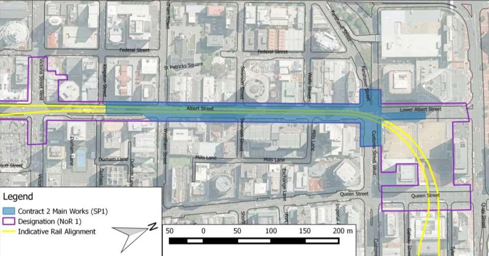
The Consent Holder shall ensure that the following structural controls are constructed for the following catchment areas and design requirements and they are completed prior to discharges commencing from the site.
3.1, 4.4, Appendix K of the CEMP (Industrial Trade Activities Environmental Management Plan)
Project #: 2665
Client: Auckland Transport Revision: 04, Date: 21 March 2016
100 In the event that any minor modifications to the structural controls system are required, the following information shall be provided to Council:
a. Plans and drawings outlining the details of the modifications; and
b. Supporting information that details how the proposal does not affect the capacity or performance of stormwater management system. All information shall be submitted to, and the proposed modifications certified by the Council (Team Leader Central Monitoring), prior to implementation.
101 Within 30 days of the installation of the water treatment system, and prior to operation, a discharge monitoring programme, to assess the ongoing adequacy of all management practices, shall be developed and submitted to the Council (Team Leader Central Monitoring) for certification. The monitoring programme shall include, but not be limited to:
a. sampling location for final discharge from the site(s);
b. sampling locations on site (i.e. swale inlets, outlets etc);
c. methods and procedures for discharge sampling on a quarterly basis;
d. monitoring parameters for analysis, which shall include:
Daily
· Turbidity (NTU)
· pH
Weekly
· Total Suspended Solids mg/L
· Copper (total) mg/L
· Zinc (total) mg/L
· Lead (total) mg/L
· Total Petroleum Hydrocarbons mg/L
e. identified trigger levels for each of the above parameters. These trigger levels shall be developed with reference to the ANZECC Guidelines for water quality where applicable; and
f. the methods and procedures for investigating and reporting stormwater discharge monitoring results to the Council (Team Leader Central Monitoring).
Project #: 2665
Client: Auckland Transport
Erosion and Sediment Control Plan
Doc. No. CRL-PAT-ENV-CON-PLN-000897
Revision: 04, Date: 21 March 2016
AT is seeking an Infrastructure Sustainability Council of Australia (ISCA) Infrastructure Sustainability (IS) rating for the Project. Full details are included in the Project’s Sustainability Management Plan. Project sustainability requirements that relate directly to the ESCP are included in Appendix E.
Project #: 2665
Client: Auckland Transport
Erosion and Sediment Control Plan
No. CRL-PAT-ENV-CON-PLN-000897
Revision: 04, Date: 21 March 2016
This section presents a summary of the Project in relation to the matters required to be addressed by the ESCP and CTMP. A detailed description of the construction works is provided in the CEMP.
Connectus will use a cut and cover method to construct two parallel rail tunnels within the Albert Street road corridor between Customs Street and Wyndham Street. The total length of the tunnel for the Project will be 340m. A number of utilities are required to be removed, relocated, or supported during construction.
Generally, the Project works will consist of:
1. Utilities relocation and exposure
2. Piling and capping beam construction within Albert Street (including relocating of any relevant services)
3. Piling and road deck construction within the Customs Street Intersection
4. Trench Excavation, including using shotcrete and rock-dowelling
5. Construction and waterproofing of the rail tunnels
6. Backfilling of the trench, including construction of the new road pavement.
2.1.1 Utilities relocation and exposure
The location of utility service cables/pipes/ducts (gas, electricity, phone, wastewater, stormwater) (herein collectively referred to as utilities) within the Project footprint have been identified through site inspections and liaison with Network Utility Operators, including Vector Electricity, Vector Gas, Vector Communications, Chorus, Auckland Council and Vodafone. It is not feasible to completely avoid all utilities, although wherever possible piling locations and other construction activities have been selected to avoid conflict with services. This CNV DWP covers only those utility works within the designation footprint and separate provision has been made for utility works required outside of the designation footprint.
Utility relocation works required for Project construction includes works both inside and outside of the trench alignment. All works outside of the trench will be completed prior to excavation works, while the works within the trench will be completed during trench excavation or as the trench is being backfilled on completion of tunnel construction.
Further detail on utilities relocation can be found in the Project CEMP.
2.1.2 Piling and capping beam construction within Albert Street
Piling is required as the initial stage of construction for the Project. It includes the installation of cased continuous flight auger (CFA) piles and the construction of pile caps. Figure 2 shows the location and staging of the piling (the sequence will be confirmed closer to construction). The asphalt surface of the road reserve will be removed and the utilities relocated. Piling will then occur, and a Pile-Cap constructed to connect the piles along the western side of Albert Street. Reinforcing will be installed and concrete placed.
2.1.2.1
Continuous steel traffic decks will be installed along each side of the main trench along Albert Street during the piling and capping stage of construction. The traffic deck along the western side of the
Project #: 2665
Client: Auckland Transport
Revision: 04, Date: 21 March 2016
trench will extend between Swanson Street and Customs Street, and will be used by general traffic along Albert Street. The traffic deck along the eastern side of the trench will extend between Wyndham Street and Customs Street and will be limited to use by construction traffic only. The eastern deck (construction traffic deck) will provide continuous access into the excavation along the length of the trench and additional construction site set down and plant space to supplement the southern and northern compounds. In addition to the continuous traffic decks, two pedestrian bridges will span the trench, located on the north side of the Wyndham Street and Swanson Street intersections.

Piling and construction of a deck structure at the Customs Street/Albert Street intersection will permit traffic to cross over, while tunnel construction occurs underneath. The deck will be constructed in four stages as shown in Figure 3. This will enable traffic to utilise the intersection during construction and avoids closing the intersection completely.
Each stage requires pile installation and jet-grouting followed by excavation to approx. 2m depth to allow the construction of the concrete deck. Once all four piling and deck sections are complete, excavation and tunnel construction can commence beneath the live intersection.
In addition to supporting the traffic deck, the piles and jet-grout columns hold back the soil during excavation beneath the deck and stop water from entering the excavation site. After tunnel construction the area under the deck will be backfilled, and the deck structure ‘buried’ (i.e. the deck will no longer be a separate deck structure and will be incorporated in the area immediately below the intersection pavement).
Erosion and Sediment Control Plan
Project #: 2665 Doc. No. CRL-PAT-ENV-CON-PLN-000897
Client: Auckland Transport
Revision: 04, Date: 21 March 2016
Figure 3 Staged construction of road deck - – sections of the deck will be constructed in 4 stages (sequentially)
Trench excavation will be carried out in layers (starting at the southern end) with installation of temporary struts and ground anchors as the depth increases.
As excavation progresses, steel waler beams and struts will be installed in combination with ground anchors to support the piled trench walls. In addition, shotcrete and/or rockfall mesh with pins will be applied to the sides of the trench to stabilise the excavation face. Shotcrete will be spray applied, Rockall mesh is installed by driving short pins into the soil and attaching the mesh to the pins.
As the trench becomes deeper, excavators and loaders will be located inside the trench to break material from the natural face of the trench and transport material to stockpiles. On the construction deck above, cranes and excavators will reach down to remove material from the trench to load onto trucks for offsite disposal.
The construction of the rail tunnels will be a rolling process with multiple work faces progressing simultaneously. The tunnel works will start at the southern end of Albert Street when the excavation plant is clear of the base of the tunnel.
Tunnel construction will be broken into 12m lengths, and comprises the following tasks:
- Base drainage and blinding
- Waterproofing
- Base foundation and construction
- Wall construction
- Roof construction
- Roof waterproofing
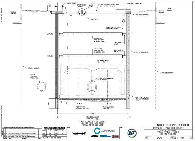
Figure 4 shows a typical cross section for the cut and cover tunnels.
Project #: 2665
Client: Auckland Transport
Revision: 04, Date: 21 March 2016
Concrete will be pumped to the works by pump machinery that is initially located at the compound on the southern side of Albert Street. The pump machinery is moved onto the construction deck as the works proceed further north.
Figure 4 Typical cross section for the Albert Street Cut and Cover Tunnels
As the construction of the tunnels progresses, back filling of the cut and cover excavation in the Custom Street Intersection and Albert Street trench will occur. The trench backfill will be placed on top of the tunnel structure after construction has been completed for a sufficient length (approximately 50m), including the installation of the waterproofing membrane, and will continue to follow the tunnel construction as it progresses. A layer of concrete blinding (or similar) will be placed over the roof membrane for protection from the trench backfill works. Material will be delivered to site by trucks on the construction deck. Trucks will deposit the fill material onto the floor of the deck structure and it will be collected and tipped into the trench by a loader.
Works to complete new utility routes or reinstate existing utilities will be co-ordinated with the filling operation as it reaches the upper layers. Finally, the construction of the new permanent road pavement will occur in stages after the trench backfill has been completed.
Where required in order to maintain traffic movements, it will be necessary to put down a temporary pavement. Temporary pavements will consist of unbound granular material with a bituminous seal, concrete panels or steel plates on the surface.
Erosion and Sediment Control Plan
Project #: 2665 Doc. No. CRL-PAT-ENV-CON-PLN-000897
Client: Auckland Transport
Revision: 04, Date: 21 March 2016
The Project works are comprised of Active Construction Zones (ACZ) D and E, which were identified during the consenting process for the CRL enabling works. These zones are described in more detail below and have been used to delineate the proposed construction methodology for different areas of work Table 2 describes the location of each ACZ:
*refer Appendix A for location of ACZ
ACZ D is the area where the Customs Street intersection piling and road deck construction is located while ACZ E is the length of Albert street where the piling and tunnel construction is located.
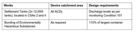
The Project makes use of the Construction Support Areas (CSA) identified during the consenting process, although the exact boundaries have been modified (Table 3). CSAs 4 and 6 are located at the northern and southern extent of the works respectively and will be used for the duration of the works. CSA 5 is located on the approaches to the Customs Street West/Albert Street intersection and will be used during the customs street piling and road deck construction CSA 5 will move during the four stages of road deck construction (refer Section 2.1.3 and Figure 3 of this ESCP). Once the road deck has been constructed, it will be opened to traffic and only parts of CSA 5 will be used as a CSA
Table 3 Construction Support Areas
6
*refer Appendix A for location of CSA
Details of each CSA are provided below.
CSA 6 – at the Southern end will provide for:
A small site office
A laydown area for materials and equipment
A small toilet and lunchroom facility
A generator
A load-in area for backfill material.
Concrete pumping equipment and concrete load-in.
Skip bins / rubbish and recycling bins
Provision for 150m³ of stockpiled material during the tunnel backfilling.
An earthworks storage area used for storing spoil during excavation and storing backfill material during backfilling
Project #: 2665
Client: Auckland Transport
CSA 4 – at the Northern end will provide for:
General and hazardous goods storage
Piling and deck equipment laydown
Skip bins / rubbish and recycling bins
Spill kits
Jet grouting equipment storage
A more substantial lunchroom and toilet facility
Site offices
A generator
Vehicle and Equipment Parking
Materials delivery and handling
Settling tanks
CSA 5 – On Customs Street:
Revision: 04, Date: 21 March 2016
CSA 5 will be a relatively fluid construction support area as the intention is to keep traffic lanes open through staged construction of a traffic deck. During deck piling and deck construction CSA 5 will be used for:
Piling equipment laydown
Jet grouting equipment
A Generator
Concrete delivery and pumping.
Portable toilet facilities
Skip bins / rubbish and recycling bins
Parking for the spoil removal truck
A bunded stockpiling area.
Once the bridge deck is complete, most of the area identified as CSA 5 during consenting will be open to traffic as works are carried out beneath the bridge.
Stormwater runoff from adjacent catchments will be controlled and managed throughout all construction works. Stormwater inflow rate into the trench excavation has been estimated based on the catchment area of the trench, which is calculated to be 3,700m2 (refer Appendix B of this ESCP).
Further detail regarding stormwater runoff management is provided in Section 4 of this ESCP.
The excavation work for trench construction will be located through fill material underlain by Tauranga Group sediments and East Coast Bays Formation residual soil and rock of various weathering grades
The Aurecon/PDP (2013) report highlighted key aspects of the hydrogeological regime including the following:
Groundwater within the reclamation fill (encountered at the northern end of the proposed trench excavation) occurs between 2m and 3 m below ground level with maximum tidal fluctuations in excess of 1 m.
Connectus
Project #: 2665
Client: Auckland Transport
Erosion and Sediment Control Plan
Doc. No. CRL-PAT-ENV-CON-PLN-000897
Revision: 04, Date: 21 March 2016
Regional groundwater beneath Albert Street occurs at depths greater than 18 m below ground level, which is shallower than the proposed rail tunnel alignment.
Perched groundwater beneath Albert Street is present in a series of interbedded sandstone/siltstone layers with relatively low permeability and limited lateral and vertical extent. Groundwater levels were measured at approximately 6 m below ground level (Golder 2014b).
Preliminary assessments have indicated maximum inflows into the trench of 16.4m3/day (refer to the Project Groundwater and Settlement Monitoring and Contingency Plan (GSMCP) in Appendix J of the Project CEMP). This number has been used for the purposes of sizing the treatment devices.
Project #: 2665
Client: Auckland Transport
Erosion and Sediment Control Plan
Doc. No. CRL-PAT-ENV-CON-PLN-000897
Revision: 04, Date: 21 March 2016
Erosion and sediment control measures will be set up to minimise the extent of soil erosion and sediment yield from the Project site during construction and will be implemented and monitored in accordance with Auckland Council Technical Publication 90 (TP90) “Erosion and sediment control guidelines for land disturbing activities in the Auckland Region”. Sediment laden water from the Project construction works during the trenching and rail tunnel construction phases will be treated to achieve the effluent quality goal was established in the Water Quality Assessment prepared by Golder Associates (NZ) Limited, dated December 2014. This identifies minimum water clarity for all discharges of 10cm or greater measured with a black disk, pH between 5 and 9, and no visible TPH. In some circumstances, and where appropriate, measures exceeding the requirements of TP90 will be used in order to meet the effluent quality goal. While Condition 99 of the Resource Consent specifies the use of structural controls as 2x 12,000L settlement tanks, developed design has resulted in a different approach to sediment control. For some work phases, the controls used will include the use of settlement tanks but other phases will apply different sediment controls as detailed below. General agreement on this approach was reached with the AC monitoring team in a meeting held on Wednesday 2nd March 2016. As per condition number 100, the following information will be provided for any minor modifications to the structural controls prior to implementation:
Plans and drawings outlining the details of the modifications; and
Supporting information that details how the proposal does not affect the capacity or performance of stormwater management system.
All sediment control measures will be fully established within each construction area before physical works commence in that area. Removal of the sediment control devices and reinstatement of the surrounding ground on completion of the works will also form part of the civil component of the project and will be managed by Connectus.
All efforts will be taken to ensure that there will be no deposition of earth, mud, dirt or other debris on any road or footpath resulting from bulk earthworks on the subject site. In the event that such deposition does occur, it shall immediately be removed. If it is necessary to wash down roads or footpaths, measures will be in place to prevent contamination of the stormwater drainage system, or receiving waters. Dirty water treatment for the different work phases will vary based on construction techniques, site constraints and weather conditions. The overarching aim will be to use the appropriate level of treatment to meet the effluent quality objective (see above) This will involve using the following levels of controls as required:
Level 1 controls consist of sediment socks and catchpit filters;
Level 2 controls involve level 1 controls with the addition of a settlement tank(s) eg Siltbuster HB50;
Level 3 controls will involve level 1 controls and settlement tank(s) with flocculation (manual or automated); and
Level 4 controls consist of a specifically designed water treatment plant located within the trench (refer Section 4.4.3.2)
Project #: 2665
Client: Auckland Transport
Table 4 summarises the hierarchy of approaches to be used.
Table 4: Overview of dirty water treatment by phase
Phase
Utilities
Piling and customs street deck construction
Albert Street piling and capping beam construction
Trench excavation phase 1
Trench excavation phase 2
Erosion and Sediment Control Plan
Doc. No. CRL-PAT-ENV-CON-PLN-000897
Revision: 04, Date: 21 March 2016
Dirty Water Treatment approach
Level 1 controls
Level 2 controls may be required for some of the larger utilities works
Level 2 or 3 controls
Level 2 or 3 controls
Level 3 controls
Level 4 control as detailed in 4.4.3
Specific sediment control measures for each work phase are discussed in Section 4 of this ESCP
Due to the limited foot print available for the Project, it is anticipated that all material excavated will be loaded directly onto trucks and disposed of off-site. During the backfilling stage, provision for 150m³ of stockpiled material has been made at CSA 6 (southern-most CSA) to allow for temporary storage
The estimated total volume of material that needs to be removed from site is approximately 85,000m³. Fill volume will be less than this, due to the construction of the tunnels, and has been estimated as 48,000m3
The following points illustrate the general approaches intended for managing runoff and sediment from the work areas (CSAs and ACZs):
Soils that are identified for off-site disposal will be loaded directly for removal
All material removed from or delivered to the Project site shall be covered during transportation.
Where temporary stockpiling of spoil materials is required above ground, cover and/or bunding shall be provided as necessary to mitigate the generation of sediment laden surface water.
Where possible, surface water will be diverted away from the construction zones.
Dirty surface runoff within the construction areas will be collected within cut-off channels, barriers and bunds/filtersocks - and removed off-site or pumped to a treatment device appropriate for the present scale of works for treatment (refer to section 4)
Protecting the stormwater system - using filter cloth over inlets or alternative inlet protection measures.
Any machine oil and fuels stored on site will be contained within a separate bunded area to avoid contamination with other surface run off. In the event of a spill any outlets from this bunded area will be closed until such time as the spill is dealt with.
Ensuring all clean surface site runoff within the construction area is kept separate from dirty water. Clean water will discharge to the existing stormwater system.
Connectus
Project #: 2665
Client: Auckland Transport
Erosion and Sediment Control Plan
Doc. No. CRL-PAT-ENV-CON-PLN-000897
Revision: 04, Date: 21 March 2016
Road sweeping as required if any tracking of material occurs on adjacent streets.
Regular visual observations of sediment conditions will be completed by Connectus, as the Principal Contractor.
If a sediment release occurs, the time, duration, location and cause will be recorded in the daily report as well as remedial actions performed. Any sediment complaints will be recorded on Environmental Incident / Event (MMS # 020-F053-100) form and entered into the Enquiry and Complaints Register as per the procedures outlined in the CEMP.
Upon completion or abandonment of bulk earthworks on the Project site all areas of bare earth shall be permanently stabilised against erosion to the satisfaction of the Council (Team Leader Central Monitoring).
3.4.1
The majority of spoil material generated as part of the land disturbance works will likely meet clean fill classification (refer Contamination Delivery Work Plan in Appendix G of the CEMP)
During all land disturbance activities site workers will actively monitor active construction zones for the conditions/materials specified in the Contamination Delivery Work Plan (CDWP) The CDWP, which addresses the requirement for a Contaminated Soils Management Plan under the resource consent conditions for the CRL Britomart to Wyndham enabling works, contains a set of contingency measures to be undertaken if suspected contaminated material is discovered.
3.4.2
The majority of the works are taking place below ground and therefore dust generation will be largely contained. Above ground works areas will be kept free from spoil through regular sweeping. In the event dust becomes a problem the relevant areas will be dampened with either treated water from site (preference) or from the local mains water supply.
Dust control is further outlined in Section 6.3 of the Project Air Quality Delivery Work Plan (AQ DWP) (Appendix H to the Project CEMP). The AQ DWP identifies management approaches relevant to stockpiles, sealed surfaces and vehicles.
3.4.3
During any concrete or asphalt works, adjacent stormwater drains will be completely isolated with drain plugs and a submersible pump or vacuum truck will be used to remove any contaminated run-off that enters the catchpit. If this is not practicable then careful sandbagging or bunding around the catch pit grate will be used as an alternative.
Other controls that will be used include:
Minimising the amount of water used on site (e.g. in dust suppression, concrete cutting, cement mixing) so there is less run-off to control.
Dust is also created during dry concrete or asphalt cutting. Using saws that can have a vacuum attached will minimise the amount of dust.
Using a wet/dry vacuum, or vacuum truck for larger jobs, to collect all concrete or asphalt contaminated material (slurry) to be disposed off-site.
Project #: 2665
Client: Auckland Transport
Erosion and Sediment Control Plan
Doc. No. CRL-PAT-ENV-CON-PLN-000897
Revision: 04, Date: 21 March 2016
Washing all equipment and tools in a designated wash area, well away from stormwater drains.
Using tarpaulin sheets under concrete pumps and delivery chutes to capture any spills.
Not allowing concrete trucks or concrete pumps to wash out on site.
A number of utilities will be relocated prior to and during the piling phase. These include power, telecommunications, gas, water mains and stormwater. With the exception of the Customs street stormwater works (which is being undertaken using trenchless techniques), and the combined services trench - which will take approximately 60 days, the relocations will take be relatively shortduration. Works will generally involve narrow, shallow trenching within the roadway or designation footprint as outlined in Section 2.1.1 Table 5 shows the utilities works (outside of main trench) duration and earthworks volumes.
Table 5 Utilities works (outside of trench) duration and earthworks volumes
Combined Service Trench – Western Footpath including crossings
Approximately 350m of 1.5m wide by 1.2m deep trench on western footpath between Customs St and Wyndham St
Install ducting for services
Service Providers to Connect onto existing network at Customs St and Wyndham St
3
Vector Electricity from Swanson St west across Albert St down Swanson St East
Vector Gas and Communications trench –Eastern Footpath
Install 4x150mm ducts from SW corner of Swanson St and Albert St across Albert St into Swanson St east.
Install 6 x 100mm ducts down Swanson St
Excavate 4 x joint bays down Swanson St to connect new cables to existing cables.
Construct a 1.0m wide by 1.2m deep trench on eastern footpath.
Vector Gas duct to be installed for approximately 200m between Customs St and Swanson St. Includes the installation of approximately 50m of PE Gas pipe down Swanson St to a connection point onto the existing network. (Exact location currently unknown)
Vector Communications ducts to be installed for approximately 200m between Customs St and Mills Lane, and also Swanson St and Wyndham St.
Customs St Stormwater Works
Installation of three permanent manholes.
Connection to existing Albert St Stormwater Semi-elliptical Main and connection to existing stormwater system at new SWMH 1/3.
Installation of est.40m of 600mm permanent concrete pipe via trenchless construction.
Installation of est. 10m of 525mm permanent polypropylene pipe via trenching. 50 days 150m3
Erosion and Sediment Control Plan
Project #: 2665 Doc. No. CRL-PAT-ENV-CON-PLN-000897
Client: Auckland Transport
Swanson St East Stormwater Works –Surface Works
Swanson St East Stormwater Works -ANZ Connection
Kingston-Wyndham St Stormwater Works
Demolition of existing services pit
Installation of 1.5m internal base manhole via open excavation.
Core connection between SWMH 3/1 and Swanson St shaft
Install dropper
Wyndham St Stormwater Works
Swanson St West Stormwater Works
Customs St 110kv Breakout and Reinstatement
Swanson St & Wyndham St Chorus Works
Swanson St 200m water main upgrade
Revision: 04, Date: 21 March 2016
Installation of approx. 2m of permanent 600mm reinforced concrete pipe via open excavation from SWMH 3/1 past the pile line 20 Days 30m3
Installation of approx. 5m of permanent 300mm polypropylene pipe via trenchless construction from within the Swanson St shaft for the ANZ Tower connection.
Installation and connection of two permanent manholes.
Installation of approx. 80m of permanent 375mm polypropylene pipe.
Installation of approx. 26m of temporary 225mm polypropylene pipe via trenching.
15 Days 5m3
Connection to existing stormwater system at one location 35 Days 300m3
Installation and connection of one permanent manhole.
Installation of approx. 12m of permanent 450mm reinforced concrete pipe via trenchless construction.
Connection to existing stormwater system at new SWMH 9/1.
Connect to existing SWMH 7/1 via deep (3m) open excavation
Install approximately 12m of deep (3m) permanent 375mm pipe from SWMH 7/1 to within pile wall alignment.
Excavate to underside of concrete encased ducts between existing chamber on Lower Albert St and approximately 4m west of Piles (toward Fanshawe)
Saw cut concrete encasement in sections for removal
Remove encasement
Install new ducts over top of customs St traffic deck
Encase ducts in Vector approved thermal concrete
Connect/weld new ducts to existing ducting at either end
Days 75m3
3
Reinstate 20 days (3 separate Visits) 300m3
Install 8 x 100m ducts for a length of approximately 50m down Swanson St east.
Install 100mm ducting across Wyndham St and Albert St.
Locate existing water main
Isolate existing water main
Remove existing water main and replace with
15 Days –Swanson St
15 Days –(Wyndham St) 150m3
3
Project #: 2665
Client: Auckland Transport
Erosion and Sediment Control Plan
No. CRL-PAT-ENV-CON-PLN-000897
Revision: 04, Date: 21 March 2016
200mm PE pipe as per approved drawings
Install 3 way valve systems including thrust blocks on both tee sections on SE and SW corners of customs St
Backfill
Turn water back on
During the utilities work, sediment will be controlled by:
a) Concrete/asphalt cutting controls as outlined in section 3.4.3
b) Storing excavated material upslope of trenches, away from overland flowpaths, kerb and channels and stormwater catchpits
c) Providing filter socks around the trench area to keep clean water out, and any dirty water within the trench.
d) Providing catchpit protection for adjacent catchpits in accordance with Auckland Council Best Management Practice – Catchpit protection, July 2011
e) Covering any temporary stockpiles with tarpaulins should rain be forecast.
f) If dewatering of the trenches is required this will be undertaken by pumping water through a geotextile or filter bag and discharging to the nearest stormwater catchpit. Alternatively a sucker truck may be used to remove dirty water from the trench and dispose off site.
g) Trenches will be backfilled and permanently stabilised as soon as possible and asphalt / concrete road or footpath reinstated. Given the generally short length of work, no temporary stabilisation is proposed.
h) Regularly inspecting and cleaning out sediment controls and secondary catchpit protection.
i) Regularly sweeping up of sediment or dust and disposing appropriately so that it will not become airborne or enter surface water.
j) Once works are complete removing environmental controls and inspecting stormwater catchpits and removing any contamination associated with site works.
During the utilities work where trenchless techniques are being used, the following controls will be used:
a) Cleanwater will be diverted around the active work site using bunds. Any batching plant will be located within bunded area.
b) Sandbag/sediment socks will contain any dirty water.
c) Install catchpit protection measures such as filters.
d) Drill slurry will be contained in manholes and removed as required by sucker trucks located on/near the site for the period of the works. Sucker trucks will dispose of slurry to an authorised facility.
e) A sucker truck will be available on site for the duration of the works in the event of a spill.
For utilities works within the main trench, sediment will be managed as per the mitigation outlined for the main trench excavation outlined in Section 4.4 of the ESCP.
If cleanwater cannot be diverted it will be necessary to remove overland flow from the utilities work area by ‘overpumping’. This involves installing temporary barriers at each end of the working space and installing pumps on the upstream side of the barriers so overland flow can be bypassed around the work area and discharged on the downstream side.
Erosion and Sediment Control Plan
Project #: 2665 Doc. No. CRL-PAT-ENV-CON-PLN-000897
Client: Auckland Transport
Revision: 04, Date: 21 March 2016
Work within ACZ E (refer Section 2.1.8 and Appendix A of this ESCP) will begin on the western side of Albert Street. Following piling in each area, pile caps will be constructed to connect the piles together. Steel beams are then installed that span between the capping beams. These support a traffic deck on the western side of Albert St between Swanson Street and Customs Street, and a construction deck on the eastern side from the southern compound to near the intersection with Customs Street.
The piling and capping beam construction on Albert Street is expected to take approximately 7 months and will take place in a number of stages so that active construction zones are restricted to the specific areas undergoing work. The zones will be responsive to the rate of progress and traffic requirements. The physical boundaries of the active construction zones may vary from week to week
Drilling will be carried out at a rate of approximately 4 piles per day. The spoil from each pile will be approximately 6m3 and deposited adjacent to each pile in a position where it can be loaded to a truck and disposed of to landfill.
Following installation of a group of piles, a section of pile capping beam will be constructed. Prior to pouring the concrete, the capping beam trench will act as a ‘sump’ to collect dirty water.
Table 6 summarises the construction activities relevant to erosion and sediment control and the control approach for each type of activity. Specific methods are discussed further below
Table 6: Piling and capping bean construction activities, duration and related sediment control approach: Construction Activity Duration Control approach
Asphalt and underlying concrete removed
Vacuum extraction system used to remove granular pavement material at each pile location and check for services
Piling drill rig used to install Continuous Flight Auger pile, depositing spoil within work zone adjacent to pile hole
1-2 weeks for each stage
4 piles/day
1-3 weeks for each stage
Off-site disposal
Collection off all concrete or asphalt contaminated material (slurry) using a wet/dry vacuum, or vacuum truck for off-site disposal
Immediate transfer of spoil to truck for off-site disposal
If temporary stockpile required and rain forecast/occurring cover stockpile, divert clean water to stormwater system and contain dirty water within bunds and pump to settlement tank for treatment. Flocculants added to settling tank if necessary to meet effluent quality goal.
Excavate below surface around and between pile, breaking back or splitting off concrete at top of pile to allow for capping beam.
1-2 weeks for each stage
Construct concrete pile Cap 2-4 weeks for each stage
Once pile cap is in place for a section of piles a width of the roadway will be excavated to 600mm so steel beams can be installed
2-4 weeks for each stage
Off-site disposal
Collection off all concrete or asphalt contaminated material (slurry) using an excavator, a wet/dry vacuum, or vacuum truck for off-site disposal
Collection off all concrete washings / spillage during pouring - for off-site disposal
Concrete/asphalt works to be managed according to best practice as detailed in Section 3.4.3 of this ESCP.
Project #: 2665
Client: Auckland Transport
These support traffic/construction decks
Road surface reinstated Varies
Erosion and Sediment Control Plan
Doc. No. CRL-PAT-ENV-CON-PLN-000897
Revision: 04, Date: 21 March 2016
Immediate transfer of spoil to truck for off-site disposal
If temporary stockpile required and rain forecast/occurring cover stockpile, divert clean water to stormwater system and contain dirty water for treatment.
Asphalt works to be managed according to best practice as detailed in Section 3.4.3 of this ESCP
Typical erosion and sediment control methods that will be used at each active work site are provided below for the western and eastern sides of Albert Street.
On the Western side of Albert Street, piling work is taking place in close proximity to the kerb and channel. A clean water flow path will be maintained using a temporary 150mm diameter PVC pipe in the gutter. During rain events, clean water will flow through the gutter pipe or will be diverted around the stockpile and work area downstream to the curb and channel. This is depicted in Appendix A of this ESCP, Drawing 0357
During rain events, the stockpile will be covered with a tarpaulin, and a bund around the piling area will contain and divert dirty water flow into the capping beam trench or sump so it can be pumped out to a settlement tank.
The volume of sediment laden water that could be generated during a ‘water quality storm’ design event is summarised below. This is used to determine an appropriate settlement tank size.
Work area (dirty water catchment): 140m2
Water quality storm depth (1/2 of 2 year ARI event): 27mm
Runoff volume: 4m3
Provision of a 9m3 tank is proposed which will be more than sufficient.
In summary, during a rain event the following measures will be employed:
A sandbag / sediment sock bund will be established around the work zone to capture all internal site runoff which is potentially contaminated with sediment and pumped into a 9m3 settling tank located on site.
Where water enters the pile trench (prior to the beam construction) it will need to be dewatered and pumped to the settling tank.
Clean water will be decanted off the settlement tank and discharged to the stormwater system. Flocculants will be used only if required to meet effluent quality goal
At all times, downstream catchpits will be protected using catchpit filters.
Refer to Appendix A of this ESCP, Drawing 0357 for details of clean water and dirty water management during rainfall.
The physical boundaries of the active construction zones may vary from day to day. For this reason it is not practical to establish semi-permeant clean water diversion around work areas. The preferred approach is to ensure this water can pass around the work zone without contact with any stockpiles.
Erosion and Sediment Control Plan
Project #: 2665 Doc. No. CRL-PAT-ENV-CON-PLN-000897
Client: Auckland Transport
Revision: 04, Date: 21 March 2016
The distance between the kerb to pile face on the eastern side of Albert Street will be greater than 3 metres. Therefore a clean water flow path will be maintained around the eastern side of the work area utilising the existing roadway curb and channel systems.
During rain events, clean water will flow along the kerb and channel or be diverted around the stockpile and work area downstream to the existing stormwater system. This is depicted in Appendix A of this ESCP, Drawing 0358.
During rain, the stockpile will be covered with a tarpaulin, and a bund around the piling area will contain and divert dirty water flow into the capping beam trench or sump so it can be pumped out to a settlement tank.
The volume of sediment laden water that could be generated during a ‘water quality storm’ design event is summarised below. This is used to determine an appropriate settlement tank size.
Work area (dirty water catchment): 150m2
Water quality storm depth (1/2 of 2 year ARI event): 27mm
Runoff volume: 4m3
Provision of a 9m3 tank is proposed which will be more than sufficient. In summary, during a rain event the following measures will be employed:
A sandbag / sediment sock bund established around the work zone to capture all internal site runoff which is potentially contaminated with sediment, and pumped into a 9m3 settling tank located on site.
Where water enters the pile trench (prior to the beam construction) it will need to be dewatered and pumped to the settling tank. Flocculants will be used only if required to meet effluent quality goal.
Clean water will be decanted off the settlement tank and discharged to the stormwater system. At all times downstream catchpits will be protected using catchpit filters.
Refer to Appendix A of this ESCP for details of clean water and dirty water management during rainfall.
The spoil from each pile excavation will be approximately 6m3 and deposited adjacent to each pile in a position where it can be loaded to a truck and disposed of to landfill. It is expected that spoil will be removed off site within 24 hours. However in the event that that a stock pile remains on site beyond this time period and if rain is forecast, the stockpiles will be covered with tarpaulin, and the perimeter bunded with sediment filter socks and sand bags as described above.
Truck access will be on hard surfaces. At the end of each day, or as required, the site will be swept to keep the truck access area clean as it will not be possible to utilise a wheel wash due to space restrictions. Sweepings will be directed into the capping trench or stockpile. If the truck area cannot be kept clean via sweeping, the area will be cleaned using a wet-vac vacuum cleaner. If water is used to clean the area the dirty water will be washed into the capping beam trench. The dirty water will be removed from the trench using either a:
a) pump to a sediment tank (9,000L)
b) wet vac or a hydrovac sucker truck (for emergency / unforeseen circumstances)
It is noted that work will be halted when heavy rain is forecast, and the site protected
Erosion and Sediment Control Plan
Project #: 2665 Doc. No. CRL-PAT-ENV-CON-PLN-000897
Client: Auckland Transport
Revision: 04, Date: 21 March 2016
Work within ACZ D (refer to 2.1.8 and Appendix A of this ESCP) consists of piling and construction of a temporary deck structure at the Customs Street/Albert Street intersection to permit live traffic to cross over, and tunnel construction beneath the road deck
The construction will take place in four phases as described in Section 2.1.3 and Figure 3 of this ESCP CSA 5 will be used during construction of the road deck. This CSA moves depending on which of the 4 stages of deck construction is being undertaken. It is noted that each stage will be completed (piling through to deck construction) prior to moving to the subsequent stage. Refer to Appendix A of this ESCP, Drawing 0355 for further detail on the erosion and sediment control methods during each of the stages Table 7 summarises the construction activities relevant to erosion and sediment control and the control approach for each type of activity. Specific methods are discussed in the following sections.
Remove existing road surface. Remove 762mm wide strip of asphalt and concrete up to a few piles width at a time.
Vacuum extraction system used to remove granular pavement material at each pile location and check for services
Piling drill rig used to install Continuous Flight Auger pile, depositing spoil within work zone adjacent to pile hole.
Jet grouting installed to bridge the gaps between the piles.
Excavation of footprint area of stage (1.5-2m)
Off-site disposal to approved landfill
Collection off all concrete or asphalt contaminated material (slurry) using a wet/dry vacuum, or vacuum truck for offsite disposal.
Immediate transfer of spoil to truck for offsite disposal
If temporary stockpile required divert clean water and contain dirty water for treatment. Flocculants added to settling tank if necessary to meet effluent quality goal.
Immediate transfer of spoil to truck for offsite disposal
If temporary stockpile required divert clean water and contain dirty water for treatment in settling tank
Deck construction, concreting, backfilling and stabilisation
Appropriate management of concrete pouring operations and backfilling.
4.3.1
Similarly to the piling work on Albert Street, the spoil from the custom street intersection piling work will be regularly loaded onto trucks for disposal off-site. Where temporary stockpiles of spoil are required these will be located within CSA 4 or CSA 5, clear of overland flow paths. In the event of rain, the spoil will be covered and a sandbag and sediment sock bund established around the work zone to capture all internal site runoff which is potentially contaminated with sediment and pumped into a 9m3 settling tank or skip located on site. Clean water will be decanted off the settlement tank and discharged to the stormwater system.
Erosion and Sediment Control Plan
Project #: 2665 Doc. No. CRL-PAT-ENV-CON-PLN-000897
Client: Auckland Transport
Revision: 04, Date: 21 March 2016
Drawing 0355 (Appendix A of this ESCP) shows each stage of works and the temporary stockpile areas which will be used during the excavation process at the Customs Street Intersection
Excavators will be used to load the material onto trucks as soon as possible following excavation. If a temporary stockpile is required and rain is forecast: cover stockpile, divert clean water and contain dirty water for treatment.
At all times downstream catchpits will be protected using catchpit filters. Refer Drawing 0355 (Appendix A of this ESCP) for details of clean water and dirty water management during rainfall.
Trucks collecting spoil will be accessing the site on hard surfaces (stabilised) minimising the spread of construction debris via truck movements. Regular road sweeping will be carried out along the adjacent roadway where trucks leave the site. Sweeping will be directed either into the work zone or to the spoil stockpile in the CSA. If areas require washing with water, dirty water will be collected within bunded areas and pumped to the 9000L settling tank located on site. Flocculants will only be used if required to meet the effluent quality goal.
The trench excavation will begin adjacent to the southern compound and proceed from south to north down to the Customs Street intersection. Spoil will be loaded onto trucks located on the construction deck for off-site disposal during this phase (Refer Drawing 0351, Appendix A for trench overview). When excavators can no longer remove material while sitting at surface level, excavation of material will progress down to the underside of the struts in a north to south direction. Excavation will then proceed in layers from Customs Street. The estimated total amount of material that will be removed from site during the trench excavation works is approximately 85,000m3
Cranes and excavators fitted with clamshell buckets will reach down into the trench and remove the material that has been loosened. The surface cranes and excavators, located on the construction deck will load the material into 10T trucks for disposal of material offsite
The construction deck will be kept clean by regular sweeping therefore preventing spread of loose sediment or debris as the trucks leave the site. Trucks will enter the construction site from gates located along the southbound lane of Albert Street. They will reverse up to the excavation plant to be loaded, and then exit the site through the same gates, back into the Albert Street southbound lane. The construction deck, which will maintain a small crossfall towards the trench (refer SKE 0354, Appendix A) will be swept and or washed clean when necessary, in order to prevent spoil material being tracked out onto the public road. The dirty water from washing the deck will discharge directly into the trench.
For each subsequent layer of excavation, all stockpiles will be located within the trench footprint. Swale drains will be created and maintained adjacent to the pile walls to convey dirty water to the trench sump. Trench dewatering is discussed in the following sections.
Table 8 summarises the main construction activities relevant to erosion and sediment control and the control approach taken. Specific methods are discussed in Sections 4.4.1 to 4.4.3.3 of this ESCP.
Table 8: Trench Excavation activities, duration and related sediment control approach
Project #: 2665
Client: Auckland Transport
Trench Excavation from
Remove existing road surface Up to 1 week per street block (intersection to intersection)
Trench Excavation Phase 1
3 Months
Trench Excavation phase 2.
Medium sized excavator supported by wheel loader transports material from excavation face to loading area
Large excavator (20-30T) or when depth increases a crane and clamshell bucket to load material directly onto trucks.
Stabilisation using shotcrete
Erosion and Sediment Control Plan
Doc. No. CRL-PAT-ENV-CON-PLN-000897
Revision: 04, Date: 21 March 2016
Dispose of spoil to an appropriately consented fill site, in accordance with Connectus’ sustainability goals for the Project
Locate water treatment equipment at road level adjacent to excavation loading point
Excavator loading directly to waiting trucks for disposal.,
Swale drains and pump sump installed
Dirty water from the trench will be pumped to an appropriate treatment device. Early in the program while catchment areas are small and disjointed, this may be a settlement tank(s) or lamella plate clarifier (s) (e,g. Siltbuster HB50). As the excavation progresses, increasing catchment area and connectivity, dirty water will be pumped to a more substantial onsite water treatment plant.
17 months Clean water management
Water Treatment Plant (WTP) located within trench footprint
Swale drains and pump sump installed
Stockpiles located within trench.
Dirty water (groundwater / stormwater) collected and treated in WTP
During rain events, clean water runoff from the neighbouring streets intersecting the western side of Albert Street (includes Wolfe, Swanson and Wyndham Streets) will be directed into the kerb and channel where it can enter the stormwater system. This will be achieved as follows:
a) Ensuring no obstruction to flow paths along kerb and channel sections. Water will flow along sections of roadway, and temporary decking.
b) Ensuring a minimum 1% crossfall between the traffic barrier and the kerb on the western side of Albert Street to keep flow within the kerb area
Refer Drawings 0353, 0354 and 0356, Appendix A of this ESCP for further detail.
Once the first layer of excavation has taken place the catchment area draining to existing catchpits will be significantly reduced. Overland flow which enters the trench will be treated along with the groundwater and rainwater infiltrating into the trench (refer to Section 4.4.3.3 of this ESCP).
Project #: 2665
Client: Auckland Transport
No. CRL-PAT-ENV-CON-PLN-000897
Revision: 04, Date: 21 March 2016
During this transitional phase excavation occurs from the construction deck and spoil is loaded onto trucks for disposal offsite. Water entering the trench will be pumped to a suitable water treatment device. In the early stages of excavation, as services are exposed and managed, sections of the excavation may be small and disjointed. The approach at this stage is to:
Maintain existing flow paths where possible to avoid clean water entering the trench
Use the open excavations as water storage area (most rainfall is expected to soak away to ground as the excavation is above the water table in this phase).
Use small water treatment devices (settlement tanks / Siltbuster HB50s or similar) to treat water pumped out of the disjointed excavations. Flocculants will be used if necessary to meet the effluent quality goal. This would involve hand dosing or the use of Haloklear manifold.
As the work progresses, and individual excavations become larger and more connected, water can be drained towards the larger water treatment plant to be established prior to phase 2.
During this phase, all stockpiles will be located within the trench. Both groundwater and rain water will enter the active construction zone along the entire length of the trench. For each layer of excavation, swale drains will be created and maintained adjacent to the pile walls. These drains will direct rain water and ground water along the trench to a pumping sump. The base of the excavation will be constructed with a camber to direct water to the trenches at the sides. The trenches will convey both ground water and any rainfall collecting within the trench to the sump. Once the trench has reached full depth a NOVACOIL drain will be established along each side to convey ground water to the pumping sumps. This drain will be buried within a base layer of drainage metal which is placed on top of geofabric to minimise sediment entrainment.
4.4.3.1
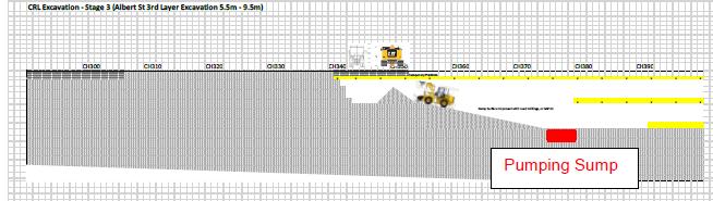
A movable pumping sump will be established for each excavation layer. The purpose of the sump is to provide some attenuation and averaging of flows as well as providing an easily maintainable space to allow sediment to drop out of suspension prior to the water being pumped to the water treatment plant (WTP) Refer Figure 5 below.
Figure 5 Schematic showing location of movable pumping sump
The sump will be moved within the trench as excavation progresses due to the confined space within the trench and co-located construction activities.
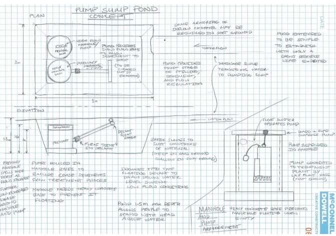
The pumping sump will consist of a hole excavated below the invert of the current lift and will contain (Figure 6):
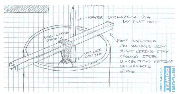
Concrete manhole risers to house pumps and set water levels. Base and high flow submersible pumps will be installed inside the manholes.
Connectus
Project #: 2665
Client: Auckland Transport
Erosion and Sediment Control Plan
Doc. No. CRL-PAT-ENV-CON-PLN-000897
Revision: 04, Date: 21 March 2016
A floating decant (similar to a TP90 design) included on the primary manhole to allow the pumping sump to drain down during dry conditions. This will facilitate sump clean out and restore storage capacity in the sump.
Figure 6 Schematic showing sump and pump arrangement
4.4.3.2 Trench Dewatering- Phase 2 Trench Excavation
Sediment-laden water will be pumped from the trench, through a water treatment plant), and then discharged to the stormwater network once it has reached the appropriate effluent quality standard
Project #: 2665
Client: Auckland Transport
Three pumps will be used to lift water from the base of the trench:
Erosion and Sediment Control Plan
Doc. No. CRL-PAT-ENV-CON-PLN-000897
Revision: 04, Date: 21 March 2016
1) Base flow pump - sized to lift the expected daily average flows out of the trench to the water treatment plant. This will be an electric submersible pump operated by a float switch. The pump will be sized to avoid frequent on / off cycling. (14L/s – refer below).
2) A standby duty pump – sized to lift the maximum treatable flow to the water treatment plant. This pump is expected to operate during rainfall events and will be sized to provide the maximum allowable flow to the WTP. This pump will also be operated by a float switch. (14L/s – refer below).
3) A high volume emergency pump – sized to deal with flows from the low probability rainfall events. This pump will discharge water directly to stormwater without treatment. Its purpose is to prevent health, safety or environmental incidents that could result if substantial flooding of the trench were to occur. This pump will be operated by a float switch with manual start and stop facilities. (This is likely to be in the order of a 50L/s pump).
Electric pumps are preferred over diesel or petrol powered pumps in line with the Project’s sustainability goals (reduced carbon footprint) and because automatic controls are easier to establish than for combustion engine driven pumps. Pumps will be connected to the WTP via lay flat hoses and cam-lock fittings which are easy to set up and reconfigure.
In order to predict the performance of the system, and size the pumps appropriately, modelling was undertaken using HEC-HMS – using the inputs detailed in Table 9
While the contributing catchment of the trench has been calculated at 3700m2 (refer section 2.2 of this ESCP) the modelling applied a safety factor (approximately 50%) to allow for additional flow from adjacent catchments entering the trench.
Table 9: Modelling input parameters
3/day
Rainwater catchments
Rainfall events tested
Dewatering system capacity
Pump capacity
5780m2
Time-series (2011, 2008, 2004) – taken from the Albert Park rain gauge.
1 in 20 year SCS design storm
Two units of 50m3/hr each – operated under normal conditions at half capacity (based on the siltbuster HB50).
Primary pump – 14L/s (50m3/hr) to match capacity of the siltbuster HB50
Secondary pump – 14L/s (50m3/hr) to manage peaks
Average groundwater inflow as provided
Surface area of the trench with added safety factor.
Based on manufacturers specifications
Trench dimensions
18m deep, 20m wide, 3.8% base slope.
Based on drawings provided. This provides the basis for storage which was modelled
Project #: 2665
Client: Auckland Transport
Pump settings (depth in m above trench invert)
Start 0.6m, stop 0.2m
The modelling results are summarised in Table 10.
Table 10: HEC-HMS Trench and pump modelling results
Erosion and Sediment Control Plan
Doc. No. CRL-PAT-ENV-CON-PLN-000897
Revision: 04, Date: 21 March 2016
Set based on acceptable levels of inundation within the trench
*Note: 0.8m depth equates to a flooded length of 20m; and a 1m depth equates to a length of 26m.
a) Time series: The results indicate that using a 14L/s pump, the maximum trench elevation achieved ranged between 0.9 and 1.1m. The worst case year was 2011, which resulted in 12 hours of the total year being above 0.8m depth, and only 2 hours above 1m. This length of time is considered acceptable, and depending on whether the working face is at the down-slope end of the trench area or not, the water level can be allowed to increase without compromising the work progress. These results confirm that all the water can be removed at a rate that can be managed by the WTP capacity.
b) 1 in 20 year, 24 hour design storm: In an extreme event such as this, works will be halted, and the water level within the trench will be allowed to increase temporarily to a higher level. Modelling using a 14L/s pump (half capacity of 2 x siltbusters) – would result in a peak water level of 1.0m within the trench base, and the total volume of approximately 900m3 would take around 15 hours to pump out through the WTP (refer Appendix B of this ESCP). Using a 28L/s pump (max capacity of Siltbusters) would reduce the peak water level to 0.9m, and reduce the pumping time during the peak to around 5 hours (refer Appendix B of this ESCP). These results confirm that all the water can be removed at a rate that can be managed by the WTP capacity.
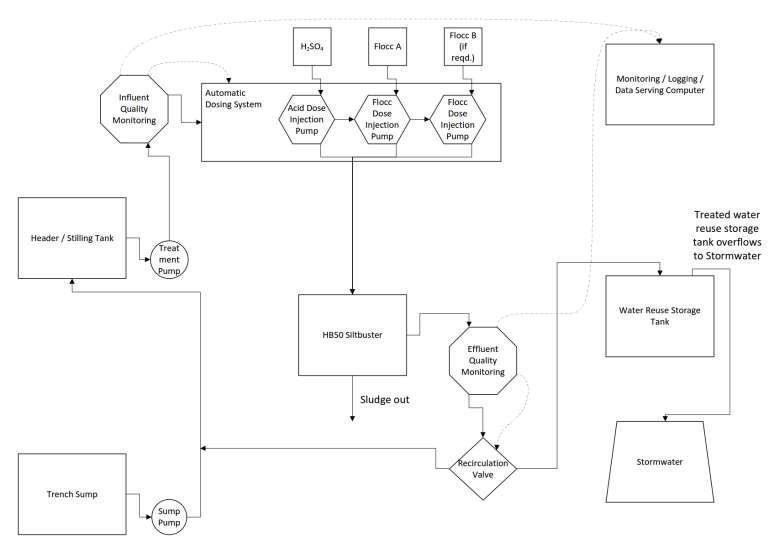
4.4.3.3 Water Treatment Plant
The WTP will utilise a treatment train approach consisting of the following components (Figure 7):
1. Mixing header Tank
2. Influent Quality Monitoring devices
3. Dosing system
4. Sediment settling and dewatering Tanks (eg Siltbuster Clarifiers)
5. Effluent Quality Monitoring device
6. Treated water storage/reuse
7. Discharge to stormwater network
Project #: 2665
Client: Auckland Transport
Erosion and Sediment Control Plan
Doc. No. CRL-PAT-ENV-CON-PLN-000897
Revision: 04, Date: 21 March 2016
Project #: 2665
Client: Auckland Transport
1) Mixing Header Tank
Erosion and Sediment Control Plan
Doc. No. CRL-PAT-ENV-CON-PLN-000897
Revision: 04, Date: 21 March 2016
The first stage in the treatment train consists of a mixing/header tank. The mixing facility serves to homogenise the influent water. Rapid changes of influent water quality are evened out so that gradual changes in water quality will be fed to the rest of the treatment train. This approach reduces the frequency and magnitude of dosing adjustments. In addition, during very low flows, the tank may be used to store water for batch processing.
2) Influent Quality Monitoring
After the mixing tank, inline pH and Total Suspended Solids (TSS) meters will gather continuous influent water quality data which will be fed to the pH and flocculent dosing system
3) Dosing System
Three types of chemicals will be employed to assist the lamella clarifiers in treating water to achieve the consented water quality standard:
Coagulants
Flocculants
pH neutraliser/increase
An electronic dosing device will be used. An example of this is provided within the Chemical Treatment Management Plan (Appendix D of this ESCP)
4) Sediment Settling and Dewatering
The treatment system will have a sediment settling and dewatering stage. The pump capacity calculations have been based on using two lamella clarifier tanks known as ‘Siltbusters’.
Siltbuster™ HB50 tanks have been used successfully in New Zealand and overseas, and are understood to be accepted by Auckland Council (personal communication with Malcolm Todd, Babington & Associates Ltd). Figure 8 shows a schematic of a Lamella Plate Clarifier.
The Siltbuster HB50 unit is a highly effective mobile lamella clarifier and has been specifically designed to provide water clarification for a range of applications. Process water, groundwater or site runoff can be treated either for re-use or discharge off site either to watercourse or stormwater system.
Refer to Appendix C of this ESCP for details of the clarifier unit.
Each unit has a maximum recommended hydraulic capacity of 50m3/hr (14litres/sec).
Estimates of average long term groundwater flows are in the order of 16m3/day with higher initial short term inflows of 30-60 m3/day depending on the zone and the construction methodology. A series of rainfall events (time series and design storm) have also been modelled to predict the performance of the Siltbuster unit (refer section 4.4.3.2 of this ESCP). These results show the two units proposed will have sufficient capacity to manage expected inflows. For events greater than this, water will fill up the lower reaches of the trench until such time that the WTP can process the extra volume.
In terms of the treatment performance the units are material specific and nominally designed to achieve 90% removal of the +15 micron diameter particles (medium sized silt) at a flow rate of 45m3/hr, +10micron at 20m3/hr and some +6 micron at 5m3/hr. Under normal operating conditions the unit will also remove a significant proportion of the material in the 2 to 15µm (fine to medium sized silt) range. These are based on average particle densities.
Project #: 2665
Client: Auckland Transport
Revision: 04, Date: 21 March 2016
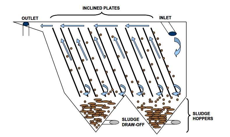
Manufacturer’s information suggests that the unit alone will not typically remove very fine particles such as very fine silt or clay without chemical additives, hence the need for the dosing system to achieve the required discharge quality. Effluent discharge quality and monitoring is discussed below. A CTMP has been prepared which allows for the use of flocculants to enhance settling if required. The CTMP is provided in Appendix D of this ESCP. An automatic dosing system using HaloklearTM biodegradable flocculant is proposed. This allows for rapid deployment of flocculant as required, based on bench testing and managed through influent readings taken on site.
5)
An effluent quality monitoring system will be installed after the Lamella Clarifiers to determine if the treated water meets the required discharge standards.
The electronic dosing device will monitor TSS and pH. If the monitoring system identifies water that does not meet the required standard, a recirculation valve will operate to send the water back to the start of the treatment process for re-treatment. In addition weekly samples will be taken as follows:
Total Suspended Solids mg/L
Copper (total) mg/L
Zinc (total) mg/L
Lead (total) mg/L
Total Petroleum Hydrocarbons mg/L
The plant operator will be informed about the water treatment plant performance to allow fine tuning.
To reduce the Project’s reliance on potable water from mains supply, treated water will be stored in a 25,000L storage tank. When the tank is full water will be diverted for discharge to the local stormwater system. Stored water will be used for dust suppression, and any other use for which the water is deemed suitable.
7) Discharge
Project #: 2665
Client: Auckland Transport
Erosion and Sediment Control Plan
Doc. No. CRL-PAT-ENV-CON-PLN-000897
Revision: 04, Date: 21 March 2016
Excess treated water above the quantity that can be practically stored for reuse will be discharged to AC’s reticulated stormwater network. A practical connection point will be selected based on downstream pipe diameter to ensure there is sufficient capacity in the downstream stormwater network to avoid backflows and flooding. . The connection will be made by replacing the standard lid with a modified lid incorporating a camlock fitting or similar to create a robust secure connection. However as work on the project progresses there may be opportunities or operational necessities that force the relocation of the discharge point.
Rail tunnel construction and trench backfilling will occur progressively from the south end to the north end over a period of approximately 12 months. The trench backfill will be placed on top of the tunnel structure after tunnel construction has been completed for a sufficient length (approximately 50m), including the installation of the waterproofing membrane, and will continue to follow the tunnel construction as it progresses.
During the backfilling of the trench, fill will be transported to the site and loaded onto the construction platform by and pushed into the trench by a small frontend loader. The rate of backfilling will be determined by the progression of the tunnel construction. Depending on delivery times of the fill required for the backfilling operation, a storage area will be set up at the southern construction support area (CSA 6). The stock pile area will be approximately 20m by 5m allowing average storage of 150m3
The platform area where trucks exit onto the public traffic lane will be kept clean by regular sweeping of any loose sediment/spoil back into the trench and waterblasting where required. All dirty water will be directed into the trench.
Dirty water within the trench will continue to be conveyed and treated by the WTP located at the north end of the tunnel until such time the plant needs to be removed from the trench. As progress with the backfilling is made and the trench stabilised, the water treatment plant equipment will be downsized to settling tanks with flocculants (Level 3 Control).
Drawing SKE – 0356 (Appendix A of this ESCP) shows the layout of CSA 6 which includes a fill stockpile as well as storage of other material and offices. Where material is not being delivered directly onto the construction deck for immediate use in backfilling, it can be delivered and stored temporarily in CSA 6. Trucks can enter the CSA from the northbound traffic land or southbound from the construction deck. It is likely that trucks delivering fill will enter the CSA from the south h, tipping the fill into the stockpile area, reversing and continuing north in the public traffic lane. However the majority of fill will be delivered directly to the backfilling zone.
Regular road sweeping will be carried out along the adjacent streets where trucks leave the site to ensure that no deposition of earth, mud, dirt or other debris remains on any road or footpath. Where these areas require washing with water, dirty water will be directed to the trench where it can be treated by the WTP.
Permanent measures to ensure sediment laden water does not enter the stormwater system during rainfall events include:
Erecting an impervious barrier around the stockpile
Installing a bund to capture and divert sediment laden water into the trench where it can be treated by the WTP. The sump and WTP will continue to operate as described in Section 4.4 of this ESCP during trench back-filling to collect and treat dirty water within the trench.
Erosion and Sediment Control Plan
Project #: 2665 Doc. No. CRL-PAT-ENV-CON-PLN-000897
Client: Auckland Transport
Revision: 04, Date: 21 March 2016
During a rainfall event, the stockpile will be covered. In the event of unforeseen heavy rainfall, these control measures will be checked and upgraded or modified where necessary e g extra bunding may be required.
The industrial and trade activities, including temporary storage activities within the construction support areas, are addressed through the Project Industrial and Trade Activities Environmental Management Plan (ITA EMP) provided in Appendix K of the Project CEMP.)The purpose of the ITA EMP is to manage the Industrial Trade Activity that will be undertaken in CSA 4 and CSA 6. It provides a framework for the effective management of stormwater discharges from the Northern Compound (previously called CSA 4 and CSA5) and the Southern Compound (CSA 6).
Management of the fill stock pile at CSA 6 is discussed in Section 4.5.1 of this ESCP
Within CSA 4 there will be a stockpile containing aggregate for jet grouting (sand) In the event of rain, this will be covered and sediment socks placed around it. The downstream catchpit will be protected by a catchpit filter.
Prior to construction (bulk earthworks) commencing, a certificate signed by a senior qualified person shall be submitted to Auckland Council (AC - Team Leader Central Monitoring) to certify that the erosion and sediment controls relevant to the proceeding stage of works have been constructed in accordance with the certified ESCP(s).
Certification details of diversion bunds and sumps will be supplied immediately upon completion of construction. Information supplied (if applicable) will include:
a) contributing catchment area;
b) shape of structure (dimensions of structure);
c) position of inlets/outlets;
d) stabilisation of the structure; and
e) Where diversion bunds are used- certification for these shall be supplied immediately upon completion. Information supplied, if applicable, shall include:
contributing catchment area;
shape of structure (dimensions of structure); and
position of inlets/outlets;
As part of the erosion and sediment control measures, on-going site monitoring by the contractor and wider project team will be undertaken. This will ensure that all of the control measures detailed in this ESCP have been properly implemented and are functioning effectively.
Monitoring will occur for the full duration of the works. Any control measures requiring maintenance or adaptation to allow construction tasks to occur shall be identified and implemented by the Environment and Sustainability Manager to ensure continual compliance. Visual assessments of discharges within the receiving environment will be conducted, especially following significant rainfall events. Weather forecast data will be utilised during the works, with works being programmed in accordance with weather predictions.
Of particular importance will be monitoring the performance of the settlement tanks (eg Siltbuster Units). The performance of the unit and the degree of additional flocculation required is discussed further in Appendix C of this ESCP.
As per the Project CEMP (Section 4.1.2), the Cut and Cover Construction Manager and the Environment and Sustainability Manager will be responsible for implementation of this ESCP, including the operation and maintenance of all specified erosion and sediment control measures (Table 11)
Table 11 Roles responsible for implementation of the ESCP
Role
Cut and Cover Construction Manager
Environment and Sustainability Manager
Role Responsibilities
Reviewing and reporting on environmental performance. Inspection of works to assess compliance with the ESCP and sub-plans – including operation and maintenance of the Chemical Treatment System, including daily monitoring.
Inspections, auditing and checking of environmental management practices and procedures.
On-site compliance with consent conditions and other requirements and tracking compliance information.
Report to AT changes to construction techniques or natural environmental changes which require alterations to existing consents or new resource consents.
Prepare, review and update of CEMP and relevant sub-plans (including ESCP and CTMP).
Facilitate and oversee environmental monitoring -– including daily Chemical Treatment System monitoring.
Update and maintain the environmental portion of the Project Risk Register.
Training of all staff including subcontractors.
Project #: 2665
Client: Auckland Transport
Erosion and Sediment Control Plan
Doc. No. CRL-PAT-ENV-CON-PLN-000897
Revision: 04, Date: 21 March 2016
Monitoring will be undertaken based on the elements and frequencies in Table 12 Inspection sheets will be used to record notes relating to each inspection, and associated corrective actions. The sheet will be signed by the Environment and Sustainability Manager after each inspection.
Table 12 Monitoring elements
Element
Clean water diversions (bunds), barriers (sediment) and overland flow paths
Stockpiles (spoil, fill, aggregate)
Weekly and before forecast rain events
Daily
Dirty water Filters
Settlement tank effluent
Drains and sumps / pumps
Settlement units and related dosing system and discharge points
Daily
Daily
Daily
Daily
Hazard waste storage areas Daily
General site inspection Daily
Are diversions and barriers in the correct places and sealed appropriately? Are overland flow paths kept clear as far as practical?
Are stockpiles contained within designated areas? Are covers in place? gutter drains in place where required? Is there any leaching of sediment-laden water? Does any dampening-down need to occur?
Is there any leaching of sediment-laden water?
Is the effluent clarity 10cm or greater measured with a black disk, pH between 5 and 9, and no visible TPH?
Are drains and sumps functioning correctly?
Are the inlet and outlet to the Settlement units cleared and running correctly? Has the unit been de-sludged as per the suppliers instructions? Is the effluent quality monitored as per this document and the CTMP?
Are storage areas away from any flow paths? Are containers correctly sealed and stored?
General cleanliness of site. Do truck loading and unloading areas require cleaning with water? If so check dirty water can be collected and treated.
In addition to formal monitoring and maintenance activities described above, all personnel will receive training of a type and level of detail that is appropriate for the environmental aspects of their routine and emergency work assignments as outlined in Section 4.1of the Project CEMP.
Site personnel involved in earthworks are required to be competent in erosion and sediment control processes as well as identifying contaminated soils, and will therefore complete a training program specifically targeted on this area.
Tool Box Talks are conducted for site personnel to deliver specific training in an aspect of work or controls, such as correct erection of a bund or filter sock and how to identify if these are working properly.
Connectus
Project #: 2665
Client: Auckland Transport
Erosion and Sediment Control Plan
Doc. No. CRL-PAT-ENV-CON-PLN-000897
Revision: 04, Date: 21 March 2016
A Project Communication and Consultation Plan (Appendix O of the Project CEMP) has been developed by Connectus. It details the strategy, tools and process to manage communication and engagement between Connectus, its stakeholders and the community throughout the construction and monitoring periods for the Project, including how complaints and queries will be responded to. Any sediment runoff related complaints will be recorded on the Environmental Incident Report Form (CONCRL-EC2-ENV-FRM-000599) and entered into the Complaints Register
Project #: 2665
Client: Auckland Transport
Revision: 04, Date: 21 March 2016
Construction work will be avoided during heavy rainfall events. Before forecast heavy rainfall events, additional cleanwater diversion and catchpit protection devises may be installed around utilities and piling work.
During the Trench excavation and in the event of an unforeseen heavy rainfall, runoff will collect within the excavation. Works within the excavation will stop until all accumulated water is pumped to the relevant treatment device for treatment. Due to the significant depth and size of the excavation, overflows of collected rainwater are not a concern.
Project #: 2665 Doc. No. CRL-PAT-ENV-CON-PLN-000897
Client: Auckland Transport
Revision: 04, Date: 21 March 2016


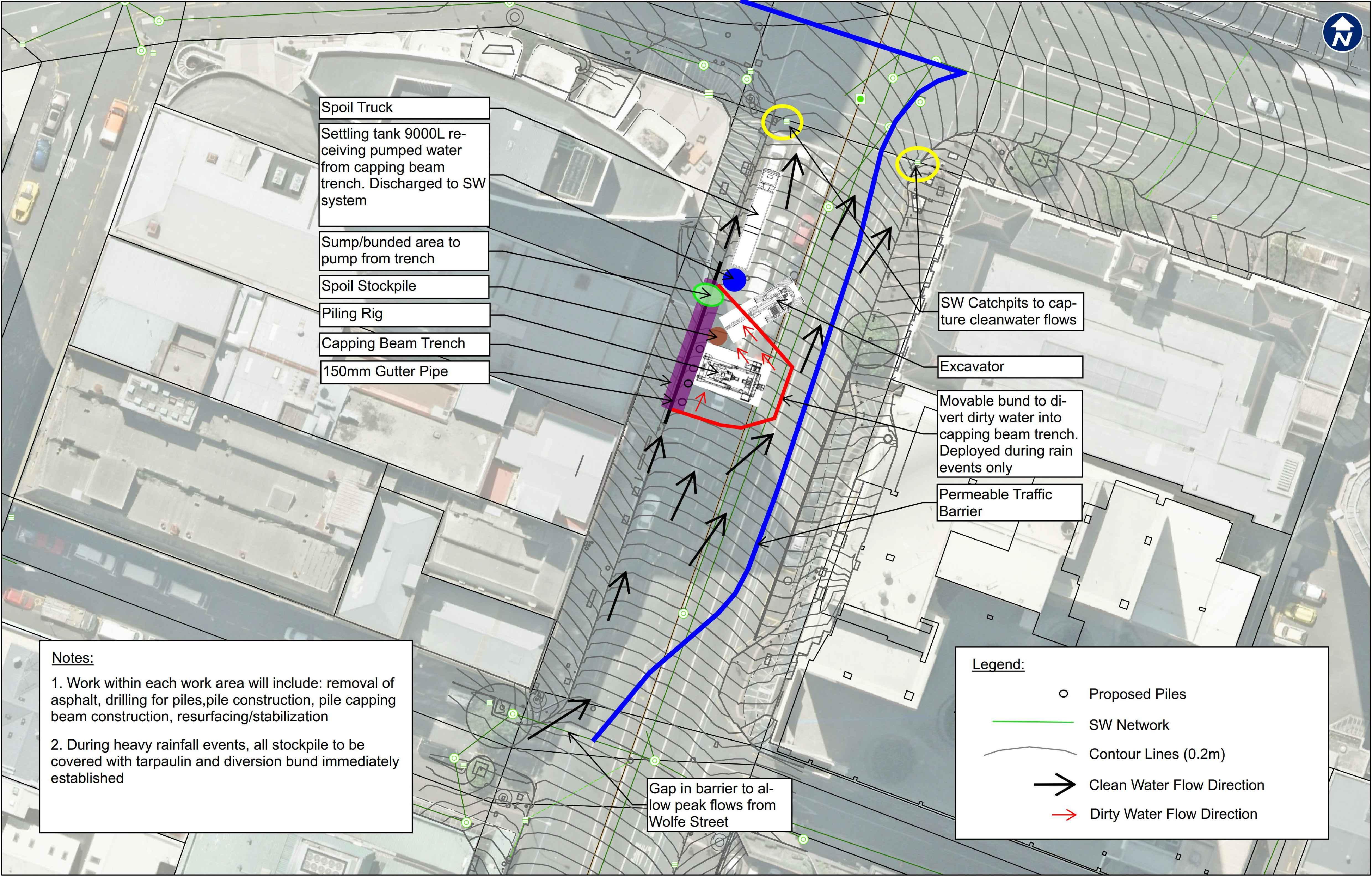

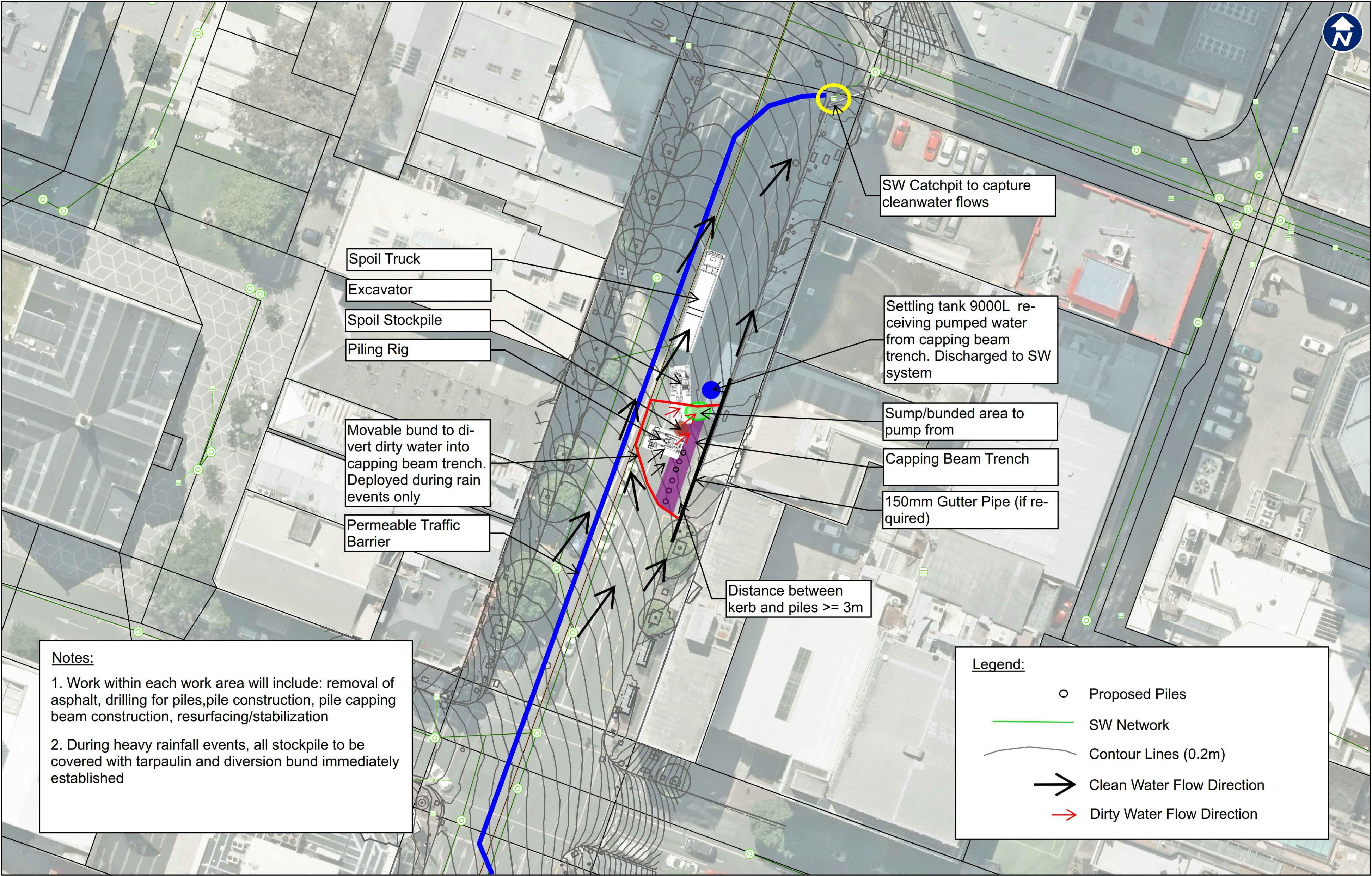
Connectus Erosion and Sediment Control Plan
Project #: 2665 Doc. No. CRL-PAT-ENV-CON-PLN-000897
Client: Auckland Transport
Revision: 04, Date: 21 March 2016
Relationship
2.6
3 79.00434786 78.94736842 118.4210526 2368.421053
3.2 84.27130438 84.21052632 134.7368421 2694.736842
3.4 89.53826091 89.47368421 152.1052632 3042.105263
3.6 94.80521743
4.2 110.606087 110.5263158
4.8
5.4
5.6
5.8
6.4
6.8
7.2
7.4
7.6
8.2
Modelling Summary Table
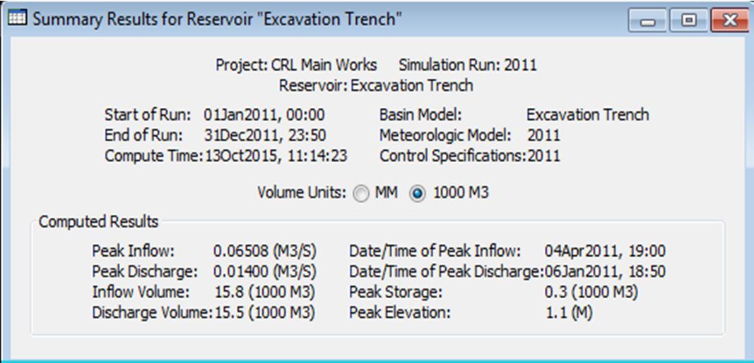
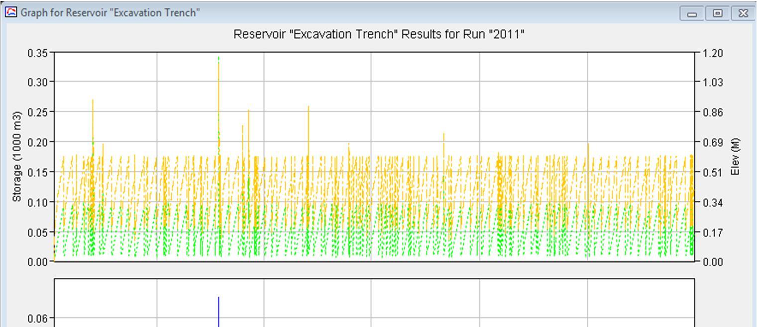
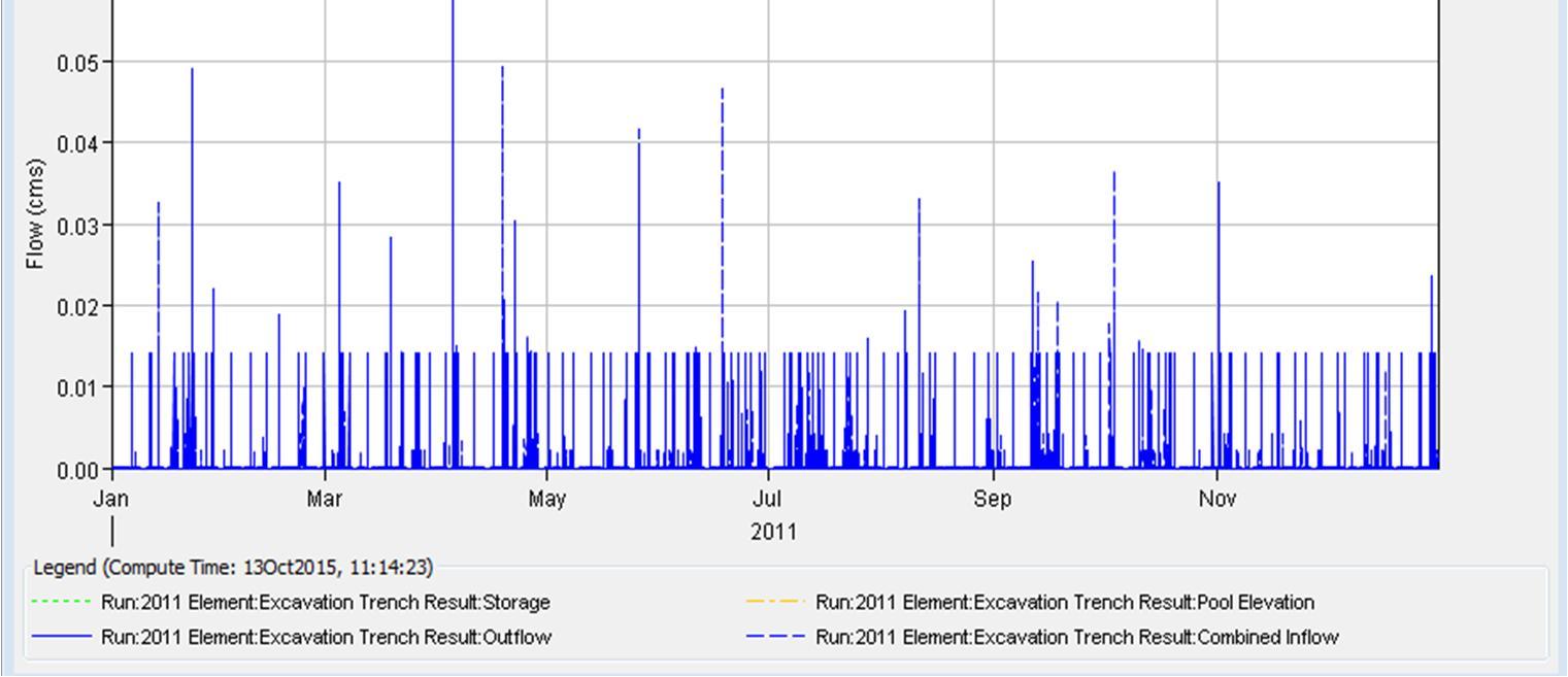
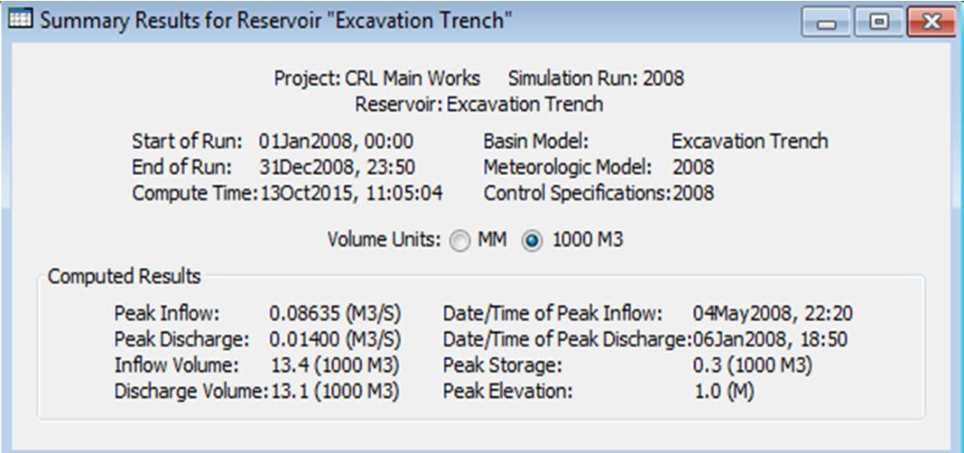
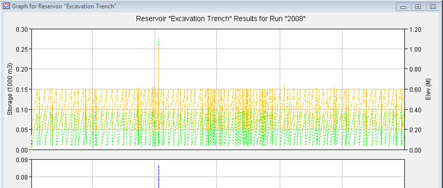
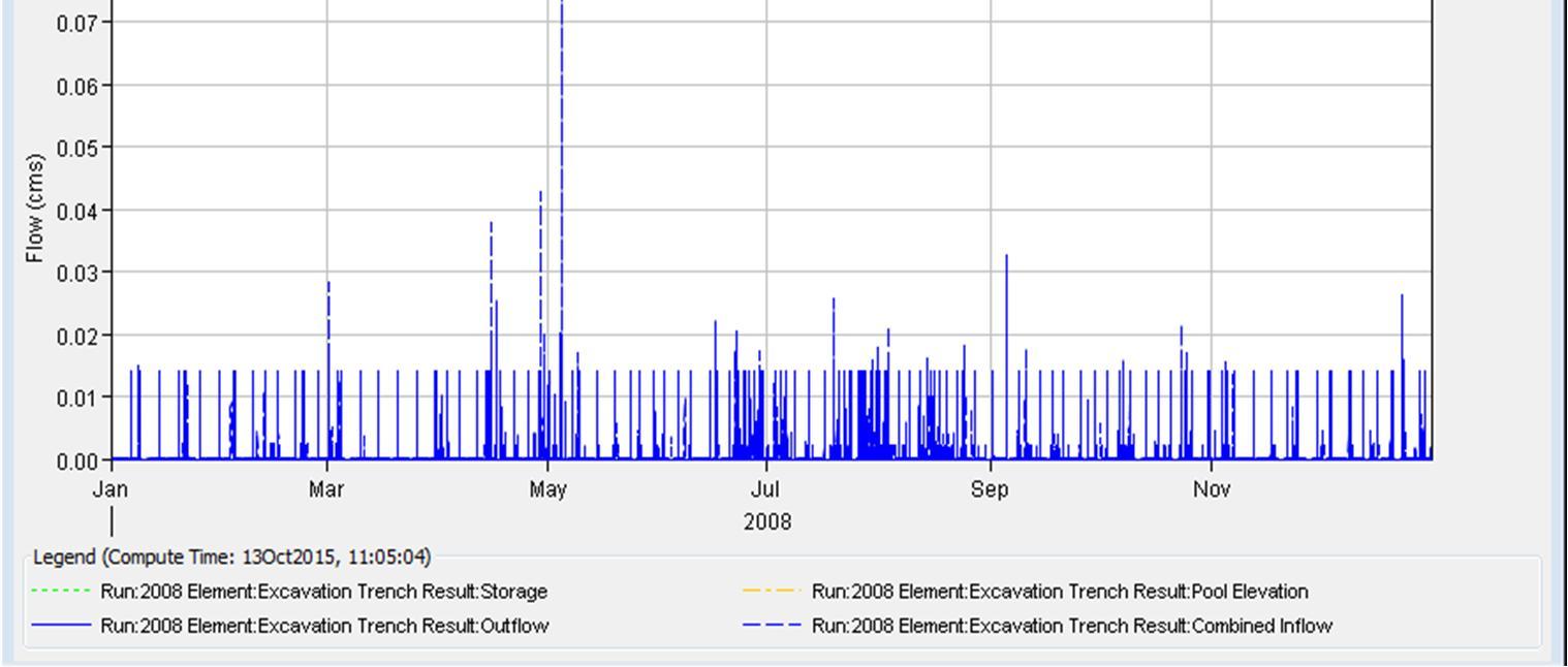
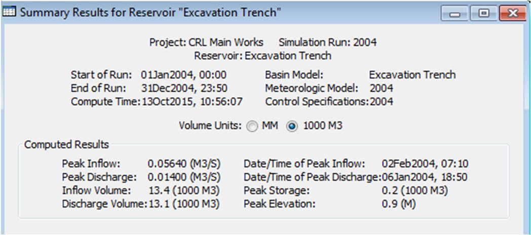
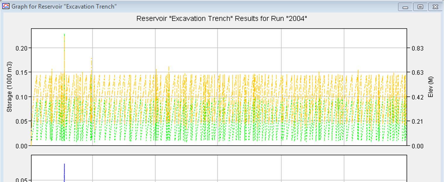
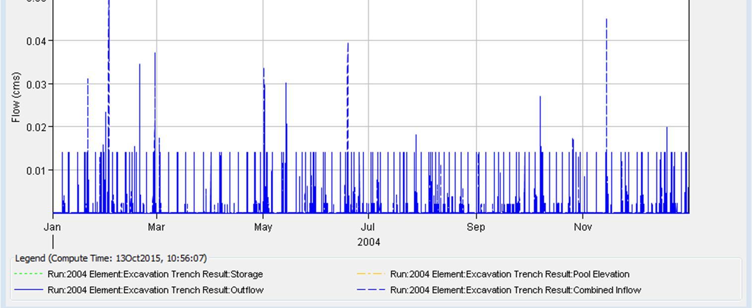
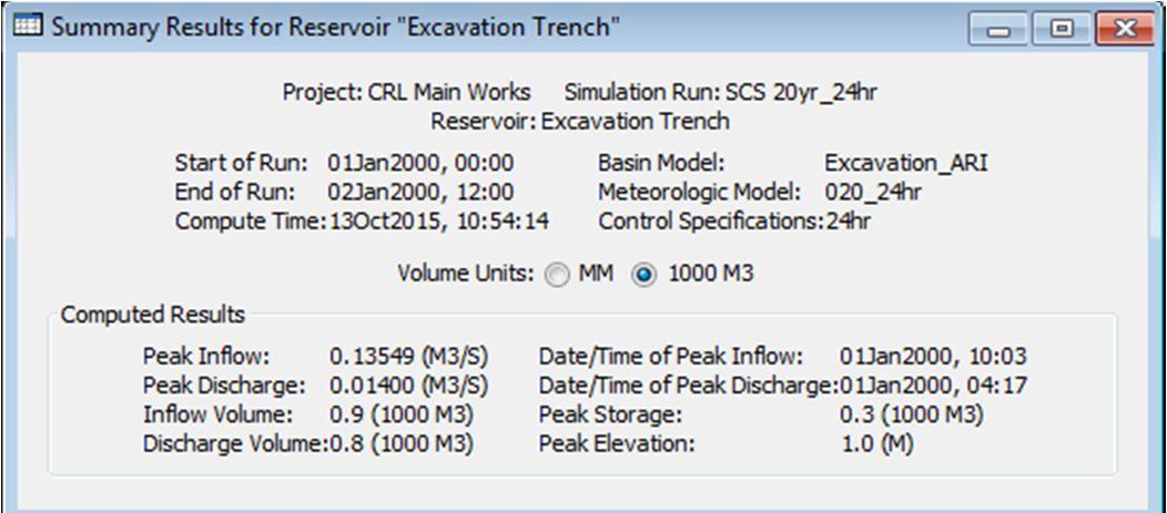
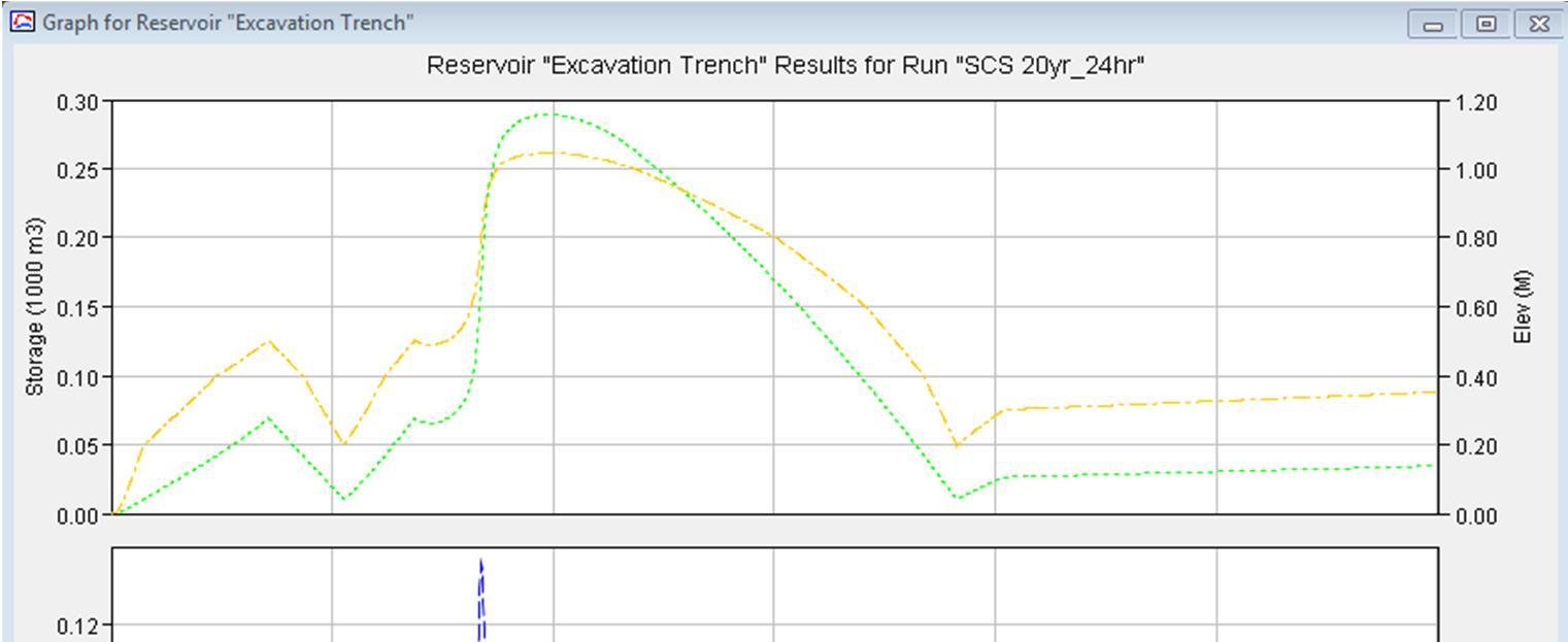
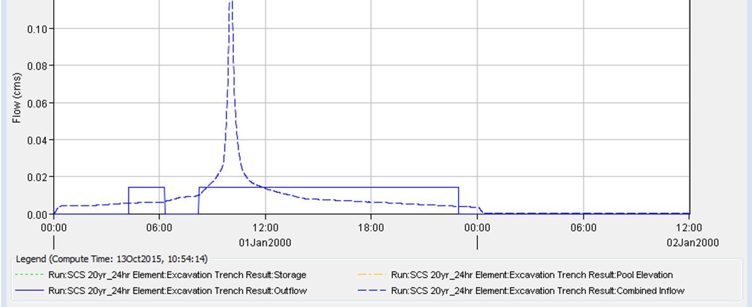
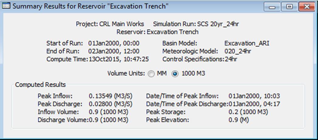
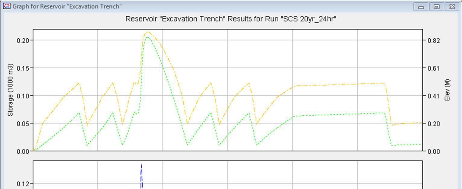
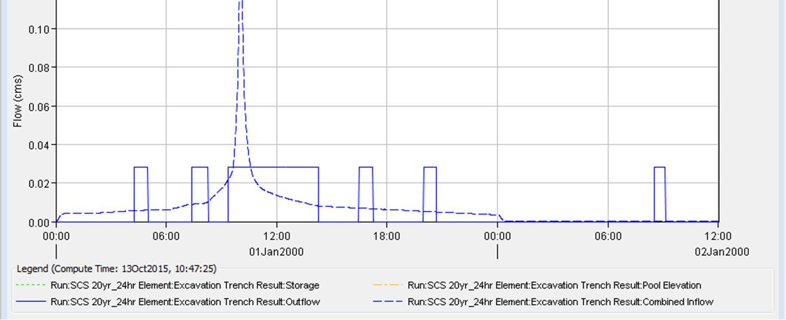
Connectus Erosion and Sediment Control Plan
Project #: 2665 Doc. No. CRL-PAT-ENV-CON-PLN-000897
Client: Auckland Transport
Revision: 04, Date: 21 March 2016


3.0
4.0
5.0
The Siltbuster HB50 units are highly effective mobile lamella clarifiers and have been specifically designed to provide water clarification for a range of applications. Process water, groundwater or site runoff can be treated either for re-use or discharge off site either to watercourse or sewer. The units are ideal for removing free phase oil from water being discharged to sewer or river.
All our units are “Registered Designs”, Patented or have Patents Pending.
1.1 Principal Components & Features - Siltbuster HB50
(fig 1.1)
All tank components are fabricated from Mild Steel
The unit will be painted to the following spec.
External surfaces – abrasive blast to Class 2.5, painted in a Jotacoat 605 two pack epoxy to 250µm with a Top Coat hardtop ultra pack "Polyurethane" to 50µm, colour G11, bottle green.
Siltbuster HB50 Operation and Maintenance Manual
Internal Surfaces - abrasive blast to Class 2.5, painted 2 pack epoxy coating reinforced with glass flakes to 500µm, colour N52 Mid Grey.
Water Inlet – 4” BSP threaded connection.
Water Outlet – 6” Socket c/w 6” Female Bauer fitting.
Water Drain- down Valve – 2” Threaded connection.
Sludge Discharge Valves – 4” flanges for connection of sludge valves.
The Siltbuster HB50 unit incorporates four lifting eyes, one located at each of the upper corners of the unit for lifting with chains, straps etc. Fork Lift channels are also provided at the base of the unit to enable lifting by a fork lift/JCB with fork attachment. (ref fig 2.1 below)
Transport Tie Down Points
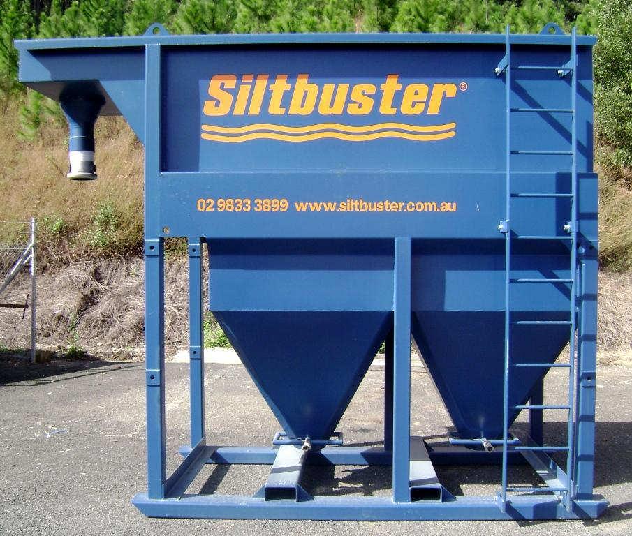
(fig 2.1)
WARNING:
Forklift lifting Channels
The unit should NOT be lifted or moved by attaching lifting equipment to any other part of the unit as this may result in damage to the unit or cause personal injury.
Lifting points are structurally designed and certified to lift the unit when empty.
NOTE:
The unit should only be lifted WHEN EMPTIED OF WATER AND SOLIDS.
The sludge valves should be in the “OPEN POSITION” whilst been transported.
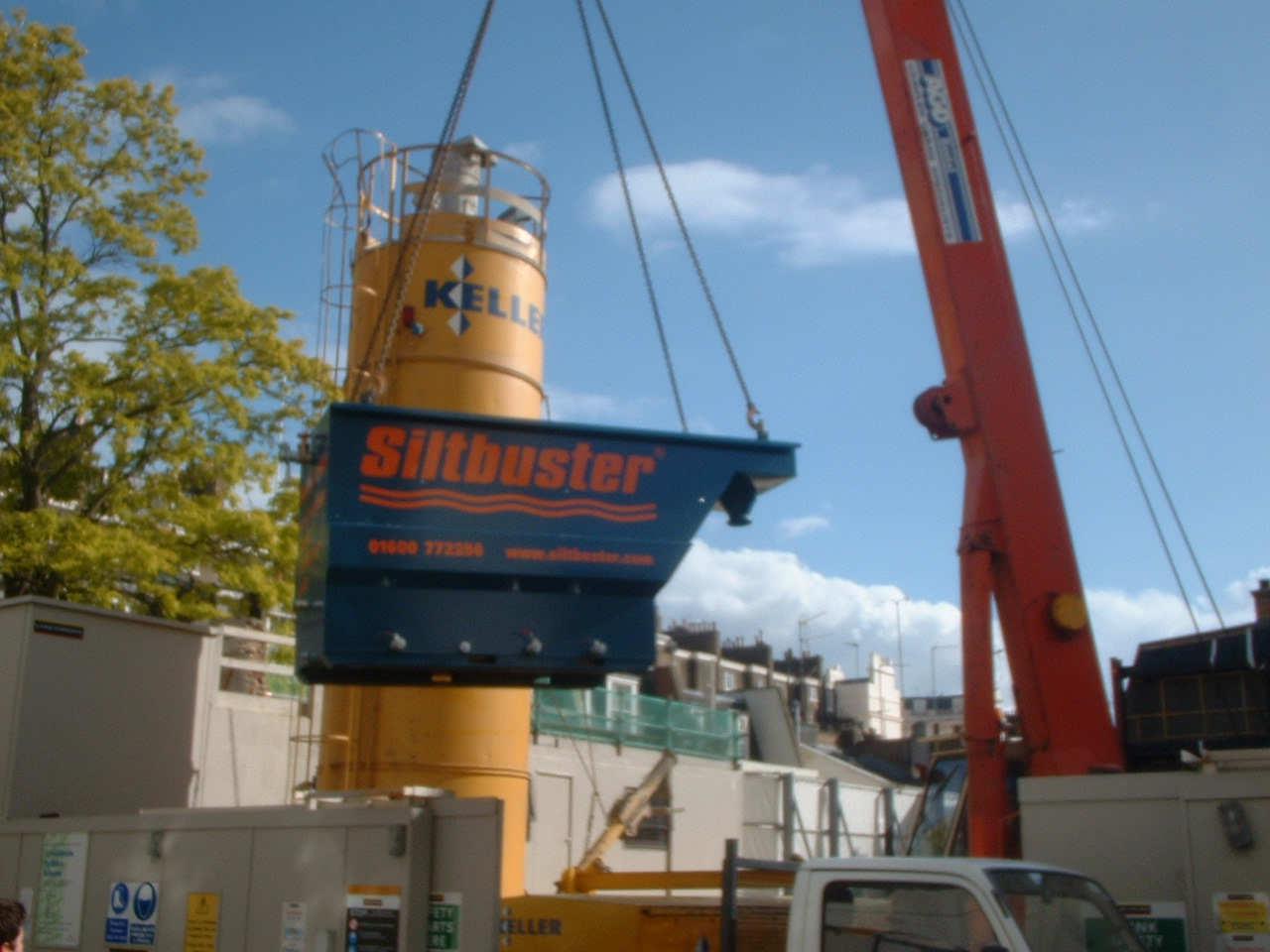
WARNING:
When shifting units with a forklift select a forklift with suitable capacity to lift the unit (suitable Working Load Limit to suit the load at the centre) and capable of traversing the site safely. (ref fig 2.3)
Consider height of the load when travelling and identify hazards and risks on site and along your travel route.
(fig 2.3)
Size – overall dimensions:
Width - 1700mm
Length- 3700mm (3900mm with inlet fittings attached)
Height - 3100 overall (with lifting eyes)
Weight - 2500kg (empty but with all plates and fittings). Weight full (wet) 9,000kg approx.
Centre of Gravity – The units centre of gravity is the middle point between the four lifting points.
Manufacturing Date: November 2009
Model Number: HB50
Supplier: EnviroWaste Technical Services 09 636 0350
Tie down points are provided on the units to ensure load is secured during transport. Units must be secured at all four the points prior to transporting.
The Siltbuster HB50 series is 3.1 metres high and may require an oversized permit to carry on a normal flat top semi trailer.
The Siltbuster HB50 should be located in a position where:
• The ground is firm enough to support the flooded weight of the unit (approx. 10 tonnes).
• The ground is reasonably level. The top edge of the unit should be placed level to within 10mm.
• Due to the weight of the unit permanent anchoring is not required. However if this option is required then either holes can be drilled into the skids or straps constructed and placed over the skids in each corner and bolted to the ground.
• Sufficient clearance overhead is required to allow for the periodic removal of individual lamella plates.
• Safe access to the unit is available for routine inspection and maintenance.
• There is no likelihood of the site eroding during heavy rain or runoff.
• Adequate security can be provided from unauthorised access.
• Removal of sludge can be carried out safely and without risk of polluting site.
Note:
1. Ladders provided on Siltbuster units are for the purpose of climbing to carry out visual inspection only while maintaining a three point grip and are not intended for carrying out tasks.
2. The purchaser/hirer is responsible for assessing the site and determining prevailing hazards or risks. Advice offered in this brochure only highlights some common hazards and risks and is not intended as a complete checklist.
3. The purchaser/hirer is responsible for identifying hazardous or toxic products contained within the materials processed through the units and must develop safety control measures for staff and others who may be affected.
4. If placing units in elevated position hirer/purchaser should consider distance from ground surface to top of unit in regards to relative state regulations on working at heights.
The Siltbuster unit itself requires no power, has no filters or moving parts. As a result, apart from emptying as required, the unit is virtually maintenance free.
The Siltbuster HB50 has a maximum recommended hydraulic capacity of 50m3/hr (14litres/sec).
The performance of the unit is material specific and the Siltbuster 50 Series is nominally designed to achieve 90% removal of the +15 micron diameter particles (medium sized silt) at a flow rate of 45m3/hr, +10micron at 20m3/hr and some +6 micron at 5m3/hr. Under normal operating conditions the unit will also remove a significant proportion of the material in the 2 to 15µm (fine to medium sized silt) range. These are based on average particle densities.
The Siltbuster will not typically remove very fine particles such as very fine silt or clay without chemical additives. The unit will also not remove colour from water.
The volume of water which can be processed by the unit is dependant upon the nature of the liquid/solid mix to be processed. The graph below (fig 7.1) provides only a general performance guide. The hydraulic capacity is 50m3/hour.
(fig 7.1)
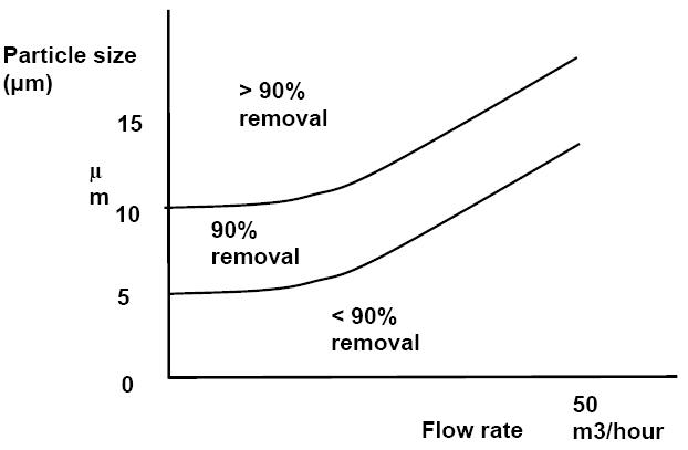
The frequency of emptying the Siltbuster HB50 unit is dependent on the solids loading and the nature of the solids. Larger grain sizes (sands to gravels) do not generally flow as easily as finer sizes (silts) and tend to need more frequent cleaning to prevent hanging up in the hoppers.
Typical emptying frequencies vary from daily to fortnightly and we suggest you empty “little and often” until you know the material you are dealing with and how long you can leave the sludge in the unit whilst ensuring it is still fluid and flowable.
If solids have become solidified (“set”) then the small 1” ball valves (“sparge”) allow water or air to be injected back into the hopper under pressure to re-agitate (fluidised) the solids. See fig 7.1 below.
(fig 7.1)
1” Sparge ball valves c/w Minsup fittings
Ref Maintenance Item Typical Frequency
1 General check over of unit Weekly
2 Emptying - removal of sludge As required
3 Draining of tank and washing down of plates As required
Notes:
1. The visual inspection should include inspection of the water surface for floating material (leaves etc).
2. Emptying: see previous instructions.(Section 8.0)
3. Some materials (especially charged particles) can adhere to the PVC plates and these will need periodic cleaning. The unit should be allowed to settle overnight, drained and then the PVC sheets pressure washed in-place.
All frequencies given depend on the usage of the equipment and are given as typical guides.
The unit’s settlement performance can be enhanced by:
• Linking multiple units in parallel;
• Chemical conditioning of the water to be treated by adding flocculants and/or coagulants to the feed supply. Should you wish to increase the performance of the unit in this way, please contact EnviroWaste Technical Services on 09 636 0350.
The Siltbuster HB50 itself requires no power, has no filters or moving parts and apart from emptying, the unit is virtually maintenance free.
As the nature of dirty water to be treated varies in terms of quantity and solids content, the table below lists some problems that could arise along with the actions required to solve the problems.
Water is overflowing from the inlet chamber or part way along main tank
Typical Causes:
1. Too much flow through unit (unit overloaded)
2. Sludge in contact with plates
Water discharge is dirty
Typical Causes:
1. Too much flow through unit (unit overloaded)
2. Water contains very fine silt and clay particles
1. Reduce flow through the unit
2. Unit needs emptying of sludge
1. Reduce flow through the unit
2. Add multiple units in parallel
3. Chemical conditioning of inflow required.
In any other cases contact EnviroWaste Technical Services 09 636 0350
12.0 GA Drawing
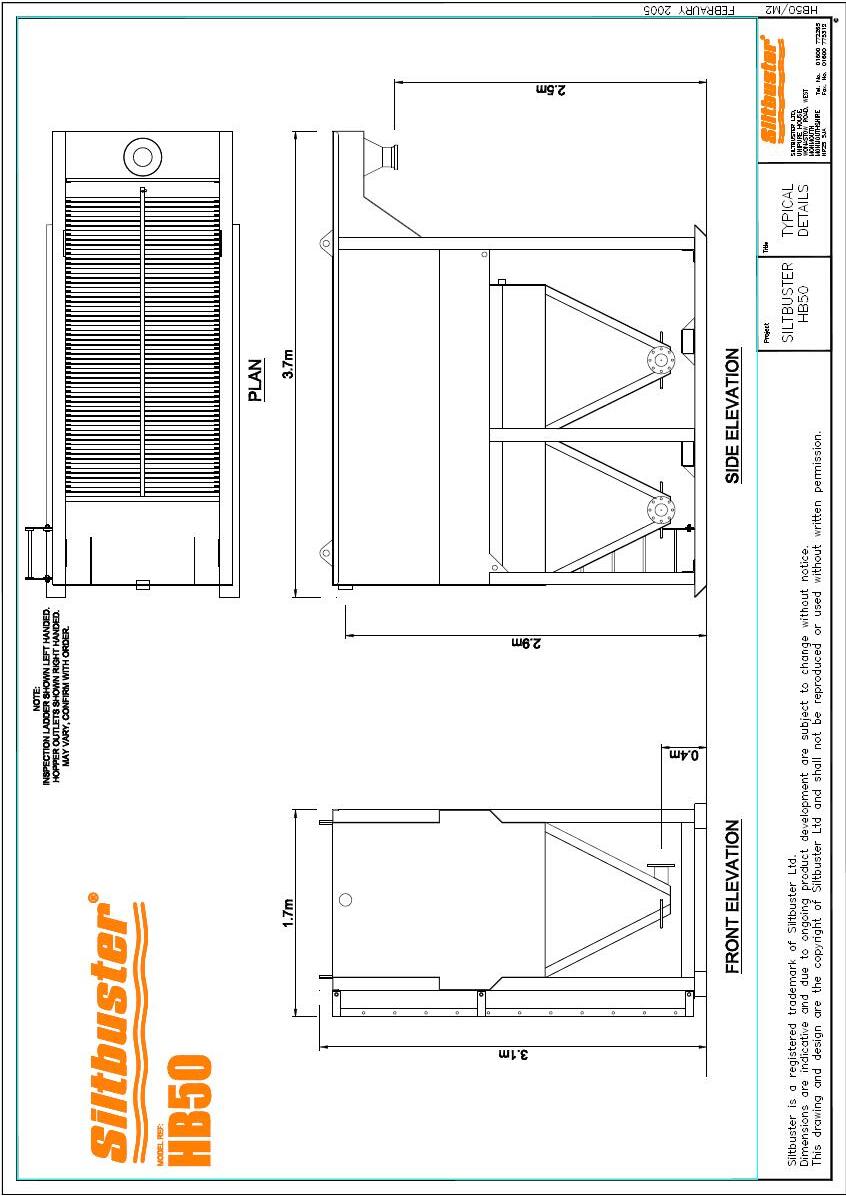
Connectus Erosion and Sediment Control Plan
Project #: 2665 Doc. No. CRL-PAT-ENV-CON-PLN-000897
Client: Auckland Transport
Revision: 04, Date: 21 March 2016
This page intentionally left blank.
Connectus
Project #: 2665
Client: Auckland Transport
Chemical Treatment Management Plan
Doc. No. CRL-PAT-ENV-CON-PLN-001033
Revision: 04, Date: 21 March 2016
Organisation: Connectus
Document Title: Chemical Treatment Management Plan
Fulcrum Document Number: CRL-PAT-ENV-CON-PLN-001033
Document based on MMS No: n/a
Client: Auckland Transport
Project: CRL Enabling Works: Contract Two
Location: Auckland CBD
Project No: 2665
1 16/10/2015 1st Draft for Connectus Review
01 21/10/2015 2nd Draft Sent to AT as Rev01
S. Lindberg J. Hughes
S. Lindberg J. Hughes
02 30/10/15 Draft for Consultation S. Lindberg F. Davies
03 17/02/2016 Draft incorporating CLG comments and updated methodology S. Lindberg J. Hughes C. Hind
04 21/03/16 Final for lodgement incorporating AC comments and change to water treatment methodology S. Lindberg J. Hughes C. Hind
This document remains the property of Connectus. Its contents are confidential and shall not be reproduced, destroyed or given away without the express, written permission of Connects. The electronic version of this document in MMS Database on designated server(s) is the Master Copy and is a controlled document. Unless specifically noted thereon, other copies of this document are uncontrolled.

Connectus Chemical Treatment Management Plan
Project #: 2665 Doc. No. CRL-PAT-ENV-CON-PLN-001033
Client: Auckland Transport
This page intentionally left blank
Revision: 04, Date: 21 March 2016
Project #: 2665
Client: Auckland Transport
Revision: 04, Date: 21 March 2016
Sediment laden water from the Project construction works during the trenching and rail tunnel construction phases will be treated using settlement devices
Manufacturer’s information suggests that settlement devices will not typically remove very fine particles such as very fine silt or clay without chemical additives, hence the need for a dosing system which will add flocculants to the water in order to achieve the required discharge quality
Adding coagulant and flocculants to the incoming flows will help to achieve the effluent quality goals of the project The coagulants destabilise colloidal particles and very fine suspended solids so that they begin to agglomerate. The flocculant neutralises the electrical forces between the sediment particles, thus accelerating coagulation and rate of sedimentation within the unit. pH adjusting chemicals will be used to bring the pH of the effluent to an acceptable range.
The design, operation and maintenance of the proposed water treatment system are described in this Chemical Treatment Management Plan (CTMP). Importantly, the following is noted:
a) The effluent quality goal was established in the Water Quality Assessment prepared by Golder Associates (NZ) Limited, dated December 2014 This identifies a minimum water clarity for all discharges of 10cm or greater measured with a black disk (supported by weekly, concentrations TSS to demonstrate <50g/m3 for 95 % of the time), pH between 5 and 9, and no visible TPH
b) Bench testing has been undertaken to evaluate the effectiveness of the proposed flocculant chemicals, however the exact requirements for coagulation and flocculation will be determined on site following initial establishment and testing of the effluent from the Siltbuster units.
c) Non-chemical flocculants will be used unless the required effluent quality is not being met or the costs are prohibitive.
Any change to this CTMP will be submitted to the Council (Team Leader Central Monitoring) for certification and no activity reliant upon a change to the CTMP will be undertaken until the change has been certified.
Table 1 outlines the relevant condition from land use consent R/REG/2014/4793 and how this is addressed within the CTMP.
Connectus
Project #: 2665 Doc. No. CRL-PAT-ENV-CON-PLN-001033
Client: Auckland Transport
Table 1 CTMP condition from land use consent R/REG/2014/4793 and the relevant sections of this document
Chemical Treatment Management Plan ("CTMP")
50 At least 20 working days prior to the commencement of construction, a CTMP which confirms the measures that will be taken to ensure that construction of the Project or Project Stage will be generally consistent with the Water Quality Assessment and the Industrial and Trade Activities Assessment prepared by Golder Associates (NZ) Limited, both dated December 2014 shall be submitted to Council (Team Leader Central Monitoring) for certification.
51 The Consent Holder shall request the Council’s (Team Leader Central Monitoring) determination as to whether the CTMP can be certified, in writing, within 10 working days of receipt of the CTMP.
52 The CTMP shall include, but not be limited to, the following matters:
a. Specific design details of the chemical treatment system based on a batch dosing methodology for the site’s settlement tanks, including the potential for use of nonchemical flocculants (e.g. chitin based flocculants such as Haloklear);
b. Monitoring, maintenance (including post-storm) and contingency programme (including a record sheet);
c. Details of optimum dosage (including assumptions);
d. Results of initial chemical treatment trial;
e. A spill contingency plan; and
f. Details of the person or bodies that will hold responsibility for the long term operation and maintenance of the chemical treatment system and the organisational structure which will support this system.
53 Any change to the CTMP shall be submitted to the Council (Team Leader Central Monitoring) for certification. No activity reliant upon a change to the CTMP can be undertaken until the change has been certified. The Consent Holder shall request the Council’s (Team Leader Central Monitoring) determination as to whether the proposed change can be certified, in writing, within 10 working days of submission of the change.
Revision: 04, Date: 21 March 2016
All sections Emergency Spill Response Plan (Appendix T to Project CEMP)
1
Project #: 2665 Doc. No. CRL-PAT-ENV-CON-PLN-001033
Client: Auckland Transport
99
100
The Consent Holder shall ensure that the following structural controls are constructed for the following catchment areas and design requirements and they are completed prior to discharges commencing from the site.
In the event that any minor modifications to the structural controls system are required, the following information shall be provided to Council: a. Plans and drawings outlining the details of the modifications; and b. Supporting information that details how the proposal does not affect the capacity or performance of stormwater management system. All information shall be submitted to, and the proposed modifications certified by the Council (Team Leader Central Monitoring), prior to implementation.
Revision: 04, Date: 21 March 2016
Section 3.1 and 4.4 of the Project Erosion Sediment and Control Plan (ESCP), Appendix K of the CEMP (Industrial Trade Activities Environmental Management Plan)
Section 3.1 of the ESCP.
Project #: 2665
Client: Auckland Transport Revision: 04, Date: 21 March 2016
Discharge Monitoring
Reporting
101 Within 30 days of the installation of the water treatment system, and prior to operation, a discharge monitoring programme, to assess the ongoing adequacy of all management practices, shall be developed and submitted to the Council (Team Leader Central Monitoring) for certification. The monitoring programme shall include, but not be limited to:
a. sampling location for final discharge from the site(s);
b. sampling locations on site (i.e. swale inlets, outlets etc);
c. methods and procedures for discharge sampling on a quarterly basis;
d. monitoring parameters for analysis, which shall include: Daily
· Turbidity (NTU) · pH Weekly
· Total Suspended Solids mg/L
· Copper (total) mg/L
· Zinc (total) mg/L
· Lead (total) mg/L
· Total Petroleum Hydrocarbons mg/L
e. identified trigger levels for each of the above parameters. These trigger levels shall be developed with reference to the ANZECC Guidelines for water quality where applicable; and
f. the methods and procedures for investigating and reporting stormwater discharge monitoring results to the Council (Team Leader Central Monitoring).
102 The discharge monitoring programme shall be implemented upon completion of works set out in Condition 99. 3.5
103 Within five working days of receipt of sample results showing contaminants exceeding the agreed trigger levels (Condition 101(e)):
a. an investigation shall be undertaken to determine why exceedances were detected and to identify any additional source controls or treatment required; and
b. the results of the investigation shall be reported to the Council (Team Leader Central Monitoring). 3.5
Project #: 2665
No. CRL-PAT-ENV-CON-PLN-001033
Client: Auckland Transport Revision: 04, Date: 21 March 2016
104 Within eight weeks following the start of the monitoring required by Conditions 101 and 102, a monitoring report shall be submitted to the Council (Team Leader Central Monitoring). The monitoring report shall include, but not be limited to, the following:
a. a summary of the monitoring results to date;
b. an interpretation of those results and suggestions for improvement to the site operations;
c. a programme for ongoing monitoring including the reporting of results; and
d. a programme for the ongoing maintenance of the discharge water management and treatment system.
3.5
Connectus Chemical Treatment Management Plan
Project #: 2665
Client: Auckland Transport
Doc. No. CRL-PAT-ENV-CON-PLN-001033
Revision: 04, Date: 21 March 2016
AT is seeking an Infrastructure Sustainability Council of Australia (ISCA) Infrastructure Sustainability (IS) rating for the Project. Full details are included in the Project’s Sustainability Management Plan. Project sustainability requirements that relate directly to this CTMP are included in Appendix F.
Project #: 2665
Client: Auckland Transport
Revision: 04, Date: 21 March 2016
During the trench excavation phase, excavation occurs from the construction deck and spoil is loaded onto trucks for disposal offsite. Water entering the trench will have to be pumped to a water treatment device(s) located on the construction deck. The approach will be to use small water treatment devices (settlement tanks / Siltbuster HB50s or similar) to treat water pumped out of the excavations. Flocculants will be used if necessary to meet the effluent quality goal. This would involve hand dosing or the use of Haloklear manifold.
As the work progresses, and individual excavations become larger and more connected, water can be drained towards a water treatment plant
The water treatment plant (WTP) will utilise a treatment train approach consisting of the following components (Figure 1):
1. Mixing Header Tank;
2. Influent Quality Monitoring device;
3. Dosing system;
4. Sediment Removal Tanks (Siltbuster Clarifiers);
5. Effluent Quality Monitoring device;
6. Treated water storage/reuse; and
7. Discharge to stormwater network
Project #: 2665
Client: Auckland Transport
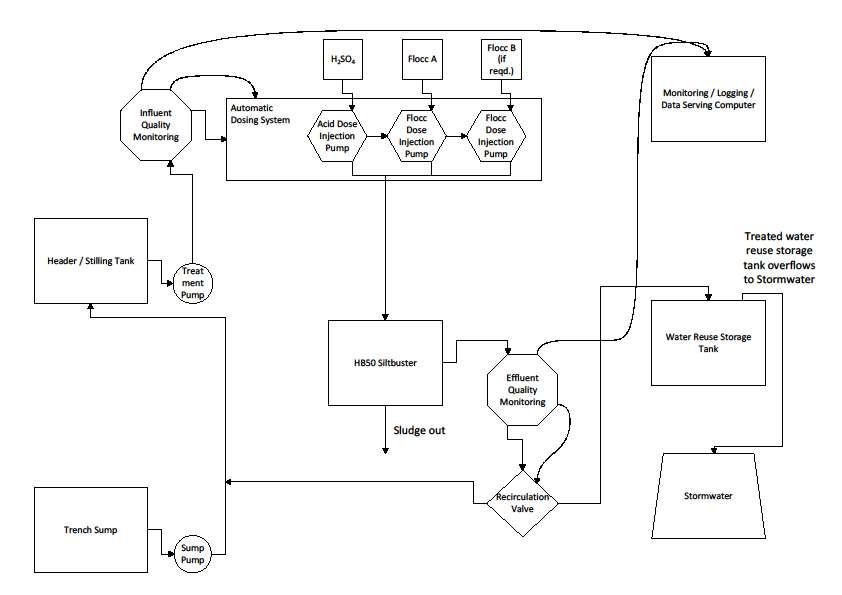
Doc. No. CRL-PAT-ENV-CON-PLN-001033
Revision: 04, Date: 21 March 2016
Project #: 2665 Doc. No. CRL-PAT-ENV-CON-PLN-001033
Client: Auckland Transport
Revision: 04, Date: 21 March 2016
A number of different dosing treatment systems were assessed, including using both flocculants with biodegradable and non-biodegradable chemical constituents. The main advantages and disadvantages of the systems are summarised in Table 2.
Table 2 Comparison of different chemical treatment systems
Option
1) HB50
Siltbuster with dosing via Haloklear Sockmaster Manifold
Advantages
Cost effective dosing system
Easy and fast to mobilise (1 day)
No moving parts in dosing system –low maintenance
No hazardous liquid chemicals to spill (gel contained in socks)
Simple to operate
2) HB50
Siltbuster with active dosing system –Halokear (“nonchemical”)
“Non-Chemical” flocculent meets Council and Mana Whenua specifications
“Non-Chemical” biodegradable flocculent does not increase risk to environment if overdosing occurs.
Does not rely on accurate dosing for effectiveness / safety
“Non-Chemical” flocculent meets Council and Mana Whenua specifications
“Non-Chemical” biodegradable flocculent does not increase risk to environment if overdosing occurs.
High accuracy of dosing extracts best performance from the dosing regime
Disadvantages
Accuracy of dosing not guaranteed – tends towards overdosing in low flow situations.
Requires higher level of technical expertise to operate, and consistent monitoring
Requires additional power, pumps and sensors.
3) HB50
Siltbuster with active dosing system –Chemical (PAC, PAMs etc)
High accuracy of dosing extracts best performance from the dosing regime.
Requires higher level of technical expertise to operate, and consistent monitoring
Requires additional power, pumps and sensors.
Overdosing of chemical due to malfunction or mismanagement could have more significant effects on the receiving environment.
Storage, handling and use of chemicals requires HSNO compliance and poses greatest risk in the event of a spill.
Inconsistent with Mana Whenua expectations.
Connectus Chemical Treatment Management Plan
Project #: 2665
Client: Auckland Transport
Doc. No. CRL-PAT-ENV-CON-PLN-001033
Revision: 04, Date: 21 March 2016
Based on the comparison above, the Haloklear Dual Polymer System (DPS) is proposed for primary use on the Project, in conjunction with an active electronic dosing system similar to the RST Environmental Solutions “Electronic Dosing Device” (Appendix D of this CTMP). The automatic dosing device will house the relevant additives in a series of chambers (refer to Section 3.3 of this CTMP for further details). If the Haloklear system proves to be less effective than anticipated, then the alternative chemical-based system will be implemented. Both types of treatment chemicals have had bench testing undertaken (results in Appendix B of this CTMP).
Project #: 2665
Client: Auckland Transport
Revision: 04, Date: 21 March 2016
The first stage in the treatment train is a mixing/header tank. The mixing facility serves to homogenise the influent water. Rapid changes of influent water quality are evened out so that gradual changes in water quality will be fed to the rest of the treatment train. This approach reduces the frequency and magnitude of dosing adjustments. In addition, during very low flows, the tank may be used to store water for batch processing.
After the mixing tank inline pH and Total Suspended Solids meters will gather continuous influent water quality data which will be fed to the pH and flocculent dosing system
The dosing point will be located near the inlet into the Siltbuster unit. This will ensure the Haloklear is sufficiently mixed by turbulent flows into the unit. Figure 1 shows a schematic of the treatment process.
The dosing system will consist of an automatic dosing device with a series of chambers containing the relevant additives. It is proposed to use Haloklear, which is a natural flocculant derived from Chitin. Chitin is a natural biopolymer found in crustacean shells. It replaces the use of chemical based flocculants which can have an adverse effect on the surrounding environment if left untreated, and is biodegradable. The Haloklear DPS dosing system utilises two different components - known as LBP2101 and Liquifloc. Both are supplied in liquid form. Refer Appendix C of this CTMP for further information on Haloklear.
3.3.1
Jar testing of the Haloklear flocculant mixtures on soil samples from adjacent boreholes was undertaken by RST Environmental Solutions Ltd (Appendix B of this CTMP). Testing compared the DPS (Liquid floc, and natural biopolymer) at different dosage levels, with a P50 polymer (blended biopolymer and polyaluminum chloride) and straight polyaluminum chloride (PAC). The results are provided in Appendix B of this CTMP
The results using the Haloklear DPS showed acceptable effluent clarity (NTU) levels for all samples. The testing found that the ideal dose for all samples was between 100 and 200ppm of each polymer for the soil concentrations of ~15g/L.
Table 3 summarises the types of soil material tested, and results. The influent turbidity values ranged from 100 to over 1000. The best-case resultant turbidity for each of the seven samples ranged from around 6 to 50. In terms of clarity measures, while these were not specifically assessed, it can be seen from the photographic laboratory results (Appendix B of this CTMP) that at least 100mm clarity can be achieved for all samples (the sample bottles are approximately 100mm wide).
Table 3: Summary of flocculant testing (Haloklear)
grey, fine
grey, fine SANDSTONE, weak.
weathered, dark grey fine grained SANDSTONE, extremely weak
1BH = Borehole number (from geotechnical investigations)
2Best result from all natural DPS flocculants / polymers
The results indicate that higher dosing rates improve the effectiveness of settling and the biodegradable Haloklear DPS approach is expected to achieve the 10cm clarity goal. Samples of total suspended solids were not taken but the water quality treatment goal for TSS will be confirmed during operation.
Due to the electronic dosing device, the likelihood of over dosing is negligible. The polymers are biodegradable, and therefore the risk to the receiving environment of overdoing is considered negligible. As a precaution a HaloKlear Residual Biopolymer Test Kit can be used to detect the presence of free residual biopolymer before it leaves the site. Typically, testing for residual chitosan has shown levels below 0.1mg/L (pers. communication with RST Environmental).
These results will be used to calibrate the electronic dosing device when the treatment plant first becomes operational. Monitoring results will indicate whether optimum dosing is being used.
Chemical flooculants were also tested (Poly Aluminum chloride) and Crystafloc B610H and were found to be equality effective. The results are also included within Appendix B of this CTMP
Project #: 2665
Client: Auckland Transport
3.3.2
Revision: 04, Date: 21 March 2016
If for some reason the effluent goals are not being met (despite being retreatment) the following steps will be taken:
a) Halting of all pumping from the excavation and discharges from site.
b) Assessment of system for blockages/clogging and make changes to DPS components as required (replace flocculants).
c) Re-test the effluent.
d) If the clarity is still unacceptable, then revert to a manual dosing system – with starting points of between 100 and 200ppm (as per the Jar Test).
e) Re-test the effluent and only release if less than the clarity goal.
f) Recalibrate automatic dosing device.
If results are still unacceptable, then the alternative flocculants will be investigated.
At times it may be impractical, unsafe or environmentally unsound to stop the dewatering system immediately. The Water Quality Assessment prepared by Golder (2014) identifies that the Total Suspended Solids water quality goal should be met at least 95% of the time. In these instances, discharge which does not meet this water quality goal may continue until a safe hold point in the construction program is reached. Where the effect of this discharge to the Waitemata Harbour is considered to be more than minor, an environmental incident investigation will be carried out to identify causes and prevent recurrence
The treatment system has been designed around a specific type of sediment removal tanks known as ‘Siltbusters’. These tanks use lamella clarifiers to improve sediment settling. .
The purpose of the effluent quality monitoring is to confirm the water being discharged meets the required discharge quality targets.
3.5.1
Contaminants in the influent water quality will be determined by:
The quality of the groundwater intercepted by the trench/tunnel
Rainwater falling in the trench and picking up contaminants as it travels to the sump The type and concentration of contaminants will be dependent on the nature of the geology, spoil or fill material the water comes into contact with. It should be noted that the sides of the trench will be progressively stabilised.
The small volumes of stormwater water entering the trench either directly or pumped from stockpile bunds.
Project #: 2665 Doc. No. CRL-PAT-ENV-CON-PLN-001033
Client: Auckland Transport
Revision: 04, Date: 21 March 2016
Taking this into account, the water quality classifications were established in the Water Quality Assessment by Golder (2014) and by Condition 89 of discharge permit R/REG/2014/5435 and are as follows:
1) Good (able to be discharged directly to the local stormwater network):
water clarity of 10cm or greater measured with a black disk (supported by weekly samples of TSS to demonstrate <50g/m3.
a pH between 5 and 9,
no visible TPH (sheen or odour)
2) Moderate
Does not meet the above criteria and will be retreated
3) Poor (collected in water tankers and removed off-site for treatment and discharge):
Water that is not able to be treated on-site
Water that cannot demonstrate compliance with 50 times the Australian and New Zealand Environment Conservation Council (ANZECC) Guidelines for Fresh and Marine Water Quality (2000) for the protection of 95 percent of marine water species.
The key contaminants to be monitored include Copper (total) mg/L, Zinc (total) mg/L, Lead (total) mg/L, and Total Petroleum Hydrocarbons mg/L. Table 4 summarises the ANZECC trigger values.
Table 4: ANZECC (2000) Trigger Values for copper, lead and zinc
The trigger values are not designed to be applied as discharge criteria, rather used to assess risk to identified receiving environment values. Where the water samples meet the trigger values the risk to the receiving environment can be considered low, while exceedances indicate a need to further investigate the cause and risk.
A monitoring report will be prepared 8 weeks after the WTP has been in operation and will include monitoring results and a discussion of the results against the above trigger values. The results will help determine whether further consideration of the values of the receiving environment and the risk to these is necessary (i.e. if the trigger levels are being exceeded). The monitoring report will consider in more detail the ongoing monitoring regime dependent on the results of the monitoring (refer section 3.5.2 of this CTMP for further discussion)
3.5.2
An effluent quality monitoring system will be installed after the Lamella Clarifiers to determine if the treated water meets the required discharge standards. An automatic system will be used to monitor TSS and pH. A recirculation valve will be in operation to send water back that does not meet the required standards (TSS of <50gm3 and pH of 5-7) to the start of the treatment process for retreatment.
Chemical Treatment Management Plan
Project #: 2665 Doc. No. CRL-PAT-ENV-CON-PLN-001033
Client: Auckland Transport
Revision: 04, Date: 21 March 2016
Within 30 days of the installation of the water treatment system, and prior to operation, a discharge monitoring programme, to assess the ongoing adequacy of all management practices, shall be developed and submitted to AC (Team Leader Central Monitoring) for certification. The programme will be based on consent condition 101 (refer Table 1 of this CTMP). However in accordance with condition 104, an initial monitoring report will discuss and refine the ongoing monitoring programme based on initial monitoring results (refer 3.5.3 of this CTMP).
Effluent quality monitoring will begin as soon as the WTP is operational.
Attached to this CTMP is an example of a record sheet (Appendix A) which will be used daily by site staff to record the following information:
Visual Check – check the Siltbuster inflow rate (m3/hr), depth within tank, influent clarity, presence/absence visible TPH (conspicuous oil or grease film, sheen or odour), and dosing system operation.
Carry out a water clarity test of effluent: 10cm or greater measured with a black disk
Check pH results from data logger to confirm pH is between 5 and 9
Record any notes for maintenance or additional information (e.g. ordering additional flocculant supplies).
In addition weekly samples of effluent will be taken from the water reuse storage tank (sample location for final discharge from the site), sent to an accredited laboratory and tested for:
Total Suspended Solids
Copper (total) mg/L
Zinc (total) mg/L
Lead (total) mg/L
Total Petroleum Hydrocarbons mg/L
The results will be reported as discussed below.
Monitoring reports will be prepared and forwarded to AC (Team Leader Central Monitoring) as follows:
a) Within eight weeks following the start of the monitoring (initial monitoring report)
b) Within five working days of receipt of sample results showing contaminants exceeding the agreed trigger levels
c) Ongoing at a frequency agreed
Initial Monitoring Report
The initial monitoring report will include:
a summary of the monitoring results to date;
an interpretation of those results and suggestions for improvement to the site operations were required;
a programme for ongoing monitoring including the reporting of results; and
water treatment plant maintenance program
Connectus Chemical Treatment Management Plan
Project #: 2665 Doc. No. CRL-PAT-ENV-CON-PLN-001033
Client: Auckland Transport
Non-conforming result report
Revision: 04, Date: 21 March 2016
Within five working days of receipt of sample results showing contaminants exceeding the agreed trigger levels an investigation shall be undertaken to determine why exceedances were detected and to identify any additional source controls or treatment required.
The results of this investigation will be sent in a report format to AC (Team Leader Central Monitoring).
Regular Monitoring Reports
The frequency and content of the regular monitoring reports will be determined in the initial monitoring report.
Project #: 2665
Client: Auckland Transport
Revision: 04, Date: 21 March 2016
The water treatment additives will be stored in CSA 4 and active and frequent monitoring by assigned personnel will allow for early identification of any flocculant overdose or spills.
Where the manual addition of flocculants may be required during phase 1 of the trench excavation, (approximately 3 months duration) this will only be undertaken by appropriately trained staff. During phase 2 of the trench excavation (approximately 17 months duration) there is little risk of overdosing occurring due to the automated dosing system. Environmental harm from an overdose or spill is minimised due to a bio-degradable flocculant being used
Chemicals will be managed in accordance with Connectus 020-E012-100 Hazardous Substances & Dangerous Goods Procedure. A 020-F028-100 Hazardous Substances & Dangerous Goods Register will be developed prior to the chemicals coming to site.
Active and frequent monitoring by assigned personnel allows for early identification of any leakages or overdosing during rainfall events. Therefore action can be taken quickly to mitigate any spills or changes in water quality when discharging back into the drainage systems.
The water treatment plant and equipment will be maintained in accordance with the manufacturer’s instructions and in accordance with the Inspection and Test Plan that will be developed for operation of the WTP. In addition to regular maintenance the performance of the plant will be verified daily using the monitoring record sheet contained in Appendix A of this CTMP.
Both substances used within the DPS system are supplied in liquid form. A Project Emergency Spill Response Plan (ESRP) has been developed to set out spill management procedures for the duration of the works. The ESRP is appended to the Project CEMP as Appendix T.
Project #: 2665
Client: Auckland Transport
Revision: 04, Date: 21 March 2016
This section provides details of the person or bodies that will hold responsibility for the long term operation and maintenance of the chemical treatment system and the organisational structure which will support this system.
As per the Project CEMP (Section 4.1.2), the Cut and Cover Construction Manager and the Environment and Sustainability Manager (ESM) will be responsible for implementation of the CTMP, including the operation and maintenance of the treatment system (Table 5)
Table 5 Roles responsible for implementation of the CTMP
Cut and Cover Construction Manager
Environment and Sustainability Manager (ESM)
Implement environmental protection measures in accordance with the contract and the CEMP and sub-plans including CTMP; and
Ensure all workers and others (e.g. subcontractors and suppliers) comply with environmental operating procedures and community relations protocols.
Manages and co-ordinates site monitoring and maintains and submits relevant reporting and records to the Auckland Council and Auckland Transport, as required;
Undertakes regular site inspections and audits to ensure compliance with the CEMP and sub-plans (including this CTMP) and consent conditions;
Input records of all environmental monitoring results to Fulcrum in relation to this CTMP;
Trains staff in site specific environmental procedures;
Coordinates environmental emergency responses; and
Manages maintenance and monitoring of the effectiveness of erosion and sediment controls, stormwater and water treatment devices and other control devices
Project #: 2665
Client: Auckland Transport
Revision: 04, Date: 21 March 2016
Site:
Connectus Chemical Treatment Management Plan
Project #: 2665 Doc. No. CRL-PAT-ENV-CON-PLN-001033
Client: Auckland Transport
Revision: 04, Date: 21 March 2016

Settling analysis on soil core samples provided by Aecom (August 2015)
Prepared by: Danny Williams IXOM – Water Chemicals
Sediment control from earthworks and infrastructure development sites has an ongoing focus as a potential source of environmental pollution and a risk to New Zealand native species and habitats in waterways.
Particle size, soil chemistry and rainfall intensity are the main factors influencing the settling rate of suspended particles in a rain event.
Bench testing of soil types likely to be encountered from sites and highlighting potential problematic soil types has been beneficial in alerting consent issuing authorities to aid in enforcing guidelines or regulations to minimise and for the most part eliminate sediment effects on ecosystems and waterways around New Zealand.
When required, the use of chemicals to assist coagulation and/or flocculation, and subsequently reduce settled water turbidity exiting a sediment pond or treatment process has shown to be very beneficial in reducing or eliminating effects on receiving waters.
The aim of the tests performed on the samples provided was to determine the settling rates of suspended solids mobilised by rainfall events and or ground water infiltration into site, and if deemed necessary the optimum treatment chemical(s) and approximate dose rate(s) to effectively settle and compact the colloidal or very fine sediment in a retention pond or suitably sized water treatment process (such as siltbuster or lamellar type device) References in this report will discuss the siltbuster or Lamellar device as the water treatment plant or “WTP”.
Coagulation and/or flocculation, settled water turbidity and pH was observed and recorded for each jar test and the results used to determine the optimum chemical and approximate dose rate (if any) for each sample provided
Each settling test was performed on 500mL samples of the suspension as used for the unassisted settling tests
Each sample was dosed with chemical, then agitated in a “Boltac” coagulation simulator for 10 seconds at 250rpm (to imitate chemical addition, followed by 1 minute at 100rpm (subsequent mixing in the front end of the settling pond or treatment plant/process), followed by 5 minutes at 30rpm (slow mixing to imitate slow agitation and minimal mixing in the front end of sediment pond or inside treatment plant settling zone), followed by settling for 10 minutes before sampling from the surface of the treated sample.
In an actual WTP we would believe this type of test regime to be indicative of similar scenario and if the WTP is sized appropriately there is likely to be considerably more settling time. However if there is the potential for significant build up of solids or reduced settling time in the WTP then this type of test regime will be more likely indicative of actual settling achieved in practice
To allow distinct measureable doses to be added to the bench tests it is generally accepted that the concentrated chemicals be diluted before addition.
The dilution of chemicals used for the bench testing was based on the following detail as normally specified as water/waste water industry standards
24 mL of LiquiPAC (Poly aluminium chloride 33.7% or 10.1% as Al2O3) as supplied was diluted with 1L of tap water to give 1% solution as PAC.
10mL of Crystalfloc L3RC (PolyDADMAC 40% solution) as supplied was diluted with 1L of tap water to give 1% solution. The powder version of PolyDADMAC is called Crystalfloc B3H and has >90% active or approximately double the active strength of the liquid version.
Given the above dilutions the samples were tested on the basis that 1mL of the 1% solutions per litre of testing sample/suspension is equivalent to 10 parts per million (ppm or g/m3).
1g of powder Crystalfloc B610H was diluted into 1L of water and this diluted solution was used in the bench tests, 1mL of this solution dosed into 1L of sample is equivalent to 1ppm.
The samples provided had in general very mobile clay or very fine colloidal particles which remained in suspension long enough to potentially create settling issues in a WTP
Of note the pictures taken of bench tests shows the volume of settled material and the variability thereof between each sample.
The samples provided reacted very well with what we would consider to be low range dose rates of LiquiPAC or Crystalfloc L3RC (or B3H)
Three of the samples (samples 1, 2, 5) settled relatively quickly without treatment and had settled water turbidity in below 50NTU after 2 hours of settling.
Two of the samples (samples 4 and 7) settled slowly and had settled water turbidity of approximately 100NTU after 24 hours.
The last two samples (samples 3 and 6) settled very slowly and still had settled water in excess of 100NTU after 48 hours of settling.
Given the dose rates required were relatively low, we suggest that dosing LiquiPAC would be easy to control, the same system could also be used to dose a diluted solution of Crystalfloc L3RC. A smaller and or different type of dosing pump would be required for dosing neat L3RC (such as a peristaltic or piston type pump)
We would suggest that polymer dosing is installed on the plant to allow for its use as/when required
Dosing discussions/options
L3RC is relatively viscous and this is the reason for using a different dosing pump, this may make control slightly more difficult as dose rate volumes vs flow rate will be low.
LiquiPAC gave consistently lower settled water turbidity and performed well on the two “difficult to treat samples” (sample 3 and 6) in particular when combined with dosing with Crystalfloc B610H polymer.
Sample 5 settled very quickly as was predominantly fine sandstone and may not require any treatment on its own, however as there is likely to be mixture of soils in the treatment plant at any given time we would suggest that dosing is maintained throughout the project. Furthermore we suggest extra focus on the WTP when it is noted that the alluvium materials are being treated as this is when polymer dosing will definitely be required at varying rates to maintain control of the treatment plant.
It would also be strongly recommended that further testing is done on set up of the plant and throughout the project, Ixom can provide the bench testing resources as required.
1 116 <1m 18.9 Fill NonEngineered Fill
2 116 1.2-3 17.9 Tauranga Group Completely seather ASH and Lapilli TUFF, indistinctly blended
3 116 3.24.75 15.4 Tauranga Group Alluvium
SILT with some clay and minor fine sand. Light Orange an very light grey mottled, stiff, moist
1.4m: SILT with minor fine sand and clay and trace organics, very light grey with minor orange mottling, stiff, moist. Organics are small black flecks typically 0.5mm in size, and partially decomposed roots. With minor ash, and trace medium gravel appearing vesicular and up to 12 mm in size.
3.2m: Moderately thinly interbedded light grey to grey SILT and fine SAND, moist. Firm to stiff silt with trace clay and organics. Loose, uniformly graded sand with trace silt and organics. Organics are small black flecks generally 0.5mm in size, at the top of silt beds.
4 116 5.5 13.9 ECBF Completely weathered, grey, fine SANDSTONE, extremely weak. Silty fine SAND with trace to some clay, grey, low plasticity, moist, loose. With trace fine gravel.
5 116 18.25 1.1 ECBF Unweathered, grey, fine SANDSTONE, weak. Trace fine gravel, green, elongate, and medium sand, white, probably siliceous. Typically massive with minor zones, thinly bedded.
6 113 5.9 8.07* Tauranga Group ALLUVIUM (Reworked ECBF) Clay with trace silt and organics, stiff
7 113 6.8 7.17* ECBF Highly weathered, dark grey fine grained SANDSTONE, extremely weak Fine SAND with trace silt, dark grey, dense, moist, uniformly graded.
* Note that these are samples from two separate boreholes. Ordering the data by RL gives the false impression that there is a layer of Tauranga Group Aluvium beneath the first layer of ECBF.
This sample had a relatively high mobile colloidal component which remained in suspension long enough to be an issue in a WTP This sample also had a slightly low pH with untreated pH 6.23. The sample did not effectively self settle without coagulant addition, and therefore we would recommend that coagulant dosing to contain the sediment within the WTP LiquiPAC (Poly Aluminium Chloride) and Crystalfloc L3RC gave similar settled water turbidity at very low dose rates and easily achieved turbidity results below 10NTU
The sample required a relatively low dose rate of coagulant to create a floc which would settle in a WTP Furthermore over and above the optimal dose rate there was an extended range of dose rates of which effectively settled the suspended solids, so we would expect the dosing control to be relatively easy to maintain with either product across a wide range of sediment loading variability.
We would suggest that dosing of polymer is used while this material is being processed through the WTP to assist with compaction of the solids and use of the minimum amount of coagulant as possible to minimise effect on pH in particular for dosing of LiquiPAC. L3RC has little to no effect on pH, so if pH is deemed to be a control issue L3RC may be a better coagulant option for this soil type.
Untreated sample 1

This sample had a relatively high mobile colloidal component which remained in suspension long enough to be an issue in a WTP. This sample also had a slightly low pH with untreated pH 6.02.
The sample did not effectively self settle without coagulant addition, and therefore we would recommend that coagulant dosing is used to contain the sediment within the WTP
LiquiPAC (Poly Aluminium Chloride) and Crystalfloc L3RC gave similar settled water turbidity at very low dose rates and easily achieved turbidity results below 10NTU.
The sample required a relatively low dose rate of coagulant to create a floc which would settle in a WTP. Furthermore over and above the optimal dose rate there was an extended range of dose rates of which effectively settled the suspended solids, so we would expect the dosing control to be relatively easy to maintain with either product across a wide range of sediment loading variability.
We would suggest that dosing of polymer is used while this material is being processed through the WTP to assist with compaction of the solids and use of the minimum amount of coagulant as possible.
Untreated sample 2

This sample had an extremely high mobile colloidal component which remained in suspension long enough to be an issue in a WTP. This sample had an untreated pH6.73.
The sample did not effectively self settle even with coagulant addition, and therefore we would recommend that coagulant and flocculant dosing is used to contain the sediment within the WTP LiquiPAC (Poly Aluminium Chloride) and Crystalfloc L3RC gave similar settled water turbidity at mid to high range dose rates and could achieve turbidity results below 20NTU.
The sample required dosing of coagulant and flocculant to create a floc which would settle in a WTP. Over and above the optimal dose rate there was a reasonable range of dose rates of which effectively settled the suspended solids, however the balance of coagulant and flocculant would need to be adjusted according to results. We would expect the dosing control require focus to maintain results with product regime Solids removal from the bottom of the WTP will require additional discharge to avoid overfilling the WTP with solids while processing this material.
We would suggest that dosing of polymer is essential while this material is being processed through the WTP to assist with compaction of the solids and use of the minimum amount of coagulant as possible.
Untreated sample 3

This sample had a relatively high mobile colloidal component which remained in suspension long enough to be an issue in a WTP. This sample had an untreated pH6.63.
The sample did not effectively self settle without coagulant addition, and therefore we would recommend that coagulant dosing is used to contain the sediment within the WTP
LiquiPAC (Poly Aluminium Chloride) and Crystalfloc L3RC gave similar settled water turbidity at very low dose rates and easily achieved turbidity results below 10NTU.
The sample required a relatively low dose rate of coagulant to create a floc which would settle in a WTP. Furthermore over and above the optimal dose rate there was an extended range of dose rates of which effectively settled the suspended solids, so we would expect the dosing control to be relatively easy to maintain with either product across a wide range of sediment loading variability.
We would suggest that dosing of polymer is used while this material is being processed through the WTP to assist with compaction of the solids and use of the minimum amount of coagulant as possible.
Untreated sample 4
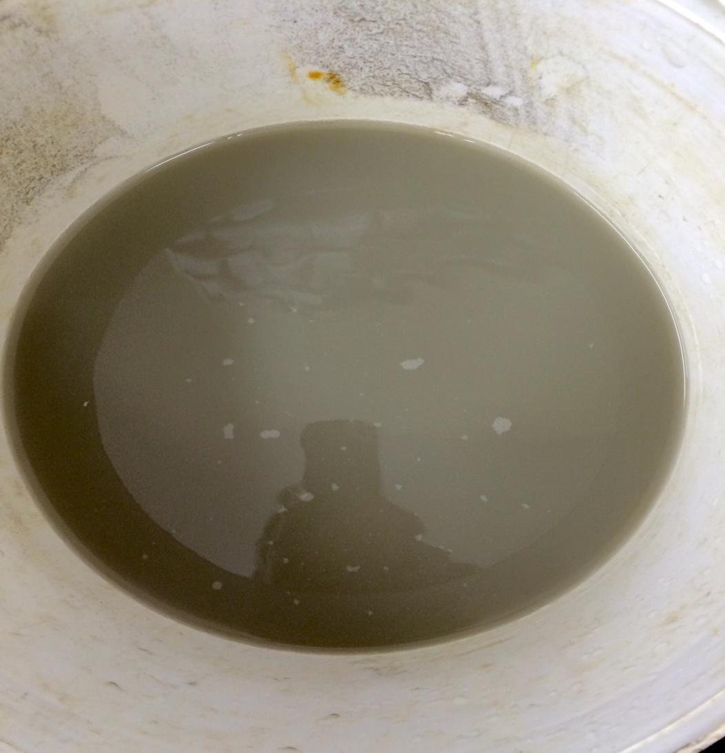
This sample had a relatively low mobile colloidal component which remained in suspension long enough to be an issue in a WTP. This sample had an untreated pH 7.33.
The sample effectively self settled without coagulant addition, however there was a small amount of colloidal material which held the settled water turbidity above 20NTU and therefore we would recommend that coagulant dosing to contain the fine sediment within the WTP.
LiquiPAC (Poly Aluminium Chloride)performed best on this sample at very low dose rates and easily achieved turbidity results below 10NTU.
The sample required a relatively low dose rate of coagulant to create a floc which would settle in a WTP. Furthermore over and above the optimal dose rate there was an extended range of dose rates of which effectively settled the suspended solids, so we would expect the dosing control to be relatively easy to maintain with either product across a wide range of sediment loading variability.
We would suggest that dosing of polymer is used while this material is being processed through the WTP to assist with compaction of the solids and use of the minimum amount of coagulant as possible.
Untreated sample 5
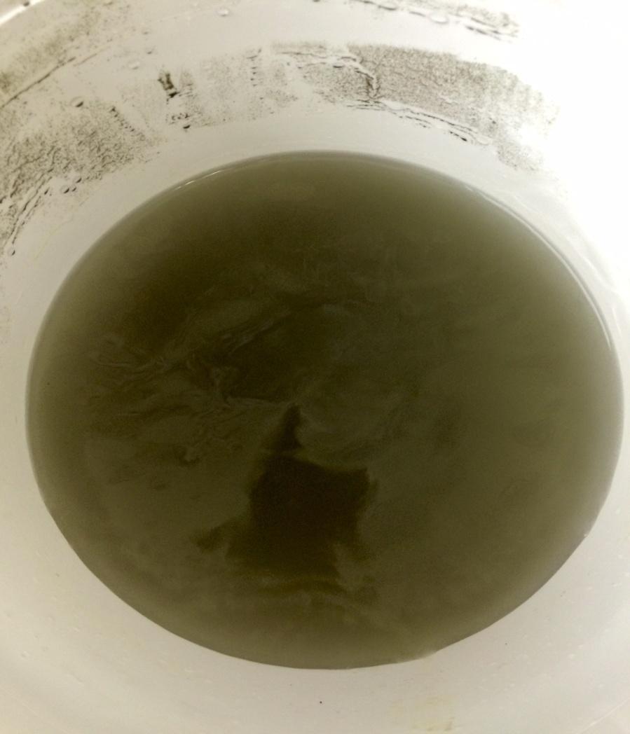
This sample had an extremely high mobile colloidal component which remained in suspension long enough to be an issue in a WTP. This sample had an untreated pH7.10.
The sample did not effectively self settle even with coagulant addition, and therefore we would recommend that coagulant and flocculant dosing is used to contain the sediment within the WTP.
LiquiPAC (Poly Aluminium Chloride) gave by far the best settled water turbidity at mid to high range dose rates and could achieve turbidity results below 20NTU only with addition of flocculant Crystalfloc L3RC did not perform very well on this sample.
The sample required dosing of coagulant and flocculant to create a floc which would settle in a WTP. Over and above the optimal dose rate there was a reasonable range of dose rates of which effectively settled the suspended solids, however the balance of coagulant and flocculant would need to be adjusted according to results. We would expect the dosing control require focus to maintain results with product regime. Solids removal from the bottom of the WTP will require additional discharge to avoid overfilling the WTP with solids while processing this material.
We would suggest that dosing of polymer is essential while this material is being processed through the WTP to assist with compaction of the solids and use of the minimum amount of coagulant as possible.
Untreated sample 6
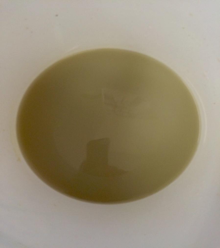
This sample had a relatively high mobile colloidal component which remained in suspension long enough to be an issue in a WTP. This sample had an untreated pH7.27.
The sample did not effectively self settle without coagulant addition, and therefore we would recommend that coagulant dosing is used to contain the sediment within the WTP.
LiquiPAC (Poly Aluminium Chloride) gave similar settled water turbidity at very low dose rates and easily achieved turbidity results below 10NTU. Crystalfloc L3RC did not perform very well on this sample.
The sample required a relatively low dose rate of coagulant to create a floc which would settle in a WTP. Furthermore over and above the optimal dose rate there was an extended range of dose rates of which effectively settled the suspended solids, so we would expect the dosing control to be relatively easy to maintain with LiquiPAC.
We would suggest that dosing of polymer is used while this material is being processed through the WTP to assist with compaction of the solids and use of the minimum amount of coagulant as possible.
Untreated sample 7
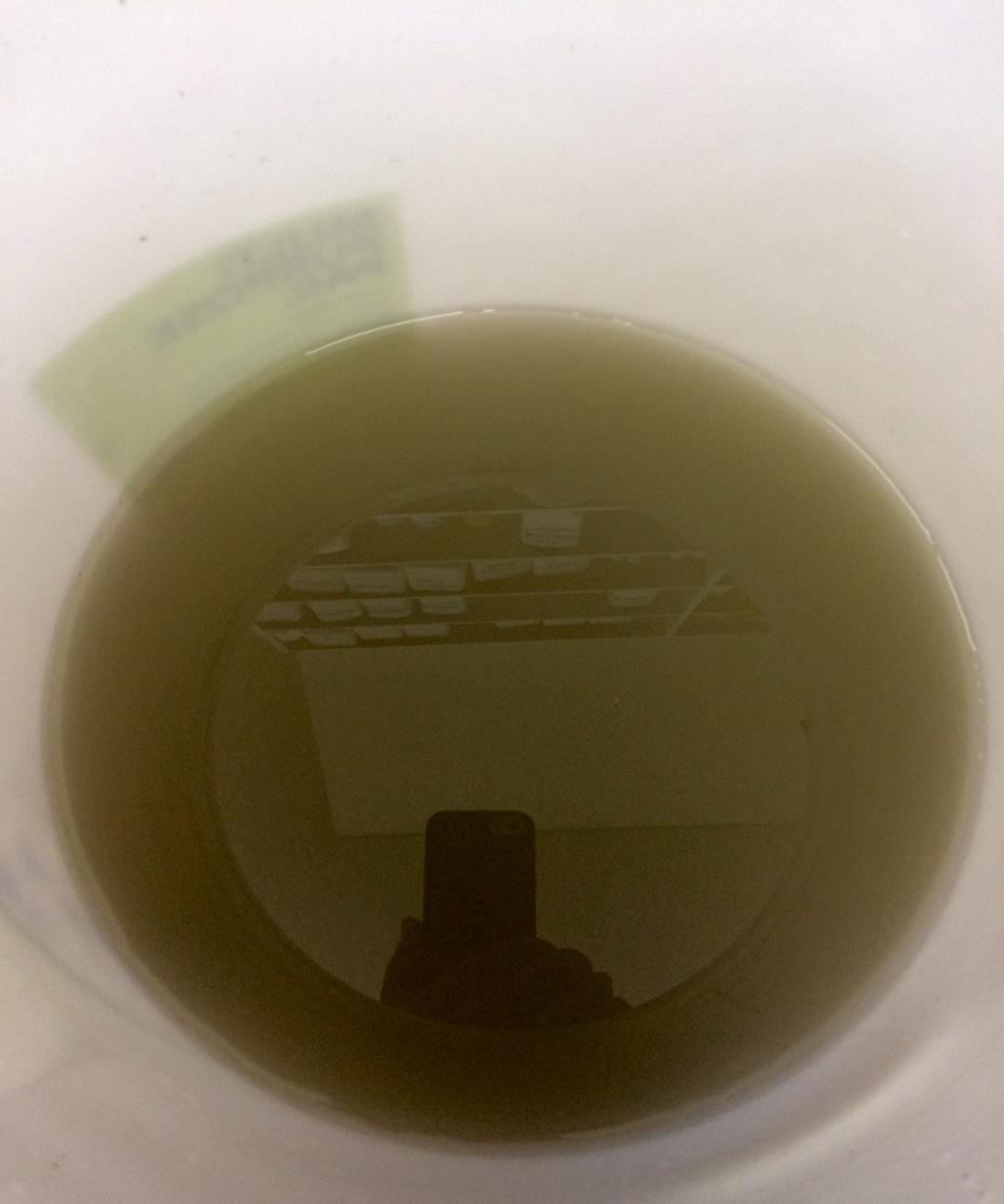
Chemically assisted Settling Test Data
Best of test results shown but other data available if required. Note this fill colour denotes optimum dose rate/range
Sample 1 Non engineered fill
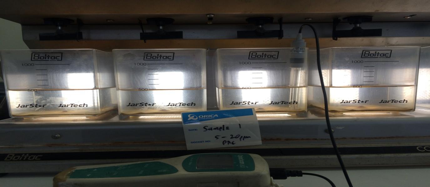
LiquiPAC 5 to 20ppm L3RC
L3RC 0.5 to 2.0ppm
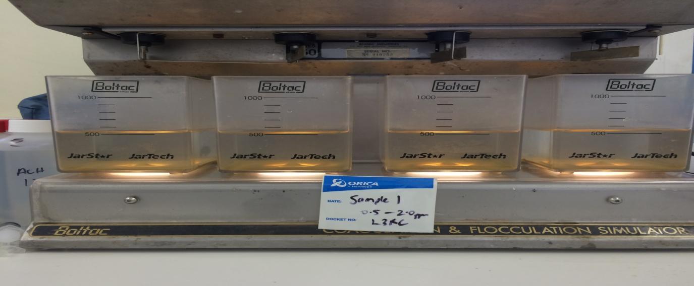
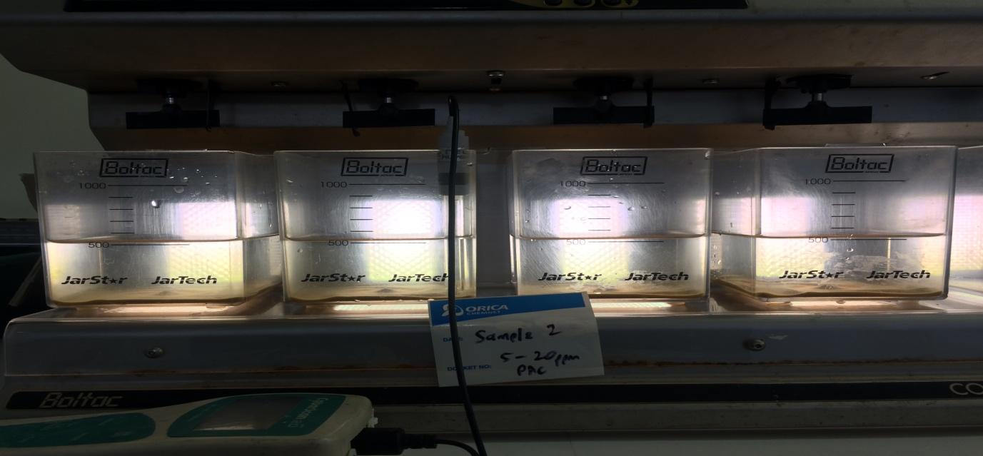
LiquiPAC 5 to 20ppm L3RC
L3RC 0.5 to 2.0ppm
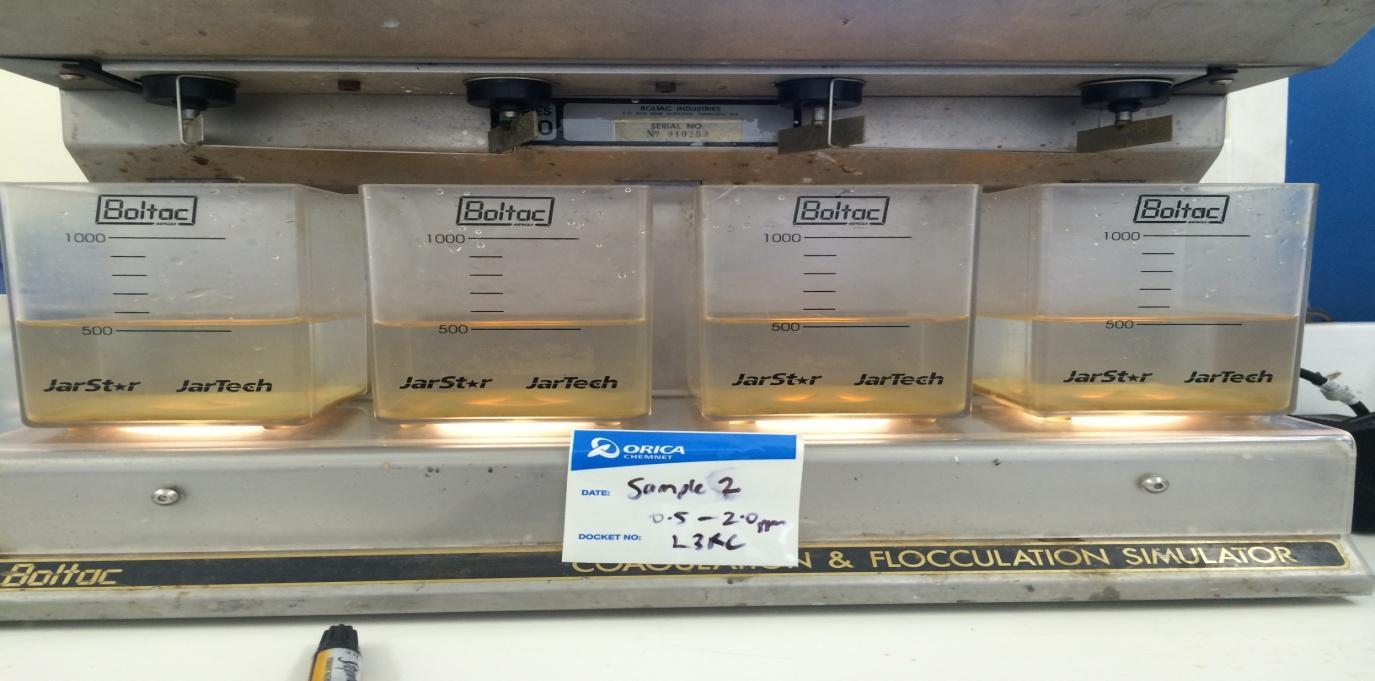
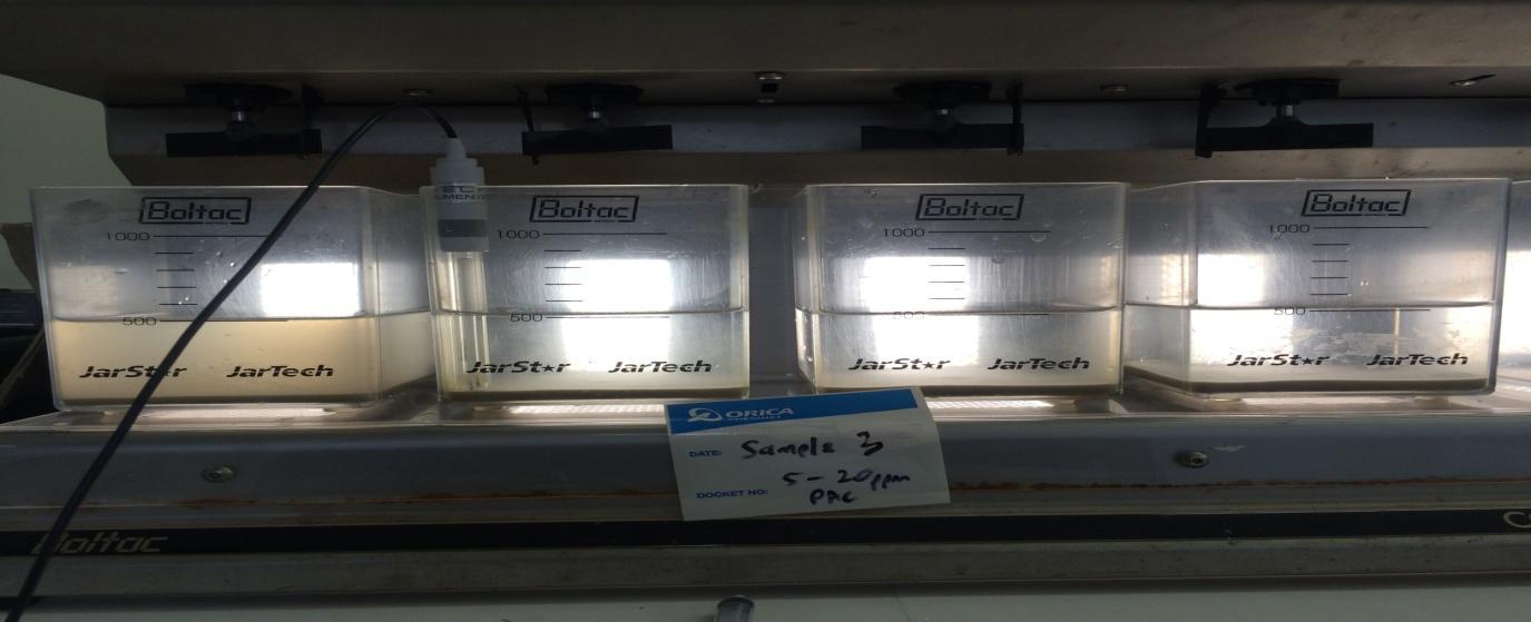
LiquiPAC 5 to 20ppm L3RC
L3RC 0.5 to 2.0ppm
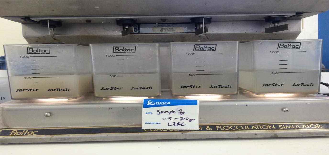
L3RC 2 to 8ppm
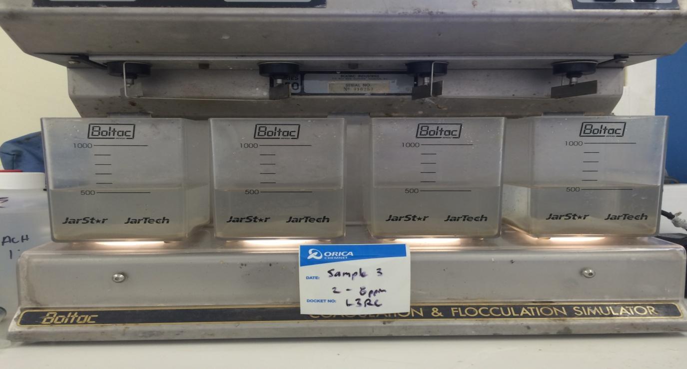
LiquiPAC 10ppm + 1 to 2ppm B610H and L3RC 2ppm + 1 to 2ppm B610H
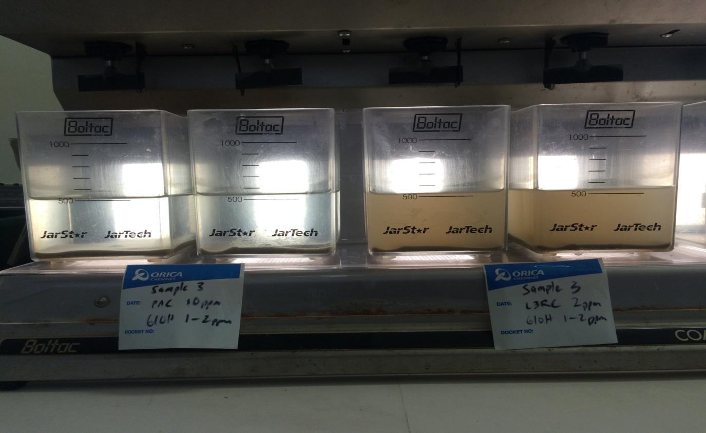
Sample 4 Completely weathered sandstone
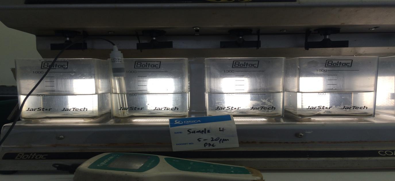
LiquiPAC 5 to 20ppm L3RC
L3RC 0.5 to 2.0ppm
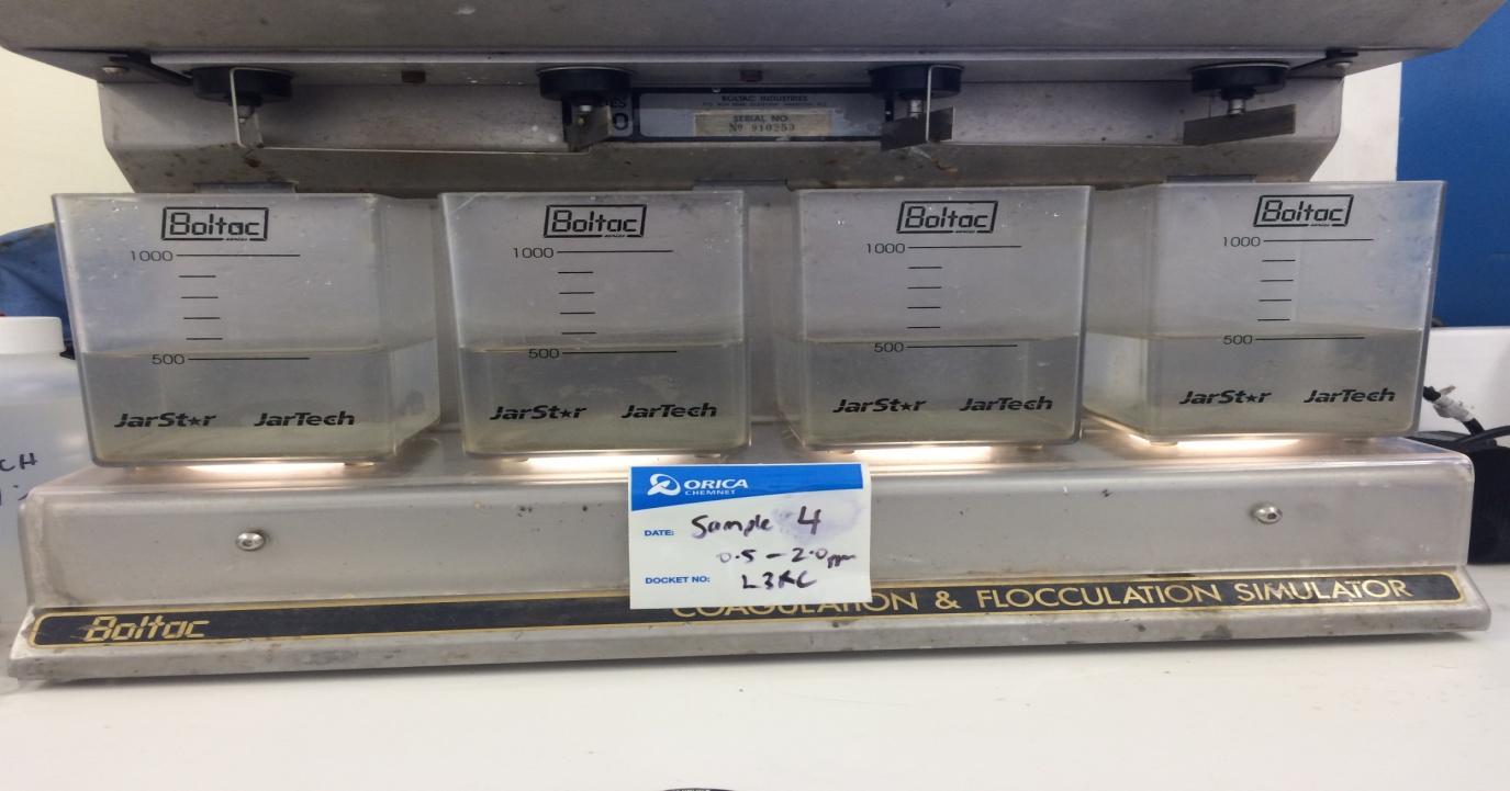
LiquiPAC 5 to 20ppm
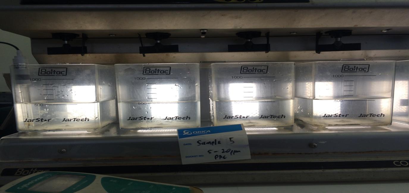
L3RC
L3RC 0.5 to 2.0ppm
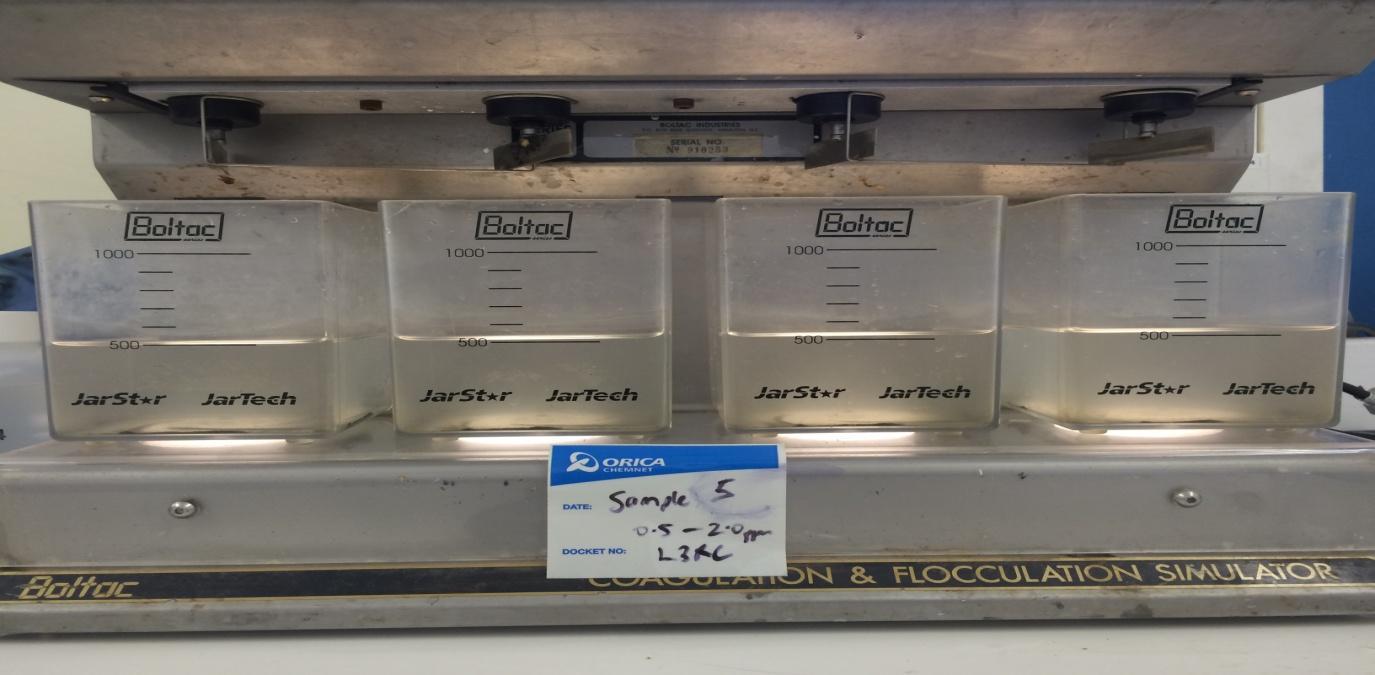
Sample 6 Alluvium reworked ECBF
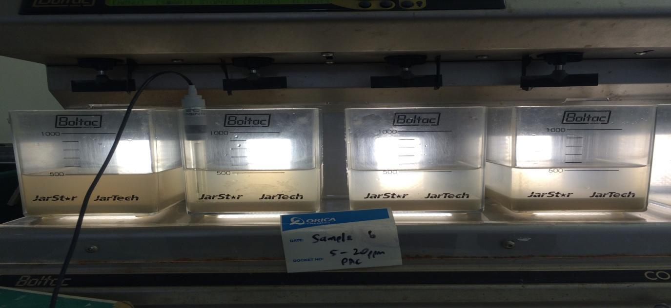
LiquiPAC 5 to 20ppm L3RC
L3RC 1 to 4ppm
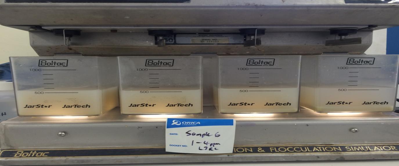
L3RC 6 to 12ppm
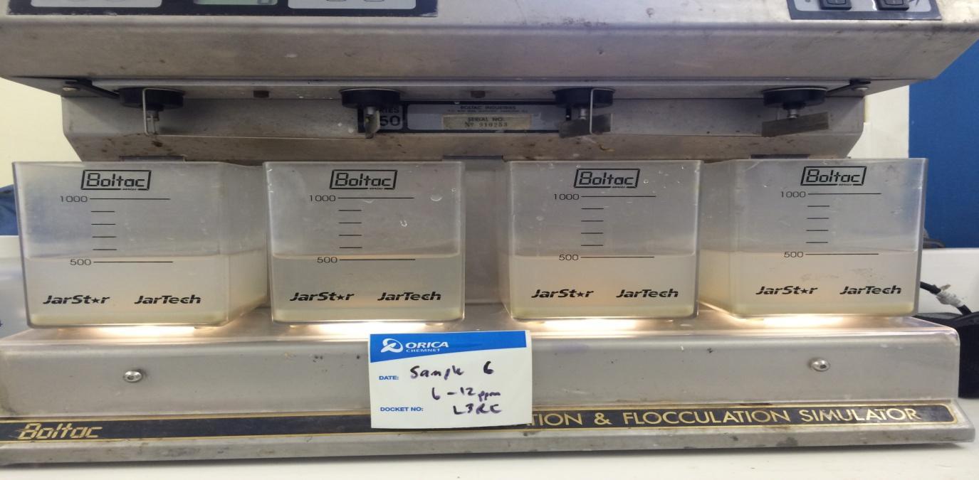
LiquiPAC 15ppm + 2 to 4ppm B610H and L3RC 6ppm + 2 to 4ppm B610H

Sample 7 Highly weathered sandstone
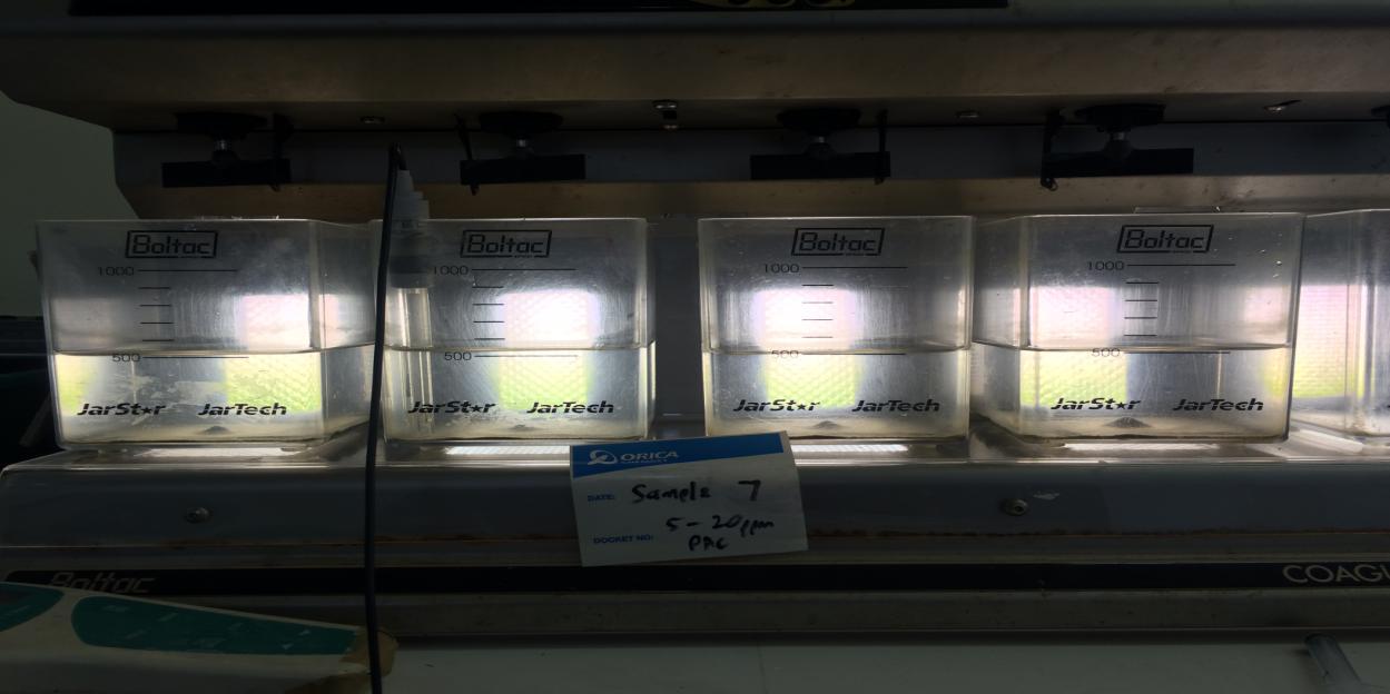
LiquiPAC 5 to 20ppm L3RC
L3RC 0.5 to 2.0ppm
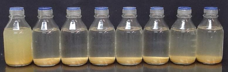
BH116(1)~15g/L
200rpmforadditions,3x500,+LF,1x500,1x200,stop. Sample
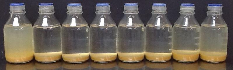
BH116(2)~15g/L
200rpm

BH116(3)~15g/L
200rpmforadditions,3x500,+LF,1x500,1x200,stop. Sample
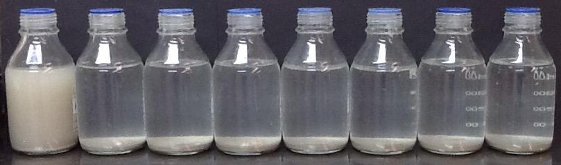
BH116(4)ECBF~15g/L
200rpm
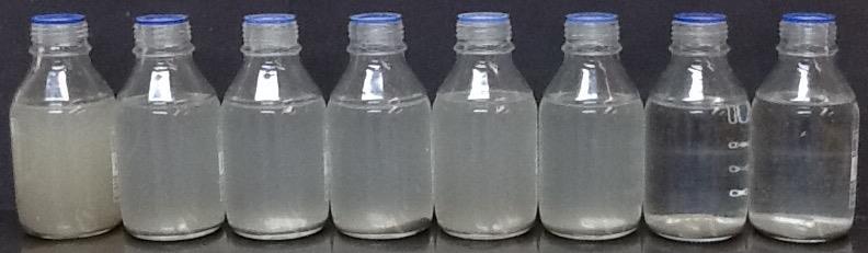
BH116(5)~15g/L
200rpmforadditions,3x500,+LF,1x500,1x200,stop. Sample
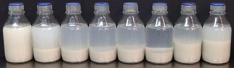
BH113(6)Alluvium~15g/L
200rpmforadditions,3x500,+LF,1x500,1x200,stop.
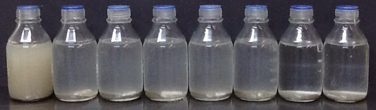
BH113(7)Sandstone
200rpmforadditions,3x500,+LF,1x500,1x200,stop.
Testing is available for any residual chitosan in water that has been treated with the dual polymer system. This looks at a standard level of 0.1mg/L chitosan and a blank sample compared to a site sample. For one site, over a four month period, residual chitosan did not register above 0.1mg/L.
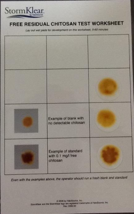
Abbreviations:
LBP = natural biopolymer, LF = liquid flocculant; P50 = blended biopolymer and polyaluminum chloride; PAC = polyaluminum chloride
Connectus Chemical Treatment Management Plan
Project #: 2665 Doc. No. CRL-PAT-ENV-CON-PLN-001033
Client: Auckland Transport
Revision: 04, Date: 21 March 2016
The best water treatment system for your business and the environment
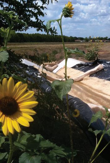
The Science of Cleaner Water


• T SS Reduc tion
• Has a proven track record in protec ting the environment and exceeding rigorou s s tate and national discharge requirement s
• Work s ef fec tively in ac tive, semi- pas sive, and pas sive treatment models
• I s cos t- ef fec tive for treating large and small sites
• 10 0% biodegradable through enz ymatic ac tivit y
• Produces no bioaccumulation
• Uses the HaloKlear DP S Jar Tes t Kit for quickly determining correc t dosage s in the field
• 10 0% PAM -free
• Work s on ALL soils
• Work s on a wide range of pH and in fresh and salt water
• Traps or flocculates some hydrocarbons , metals , and nutrient s
• Residual tes ting can be done on - site with available residual tes t kit s

HaloKlear produc t s are u sed to treat s torm, indu s trial and municipal water, including pollutant s in cons truc tion site runof f, by rever sing the proces s of water contamination through a combination of advanced, environmentally friendly, natural biopolymer technologie s .
W hen it comes to handling dir t y water, HaloKlear has built it s reputation on creating reliable, ef fec tive and safe solutions that can solve all kind s of sediment control problems HaloKlear ’s Dual Polymer Sys tem (DP S) u ses natural biopolymer s that completely biodegrade through simple enz ymatic ac tivit y, re sulting in no bioaccumulation. The primar y ac tive ingredient s are commonly u sed in the dietar y supplement and food indus tries
The HaloKlear Biopolymer Residual Te s t Kit is u sed to ensure exces s biopolymer s are not leaving the site This knowledge is comfor ting for regulator s ,contrac tor s and the general public , who can rest assured that the products are not going to cause harm to the environment .
Mos t impor tantly, HaloKlear ’s DP S has a be s t- in - clas s per formance, and has proven it self under vas tly varied conditions around the world. It is u sed in s ys tems ranging from ac tive treatment for mobile water treatment , semi- pas sive pumped water incorporating coar se filtration and geotex tile bag s , and completely pas sive models , such as bio -filtration and check dams . HaloKlear DP S is de signed to give contrac tor s and indu s tries in need of water treatment solutions the es sential tool they need to meet s tate and national discharge regulations , and as well as the new proposed EPA Ef fluent Limitation Guidelines (ELGs).
In the field, we all face the same problem – we mu s t return water to the environment that meet s discharge guidelines HaloKlear products are a complete line of cos t- ef fec tive, innovative produc t s that will meet your need s today. These produc t s are not only safe for the environment , they have helped our cu s tomer s solve their discharge problems , while enhancing projec t economic s in indu s trie s like:
• Cons truc tion
• Oil & Gas
• Mining
• Dredging
• Indu s trial Proces s Water
• Raw Was tewater Treatment
• Environmental Remediation
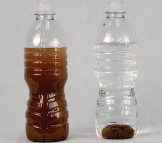
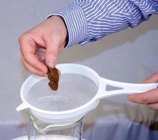
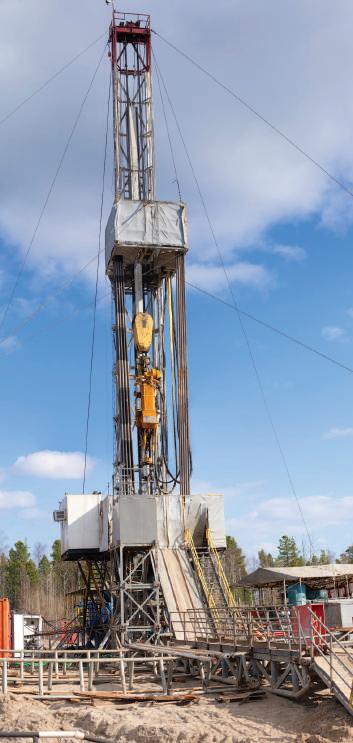
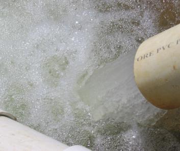
HaloKlear products achieve significant water quality results in active, semi-passive and passive treatment systems.

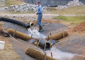
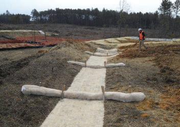
• Acrylamide-free treatment system
• Lowest maintenance requirement
• No mechanized equipment requirement
• Can reduce footprint by up to 50%
• Minimizes or eliminates need for water storage
• Actual flow range dependent on Best Management Practice (BMP) design and frequency/severity of storm events
• Uses natural filtration and settling to reduce costs
• A cost-effective model for meeting EPA & ELG requirements
• Easily applied to new and existing BMPs
• Lowest cost treatment system
• Delivers consis tent result s
• Acr ylamide -free treatment s ys tem
• Low maintenance requirement
• Low mechanized equipment requirement
Typical Results: 20-50 NTU
• Significantly reduces footprint compared to traditional ac tive treatment s ys tems
• Does not require back washing
• Requires HaloKlear SockMaster™ Manifold kit & pump; rated 10 0 - 50 0 GPM
• Low cos t compared to traditional ac tive treatment s ys tems
•
May use coar se filtration, set tling, or both to improve cos t ef fec tivenes s
• Plug - in- play a variet y of configurations including: BMP s , dewatering
• bag s , and recirculation systems.
May be u sed in conjunc tion with pas sive treatment models
• May involve contaminant and nutrient removal
• Delivers consis tent re sult s
• Acr ylamide -free treatment s ys tem
Typical Results: 10-35 NTU
• Identical footprint to traditional ac tive treatment s ys tems
• Reduced frequenc y of back washing compared to traditional ac tive treatment s ys tems
• Ac tual flow range dependent on mechanized equipment and pumping capabilities
• Can reduce operational cos ts compared to traditional ac tive treatment s ys tems.
• The u se of HaloKlear biopolymer s enhances the ef ficienc y of mos t filtration equipment used in active treatment systems, by aiding the capture of finer solid s , reducing the frequenc y of back- wash, allowing fas ter set tling of par ticles in set tling tank s , and providing solid s /contaminant s that have a lower percentage of water, which reduce s hauling and disposal costs.
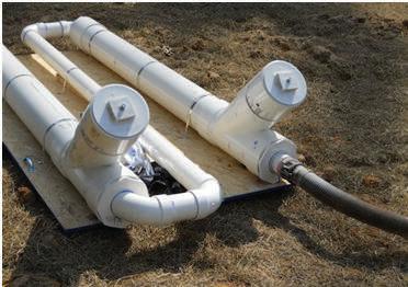
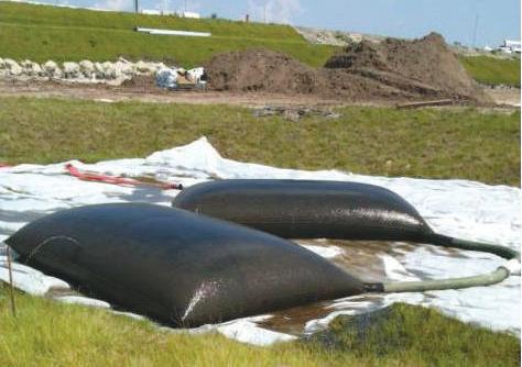
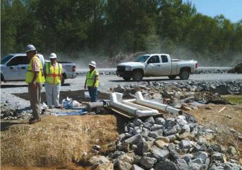
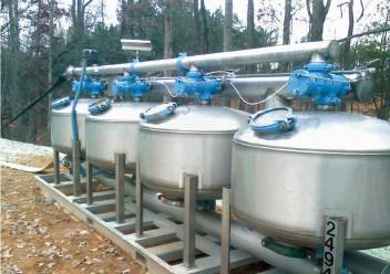
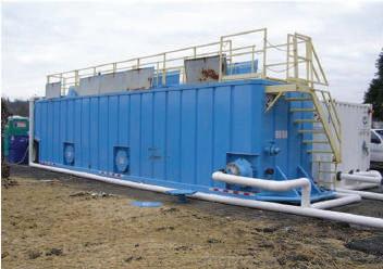
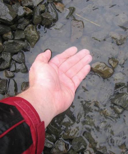
HaloKlear LiquiFloc™ and HaloKlear LBP-2101™ Liquid Formula Products
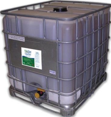
HaloKlear LiquiFloc and LBP-2101 are both available in 5-gallon buckets, 55-gallon drums, 275-gallon totes and bulk liquid. The HaloKlear LiquiFloc product is available in 1%, 2%, and 3% active concentrations, as well as in custom formulations for specific applications.
The HaloKlear product line offers a diverse selection of flocculants made up of natural bioplymers, ranging from stand-alone media to component solutions. The 100% biodegradable treatments deliver superior, consistent performance with a minimal environmental impact. HaloKlear has proven to be effective with all construction soil types and in a wide range of climates.
The treatments can be used separately or as part of the HaloKlear Dual Polymer System (DPS) to remove contaminants - such as sediments, oils, heavy metals, and nutrients - from storm and effluent water. The concentrated dry formula is more economical to ship. Consult a qualified HaloKlear technical representative or your local HaloKlear distributor for application methods and dosing information.


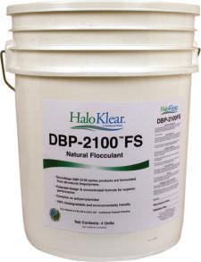
Pictures on the left show the HaloKlear MB kit, the colorcoded HaloKlear GelFloc (yellow) and the HaloKlear DBP-2100 (green) segmented socks. Each bucket has 4 individually packed socks. Dosage and metering rates can be determined using the HaloKlear DPS Jar Test Kit and by consulting a HaloKlear agent or qualified representative.
Patents: US 6,749,748
US 6,821,427
Passive model using DPS segmented socks in corrugated pipe
Semi-passive model using segmented socks and wattles
VA R IABLES
HALOKLE A R DP S
Soil Typ es The HaloKlear Formula work s on all cons truc tion soil t yp e s
Soil Samples
Dose Rate C alculation
Organic & B iodegradable
Residual Testing
Applic ation Range
There is no nee d to send soil s ample s . The HaloKlear DP S s ys tem work s on all cons truc tion soil t yp e s
Dose rate s c an b e rapidly determine d in the field with the HaloKlear DP S Jar Te s t Kit
Ye s manufacture d from natural o ccurring biopolymer s, which degrade through enz ymatic ac tivit y
HaloKlear of fer s an af fordable biopolymer re sidual te s t kit , which c an b e u se d in the field for imme diate re sult s
HaloKlear DP S c an b e applie d on pas sive, semi - pas sive, and ac tive treatment s y s tem s (Sand - M e dia , Bag s , C ar tridge s , S creens , etc )
Ac tive treatment s ys tem s will b enefit due to the t yp e of flo ck generate d (s t able and high sheer s trength), it s abilit y to ret ain finer solid s , ret ain a lower percentage of water (i.e drier solid s), and easily b e back washe d from the filter
PAMs (P OLYAC RYL AM IDES)
G R A NUL A R , P OWDER & BLOCK S
Highly soil - spe cific (10 0 s of dif ferent formulations)
T he majorit y of soil s ample s mu s t b e collec te d and shipp e d to manufac turer ’s lab for sp ecific polyacr ylamide selec tion, adding time and cos t
Dose rate c alculation mu s t b e made by manufac turer af ter soil s ample is receive d at fac tor y and analy zed , adding time and cos t
Yes derive d from p etroleum-base d produc t s
Laborator y analysis is nee de d , which c an t ake several days , adding time and cos t
Polyacr ylamide s c an only b e u se d with pas sive and semi - pas sive s ys tem s and not with ac tive treatment s ys tem s , bec au se they will u sually produce a gelatinou s flo ck which cont ains a high percentage of water and will s tick / bind to the filtration me dia (i e Sand, S creens , etc ) making it dif
to back wash and clean
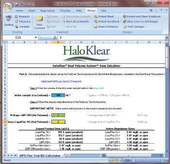
The HaloKlear DPS Jar Test Kit can be used with the HaloKlear DPS Dose Calculator to determine the proper biopolymer dose for your water clarification needs
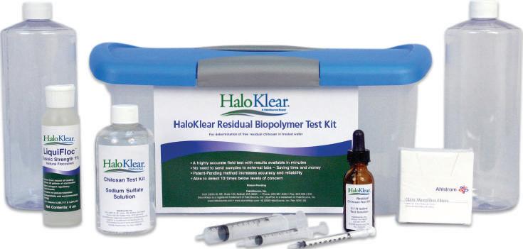


The HaloKlear DPS Dose Calculator, available for download at w w w haloklear.com /calculator, will provide the total quantit y of produc ts required in 275- gal totes, 55- gal drums, biopolymer sock s and dr y powder/ flake. Please contac t a HaloKlear representative or local distributor for pricing.
Order the HaloKlear DPS Jar Test Kit free www.haloklear.com TM
Neither HaloSource, Inc. nor the seller of this product can accept any responsibility where the product is not used according to directions, guides and for the manner in which it was intended. HaloKlear, GelFloc, LiquiFloc, DBP-2100, LBP-2101, SockMaster, and HaloSource are trademarks of HaloSource, Inc. © 2011 HaloSource, Inc.
The HaloKlear Residual Biopolymer Tes t Kit u se s proven te s t method s for detec ting the presence of free re sidual biopolymer before it can leave the job site Compared to other tes t kits, this kit improves accurac y by up to 25%. You can achieve result s without the has sle of u sing out side lab s , while ensuring you are compliant with local and federal discharge regulations
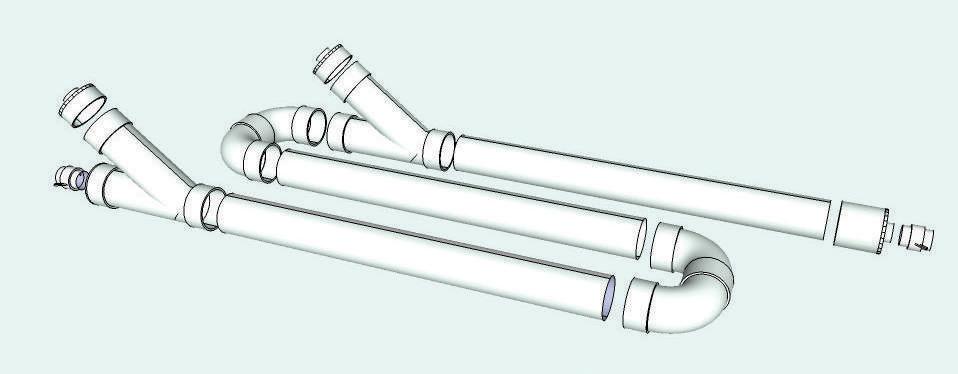
The HaloKlear SockMas ter Manifold Kit , combined with three 10 -f t sec tions of 6 - in P VC schedule - 4 0 pipe obtained locally (not included), provides all of the par t s required to quickly and easily as semble a complete HaloKlear SockMas ter Manifold The as sembled manifold hou ses the HaloKlear Dual Polymer Sys tem (DP S) sock set s during semipas sive s tormwater and was tewater treatment applications . The HaloKlear SockMas ter Manifold Kit comes complete with eas y to follow as sembly ins truc tions and diagram Please contac t a HaloKlear repre sentative or your local HaloKlear dis tributor for fur ther details and /or produc t pricing.
HaloSource, Inc. 1631 220th St. SE, STE 100, Bothell, WA 98021, USA Tel: 425-881-6464 | Fax: 425-556-4120 www.haloklear.com | www.halosource.com 1-888-98-STORM DISTRIBUTED BY
Connectus Chemical Treatment Management Plan
Project #: 2665 Doc. No. CRL-PAT-ENV-CON-PLN-001033
Client: Auckland Transport
Revision: 04, Date: 21 March 2016
This new device is set to revolutionise the Sediment and Erosion Control Industry in New Zealand. The system is designed to take all the hassle out of the old rain activated shed system.
The system is flow activated so whilst there is water running in to the pond whether from rain fall or from a pump EDD will dose the water. It can add any type of flocculent system and can run dual polymers if necessary.
EDD can manage a site up to 10 hectare.
EDD will also monitor rainfall on site and rainfall intensity and can measure the volume of water that passes through the pond.
It can send a text message if any preset limits are reached or when the flocculent is low in the tank.
Add on’s to the system include measuring total suspended solids at the inlet and outlet of the pond, pond pH plus there is provision to install other devices.
EDD has telemetry so we can transmit live data to a web site.
EDD’s systems mean that it is very easy to calibrate for any catchment size or chemical dose rater. The monitoring system means that there is less maintenance or any requirement to check the ponds and the feedback system allows for easy management.
It’s dosing system is highly accurate and so less chemical is likely to be used allowing for addition cost savings not only from less chemical but also less management time.
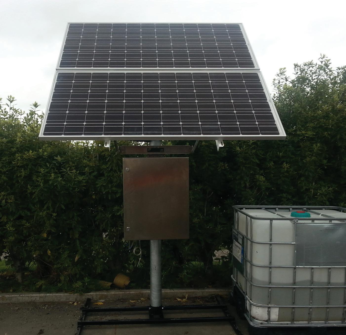
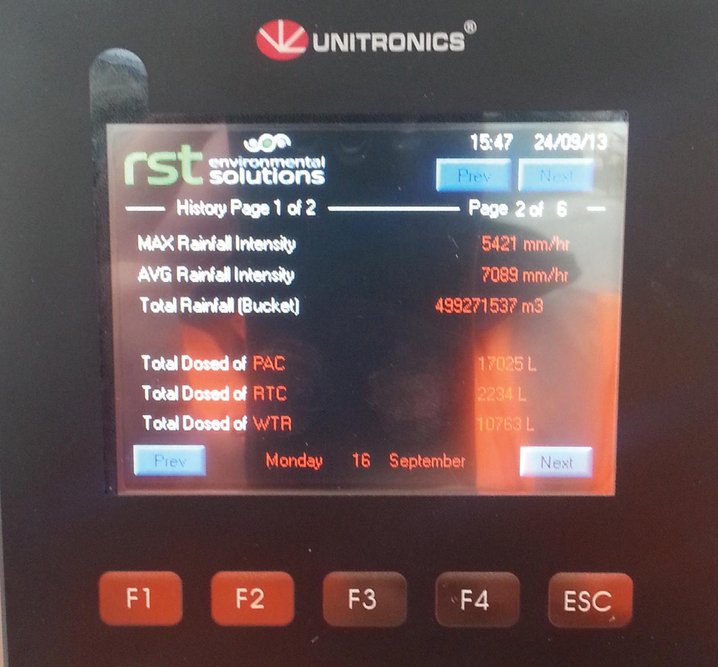
Flow activated
Accurate dosing
Can manage up to a 10ha catchment
Can sms alerts
Can post data to a website
Low flocculent alert
Can monitor: TSS pH
Rainfall
Rainfall Intensity
Other functions available

Connectus Chemical Treatment Management Plan
Project #: 2665 Doc. No. CRL-PAT-ENV-CON-PLN-001033
Client: Auckland Transport
Revision: 04, Date: 21 March 2016

Printingdate05/20/2015
Productidentifier
Tradename:HaloKlear:LBP-2101
Detailsofthesupplierofthesafetydatasheet
Manufacturer/Supplier:
HaloSourceInc
1725220thStreetSE,Suite103,Bothell,WA98021
Quality@halosourcecom
Informationdepartment:Productsafetydepartment
·Emergencytelephonenumber:
Duringnormalopeningtimes:+1(425)881-6464
800-424-9300CHEMTREC(Domestic,NorthAmerica) +1-703-527-3887CHEMTREC(International,collectcallsaccepted)
2Hazard(s)identification
Classificationofthesubstanceormixture
TheproductisnotclassifiedaccordingtotheGloballyHarmonizedSystem(GHS).
Labelelements
GHSlabelelementsVoid
·HazardpictogramsVoid
SignalwordVoid
HazardstatementsVoid
Classificationsystem: NFPAratings(scale0-4)
Otherhazards
·ResultsofPBTandvPvBassessment
·PBT:Notapplicable
vPvB:Notapplicable. 3Composition/informationoningredients
Chemicalcharacterization:Mixtures
Reviewedon05/20/2015
Printingdate05/20/2015 Reviewedon05/20/2015
Tradename:HaloKlear:LBP-2101
Descriptionoffirstaidmeasures
Generalinformation:Nospecialmeasuresrequired.
Afterinhalation:Supplyfreshair;consultdoctorincaseofcomplaints.
Afterskincontact:Generallytheproductdoesnotirritatetheskin
·Aftereyecontact:Rinseopenedeyeforseveralminutesunderrunningwater
Afterswallowing:Ifsymptomspersistconsultdoctor.
Informationfordoctor:
(Contdofpage1)
Mostimportantsymptomsandeffects,bothacuteanddelayedNofurtherrelevantinformationavailable
Indicationofanyimmediatemedicalattentionandspecialtreatmentneeded
Nofurtherrelevantinformationavailable
Extinguishingmedia
Suitableextinguishingagents:
CO2,extinguishingpowderorwatersprayFightlargerfireswithwatersprayoralcoholresistantfoam
·SpecialhazardsarisingfromthesubstanceormixtureNofurtherrelevantinformationavailable
Adviceforfirefighters
Protectiveequipment:Nospecialmeasuresrequired.
·Personalprecautions,protectiveequipmentandemergencyproceduresNotrequired
·Environmentalprecautions:Nospecialmeasuresrequired
Methodsandmaterialforcontainmentandcleaningup:
Absorbwithliquid-bindingmaterial(sand,diatomite,acidbinders,universalbinders,sawdust)
Referencetoothersections
SeeSection7forinformationonsafehandling
SeeSection8forinformationonpersonalprotectionequipment.
SeeSection13fordisposalinformation.
·Handling:
·PrecautionsforsafehandlingNospecialmeasuresrequired
Informationaboutprotectionagainstexplosionsandfires:Nospecialmeasuresrequired.
Conditionsforsafestorage,includinganyincompatibilities
Storage:
Requirementstobemetbystoreroomsandreceptacles:Nospecialrequirements
·Informationaboutstorageinonecommonstoragefacility:Notrequired
Furtherinformationaboutstorageconditions:None.
Specificenduse(s)Nofurtherrelevantinformationavailable.
·Additionalinformationaboutdesignoftechnicalsystems:Nofurtherdata;seeitem7 (Contdonpage3)
Printingdate05/20/2015
Tradename:HaloKlear:LBP-2101
Controlparameters
Reviewedon05/20/2015
(Contdofpage2)
Componentswithlimitvaluesthatrequiremonitoringattheworkplace: Theproductdoesnotcontainanyrelevantquantitiesofmaterialswithcriticalvaluesthathavetobemonitoredat theworkplace
·Additionalinformation:Theliststhatwerevalidduringthecreationwereusedasbasis
Exposurecontrols
Personalprotectiveequipment:
Generalprotectiveandhygienicmeasures:
Theusualprecautionarymeasuresforhandlingchemicalsshouldbefollowed Breathingequipment:Notrequired
·Protectionofhands:
Theglovematerialhastobeimpermeableandresistanttotheproduct/thesubstance/thepreparation.
Duetomissingtestsnorecommendationtotheglovematerialcanbegivenfortheproduct/thepreparation/the chemicalmixture
Selectionoftheglovematerialonconsiderationofthepenetrationtimes,ratesofdiffusionandthedegradation
·Materialofgloves
Theselectionofthesuitableglovesdoesnotonlydependonthematerial,butalsoonfurthermarksofqualityand variesfrommanufacturertomanufacturer.Astheproductisapreparationofseveralsubstances,theresistanceof theglovematerialcannotbecalculatedinadvanceandhasthereforetobecheckedpriortotheapplication
·Penetrationtimeofglovematerial
Theexactbreakthroughtimehastobefoundoutbythemanufactureroftheprotectiveglovesandhastobe observed.
Eyeprotection:Gogglesrecommendedduringrefilling.
·Informationonbasicphysicalandchemicalproperties
·GeneralInformation Appearance: Form: Liquid Color: White
Odor: Productspecific
·Odourthreshold: Notdetermined
pH-valueat20°C(68°F): <4
Changeincondition
Meltingpoint/Meltingrange: Undetermined
Boilingpoint/Boilingrange: 100°C(212°F)
Flashpoint: Notapplicable.
Flammability(solid,gaseous): Notapplicable
Ignitiontemperature: Decompositiontemperature: Notdetermined.
Autoigniting: Productisnotselfigniting
·Dangerofexplosion: Productdoesnotpresentanexplosionhazard
Explosionlimits: Lower: Notdetermined
Upper: Notdetermined
Printingdate05/20/2015
Tradename:HaloKlear:LBP-2101
Vaporpressureat20°C(68°F): 23hPa(17mmHg)
Densityat20°C(68°F): 099g/cm³(8262lbs/gal)
Relativedensity Notdetermined
·Vapourdensity Notdetermined
Evaporationrate Notdetermined.
Solubilityin/Miscibilitywith Water: Notmiscibleordifficulttomix
·Partitioncoefficient(n-octanol/water):Notdetermined
Viscosity: Dynamic: Notdetermined Kinematic: Notdetermined
Solventcontent:
Solidscontent: 10%
·Otherinformation Nofurtherrelevantinformationavailable
Reactivity
·Chemicalstability
Reviewedon05/20/2015
(Contdofpage3)
·Thermaldecomposition/conditionstobeavoided:Nodecompositionifusedaccordingtospecifications
PossibilityofhazardousreactionsNodangerousreactionsknown.
ConditionstoavoidNofurtherrelevantinformationavailable.
Incompatiblematerials:Nofurtherrelevantinformationavailable
·Hazardousdecompositionproducts:Nodangerousdecompositionproductsknown
Informationontoxicologicaleffects
Acutetoxicity:
Primaryirritanteffect:
·ontheskin:Noirritanteffect
·ontheeye:Noirritatingeffect
Sensitization:Nosensitizingeffectsknown.
Additionaltoxicologicalinformation:
Theproductisnotsubjecttoclassificationaccordingtointernallyapprovedcalculationmethodsforpreparations: Whenusedandhandledaccordingtospecifications,theproductdoesnothaveanyharmfuleffectsaccordingto ourexperienceandtheinformationprovidedtous.
Carcinogeniccategories
·IARC(InternationalAgencyforResearchonCancer)
Noneoftheingredientsislisted
·NTP(NationalToxicologyProgram)
Noneoftheingredientsislisted
(Contd.onpage5) US
Printingdate05/20/2015
Tradename:HaloKlear:LBP-2101
OSHA-Ca(OccupationalSafety&HealthAdministration)
Noneoftheingredientsislisted.
Toxicity
Aquatictoxicity:Nofurtherrelevantinformationavailable.
PersistenceanddegradabilityNofurtherrelevantinformationavailable
Behaviorinenvironmentalsystems:
·BioaccumulativepotentialNofurtherrelevantinformationavailable
·MobilityinsoilNofurtherrelevantinformationavailable
Additionalecologicalinformation:
Generalnotes:Generallynothazardousforwater
ResultsofPBTandvPvBassessment
PBT:Notapplicable
·vPvB:Notapplicable
OtheradverseeffectsNofurtherrelevantinformationavailable.
·Wastetreatmentmethods
·Recommendation:Smallerquantitiescanbedisposedofwithhouseholdwaste
Uncleanedpackagings: Recommendation:Disposalmustbemadeaccordingtoofficialregulations.
·UN-Number
·DOT,IMDG,IATA notregulated
UNpropershippingname
DOT,IMDG,IATA notregulated
·Transporthazardclass(es)
DOT,IMDG,IATA Class notregulated
Packinggroup
DOT,IMDG,IATA notregulated
·Environmentalhazards:
Marinepollutant: No
Specialprecautionsforuser Notapplicable.
·TransportinbulkaccordingtoAnnexIIof MARPOL73/78andtheIBCCode Notapplicable
Reviewedon05/20/2015
(Contdofpage4)
UN"ModelRegulation":US (Contdonpage6)
Printingdate05/20/2015
Tradename:HaloKlear:LBP-2101
Reviewedon05/20/2015
Safety,healthandenvironmentalregulations/legislationspecificforthesubstanceormixture
Sara
·Section355(extremelyhazardoussubstances):
Noneoftheingredientsislisted
Section313(Specifictoxicchemicallistings):
Noneoftheingredientsislisted.
TSCA(ToxicSubstancesControlAct):
Allingredientsarelisted Proposition65
Chemicalsknowntocausecancer: Noneoftheingredientsislisted
·Chemicalsknowntocausereproductivetoxicityforfemales: Noneoftheingredientsislisted
·Chemicalsknowntocausereproductivetoxicityformales: Noneoftheingredientsislisted
Chemicalsknowntocausedevelopmentaltoxicity: Noneoftheingredientsislisted.
·Carcinogeniccategories
EPA(EnvironmentalProtectionAgency) Noneoftheingredientsislisted.
TLV(ThresholdLimitValueestablishedbyACGIH) Noneoftheingredientsislisted.
NIOSH-Ca(NationalInstituteforOccupationalSafetyandHealth)
Noneoftheingredientsislisted
GHSlabelelementsVoid
HazardpictogramsVoid
·SignalwordVoid
HazardstatementsVoid
Chemicalsafetyassessment:AChemicalSafetyAssessmenthasnotbeencarriedout.
(Contdofpage5)
ThisinformationisbasedonourpresentknowledgeHowever,thisshallnotconstituteaguaranteeforanyspecific productfeaturesandshallnotestablishalegallyvalidcontractualrelationship.
DepartmentissuingSDS:Environmentprotectiondepartment
·Contact:MrsJackson
·Dateofpreparation/lastrevision05/20/2015/-
Abbreviationsandacronyms:
ADR:AccordeuropéensurletransportdesmarchandisesdangereusesparRoute(EuropeanAgreementconcerningtheInternationalCarriage ofDangerousGoodsbyRoad)
IMDG:InternationalMaritimeCodeforDangerousGoods
DOT:USDepartmentofTransportation
IATA:InternationalAirTransportAssociation
ACGIH:AmericanConferenceofGovernmentalIndustrialHygienists
EINECS:EuropeanInventoryofExistingCommercialChemicalSubstances
ELINCS:EuropeanListofNotifiedChemicalSubstances (Contdonpage7)
Printingdate05/20/2015
Tradename:HaloKlear:LBP-2101
CAS:ChemicalAbstractsService(divisionoftheAmericanChemicalSociety)
NFPA:NationalFireProtectionAssociation(USA)
HMIS:HazardousMaterialsIdentificationSystem(USA)
VOC:VolatileOrganicCompounds(USA,EU)
Reviewedon05/20/2015
(Contdofpage6)
US

Printingdate02/09/2015
Productidentifier
Tradename:LiquiFlocClassicStrength(1%)
·Detailsofthesupplierofthesafetydatasheet
·Manufacturer/Supplier: HaloSourceInc 1725220thStreetSE,Suite103,Bothell,WA98021
Quality@halosourcecom
·Informationdepartment:Productsafetydepartment
Emergencytelephonenumber:
Duringnormalopeningtimes:+1(425)881-6464
800-424-9300CHEMTREC(Domestic,NorthAmerica) +1-703-527-3887CHEMTREC(International,collectcallsaccepted)
·Classificationofthesubstanceormixture
TheproductisnotclassifiedaccordingtotheGloballyHarmonizedSystem(GHS).
Reviewedon02/09/2015
ClassificationaccordingtoDirective67/548/EECorDirective1999/45/ECNotapplicable
·Informationconcerningparticularhazardsforhumanandenvironment: Theproductdoesnothavetobelabeledduetothecalculationprocedureofinternationalguidelines
·Classificationsystem:
Theclassificationwasmadeaccordingtothelatesteditionsofinternationalsubstanceslists,andexpandedupon fromcompanyandliteraturedata
·Labelelements
·LabellingaccordingtoEUguidelines: Observethegeneralsafetyregulationswhenhandlingchemicals
Theproductisnotsubjecttoidentificationregulationsaccordingtodirectivesonhazardousmaterials.
Classificationsystem: NFPAratings(scale0-4)
0 0 0 Health=0 Fire=0 Reactivity=0
HMIS-ratings(scale0-4)
Otherhazards
ResultsofPBTandvPvBassessment
·PBT:Notapplicable
·vPvB:Notapplicable
Printingdate02/09/2015
Chemicalcharacterization:Mixtures
Description:Mixtureofthesubstanceslistedbelowwithnonhazardousadditions.
·Dangerouscomponents:Void
4First-aidmeasures
Descriptionoffirstaidmeasures
Generalinformation:Nospecialmeasuresrequired
Afterinhalation:Supplyfreshair;consultdoctorincaseofcomplaints.
Afterskincontact:Generallytheproductdoesnotirritatetheskin
·Aftereyecontact:Rinseopenedeyeforseveralminutesunderrunningwater
Afterswallowing:Ifsymptomspersistconsultdoctor
(Contdofpage1)
Informationfordoctor: Mostimportantsymptomsandeffects,bothacuteanddelayedNofurtherrelevantinformationavailable
·Indicationofanyimmediatemedicalattentionandspecialtreatmentneeded Nofurtherrelevantinformationavailable
Extinguishingmedia
Suitableextinguishingagents:
CO2,extinguishingpowderorwaterspray.Fightlargerfireswithwatersprayoralcoholresistantfoam. SpecialhazardsarisingfromthesubstanceormixtureNofurtherrelevantinformationavailable
·Adviceforfirefighters
·Protectiveequipment:Nospecialmeasuresrequired
Personalprecautions,protectiveequipmentandemergencyproceduresNotrequired Environmentalprecautions:Nospecialmeasuresrequired. Methodsandmaterialforcontainmentandcleaningup: Absorbwithliquid-bindingmaterial(sand,diatomite,acidbinders,universalbinders,sawdust)
·Referencetoothersections
SeeSection7forinformationonsafehandling
SeeSection8forinformationonpersonalprotectionequipment
SeeSection13fordisposalinformation
·Handling:
·PrecautionsforsafehandlingNospecialmeasuresrequired
Informationaboutprotectionagainstexplosionsandfires:Nospecialmeasuresrequired Conditionsforsafestorage,includinganyincompatibilities
Storage:
·Requirementstobemetbystoreroomsandreceptacles:Nospecialrequirements
·Informationaboutstorageinonecommonstoragefacility:Notrequired
Furtherinformationaboutstorageconditions:None
(Contdonpage3)
Printingdate02/09/2015 Reviewedon02/09/2015
Tradename:LiquiFlocClassicStrength(1%)
Specificenduse(s)Nofurtherrelevantinformationavailable
·Additionalinformationaboutdesignoftechnicalsystems:Nofurtherdata;seeitem7
Controlparameters
Componentswithlimitvaluesthatrequiremonitoringattheworkplace:
(Contdofpage2)
Theproductdoesnotcontainanyrelevantquantitiesofmaterialswithcriticalvaluesthathavetobemonitoredat theworkplace
·Additionalinformation:Theliststhatwerevalidduringthecreationwereusedasbasis
Exposurecontrols
Personalprotectiveequipment:
Generalprotectiveandhygienicmeasures:
Theusualprecautionarymeasuresforhandlingchemicalsshouldbefollowed
·Breathingequipment:Notrequired
·Protectionofhands:
Theglovematerialhastobeimpermeableandresistanttotheproduct/thesubstance/thepreparation
Duetomissingtestsnorecommendationtotheglovematerialcanbegivenfortheproduct/thepreparation/the chemicalmixture
Selectionoftheglovematerialonconsiderationofthepenetrationtimes,ratesofdiffusionandthedegradation
·Materialofgloves
Theselectionofthesuitableglovesdoesnotonlydependonthematerial,butalsoonfurthermarksofqualityand variesfrommanufacturertomanufacturerAstheproductisapreparationofseveralsubstances,theresistanceof theglovematerialcannotbecalculatedinadvanceandhasthereforetobecheckedpriortotheapplication
·Penetrationtimeofglovematerial
Theexactbreakthroughtimehastobefoundoutbythemanufactureroftheprotectiveglovesandhastobe observed.
Eyeprotection:Gogglesrecommendedduringrefilling.
·Informationonbasicphysicalandchemicalproperties
·GeneralInformation
·Appearance: Form: Liquid Color: Clear Odor: Pungent
·Odourthreshold: Notdetermined
pH-valueat20°C(68°F): <45
Changeincondition
Meltingpoint/Meltingrange: Undetermined
Boilingpoint/Boilingrange: 100°C(212°F)
Flashpoint: Notapplicable
Flammability(solid,gaseous): Notapplicable
·Ignitiontemperature:
Decompositiontemperature: Notdetermined (Contdonpage4)
Printingdate02/09/2015
Tradename:LiquiFlocClassicStrength(1%)
Autoigniting: Productisnotselfigniting
·Dangerofexplosion: Productdoesnotpresentanexplosionhazard
Explosionlimits: Lower: Notdetermined. Upper: Notdetermined
·Vaporpressureat20°C(68°F): 23hPa(17mmHg)
Densityat20°C(68°F): 1.1g/cm³(9.18lbs/gal)
Relativedensity Notdetermined
·Vapourdensity Notdetermined
Evaporationrate Notdetermined
Solubilityin/Miscibilitywith Water: Notmiscibleordifficulttomix
·Partitioncoefficient(n-octanol/water):Notdetermined
Viscosity:
Dynamic: Notdetermined. Kinematic: Notdetermined
·Solventcontent:
Organicsolvents: 00%
Otherinformation Nofurtherrelevantinformationavailable.
·Reactivity
·Chemicalstability
Reviewedon02/09/2015
(Contdofpage3)
·Thermaldecomposition/conditionstobeavoided:Nodecompositionifusedaccordingtospecifications
PossibilityofhazardousreactionsNodangerousreactionsknown
ConditionstoavoidNofurtherrelevantinformationavailable.
Incompatiblematerials:Nofurtherrelevantinformationavailable
·Hazardousdecompositionproducts:Nodangerousdecompositionproductsknown
Informationontoxicologicaleffects
Acutetoxicity: Primaryirritanteffect: ontheskin:Noirritanteffect
·ontheeye:Noirritatingeffect
·Sensitization:Nosensitizingeffectsknown
Additionaltoxicologicalinformation: Theproductisnotsubjecttoclassificationaccordingtointernallyapprovedcalculationmethodsfor preparations: Whenusedandhandledaccordingtospecifications,theproductdoesnothaveanyharmfuleffectsaccordingto ourexperienceandtheinformationprovidedtous
(Contd.onpage5) USA
Printingdate02/09/2015
Tradename:LiquiFlocClassicStrength(1%)
Carcinogeniccategories
IARC(InternationalAgencyforResearchonCancer)
Noneoftheingredientsislisted
·NTP(NationalToxicologyProgram)
Noneoftheingredientsislisted
·OSHA-Ca(OccupationalSafety&HealthAdministration)
Noneoftheingredientsislisted
Toxicity
Aquatictoxicity:Nofurtherrelevantinformationavailable
PersistenceanddegradabilityNofurtherrelevantinformationavailable
·Behaviorinenvironmentalsystems:
·BioaccumulativepotentialNofurtherrelevantinformationavailable
·MobilityinsoilNofurtherrelevantinformationavailable
Additionalecologicalinformation:
Generalnotes:Generallynothazardousforwater
ResultsofPBTandvPvBassessment
·PBT:Notapplicable
·vPvB:Notapplicable
OtheradverseeffectsNofurtherrelevantinformationavailable
Wastetreatmentmethods
Recommendation:Smallerquantitiescanbedisposedofwithhouseholdwaste
·Uncleanedpackagings:
·Recommendation:Disposalmustbemadeaccordingtoofficialregulations
UN-Number
DOT,IMDG,IATA notregulated
·UNpropershippingname
·DOT,IMDG,IATA notregulated
Transporthazardclass(es)
DOT,IMDG,IATA Class notregulated
·Packinggroup
·DOT,IMDG,IATA notregulated
Environmentalhazards: Marinepollutant: No
Reviewedon02/09/2015
(Contdofpage4)
(Contdonpage6) USA
Printingdate02/09/2015
Tradename:LiquiFlocClassicStrength(1%)
Specialprecautionsforuser Notapplicable
·TransportinbulkaccordingtoAnnexIIof MARPOL73/78andtheIBCCode Notapplicable
UN"ModelRegulation": -
Reviewedon02/09/2015
(Contdofpage5)
·Safety,healthandenvironmentalregulations/legislationspecificforthesubstanceormixture
·Sara
Section355(extremelyhazardoussubstances):
Noneoftheingredientsislisted.
Section313(Specifictoxicchemicallistings):
Noneoftheingredientsislisted
TSCA(ToxicSubstancesControlAct):
Allingredientsarelisted Proposition65
·Chemicalsknowntocausecancer: Noneoftheingredientsislisted
·Chemicalsknowntocausereproductivetoxicityforfemales: Noneoftheingredientsislisted
Chemicalsknowntocausereproductivetoxicityformales: Noneoftheingredientsislisted.
Chemicalsknowntocausedevelopmentaltoxicity: Noneoftheingredientsislisted
·Carcinogeniccategories
EPA(EnvironmentalProtectionAgency)
Noneoftheingredientsislisted
TLV(ThresholdLimitValueestablishedbyACGIH)
Noneoftheingredientsislisted
·NIOSH-Ca(NationalInstituteforOccupationalSafetyandHealth)
Noneoftheingredientsislisted
Productrelatedhazardinformations:
Observethegeneralsafetyregulationswhenhandlingchemicals
Theproductisnotsubjecttoidentificationregulationsaccordingtodirectivesonhazardousmaterials
·Chemicalsafetyassessment:AChemicalSafetyAssessmenthasnotbeencarriedout
Thisinformationisbasedonourpresentknowledge.However,thisshallnotconstituteaguaranteeforany specificproductfeaturesandshallnotestablishalegallyvalidcontractualrelationship
·DepartmentissuingSDS:Environmentprotectiondepartment
·Contact:MrsJackson
Dateofpreparation/lastrevision02/09/2015/-
(Contdonpage7) USA
Printingdate02/09/2015
Tradename:LiquiFlocClassicStrength(1%)
Abbreviationsandacronyms:
Reviewedon02/09/2015
(Contdofpage6)
ADR:AccordeuropéensurletransportdesmarchandisesdangereusesparRoute(EuropeanAgreementconcerningtheInternational CarriageofDangerousGoodsbyRoad)
IMDG:InternationalMaritimeCodeforDangerousGoods
DOT:USDepartmentofTransportation
IATA:InternationalAirTransportAssociation
ACGIH:AmericanConferenceofGovernmentalIndustrialHygienists
EINECS:EuropeanInventoryofExistingCommercialChemicalSubstances
ELINCS:EuropeanListofNotifiedChemicalSubstances
CAS:ChemicalAbstractsService(divisionoftheAmericanChemicalSociety)
NFPA:NationalFireProtectionAssociation(USA)
HMIS:HazardousMaterialsIdentificationSystem(USA) USA
Connectus
Project #: 2665
Client: Auckland Transport
Revision: 04, Date: 21 March 2016
AT and Connectus are seeking an Infrastructure Sustainability Council of Australia (ISCA) Infrastructure Sustainability (IS) Rating for the CRL Enabling Works – including the stormwater main realignment and OMS strengthening works. This Appendix details IS requirements that are different, or additional to the Project’s Consent Requirements. It is essential that these requirements are met to achieve the Project’s sustainability goals, however they are not consent requirements to be certified by Auckland Council. These IS rating requirements are included as an Appendix because they are not yet fixed. They remain subject to change as the Project’s sustainability program evolves.
Applicable ISCA requirements that relate to this CTMP are listed below along with their associated target Levels.
1 (Including CIR Dis-1.03 – 10/7/2015)
Measures to minimise adverse impacts to local receiving water quality during construction have been identified and implemented
Monitoring of water discharges and receiving waters is undertaken at appropriate intervals and at times of discharge during construction.
Monitoring of water discharges and receiving waters demonstrates no adverse impact on local receiving water environmental values.
4
4
Connectus Erosion and Sediment Control Plan
Project #: 2665
Client: Auckland Transport
Doc. No. CRL-PAT-ENV-CON-PLN-000897
Revision: 04, Date: 21 March 2016
Connectus
Project #: 2665
Client: Auckland Transport
Erosion and Sediment Control Plan
Doc. No. CRL-PAT-ENV-CON-PLN-000897
Revision: 04, Date: 21 March 2016
AT and Connectus are seeking an Infrastructure Sustainability Council of Australia (ISCA)
Infrastructure Sustainability (IS) Rating for the CRL Enabling Works – including the stormwater main realignment and OMS strengthening works. This Appendix details IS requirements that are different, or additional to the Project’s Consent Requirements. It is essential that these requirements are met to achieve the Project’s sustainability goals, however they are not consent requirements to be certified by Auckland Council. These IS rating requirements are included as an Appendix because they are not yet fixed. They remain subject to change as the Project’s sustainability program evolves.
Applicable ISCA requirements that relate to this ESCP are listed below along with their associated target Levels.
ISCA Category Target Level Construction Requirements How we aim to achieve this
DIS 1 (Including CIR Dis-1.03 – 10/7/2015)
2 Measures to minimise adverse impacts to local receiving water quality during construction have been identified and implemented AND
Monitoring of water discharges and receiving waters is undertaken at appropriate intervals and at times of discharge during construction. AND
Monitoring of water discharges and receiving waters demonstrates no adverse impact on local receiving water environmental values.
Compliance with this ESCP and the CTMP
Section 4
Section 3 of the CTMP, Appendix D
Section 3 of the CTMP, Appendix D
Additional Guidance:
In order to demonstrate "no adverse impact on local receiving water environmental values", the following would need to be achieved:
No exceedances of appropriately set water quality objectives, or
where there are exceedances of water quality objectives, incident investigations demonstrate: i. no disruption or degradation of environmental values, ii. no exceedance of licence limits, and iii. Improvements to practices have been implemented to prevent recurrence.
If water quality objectives are exceeded, the onus is on the assessor to demonstrate that this has not resulted in 'disruption to the regular uses or values of the receiving water could be evidence based on discussions with the notified entities. Examples of disruptions include closure of a recreational site, an inability to use the water for irrigation/drinking supply/stock watering or other uses, ceasing commercial fishing, or other interruptions to the ability to fully utilise the receiving water in ways it is normally used. ‘Degradation’ to the receiving water environment could be measurable through a measured change in, for example, AUSRIVAS waterway condition scores (in places it is measured through Australia), exceedances of ANZECC 2000) water quality objectives (only if the waterway was of a health already in accordance with the guideline), or noticeable changes in system ecology such as harm or reduction in numbers of native fish, macro-invertebrates or riparian vegetation.
Connectus Erosion and Sediment Control Plan
Project #: 2665 Doc. No. CRL-PAT-ENV-CON-PLN-000897
Client: Auckland Transport
Revision: 04, Date: 21 March 2016
Project #: 2665
Client: Auckland Transport
13 8/11/2015 - Via Email Ross Boswell
The Construction Support Areas are shown as having generators first I've seen of this. Those of us who lived through the Great Central Auckland Power Crisis grew heartily sick of the noise of motor generators. I would hope that the construction will use reticulated power, and that the generators are for emergency use only.
Erosion and Sediment Control Plan
Doc. No. CRL-PAT-ENV-CON-PLN-000897
Revision: 04, Date: 21 March 2016
Reticulated power supplies will be used for the construction support areas wherever possible. Generators will be required to support some of the more mobile activities and/or where is not practical to use reticulated sources.