RELAYS / SAFETY RELAYS Safety relay
MIRO SAFE+ STEP 24 without start button monitoring
– Protection-door control – Pressure-sensitive mat. control
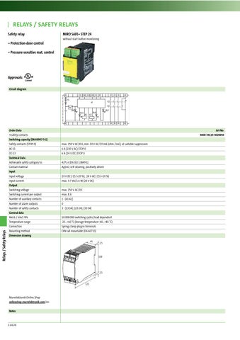
Approvals: Circuit diagram A1
S13 S14 S23 S24 X1 X2 F1
13 23 33
41
14 24 34
42
K1
a)
K2 ON
IN A
K1
K2
OUT
IN B
Relays / Safety Relays
A2
Order Data 3 safety contacts Switching capacity (EN 60947-5-1) Safety contacts (STOP 0) AC-15 DC-13 Technical Data Achievable safety category to: Contact material Input Input voltage Input current Output Switching voltage Switching current per output Number of auxiliary contacts Number of alarm outputs Number of safety contacts General data Mech./ elect. life Temperature range Connection Mounting method Dimension drawing
Art-No. 3000-33113-3020050 max. 250 V AC/8 A; min. 10 V AC/10 mA (ohm./ind.), at suitable suppression 6 A (230 V AC) STOP 0 6 A (24 V DC) STOP 0 4/PL e (EN ISO 13849-1) AgSnO, self cleaning, positively driven 24 V DC (-15/+20 %), 24 V AC (-15/+10 %) max. 3.7 VA/1.6 W (24 V DC) max. 250 V AC/DC max. 8 A 1 - (41-42) 0 3 - (13-14); (23-24); (33-34) 10.000.000 switching cycles/load dependent -25...+60 °C (storage temperature -40...+85 °C) Spring clamp plug-in terminals DIN-rail mountable (EN 60715) 45
2.5
100
2.5
121
Murrelektronik Online Shop onlineshop.murrelektronik.com/en Notes
1.10.26