Microgrid Technology and Engineering Application 1st Edition Li
Visit to download the full and correct content document: https://textbookfull.com/product/microgrid-technology-and-engineering-application-1st -edition-li/

More products digital (pdf, epub, mobi) instant download maybe you interests ...

Innovation and Application of Engineering Technology: Proceedings of the International Symposium on Engineering Technology and Application 1st Edition Wenxue Chen
https://textbookfull.com/product/innovation-and-application-ofengineering-technology-proceedings-of-the-internationalsymposium-on-engineering-technology-and-application-1st-editionwenxue-chen/

Energy Technology 2016 Carbon Dioxide Management and Other Technologies 1st Edition Li Li
https://textbookfull.com/product/energy-technology-2016-carbondioxide-management-and-other-technologies-1st-edition-li-li/

Reaction Engineering 1st Edition Shaofen Li
https://textbookfull.com/product/reaction-engineering-1stedition-shaofen-li/

Privacy Computing: Theory and Technology Li
https://textbookfull.com/product/privacy-computing-theory-andtechnology-li/

Industrial Oil Plant Application Principles and Green Technologies Changzhu Li
https://textbookfull.com/product/industrial-oil-plantapplication-principles-and-green-technologies-changzhu-li/

Microarray Technology Methods and Applications 1st Edition Paul C.H. Li
https://textbookfull.com/product/microarray-technology-methodsand-applications-1st-edition-paul-c-h-li/

Rehabilitation Robotics Technology and Application 1st Edition Roberto Colombo
https://textbookfull.com/product/rehabilitation-roboticstechnology-and-application-1st-edition-roberto-colombo/

Privacy Computing Theory and Technology 2nd Edition Fenghua Li
https://textbookfull.com/product/privacy-computing-theory-andtechnology-2nd-edition-fenghua-li/
Microgrid Architectures, Control and Protection Methods
Naser Mahdavi Tabatabaei
https://textbookfull.com/product/microgrid-architectures-controland-protection-methods-naser-mahdavi-tabatabaei/
Microgrid Technology and Engineering Application
Academic Press is an Imprint of Elsevier
Li Fusheng
Li Ruisheng
Zhou Fengquan
AMSTERDAM
•
BOSTON
•
HEIDELBERG
•
LONDON
•
NEW YORK
•
OXFORD
•
•
•
•
PARIS
SAN DIEGO
SAN FRANCISCO
SINGAPORE
•
SYDNEY
TOKYO
Academic Press is an imprint of Elsevier 125, London Wall, EC2Y 5AS, UK
525 B Street, Suite 1800, San Diego, CA 92101-4495, USA
225 Wyman Street, Waltham, MA 02451, USA
The Boulevard, Langford Lane, Kidlington, Oxford OX5 1GB, UK
Copyright © 2016 China Electric Power Press. Published by Elsevier Inc. All rights reserved.
No part of this publication may be reproduced or transmitted in any form or by any means, electronic or mechanical, including photocopying, recording, or any information storage and retrieval system, without permission in writing from the Publisher. Details on how to seek permission, further information about the Publisher’s permissions policies and our arrangements with organizations such as the Copyright Clearance Center and the Copyright Licensing Agency, can be found at our website: www.elsevier.com/permissions.
This book and the individual contributions contained in it are protected under copyright by the Publisher (other than as may be noted herein).
Notices
Knowledge and best practice in this field are constantly changing. As new research and experience broaden our understanding, changes in research methods, professional practices, or medical treatment may become necessary.
Practitioners and researchers must always rely on their own experience and knowledge in evaluating and using any information, methods, compounds, or experiments described herein. In using such information or methods they should be mindful of their own safety and the safety of others, including parties for whom they have a professional responsibility.
To the fullest extent of the law, neither the Publisher nor the authors, contributors, or editors, assume any liability for any injury and/or damage to persons or property as a matter of products liability, negligence or otherwise, or from any use or operation of any methods, products, instructions, or ideas contained in the material herein.
British Library Cataloguing-in-Publication Data
A catalogue record for this book is available from the British Library
Library of Congress Cataloging-in-Publication Data
A catalog record for this book is available from the Library of Congress
ISBN: 978-0-12-803598-6
For information on all Academic Press publications visit our website at http://store.elsevier.com/
Typeset by Thomson Digital
Printed and bound in the United States

Publisher: Joe Hayton
Acquisitions Editor: Lisa Reading
Editorial Project Manager: Hong Jin
Production Project Manager: Lisa Jones
Designer: Greg Harris
Foreword
With energy and environment issues becoming increasingly prominent, developing low-carbon economy and promoting ecological progress to achieve sustainability has been widely recognized all over the world, and use of clean, renewable resources has become an important strategy. To coordinate macrogrids and distributed generation (DG), and maximize the strengths of DG for economy, energy, and environment, scholars put forward the concept of “microgrid.” It is a single controllable electric power system comprising DG, load, energy storage (ES), and control devices. It can reduce feeder loss, and enhance local power supply reliability and energy efficiency.
With the development of smart grid, microgrid and its key enabling technologies are becoming a heated topic around the world. In an effort to further promote microgrid technologies and provide guidance for construction of microgrids, the authors write this book based on their practices and experience. In this book, the basic concept, key technologies, related standards, and practical design methods and principles of microgrid are comprehensively and systematically discussed, and a typical design case is presented and analyzed.
This book is organized into 11 chapters, as detailed below: Chapter 1 “Overview of Microgrid” describes the history, current status, and trends of microgrids; Chapter 2 “Composition and Classification of the Microgrid” describes the composition, operation and control modes, integration voltage, and classification of microgrids; Chapter 3 “Microgrid and Distributed Generation” introduces types of DG commonly used in microgrids; Chapter 4 “Control and Operation of the Microgrid” introduces control of connection to and disconnection from grids, operation control (three-state control, inverter control), and operation processes in grid-connected mode and islanded mode respectively; Chapter 5 “Protection of the Microgrid” discusses impacts of connection of microgrids on distribution network relay protection, microgrid protection strategies, and configuration scheme of protection for microgrids connected to distribution networks; Chapter 6 “Monitoring and Energy Management of the Microgrid” introduces composition of microgrid monitoring system, energy management, and optimized control methods; Chapter 7 “Communication of the Microgrid” introduces special requirements, design principles, and schemes of microgrid communication system; Chapter 8 “Earthing of a Microgrid” introduces microgrid earthing schemes; Chapter 9 “Harmonic Control of the Microgrid” introduces harmonic control technologies; Chapter 10 “Related Standards and Specifications” presents standards and specifications related to microgrid in and outside China; Chapter 11 “A Practical Case” introduces engineering design and test schemes by taking a specific project as example.
Given the short history of microgrid, many technologies are still under study. This book sums up only existing study results and practices. With studies on this subject going deeper, many new technologies will definitely emerge in the future, and we will amend this book accordingly.
This book is coauthored by Li Fusheng (researcher), Li Ruisheng (professorate senior engineer), and Zhou Fengquan (doctor), and Li Xianwei, Ma Hongwei, Yang Huihong, Tang Yunlong, Zhang Zhiwei, and Wang Huijuan from Smart Grid Research Center of XJ Group contributed
xi
significantly to data sorting and diagrams of the book. We also give our special thanks to Dr. Song Xiaowei from Zhongyuan University of Technology who provided a large number of references for us before writing, and Professor Yao Qinglin from Hefei University of Technology who carefully reviewed Chapter 5 “Protection of Microgrid,” and gave valuable comments and suggestions. We are also sincerely grateful to the authors of books we referred to while writing this book.
Owing to our limited knowledge and time, there may be some flaws or even errors in this book. Your comments and corrections are highly appreciated.
The Authors
August 2014
xii Foreword
Preface
The electric power system is moving into the smart grid era.
Energy efficiency, environmental friendliness, and operational security are the primary concerns for a smart grid. For the sustainability of the human society, it is a must to save nonrenewable energy and reduce emissions of carbon dioxide; to ensure grid security and stability, a proper proportion of power sources must be located in the load center so as to achieve local balance of electricity. In this context, microgrid, encompassing load, power source, and regulation, emerges.
Microgrid is one of the major forms to connect distributed clean energy to grids. Clean energy sources such as PV, wind, and energy storage are integrated into the microgrid on a household, building, or community basis, and the microgrid can centrally manage the distributed resources (DR) in the manner of “virtual power plant (VPP),” so as to adapt to the increasing penetration of distributed clean energy and improve the grids’ capability to accommodate these energy forms.
Microgrid is a major means to achieve local balance of electricity. The core of microgrid control and operation can be summed up as “independence and mutual support.” “Independence” allows the microgrid to be impervious to grid failure, and operate in islanded mode with little or no load loss, while “mutual support” means the microgrid and main grid can support each other, which not only ensures quality power supply of the microgrid, but also reduces the power transmission burden of the main grid.
Explaining technologies by case and engineering application is one of the features of this book. At present, quite a lot of books on microgrid are available. Instead of following the traditional way to introduce microgrid technologies, this book gives examples on how to analyze the impact of microgrids on traditional distribution networks. Through analysis, problems are raised and technologies are described and explained in solving the problems. Finally, the technologies are demonstrated in engineering application. This is helpful to make clear the viewpoints and provide reference for engineering application.
This book comprises 11 chapters, starting from introduction to roles and significance of microgrids, then classification, integration of DR, operation modes, control and protection, energy management, harmonic control, and earthing modes, then microgrid communication platforms, related standards, and finally analysis of a practical case. With this book, readers can get a clear picture of the concept and technologies of microgrid, and a deep understanding of microgrid engineering. It is a good book for people working on electrical system planning and design, equipment manufacture, and operation management, as well as college students and teachers of this discipline.
I have gained a lot from reading this book and therefore recommend it to you.
Guo Zhizhong Harbin Institute of Technology
August 2014
xiii
Overview of microgrid
A microgrid is a single, controllable, independent power system comprising distributed generation (DG), load, energy storage (ES), and control devices, in which DG and ES are directly connected to the user side in parallel. For the macrogrid, the microgrid can be deemed as a controlled cell; and for the user side, the microgrid can meet its unique demands, for example, less feeder loss and higher local reliability. Being capable of autonomous control, protection, and management, a microgrid can operate either in parallel with the main grid or in an intentional islanded mode.
A microgrid can be considered as a small electric power system that incorporates generation, transmission, and distribution, and can achieve power balance and optimal energy allocation over a given area, or as a virtual power source or load in the distribution network. Also, it can consist of one or more virtual power plants (VPPs) to meet the demand of a load center, which can be important offices, factories, or remote residences where the traditional way of electricity supply is expensive. Compared with traditional transmission and distribution (T&D) networks, a microgrid has a much more flexible structure.
1.1 HISTORY
In 2001, Professor R.H. Lasseter of the University of Wisconsin-Madison proposed the concept of the “microgrid.” Later, the Consortium for Electric Reliability Technology Solutions (CERTS) and the European Commission Project Micro-Grid also gave their definitions of a microgrid.
In 2002, the National Technical University of Athens (NTUA) built a small laboratory microgrid project known as the NTUA Power System Laboratory Facility for tests on the control of distributed resource (DR) and load with multiagent technology.
In 2003, the University of Wisconsin established a small laboratory microgrid (NREL Laboratory Microgrid) with a capacity of 80 kVA, for tests
1 Chapter Microgrid Technology and Engineering Application Copyright © 2016 China Electric Power Press. Published by Elsevier Inc. All rights reserved. 1
on the control of various types of DRs in different operation modes; another 480 V laboratory microgrid was established in the Walnut test site, Columbus, Ohio, for tests on the dynamic characteristics of various components of a microgrid.
In the same year, multiple demonstration projects were built across the world, including the 7.2 kV microgrid in Mad River Park, Vermont, USA; the 400 V microgrid in Kythnos Islands, Greece; as well as the Aichi, Kyotango, and Hachinohe projects in Japan.
In 2004, the CESI RICERCA test facility was built in Milan, Italy, which can be restructured into different topologies for steady-state and transientoperation tests and power quality analysis.
In 2005, the Imperial College London control and power research center was set up in London, UK, for distribution network prototype tests and load tests.
Over the same period, multiple demonstration projects were successively built all over the world, including Japan’s Sendai system (2004), Shimizu Microgrid (2005), and Tokyo Gas Microgrid (2006); Spain’s Labein Microgrid (2005); USA’s Sandia National Laboratories (2005) and Palmdale’s Clearwell Pumping Station (2006); and Germany’s Manheim Microgrid (2006).
Since 2006, the microgrid has been successively incorporated into China’s 863 Program (State High-Tech Development Plan) and 973 Program (National Basic Research Program). In 2006, Tsinghua University began studies on the microgrid and established a laboratory microgrid encompassing DG, ES, and loads utilizing the facilities in the National Key Laboratory on Power System and Generating Equipment Safety Control and Simulation under the Department of Electrical Engineering.
In 2008, Tianjin University and Hefei University of Technology conducted tests and studies on the microgrid. Tianjin University focused on scientific dispatch of various energy resources in the hope of improving energy efficiency, meeting various demands, and improving reliability, while Hefei University of Technology placed the focus on operation control and energy management.
In 2010, the State Grid Corporation of China (SGCC) built a demonstration project in Zhengzhou for study on operation control of a microgrid combining distributed PV (photovoltaic) generation and energy storage and engineering application and another in Xi’an for study on control technologies for microgrid combining distributed generation/energy storage.
2 CHAPTER 1 Overview of microgrid
In 2010, the China Southern Power Grid Company built a distributed energy supply – combined cooling and power (CCP) demonstration project in Foshan as a subject under China’s 863 Program.
1.2 CURRENT SITUATION OF MICROGRID OUTSIDE CHINA AND ANALYSIS
The world’s power sector has been facing great challenges like increasing loads, environmental issues, low energy efficiency, and users’ higher requirements on power quality. Microgrids can utilize and control DG in an effective, flexible, and smart manner, and hence, can best address these problems. Many countries are now carrying out studies on the microgrid and their own concepts and goals of a microgrid. As a new technology, the microgrid is showing distinct features in different countries.
1.2.1 USA
The United States is where the concept of “microgrid” originated, and its definition is the most authoritative among all others. The architecture proposed by CERTS consists of power electronic technologies-based micro sources with a capacity of 500 kW or below and loads, and integrates power electronic technologies-based control schemes. Power electronic technologies are indispensable to smart and flexible control and the basis for the “plug and play” and “peer to peer” control and design concepts. CERTS’s preliminary study results have been verified with the laboratory microgrid. The Department of Energy (DOE) took microgrid engineering seriously. In 2003, then US President Bush set the goal of grid modernization, that is, to widely integrate IT technologies and communication technologies into power systems to achieve grid smartness. In the later published “Grid 2030,” the DOE developed power system study and development plans for the coming decades, in which the microgrid is an important part. On the microgrid meeting convened in 2006, the DOE gave detailed accounts of its microgrid development plans. In view of grid modernization, improving reliability for critical loads, meeting various customized quality demands, minimizing the cost, and realizing smartness will be the focus of the United States’ future microgrid.
Figure 1.1 shows the microgrid model proposed by CERTS. This model shows that power electronics interfaces are provided for all micro sources, including PV, wind, small rotary machines, and various types of ESs. The core equipment is a smart static switch that controls the connection to and disconnection from the main grid. For each type of micro source, digital, smart relay protections are used to isolate the protected area from
3 1.2 Current situation of microgrid outside China and analysis
faults, and protection equipment is interconnected via special digital communication links.
1.2.2 Japan
Given the increasing energy shortage and load, Japan studied the microgrid concept with the aim of diversifying energy mix, reducing pollution, and meeting customized demands. In Japan, independent power systems based on traditional sources are also considered as a microgrid, which is a huge extension to the CERTS’s definition. On this basis, Japan has implemented multiple microgrid projects. In addition, Japanese scholars put forward the concept of Flexible Reliability and Intelligent Electrical Energy Delivery System (FRIENDS), that is, to add flexible AC transmission systems
4 CHAPTER 1 Overview of microgrid
■ FIGURE 1.1 Microgrid model proposed by CERTS.
(FACTS) to the distribution network to make full use of their advantages in quick and flexible control, optimize the energy mix of the distribution network, and meet varying power quality demands. So far, FRIENDS has become an important form of deployment of microgrids in Japan, and some researchers are considering including the system in combined heat and power systems for better environmental friendliness and higher energy efficiency. Japan has been committed to using new energy for many years. It set up the New Energy & Industrial Technology Development Organization (NEDO) to coordinate studies and use of new energy among universities, companies, and national key laboratories.
1.2.3 European Union
Considering market demands, power supply security, and environmental protection, the European Union (EU) proposed the “Smart Power Networks” program in 2005, and released the strategies in 2006. It called for efficient and close synergy of centralized generation and DG by making full use of distributed energy resource (DER), smart technologies, and advanced power electronic technologies, and called upon all sectors to actively participate in the electricity market and work together to promote the development of grids. Microgrids will be a major part of the European electricity networks thanks to its smartness and diversified energy mix. Currently, theories on operation, control, protection, security, and communications have been established and verified with the laboratory microgrid. The future focus will be more advanced control strategies, standards, and demonstration projects to build the foundation for large-scale integration of DG and transition from the traditional grid to the smart grid. Figure 1.2 shows the microgrid model proposed by the EU with the efforts of ABB, Fraunhofer IWES, and SMA (Germany); ZIV (Spain); The University of Manchester (the UK); EMforce (Holland); and NTUA (Greece).
The microgrid model shown in Figure 1.2 has a more complete structure, where not all micro sources have power electronics interfaces, all protection equipment is digital and smart, and interequipment communication is via controller area network (CAN). Centralized and decentralized monitoring is configured. In centralized monitoring, the central monitoring unit communicates with various switches, gives orders, and sets the switch action range. The monitoring mode is easy and cheap, but has the disadvantage that operation of all switches relies on the central monitoring unit, the failure of which will cause collapse of the entire protection system. A decentralized monitoring system is composed of multiple central monitoring units fulfilling different functions. When one unit fails, the others will automatically take over, thus avoiding system collapse. This mode offers high reliability but calls for more investment.
5 1.2 Current situation of microgrid outside China and analysis
■ FIGURE 1.2 Microgrid model proposed by the EU. CB, circuit breaker; SWB, switch board; G, micro source; L, load; MV, medium voltage; LV, low voltage.
Apart from the United States, Japan, and the European Union, Canada, Australia, and some other countries have also carried out studies on the microgrid. From their grid strategies, studies on, and practices in microgrid technologies, it can be clearly seen that the development of the microgrid does not represent a revolution to traditional centralized, large-scale grids, but an improvement of the power sector’s consciousness of services, energy utilization, and environmental protection. The microgrid is an important means for efficient, environment friendly, and quality power supply by large grids in the future, and hence, a beneficial enhancement to the large grid.
1.3 ANALYSIS OF CURRENT STATUS IN CHINA
China started its studies on the microgrid in 2006, later than other countries. Since this year, the microgrid has been incorporated into the national 863 Program and 973 Program:
863 Program subject in 2006: Distributed power supply system technologies, including technologies and equipment relating to integration, control, and protection of distributed power systems, microgrid technologies.
863 Program subject in 2007: Microgrid technologies, including the following:
1. Structure of microgrids interconnecting multiple energy sources, ESs, and loads and networking technologies;
2. Integration, control, and protection technologies;
6 CHAPTER 1 Overview of microgrid
3. Control technologies for connection to and disconnection from the grid, and for operation in islanded mode and grid-connected mode;
4. Related power electronics and control technologies;
5. Applicable advanced ESs and control technologies;
6. Internal and external power quality control technologies;
7. Technologies for energy exchange and coordination control between microgrid and macrogrid.
863 Program subject in 2008: distributed energy supply technologies, including the following:
1. Energy matching and control technologies;
2. Microgrid-dependent intermittent power sources and key ES technologies.
973 Program subject in 2009: basic research on distributed power supply system, including the following:
1. Operation characteristics of microgrid and its interaction with macrogrid under high penetration;
2. Theories and methodology on planning distribution systems integrating microgrids;
3. Protection and control for microgrids and distribution systems integrating microgrids;
4. Management methods for comprehensive simulation and energy optimization of distributed power systems.
Currently, many universities, research institutes, and large companies are carrying out studies on the microgrid and have constructed demonstration projects.
In 2006, Tsinghua University began studies on the microgrid and established a laboratory microgrid encompassing DG, ES, and loads utilizing the facilities in the National Key Laboratory on Power System and Generating Equipment Safety Control and Simulation under the Department of Electrical Engineering. Furthermore, Tsinghua, in collaboration with the XJ Group, set up a microgrid simulation platform, established steady-state and dynamic mathematical models of various types of DRs and operation in gridconnected mode, built a simulation environment for microgrids integrating DGs and other power systems and with bidirectional flow, carried out studies on microgrid modeling and operation characteristics analysis, development of simulation platform and operation characteristics analysis, and effects of microgrid on grid load model.
Tianjin University undertook the 973 Program project “Basic research on distributed generation systems,” and Huazhong University of Science and
7 1.3 Analysis of current status in China
Technology, Xi’an Jiaotong University, and some other organizations participated in the following eight subtopics: (1) interaction with the macrogrid under high penetration; (2) effects of distributed ES on security and stability of the microgrid; (3) optimized planning of distribution systems containing microgrids; (4) theories and technologies of protection for microgrids and distribution systems containing microgrids; (5) microgrid interconnection control and coordinated control of various DRs within the microgrid; (6) power quality analysis and control for microgrids and distribution systems containing microgrids; (7) comprehensive simulation of DG-based microgrids; (8) microgrid economic operation theories and energy optimization management methods.
Hefei University of Technology proposed a new inverter power supply for the microgrid based on the synchronous generator machine-electricity transient model, known as the virtual synchronous generator. It can serve as an uninterrupted power supply for critical loads following a microgrid failure. When the microgrid operates in parallel with the grid, the virtual synchronous generators are power controlled to adjust their output power according to dispatch orders; when the microgrid operates in islanded mode, the inverters are voltage and frequency controlled to provide reference for voltage of the microgrid.
The Institute of Electrical Engineering, Chinese Academy of Sciences, established a 200 kVA laboratory microgrid system, conducted steady-state and dynamic analysis, proposed steady-state and dynamic calculation methods and control and management strategies for microgrid islanded operation, and carried out a lot of studies and tests on control methods of DG and the smooth mode transfer of the microgrid.
Zhejiang University analyzed the active and reactive power circulating current model of parallel-connected inverters in a typical microgrid, and proposed an improved self-regulating droop factor control method considering the problem of instability of output power amplitude and frequency of such inverters adopting traditional droop control strategy.
Sichuan University proposed a multiagent-based uninterrupted substation power coordination system, in which various DRs are capable of automatic compensation for load fluctuation by adopting multiagent coordination strategy, thereby improving load tracing capability and reliability of substations.
In 2009, Zhejiang Electric Power Company developed a laboratory microgrid comprising multiple types of DGs and ESs, which can be flexibly restructured, and therefore can be used to simulate various failures and realize smooth transfer between grid-connected mode and islanded mode. It also carried out tests on various coordination control and protection technologies, quality control, and other advanced applications.
8 CHAPTER 1 Overview of microgrid
In 2010, Henan Electric Power Company and XJ Group jointly completed SGCC’s demonstration project, “Comprehensive study on operation control of microgrid containing PV and ES and engineering application” (as part of the Golden Sun Demonstration Project launched by the Ministry of Finance of the People’s Republic of China). This project, located in Henan College of Finance & Taxation, comprises a PV system of 380 kW and an ES system of 2 × 100 kW/100 kWh, and covers the dormitories and canteens in the No. 4 distribution area of the college, including three PV circuits, two ES circuits, and 32 low-voltage (LV) distribution circuits. It communicates with the dispatch center of Zhongmu Electric Power Company.
In the same year, Shaanxi Electric Power Company and the XJ Group jointly completed another demonstration project, “Study on control technologies for microgrid containing distributed generation/energy storage.” This project, located at the entrance to Xi’an China International Horticultural Exposition Park, consists of a series of trial projects including smart distribution network, DG, and microgrid, electric vehicle charging station, and experience of intelligent use of electricity, and is intended to exhibit SGCC’s new technologies and findings on smart grid to the public. In this project, a 50 kW PV power system is arranged on the shed of the electric vehicle charging station, and six wind turbine generators with an aggregate capacity of 12 kW and a 30 kW/60 kWh energy storage system are arranged around the charging station.
These two demonstration projects prove that the microgrid system can achieve optimal operation in grid-connected mode and stable operation in islanded mode, automatic transfer between the two modes, and control of power exchange with the macrogrid, all being unique to the microgrid. The two demonstration projects have been in commercial operation.
In 2010, CSG’s “Distributed energy supply – combined cooling and power demonstration project,” a subject under the 863 Program, began commercial operation. This project, located in the Power Supply Bureau of Chancheng District, Foshan, consists of three 200 kW microturbines and one lithium bromide water absorption refrigerator. The system can meet the cooling and power loads of the three buildings in the Bureau, and according to the design objective, the efficiency of primary energy will exceed 75%.
1.4 PROSPECTS
With the advanced IT and communication technologies, electric power systems will develop toward more flexible, cleaner, safer, and more economic smart grids. The smart grid is intended for power systems encompassing
9 1.4 Prospects
generation, transmission, distribution, and consumption, and allows for smart interaction between all links by developing and introducing advanced control technologies, thereby systematically optimizing electricity production, transmission, and consumption. To suit the development of the smart grid, the distribution network has to shift from passive to active, which is favorable to DG and allows for real-time participation of the generation side and user side in optimizing the power system operation. The microgrid is an effective means for an active distribution network, which will help largescale integration of DG and transition from the traditional grid to smart grid.
The use of various types of DGs and ESs in the microgrid is not only conducive to energy saving and emission reduction, but also significantly motivates the sustainability strategy in China. Compared with traditional centralized power systems, new energy-based DG can largely reduce feeder losses and save investment on T&D networks. It allows for mutual support with the macrogrid, full use of available resources and equipment, and reliable and quality supply, thereby increasing energy efficiency and grid security. In spite of a short history in China, the microgrid technology suits China’s needs to develop renewable energy and seek sustainability, and hence, in-depth studies on the microgrid are of great significance.
10 CHAPTER 1 Overview of microgrid
Composition and classification of the microgrid
This chapter introduces the composition, structure, operation, and control modes and integration voltages of the microgrid, as well as classification of microgrids by function demand, capacity, and AC/DC type.
2.1 COMPOSITION
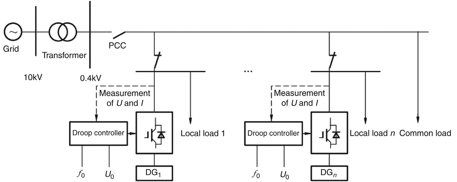
A microgrid is composed of distributed generation (DG), loads, energy storage (ES), and control devices. It acts as a single entity with respect to the grid, and connects to the grid via a single point of common coupling (PCC). Figure 2.1 shows the composition and structure of a microgrid.
1. DG: It can be various types of new energy, such as photovoltaic (PV), wind, and fuel cell; or combined heat and power (CHP) or combined cooling, heat, and power (CCHP), which provides heat for users locally, thereby increasing efficiency and flexibility of DG.
2. Loads: It includes common load and critical load.
3. ES: It includes physical, chemical, and electromagnetic forms, for storage of renewable energy, load shifting, and black-start of microgrid.
4. Controldevices: They constitute the control system for DGs, ESs, and transfer between grid-connected mode and islanded mode, facilitating real-time monitoring and energy management.
2.2 STRUCTURE
Figure 2.2 shows the three-layer microgrid control scheme implemented in the demonstration project based on “multiple microgrid structures and controls.” The top layer is the distribution network dispatch layer, which coordinates and dispatches the microgrid to maintain security and economy of the distribution network, and the microgrid is regulated and controlled by the distribution network. The middle layer is the centralized control layer. It forecasts the DG output and load demand, develops operation plans, and adjusts the plans and controls start and stop of DG, load, and ES in real-time
11 Chapter Microgrid Technology and Engineering Application Copyright © 2016 China Electric Power Press. Published by Elsevier Inc. All rights reserved.
2
■ FIGURE 2.1 Composition and structure of microgrid.
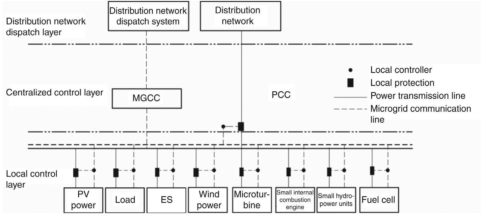
■ FIGURE 2.2 Structure of three-layer microgrid control.
based on information such as current, voltage, and power, thereby ensuring voltage and frequency stability of the microgrid. In grid-connected operation, the microgrid operates for best economic efficiency; in islanded operation, the microgrid regulates the output of DGs and consumption of loads to ensure stable and secure operation. The bottom layer, local control layer,
12 CHAPTER
Composition and classification of the microgrid
2
executes coordination of DGs, charging and discharging control of ESs, and load control within the microgrid.
2.2.1 Distribution network dispatch layer
The distribution network dispatch layer coordinates and dispatches the microgrid to keep the distribution network in a safe and economic operation, and the microgrid is regulated and controlled by the distribution network.
The microgrid acts as a single controllable and flexible entity with respect to the macrogrid.
1. It can operate either in parallel with the macrogrid or in islanded mode in the case of macrogrid failure or when necessary.
2. In special situations (e.g., an earthquake, snowstorm or flood), the microgrid can serve as reserve to the distribution network, thereby providing effective support to the macrogrid and speeding up recovery of the macrogrid from failure.
3. In case of power shortage in the macrogrid, the microgrid can shift load with its own energy storage, thereby avoiding widespread tripping of the distribution network and reducing the reserve capacity for macrogrid.
4. Under normal circumstances, the layer participates in macrogrid dispatch for best economy.
2.2.2 Centralized control layer
The centralized control layer is the microgrid control center (MGCC) and the core of the microgrid control system. It centrally manages DGs, ESs, and loads, and monitors and controls the entire microgrid. It optimizes the control strategy in real time based on the operating conditions to ensure smooth transfer between grid connection, islanding, and shutdown. In gridconnected operation, the layer regulates the microgrid for best performance; in islanded operation, the layer adjusts the DG output and load consumption to ensure stable and safe operation of the microgrid.
1. In grid-connected operation, the layer dispatches the microgrid for best economic performance and coordinates various DGs and ESs for load shifting to smooth the load curve.
2. During transfer between grid-connected mode and islanded mode, the layer coordinates the local controller to realize quick transfer.
3. In islanded operation, the layer coordinates various DGs, ESs, and loads to maintain supply to important loads and safe operation of the microgrid;
4. When the microgrid stops operation, the layer initiates black-start to rapidly resume operation.
13 2.2 Structure
2.2.3 Local control layer
The local control layer of the microgrid is composed of local protection and local controller. The local controller realizes primary regulation of frequency and voltage of DG, while local protection provides quick fault protection for the microgrid. The two work together for quick self-healing of the microgrid from faults. The DG is controlled by the MGCC and adjusts its active and reactive output according to dispatch orders.
1. The local controller controls the automatic transfer between U/f control and P/Q control.
2. The load controller rejects unimportant loads based on system frequency and voltage to ensure system security.
3. The local control layer communicates with the MGCC through weak ties. The former is responsible for microgrid transient control while the latter for steady-state control and analysis.
2.3 OPER ATION MODES
A microgrid may operate either in grid-connected or in islanded mode, and grid-connected operation is further divided into power-matched operation and power-mismatched operation according to power exchange. As shown in Figure 2.3, the microgrid is connected to the distribution network via a PCC, the active and reactive power flowing through the PCC is, respectively, ∆P and ∆Q. When ∆P = 0 and ∆Q = 0, the current through PCC is zero, indicating that the DG output and load reach a balance and no power exchange occurs between the distribution network and microgrid. This is the most economic operation mode of the microgrid, known as powermatched operation. When ∆P ≠ 0 or ∆Q ≠ 0, the current through the PCC is not zero, indicating that power exchange occurs between the distribution network and the microgrid. This mode is known as power-mismatched operation. In this mode, if ∆P < 0, the excessive active power from DGs after meeting load demand is injected to the distribution network; if ∆P > 0, the electricity from DGs is insufficient for meeting load demand, requiring
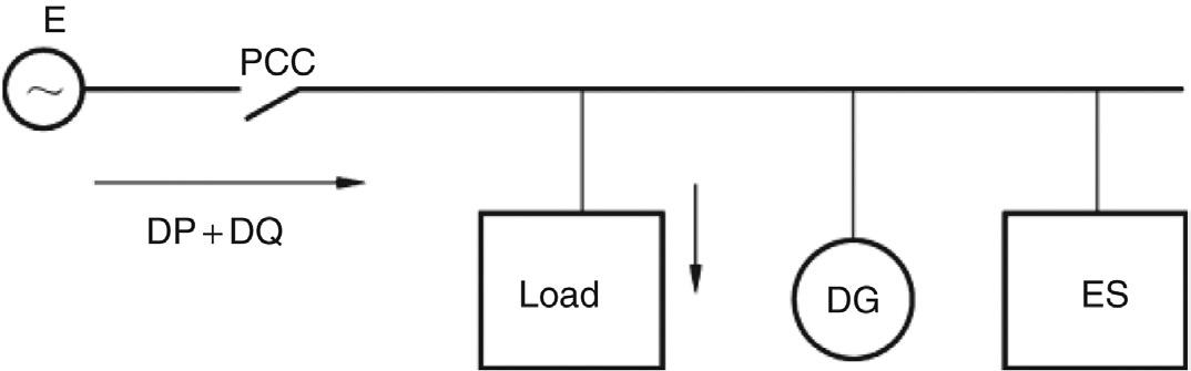
■ FIGURE 2.3 Power exchange between distribution network and microgrid.
14 CHAPTER 2 Composition and classification of the microgrid
the distribution network to provide the deficit. Likewise, reactive power is excessive if ∆Q < 0 and deficient if ∆Q > 0. All these operations are powermismatched operation variants.
2.3.1 Grid- connected operation
In grid-connected mode, the microgrid is connected to and exchanges power with the distribution system of the utility grid via PCC.
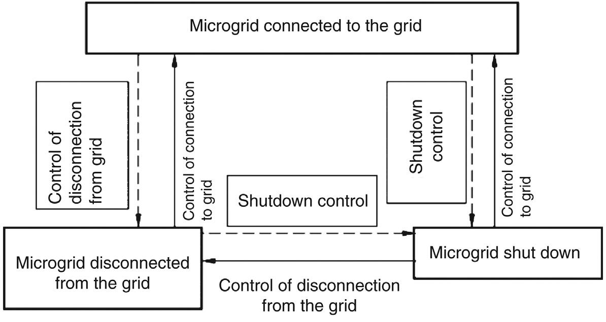
Figure 2.4 shows the schematic diagram of transfer between operation modes.
1. When the microgrid stops operation, it can transfer to grid-connected mode directly by grid connection control; when it is connected to the grid, it can be disconnected from the grid by disconnection control.
2. When the microgrid stops operation, it can transfer to islanded mode directly by disconnection control, and when it is in islanded operation, it can be connected to the grid-by-grid connection control.
3. When the microgrid operates in parallel with the grid or in islanded mode, the microgrid can be shut down by shutdown control.
2.3.2 Islanded operation
Islanded operation means that the microgrid is disconnected from the distribution system of the main grid at the PCC following a grid failure or as scheduled, and that the DGs, ESs, and loads within the microgrid operate independently. In islanded mode, since the electricity produced by the microgrid itself is generally small and insufficient to meet the demand of all
■ FIGURE 2.4 Transfer between operation modes.
15 2.3 Operation modes
loads, it is necessary to prioritize loads based on their importance and ensure uninterrupted supply to important loads.
2.4 CONTROL MODES
2.4.1
Microgrid control modes
Three microgrid control strategies are commonly used, respectively, master–slave mode, peer-to-peer mode, and combined mode. For a small microgrid, master–slave mode is most commonly used.
2.4.1.1
Master–slave mode
In master–slave mode, different DGs within a microgrid are controlled with different methods and assigned with different functions, as shown in Figure 2.5. One or more DGs act as the master while the others as the slave. In grid-connected operation, all DGs are under P/Q control. In islanded operation, the master DG switches to U/f control to provide voltage and frequency reference for other DGs. The master DG also traces load fluctuation, and therefore, its power output has to be controllable to some extent, and the DG should be able to respond fast enough to load fluctuation. The slave DGs remain under P/Q control.
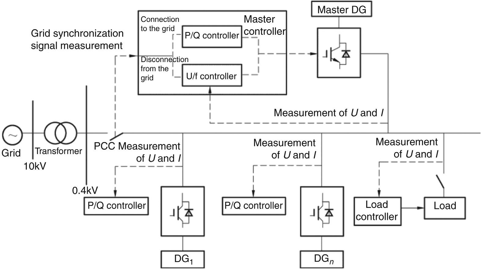
■ FIGURE 2.5 Architecture of microgrid under master–slave control.
16 CHAPTER 2 Composition and classification of the microgrid
This control mode has some disadvantages. First, with the master DG under U/f control, its voltage output is constant. To increase the power output, the only way is to increase the current output. Instantaneous load fluctuations are usually first balanced by the master DG, and therefore, it has to have a certain adjustable capacity. Second, as the system relies on the master DG to coordinate and control all slave DGs, once the master DG fails, the whole microgrid will collapse. Third, master–slave control requires accurate and timely islanding detection, while islanding detection itself is accompanied by error and time delay. Hence, without a communication channel, transfer between control strategies is likely to fail.
To enable quick transfer between control modes, the following forms of DG could be used as master DGs:
1. DGs of randomness such as PV and wind;
2. ES, microturbine, fuel cell, and other stable and easily controlled DGs; and
3. DG + ES, for example, PV + ES or PV + fuel cell.
The third form is advantageous over the first two in that it can make best use of quick charge and discharge functions of ES and the capability of DGs in maintaining islanded operation of the microgrid for an extended time. In this mode, the ES can provide power support for the microgrid immediately after it switches to islanded operation, thus effectively suppressing significant fluctuation of voltage and frequency resulting from slow dynamic response of DG.
2.4.1.2
Peer-to-peer mode
Peer-to-peer mode is a control strategy based on ideas of “plug-and-play” and “peer-to-peer” used in power electronic technologies. In this mode, all DGs in the microgrid are equal and there is no master or slave DG. All DGs participate in regulation of active power and reactive power in a preset control mode to maintain stability of the system voltage and frequency. Droop control is adopted in the peer-to-peer mode, with the architecture shown in Figure 2.6. In this mode, all DGs under droop control participate in voltage and frequency regulation of the microgrid in islanded operation. When the load changes, the changes will be automatically distributed among the DGs according to the droop factor, that is, all DGs will adjust the frequency and amplitude of their output voltage to establish a new steady state for the microgrid and finally achieve reasonable distribution of output power. The droop control model enables automatic distribution of load variations among DGs, but the voltage and frequency of the system also vary after load variation, and therefore, this control mode is actually a proportional control. The droop control model of DGs can remain unchanged for
17 2.4 Control modes
grid-connected operation and islanded operation, making it easy for smooth transfer between the two modes.
The droop control model allows for independent control of DGs according to the voltage and frequency at the PCC, thus making it possible for automatic regulation of voltage and frequency, plug-and-play of DG without communication links, and flexible and convenient deployment of the microgrid. Unlike the master–slave mode where power imbalance is compensated by the master DG, power imbalance is dynamically distributed to all DGs in the peer-to-peer mode. This kind of control is simple, reliable, and easy to deploy, but at the sacrifice of voltage and frequency stability; it is currently under laboratory test.
2.4.1.3
Combined mode
Master–slave control and peer-to-peer control have advantages and disadvantages. A microgrid may contain multiple types of DGs, such as DG of randomness (e.g., PV and wind), or stable and easily controlled DG or ES (e.g., microturbine and fuel cell). Control characteristics differ greatly for different types of DG. Apparently, a single control mode cannot meet the operation requirements of a microgrid. In view of the dispersive DGs and loads within a microgrid, different control strategies may be adopted for different types of DGs, that is, master–slave control and peer-to-peer control could be used in conjunction in a microgrid.
2.4.2 Inverter control modes
The DGs integrated to a microgrid may operate either in parallel with the grid or in islanded mode. In the former case, the DGs only need to control
18 CHAPTER 2 Composition and classification of the microgrid
■ FIGURE 2.6 Architecture of microgrid under peer-to-peer control.
their own power output to maintain balance within the microgrid. As the total capacity of a microgrid is much smaller than that of a grid, the rated voltage and frequency are supported and regulated by the grid, and the inverters are usually under P/Q control. In the latter case, the microgrid is isolated from the grid. To maintain the rated voltage and frequency within the microgrid, one or more DGs need to play the role of the grid to provide rated voltage and frequency. These DGs are usually under U/f and droop control.
2.4.2.1 P/Q control
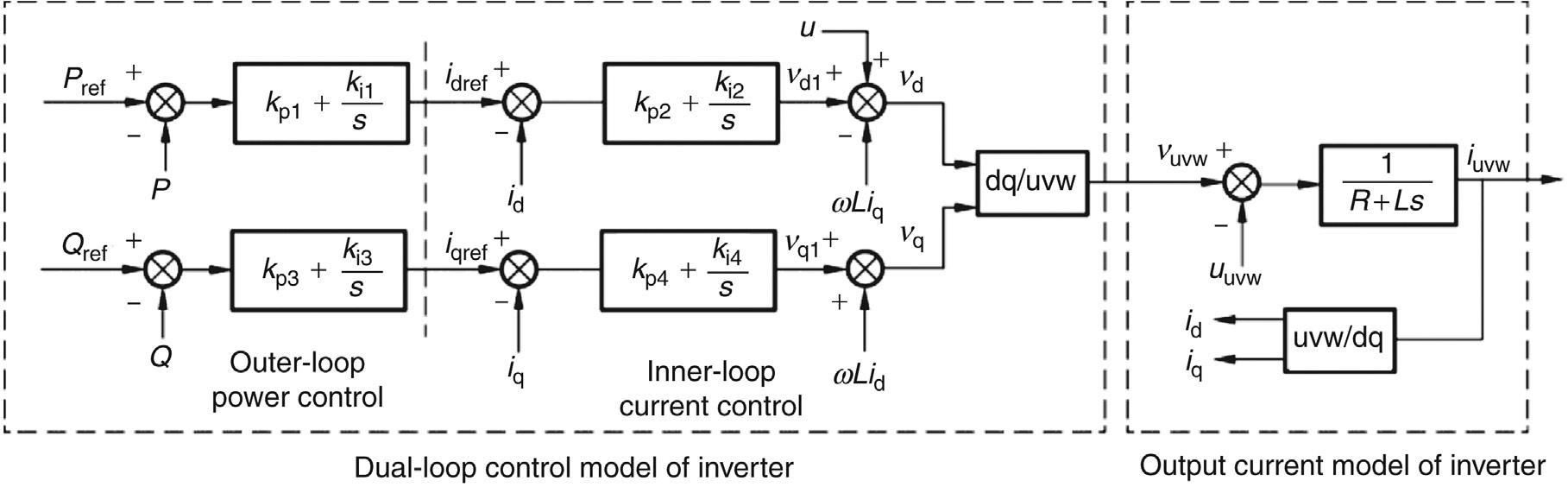
As the interface between the microgrid and macrogrid, the basic function of inverters is to control the active and reactive output. In P/Q control, the inverters can produce active power and reactive power, and the determination of reference power is the prerequisite for power control. For purpose of power control, the DGs with a mediate or small capacity can be integrated to the grid with a constant power, the grid provides rigid support for voltage and frequency, and the DGs do not participate in frequency and voltage regulation and just inject or absorb power. This can avoid direct participation of DG in the regulation of feeder voltage, thus eliminating adverse impacts on the electric power system.
P/Q control is based on the grid voltage oriented P/Q decoupled control strategy, in which the outer loop adopts power control and the inner loop adopts current control. The mathematical model is like this: the three-phase voltage is first rotated to the dq coordinate through Park transformation to get the following inverter voltage equation:
where ud and uq are the voltage at the inverter terminal, and wLiq and wLid are cross-coupling terms. They will be eliminated by feedforward compensation in subsequent control.
The PI controller is usually used for outer-loop power control. Its mathematical model is expressed as follows:
19 2.4 Control modes
vRiL i t Liu vRiL i t Liu d d d d dd d qd qq q qq ω ω =+ −+ =+ ++ (2.1)
=− + =− + iPPk k s iQQk k s () () dref refp i qref refp i (2.2)
where Pref and Qref are the reference active power and reference reactive power, respectively, and idref and iqref are the d-axis reference current and qaxis reference current, respectively.
If the grid voltage u is constant, the active output of the inverter is proportional to d-axis current id and the reactive output proportional to q-axis current iq, respectively.
The transfer function between vd1/vq1 and id/iq is a first-order lag, which means that the d-axis and q-axis voltages can be controlled by the d-axis and q-axis currents. On this basis, the inner-loop current controller, usually PI controller, can be designed. Its mathematic model is expressed as follows:
Then, by adding compensation terms, the effects of grid voltage and d–q cross-coupling can be eliminated and current decoupling control can be achieved. The inverter control wave can be obtained by reverse Park transformation of d-axis and q-axis voltages, and then the three-phase voltage output of the inverter can be derived by sinusoidal pulse width modulation. Figure 2.7 shows the schematic diagram of P/Q control.
2.4.2.2
U/f control
In U/f control, the inverters output constant voltage and frequency to ensure continual operation of slave DGs and sensitive loads after the microgrid is isolated from the grid. Given the limited capacity of the microgrid in
■ FIGURE 2.7 Schematic diagram of P/Q control.
20 CHAPTER 2 Composition and classification of the microgrid
viik k s viik k s () () dldref dp i qlqref qp i =− + =− +
(2.3)
islanded operation, once power shortfall occurs, it is necessary to shed some less important loads to ensure continuous supply to sensitive loads. As such, this control mode requires the ability to respond to and trace load switching.
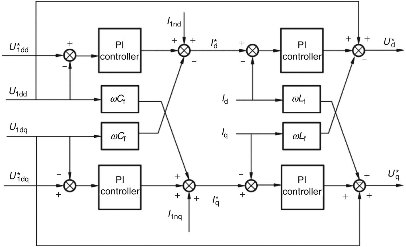
In this control mode, the AC-side voltage is regulated according to voltage feedback from the inverter to maintain a constant output, and the dualloop control scheme with outer-loop voltage control and inner-loop current control is often adopted. Outer-loop voltage control can maintain stable voltage output, and inner-loop current control constitutes the current servomechanism system, and can significantly accelerate the dynamic process to defend against disturbances. This dual-loop control can make the best use of system status information, and has a high dynamic performance and steady-state precision. Furthermore, inner-loop current control increases the bandwidth of the inverter control system, thereby speeding up the dynamic response of the inverter, enhancing the inverter’s adaptability to nonlinear load disturbance, and reducing harmonic distortion of the output voltage.
The U/f control is similar to P/Q control in terms of decoupling and control mechanism. Figure 2.8 shows the schematic diagram of U/f control, where outer-loop voltage control and inner-loop current control are adopted and the reference voltages Uldd * and Uldq * and measured voltages Uldd and Uldq are specified.
21 2.4 Control modes
■ FIGURE 2.8 Schematic diagram of U/f control.
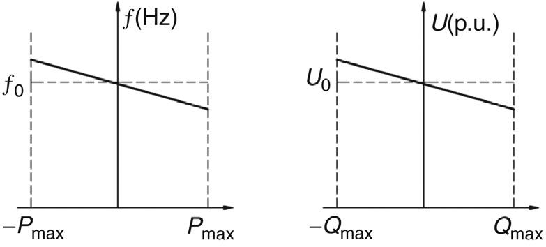
2.4.2.3 Droop control
Droop control is realized by simulating the droop characteristic of generators in a traditional grid and controlling the output voltage and frequency of the voltage source inverter (VSI) according to variation of the output power. The control strategy is based on inverter parallel-connection technology. As all DGs are integrated to the microgrid via inverters, the microgrid in islanded operation is equivalent to multiple inverters being connected in parallel, and the active and reactive output of individual inverters are, respectively
where U is the integration voltage, Un the output voltage of the inverter power supply, Xn the output impedance of the inverter power supply, and dn the included angle between Un and U.
According to Eq. (2.4), the delivery of active power mainly depends on dn and that of reactive power mainly depends on the output voltage amplitude of the inverter power supply Un. Un can be directly controlled, and the phase can be controlled by adjusting the output angular frequency or frequency of the inverter, as expressed in Eq. (2.5):
It can be seen from Eqs (2.4) and (2.5) that the output voltage of the inverter can be regulated by regulating its reactive output, and the output frequency can be regulated by regulating its active output. Figure 2.9 shows the droop control characteristic so derived.
Reverse droop control is to control the active and reactive outputs by measuring grid voltage amplitude and frequency to trace the predefined droop
■ FIGURE 2.9 Droop control characteristic.
22 CHAPTER 2 Composition and classification of the microgrid
P UU X Q UUU X n n n n n n n 2 =δ = (2.4)
f t 2 d d n nnω π == δ (2.5)
characteristic. This is a total reversion of the control mode where the output voltage is regulated by measuring the output power and therefore called reverse droop control. As the name implies, the reactive output and active output of the inverter are regulated by regulating the output voltage amplitude and output frequency, respectively.
To make the microgrid operational, inverters may adopt P/Q control, droop control or reverse droop control, and with these control modes, the output power of DG can be controlled by simply measuring local data.
2.5 INTEGR ATION VOLTAGE CLASS
Microgrids can be integrated into grids at the following three voltages:
1. 380 V (mains)
2. 10 kV
3. A hybrid of 380 V and 10 kV.
Figure 2.10 shows the integration voltages of a microgrid. Figure 2.10a represents integration to a 380 V (mains) LV distribution network, Figure 2.10b represents integration to a 10 kV distribution network with the voltage being increased to 10 kV from 380 V by a step-up transformer, and Figure 2.10c represents integration to a 380 V (mains) LV distribution network and a 10 kV distribution network.
2.6 CLASSIFICATION
Different types of microgrids should be established according to capacity, location, and types of DRs to suit the local situation. Microgrids can be classified as follows.
2.6.1
By function demand
Microgrids are classified into simple microgrid, multi-DG microgrid, and utility microgrid by function demand.
2.6.1.1
Simple microgrid
A simple microgrid contains only one type of DG, has simple functions and design, and is intended for use of CCHP or continuous supply to critical loads.
2.6.1.2
Multi-DG microgrid
A multi-DG microgrid is composed of multiple simple microgrids or multiple types of complementary, coordinated DGs. Compared with a simple microgrid, the design and operation of such a grid are much more
23 2.6 Classification

■ FIGURE 2.10 Microgrid integration voltage classes. (a) 380 V, (b) 10 kV, and (c) hybrid of 380 V and 10 kV.
complicated. Some loads need to be identified as sheddable loads in case of emergency to maintain power balance during islanded operation.
2.6.1.3 Utility microgrid
All DGs and microgrids that meet specific technical conditions can be integrated into a utility microgrid. In such a microgrid, loads are prioritized based on users’ requirements on reliability, and high-priority loads will be powered preferentially in an emergency.
Classifying microgrids by function demand clearly defines the ownership of a microgrid during operation: simple microgrids can be operated and managed by customers, utility microgrids can be operated by utilities, and multi-DG microgrids can be operated either by utilities or customers.
24 CHAPTER 2 Composition and classification of the microgrid
