Evolution of a E-fuels • Hydrogen • Additive manufacturing • Tyres • Natural fibres • Electric hybrid efficiency • Sensors Sustainable racing technology – the inside story NEW! 116PAGE SPECIAL EDITION >>> Target zero How motorsport is tackling its environmental impact 9 7 8 1 3 9 9 9 3 6 2 7 9 0 0 ISBN 978-1-3999-3627-9 £9.99 FROM THE EXPERTS AT
With a hydrogen combustion engine built for motorsport, AVL RACETECH is aiming to prove that it is possible to achieve high specific performance with this technology.


Maximum performance through water injection
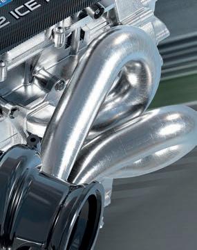
The 2-liter turbo AVL H2 race engine will generate approximately 300 kW - making it race fit for the production classes of today.
On the road to a green future in motorsport We are confident that hydrogen combustion will play an important role on the way to sustainable motorsport in the future.
www.avlracetech.com
AVL’s motorsport department is developing a new H2 combustion race engine CONTACT US: AVL RACETECH ON THE FRONT ROW OF H2 ICE TECHNOLOGY IN RACING
Email catherine.chapman@chelseamagazines.com
Email jodie.green@chelseamagazines.com Advertisement manager Lauren Mills Tel +44 (0) 20 7349 3796
Email lauren.mills@chelseamagazines.com
Subscriptions manager Luke Chadwick Tel +44 (0) 20 7349 3700
Email luke.chadwick@chelseamagazines.com
Editorial and advertising
Racecar Engineering Chelsea Magazine Company, Jubilee House, 2 Jubilee Place, London, SW3 3TQ Tel +44 (0) 20 7349 3700


Subscriptions Tel: +44 (0)1858 438443
Email: racecarengineering@subscription.co.uk Online: www.subscription.co.uk/chelsea/help
Post: Racecar Engineering, Subscriptions Department, Sovereign Park, Lathkill St, Market Harborough, Leicestershire LE16 9EF United Kingdom,
News distribution
Seymour International Ltd, 2 East Poultry Avenue, London EC1A 9PT
Tel +44 (0) 20 7429 4000 Fax +44 (0) 20 7429 4001 Email info@seymour.co.uk
Printed by William Gibbons
Printed in England
Evolution of a Racecar (print) ISBN 978-1-3999-3627-9
Evolution of a Racecar is a Racecar Engineering publication. Although due care has been taken to ensure that the content of this publication is accurate and up-to-date, the publisher can accept no liability for errors and omissions. Unless otherwise stated, this publication has not tested products or services that are described herein, and their inclusion does not imply any form of endorsement.
By accepting advertisements in this publication, the publisher does not warrant their accuracy, nor accept responsibility for their contents.
The publisher welcomes unsolicited manuscripts and illustrations but can accept no liability for their safe return. © 2022 Chelsea Magazine Company. All rights reserved. • Reproduction (in whole or in part) of any text, photograph or illustration contained in this publication without the written permission of the publisher is strictly prohibited. Evolution of a Racecar (ISBN 978-1-3999-3627-9) is published by Chelsea Magazine Company.
EVOLUTION OF A RACECAR | CONTENTS 3
Editor Andrew Cotton @RacecarEd Deputy editor Stewart Mitchell @RacecarEngineer Chief sub editor Mike Pye Art editor Barbara Stanley Technical consultant Peter Wright Contributors Dieter Rencken Lawrence Butcher Sam Smith Gemma Hatton Peter Wright Group sales director Catherine Chapman
Head of sales operations Jodie Green
Publisher Simon Temlett Managing director James Dobson Chairman Paul Dobson
66 74 48 59 22 14 Modern racing technology – the inside story Evolution of a POWERTRAIN 8 PERFORMANCE TARGETS New-for-2026 PU regulations ADVANCED MATERIALS 14 LUBRICATION Mobil 1’s oil for Honda F1 RENEWABLE FUELS 22 WINEBASED SOLUTION TotalEnergies’ 2022 WEC fuel ZERO EMISSIONS 30 HYDROGEN Development race underway ELECTRIC RACING 40 FORMULA E GEN 3 The series’ new all-electric racer RECYCLING 48 BATTERY APPLICATIONS A rapidly required market DOMESTIC HYBRID 59 BRITISH TOURING CARS The first of a new breed EFFICIENCY 66 ELECTRIC MOTORS A look at latest developments NATURAL MATERIALS 74 FIBRE COMPOSITES An alternative to carbon fibre WASTE REDUCTION 78 MOTORSPORT TYRES Finding sustainability in rubber NEW TECHNOLOGIES 88 ADDITIVE MANUFACTURING The world of 3D printing PERFORMANCE 96 SENSORS Finding performance in data ADVANCED FUELS 104 THE FUTURE FOR F1 A sustainable option? 110 THE OPTIONS AVAILABLE The arguments for...and against THE ASPHALT STORIES 114 LEENA GADE How OEMs should be using racing 30


VISIT www.chelseamagazines.com/CRCEER22 CALL US ON +44 (0)1858 438 443 and quote code CRCEER22 NB: *Free postage UK only. **Prices and discounts based on our annual UK rate of £84 / US rate of US$165.00 If for any reason you’re not happy with your subscription, you may cancel within 14 days of placing your order. Great savings when you subscribe Order your subscription TODAY The world’s leading motorsport technology magazine 12 issues from just £49.95 – SAVING 40% (UK delivery)* USD $109.95 / RoW £79.95 / AUD $159.95 / Europe €84.95* PLUS FREE access to the digital library of OVER 100 back issues! SAVE OVER £34 ** off the full price EXPERT ANALYSIS Updates from industry-leading engineers on and off the track TECHNOLOGY UPDATES Innovation and development for circuit and off-road series IN-DEPTH REPORTS News from major motorsport events, shows and conferences DETAILED REVIEWS Hardware and software for enhanced performance PROBING INTERVIEWS Key figures within the sport under our spotlight AERO STUDIES Behind-the-scenes insight from race series’ technical teams


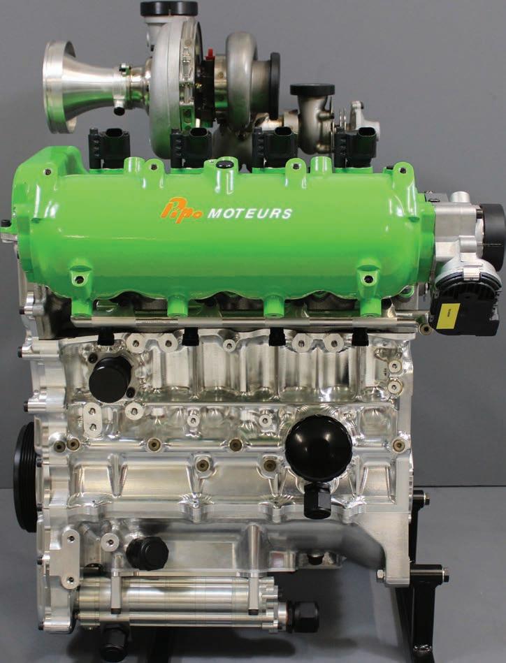

All ARP fasteners are manufactured entirely in our own facilities in Southern California and raced all over the world. Special Orders +1.805.525.1497 • Outside the U.S.A. +1.805.339.2200 1.800.826.3045 • arp-bolts.com 5,000 catalog items and specials by request TESTED & PROVEN Pipo Moteurs H2 hydrogen internal combustion engine utilizes custom and off-the-shelf ARP fasteners. ARP Fasteners are tested and proven in the most demanding environments on Earth...and beyond. Around. Above. Below.
All for one
How motorsport is helping to tackle the global energy and emissions crises
By Andrew Cotton
At time of writing, world leaders are gathering at the COP27 meeting in Egypt, looking to firm up commitments to reducing human impact on climate change.
Countries have different ways of reaching the same goal, but clearly there is a common will to reduce global emissions. The motor industry has taken something of centre stage in the process with bold ambitious targets being set by politicians that will have a dramatic impact on business and industry. By extension, motor racing has also found itself involved. In this edition, we look at the whole car concept, how different industries are working towards the same goal of making motoring cleaner, so it continues to remain viable.
There has been plenty of talk recently about racing, and why it should continue in this age of environmental awareness. However, looking at the impact of motor cars racing around a circuit, it is an insignificant amount compared to the travel to and from major events (and here I am including such occasions as soccer World Cups and the Olympics). Transport to and from any such meeting has high environmental cost and so organisers and suppliers are working to reduce these emissions through intelligent planning, as well as reducing emissions on the event itself.
It's not always easy. The Automobile Club de l’Ouest is looking to drastically cut overall carbon emissions from its flagship event, the 24 Hours of Le Mans, by reducing the number of cars allowed into the circuit during the event, decreasing traffic congestion around the circuit and neighbouring town and encouraging the use of public transport, which, if it works as it should, will be more convenient for the thousands of spectators.
The FIA is also looking at the overall impact of racing, and for example is awarding stars for circuits, companies and teams that have reduced their impact on the environment. Simple solutions can be effective here. At the Paul Ricard facility that hosts the French Grand Prix, as well as numerous other race events and private testing, cars are parked under canopies to protect them from the sun, while the canopies themselves are made up of solar panels. Clearly, there is plenty that can be done on a small level, while there is still an enormous amount of work that needs to happen on a more fundamental level. These are just small changes that need to be made, but there is a much bigger picture and racing can help.
In this edition, we look at more than just advances in fuel. While the politicians, particularly in Europe, focus on the way in which energy is produced to power the car and have zeroed in on electric, the entire process needs to be improved. From using alternatives to petrol and gasoline in an internal combustion engine car, be it electric or hydrogen, to reducing our demand on natural plants and earth resources, we have taken our lead from the racing teams and manufacturers to see what they are doing to improve efficiency.
We also look at how non-natural composite structures, such as carbon fibre, are being replaced with natural fibres by companies such as Bcomp, which is steadily increasing its reach within racing using flax fibres for seats, bodywork and aerodynamic devices.
The overriding sense that has come about from putting this special edition of Racecar Engineering together is that the most environmentally-friendly method, regardless of sphere, is to reduce production. More specifically, reduce waste. For that, we can take 3D printing as a prime example. In the process, material is added only where it is needed, rather than removed and summarily discarded. Structures can be made more complicated, lighter or more efficient, with better use of a wider range of materials.
Tyre companies talk of their interest in reducing waste, so producing fewer options for racing teams. They also talk about increasing efficiency across the board at the factories, how they extract what they can from their core product, and then how they responsibly dispose of the remnants of the tyre. They also look at transport costs and reducing the weight of transported goods.
We also focus on the increasing efficiency of hybrid and electric systems, from the motors themselves to the energy storage solutions. With politicians putting their faith in electric, hoping the technology will catch up with their ambition, it is fascinating to see the gains made by the companies actually producing the component parts, in particular by those involved in racing.
Of course, key to sustainability and keeping racing relevant is how to take the advances developed in these small number of prototypes and then scale up to production. Typically, racing teams are not equipped to do anything like that, and so rely on other companies to take their knowledge and escalate it into something meaningful. Here, we can take as an example synthetic and biofuels. Racing is currently demonstrating the amount of material needed to create the volumes required to meet its needs and it will be up to the big companies to extend this to production cars. We also need to ensure that what is used for fuel is not taken from another core requirement – feeding the increasing global population.
TotalEnergies believes it has the solution for the FIA World Endurance Championship, using waste product from wine-producing companies and turning that into fuel. But that is just one concept of many possibilities that will drive down the environmental impact of racing, and then by extension motoring. We consider each of the solutions, how they have evolved and where they might go in the future, to see how our industry can help the world remain on track to reduce global warming.
What's abundantly clear is that there is more to green technology than simply what fuel is put into the tank. The whole car concept is just as important, and racing is contributing a range of technical solutions that could be scaled up to reduce our impact on the planet.
We hope this special edition will fire the imagination and encourage further discussion of what needs to be done, and how racing teams, companies, manufacturers and sponsors can all help tackle the global crisis. l
Andrew Cotton is the editor of Racecar Engineering magazine
INTRODUCTION | ALTERNATIVE PROPULSION RACING 6
XPB
» The most environmentallyfriendly method, regardless of sphere, is to reduce production. More specifically, reduce waste

7
Formula 1 established a path to the future with its new engine regulations for 2026. There was a wide array of options available and negotiations were made more complicated by the different needs of the teams. Racecar spoke to key members of the paddock to understand the issue.
 By DIETER RENCKEN
Power politics

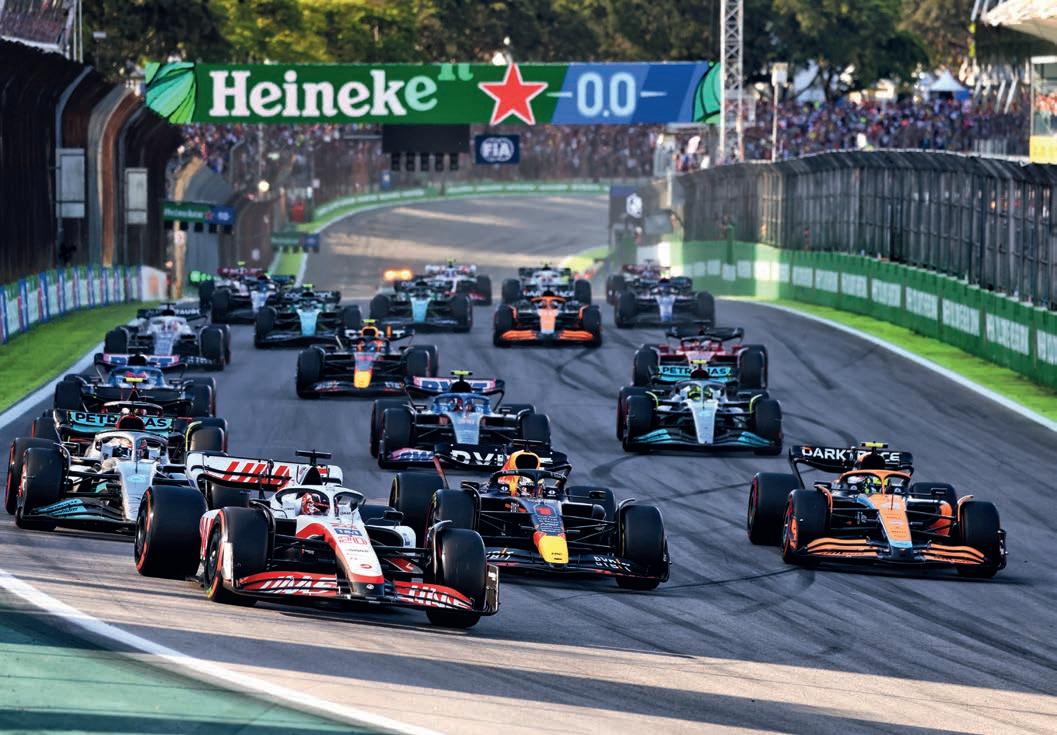
Formula 1 finally received the clarification it was looking for after months of negotiation. The newfor-2026 power unit regulations, announced in 2022, certainly point towards a more environmentally sustainable future for the sport. Under the new regulations, no new fossil fuel will be burned and carbon will be derived from non-food sources, genuine municipal waste and even from the atmosphere itself.
Hybrid energy, meanwhile, will provide three times the power compared to the current Formula 1 cars, pushing the maximum power available to more than 1000bhp. All of this, while using 30 per cent less fuel (from 100kg of fuel in 2020 to 70kg in 2026). That target is less than half the fuel used per grand prix in 2016.
The new regulations have gone further still, with lower costs thanks to identification of parts that can be upgraded during the lifecycle of the engine, and less testing. That means fewer hours on track, fewer hours on the dyno in testing, and yet innovation and competition will be as energetic as ever
Cars will also be safer, with the kinetic motor generator unit (MGU-K) to be housed within the chassis.
The number of power units will be limited during a season, placing emphasis on reliability, while less road-relevant technology, such as the MGU-H (harvesting energy from the exhaust gasses), have been dropped.
Finally, the new regulations will also regulate how teams deal with every aspect of their spent materials, encouraging them to recycle wherever possible.
This was certainly a fascinating set of rules, and probably the best of the options that were available. They have been enough to encourage in the new engine manufacturer that was desired from the Volkswagen Group, currently only Audi, although at the time of writing Porsche is still looking at joining its sister company in the competition.
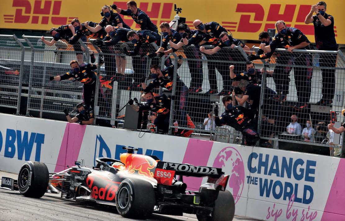
Honda, meanwhile, seems to be rowing back on its decision to end its involvement in
the sport, currently powering the Red Bull to its second World Championship title.


That has left the FIA and Formula 1 in a strong position. The two entities had to tread a thin line between what was realistic and what was popular. In this article we look at the options the two governing bodies had to consider during the negotiations.
Where once power units were restricted to internal combustion engines powered
FORMULA 1 | FUTURE POWER UNITS 8
by fossil fuels, and the only options apart from ignition – spark (petrol) or compression (diesel) – were reciprocating or rotary pistons, configuration and two or four strokes, the choices have multiplied exponentially.
Indeed, the FIA’s former secretary general for sport, Peter Bayer, ran out of fingers as he listed the number of potential options: fossil or synthetic-fuelled spark; compression or rotary internal combustion engines (ICE);
ditto with hybrid elements and / or powered by hydrogen or CNG (compressed natural gas); and purely electric motors, in turn energised by one of three variants, namely battery, hydrogen fuel cell or range-extended battery charged by any of the ICE types listed.

That potentially makes for 10 basic power unit alternatives, each with at least one suboption. It was, as Bayer freely admitted during the FIA’s annual member club conference
Formula 1 will retain its six-cylinder engines but they will be powered by sustainable fuel, will use half the fuel per race than in 2016, will have a higher electrical output than current engines and will run without the MGU-H that is too expensive and not relevant
in Monte Carlo in 2021, something of a power unit jungle out there, with none of the options providing a universal solution, whether for sporting, transportation or commuter applications.

Road relevance
The FIA, which holds global responsibility for both motorsport and mobility disciplines, elevated road relevance to the top of its agenda
9 XPB
» It became abundantly clear during the FIA conference that electricity is not the only alternative for future mobility, and that the internal combustion engine will be around for decades to come
and plans to formulate motorsport regulations that ultimately benefit global four-wheeled mobility, in all its forms.
The electric vehicle (EV) boxes are, of course, ticked by Formula E and various batterypowered tin-top series, while next year’s Dakar sees Audi enter its second generation range-extender concept, having already proven the technology in 2022.

That said, it became abundantly clear during the FIA conference that electricity is not the only alternative for future mobility, and that the internal combustion engine will be around for decades to come – regardless of what ecologists and politicians preach – if for no other reason than the world simply cannot generate sufficient affordable electricity and deliver it in sufficient quantities to charging points across the globe. In addition to this, Motorsport Industry Association (MIA) CEO, Chris Aylett, believes that, although consumers are being dictated to by governments to switch to electric, ‘too many nations can’t adapt, can’t afford it. Electric won’t work everywhere.
‘The internal combustion engine is still a very efficient mode of mobility and has been so for 100 years,’ Aylett adds. ‘There is plenty of potential there if we were not in such a hurry to go electric.
‘With regard to using sustainable fuels, I am quite sure we will go forward into the future with an urban electric solution, and a non-urban solution.’
There is another significant factor; 95 per cent of the global vehicle park is ICE-powered, and these cars cannot be scrapped overnight, something politicians – typically elected for five-year spells, and therefore with no need to play long games – conveniently overlook in their determination to shade themselves green. Crucially, 90 per cent of the 85 million cars that will be added to roads this year will be fuel-powered to some degree.
Disciples of electric vehicles predict enormous strides in battery technology over the next few years, often citing mass / power density advances that will reduce weight, cut costs and extend the range of EVs. However, they seldom acknowledge that such technologies apply equally to plug-in hybrid vehicles, and many deny that PHEVs could play a pivotal role in accelerating development of batteries, therefore serving hybrids and electric vehicles equally.
Yet both Renault and Alfa Romeo are currently committed to F1, despite corporate plans to go all-electric for their future product ranges, with the latter’s CEO, Jean-Phillipe Imparato, telling Racecar Engineering that spin offs from F1’s hybrid electrification provided the basis for the brand’s recent extension of its contract with Sauber.
‘The answer came naturally when I met [Sauber MD] Frederic Vasseur some months
before: to bet on Formula 1 as a next step in terms of technological content to fit my product, because Formula 1 is electrified since 2010. For me, in terms of rationale, it feeds the [brand’s] storytelling,’ he says. However, the entire auto industry, including F1, needs to dump fossil fuels and become carbon zero. Yet said public officials cannot even agree on the emission standards needed, let alone provide road maps for achieving it. Compounding the matter is the fact motorsport is not a political priority yet, rather ironically, could provide the technologies required for low or zero-carbon mobility solutions via synthetic fuels.
Poles apart
With F1 being both the most technological and visible of all FIA championships, it is the obvious series to pioneer sustainable fuels, and therefore this element lies at the heart of the sport’s plans for its future PU regulations.
Reaching such an agreement in Formula 1 was highly challenging given all the players have contrasting agendas. On the one hand Renault uses Formula 1 (largely) as a flagship for its range of mass produced econo-boxes, on the other Red Bull enters two teams to sell energy drinks via Formula 1’s popularity, yet aims to be totally self-sufficient.
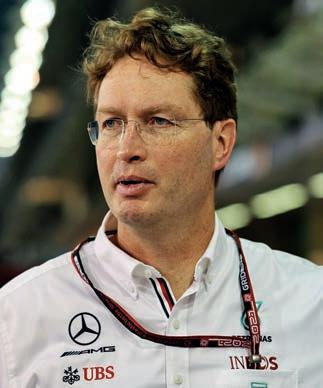
Sitting between these two extremes are Mercedes and Ferrari, premium automotive brands both with a determination to spend what it takes to prove their technical superiority to the world, particularly on the power unit front.
An example of the conflict reigning between the factions was aired by Red Bull’s Christian Horner and Mercedes motorsport boss, Toto Wolff, during the British Grand Prix weekend in 2021. Asked his preferences for future PUs, Horner said: ‘I think the combustion engine does have a future, so

FORMULA 1 | FUTURE POWER UNITS 10
why not introduce high revving engines
The FIA’s former secretary general, Peter Bayer, admitted there is a plethora of PU options
Audi will use a range extender on its RS Q e-Tron for the 2023 Dakar Rally, an alternative solution to pure electric mobility
» ‘I think the combustion engine does have a future, so why not introduce high revving engines that sound fantastic, and that do it in an environmentallyfriendly manner?’
XPB
Christian Horner, team principal at Red Bull Racing
that sound fantastic, and that do it in an environmentally-friendly manner?
‘I think biofuels and sustainable fuels enable you to do that. F1 could play a key role with the fuels and with the fuel partners we have on sustainability and zero emissions, with a high performance, high revving, emotive engine. I think every grand prix will be packed.’
Wolff, though, immediately disagreed ‘because it’s what we [the older generation] think, but we are not the most relevant generation. When you ask an 18-year old or 22-year old what relevance noise has, most of them consume [F1] via different screens where noise has little or no relevance.
‘I personally like it too, and I would like to have a 12-cylinder that screams down the road,’ Wolff continued, ‘but we are a sport and we are also a business. I think we would lose complete relevance with our partners, sponsors and major stakeholders if we weren’t looking at the environment and the impact that we make.’
See the conflict? One represents an edgy energy drink, the other a premium auto brand. Between them they have dominated the sport since 2010.
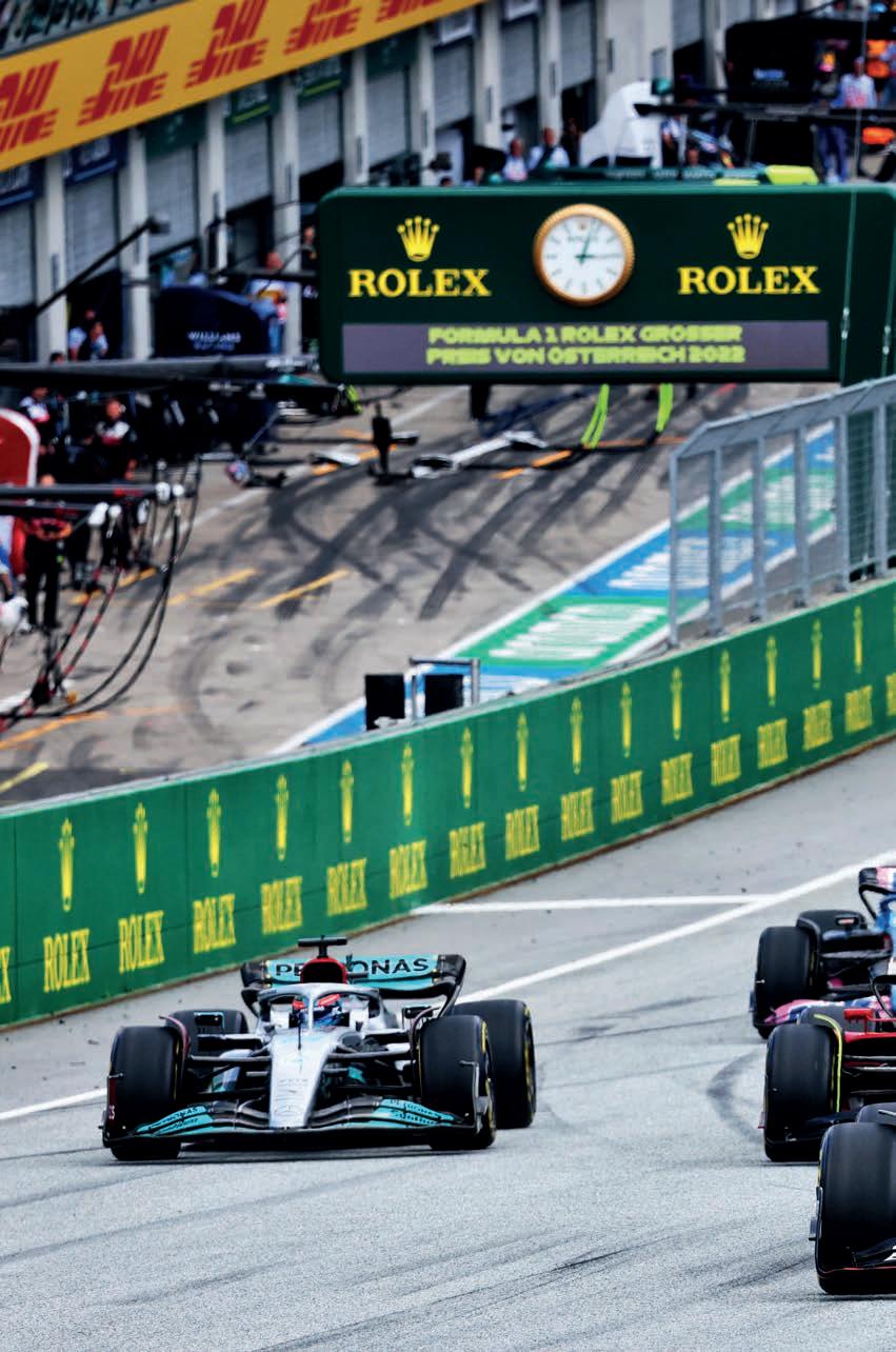
To set the ball rolling in order to reach agreement for the F1 regulations, the FIA and Formula 1 convened an engine summit during the Austrian Grand Prix weekend in 2021. In addition to F1 and FIA executives and senior officials, only CEOs of currently committed and potential engine suppliers were present at the meeting, held in the nearby five-star Hotel Steirerschlössl, owned by Red Bull proprietor, Dietrich Mateschitz.
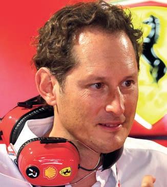
The invitation list – Ferrari president, John Elkann; Mercedes / Renault CEOs, Ola Kallenius and Luca de Meo; Horner representing Mateschitz, plus Porsche / Audi CEOs, Oliver Blume and Markus Duesmann –suggested the purpose was to formulate a top-down strategy and determine what the current suppliers are prepared to invest.
This approach differed from what went before when ambitious engineers, most with little grasp of marketing or economics, trotted out wish lists they submitted to the governing body. These were combined into a set of regulations that delivered the most complex (but admittedly efficient) engines in automotive history, though at eye-watering cost, said to average close to $2m per unit when measured across a season.
The summit agreed the new engines should deliver similar power levels to current units, so 1000bhp overall, but at lower cost (annual budgets of $100m, so around $30m per supplied team, as opposed to three times that). They must also run on zero-carbon fuels and provide substantially increased hybridisation (potentially a 50 / 50 split).
This pretty much sums up the regulations that were approved, and now the engineers ‘just’ have to make it happen.

At that meeting, various options were discussed in broad terms, including a switch from V6 to downsized four-cylinder inline units, as per road car trends, and scrapping the horrifically complex and expensive MGU-H units, which sap engine noise. The former was rejected on the grounds of cost, the latter accepted for the same reason.
‘The discussion was what are we doing in the future in terms of engine, because we want to save costs, so we don’t want to reinvent the wheel,’ Wolff (who did not attend the Austrian summit as he is not a director of Mercedes High Performance Powertrains), told the FIA conference.
‘We also want to have an engine that is relevant from 2025 to 2030, and we can’t be old petrolheads with screaming engines when everybody expects us to be going electric. So these engines are still going to be fuelled [by zero-carbon fuels]. We are staying with the current V6 format, but the electric component is going to massively increase,’ Wolff added, clearly pushing the Mercedes corporate line.
Power switch
FIA president, Jean Todt, retired at the end of 2021, handing over to his successor, Mohammed Ben Sulayem. Ben Sulayem now needs to implement the new set of regulations, maintain harmony among the competing teams and manufacturers, while, at the same time, keep a close eye on the selfimposed cost cap that will protect the teams at the back of the grid.
11
Toto Wolff and Christian Horner found themselves in disagreement over the direction Formula 1 should take with its new PUs
Ferrari boss, John Elkann, attended the 2021 Austrian engine summit with his own priorities
Ola Kallenius represented Mercedes at the PU summit
XPB
» Various options were discussed in broad terms, including a switch from V6 to downsized four-cylinder inline units, as per road car trends, and scrapping the horrifically complex and expensive MGU-H units
XPB
XPB
That Formula 1 needs to change its ways is clear. That the ICE is far from dead, equally so. The trick facing the FIA, Formula 1 and all engine suppliers, both present and potential, then, is to manage the switch in such a way that the final direction finds lasting favour amongst fans, sponsors, promoters and broadcasters, who will base their medium to long-term decisions upon a sustainable, biofuelled, hybrid engine formula.
The ultimate irony, though, is that after years of criticism of the current engine formula, 2022 delivered the best racing for many a year in Formula 1, yet its demise is now being widely debated due to external factors, a number of which are outside the sport’s direct control. l
The powers that be
There are already quite a few alternative energy solutions at play in the wider motorsport world, including of course Formula E. Scepticism abounded when in 2011 the FIA conceived the series, its first alternative energy championship. Yet it has gone from strength to strength, this year holding world championship status and boasting seven manufacturers – three more than Formula 1, although Audi, BMW and Mercedes have all now cancelled their FE programmes. There’s even Extreme E, a rally series for electric vehicles.
Meanwhile, F1’s support series, Porsche Supercup, and the European Truck Racing Championship have switched to petrol and diesel biofuels respectively, with Porsche reporting the former required only software updates to co-optimise engine and fuel performance, with output of the GT3 remaining unaffected.
The 2022 World Rally Championship went a step further by integrating biofuels and hybridisation, while WRX’s switch to full electric was delayed by the Covid pandemic.
In 2022, Audi debuted its RS Q e-Tron on the Dakar Rally using a 600bhp, ex-DTM ICE to power an FE-derived motor generator, which in turn charges 52kWh batteries that power two 335bhp FE electric motors. In this configuration,
the car can now complete stages without regular charging, although the plan is for overnight charging via auxiliary generators.
Range extenders could also see use at Le Mans, with a project combining a Mazda rotary engine running at constant speed to charge batteries rumoured as a Garage 56 entry.
However, ACO president, Pierre Fillon, whose club promotes the 24-hour race, believes ‘Hydrogen is one of the best energies for future mobility, and will play a key role in Le Mans in 10 years. We will have zero CO2 emissions, with hydrogen as the top class and e-fuels in the lower classes, and we will stage an exemplary event in terms of social responsibility.’
In May, Toyota chairman, Akio Toyoda, completed the 24 Hours of Fuji in a Corolla powered by a turbocharged, inline, threecylinder engine fuelled by compressed hydrogen, an exercise Bayer labels as ‘super interesting, something we are analysing and studying’.
‘The goal is to be carbon neutral,’ Toyoda said. ‘If all cars become battery electric, one million jobs will be lost in Japan. I want to tell the world there is also this option to become carbon neutral.’
Motorsport now merely needs to introduce a series for hydrogen fuel cell technologies to cover the full spectrum of alternative energies…
FORMULA 1 | FUTURE POWER UNITS 12
»
‘We are staying with the current V6 format, but the electric component is going to massively increase’
Toto Wolff, team principal and CEO at Mercedes
The trick now for Formula 1 is to lead the way in technological development, while at the same time keeping fans, sponsors, promoters and broadcasters happy. No mean feat
XPB
High-end drivetrain technology Made in Germany


Made in ack ted entials tree t an an code al offer.
Be on the fast track with our custommade limited slip differentials and other drivetrain parts for street an racecars. Scan the QR code to get your personal offer.
tr custommade limi differ par ts for s racecars . Sc person
PERFORMANCE makes the difference Drexler Automotive GmbH Postgasse 12 c, d D-94121 Salzweg T +49 851 851 6363 0 mail@drexler-automotive.com drexler-automotive.com
dif ference
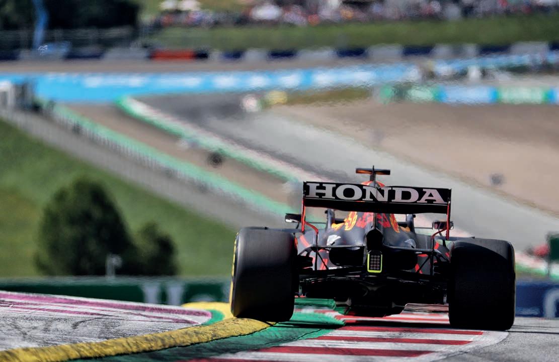
Blended learning
Racecar investigates how Mobil 1’s engine oil is offering a performance advantage for Honda-powered Formula 1 teams
 By Stewart Mitchell
FORMULA 1 | LUBRICANTS 14
© Htpix14 | Dreamstime.com
Few mechanical systems put as much stress on their components as a Formula1 hybrid power unit. Providing technical solutions in such a demanding environment pushes suppliers to enhance their products and develop new technologies in a bid to yield an advantage over rivals on the track.
The partnership between Honda and the Red Bull Technology group Formula1 teams, Red Bull Racing and Alpha Tauri, has provided a key learning platform and a proving ground for the fuels and lubricants brand, Mobil 1.

The partnership provides Mobil1 with the opportunity to improve its engine fluid technologies, raising the standard of lubricant and fuel performance for its customers, while at the same time delivering higher resilience to contamination and longer service intervals.
Mobil 1 and Honda’s engineers have worked closely with Red Bull Technology since changing from a power unit supplier to a partnership with Toro Rosso in 2018.
‘That shift in the relationship has made a significant difference,’ highlights Honda F1 technical director, Toyoharu Tanabe.
15
» ‘I think the results will bring advantages both to the racing world in Formula 1… and in the consumer car world and with road car engines in general’
Tomek Young, global motorsport technology manager at Mobil 1
Photos: XPB
‘We had many meetings to develop our relationship, which is not only technical but also personal. We have very open communication between Mobil 1 engineers and Honda engineers.
‘Reviewing the test data, we initially looked at the direction for development and a new lubrication solution for the 2021 Honda power unit, and this provided us with higher performance for the Red Bull Racing and Scuderia Alpha Tauri Formula 1 teams.’

Blend development
Mobil 1’s lubricant formulation for the Hondapowered Red Bull Technology group F1 teams was led by Tomek Young, Mobil 1’s global motorsport technology manager.
‘The engine oil interacts with many parts, and we’re careful when changing its chemistry,’ highlights Young. ‘When we have a proven formula, moving to a new generation poses potential risks. Before we change anything, we must be confident that the performance gains are worth the risk of potential reliability issues, which carry a heavy penalty.’
Mobil 1 begin with computer modelling and simulating the lubrication regime in the digital world. Once the company is confident with the oil’s performance in simulation, it tests it in a laboratory environment before moving to single-cylinder test rigs with some small batches of the new blend. Following that, the formulation is further refined where needed and goes on to Honda for its engineers to put in their complete power unit test stands. Only after passing all these tests does it go into the racecar.
‘We use much more fuel with Honda off track than we use on the track,’ explains Young of the process. ‘We have done a lot of testing to push the boundaries of what’s possible with the race engine oil and have a unique molecular composition of products for this Honda Formula 1 power unit engine oil not seen anywhere else.
‘There are traditional elements used in race engine oil such as those that offer anti-wear properties, including boron, zinc, phosphorus and sulphur. Some base stocks are also traditional.
‘We asked the question: can we change the composition completely? We started to look in some unusual places for components and compounds that would improve the oil in a Formula 1 application and make it even more effective. We searched for the characteristics we wanted in many different applications, including the cosmetics industry, and we brought in some new components to our race oil formulation.

‘Specifically, we were able to eliminate some of the metals that were previously used, and we’ve been able to limit the content of others, making this oil stand out in sustainability as well as performance.’
The Mobil 1 oil poured into the Hondapowered Formula 1 teams’ cars at the Baku round in 2021 brought together many years of work on multiple iterations, as Young explains: ‘That blend culminated eight years of lubrication research and development.
It gave the Honda-powered race teams a performance advantage on track, and helped us improve our product for our commercial customers, too.’
Performance act
That’s all well and good coming from the supplier, but how do you quantify a performance advantage from a lubricant? The primary driver for oil in the Formula 1 engine environment is the power unit’s performance, and to maximise that is to minimise friction losses. Internal combustion engines are energy conversion devices –they convert chemical energy in the fuel at the injectors into mechanical energy at the engine output shaft.
A significant percentage of the chemical energy delivered to the combustion chamber is lost to mechanical friction between components, the most significant of which are the piston and cylinder interface, and the con rod and big end bearing assemblies.
Developing an oil to provide a higherperforming lubrication regime with less friction in these areas offers a considerable contribution to engine performance.
Reducing friction also has a knock-on effect in other areas of engine efficiency, such as lessening the amount of energy required to carry out the non-firing strokes, known as pumping losses.
Additionally, wear on the engine is reduced, giving it the ability to run at a higher-performing mode for more miles.
FORMULA 1 | LUBRICANTS 16
»
‘Our relationship… is not only technical but also personal. We have very open communication between Mobil 1 engineers and Honda engineers’
Toyoharu Tanabe, technical director at Honda F1
Paul Monaghan, Red Bull Racing Honda chief engineer of car engineering
Honda F1 technical director, Toyoharu Tanabe
Since Technical Directive 37 was introduced at the Monza, Italy round of the 2020 championship, restricting the number of engine modes teams can use, the ability to change into different performance modes to manage energy and race strategy is gone. As such, teams want to run in the most performant mode for the entire weekend, provided the powertrain can handle it. Reliability is therefore key, and can be aided by a higher-performing oil, making it easier for teams to observe the three power units per year regulation.
‘Friction reduction improves the engine considerably,’ says Young. ‘Efficiency improvements form an effective route to enhance our challenge for this season’s championship, and forthcoming seasons championship battles.’

Thermal conductivity
The ability to carry heat is one of the critical functions of engine oil, and that function is one that Mobil 1 has been investigating in great detail with Honda and carefully optimising for the Formula 1 application.
‘We try to maximise the heat capacity per molecule of the lubricant,’ notes Young. ‘However, the oil must not only have heat capacity, but also a high thermal conductivity, releasing the heat as it passes through the heat exchanging device quickly and efficiently. Improving the conductivity of the oil is an effective route to lowering the running temperature of the engine.’
The 2021 engine oil was able to withstand significantly higher temperatures than its predecessor, and that has potentially huge knock-on effects for the design of other components on the car. For example, the Honda-powered cars now have scope to design a smaller, more efficient engine and consequently improve the car’s aerodynamics, the most performancedependent factor in current Formula 1.
‘We’re not yet taking full advantage of that ability, but we have done some work,’ notes Paul Monaghan, Red Bull Racing Honda chief engineer of car engineering. ‘Mobil 1 made the oil performance so high that we could potentially run the power unit even harder down the road, and much more optimisation of the power unit, aerodynamics and car operation will be possible.
‘When we do optimise the car, we will know how much of a difference the oil can make, and we are confident it can make a tangible difference in terms of the overall performance of the car, primarily in the cooling configuration.
‘The new oil may affect the decisions made for the next year’s car. For now though, it is fair to say these are early days in terms of establishing just how high we could push the oil on the car.
17
Since the introduction of Technical Directive 37, teams want to be able to run at the highest performance mode possible at all times
‘The limits are dependent not only on the oil’s ability to take heat out of the engine and exchange it through a cooler but, thanks to the work Mobil 1 has done with the oil’s ability to withstand high temperatures, we can also keep the turbo running temperatures down to a level where Honda can design an engine that has effectively moved the temperature targets without consequence. Having said that, we could also lift the operating temperature of the engine, but that does not mean it’s going to run as we would want. We have a range of cooling solutions on the car with bodywork to test using different inlet and exit configurations.
‘With the new oil, we can tune the engine not only for an operating condition but push whatever Mobil 1 and Honda allow us to run.
‘We can also split the cooling system to treat cooling circuits independently, allowing for more tuneability. Sometimes, they might ask for a bit more cooling, or less. If they want a little bit less, we will be able to close the bodywork up a bit and run the car generally hotter but with more aerodynamic efficiency.
‘It is impossible to treat a set of operating parameters and car set-up in isolation as one, typically, will influence in the other. Whether we can take greater steps through this season, we do not know just yet. We are on the learning curve right now, and the more we learn, the more we will exploit it.
‘Even now, it’s still early stages so it’s not a considerable effect on the car performance yet. Whether it becomes that is very much down to cleverer people than I.

‘The new oil formulation enables huge potential and a steep development curve. The next iteration of the Red Bull Technology group cars could be quite a big step up in performance once we have built up more real-world experience with the new oil.’
Fighting LSPI
Even in the most efficient performance operating regions of the latest Formula 1 engines, the most efficient race power units on the planet, not all the fuel injected into the combustion chamber burns to generate power thanks to crevice losses around the spark plug, valve seats and piston top land. Formula 1 engines typically have very low crevice volumes, but still roughly two per cent of the injected fuel escapes combustion by residing in them.
From a mass standpoint, the most significant single crevice is the area around the top piston ring land. If exacerbated by high cylinder pressures (high charge density), combustion can occur in that region. It has been discovered that even a minuscule amount of engine oil that enters the combustion chamber can affect this
Improving the oil’s heat capacity and thermal conductivity has knock-on effects on many other areas of the racecar, including cooling, packaging, bodywork and, ultimately, aerodynamics, too
type of combustion and the performance of the engine in a dramatic way.
A phenomenon called low-speed pre-ignition (LSPI) can be catastrophic, potentially even destroying the engine, and it is particularly bad in small displacement, turbocharged, direct-injection engines.
While the fuel that goes in the tank is a liquid, the engine must convert that liquid into a vapour to burn it. If the fuel does not turn into a vapour, the engine cannot burn it.
FORMULA 1 | LUBRICANTS 18
»
‘Thanks to the work Mobil 1 has done with the oil’s ability to withstand high temperatures… Honda can do an engine that has effectively moved the temperature targets without consequence’
Paul Monaghan, chief engineer of car engineering at Red Bull Racing Honda
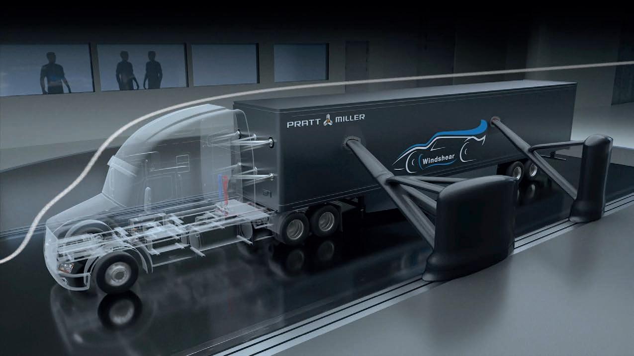
Take cutting-edge wind tunnel technology.Add a 180 mph rolling road. And build in the best in precision data acquisition capabilities.When we created the world’s first and finest commercially available full-scale testing environment of its kind, we did much more than create a new wind tunnel. We created a new standard in aerodynamics.
180 MPH WITHOUT MOVING AN INCH 704-788-9463INFO@WINDSHEARINC.COM
WSI-28 WSI-28_Motorsports.vF.indd 1 8/15/08 11:08:14 AM
704-788-9463 INFO@WINDSHEARINC.COM WINDSHEARINC.COM
Take cutting-edge wind tunnel technology. Add a 180 mph rolling road. And build in the best in precision data acquisition capabilities. When we created the world’s first and finest commercially available full-scale testing environment of its kind, we did much more than create a new wind tunnel. We created a new standard in aerodynamics. WINDSHEARINC.COM WSI-28
Because direct-injection engines spray the fuel directly into the combustion chambers, some unburnt fuel mixes with the oil that lubricates the cylinder walls. This mixing of liquid fuel and oil is where things begin to go bad, chemically speaking.
Engine oil is a mixture of base oil and additives. The additives used in the oil influence how well the oil and fuel will (or will not) mix. If fuel in the top ring land crevice and oil mix, it creates a volatile mixture that can lead to LSPI - a combustion event prior to the spark event. This causes abnormally high pressures within the cylinders, which can potentially damage pistons.
Engine lubricant research indicates the engine oil formula directly links to the frequency and severity of LSPI.
Said research has found that reducing the amount of calcium detergent and eliminating sodium detergent in the oil reduces the frequency and severity of LSPI and other abnormal combustion events caused by mixing of the oil and fuel.
Calcium-based detergents are widely used in off-the-shelf engine oils, typically in high concentrations. Mobil 1’s Formula 1 engine oil reduces these and is explicitly formulated for direct-injection engines, designed to avoid potentially catastrophic LSPI events, and ensure long-term engine durability.
‘We’ve been playing with the concentrations of various constituents to reduce the risk of LSPI and notice that as we

Recent developments haven’t just been about performance. By eliminating some of the metals used and increasing its biobased content, Mobil 1’s oil is now also more environmentally friendly
change some of these oil elements, it can affect regular combustion in some ways as well,’ explains Young.
‘So, even though the oil is not viewed as part of the combustion process, it actually is, and this is just one example of areas we explored. I think the results will bring advantages both to the racing world in Formula 1 with the Red Bull Technology group teams, and in the consumer car world with road car engines in general.’
Bio-based content
In terms of the sustainability of Mobil 1’s engine lubricant products, when the technology is moved out of the Formula 1 environment into the road car environment, there is strict legislation in place for emissions.
‘When we talk specifically about oil consumption, it is a minuscule number of particles entering the combustion chamber, so you would not even see the oil level decreasing over a regular drain interval,’ explains Young. ‘The lubricants industry is governed by environmental legislation in countries and regions, but mostly it is limited by regulations that engine manufacturers and the automotive sector imposes on itself. Specifically, several tests are carried out that measure the volatility and emissions of oil in the combustion chamber that oil manufacturers must pass, proving that the oil does not negatively affect combustion.
‘To improve the sustainability of our lubricant products, we have adjusted the chemistry of our base stocks. The base stocks are the largest percentage of an engine oil, and we challenged ourselves to see if we can use something that is environmentally friendlier at the pinnacle of motorsports.
‘We use base stock with a high percentage of bio-based content. It is over 25 per cent now in the oil used in the Honda-powered Formula 1 cars on track. It is not often thought that environmental formulations coincide with high performance, but it does. In fact, in the case of the engine oil that Mobil 1 developed for the Hondapowered Formula 1 teams on the grid in 2021, it enhanced it. The use of bio-based components helps Honda-powered teams win races, which is tremendous for us. We are so excited about its influence and potential for Honda power going forward.’ l
FORMULA 1 | LUBRICANTS 20
»
‘It is not often thought that environmental formulations coincide with high performance, but it does’
Tomek Young, global motorsport technology manager at Mobil 1


www.racecar-engineering.com 21 The Winners Racing Cooler print.pdf 1 09/05/2022 16:58 The evolution of metalworking fluid Total Folia The green revolution in metalworking: • Mineral oil free formulation •Transparent product good visibility •Low foaming with demineralised water •Very low odour •No fume emission •No tramp oil retention •Long sump life •Aluminium, heavy duty and cobalt leeching varieties currently available •Call us to discuss your Total Folia requirements +44(0)1530 833899 sales@lubrication.net www.lubrication.net lubrication Metalworking Specialists Lubrication-Racecar-Half-Page-Nov-2022.qxp_Layout 1 15/11/2022 11:03 Page 1
WEC | RENEWABLE FUEL 22
» A 100 per cent renewable fuel that will reduce CO2 emissions by at least 65 per cent
Waste management
TotalEnergies introduced a new fuel to the World Endurance Championship and European Le Mans Series in 2022. Racecar investigates
By Andrew Cotton and Stewart Mitchell
To remove the risk of any potential discrepancies, TotalEnergies has produced 1000m3, around a million litres, of Excellium Racing 100, enough to service the WEC, ELMS and support races for the period of its agreed three-year association with the series

23
WEC | RENEWABLE FUEL 24
» A hydrocarbon-based fuel from ethanol produced in the process of fermenting wine
The traditional Friday press conference at Le Mans in 2021 heralded the announcement that the series fuel partner, TotalEnergies, would supply 100 per cent renewable fuel that reduces CO2 emissions by at least 65 per cent for the 2022 FIA World Endurance Championship.
This was quite some claim, one that potentially would have a huge impact on the engine development teams in each of the classes as previous renewable fuels have different properties compared to traditional oil-based petrol.
Not so, says TotalEnergies. It has worked to produce a fuel that mimics the petroleum competition fuel used in 2021. Since its introduction there have been some issues with the engines, but overall it has been a positive step forward for the series.
With more than 60 cars on the grid at Le Mans featuring a combination of turbocharged and normally-aspirated engines, there was always a risk the new fuel would suit some layouts and sizes better than others. Teams were given as much notice as possible regarding the change, and TotalEnergies supplied samples for testing before the end of the year. That was still a tight timeframe as normally fuel would be tested for a year in advance, but the FIA and ACO were determined to push their green credentials.
TotalEnergies’ fuel is made of a hydrocarbon-based fuel from ethanol produced in the process of fermenting wine, a popular activity in France. Although the French are well known for their wine making, the fuel could be made from other traditional alcohols such as whiskey and vodka, and from all kinds of crops, including wheat and corn. In fact, any process that creates ethanol would be suitable for making the base needed to produce fuel, says the company.
Crop-to-wheel
As such, the emission from the exhaust pipe is not where the quoted CO2 savings come from. TotalEnergies has neatly side stepped the ethanol production process by taking what would otherwise be wasted material, fit either to be burned or disposed of, and creating the fuel from that waste product.
The reduction in CO2 emissions is therefore from crop-to-wheel, compared to well-to-wheel in production of petrol, but nevertheless is a product the manufacturers involved in endurance racing have been looking for in order to extend the life of the internal combustion engine in a racing application.
There is nothing new in the production of ethanol and its use in fuels. A percentage
25
With such a variety of racecars in the WEC, there was some concern the new fuel would suit some better than others, but that didn’t happen
of all fuel put into your everyday car includes an amount of ethanol, E5, E10 or E20 denoting the percentage of it in the finished product. However, the ethanol content does not have the same high calorific value as traditional fuel, and so fuel consumption is higher, although the higher octane level increases power and performance.
Volume control
The timing of the announcement took many by surprise, and there was good reason to keep it quiet because TotalEnergies was not certain it could produce the volume of fuel required to service the championship and its supporting races for the entire 2022 season.
Although the FIA and ACO have been looking at alternatives to oil-based fuels, they had previously denied making any final decision and were pinning their hopes on hydrogen, which is scheduled to have its own class in 2025.
However, a decision had been taken to produce a new fuel that would reduce the CO2 footprint and continue the sustainability drive the ACO and FIA is looking to achieve.
‘Even though we started the technical discussion with the manufacturers on the fuel formulation and the impact on the engines, we wanted to be sure we had the volume for the 2022 season,’ said Romain Aubry, TotalEnergies’ multi-energy technical manager, who was project leader on the development of the renewable racing fuel. ‘The decision came early in summer [2021]. If Le Mans was mid-June [as originally scheduled] we may have been short of time.’
Prior to Le Mans, the company had already conducted single-cylinder testing on its own test benches and created a fuel that had minimal impact on engine performance, not only in terms of power but also burn temperatures and consumption. This was critical to the championship that consists of engines from Gibson that have been supplied to LMP2 since 2017, as well as newer engines in the top Prototype class from Gibson, Pipo Moteurs and Toyota. Not to mention the GT contenders.
‘On a mono-cylinder [engine] we tried different formulations with a renewable fuel and we wanted the impact to be very small compared to [our existing] fuel, because
the formulation uses hydrocarbons,’ says Aubry. ‘That means our raw material is ethanol, and then we use a process called ETG, so ethanol to gasoline. We transform the compound into a real hydrocarbon.
‘The fuel is pretty much the same as that made from oil, except all the fuel is renewable. The fuel generally is composed of paraffin, olefin aromatic and oxygenate compound and you will find all these compounds in this new fuel.’
WEC | RENEWABLE FUEL 26
»
‘I think this kind of fuel was what the manufacturers want in terms of corporate communication to move from oil origin fuel to a renewable one’
Romain Aubry, multi-energy technical manager at TotalEnergies
At 40MJ/kg, the calorific content of the new fuel is the same as that of traditional oil-based fuels and only minor changes were needed to address performance balancing issues
The process takes the ethanol that is created from the fermentation process of the wine lees or grape pomace, after which it is dehydrated, and then the ethanol compound is evolved into hydrocarbons through a blend with Ethyl Tertio Butyl Ether (ETBE), itself a by-product made from ethanol. It is then combined with several performance additives issued from the Excellium technology developed by TotalEnergies.
Although it would be possible to transport the dehydrated core material to make the fuel elsewhere, there is little point in doing so as it is the gas created throughout the process that is the key element, so it makes sense to complete the process in one go.
Quality control


TotalEnergies needed to be sure the batch was all the same quality and so produced 1000m3 of fuel, around a million litres, all at the same time in order to service the WEC, ELMS and the various support races. That figure comes after a three-year association with the series in which precise amounts required for testing and race conditions were already confirmed.


Technology step


This is not the first time endurance racing has experimented with plant-based fuels. As long ago as 2003, the British Nasamax team took to the track at Le Mans with a bio ethanol-fuelled Reynard. Since then, the fuel has gone through several iterations, notably in the ALMS, where first and second-generation waste was used in its production. However, these were oxygenated fuels, which meant they did not have the calorific value of fossil-based fuels. What also became apparent was that produce that could have been used for human or animal consumption was instead being grown to provide fuel.


‘We are putting into competition biofuel rather than food,’ says Aubry. ‘All our raw material is waste, and cannot be used by animal or human feeding. It should have been burned or not used. That was one of the first decisions, to ensure we were not using first generation [material] and that was something that was needed.


‘The first generation of bio fuel was made with oxygenated content. Using oxygenated methanol, ethanol will always reduce calorific value, and that will increase fuel consumption to make the same energy from the engine. The technology step [we have made] is to produce real hydrocarbons from waste, meaning we maintain the calorific value, the octane and so maintain the fuel consumption of a standard fuel today. This was to show that we still can work with standard hydrocarbons, but made from renewable materials.’

Aubry, multi-


Producing the full amount of fuel required in one batch means the product is predictable in its properties and there is a reduced possibility of discrepancies.


The fuel was be introduced on track before the end of 2021 in order for evaluation to take place by both TotalEnergies and the race organisers to see what changes, if any, need to be made to the Balance of Performance for each class. The BoP did, indeed change for the 2022 season, with slightly more fuel permitted per stint, and the engine maps were also altered slightly compared to 2021.


Calorific value
By retaining the hydrocarbon element, the team was able to maintain the same calorific value as traditional fuels which reduced the amount of changes needed for the performance balancing.
‘We are at 40MJ per kg, so that is the same as a standard fuel,’ says Aubry. ‘The octane level is above 100, though, so we are really comparable to a racing fuel. If you do all the different chemical and physical tests on the fuel, you won’t see any difference. The only difference is the adaptation from carbon 14.
‘If we look on the combustion process, it has remained the same. The 65 per cent reduction [in CO2] is made on the complete life cycle of the fuel, so not just combustion from well-to-wheel. This is from crops-towheel. We based all the calculations on European legislation RED, which is Renewable Energy Directive taken from the European commission, so we ensured that we used something known in the field. It is not our calculation, it is well known by the profession.’
Even though there was an opportunity during the development process to tune the fuel differently, either to provide better efficiency or more power, that was not the point of its introduction. Improvements in the chemical properties of the fuel for power or consumption figures will come further down the line.
‘This introduction of Excellium Racing 100 was the first step for the championship to reduce its CO2 emission,’ confirms Aubry. ‘We wanted to bring consistency through the season. We don’t want to change the fuel in two or three seasons, we want to see how the technology from our process will evolve,
27
» ‘All our raw material is waste, and cannot be used by animal or human feeding’
Romain
energy technical manager at TotalEnergies
and the engines, to see if we can have a second step in four or five seasons.
‘I think this kind of fuel was what the manufacturers want in terms of corporate communication to move from oil origin fuel to a renewable one. We are still all learning [about it] and then one of the steps after will be to reduce fuel consumption again.’
Learning process
The process started when the company was involved in Formula 1, and it continued when it took over from Shell as the sole supplier to the WEC in 2018. ‘We are still learning about fuel but, if we can improve the efficiency of thermic engines, we need to do it,’ says Aubry, keen to emphasise this is only the first stage of the process to improve the carbon efficiency of the ACO’s endurance racing series.
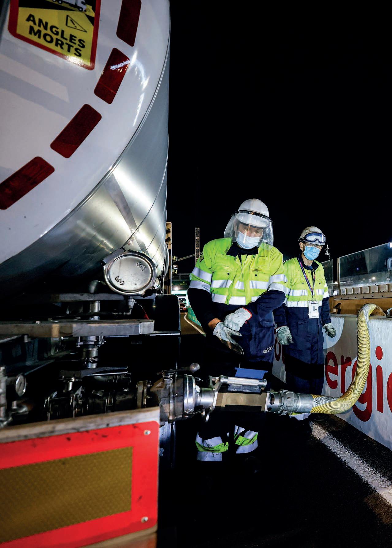
The next stage is to close the loop by providing the factory that produces the fuel with renewable fuels, followed by the extension of uses for the fuel into other areas in the paddock, such as powering the trucks that transport the cars to and from tracks. This transport cost to the environment, coupled with the carbon emissions of spectators attending the event, are higher than the cars on track, hence the need to extend the programme.
Further steps are critical to ensuring the fuel is relevant for mass transport needs. Other racing series are moving to non-fossilbased fuels, even though in Europe the main drive is towards electric passenger vehicles.
This is why TotalEnergies is also heavily investing in 150,000 charging points across Europe in a bid to keep pace with anticipated demand.
‘Electric mobility for passenger cars in Europe is more of a political decision than a technological one,’ says Aubry. Other regions will likely become a focus for renewable fuel in passenger vehicle use, including central US, Africa and Asia.
In Europe, other solutions will likely be found for heavy goods transport, perhaps hydrogen fuel cell, while maritime shipping could be the ideal home for biofuels.
‘The European commission made a decision to move to electric for passenger cars but, if you look at heavy duty or mass transport, they will move to hydrogen,
Pump it up
There was some consternation in the GT paddock when it was revealed the category would run at Le Mans in 2021 with E10 fuel, rather than the E20 used in 2020. Balance of Performance changes were quickly made, particularly to the Ferrari 488 GTE car, reducing its fuel capacity before the race, but TotalEnergies say this was not only due to the introduction of the fuel, which was intended to bring it closer into line with pump-based petrol.
‘When we did the introduction of Excellium Endurance, the fuel used on track, the idea was to come back to something closer to pump fuel,’ explains technical manager, Romain Aubry. ‘Previously it was E20 and, when we decided to introduce the renewable hydrocarbon, we decided to come back to closer to a standard petrol, so E10. For 2022 it was something similar in terms of oxygenated content.’
either combustion or fuel cell for trucks and trains,’ predicts Aubry. ‘For passenger vehicles, electricity will [be dominant] for some years, even if gasoline and bio fuel will have a part in the global market.
‘At TotalEnergies we want to be in a position to supply what is needed, so renewable electricity, natural gas for maritime transport, renewable fuel and biomass fuel, and hydrogen fuel. Aeroplanes and air transport will be the last to move [away] from liquid energy.’ l

WEC | RENEWABLE FUEL 28
» This is only the first stage of the process to improve the carbon efficiency of the ACO’s endurance racing series
TotalEnergies sees the introduction of the wine-based fuel as the start of an evolutionary process to improve carbon efficiency in endurance racing, from the track into the paddock and then beyond


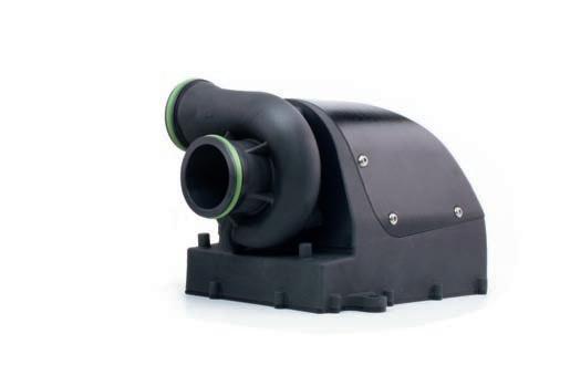


www.sobek-motorsporttechnik.de POWER DENSITY REDUNDANCY SMALL. LIGHTWEIGHT. POWERFUL. 2,5 IFC1800-1 CompetitorA 0 0,5 1 1,5 2 2,5 3 3,5 4 4,5 5 020406080100120140160 pressure[bar] flowrate[l/min] IFC8000-3 Competitor Competitor 2150g IFC 8000-3 1130 g REDUNDANCY POWER DENSITY 0 0,5 1 1,5 2 2,5 0510152025 pressure[bar] flowrate[l/min] IFC1800-1 CompetitorA 0 0,5 1 1,5 2 2,5 3 3,5 4 4,5 5 020406080100120140160 pressure[bar] flowrate[l/min] IFC8000-3 Competitor IFC 1800-1 300 g Competitor 2150g IFC 8000-3 1130 g Competitor A 1000g Our system is based on a 2 x 3-phase BLDC motor and two power controllers. HARDWARE Redundantly stored safety-relevant algorithms for controlling the motor. ALGORITHMS If a component fails, the system continues to run Redundancy is a crucial safety factor for critical peripheral components (e.g., battery coolant pumps), which will become increasingly important in the course of electrification. IFC 8000-3 POWER & SAFETY Discover our redundancy system for safetycritical applications combined with the unique power-to-weight ratio of our centrifugal pumps on the electrohydraulic pump market, which we tailor to your needs. PUSH TECHNOLOGY TO THE LIMIT
Beyond BEV

As OEMs and racing bodies look for an alternative to pure battery electric, hydrogen propulsion concepts are developing fast. Racecar looks at the current state

of play
By Lawrence Butcher
Battery-powered electric vehicles (BEVs) may be the enfant gâté as the world transitions to low-carbon propulsion, but talk to most experts with a realistic view on decarbonisation and they will assert that BEVs are far from a catch-all solution. The raft of issues surrounding everything from sourcing materials such as lithium and cobalt, through the sticky subject of what to do with batteries at end of life – not to mention the sheer size of packs needed to extract reasonable range from vehicles – mean that adding batteries to everything from scooters to boats and ’planes is simply not a sustainable option.
The reality is that (notwithstanding politicians being unable to understand more than one solution) BEVs will be part


of a wider range of low-carbon solutions, incorporating both synthetic fuels and, the subject of this article, hydrogen.


The development of what is referred to as the ‘hydrogen economy’ is already well underway, though admittedly at different rates across the world. In some places such as Japan, the implementation of widespread hydrogen infrastructure is progressing at pace. For Europe, progress is slower, but gathering momentum with most countries, and the EU, having now developed hydrogen roadmaps.
The benefit of hydrogen from an emissions perspective is that when combusted (in an ICE) or reacted (in a fuel cell), the only significant by product is water (though NOX can be an issue when used in combustion engines).

The principle of operation is similar to that of a battery, featuring an anode and a cathode, but utilising the inherent chemical energy of the hydrogen

TECHNOLOGY | HYDROGEN 30
Diagrammatic representation of a proton exchange hydrogen fuel cell
GCK Motorsport’s e-Blast racer has an electric battery and hydrogen fuel cell on board and was showcased at the 2021 Dakar Rally to demonstrate the application of fuel cell technology in racing. The French company’s updated version, e-Blast H2, was presented in prototype form at last year’s event, and will race competitively in 2024
» The benefit of hydrogen from an emissions perspective is that when combusted (in an ICE) or reacted (in a fuel cell), the only significant by product is water


31
The first hydrogen-powered entry on the Dakar Rally was the H2 built by Gaussin of France. It featured a 380kW fuel cell, 82kWh battery and twin 300kW motors. It successfully completed the 2022 event


However, despite hydrogen being the most prevalent element in the universe, it tends to be fixed in compounds and needs to be separated out. The two most common methods used for this are steam-methane reforming (SMR) and electrolysis, both of which require considerable amounts of energy. Depending on the source of that energy determines how ‘clean’ is hydrogen from an emissions sense.
Grey, Blue and Green
Where non-renewable energy is used for SMR (think coal or gas power stations), one obtains Grey hydrogen. If the SMR process uses carbon-capture techniques, the resulting gas is called Blue hydrogen. Lastly, if electrolysis powered by carbon-neutral, renewable energy is used, Green hydrogen is the result.
Currently, most of the world’s hydrogen is Grey, but considerable efforts are underway to transition to Blue and Green production methods. Of course, using energy to refine hydrogen is less efficient than simply putting it directly into a battery (SMR is around 65 per cent efficient, the latest electrolysis plants around 80 per cent), but the benefits of having a relatively easily transported energy storage medium are considerable. Not least because many of the best locations for renewable energy generation are not
in parts of the globe where that energy is most needed. The coastline of South America, for example, for wind generation, or the deserts of Africa for solar. Convert that energy into hydrogen, or a carrier medium such as ammonia (which is easier to liquefy at just -33degC and contains 1.7 times more hydrogen per cubic metre than liquefied hydrogen) and it can be shipped around the world in bulk carriers.
Pound for pound, hydrogen also has higher energy density than even the latest battery technology, 35,000W/kg compared to the lithium-ion technologies at around 4-500W/kg. So, if you can compress it enough (or store it as liquid), greater range can be extracted from a hydrogen-powered vehicle at a lower weight than a BEV. Hydrogenfuelled vehicles can also be refuelled at a much faster rate than a BEV can be charged.
Hydrogen in motorsport
Thanks to these advantages, hydrogen is firmly in the sights of a number of OEM vehicle manufacturers, with even greater interest being shown for freight vehicles and aviation. Inevitably too, various hydrogen-fuelled motorsport endeavours are currently underway as well.
The forms of hydrogen propulsion relevant to motorsport can be broken down into two classes: hydrogen fuel cell-powered
EV (FCEVs) and hydrogen-fuelled ICE. Both approaches are being deployed in racing currently but, for the purposes of this article, we will focus on the former. One can already buy FCEV road cars in the form of the Toyota Mirai and Honda Clarity, and FCEVs have competed in a number of racing disciplines.
With trucks, the area of transport where fuel cells are being adopted more widely, it was fitting that the first hydrogen entry on the Dakar Rally be a truck produced by French specialist vehicle manufacturer, Gaussin.
Its H2 Racing Truck finished the 2022 Rally and features a 380kW fuel cell coupled to an 82kWh battery and a pair of 300kW motors, all housed within a lightweight
TECHNOLOGY | HYDROGEN 32
» The forms of hydrogen propulsion relevant to motorsport can be broken down into two classes: hydrogen fuel cell-powered EVs and hydrogen-fuelled ICE


www.racecar-engineering.com 33 24 Hour Race Proven. Again. And Again. And Again. Contact us to learn more about our cellular telemetry solutions cntrl.io win@cntrl.io In 2020 Control Race Winning Telemetry helped its customers power to victories in the 24 hours of Daytona, Le Mans, Nurburgring and Spa-Francorchamps. #PowerToThePitwall WE KNOW YOUR ENGINE OPTIMIZE IT! CONTACT US FOR FURTHER DETAILS E AUTOMOTIVE@RWBTEAM.EU. | T +31 (0)252-687 713 | RACEWINNINGBRANDS.EU YOUR PERFORMANCE PARTS CENTER LARGE STOCK FAST DELIVERY EXPERT STAFF
‘skateboard’ chassis developed specifically for hydrogen-based electrification.
Also set to compete on the Dakar in 2024 is a fuel cell-powered car under development by GreenKorp Connection (GCK), headed by French Rally driver and skier, Guerlain Chicherit. The e-Blast H2 is being developed with input from advanced powertrain design specialist, FEV, and will feature a bespoke fuel cell and storage tank system.
Scuderia Cameron Glickenhaus is also working on a fuel cell power entry for the Baja 1000.

Currently competing in a more traditional track setting is Franco Swiss firm, GreenGT, running a FCEV Prototype with the Michelin Le Mans Cup as a test bed for the ACO and FIA’s future H2 hydrogen class at Le Mans, which we will return to in greater detail shortly.
Fuel cell technology

First, though, it is worth looking at what a fuel cell is, and how it works. Invented in 1839 by Welsh scientist, William Robert Grove, the principle of operation for a fuel cell is much like that of a battery, featuring an anode and a cathode and utilising the chemical energy of, in this case, hydrogen.
In a hydrogen fuel cell, the anode and cathode are surrounded by electrolyte and
a catalyst at the anode separates hydrogen molecules into protons and electrons. The protons move through the electrolyte to the cathode, while the electrons pass through an external circuit, creating a flow of electricity. Once the protons have reached the cathode, they combine with oxygen, creating water and heat as by-products of the process.
There are a variety of different fuel cell types available, but those of greatest interest for automotive, and motorsport, rely on Proton Exchange Membrane (PEM) technology. PEMFCs have a number of desirable attributes. For example, they operate at relatively low temperature (under 100degC), have high efficiency and can be started up and shut down rapidly.
A PEMFC uses a polymer electrolyte for conducting the protons, such as perfluorosulfonic acid, in the form of a membrane, onto which is painted the catalysing anode and cathode material (normally platinum particles in a carbon support). This assembly is sandwiched between gas diffusion layers (GDL), which facilitate the transport of reactants to the catalyst layers and the removal of water.
The resulting layered component is known as a membrane electrode assembly (MEA). Multiple MEAs are assembled in series using bipolar plates, increasing the output voltage to a
useful level, and creating a fuel cell stack ranging in power from one to over 100kW. These stacks then tend to be bundled together to increase system power.
A variety of ancillary systems are needed in addition to the cell stack, such as an air compressor, which pushes air through the stack supplying oxygen for the cathode reaction. Thermal management and cooling systems, as well as a DCDC converter are also used and high pressure storage tanks for the hydrogen.
Transient performance
One thing fuel cells tend not to be so good at is transient performance. Therefore most FCEVs rely on a high power density buffer battery, facilitating rapid
TECHNOLOGY | HYDROGEN 34
Franco Swiss outfit, GreenGT, has been working on a hydrogen fuel cell-powered racecar for years. In this early iteration, the fuel cell was linked to the traction motors
» One thing fuel cells tend not to be so good at is transient performance, therefore most FCEVs rely on a high power density buffer battery
changes in power deployment as well as energy recuperation under braking.
Competition ready, the car fielded by Green GT in the Michelin Le Mans Cup is a good example of the current state of the art for high-power fuel cell integration.
The ACO has set its sights on establishing a class for hydrogen fuel cell cars at Le Mans in 2025, and part of its plan to achieve this is via a partnership with GreenGT, which has been working on the development of a hydrogen fuel cell racer for many years.
The company’s test mules have evolved considerably from the rather wild-looking H2, which was intended for a Garage 56 entry in 2013, and it
now has a fully operational racecar based on an ADESS LMP3 chassis.
Over the last decade, the company has steadily increased the potency of its fuel cell package, both upping the power and reducing its size and weight. The first iterations used a road car-derived fuel cell with 18 stacks, while the current system uses a more active surface chemistry on the fuel cell membrane and only features four stacks, with an output of 250kW. While versions of the old cell were higher power, developing up to 320kW, weight has been reduced from 400kg to the current cell’s 133kg.
The fuel cell is fed air via a high efficiency compressor and a buffer battery between the cell, while the four electric traction motors allow for regenerative braking and storage of energy from the cell when it is not immediately required. The car is fuelled with gaseous hydrogen, rather than liquid.

The company’s early cars had the fuel cell linked directly to the traction motors. But by adding a battery into the system, it was possible to double the energy available for the motors at peak demand. The 2.4kWh battery can deliver 300kW over 20 seconds.
The company worked with a Formula 1 battery supplier on the development of the buffer and, with power rather than energy density the priority, was able to achieve an astounding 150 C-rate.
Packaging and weight
‘The main target we have at the moment is to reduce the weight of the system, which is critical. We are not touching the fuel cell itself, because over the last four years it has proved very stable,’ explained Jean-François Weber, MD and head of R&D at GreenGT, speaking at Le Mans this year.


‘We have focussed our work on the accessories – things like the compressor, the cooling – and the aerodynamics of the car.’
It is notable that the fuel cell element of the GreenGT is considered adequate in terms of performance, with the main challenges now being keeping other components cool and packaging everything within the constraints of a Sports Prototype chassis.
Let’s be clear though, the cooling demand of the battery and motors at full power is considerable.
35
GreenGT has been developing its fuel cell package, increasing power and reducing size and weight, down from 400kg to 133kg in this iteration. Power output is 250kW
» The ACO has set its sights on establishing a class for hydrogen fuel cell cars at Le Mans in 2025
‘When we combine the fuel cells and battery, we are near 500-520kW,’ says Weber. That’s why the car features a somewhat unusual, roof-mounted scoop for supplying cooling air to the motors and battery. Due to the sidepods being occupied by a pair of hydrogen tanks, there is only space in the sides for the fuel cell cooling circuit, hence the need for the additional roof scoop. ‘We need to re-think the definition of the cars and where we put the various components,’ suggests Weber.


The fuel cell is due for further development, both to cut its weight and increase performance. ‘We started four years ago on [the development] of composite bipolar plates, and on the MEA we have
some developments to improve the active surface, but we cannot give more details on that yet,’ says Weber. ‘We hope to reduce the volume by 30 per cent and improve the weight by efficiency. We are at the point where we can compete with IC engines and the curve for development is very steep.’
Currently, the team is limited in how far it can go with overall vehicle architecture changes as the existing fuel tank design is the only one homologated for racing.‘ With the regulations, we cannot do everything we hoped we could,’ muses Weber.
Looking to the future, though, there are several promising options that should make packaging hydrogen tanks less burdensome.
TECHNOLOGY | HYDROGEN 36
» ‘We need to re-think the definition of the cars and where we put the various components’
Jean-François Weber, MD and head of R&D at GreenGT
GreenGT had this FCEV Sports Prototype running at Le Mans last year as a test mule for the ACO and FIA’s proposed H2 hydrogen class, which is scheduled for Le Mans competition in 2025
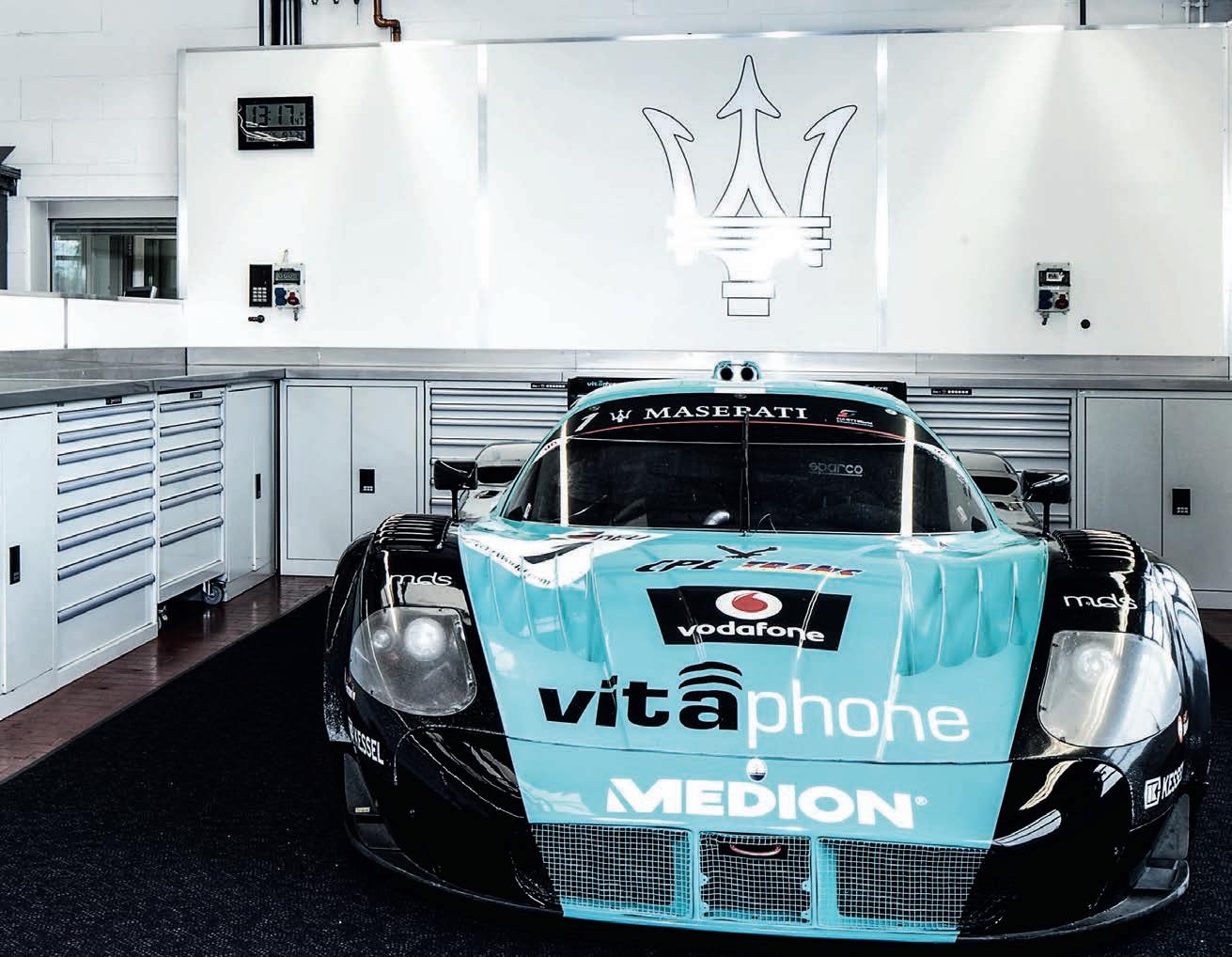


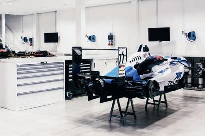


www.lista.com BENEFITS + Proven expertise Many years of experience equipping all areas of Motorsport + Modular design Universal modular system + Top industrial quality 10 Year guarantee + Customisation Define your exact requirements + Completely universal From a single mobile cabinet to full facility fit out LISTA STORAGE SOLUTIONS FOR MOTORSPORT CALL US NOW OR SEND AN E-MAIL 01908 222333 info.uk@lista.com
For example, a UK-based company called Viritech, with former F1 engineer, Mat Faulks, as its CTO, has patented a design for structural tanks. Produced from a graphene composite, the tanks are intended to act as stressed members, allowing for better integration into a vehicle and a considerable weight reduction.
A move to cryogenic-cooled liquid fuel would also greatly reduce the tank size needed to achieve representative stint lengths at a track like Le Mans. ‘The volume would go down three to five times,’ observes Weber.
Thanks to liquid hydrogen being stored at much lower pressure, the need for cylindrical tanks is also removed, adding further packaging flexibility. Though the industry standard for automotive currently centres around gaseous hydrogen, moves are afoot, particularly in the freight sector, to develop liquid fuel systems and infrastructure.
It is notable too that in Japan, Toyota is progressing with work on a
mobile liquid refuelling system for its hydrogen-fuelled ICE Corolla, currently racing in the Super Taikyu series.

The Japanese company has also been pushing the capabilities of gaseous refuelling. For example, by increasing the size of the car’s fuel port and nozzle, coupled with a rise in pressure from 40MPa to 60MPa, it can now fill the car’s twin tanks in around one and a half minutes, compared to five minutes when the project commenced in 2021.
Development rate
The efforts of GreenGT and others across different motorsport genres will, it is hoped, accelerate the development rate of hydrogen fuel cell systems. However, suitable regulation and the infrastructure to make it work on a larger scale lags behind the currently available technology.
Regulation constraints have already slowed the development of innovative storage solutions for GreenGT, while trackside infrastructure needs considerable
investment if hydrogen-fuelled cars are to compete in significant numbers. Taking Le Mans as an example, the bunkering required to provide petrol for a grid of 60+ cars is huge, and even just the installation of hydrogen tanks and supply lines for five cars would be a major undertaking, let alone a full grid. But, if 2025 remains the target for an H2 class, such work will need to begin soon.
Hydrogen almost certainly has a future in motorsport, but regulators and race series organisers need to remain flexible for the technology to prove its potential. l
TECHNOLOGY | HYDROGEN 38
» Regulators and race series organisers need to remain flexible for the technology to prove its potential
Toyota has been pushing ahead with its hydrogen project, competing with a hydrogen-fuelled ICE Corolla in the Super Taikyu series, and developing this mobile liquid refuelling station


Formula E is looking to reinvent itself as it approaches the milestone of a decade in international motorsport
 By Sam Smith
Third gen-E-ration
» Gen 3 has arrived, and it’s a very different looking beast indeed, one that behaves like an entirely separate species to its popular predecessor
FORMULA E | GEN 3 40
Initially given little chance to survive when first mooted in 2012, the allelectric series has blossomed into a fully-fledged world championship with multiple prestige OEMs and a roster of driving and engineering talent that makes it both one of the strongest and most lucrative forms of motorsport outside of F1.


Technically, its road map has been adaptable, and its sporting structure flexible enough to contend with some serious slings and arrows that have ranged from the widespread ridicule of changing cars between 2014-’18 and the debacle that saw cars running out of useable energy at Valencia in April 2021’s infamous ‘zombie race’.

The Gen 2 car, a distinctive mix of single seater and Prototype, was widely lauded for its striking looks and its propensity to create close (sometimes too close) racing. Now, Gen 3 has arrived, and it’s a very different looking beast indeed, one that behaves like an entirely separate species to its popular predecessor.
Tender process

The new car was born in much the same way as its predecessor, via official FIA tenders that were sent out in 2019. By early the following year, Williams Advanced Engineering had regained the battery deal it lost to McLaren Applied for Gen 2 and Spark had retained the chassis and other central components, such as the front MGU, which was allocated to Atieva (Lucid Motors’ tech’ arm).
But by far the biggest shock was Michelin not being kept on for a third term as tyre supplier. Instead, Hankook came on board.
And while the technical parameters around the hike in power from 250kW to 350kW and an impressive maximum 600kW regen’ capability stole the headlines, the new rubber is a popular topic of conversation as the opening round, scheduled for midJanuary at the Circuit Hermanos Rodriguez in Mexico City, looms on the horizon.

The Gen 3 car is lighter, shorter, narrower and quicker than its predecessor. By how much is still open to debate, but it’s a faster car, with initial expectations of a top speed just under 200mph. Add in around 95 per cent power efficiency from an electric motor delivering up to 350kW of power (equivalent to 470bhp), and things are looking exciting.
These significant changes inevitably alter things from a design point of view, as Jaguar’s technical manager, Phil Charles, notes. ‘It’s a very different game now in Gen 3,’ he says. ‘There’s some really ambitious targets in there.
‘The Gen 3 [car] is about 50kg lighter than the Gen 2 and, at the same time, you’ve added a front powertrain to the car. There is this extra really cool bit of tech’ yet the car has been put on a massive diet.
‘These are ambitious targets, a big step for the car, and a big step for the drivers to have to deal with all that extra stuff.’
The new front powertrain, which is said to be a simple enough spec MGU, ensures the regen’ on the front axle adds what Charles describes as ‘a big extra dimension.’
‘It’s pushed all the parameters in the car, including the battery target, as we have a really lightweight battery [285kg compared to Gen 2’s 385kg] and it’s got fast charging, too,’ he adds.
But what does that mean from a design standpoint for the manufacturers, of which there are six – DS, Mahindra, Nissan, Jaguar, Porsche and NIO 333?
Power increase
‘Just that power increase on its own is big, but also the car is 100mm narrower and 140mm shorter, so it’s a much nimbler car,’ continues Charles.
‘That means the frontal area that’s cutting through the air is also smaller, so that changes the aero parameters on the car a bit, too.
‘The front tyre is now an open wheel again. There’s normally a fairly significant change in the way a car behaves when you cover a wheel, so when you uncover it there’s a lot of eddies that flow off the wheel and that affects cooling into the radiators.
‘We’re excited because the car is a big integration task. Now there’s a brake-by-wire system and front power chain kit that we have to communicate with, so we’ve got to get all of that working together. In terms of bringing all those bits together, it’s a big job.’
The manufacturers went through a major simulation process when the initial spec of the Gen 3 cars became known in 2019 but, with a new tyre manufacturer coming in, they were a little hamstrung on the vehicle dynamic elements needed for preparation purposes.
The regen’ capabilty of the new car is so impressive (up from 250kW to 600kW) that it has no hydraulic rear axle braking, which adds to the learning curve for drivers, too
41
Before they could start making decisions on what rear MGU they designed, and what overall powertrain cluster was drawn up, manufacturers needed to work out some of the basic parameters.
‘We need to know the tyre, we need to know a bit of aero, and we need to start to do some simulation and work out, first of all, what top speed we’re going to do,’ confirms Charles.

‘Then you need to look at what maximum torque we’re going to get from the tyre. That then unfolds and dictates the MGU design because once we’ve got a peak torque and a top speed, we can decide lots of parameters in the MGU.’
Packaging job
Only after all that was achieved could the packaging strategies begin. The Gen 3 car has some very different constraints with the suspension, especially given the new front powertrain.
Putting a motor in a relatively small cross section of a monocoque is always tricky but, according to Charles, the work that’s been done by Spark and Atieva is ‘actually pretty good’ because ‘they’ve basically made it in a sympathetic way so that the front powertrain kit can be extracted in one very compact, integrated lump.’
That ‘lump’ includes the front differential, inverter and motor, but there is still complexity in bleeding and disconnecting the cooling system, which means there will definitely be more to do for mechanics working in the series.
In collaboration with the front and rear powertrains, the new Hankook tyres will be crucial in the overall process of understanding how to get the best out of the Gen 3 car.
‘Over the last few years, it’s been really good to have the same tyre manufacturer. Now, just changing the tyre is a big change – it’s always a tricky thing for a new tyre manufacturer to come into – but given the step change of power, while maintaining basically the same concept,

Testing


the fact
with no
made
an unknown
data to
which is a relatively narrow wheel for a racecar and a single compound that can do all conditions, that’s really quite tricky.
‘We had to get our heads around the fact that both the tyre manufacturer and philosophy was changing.’

Educated guesses
Essentially, the manufacturers have had to make educated guesses at what cycle they expect the new car will go through.
Overall length 5200mm 5016.2mm
Overall height 1063.5mm 1023.4mm
Minimum weight (including driver) 900kg 840kg
Max power 250kW (335bhp) 350kW (470bhp)
Will it be braking harder? Or from a higher speed? Is it likely to be coasting for longer?

‘Then you start to say, right, what characteristics on the suspension do I want the car to have to complement the tyre and all those extra packaging bits,’ says Charles. ‘Things like not having hydraulic brakes on the rear means the forces go into the car in a different way.
‘Now you’re pinching the axle in the middle of the car. That puts different forces
Powertrain configurationRear only Front (spec) and rear (manufacturer)
FORMULA E | GEN 3 42
Comparison of Gen 2 and Gen 3 car specs Gen 2 Gen 3
Overall width 1800mm 1700mm
Wheelbase 3100mm 2970.5mm
Max regen’ 250kW 600kW Energy recovery 25% 40% Top speed 280kmh / 174mph320kph / 200mph
»
‘We had to get our heads around the fact that both the tyre manufacturer and philosophy was changing’
Phil Charles, technical manager at Jaguar
has been
more difficult by
the new tyre is
quantity,
track
work with The Gen 2 cars had enclosed front tyres and a larger frontal area, so the Gen 3 car is a whole new aerodynamic proposition
Not only is the Gen 3 car narrower, shorter, more powerful and some 50kg lighter than the Gen 2, it now has a front MGU and a new tyre supplier in Hankook, so plenty for engineers and teams to get their heads around

43
to the suspension. It’s a very different load transfer through the car, through the suspension, through the wishbones and into the main case.’

It’s certainly going to be a fascinating aspect of how teams and drivers use their cars on the wide variety of temporary and semi-permanent venues Formula E uses.
The manufacturers received their single test and development cars from Spark Racing Technologies in May, yet such was the pace of the final races of 2022 (eight races from June to August) that only a modest amount of running was achieved by the end of September.


Group test
A group manufacturer test was therefore arranged for mid-September where, among other things, the first fast charging pit stops were trialled and a problem with the cells of the spec RESS are believed to have been investigated further.


The manufacturers had just two months until the traditional pre-season test in Valencia, in which to complete the homologation of the cars, which will then be locked in for the first two seasons of the Gen 3 rule set through 2023 and 2024.
With all the brake systems around the regen’ now being different, Charles thinks it unlikely any team would be in a position at present to claim all their systems are perfect and they’ve got their car balance spot on. It’s a big learning curve for all involved.
Much of which will inevitably come back to the vehicle dynamics, and how they are adapting to the Hankook rubber, which is so far said to be highly durable.
‘It has a low wear rate,’ says Charles. ‘That’s a risk for them coming into that big step up in power, and also not knowing the tracks.
‘Formula E is very specific, and the tracks we go to over the course of a season are very different. It can be a car park surface one month, and a street surface the next, it’s a real mix of surfaces and they’re all very different to a normal racetrack.
tyres are said to be very durable, but only one compound is allowed and there are multiple track surfaces
‘They must have taken a view that they haven’t got that data set. They haven’t gone and tested because you can’t get access to a track. You can’t go to New York, have a look, and measure that great big shipping area.’
New and improved
It won’t just be the power, energy and tyres that will be new and improved for Gen 3 racing. Finally, Formula E will have driveshaft torque sensors fitted, similar to those being used in the Hypercar era of endurance racing, which contribute to the BoP process.
Supplied by MagCanica, the sensors are fitted directly onto the driveshaft using a bearing-grade plastic. The torque sensor

FORMULA E | GEN 3 44
Further technological developments include brake-by-wire, recycled carbon fibre and driveshaft torque sensors, with four-wheel drive on the horizon
» ‘It’s a very different load transfer through the car, through the suspension, through the wishbones and into the main case’
Phil Charles, technical manager at Jaguar
With battery cooling less of a concern in the Gen 3 package, aerodynamics have taken on a more familiar form
The Hankook
The Gen 2 car was introduced for season five (2018) and had better battery capacity than Gen 1. Cooling was an issue though, and played a significant part in the design of the car


housing is axially constrained using a groove in the housing that interfaces with a mating feature on the sensor housing.
The system has extensive magnetic shielding, integrated seals and cutting-edge electronics and firmware that achieves 0.25 per cent in-vehicle accuracy. Only DC power needs to be provided, and the measured torque signal is returned over CAN, along with additional diagnostic information.
‘In our case, they’re going to be used more for what we call ‘a tunnel’, so they’re more a control window for us to work within,’ explains Charles. ‘It’s a slightly different usage, but the technology is proven, and it should work well.
‘There’s a little bit of integrating required for the extra kit, but they fit nicely towards the outboard end of the driveshaft with a measurement sleeve almost that goes around the centre.’
While the manufacturers work flat out to get their Gen 3 packages ready to be homologated in the first week of November, some are openly talking about the possibility of developing an evolutionary package for the final two seasons of the forthcoming rule set, 2025 and 2026.
Thoughts on racing without brakes!
The Gen 3’s maximum regenerative braking capacity of 600kW means a first for a very long time in a racecar, the rear axle of the Gen 3 will not feature hydraulic brakes at all.
Despite being slightly apprehensive about this prior to his tests in late 2021 and early 2022, Formula E test driver and three times Le Mans winner, Benoit Treluyer, was effusive in his praise for the speed reducing characteristics of the Gen 3 test car.


‘It’s a really big change in motorsports, without the [rear] brakes and all the things we have to develop in software and things like that, so it’s a big work we have.
‘I was really impressed because the bite really felt like a normal brake, and I couldn’t believe it wasn’t at the beginning.
‘The good thing is you can use this system very well to handle the car on the brakes and to set up the car, so it’s a really interesting development.’
Treluyer then went one better, saying, ‘It’s actually better than the normal brake, because it’s very consistent and it’s not like you have to play with the temperatures and set up the cooling, which is really good.’

He then said he felt he could work to a ‘new window’ in terms of handling.

‘In the past in Formula E, the brakes were a bit of a problem to keep in the right window, but this system is actually a really good tool to work with,’
Overall set-up is therefore likely to be even more crucial with the Gen 3 car than it has been in previous generations of Formula E, but again Treluyer was positive about the challenge: ‘Every time we’ve made a small adjustment, the car has answered really well. It’s actually very good to drive and to set up.
‘And then to enter a corner and control the brakes going into the corner is quite easy if you set the car up really well.’
45
The FIA is known to have evaluated the possibility of a Gen 3 evo model to run in full four-wheel-drive spec, but a decision is not expected to be taken until the summer of 2023 at the earliest.
The front MGU is said to be entirely capable of being used for traction purposes, as well as regenerative, but further studies of thermal considerations are likely to be needed before achieving a 4WD possibility for the second half of Gen 3.
Environmental impact
The sustainability credentials of the Gen 3 will also see Formula E go up a notch with responsibly sourced minerals contributing to the RESS, while the battery cells are set to be re-used and recycled. Materials such as linen and recycled carbon fibre will also
be used for the first time in single-seater bodywork construction, with the cars featuring recycled carbon fibre from retired Gen 2 cars. This, says Formula E, ‘will reduce the carbon footprint of the production of the Gen 3 bodywork by more than 10 per cent. All waste carbon fibre will be re-used for new applications through adoption of an innovative process from the aviation industry.’
Meanwhile, natural rubber and recycled fibres will make up 26 per cent of the Hankook tyres, all of which will be recycled after racing.

The carbon footprint of the Gen 3 car has been measured from the design phase
The challenges ahead for WAE
In pitching for the battery supply deal for the Gen 3 car, Williams Advanced Engineering (WAE) had to take on board a large number of criteria, not least the ability of its RESS (rechargeable energy storage system) to be fast charged.

‘They’ve had to pick a cell type, believed to be initially Total SAFT derived, and a cooling system that can facilitate a 600kW charge rate, in addition to a lot of additional regen’ via the front axle,’ notes Phil Charles, technical manager at Jaguar.
Last year’s Gen 2 Formula E saw a certain amount of energy being regenerated on one axle, but on Gen 3 there’s a much higher regen’ cycle, and two axles’ worth of energy coming in. That means the battery has a much harder cycle to deal with, yet it is 100kg lighter than its predecessor.
The pouch-type cell that has been chosen therefore has to deal with a higher charge rate, and a really high duty cycle that the new car’s cooling system is built around. This means very different thermal properties for the teams to deal with, and the possibility that batteries will actually have to be heated up to suit a preferential usage window, believed to be somewhere between 45 and 65degC.
This is essentially opposite to the situation that occurred with the previous McLaren Applied-derived battery, which was started from a very cool temperature.
There’s already talk of a Gen 3 evo model, with 4WD a very real possibility, although a final decision won’t be made until 2023


to inform all measures taken to reduce its environmental impact, while all unavoidable emissions will be offset as part of Formula E’s net zero carbon commitment.
Backing this up, all Gen 3 suppliers are to operate in line with ISO 14001, the international standard to reduce the environmental impacts of manufacturing, and must also be FIA Environmental Accreditation 3-Star rated.
It’s clear Formula E isn’t sitting still, very far from it, and now it’s down to time to see how well teams and drivers get to grips with the series’ latest generation racer. l
‘Of course, when you put an energy through something, the thermal cycle is key, it’s not infinite,’ continues Charles. ‘But you can make something with a super heavy metallic mass, and it can be thermally very easy. We don’t because we’ve asked for a lightweight battery, all that charge rate and all those characteristics. So it will, by nature, have a thermal operating window. As a team, we’ve got to work around that.
‘We’re getting used to that in testing, used to getting up to temperature. The way you go about it is with a pump cycle, blanking and taking into account the cycle you’re going to use within the race. That’s all part of this process we’re in now and learning about.’
Testing has also thrown up some reliability concerns, with several manufacturers having private test days curtailed due to suspected cell-derived issues.


This caused Porsche’s head of factory motorsport, Florian Modlinger, to openly query the reliability of the spec parts supplied to the manufacturer: ‘The FIA is working hard with the common part supplier (WAE via Spark) to find solutions for the topics, which need to be sorted before the first race,’ he commented.
‘This is an ongoing process. From the current test we are putting a lot of mileage on the car with obviously some compromises in running for the above-mentioned reasons.’
FORMULA E | GEN 3 46
»
The carbon footprint of the Gen 3 car has been measured from the design phase to inform all measures taken to reduce its environmental impact
BUILDING ON OUR RACING LEGACY

We are proud of our technical partnership with the iconic Scuderia Ferrari. For over five years, Öhlins Racing has been developing and supplying suspension for the Scuderia Ferrari cars, providing advanced technical and support when needed. Our goal is to ensure the drivers experience the best possible suspension perfor mance during every race – no matter how extreme the conditions get.

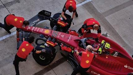
OHLINSRACINGAUTOMOTIVE 410 WORLD CHAMPIONSHIP TITLES, AND COUNTING ÖHLINS RACING AB • Instrumentvägen 8-10 s-194 51 Upplands Väsby Sweden +46 8 590 025 00 • ohlins_se_info@driv.com
The road to recovery
 By Gemma Hatton
RECYCLING | BATTERIES 48
With the rise of electric vehicles now accelerating, finding a solution to the problem of recycling millions of batteries is paramount
biggest challenge when recycling batteries is understanding their state of health. This is currently made difficult because manufacturers and race teams want to protect the IP within the BMS. Formula E battery pictured
The UK government announced in 2021 that the sale of all new petrol and diesel vehicles would be banned from 2030 onwards, with only significant hybrids allowed to 2035.
Other countries continue to follow suit as the world pushes towards the targets set out in the Paris Agreement, which aims to keep the global average temperature increase below 2degC per year.
With both countries and car manufacturers continuing to ban internal combustion engine vehicles from their repertoire, the reliance on electric vehicles (EV) is growing. Experts are now predicting there could be over 140 million electric cars on the world’s roads by 2030. This expected boom will leave us with over 11 million tonnes of used lithium-ion batteries that need to be recycled between now and 2030, so researchers across the globe are racing against time to develop an efficient and economic automotive battery recycling process the world can quickly adopt.
So why is recycling batteries suddenly so important? ‘As batteries continue to appear in vehicles, we’re moving from batteries that weighed 100g in a ’phone to something that weighs 100kg, or even 1,000kg,’ highlights David Greenwood, professor at Advanced Propulsion Systems, WMG at the University of Warwick. ‘Those batteries embody large amounts of valuable and sometimes rare materials. To extract those is expensive, and can be harmful to the environment if done wrong.

‘Therefore, as we move into this kind of second generation of electric vehicles, it’s important that we’re not continuously reliant on the extraction and refining of new materials, but instead are reclaiming materials from the waste products of the previous generation of batteries.’
From a carbon footprint perspective alone, recycling is a better alternative to mining, as Kristof Gabriël, commercial director refining and recycling at Umicore explains: ‘In general,
49
» ‘It’s important we’re not continuously reliant on the extraction and refining of new materials’
David Greenwood, professor at Advanced Propulsion Systems, WMG at the University of Warwick
The
external studies show that recycling has an environmental benefit vs mining when it comes to CO2. Perhaps a better way of looking at it is the difference between the units of CO2 required to mine a unit of metal and the CO2 required to recycle it. Here the savings are significant. The CO2 footprint is limited, and there is not a lot of CO2 / weight.’
Life cycle emissions
The processes involved in manufacturing a battery are complex, expensive and account for a large proportion of the life cycle emissions of an electric car. Batteries are born out of lumps of rock that have been mined and refined into raw materials. The raw materials are then combined to form the active powders or electro-chemical components of the battery. These can consist of materials such as graphite, along with metals including nickel, cobalt, iron phosphate, manganese and aluminium.

The active powders are then coated onto thin foils, typically made from copper or aluminium, and form the anode and cathode electrodes. Between these electrodes is typically a thin polymer ‘separator’ soaked in electrolyte. The foils are then either rolled up like a swiss roll and put into a can to create a cylindrical cell or stacked on top of one another like the pasta in a lasagne and put inside a pouch to make a pouch cell. The cells are then grouped into modules, which are used to build up a battery pack.
The contact between the surface areas of all those components allow for an electrochemical reaction where lithium ions are transferred between the anode and cathode, releasing and absorbing electrons as they do so and converting stored chemical energy into useful electrical energy.
‘Just over half of the value of a battery is in the cells, which are the fundamental building blocks of the battery. The remainder is in the conversion of the cell into the pack with all the management systems,’ explains Greenwood. ‘When you look inside the cell, about half of the value of that cell is the cathode active material. That’s where the greatest value effectively lies.’
Intellectual property
Before a used battery can begin its road to recovery, its state of health needs to be fully understood. This is a major challenge as, currently, there is no standardised way of doing this because each battery’s BMS (Battery Management System) is a crucial part of its manufacturer’s IP.
‘That is something they [battery manufacturers] regard as being highly proprietary, and they all spend a fortune on developing it because that’s what allows them to either use a greater or lesser capacity of the battery during its life, which gives more or less range for the user,’ highlights Greenwood. ‘So manufacturers are very defensive of that IP as it’s part of their USP.’
With the BMS unable to tell recyclers the status of the battery, alternative test methods have had to be developed in order to establish its condition. ‘When a battery comes into the recycling chain, it is a box with two terminals and somebody has to work out what state it’s in,’ explains Greenwood. ‘Typically, you have to conduct a full charge and then a full discharge to measure how much energy went in and how much energy came out. This can then be compared to the original specification of the battery, which details the performance of the battery when new. But this is an extremely expensive and time-consuming process.

‘The ability to very quickly identify what the battery is, and what state it’s in, would make a significant difference to the recycling process. So having a BMS that can act as a sort of passport for the battery, showing its current state of health, what it looked like when it was new, what it has done since then, what it might be useful for now and, more importantly, the chemistry inside it.

RECYCLING | BATTERIES 50
» Manufacturers are repurposing batteries to power street lights and back up lifts
WMG at the University of Warwick collaborated with the UK energy storage laboratory on a project that reduced the state-of-health testing time on batteries from three hours to three minutes
This will help recyclers as they store batteries in groups of similar chemistries and then process them in batches to obtain a high yield of a particular material.’
Life cycle analysis
From a life cycle analysis point of view, the ideal solution is not to dive straight into recycling, but actually utilise used batteries in second life applications. This is where a battery pack that is no longer suitable for one application is re-used for another.
As battery packs are charged and discharged, the overall performance degrades, which means there is less stored energy available for generating power. In the case of electric vehicles, the end of life is typically when the battery has degraded by around 20 per cent. Therefore, the rest of the battery’s capacity can be utilised for lower power, less demanding applications such as domestic energy storage.
Manufacturers such as Nissan are repurposing batteries to power street lights in Japan, while Renault uses old batteries to back up lifts in Paris.
‘When we talk about a battery having an 80 per cent state of health, what that means is it can store about 80 per cent of the capacity it used to,’ explains Greenwood. In other words, if you have an electric vehicle, the range is about 80 per cent of what it was when it was brand new. That might lead you to think that it’s hardly degraded at all, which is sort of true. However, the degradation of electric vehicle batteries is only linear until 80 per cent. After that, it can drop off dramatically. By taking that battery out of the vehicle and implementing it into a more benign use case, the degradation from 80 per cent to 40 per cent is much slower, so you can get much more life out of it.
Giving batteries a second lease of life in this way not only enables companies to benefit from the same product several times over, it also displaces the need for new batteries. Furthermore, with only a few conversion processes required, this strategy retains the maximum amount of value that was originally embedded into the battery during its manufacture.

‘You can get another five to 10 years’ life out of the battery before you have to move to recycling,’ says Greenwood. ‘That really helps in terms of life cycle emissions because you’re having a whole second use from that same
initial investment. So, second life applications are always the first thing we look for.

‘But when batteries have completed their second life, or if they are not suitable for that, we still need processes that allow us to access those valuable materials.’
The next level then is re-manufacturing. This uses the same principles as having an engine rebuilt. If a battery fails due to one module, this can be replaced and the battery pack, as a whole, can continue running. ‘In terms of re-manufacturing old batteries, there are no moving parts so, generally speaking, all the expensive parts within a battery degrade at the same rate,’ continues Greenwood. ‘You may find some companies replacing an odd module to extend the life of a battery for a year or two, but I think re-manufacturing is a short-term opportunity.’
A longer-term solution is recycling, and currently there are several approaches that can be taken, with new technologies being researched all the time.
The recycling process
The first stage to recycling is pre-treatment. This is essentially where the battery is disassembled, which is not an easy process given the complexity of modern batteries. Technicians, or even robots, can manually dismantle the modules, separating the main circuitry from the cells. These are then fed into a shredder, and a separator deciphers the metallic components from the polymers.
51
» In the case of electric vehicles, the end of life is typically when the battery has degraded by around 20 per cent
Formula E Gen 2 batteries utilised pouch cells and Umicore recycled all the batteries from the first two seasons of the electric racing championship
Ironically, as design innovation continues to reduce the amount of expensive materials needed in battery manufacture, the desire for recycling could diminish because there is less value to recover
A secondary treatment process then follows, which uses a chemical solvent to separate the cathode material from the aluminium foil and the anode material from the copper foil. These active materials are referred to as ‘black mass’.
The third and final stage is where the cathode material is dissolved through either thermal and electrolytic reactions, known as pyrometallurgy, or leaching chemicals, known as hydrometallurgy.
The most common approach today is pyrometallurgical, which is effectively where the entire battery is smelted at extremely high temperatures. This eliminates the organic components within the battery such as the separator and the anode, which is often carbon, and leaves a powder from which the desired metallic components can be recovered chemically. Whatever is left after the smelting process is then typically turned into fly ash and utilised in low-value applications such as building materials.
Unfortunately, pyrometallurgy does not recover such as graphite, lithium or aluminium. Furthermore, it consumes more energy than hydrometallurgical processes and so is viewed as less environmentally friendly.
However, it is cheaper and can meet today’s legislative requirements for battery recycling.
Hydrometallurgy extracts metals using an aqueous solution. First, the components are ground to a powder, which is then immersed into an acid solution with an oxidising agent if required. This is known as leaching. After that comes the purification stage, which aims to remove any heavy metals through cementation or electrochemical reduction. Finally, the desired metals are extracted from the solution.
In general, hydrometallurgy extracts metals with higher purity than pyrometallurgy, and consumes less energy, but does require significant quantities of industrial chemicals in the processing.
Hybrid recycling
Another strategy is to combine pyrometallurgy and hydrometallurgy to form a hybrid process that exploits the benefits of each, whilst minimising the drawbacks. One company utilising this approach is Umicore, Formula E’s official battery recycling partner. The pyrometallurgical phase uses Umicore’s unique UHT (Ultra High Temperature) furnace, which has been designed to safely treat large
volumes of different types of complex metalbased waste streams. The furnace is the largest dedicated recycling installation for lithium-ion and nickel metal hydride batteries in the world. With an installed capacity of 7,000 metric tonnes, this furnace is capable of recycling up to 250 million mobile ’phone batteries, or 35,000 EV batteries per year.
‘The Umicore battery recycling process combines a new treatment and recycling method with existing refining technology,’ says Gabriël. ‘Treatment includes the safe dismantling of large industrial batteries, such as EV batteries, without crushing or shredding the cells. This means operators and the environment are not exposed to hazardous battery compounds in the process.

RECYCLING | BATTERIES 52
» Hydrometallurgy extracts metals with higher purity than pyrometallurgy and consumes less energy

‘After sorting and dismantling, metals are recovered in our proprietary in-house, high-temperature smelting process. Within the smelter, battery materials are transformed into metal alloys containing Co, Ni and Cu and a concentrate containing Li and REEs [Rare Earth Elements]. This fraction is further refined for Li and REE recovery externally.
‘The process is energy efficient as it recovers the energy present in the batteries, whilst also treating potentially harmful gases.’
Umicore’s process aims to recover and recycle as much material as possible, whilst minimising the impact on the environment by utilising the energy within the battery itself in the process. ‘The plastics and other organic compounds, including solvents and electrolytes, are burned as a gas to produce heat for the process,’ continues Gabriël. ‘This gas is cleaned to ensure all organic compounds are fully decomposed, and that there are no harmful emissions.
‘The small amount of fluoride found in batteries is also collected and solidified for specialised landfill treatment. The copper, cobalt and nickel metals are refined, so they are ready to be processed as new cathode materials. The metals can be sold or used in new battery materials or other products.’
The pyrometallurgical phase of Umicore’s process effectively converts batteries into three fractions. Firstly, an alloy containing cobalt, nickel and copper, ready for hydrometallurgical processing, where this alloy is further refined to convert the metals into active cathode materials. Secondly, a slag fraction that can be used in either the construction industry or further processed for metal recovery. Finally, clean air is released from the stack after it has been treated by the UHT’s unique gas cleaning process.
Closing the loop
‘Batteries can be infinitely recycled because they are active materials based on metals and they are recyclable without quality loss,’ highlights Tom Van Bellinghen, VP OEM value chain and marketing at Umicore. ‘This means that at the end of the recycling process the metals are purer than if you would get them from a mine.
‘Umicore’s closed loop process is unique in the sense that we combine recycling of end-of-life batteries and the most stringent environmental standards, and afterwards we use these metals again to make high performing cathode materials.
‘Our partnership with Formula E proves that today electric cars are high performance and, at the end of the life, the batteries can be recycled. And doing that with high efficiency we can recover all the metals inside.’
Battery recycling has become an important consideration for the likes of Formula E as it combats the opinion that disposing of batteries is wasteful and environmentally unfriendly. The Formula E regulations under the Generation 2 spec specified that each car could only use one battery pack for the entire season. However, if there was a fault then the battery could be replaced, but this came with a 20-place grid penalty for the team, unless the issue could be proven to be the fault of the supplier.
Each Formula E team fields two cars, with manufacturers also allowed to run a test car for private testing purposes. With 12 teams involved, this equates to a minimum of 33 batteries, not including any replacements. This is a rather substantial amount for a racing category whose ethos is of sustainability. So this is why in 2019 Formula E assigned Umicore as its official battery recycling supplier.
Answering his own question, ‘what do we do with that technology, especially with those batteries after we use them?’ Alejandro Agag, Formula E’s CEO, explains: ‘The partnership with Umicore is a really important step for the ABB Formula E championship because we need to close the loop by recycling at the end of the life the batteries we use for the race.’
With several standardised battery recycling processes available that are capable of processing both low and high voltage batteries, as well as the likes of electric vehicle batteries from road cars and racecars, why then is battery recycling still not widely adopted? Well, financially speaking, battery recycling still doesn’t make sense. Each process required to build up a battery, and then tear it apart only to build it back up again is complex and expensive. Recycling needs to recover a high percentage of material, with a high purity, in an efficient, environmentally friendly and inexpensive way, and that’s not an easy challenge.
‘Recycling is not a positive value stream in most cases,’ reveals Greenwood. ‘A battery currently costs the manufacturer several hundreds of euros per tonne to recycle, because it costs money to do it and the products that you get back are worth less than the process it took to get to them.
‘It’s currently cheaper to buy the raw materials than it is to recover from a battery,’ continues Greenwood. ‘The technologies we have today are not very good at economically recovering all of the elements. So typically, the parts of the battery that people tend to focus on are the ones that give the highest commercial returns, like cobalt and nickel.’
Battery recycling makes even less financial sense when you look at recovering lower value materials such as lithium, graphite or aluminium. As a result, quite a lot of the materials within a battery are wasted because it’s cheaper to mine the virgin materials, yet this is still compliant with the regulations.
End-of-life directive
‘For passenger cars, there is an end-of-life directive that says 95 per cent of the mass of the vehicle has to be recovered or re-used,’ explains Greenwood. ‘Roughly speaking, 85 per cent of that mass has to be used as materials, and 10 per cent of it is allowed to be burned to create the energy required to drive the recycling processes. So the low value stuff that is not worth recovering is turned into heat, which drives the recovery of the higher value materials.
‘However, an electric vehicle battery is covered by a separate battery directive, which specifies that 50 per cent of the mass of the battery must be recovered. That means that it is a lower threshold than the rest of the vehicle. Given that a typical battery weighs approximately 400-800kg, that means there is still 200-400kg of material that does not need to be recovered according to the regulations.
‘With the battery case accounting for a significant portion of the overall weight of the battery, that is usually the first thing manufacturers recycle because it’s relatively easy to deal with.’
RECYCLING | BATTERIES 54
»
‘At the end of the recycling process the metals are purer than if you would get them from a mine’
Tom Van Bellinghen, VP OEM value chain and marketing at Umicore
»
‘The low value stuff that is not worth recovering is turned into heat, which drives the recovery of the higher value materials’
David Greenwood, professor at Advanced Propulsion Systems, WMG at the University of Warwick
However, recent research projects from the Warwick Manufacturing Group show that around 80-85 per cent of the mass of the battery might be recoverable in a way that is economically viable. Beyond 85 per cent requires substantial investment to recycle materials that would be more valuable as fuel.
Once the regulators start to see that there are processes out there capable of recovering more, they will undoubtedly raise that regulatory bar, which will force manufacturers to recycle more battery materials.
Although this first era of battery recycling is driven by regulation, in 10 years’ time
the drive could well shift to economics. As the demand for materials used in batteries increases, the cost of mining and refining them will increase as less rich reserves are targeted, and the materials within used batteries will become more valuable.

‘The UK sells about two million vehicles a year, and industry forecasts suggest we could get to half of those being plug-in hybrids or electric vehicles within about a decade,’ says Greenwood. ‘Multiply that by the mass of the battery, and the amount of material in there, and that means we’ve got half a million tonnes of batteries that are going to start coming back into the waste stream about eight to 10 years from now. The value of the materials that went into those batteries is going to be worth about one billion pounds per year. That’s the point we start to move from being a waste disposal problem to a value recovery opportunity.’
Of course, what would help the economic argument is the development of more efficient recycling processes capable of recovering more materials. ‘You need to recover the materials with a very high level
of purity, otherwise it is no use to the battery industry,’ says Greenwood. ‘We’ve been researching some new technologies using things like a deep eutectic solvent, which is a fairly complex solvent that can selectively grab the desired materials out of the battery.
Another way to recover pure recyclates is to disassemble the battery pack into all its individual components and then recycle each of those through a separate channel so you’re only dealing with pure materials.
Unfortunately, this is very labour intensive, and the reality is that for large scale recycling the battery is shredded and turned into 5mm pellets and then you process those pellets.
‘When I look at what’s needed to get large scale battery recycling going, I believe this has to be the way we do it because we can’t afford the time or money to individually deconstruct each battery. All the work we’re doing at the moment seems to indicate there are processes that can separate the elements after the battery has been shredded.’
If shredding does become the more conventional route, then designing a battery for recyclability becomes less of a
55
»
‘It’s currently cheaper to buy the raw materials
than it is to
recover them from a battery’
David Greenwood theory, batteries can be infinitely recycled because they contain active materials based on metals, and Umicore’s closed loop process is a great example. But, from a financial point of view, current technologies are still not very good at economically recovering the lower value elements used in their manufacture
In
priority. However, there are still some good practises that could be implemented to help streamline the recycling processes. This includes avoiding the use of wet processes such as adhesives to secure the cells within the battery modules. Although this may be cheaper, and a high-speed assembly method, it makes the battery difficult to recycle, and makes shredding the only option, which means it misses out on being used for second life or re-manufactured applications.
Another aspect which would greatly help battery recovery is identifying its state of health. ‘We’ve been looking at some new technology, based on electrochemical impedance spectroscopy,’ reveals Greenwood. ‘This is where we send a series of electrical pulses into the battery at different frequencies, and by looking at how the battery responds you can determine the mode of degradation. You’re effectively listening to the echo of those frequencies.’
Growing market
So, what’s the future for battery recycling? ‘We expect the market to grow by 2025. The average EV battery life is more than 10 years,’ says Gabriël. ‘Eventually, batteries will have to be recycled as valuable metals like cobalt and nickel should not go to waste, and hazardous
components should not end up in the environment. We are testing in our industrial pilot plant, to be ready for environmentally and cost-effective recycling. The pilot plant has a capacity of 7000 tonnes per year. When the market in end-of-life EVs starts to grow, we will scale up our recycling activities.’

‘Manufacturers at the moment retain responsibility for that battery all the way to the end of its life. They have to pay somebody to take the battery away, so there’s a commercial incentive for them to make it easier for somebody to extract value from that before it goes into recycling,’ highlights Greenwood. ‘I think what you’ll start to see is manufacturers providing more information on the state of the battery so you don’t have to do as much testing.’
But the future will also present some challenges. ‘One of the drivers for recycling is the amount of money you can recover from the materials that go into the battery,’ says Greenwood. ‘But when we’re developing batteries at the moment, we’re trying to take out all of those expensive materials to make them cheaper. Unfortunately, from a recycling perspective, that means that the size of the prize gets smaller. So actually, the economic case could become more difficult as we become better at engineering batteries.
‘The second challenge is, as chemistries continue to change quickly, the processes you need to recover them also need to change. I think the industries we build up today will be able to deal with the products that have been in the market for the last 10 years, and for the next 10 years. But 10 years or more on from there, we’re going to need to develop another set of recycling processes to treat the likes of lithium sulphur, sodium ion and solid state batteries.’
So, if you’re like me and have a bag of assorted used batteries patiently waiting by the door, maybe now’s the time to take them to the recycling centre. l
RECYCLING | BATTERIES 56
»
‘The economic case [for recycling] could become more difficult as we become better at engineering batteries’
David Greenwood
Using a battery in an alternative application to that for which it was originally designed is the preferred option, with recycling the raw materials a delayed process due to the environmental impact
Mezzo Technologies is hiring a Business Development Manager with an engineering background.


ezzo echnolo ie e i n e oke hi h e o m nce mic ot e he t e ch n e o tomotive moto o t e o ce e ence n o e ene tion ecto . he com ny i e chin o ine evelo ment n e ith n en inee in ck o n to e e o o l ck e o i e v iety o o ect n el te ine evelo ment ctivitie . he cce l c n i te ho l e o icient in comme ci l n technic l cto lie to the ine o he t e ch n e n ill e o t to the hie e tion ice n i ecto o n inee in . he ole i in ho e t the com ny ton o e n e i e t vel to client n o ect o l i e. he l y n com en tion ck e e com etitive n e en ent on e e ience n e o m nce. yo e inte e te in le nin mo e o t thi c ee o o t nity o lyin i ectly to the ole cont ct in the et il elo . om eve yone in the ezzo echnolo ie te m e look o to he in om yo
Kevin W elly e i ent
Mezzo Technologies
10246 Mammoth Avenue, Baton Rouge, LA 70814 m il kevin.kelly@mezzotech.com hone
57
&
Composites
to 1000°C commercial@pyromeral.com Heatshields Fire Barriers Exhaust Systems
Heat
Fire Resistant
up


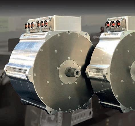


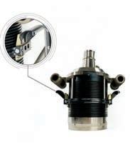
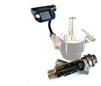


58 www.racecar-engineering.com Heralding a new era: Axial Flux Motors by Phi-Power 1040 Nm peak 170 kW nominal 9000 rpm 59 kg PHI302 MK II Phi-Power AG Fabrikstrasse 2 8330 Pfäffikon ZH Switzerland +41 (0) 44 555 89 67 info@phi-power.com www.phi-power.com From Racing Innovation to OEM Production 520 Nm peak 85 kW nominal 9000 rpm 30.5 kg PHI301 MK II
On the button
Designed to replace the success ballast previously

used in the BTCC, the new Cosworth hybrid package offers a unique solution to hybridisation

 By Stewart Mitchell


At the end of 2019, a tender was awarded to Cosworth by the TOCA-organised British Touring Car Championship (BTCC) to develop a hybrid system for the series.


By the middle of 2020, some testing of the system had begun, but Cosworth first had to understand how to build its system alongside the prescribed turbocharged, inline, four-cylinder ICE.
Rob Morrow, now at Delta-Cosworth, was initially project leader but handed over the reins in mid-2021 to Richard Woodgate, lead applications engineer at Cosworth, who was put in charge of the hybrid system and integration of it with the Cosworth 12V
electronics. Based in Cambridge, UK, his role is purely working on the BTCC project.
Design philosophy
TOCA’s target for the hybrid drive was 15 seconds of deployment per lap when the system is available. This should translate to that car gaining 15m within those 15 seconds, assuming a corner exit speed of 100km/h. The organising body didn’t want it to act like DRS, only being deployed in some regions of the circuit and only rewarding chasing drivers, as it believes this overtaking is too fabricated. Instead, it wanted a push-to-pass system racers can use at the exit of a corner to try and bring them alongside opponents in the next corner.
59
Photos: Francis Bradfi eld, Cosworth unless stated
BTCC | COSWORTH HYBRID PACKAGE
However, the driver in front would also be able to system to defend that position, keeping the racing close.
Cost was a significant consideration for the system. TOCA placed a lease cost limit on what the tender winner could charge. It was therefore evident a custom design would not be appropriate because the cost would have run out of control.
‘The motor, inverter and ancillaries needed to be mostly off-the-shelf components for cost reasons,’ confirms Woodgate. ‘The only component that sits outside of that is the battery, which has been designed uniquely for the BTCC application by Delta-Cosworth.
‘Because this is a hybrid system, and it isn’t the primary drive for the vehicle, peak efficiency isn’t the main driver for the specification. We needed a system that can deliver the required lap deployment duty, and only push enough energy back to the battery so we can recover a portion of that.


‘So, the considerations are slightly different compared to what other hybrid and electric race series demand.
‘We have managed to use a couple of suppliers and produce a safe, cost-effective system that meets all the targets.’
System specification
‘Cosworth hybrid package’ is the official name given to the system developed by Cosworth. It is based on TOCA’s requirement for low voltage (sub 60V) and, uniquely for a motorsport hybrid system, is designed to replace the BTCC’s success ballast concept, allowing it to be a racing tool rather than just a marketing gimmick.
‘BTCC is famous for its overtaking, and TOCA didn’t want to lose that,’ highlights Woodgate. ‘Also, TOCA chose a low voltage operation for ease of use. It means they (teams, marshals and event organisers) don’t have to go through high voltage training, acquire specialist equipment and so on.’
BTCC | COSWORTH HYBRID PACKAGE 60
The 1.7kWh total capacity Delta-Cosworth battery
Anything below 60V is classed as low voltage, and the Cosworth BTCC hybrid system’s peak voltage is around 56.5-57V from the battery. Running range is between 43 and 57V, with a nominal average about 51V.


The motor is an Emrax 188 – an axial flux, external permanent magnet rotor unit. In terms of control, three phases were deemed sufficient for the application on cost grounds.
‘Obviously, six phases would be great as then you can share your current across more phases, but we were limited by what we could buy off the shelf,’ explains Woodgate.
The motor weighs just 7.3kg and produces 30kW of continuous power and a maximum 50Nm of continuous torque, with a peak of 90Nm. It’s relatively small, too, being 188mm in diameter and 77mm deep.
61
Above: the heart of the system is an EMRAX 188 external rotor, permanent magnet, three-phase electric motor
Left: the Sevcon Gen4 MOSFET-based inverter
BTCC Cosworth hybrid package components laid out
In other words, ‘an ideal package as an offthe-shelf solution,’ as Woodgate describes it.
The axial flux architecture was chosen for speed matching alongside the ICE as the motor is mounted in parallel to the gearbox, driven off its input shaft. As such, it had to be rpm matched to the engine, and uses what is known as P2 parallel off-axis hybrid architecture, a highly flexible way of facilitating parallel hybridisation.
More specifically, TOCA and Cosworth decided to build the BTCC hybrid unit in a P2 off-axis drive module configuration at a 1:1 ratio, which sees the electric motor drive parallel to the crankshaft axis for a more compact axial package. This minimises the changes necessary to implement it with the existing internal combustion engine and transmission. The design offers compatibility with the series’ racing transmission, and addresses the tight packaging requirements of the BTCC drivetrain.
‘When the tender process went out, we looked at all the available packaging on the gearbox,’ says Woodgate. ‘We chose this solution in terms of power for the voltage range, and its power output is suitable for the speed range. So that was the key winning combination of factors.
‘This axial machine bolts through the centre, and the rotor spinning around
the outside gives us a higher torque delivery for the size. That was our main reason for choosing it.’
The continuous power figure of 30kW is achieved most efficiently at 4500rpm, but it can run up to a maximum of 8000rpm for a few seconds with the magnetic field weakening. Being direct drive with the ICE, the electric drive will spin at engine rpm, which, for 95 per cent of a BTCC car’s on-track life, is between 4000 and 7000rpm.
‘Under deployment, we adhere to our current limit of 650 amps, so we’re creating a power limit based on that,’ says Woodgate. ‘We’re normally around 25kW output, which equates to about 43 to 35Nm of torque through that speed range.’
The motor controller is a Sevcon unit supplied by Voltsport, which also performs the calibration of the system.
‘It’s not Formula E performance levels, but it’s quite efficient,’ notes Woodgate. ‘We see 96 per cent efficiency out of it. We couldn’t find anything in the price bracket that will do a better job, so we are happy with it.

‘The Sevcon unit controls the motor directly and is a slave to the Cosworth Antares 8 vehicle control unit [VCU], which runs all systems onboard the car. The Antares 8 VCU controls all the torque demand to and from the hybrid system, and the Sevcon unit
delivers what we need to or from the motor, and manages the switching accordingly.’
The switchgear inside the Sevcon part is simple but effective MOSFET technology, with a switching frequency of 12kHz, specified based on the BTCC duty cycle.
Battery technology
The battery design is based on automotive systems, and the BMS software carries a standard automotive safety layer. The battery has been developed around high voltage principles and contains all the necessary interlocked connectors and a manual service disconnect so engineers or marshals can isolate it quickly and easily.
BTCC | COSWORTH HYBRID PACKAGE 62
The British Touring Car Championship adopted hybridisation in 2022, becoming the first Touring Car championship worldwide to do so. At season end, it has been deemed a success
»
The axial flux architecture was chosen for speed matching alongside the ICE as the motor is mounted in parallel to the gearbox, driven off its input shaft
The BMS also carries out isolation monitoring and automotive standard safety protocol while in use.
‘We’ve kept the high voltage systems for this battery because if BTCC wanted to go to a higher voltage in the future, people will already be familiar with a certain level of safety involved,’ highlights Woodgate. ‘So, it’s trying to futureproof it a little bit.’
Cosworth chose the capacity based on the drive cycle TOCA proposed. That battery contains 14 cells in one string and produces 1.5kWh useable capacity and 1.7kWh total capacity. Safety standards drive the battery’s dimensions and location. There’s an unoccupied volume inside it so, if there’s an impact, there’s a built-in amount of deformation before anything is affected.
Although the battery architecture is quite conservative, it uses a lot of the knowledge Delta-Cosworth has amassed from developing electric powertrain for both the automotive world and bespoke high-performance racing machines. The cell sourced, and their packaging, are all designed
to make the liquid cooling system as compact and light as possible, as well as meeting the strict BTCC cost target.
‘The battery is a massive credit to the Delta-Cosworth team because racing batteries are a difficult thing to design, manufacture and make reliable,’ says Woodgate.
Like much of the rest of the system, the BMS is an off-the-shelf product too, and communicates directly with the Antares 8 onboard. It reads individual cell temperatures and voltages, and implements derating, should it be necessary.
‘We have a private network in the car, which is for the battery inverter and the Antares 8, and has several CAN outputs,’ explains Woodgate. ‘So, we use one solely for the hybrid system.’
On track, deployment is around the 450A mark. ‘It’s a lot because we are a low voltage system,’ notes Woodgate. ‘This system could produce the same amount of power at a higher voltage and be much smaller, and probably quite a bit lighter, too. But when cost is key, keeping design limits in place is important.’
In terms of battery longevity, Cosworth calculates there will be three seasons before they see a drop off in cell performance. Batteries are returned at the end of a season to be tested and validated against original profiles, to ensure any drop off is within acceptable limits.
‘We’d like to stick to that if we can, because we don’t want to be replacing cells often,’ says Woodgate. ‘Across 30 cars, that’s a big task. The system’s longevity and reliability are essential when it comes to one-make series. Teams need to be able to look after these cars and get the same performance each time they press the button.’
To stop the various electronic control systems meddling with each other’s signals, electromagnetic interference (EMI) shielding also needed to be considered.
‘Shielding is something we’ve had to design into our wiring looms to try and protect against EMI as best we can,’ says Woodgate. ‘EMI is a very complicated subject that normally an automotive manufacturer would spend a huge amount of money on, placing components in specialist chambers and having it measured. We don’t have the access, or budget, to do that. So we’ve just had to, from the outset, add insulation on our chassis harnesses and screening on all our analogue inputs and CAN networks.
‘We’ve taken a bit of a belt and braces approach to try and minimise our noise interference into the 12V system because that’s where data is extracted from. We don’t want that to be covered in EMI. And so, careful consideration of grounding, trying to make sure we don’t have any ground loop issues has been a big part of the programme.’
Regarding the configuration of sensors and telemetry, the BTCC limits what the teams are allowed to take off the car. The onboard sensor arrays are the standard set of racecar inputs you’d expect – dampers, steering, speed sensors and so on. There’s also an inertial motion unit on the car measuring g force in three axes. The ICE also has its sensor suite, with all required measurements of temperature, pressure and flow rates, while inside the battery is an independently designed onboard temperature monitoring unit run by the BMS – although no telemetry access to the BMS is allowed.
Slave operation
The hybrid system runs in what is known as a slave operation. ‘It’s not using its onboard VCU,’ explains Woodgate. ‘We do all the vehicle control within our Antares 8 ECU. This means we can manage what the system will do more accurately and then pass torque demand across to the inverter. We knew that we didn’t need to have all that processing power onboard the hybrid unit, we just needed a product that was going to be reliable, easy to fit and cost-effective.’
Ease of use was critical for the BTCC project too, and the last eight months of testing have been dedicated to that.
‘There were a lot of procedural elements that needed to be captured and covered so teams didn’t have to worry about that,’ confirms Woodgate. ‘It needed to be that the car looks after itself and all the teams have to do is just switch it on.
‘BTCC has been on an electronic suite for the last 10 years, and the cars have been brilliantly reliable. Teams have become used to that, and they expected that in 2022. We knew it would be difficult with a completely

63
Daniel Osei, control systems engineer at Delta-Cosworth, working on the BTCC hybrid system
» ‘We see 96 per cent efficiency out of it. We couldn’t find anything in the price bracket that will do a better job, so we are happy with it’
Richard Woodgate, lead applications engineer at Cosworth
new generation of cars, and a completely new generation of electronics. We knew teams would have a steep learning curve getting to grips with new 12V systems, let alone having a hybrid system off the side of it. For this reason, we made the system standalone, so it looks after itself as far as possible.’

Safety by design
Some of the design for ease of use includes procedural elements, such as being unable to switch the car on and start the engine before the hybrid battery has closed its contactors. Because the motor unit is directly driven from the gearbox input shaft and uses a permanent magnet, as soon as the engine is started, it starts generating energy. If that happens before the battery contacts are closed, the inverter knows this is a problem and will go into fault mode immediately.
In terms of calibration of the hybrid machine and inverter, an independent supplier takes care of that so, again, it is a ‘fit and forget’ situation. The calibration of the inverter, which Voltsport carries out, is quite conservative regarding how the deployment and recovery demand is tuned. This is so it doesn’t run into system limiting factors, whether thermal, speed or load.
The Cosworth Antares 8 control unit is ultimately in charge of the torque demand, as Woodgate explains: ‘We’ve created our torque generation maps based on pedal demand, speed of the motor and the current limit of the battery. We also know there are some other physical limitations, such as we can’t surpass 650A DC. And then, if the battery temperature increases and current becomes a limitation, we start to adhere to that. We can back calculate our power into torque, and that’s how we’re sticking to a limitation.
‘Ultimately, we’re asking the maximum we can achieve from the system when we deploy, but there’s a bit of safety margin in there.’
In terms of that margin, the BTCC hybrids have been achieving the proposed 15m advantage over 15 seconds of deployment at 25kW. That’s ideal for Cosworth as it means the system has a little headroom, and the losses caused by standard switching, and the mechanical losses from the electric machine into the system, are a little bit less. This has

the knock-on effect of not pumping quite as much heat into the cooling system, and consequently the system operates more consistently throughout the race, even as things heat up.
‘Being conservative for a spec system is always safer because we need to be able to achieve the reliability expected here,’ highlights Woodgate. ‘We’re still making the right amount of power to achieve the target advantage. This also means we could calibrate this system for higher output, should the rulebook want to, for example, go for a longer hybrid on-time per lap, or increase the torque output.
‘At the minute, deployment makes for roughly 20 per cent hybrid system duty per lap it deploys. If we started to push that
any further, we’d have to reconsider our regeneration balance, which is currently set at 12 per cent duty over a lap.’
Strategy element
The system’s regeneration is designed this way so an element of strategy is required for all the teams with hybrid deployment capability. Towards the end of the race, drivers will run down the battery’s state of charge (SOC) so, even for teams who have the full 15 seconds per lap deployment for the race, by the time they reach the chequered flag, they will be starting to run low on SOC. Those with fewer deployment laps must decide whether they choose to deploy early or later in the race, making sure they maximise their available deployment.
BTCC | COSWORTH HYBRID PACKAGE 64
The 23kg Delta-Cosworth battery pack is positioned alongside the driver, with all the regular safety protocols adhered to
The three-phase electric motor is mounted in the P2 off-axis configuration inside all entries in the BTCC
»
‘It needed to be that the car looks after itself and all the teams have to do is just switch it on’
Richard Woodgate
‘Strategy has been lacking in BTCC in previous years because, generally, all the cars have been so competitive. It has just been all-out racing,’ says Woodgate. ‘That’s good because it’s what makes the spectacle, and the new cars haven’t changed. It’s just they’ve got this addition now with the hybrid. How drivers and teams decide to use it on top of the already exciting racing adds another dimension.


‘Most drivers and teams are now starting to realise when is the best time to use the torque available. On some circuits, it seems obvious, but on others it is still a challenge.
Some teams have employed people to help them make the most of it, and others have to learn it race to race.
‘Additionally, TOCA does a good job of keeping the parity between the internal combustion engines so close that it is obvious when drivers use the hybrid.’
During a race, the status of the hybrid system is indicated to the driver on the Cosworth display in the cockpit. LED light panels in the side windows are used to display hybrid activation to fans, but currently have no diagnostic feature for the system
‘The choices the BTCC made in terms of data access goes back to having to make the car a very solid, user-friendly machine,’ explains Woodgate. ‘Because nobody in the pit lane can see the car’s status, it needs to flag any issues and then shout the message at the driver.’
Driver input
‘With the hybrid system on board now as well, drivers have a lot of new responsibilities, including handling the SOC of the battery, deployment and managing its usage across a lap, and the number of laps they can use it. The Cosworth display shows everything on the screen in front of them, but they have a job on their hands now.’
When it comes to using the hybrid deployment, there is a specific window within
which it can be deployed, and Cosworth has tried to make it as simple as possible. The driver must meet certain criteria, including throttle position, speed and gear before using the electric drive. Once they’ve achieved that, all they do is push a button.
‘Teams are allowed to build their alarms, messaging, lights or whatever they want to indicate to the driver that they can deploy,’ notes Woodgate. ‘A lot of them have gone with a status LED that, when lit, means the driver can deploy. However, also managed in the software is a penalty system. If the driver presses the deployment button below one of those criteria, it adds a delay before deployment engages. That is to prevent drivers sitting on the button and letting the system come on automatically when all those criteria are met, taking out the driver element.’
What the system does take care of automatically is the 12 per cent regeneration per lap. TOCA didn’t want teams to be able to calibrate or adjust that. Regeneration occurs off throttle above a specific rpm and below a certain amount of throttle. Part of the calibration of regeneration was to ensure the car’s deceleration felt natural.
‘Our biggest concern was rear-wheel drive regeneration because, obviously, the characteristic for the front-wheel-drive is that we could probably put more torque across the front axle and not affect braking at all,’ says Woodgate. ‘But with rear-wheel drive, where weight transfer takes place, the driven axle gets lighter.
‘The fact is, we can generate a maximum of about 20Nm of torque under braking with both in its current configuration if we need it. We could increase it to 35 or 40Nm of brake torque and start to pull back nearly double in terms of power with this system, but this first season is set out already, and again we are being conservative.
‘Most drivers have said, with the system off or on, they can’t feel the regenerative braking input at the wheel.’
A small amount of contact is always expected within the very close racing environment of the BTCC, and this formed part of the development process.
‘Crashing was one of our biggest reliability concerns, having two radiators in the front bumper,’ says Woodgate. ‘Front bumper real estate is hard to come by with a turbocharged ICE with an intercooler and radiator already. So all the available frontal area is used for that. Our coolers are a lot smaller and are fitted under the subframe on the corner extremities.
‘Sadly, there’s not a lot you can do if, or when, an on-track incident takes place. You’ll probably be okay if it’s one lap from the end of the race. If it isn’t, then a driver will probably have to come in. That’s just a factor of racing in the BTCC.’ l
65
»
‘With the hybrid system on board now as well, drivers have a lot of new responsibilities, including handling the SOC of the battery, deployment and managing its usage across a lap’
Richard Woodgate
A flashing blue lightning bolt illuminated in the window shows fans and spectators when the hybrid system is being used
BTCC
Efficiency drive
With the growth in EV racing, the quest to improve efficiency in electric motors has gained pace in recent years, with new technologies and wonder materials emerging. Racecar assesses their impact
By Lawrence Butcher
Electric motorsport, probably more than any other genre of racing, is all about incremental gains, particularly in terms of powertrain development.
Take Formula E, where, even in its first season of competition, the efficiency of the spec, McLaren-supplied motor and inverter package was around 96 per cent. A fair figure today would likely be somewhere between 98 and 99 per cent.
But however small the improvements, across the board – be it in WEC, F1 or FE –manufacturers have been chasing electrical efficiency gains from motors, inverters and battery systems. It is the first of these that we will focus on here.
An electric powertrain must be considered in terms of the motor and controller when thinking of efficiency (and, where used, the transmission). Each element is closely linked, and gains made in one area can easily be cancelled out if another part of the chain has excessive losses. Similarly, it is impossible
to create a highly efficient motor without a suitably capable control system (just as an F1 engine would be useless without its ECUs).
To briefly recap the types of motor most found in racing applications, at one end of the scale are the very high output, but relatively crude, DC units, like those found in electric drag cars. These have excellent power characteristics but are hard to control and not suitable for applications that require energy recovery. Advanced hybrid and electric race vehicles tend to use AC (alternating
current) motors and, amongst the various subsets of AC motors, synchronous motors are currently seen as the best solution. In most applications, this means the use of permanent magnet synchronous motors (PMSMs), of either the axial or radial flux type.
The majority of PMSMs utilise permanent magnets mounted on the surface of the rotor. This makes the motor appear magnetically ‘round’, and the motor torque is the result of the reactive force between the magnets on the rotor and the electromagnets of the stator. However, some PMSMs have magnets buried inside the rotor structure, referred to as Interior Permanent Magnet (IPM) motors.
Electrical losses
Common to ICE and electric machines are mechanical losses, though obviously they are far less significant in an electric motor. But whereas in an ICE there are losses in the combustion system, in a motor there are electrical losses to contend with.
Thin laminations
a
that is able to flow. Some of these laminations can be incredibly thin, 0.127mm thickness for example,

ELECTRIC MOTORS | EFFICIENCY 66
Brandauer
create
smaller conduction path for the currents than thicker laminations. With current proportional to the area of the loop, reducing the area reduces the current
and they are rolled from non-grain-orientated electrical steels (NGOES)
» Both ICE and electric motor losses tend to manifest themselves as heat
The arrangement of the copper windings is key to the performance of the electromagnet, as the pattern determines the direction of the electromagnetic field

67
An axial flux e-motor with an integrated inverter unit. In this type of electric motor, the gap between the rotor and stator, or rather the flux between the two, is parallel to the axis of rotation

Furthermore, both ICE and electric motor losses tend to manifest themselves as heat, which must be managed, a subject which we will be returning to later.
Motor losses can be broken down into iron or core losses, and copper or ohmic losses, each with its own set of characteristics, both of which contribute to a reduction in efficiency. Typically, many of the phenomena that cause losses also increase in severity when one ups the power of a motor.

Iron losses
Starting with iron losses, normally shown as W/kg, these are comprised of eddy currents and hysteresis. Eddy currents, as their name suggests, are currents that swirl like eddies in a stream. They run perpendicular to the magnetic field of a stationary conductor (in this case the stator) and are induced by changing magnetic fields in a closed loop, according to Lenz’s law.
The problem is that as motor speed increases, so too do eddy current losses, which are proportional to the square of the electrical frequency of the motor. With the trend towards ever faster and more compact
ELECTRIC MOTORS | EFFICIENCY 68
»
Each element of an electric powertrain is closely linked and gains made in one area can easily be cancelled out if another part of the chain has excessive losses
Equipmake
Nearly every contemporary high-performance electric motor employs very thin steel lamination that forms the stator stack. These are separated by an insulation layer, which needs to be kept to a minimum, while still allowing thermal conductivity
Laser Masters
motors, iron losses are a major consideration for electric motor designers.

One of the main routes to reducing eddy current losses in the stator is through a combination of materials engineering and construction. Nearly every, but not all, contemporary high-performance motor features very thin steel laminations that form the stator stack, each separated by an insulation layer. Thin laminations create a smaller conduction path for the currents than if thicker laminations are employed.
With current being proportional to the area of the loop, reducing the area reduces the current that can flow. And as losses are proportional to the square of the current, even relatively small drops in current can net useful gains in efficiency.
In the past, a thin lamination was considered to be in the region of 0.5mm, but advances in manufacturing techniques have seen much thinner laminations become available. For example, Arnold Magnetics produces its Arnon 5 and 7 laminations at 0.127mm and 0.178mm respectively. These are rolled from non-grain-orientated electrical steels (NGOES), which are ideal for motor use.
The company can also supply grainorientated electrical steels, more commonly used in transformers (which have different magnetic requirements) down to 0.025mm thickness. To put this into perspective, the Formula 1 regulations limit laminate to a minimum of 0.05mm in the MGU-K, though the MGU-H is not limited. According to Arnold Magnetics, a switch from a traditional 29 gauge (0.34mm) laminate to a 0.127mm production, can net in excess of a 60 per cent reduction in iron losses.
One issue with using exceptionally thin laminations is that the thinner the sheet, the harder it is to reliably stamp out the stator laminates. Factor in the ever-increasing complexity of stator design, coupled with the challenges of reliably joining – either mechanically or via bonding – the individual laminations together, and it is clear why the very thinnest materials are the preserve of high-value, low-volume motors where ultimate efficiency is required.
Another means of reducing eddy currents in the stator is to use high-resistivity steels, which will tend to be referred to as silicon or electrical steels and have low hysteresis.
It used to be that these steels had the disadvantage of a low saturation flux density. In practice, this means a large and heavy stator was needed to achieve the same magnetic field as a material with a higher saturation flux density. But again, the past decade has seen new materials arrive on the market that have both high resistivity and good flux density.
Ultimate power density
Moving up another step, for ultimate power density, high-induction, low-loss cobalt alloys are favoured. For example, German firm, Vacuumschmelze, has long supplied its Vacoflux and Vacodur, 49 per cent cobalt-iron alloys into high-end racing. With exceptionally high saturation polarisation of 2.3T, they far outperform even the best silicon-steels, albeit at high cost.
To make such alloys more accessible, the company released its Vacoflux X1 in 2019, with a 17 per cent cobalt content. It claims that, compared to a motor using grade 20 NGOES, torque output can be increased by up to 12.5 per cent at a cost closer to electrical steel than the 49 per cent cobalt alloys.
69
Equipmake
The permanent magnet radial flux motor is the choice for many motorsport applications. This APM 120R is an interior permanent magnet motor with samarium cobalt magnets
Moving away from laminations, one of the latest developments in terms of stator materials are soft magnetic composites (SMCs), which have the potential to replace steel laminations in many motor applications. The great advantage of these is they have isotropic magnetic properties that allow for more complex magnetic design concepts than are possible with steel laminates, which have 2D magnetic properties.
SMCs are created using magnetic powder with an electrically resistive coating, which can be formed into complex 3D shapes using conventional powder metallurgy techniques. In addition to facilitating advanced magnetic designs, the insulating coating of the powder grains contains eddy currents within each grain of material, greatly reducing core losses at high frequencies (SMCs come into their own above 400Hz).
There are some challenges when it comes to processing these materials, though. For example, finished parts must be heat treated to remove micro stresses after the compaction process. However, because the insulation material degrades at a lower temperature than the base powder, iron, anneals at, it is hard to fully remove all stresses.
Hysteresis losses
All of the materials listed above also help reduce hysteresis losses. These are caused by the magnetisation and demagnetisation process within a motor core as current flow changes direction. As the magnetising force (current) increases, so too does the magnetic flux. However, as the magnetising force (current) decreases, the magnetic flux doesn’t decrease at the same rate, but less gradually. Therefore, when the magnetising force reaches zero, the flux density still has a positive value. In order for the flux density to reach zero, the magnetising force must be applied in the negative direction.
The relationship between the magnetising force and the flux density are represented on a hysteresis curve, or loop. The area of the hysteresis loop (rather like the area under the curve for an engine) shows the energy required to complete a full cycle of magnetising and de-magnetising. The greater the area of the loop, the higher the losses. So-called ‘soft’ magnetic materials, such as those detailed, are said to have a small area hysteresis loop.
It is worth noting that it is not only the magnetic material in the stator core that must be considered. The insulation between the individual laminations also needs to be kept to a minimum, while ensuring proper insulation is provided, and also allowing for thermal conductivity.
One favoured material for stator insulation is Nomex. While better known in racing for its use in fireproof equipment and
honeycomb material for composites, Nomex paper is a widely used insulator. According to its manufacturer, DuPont, 80 per cent of BEVs utilise it in their traction motors, with the highest performance commercially available grade being Nomex 464 Lam, a lightweight, flexible paper insulation that can be supplied down to 0.05mm thickness.
DuPont is in fact a partner of the Alpine Renault F1 team, and Carlo Fiorella, the company’s global automotive manager, says that it uses Formula 1 as a test bed for its insulation materials, helping make them lighter, stronger and with better thermal conductivity. Taking this last factor, generally speaking, thermal conductivity and electrical insulation tend to work against each other. So how can these seemingly mutually exclusive properties be combined?
This edges toward the territory of confidential IP, but Fiorella was prepared to say: ‘We have materials that do enable high insulation with good thermal conductivity. Some of those are newer next-generation ones that are still in development, but it is a great area of research. We are always looking for ways to increase the thermal performance without decreasing safety.’

Copper losses
Copper, or ohmic, losses occur predominantly within the stator windings of a PMSM, and can be broadly split into frequency dependent and frequency independent losses. These occur on the basis of I2R, where losses in Watts are equal to the current squared times the resistance of the wire. The key to lowering these is reducing the resistance in the winding wires.
Frequency-independent losses relate to the cross-sectional area, length and material of the stator windings, as well as their temperature. Pivotal to reducing the resistance of the windings for a given motor size (and increasing its torque density) is maximising the fill factor. This is the reason why most traction motors now rely on hairpin windings, where rectangular rather than round wire is used.
There are a host of other developments related to stator fill currently underway. For example, additive manufactured windings that can be created in forms impossible to achieve by regular winding processes.
Meanwhile, frequency-dependent losses revolve around a phenomenon called skin effect, whereby the effective diameter of a wire is reduced as the frequency of an alternating current increases. As the frequency goes up, the current flow moves to the surface of a wire, increasing the resistance
ELECTRIC MOTORS | EFFICIENCY 70
»
‘We have materials that do enable high insulation with good thermal conductivity. Some of those are newer nextgeneration ones that are still in development’
Carlo Fiorella, global automotive manager at DuPont
Equipmake
Efficiency map of an interior permanent magnet motor. With these, the magnets are positioned inside the rotor structure
Changing the shape of the stator slots affects the magnetic path around them. This lamination steel is for the 200 to 2500Hz frequency range
and therefore temperature, which in turns increases resistance further.
The solution is to use smaller diameter wires, but this is only effective up to a point. The creation of eddy currents in wires adjacent to one another alters the distribution of current flowing through each wire, concentrating the current in areas of the conductor furthest away from adjacent wires with current flowing in the same direction. This is known as the proximity effect, and can have a significant impact on resistance. It is a careful balancing act to find the best ratio of conductor thickness and distribution.
In addition to good electrical design, effective cooling is vital to reducing copper losses in a motor. Most motors in a motorsport context will feature liquid cooling of one form or another, either direct cooling of the stator using dielectric fluid or, more
commonly, the use of a cooling jacket around the stator, which interfaces using a cold plate.
Effective cooling
With the latter approach, one of the most important elements to consider is the interface between the stator and the cold plate. Maximising the thermal conductivity in this area is what produces efficient cooling. For example, if the contact between the windings and the plate is poor, or the cooling efficiency between the windings and the stator core is reduced, losses will increase. Therefore, elements such as the surface flatness of both the core and the cooling plates have a greater impact on cooling than the coolant flow within the cold plate.
The insulation material that encases the stator windings also plays an important role in cooling efficiency, with many motors using
an insulating varnish. This has been an area of considerable development in recent years and single, double and triple-coated wires are available. Triple-coated wires are supposed to eliminate any pinholes in the insulation, which increases resistance to corona discharge (ionisation of air surrounding the wire). However, the thicker the coating, the lower the thermal conductivity, hence the development of varnishes that can be applied in a thin, pinhole-free coat and provide good corona resistance with high thermal conductivity.

Additionally, the thicker the insulation, the less space there is for wire, reducing fill factor, so the higher the resistance for a given current and the greater the temperate increase under load.
It’s worth noting that there are also some circumstances where absolutely maximising
71
» One of the most important elements to consider is the interface between the stator and the cold plate
Tata Steel
In YASA’s yokeless axial flux motor the flux jumps from the stator tooth to the magnets and back to the next stator tooth. Advantages of this design are the ability to have the flux interact with the two sets of magnets, significantly increasing the power density of the design – meaning less weight, less current, fewer losses and more power

fill factor may not be the route to optimum efficiency. For example, a particular stator design may be very good for cooling, but at the expense of copper fill, though the latter is cancelled out by the reduction in losses the additional cooling provides.
Complex matters
This article gives an introduction to some of the factors that drive motor efficiency, but there are a whole host of other mechanisms at work that create losses.
For example, PMSMs inherently suffer from a high level of ‘back’ EMF (electro motive force), a side effect of a magnet spinning within a stator. With a permanent magnet, the back EMF is proportional to motor speed so, once a motor reaches a certain speed, the back EMF will cancel out the available
motor supply voltage, effectively limiting the maximum speed of a motor. This can be countered by ‘field weakening’ the motor, a process that injects extra currents into the winding, reducing the magnetic flux of the rotor magnets. Using this technique, motor speeds can be increased by a factor of five.
The use of different winding designs can also decrease back EMF, with distributed (where the windings are distributed across the air gap of the motor) generally proving more efficient than concentrated windings (where each winding only goes around a single slot in the motor). As always, there is a ‘however’, and in this case it is that well designed concentrated windings can also have low back EMF.
Then there are losses related to the rotor’s magnetic design, and even the sleeve used
to constrain the magnets on an PMSM. For example, if the sleeve is conductive, this creates a distortion in the magnetic flux and causes eddy currents. The use of a nonconductive sleeve removes these losses, but there is a caveat here too, of course. If, for example, an Inconel sleeve is used, overall rotor losses can actually be lower due to it shielding the rotor. To achieve a similar level of performance with a non-conductive sleeve requires the use of laminated magnets, which have lower losses at the cost of a small amount of torque output.
Summing up, then, it would be fair to say that the exceptional performance and efficiency of current machines is down to a complex combination of innovative thinking, materials development and advances in modelling capabilities. l
ELECTRIC MOTORS | EFFICIENCY 72
Motors
YASA
Experience the advantage of outstanding performance.


The engineers of the world’s best performing electric motors have evolved. Helix now makes ultimate power density accessible through scalable core technology and volume production facilities. On the road and track, at sea, in the air and in a multitude of industrial applications, Helix electric power is the future.

Find out more at ehelix.com

Sustainable thinking


Racecar talks

to Johann Wacht of Bcomp to find out how technology transfer from motorsport can play an important role in preserving the future of our planet


 By Gemma Hatton
If there was anything good to come from the Covid-19 pandemic, it was how quickly the planet began to recover without the normal levels of human activity. While we were locked in our homes, skies became clearer, waterways less polluted and wildlife returned to local areas.
Within a few months of lockdowns, people in the northern Indian state of Punjab could see the Himalayas from more than 100 miles away for the first time in decades. The canals in Venice were blue, and mountain lions roamed the streets of Santiago.
Overall, the global CO2 emissions in 2020 dropped by 6.4 per cent, which equates to 2.3 billion tonnes of CO2 that didn’t enter the atmosphere. The quick recovery of Mother Nature provided hope during a very dark time, but it also bought into sharp focus the impact we have on our planet.


The good news is that since the ordeal of 2020, society has had a shift in mindset. More companies than ever are driving towards a more environmentally friendly future, which has opened the door for more sustainable technologies to be designed, developed and integrated into all industries, but specifically here the motorsport industry.
‘When we first entered motorsport, the regulators were mostly interested in the safety benefits of our natural fibre composites,’ explains Johann Wacht, manager of motorsports and supercars at Bcomp. ‘Unlike carbon, our materials don’t splinter, which reduces the risk of punctures.

‘But when the pandemic came and people were forced to stay at home with their families, their perspectives changed, and they became more concerned about the future and therefore sustainability. This meant people started to really understand

MATERIALS | NATURAL FIBRE COMPOSITES 74
A motorsports bodywork lay up with two layers of ampliTex reinforced on the b-side with powerRibs
Bcomp
»
The technical sweet spot of our natural fibre composites lies in stiffness. We can achieve the same stiffness and weight as an 830gsm monolithic carbon fibre lay up
Johann Wacht, manager of motorsports and supercars at Bcomp
the added value of our technology and that by integrating natural fibre composites into racecars, not only are you making them safer, you are making them more sustainable, too.’
Natural fibre composites


Bcomp has developed a natural fibre composite using flax fibres extracted from the stem of the Linum usitatissimum plant. These fibres are woven together to produce a flexible fabric called ampliTex, which is then impregnated with epoxy resin, similar to a ply of carbon fibre. Different weaving patterns such as bi-axial, twills and uni-directional can then be used to tailor the mechanical properties of the material to suit specific applications.
Flax fibres can also be twisted to form a thick yarn that can then be stitched together to create a grid, called powerRibs. To achieve high stiffness for minimal


weight, powerRibs can be bonded to the ampliTex fabric, providing reinforcement and forming a 3D structure on one side of a thin-walled shell element.
‘The technical sweet spot of our natural fibre composites lies in stiffness,’ says Wacht. ‘We can achieve the same stiffness and weight as an 830gsm [grams per square metre] monolithic carbon fibre lay up, making our materials perfect for any semi-structural part that is mainly loaded in bending.
‘But if you need high strength, or very high stiffness, then carbon fibre composites are superior.’
Consequently, Bcomp focuses primarily on thin-shelled parts, typically monolithic applications up to 1mm thick / 1000gsm carbon lay ups, such as racecar bodywork. This was first featured on the bodywork of the Four Motors Bioconcept cars, in

collaboration with Porsche Motorsport and Fraunhofer, and was so successful that natural fibre composites were quickly integrated into the bodywork of GT4, DTM and Extreme E cars.
Interior design
Another growing application of Bcomp’s product is automotive interior door panels and trim parts. This technique has been adopted by the likes of Polestar and Volvo in their concept cars over the last few years and, by the end of 2022, Bcomp will be supplying the first large scale automotive project in the interior sector.
However, it’s not just bodywork and interiors that natural fibre composites are now suitable for. This was proven with motorsport’s first natural fibre Front Impact Absorbing Structure (FIAS). This was designed and manufactured by Ycom for a
75 McLaren Racing Bcomp
AmpliTex reinforcement fabric (dry), showing the natural fibre its made from and two different weave patterns
» When we first entered motorsport, the regulators were mostly interested in the safety benefits of our natural fibre composites
Johann Wacht
McLaren racing seat with Bcomp ampliTex and powerRibs integrated into the structure
formula car and passed FIA crash safety standards in 2020. Although 27 per cent heavier than carbon fibre, the design offers an estimated 77 per cent reduction in material CO2 emissions, while the overall weight of the car increased by less than one per cent.

If this slight increase in weight is not an option, or the performance requirements are too challenging for a 100 per cent natural fibre lay up, ampliTex and powerRibs can be combined with carbon fibre skins. This approach was used for BMW’s iFE.20 Formula E car and the latest Super Formula Next50 cars, which still allowed a natural fibre use of 70 per cent whilst achieving high levels of performance.
Environmental impact
To fully understand the environmental impact of any part, product or material, the carbon footprint of the product’s entire life cycle must be calculated. This is known as a cradle-to-grave life cycle analysis, and considers every stage of a product’s life cycle, from extracting the natural resources from the ground, through manufacturing and product use, to final disposal.
However, it is extremely difficult for manufacturers to quantify the CO2 emissions once a product has been transported to a consumer, which is why the majority of companies conduct so-called cradleto-gate life cycle analyses instead. These consider the part of a product’s life cycle from extraction through to the product leaving the manufacturing factory.
To compare the carbon footprint of natural fibre composites with carbon fibre, Bcomp conducted a study that analysed the global warming potential (GWP) of the greenhouse gas emissions from cradle to gate.
GWP essentially measures how much heat energy one tonne of greenhouse gas will absorb in the atmosphere, relative to one tonne of CO2. In this way, the actual impact of a product’s life cycle emissions on the planet can be better estimated, rather than just looking at the total emissions. For example, methane has a GWP of 27-30 over 100 years so, if one tonne of methane is emitted to the atmosphere, it would have the same effect as emitting 27-30 tonnes of CO2.


‘Often the bodywork of GT cars consists of a lay up of carbon fibre that is approximately 830 gsm as this gives the required stiffness,’ explains Wacht. ‘Considering the GWP of the materials, processes and consumables, the carbon footprint of this type of carbon fibre is 49.4kg CO2 eq/m². Normalising the part size and stiffness, the carbon footprint for the equivalent amount of natural fibre composite using just ampliTex [polyethylene terephthalate] is 9.9 kg CO2 eq/m², although this material is slightly heavier than carbon.
‘But when we use ampliTex with powerRibs, this drops to 7kg CO2 eq/ m², whilst matching the stiffness and weight of carbon fibre. So, overall, our materials can reduce cradle-to-gate CO2 emissions by 80 to 85 per cent.’
MATERIALS | NATURAL FIBRE COMPOSITES 76
A-side of a bodywork section made with Bcomp ampliTex and powerRibs
Close up of one of the interior components of the Porsche 718 Cayman GT4 Clubsport MR made from Bcomp natural fibre materials
Porsche 718 Cayman GT4 Clubsport MR with natural-fibre composite exterior formed using ampliTex and powerRibs
» Overall, our materials can reduce cradle-togate CO2 emissions by 80 to 85 per cent
Johann Wacht
Carbon footprint of interior panels
Carbon footprint of composite lay ups Dr. Ing. h.c. F. Porsche AG Dr. Ing. h.c. F. Porsche AG Bcomp
The same analysis can be done for automotive interiors. Conventionally, manufacturers use thermoplastics such as Injection Moulded Polypropylene (IMPP), which has a carbon footprint of 6.4kg CO2 eq/m². Replacing this with Natural Fibre Polypropylene (NFPP) reduces this to 3.7kg CO2 eq/m². Combining NFPP with powerRibs drops this further to 2.3kg CO2 eq/m².
A natural fibre composite part with powerRibs can therefore achieve up to 50 per cent less weight, 70 per cent less plastic and 62 per cent lower CO2 emissions compared to standard IMPP interiors.
Carbon emissions
‘Ultimately, we need to reduce carbon emissions in any way we can, because every gain we make emits slightly less CO2 into the atmosphere and reduces the effects of climate change,’ concludes Wacht.
‘Of course, the ideal solution would be to achieve technologies that are 100 per cent sustainable but, if this is not possible right now, then why not aim for 70, 80 or 90 per cent? We often get challenged over the fact we still use epoxy resin, but our materials still reduce CO2 by up to 85 per cent on part level compared to carbon fibre, which is much better than nothing, until we find a fully sustainable alternative.
‘Natural fibre composites may not be applicable for Formula 1 crash structures yet, but that hasn’t stopped McLaren F1 integrating our materials into drivers’ seats and pit stands. So I think society needs to think in this way and minimise the environmental impact wherever we can, whilst continuing the momentum of developing sustainable technologies.’ l
The perfect platform
As concern about climate change gained momentum in 2018, there were question marks over the future of motorsport. After all, it encourages people to travel to circuits and watch cars race in circles that are prepared by teams who travel across the world – all for entertainment purposes. However, as has always been the case, racing provides the perfect platform to drive change. Just as manufacturers followed the ‘race on Sunday, buy on Monday’ model decades ago, the same applies for sustainable technologies today.

‘Motorsport has the power to test, develop, promote and scale sustainable technologies to a global audience,’ highlights Johann Wacht, manager of motorsports and supercars at Bcomp. ‘Often discussions about sustainability in motorsport revolve around the race event itself. Yet all the sustainability initiatives implemented at a racetrack can also be put in place at a football or NBA stadium. The trick with motorsport, though, is that the technology developed on racecars can be directly transferred to the automotive industry, and the cars we drive on a daily basis.

‘It’s this technology transfer to wider society that makes motorsport such a unique platform for developing and scaling sustainable technologies to maximise impact. And why it has such an important role to play in the planet’s future.’
It’s not just for show either. Here’s Four Motor’s Porsche 718 Cayman GT4 Clubsport MR in competition with its natural fibre composite panels using ampliTex and powerRibs
77
BMW M Motorsport
Four Motors
Manufacturers keen to stress their eco credentials are jumping on board. Here a BMW M GT4 with Bcomp bodywork
Black is the new green
Tyre manufacturers are looking to improve their sustainable credentials.
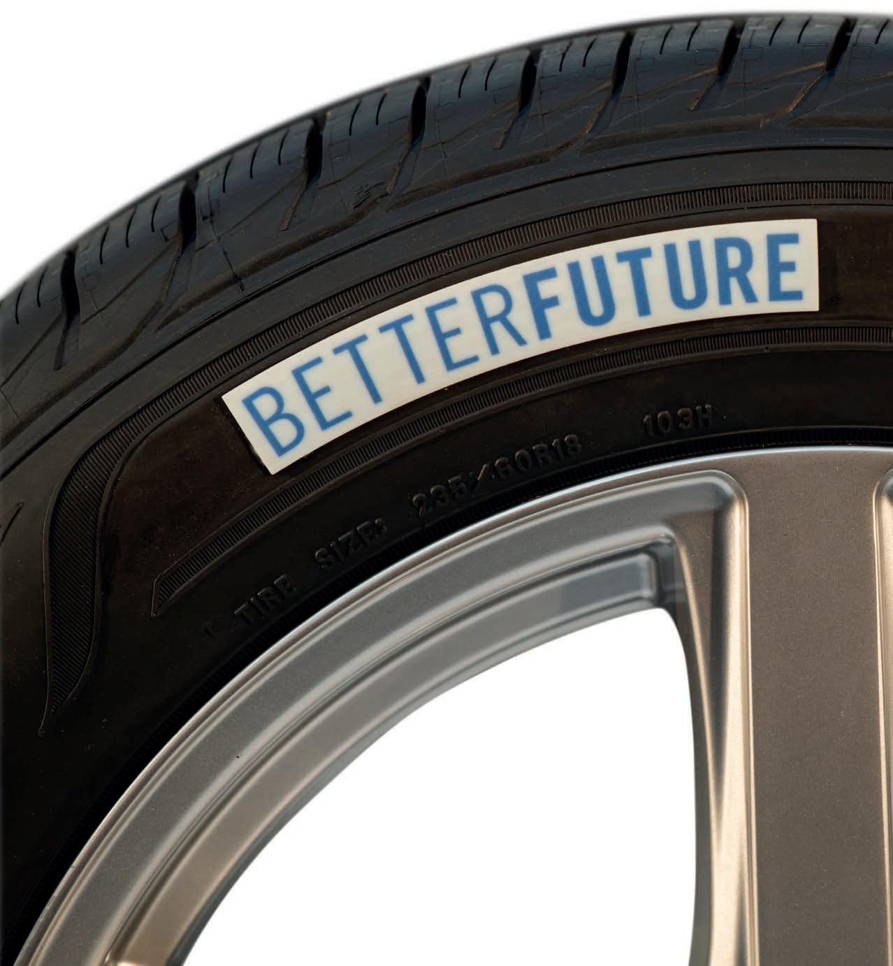 Racecar investigates
By Andrew Cotton
Racecar investigates
By Andrew Cotton
REDUCING WASTE | TYRES
On the face of it, there is very little that is environmentally friendly about racing tyres. They contain oil and rubber, are quick to degrade, last for less than 200km in Formula 1 conditions and, even in endurance racing, 700km on a set of tyres is considered an impressive achievement.
Yet, beneath the surface, the two suppliers to the FIA World Endurance Championship,
Michelin and Goodyear, are well aware of their environmental responsibilities, and are busy finding new ways of reducing their overall global impact.
They have both taken major steps in the last few years to limit waste. With the help of the FIA, although somewhat controversially and unpopular as the decision was, they have shared the categories between them to eliminate tyre competition. From 2021,
Michelin was awarded the Prototype and GTE Pro classes, Goodyear LMP2. Having removed the competition in terms of performance, the two manufacturers have instead been able to focus on sustainability and tyre technologies.
Each of the cars in the WEC runs on 18in rims, the number of specification wet and dry tyres have been reduced (voluntarily by the tyre manufacturers) and, with regulations that increase the time penalty for changing tyres
Tyre manufacturers have worked hard to reduce waste, both in the production and disposal of their products with an eye on passenger car application
» ‘You can make roads out of tyres… I love that idea, worn race tyres produce race tracks sounds cool, and we can do that’
Matthieu Bonardel, head of motorsport business at Michelin
compared to refuelling only, there is now a sporting incentive to run on the same set of tyres for a greater mileage.
By running similar specification tyres for multiple race series organised by the FIA and the ACO, both the tyre manufacturers have reduced waste in development.
Wider picture
The battle to reduce the environmental impact of racing tyres is as important to the manufacturers as outright performance and reliability. Michelin has the firm goal of producing tyres that do not need tyre warmers to heat the rubber up before they are fitted to the cars, for example, although that target seems to be moving further away than ever following resistance from teams. The intention behind it is to remove the need for tyre ovens in the paddock, although teams argue that it is more expensive to heat tyres on track, with the added risk of crashing.
Defining what is a sustainable tyre is not easy as there are so many elements to the process. The first and most obvious part is to look at tyre manufacturing itself, primarily by
using sustainable or recycled materials, rather than wasting natural resources. The second is to look at the energy required to create a tyre and make that process more efficient. The third is to look at tyre disposal, and putting the spent product to the best possible use.
However, the tyre companies are also looking further afield, considering the entire tyre manufacturing process from design and construction, through factory efficiencies to moving products to and from the race circuits, working with partners to reduce transport costs, as well as looking at the race series that are supplied.
Both Michelin and Goodyear have been, or are, involved in electric racing, which produces zero emissions at the tailpipe. Michelin was a founding partner of the Formula E project, the first single-seat electric series to be able to claim carbon zero status. That was a huge marketing bonanza for the French tyre company, which produced a single tyre that lasted for the season, in both wet and dry conditions. Goodyear is also involved in the FIA ETCR - e-Touring World Cup, now the only global Touring Car
series running on purely electric power. The series is still a long way behind the globally recognised Formula E in terms of grid numbers, support, finance and technology, but for Goodyear it’s an important series in which to be involved.
Different tyre companies have very different solutions to the whole issue of sustainability, which affects not only racing tyres but also, more pertinently, production car tyres. The two are closely linked – so what is good for one must be good for the other –
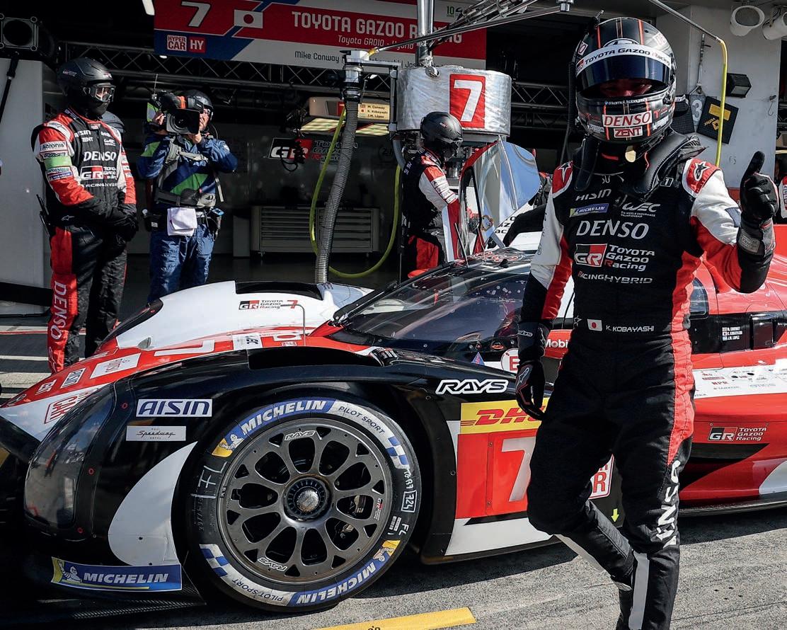
80 REDUCING WASTE | TYRES
It was a controversial move by the FIA to limit tyre suppliers in its classes to just Michelin and Goodyear but, in doing so, it dramatically reduced tyre waste in development and use
» The battle for sustainability is as important to the manufacturers as outright performance and reliability
XPB


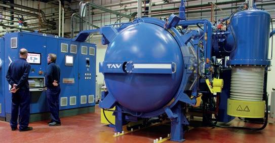
www.racecar-engineering.com 81 Member www.getecno.com Your demand, our efficiency PERMAGLIDE® Seals-it® ® RODOBAL ® ROD ENDS SPHERICAL BEARINGS BUSHING ACCESSORIES Broadest range in Europe! Untitled-22 1 22/04/2022 13:30 Materials processing of Motorsport components THT offer a consistent and reliable service of high quality processing with short lead-times to keep your production schedule on track. Vacuum processing of precision components and metal 3D printed builds along with Plasma nitride processing. All utilising the latest in vacuum atmosphere technology. Find out more: www.tamworth-heat.co.uk sales@tamworth-heat.co.uk +44 1827 318 030 Tamworth Heat Treatment Ltd 7 Darwell Park, Tamworth, Staffordshire. B77 4DR. United Kingdom
though experimental solutions are rather easier to put into reality in racing than in large volume production.
Different approach
When Formula 1 banned refuelling, it needed to find a way to force teams to pit, as a race without stopping had the danger of being processional. It hit on the idea of introducing a tyre that deliberately loses performance in a short space of time, leading to a faster race time on newer rubber. Sole tyre supplier, Pirelli, has different types of compound, which allow for more speed over a short space of time (soft compound) or less speed over a longer distance (hard compound). From an environmental standpoint, the public sees a high-degradation tyre that needs to be replaced after a short period of running, but the show is considered more important.
It's a different story in GT racing. Pirelli also supplies tyres to GT3 series around the world. Here, there is an immediate advantage in that the same product is used, on the same size 18in rim. This reduces development requirements (and waste from discarded ideas) as well as the overall number of tyres produced. The tyre now used on all GT3 cars lasts for around 65 minutes in normal running conditions, although teams have been known to double stint them on a low-degradation circuit.
In the World Endurance Championship, however, races last at least six hours, and tyre regulations are slightly different. The number of tyres per race is limited, which means teams are forced to at least double stint their tyres at one point during the race.
WEC regulations also ban tyre changes at the same time as refuelling, meaning time can be gained in the pit by not changing rubber. That leads to longer mileage on a single set, and it is the job of both Michelin and Goodyear to produce tyres that reduce drop in performance. Both companies are proud of the mileage their rubber is able to complete, and have plans to improve durability further still.
Intermediate action
‘The most sustainable tyre is the one you don’t produce,’ says Michelin’s head of motorsport business, Matthieu Bonardel. ‘We have longer stints, fewer tyres produced by event, and so on. [We want] less tyre specification, like we did in Formula E, and we have cut down on the wet options in the WEC. We got rid of the intermediate, and so our managing of all WEC tracks is only one wet spec. Reducing the number of wets is meaningful because we scrap a lot of wet tyres [at the end of the season] because it just doesn’t rain, yet you still have to be prepared for it. It was the same thing for slicks.’
Goodyear supports this view. ‘Until recently in LMP2, we still had three slicks, one intermediate and one wet,’ explains Roland Close, senior manager, OE and car motorsport at Goodyear. 'Next year [2023], we will have only one slick and one wet. We can reduce the total amount of tyres we bring because we don’t need to prepare for all eventualities. That means less transportation and maintenance, helping sustainability.
‘For the ETCR, we are the founding partner, so the first year of racing was in 2021 and this year it became an FIA World Cup. The tyre is suitable for wet and for dry, so this is also the mindset of sustainability.’
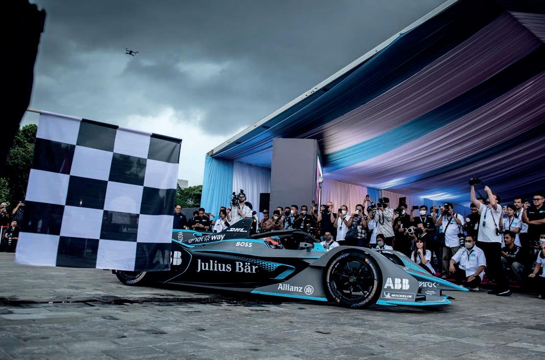
82 REDUCING WASTE | TYRES
Michelin was founding partner of Formula E, and proved itself capable of making a racing tyre to last a whole season, that works in both wet and dry conditions on different surfaces
»
‘Reducing the number of wets is meaningful because we scrap a lot of wet tyres because it just doesn’t rain, yet you still have to be prepared for it’
PA Wire
Matthieu Bonardel, head of motorsport business at Michelin
Efficiency drive
Aerodynamic pressure measurements are critical to understanding and improving race car performance. Pressure scanners are used to measure multiple pressures synchronously, accurately and repeatably, and to provide outputs in engineering units that are directly usable by the aerodynamicists. These have been used in aerospace-focused wind tunnels, and more recently, in automotive-focused wind tunnels. The wind tunnel and the CFD correlation has been important to validate the calculations with the experimentation. However, as wind tunnel testing time and CFD computations have become more restricted by the rule-makers, track testing has become more prevalent.
Any on-track testing in the past has been measured using wind tunnel-type pressure scanners that have been taken from their benign, controlled environment and fitted to the car to gather real-world vehicle data. However, finding space for these scanners has been a challenge. Avoiding the very high temperatures around the powertrain and drivetrain has moved the scanners further away from the ideal measuring locations.


It often also necessitated wrapping the scanners in heat and vibration isolation materials which ironically make the scanners even larger. Sometimes the scanners could only find a space in the side-pods, but radiators, oil coolers and other electronics that are normally housed there could also be a source of heat.

Response time
EvoScann® represented a new generation of thinking, based on a more effective distributed measurement network, where the scanners would be developed to offer a lower channel count. They would also be small, light, vibration- and temperature-resistant enough to be located around the car in close proximity to the measurement points. Scanners could therefore be mounted in places where space was extremely restrictive for any other technique. Tubing could still be used to make the scanners even more accessible, but these lengths were reduced, meaning that other issues such as time lags, attenuation of high frequencies and rapid changes would be minimised. This aimed to make the scanner as responsive to changes in the physical parameter as possible and for data to be of a much higher measurement integrity.
Further, with developments in communications it was no longer necessary to use proprietary software on serial buses to transmit the data. The EvoScann® could speak the same language as the
car electronics system – CANbus. The sensor could take its power from, and deliver the measurement data to, the digital network that runs around the car, collecting the data and storing or retransmitting it via the ECU.
These units were then examined and homologated by the FIA, so that the units are deemed to be passive devices that gather data and do not offer any benefits that could be considered illegal. This means that teams can use the scanners without concern or having to seek further approval.
Similar actions were also underway to ensure the improvement and enhancement of tried and trusted pressure scanners in the wind tunnel, such as those from Scanivalve. It was seen that reducing the size of these scanners was also advantageous, allowing the scanners to move from wind tunnel walls into the models themselves, where often 700 to 1000 channels of pressure data were required. As per the racecar onboard scanners, shortening the tubing lengths and bringing the measurement device, the pressure scanner, closer to the measurement points, offered many advantages, not least the improvements in data accuracy and speed from reducing frequency response issues, ensuring a much higher data measurement integrity.
Tunnel time
A number of additional features were developed both in the hardware and software to enhance usability and decrease downtime and set-up time, which is always an important consideration in any wind tunnel. Effectively they made the pressure scanner a complete data acquisition system. Ethernet was adopted as a standard communication protocol through a dedicated integrated web server and this enabled direct connection to a laptop or wind tunnel control system computer without interface boxes or special software, for direct compatibility to LabVIEW, for example. Compliance with IEEE 1588 made the system able to time-synchronise all the channels between multiple scanners to sub-microsecond accuracy. Hardware improvements included adding simple, fast and reliable integral valving to allow calibration, zero and purge functions to take place before a wind-on run, as well as removable headers adding the convenience of quick model changes and tube connections between runs.
Pressure scanners for both on-car and wind tunnel use have evolved significantly in recent years and continue to play a major part in the development of competitive race cars in many categories, helping their users find that allimportant winning edge. l

83 ADVERTORIAL
EvoScann® has produced a new set of sensors that offer ease of use and are FIA homologated to help generate accurate track testing results
» The units are proven to be passive devices that gather data and do not offer any benefits that could be considered illegal
The goal for the tyre manufacturers, then, is to have drivers go further on a set of tyres than they do currently. This can be done with some relatively simple changes to the sporting regulations. Right now, a driver usually has new tyres fitted when they take over driving, but this could change. Drivers could re-use their own tyres, or retain the tyres from the previous driver, or be able to drive for longer before being forced to change due to the regulations.
Construction industry
A tyre is constructed using rubber, natural oils and metals that form the structure. Each of these must be produced at a factory, which itself has to improve efficiency through such methods as increasing use of solar energy to power machines, as well as reducing the amount of water needed in the production process. Goodyear, for example, reduced energy consumption at its factories by 25 per cent in 2022 compared to 2010, and is continuing to push for further reductions.
‘What we call sustainable falls into two categories,’ explains Close. ‘We have bio-based materials that can be natural rubber, or the silica from the ash of the rice husk waste residue. So, take the carcass from rice, burn it, and from the ash you can take silica, which has the same properties as traditional silica.
'In some parts of the world, we are using this in passenger tyres because this can bring
in a high percentage of sustainable materials, but you need the volume. You can imagine in Asia, currently, this is more present than in Europe. This is one path you can increase the bio-based material. The other is oils.
‘The second part is the recycled material. We have a little bit of steel that is recycled from each tyre, but later we can use more of the recycled material. You take plastic bottles and from them you can generate material to use in tyres. This is of course under development right now, but the focus will always be on these two areas. It is difficult to give a precise percentage of tyre that will be renewable, or recycled, by 2035, but it will be significant.’
For Michelin, which prides itself on having an integrated approach to its racing effort, and feeding the technology developed there into production and heavy goods transport, the target is to go further than just using recycled material in its racing tyres. It is looking not for a headline percentage, but for something that can be scaled up to benefit all aspects of the business and has set a rudimentary roadmap for its racing programme to beat the production targets.
‘What we are trying to do is something that makes sense for Michelin, to help filter out the technology that can be considered in the rest of the tyre segments,’ confirms Bonardel. ‘Motorsport is the flagship. Once we have hit 53 per cent [renewable product in
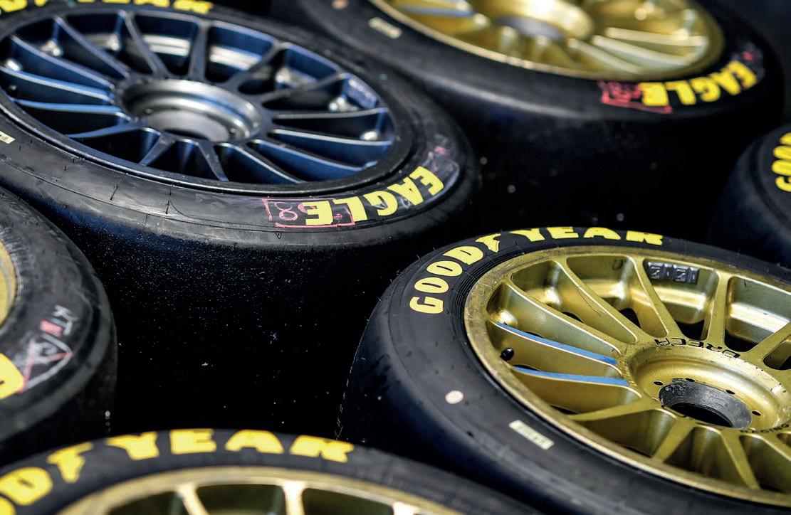
the tyre], okay, but then we need to produce it [in volume]. This is what we do with Moto E. In the H24 last year we proved we can get to 46 per cent, and this year we have produced 1000 tyres which is more significant than a show tyre on a show car. Then after 1000, our approach is to look at 5-10,000. Next year in IMSA and the WEC, we will go with a 40 per cent sustainable material for our wet tyres. We could do it for the slicks, but currently [we are limited by] the availability of stuff.
‘By 2025, we will probably hit 40 per cent for slicks in endurance. That is the idea. If we are at 40 per cent by then, we expect MotoE to be around 60 per cent. If we can achieve that, we will be at the 2030 target for the Michelin Group five years ahead of schedule.
84 REDUCING WASTE | TYRES
Goodyear is looking at two main avenues of sustainability development – renewable materials from which to make tyres,
and the
use
of
recycled products in their construction
» ‘It is difficult to say a precise percentage of tyre that will be renewable, or recycled, by 2035, but it will be significant’
Roland Close, Senior Manager, OE and car motorsport development at Goodyear
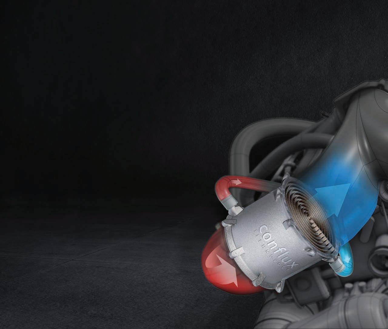

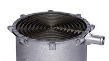


Ultra-high performance motorsport heat exchangers. - Low weight & pressure drop - Lower cost - Rapidly configured - 3D printed products Get in front with Conflux conflux-technology ConfluxTechnol1 Conflux Technology www.confluxtechnology.com Conflux Heat Exchangers deliver industry leading performance. Our motorsport products are scalable and configurable to unique boundary conditions, performance and packaging requirements. Learn more at confluxtechnology.com Cartridge Water Charge Air Cooler Oil/Water Cooler The cutting edge in additive manufacturing
The afterlife
Disposal of a racing tyre is the next challenge, and here the tyre companies are working hard to eliminate product sent to landfill. They both have systems in place to re-use old material, even if it doesn’t look on paper to be ‘green’. Both companies have deals with concrete manufacturers to use their waste products chopped up for fuel to fire the kilns.
‘To make concrete takes a lot of energy,’ confirms Bonardel. ‘Is it good? It is better than leaving it on track as at least it serves a purpose. It is not closed loop, though, so turning it back into a tyre would of course be the ultimate goal.
‘Another thing we are looking at, which is interesting, is that tyres are a very good material to use in the building industry, especially road construction. You can make roads out of tyres. We are in very good discussion with tracks, because they need to change their asphalt and they would love to do it with recycled tyres. I love that idea –worn race tyres produce race tracks sounds cool, and we can do that.
‘We have a small company we bought a couple of years ago that cuts tyres, reproduces it and works with road construction companies to produce asphalt. There is a roadmap to scale it. It is still not getting back into the tyre, which is another avenue, as it takes a lot of energy to do that. But in terms of technology, it is further down the road, and we are currently working on it.
‘We have a company that takes worn tyres and puts them in a machine. The hot temperatures can extract from the tyres pretty much everything. The biggest thing you can get from a tyre is oil, and that oil can be sold. Is it sustainable? No. But you are not taking it again from the ground and this is ramping up significantly.
‘I assume in the next 10-20 years we will be able to do it in a way that is simple and meaningful. It is important to have the technology, but we must have end-oflife options to re-utilise worn tyres and do something useful with them.’
Goodyear has a similar solution for its used tyres: ‘In passenger, we have end-of-life principles, but in racing, we take all the tyres back to our car manufacturing plants and, from there, the majority are going to cement kilns, because they can be used for energy recovery and diverse applications,’ says Close. ‘We are pleasd that we can use this wast, it is better for fuelling cement kilns, reducing the need for virgin fossil fuels. Tyres contain less carbon per unit of energy than coal or petroleum coke; therefore, using end of lift tyre as a fuel source reduces GHG emissions.
‘We are looking at other avenues too, so using parts of tyres for other things, but for the race tyres that is what we currently use so they don’t finish up in nature.’
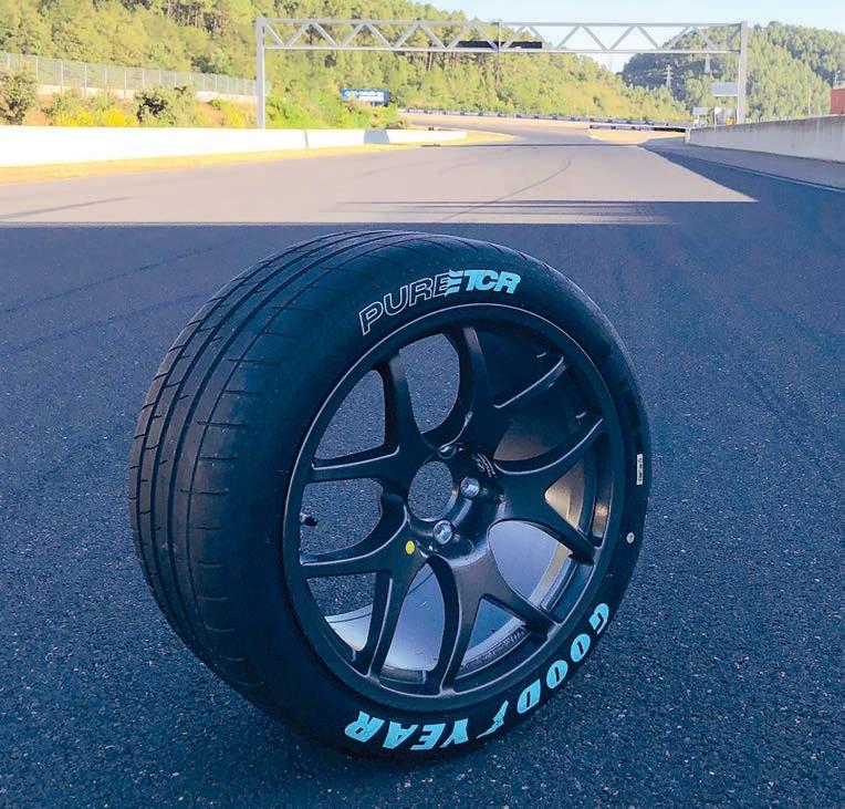
Weighty matters
The constant enemy of sustainability is weight, and here both passenger and racecars are facing similar issues with the advent of hybrid technology, particularly in F1 and the WEC. In the case of passenger cars, natural choice also comes into play. Despite all the negative publicity surrounding them, SUV sales are increasing, and the tyres on which they run must be designed to support the extra weight they carry around.
‘In general, we observe that vehicles are getting heavier, particularly in the electric vehicle sector,’ says Close. ‘The industry has created a new tyre standard, so that is the same tyre size but with a higher load capacity. That has been for about two years, and we have the first cars on the market using it. So, you have a 255/40R20, and you have HL before it. The tyre weight is only marginally heavier than the standard one, but the tyre is able to carry through its construction two or four times the load index.
'That was a request from our OEM partners. They asked us for such product to fit the wheelhouse, because they saw the load index of the normal tyre was not sufficient.’
It seems there are many areas in which the major tyre manufacturers can find improvements in sustainability, but perhaps the most important step was to make the major motorsport classes use a single brand to allow them to more thoroughly explore the different options available to them. Both Michelin and Goodyear have pushed hard, and continue to do so, in the process making racing tyres greener. l
86 REDUCING WASTE | TYRES
‘We check the different boxes for the motorsport tyres, and check the ones that accelerate innovation for the group.’
Goodyear is sole supplier to ETCR so can concentrate on sustainability goals, rather than battling with another manufacturer
»
‘In general, we observe that vehicles are getting heavier, particularly in the electric vehicle sector [so] the industry has created a new tyre standard, so that is the same tyre size but with a higher load capacity’
Roland Close, Senior Manager, OE and car motorsport development at Goodyear


www.racecar-engineering.com 87 motorsport@fclane.com +44 (0) 1403 790 661 LANEMOTORSPORT.COM VISIT OUR WEBSITE FOR TECHNICAL SUPPORT APPLICATIONS GUIDE CATALOGUES AND DATASHEETS 3D CAD MODELS ON-LINE SHOP AND NEW PRODUCTS INFO MOTORSPORT CONNECTORS AND ACCESSORIES IMMEDIATE DESPATCH OR RAPID ASSEMBLY WE CONNECT TECHNOLOGY No MOQ or MOV come and see us 12TH-13TH JAN 2023 STAND NO. E431
Prints charming
Additive manufacturing is transforming motorsport engineering, but how does it work?

Racecar spoke to experts involved in the 3D printing sector to get the inside line on this spellbinding technology
 By STEWART MITCHELL
You can’t really avoid additive manufacturing (AM) in motorsport these days. It’s everywhere, and for good reason. AM is a process of joining materials to make objects from 3D model data, usually layer upon layer, as opposed to traditional ‘subtractive’ manufacturing methodologies.
It is well understood that AM gives engineers more freedom to produce complex components, but it also has the potential to deliver a more significant impact on technology and manufacturing for industry than almost any other technology to date.
Motorsport is a constant exercise in continuously improving performance within rapid timeframes, so it’s not surprising to find this advanced manufacturing technology is a crucial element in implementing new designs and components. As Michael Fuller, CEO and founder of Conflux, a company that specialises in AM heat exchangers, says: ‘With AM, freedoms are simply realised in hitherto unmanufacturable geometries.’
The ‘sweet spot’ for AM lies in where designers want to create a component with only the required structures for its application, and optimise its size and weight. For example, designing hollow tubes and I-beams inside a component can help create a stiff internal structure with minimal weight.
How parts are loaded determines where material needs to be present, and often the centreline of a structure doesn’t require any material at all as the outside of the part carries the stress. ‘The key element is the part’s application, as this will dictate the technology, material and any post-processing requirements to ensure it is fit for purpose,’ says Samuel Persaud, head of projects at Graphite Additive Manufacturing.
‘Design for manufacture considerations are more relaxed for AM, allowing far greater ability to design without many of the constraints traditional manufacturing has,’ Fuller adds, ‘Limitations of imagination and creativity are common and, as with any industrialised manufacturing technology,
88 TECHNOLOGY | ADDITIVE MANUFACTURING
‘The tolerance and accuracy will very much be technology and material specific. Ultra-high resolution printers can build down to 25 microns’
Graphite AM
»
Kevin Lambourne, managing director, Graphite Additive Manufacturing
AM is used at all levels of motorsport. Here, Loughborough University Formula Student team’s steering wheel
Graphite AM
foundational training in design for additive manufacturing is a critical success factor for the roll out of the technology.’
With traditional manufacturing and surface finishing processes, manufacturers can produce tolerances of as little as 0.2microns, and a surface finish of Ra 0.2. This level of refinement is not yet possible with AM without severe post-processing of the part after it is printed. Even then, it’s unlikely to be quite that precise.
‘3D printing struggles to meet the tighter tolerances yielded with other traditional manufacturing methods, typically falling within +/-.125mm x, y or z direction,’ says
‘When used for additive manufacturing, it’s not uncommon to build a part, measure it and scale areas of the part file to dial in tighter tolerances against the printed part.’


Michael Littrell,
But high accuracy is certainly not impossible with AM. Kevin Lambourne, managing director of Graphite Additive Manufacturing, explains: ‘The tolerance and accuracy will very much be technology and material specific. Ultra-high-resolution printers can build down to 25 microns these days, but these machines are limited in the materials they can use and are only really suitable for small components.’
The surface finish with an additive manufactured part is usually much higher, or ‘rougher’, than precision subtractive techniques, so there are still plenty of components in the racecar and marketplace that need to be manufactured using more traditional methods.
‘Surface roughness aside, the microstructure across bulk geometries (>0.5mm) can be consistent, and this is imminently achievable and measurable,’ says Fuller. ‘In the case of thin walls and microfluidic channels, surface roughness can be in the same order of magnitude as the geometric features themselves.’
89
CEO of CIDEAS.
AM is particularly suited to complex geometries. This water outlet is made from carbon fibre-reinforced plastic Sinterworx C6 material
But whatever the limitations, there are plenty of 3D printing solutions to choose from. Indeed, Nathan Rawlings, UK manager at EOS, surmises that there are now so many types of additive manufacturing that there is likely a solution for most applications.
‘The market can appear quite confusing to someone with no previous experience in the field, and it depends on what you are trying to achieve,’ he says. ‘Some technologies are ideal for wind tunnel testing, for example, but you wouldn’t make a test, or functional, part with that technology.
‘There are four key technologies that are currently the most used and established: SLA (stereolithography), curing a resin in a vat with UV light; SLS (selective laser sintering) sintering polymer powders into 3D shapes; DMLS (direct metal laser sintering) melting metal powders into a 3D shape using high-power lasers; and FDM (fusion deposition modelling) a printing method, but in a structural way.


‘By units sold, FDM is the most popular technology worldwide at the moment due to its low cost and ease of use,’ Rawlings continues. ‘Due to speed, build volume and repeatability, multi-jet fusion (MJF) and SLS are becoming increasingly popular because of their potential for low-to-medium volume production applications.’
DLMS and FDM technologies are often used for the most demanding motorsport applications. However, Tim Chapman, head of additive manufacturing at McLaren Racing says: ‘Stereolithography technology and the materials have evolved, changing the way we use it. We don’t just manufacture prototypes
any more, we now produce many full-scale components and full-size tooling.
‘Wind tunnel testing is still the gold standard when assessing how every surface works together, either as an assembly or as a complete car. Our [Stratasys] Neo series of 3D printers have helped us to dramatically reduce the lead times of our aerodynamic wind tunnel components and projects.’
AM software

Additive manufacturing software is constantly improving, too. However, as Lambourne points out, ‘For most projects, the extra time and cost involved with FEA is not being utilised, but we hope to see this changing
Nathan
UK manager at EOS
90 TECHNOLOGY | ADDITIVE MANUFACTURING
»
‘Multi-jet fusion and SLS are becoming increasingly popular because of their potential for low-to-medium volume production applications’
Rawlings,
Confl ux
Conflux Technology’s 3D printed water to air charge cooler has very fine features and highly elaborate shapes on the inside Confl ux
Producing parts on site at Conflux’s vertically integrated additive manufacturing facility. AM technology is ideal for the complicated heat exchangers the company specialises in

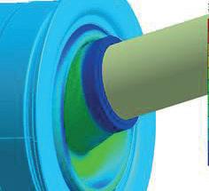


www.racecar-engineering.com 91 Design • Analysis • Manufacture We specialise in the design and development of technologically advanced polymer products for use within motorsport, defence and industry. Our design activities are dominated by expert use of the latest Finite Element Analysis software. We manufacture high performance polymer products including: • Low ProfileCVboots • High performance PTFE Linedshaftseals • Bladder accumulators • Custompolymersolutions • AV mounts For moreinformationvisit: www.active-polymer.com Tel: +44(0)7756 515772 • Email: support@active-polymer.com ACTIVE POLYMER TECHNOLOGIES Email: sales@graphite-am.co.uk By working with our loyal clients as a seamless extension of their business, we carefully select the correct material, technology and finishing option for each application. Our service is designed by Engineers for Engineers who need functional parts that work right, first time. SLA • SLS • MJF • SLM • FDM VAPOUR SMOOTHING
as the industry progresses further towards production. Designers have other great tools to optimise their parts, including 3D mesh structures to lightweight parts.’
A significant challenge facing component designers who want to manufacture parts using AM is defining the properties of the layered construction. The problem is that much of the CAD and FEA software cannot define a layered material’s properties because CAD programs work out each structure as an idealisation. The structure as it comes out of the AM machine is not ideal – it has rough surfaces and other imperfections – and the geometry at a microscopic level often diverges significantly from the idealisation.
But Fuller says there have been huge strides made across all disciplines of the AM value chain when it comes to CAD and FEA software for defining the properties of AM construction.
‘Design automation and topological optimisation tools are now very well suited to AM. Multi-physics modelling and simulation of the process itself are utilised to predict manufacturing phenomena [akin to mould flow or weld analysis] and, critically, the advent of in-process monitoring supports a very high level of real-time QA.’
AM operation
Most parts produced using AM are designed in 3D CAD and run through a program that turns them into 2D sections, which are then fed into the AM machine software as instructions for the build.
‘Conventional CAD / FEM software is developing increasingly in the direction of AM design with new features,’ says Rawlings. ‘A typical example is thread modelling. For a few years now, a thread can be modelled and manufactured using the thread feature with just a few clicks. Before that, the thread was only hinted at for a drawing, but there was no physical thread.’
The AM software automatically chooses the laser power and the speed at which it passes across the powder bed.
‘There are standard parameters for which these values are already specified,’ Rawlings explains. ‘Often, however, these parameters do not get the maximum out of the parts. With appropriate knowledge and experience, you can adapt or optimise the parameters for a specific part to achieve the best possible part quality and reduce the printing time.’
Detailing the popular polymer AM operations, Littrell comments: ‘The general principle of powder bed fusion is to print parts by solidifying the cross section of the CAD model into a fine layer of powder [usually a derivative of Nylon]. The un-solidified powder acts as a support structure, enabling complex geometries to be built quickly and in one piece. But, most
importantly, it allows for stacking parts above one another in the vertical z direction.
‘It’s very efficient and can yield a high volume of plastic parts quickly,’ Littrell adds. ‘Fused filament, or FDM technologies feed a plastic filament from a spool into a computer-controlled head and then it deposits hair-thin strands of melted plastic layer by layer. It is a very linear process and build speeds are somewhat slow, but extremely large and durable parts in several exotic plastics can be achieved.
‘In this technology, parts can be built solid, or large cross sections can be built with a honeycomb interior to reduce material usage and improve throughput. This process is ideal for jigs, fixtures, production aids, and may also be used in some aerospace applications.


‘Digital light processing (DLP) technologies have gained a lot of interest due to their small footprint, high speeds
and extremely high detailed parts,’ Littrell continues. ‘Although production sizes are limited, complex resins have been developed recently that are very close to traditional production-grade plastics.
‘Due to the material capabilities and fine feature resolution, DLP parts are finding their way into mass customised products such as low production vehicles components, connectors, fasteners and more.’
Metal AM
On the metal AM side of it, Samuel Persaud, head of projects at Graphite Additive Manufacturing, says: ‘SLS and MJF offers the most design flexibility, though restrictions that we watch for carefully are minimum wall thickness and getting access to remove unwanted material from inside components.’
It’s fair to say here that material science has been the key development path for AM.
92 TECHNOLOGY | ADDITIVE MANUFACTURING
Stratasys
The McLaren Formula 1 team uses Stratasys stereolithography 3D printing technology to help reduce its part production lead times
at CIDEAS
‘For any given technology, advancements in its materials has proven more beneficial than incremental hardware changes,’ says Lambourne. ‘That’s the very reason we formulated our own high performance Sinterworx C6 [carbon] and G4 [graphite] filled SLS materials. It can seem that material innovation in the market is fairly slow but, looking at the bigger picture, AM materials have developed to a price and performance level where they are more widely accepted for production parts.
‘The demand in adopting AM in recent years has increased the number of available performance materials,’ says Littrell. ‘Traceability is paramount, and unique features such as flame, smoke, toxicity ratings, ESD, chemical resistance, UV resistance, durability and other exotic characteristics are starting to show up.
‘The most notable area of growth in recent years is within photopolymers. Chemists are

now realising breakthrough combinations, inching closer to traditional thermoplastics.’
Usually, the machine’s computer will work out every layer’s power and speed to manufacture the part as desired.
‘In polymers, SLS machines have default settings and parameters that are embedded in the build profiles,’ explains Littrell. ‘An AM operator can fine tune and adjust the scanning speeds and laser intensity manually, even down to the individual part in a machine with varying part geometries. But the calibration of the optics, powder mixture, thermal management of the bed temperatures and proper cool down procedures are equally important.’
However, when it comes to the part’s surface vs its core volume, in some cases it might use different laser parameters to create different surface finishes or areas of the component. The resolution of each layer at the part’s boundary and its orientation determines the finish characteristics. If the surface takes the bulk of the load, it must be tailored differently from the interior section to create a different structure.
Persaud notes that, generally speaking, FDM is the only AM technology where hollowing parts is common practice. Nearly all of the other technologies will build parts solid if they are modelled as such. Increasing the laser’s power at the surface increases the resolution of the layers in that area.
Suppose you understand the principles of how the layering works on a particular material and have the freedom in the software of the given machine to change the laser’s power and speed. In that case, using this technique, you can get down to feature sizes of between 100 and 200 microns.

Heat exchangers and other components requiring a high surface area and volume ratio can be made much more efficient if the machine is tailored to the specific project.
‘The challenging and exacting nature of heat exchanger geometries necessitate bespoke process parameter sets to be developed, including, but not limited to, laser power and speed,’ says Fuller. ‘Surface finish is a function of multiple variables, including geometry orientation, process parameters, laser spot size, powder particle size distribution, gas flow, build plate geometry density, layer height, material type and quality and laser calibration.’
The trade off, then, is between speed and resolution – the higher the speed of the machine, the lower the resolution.
‘Largely, this is determined by the machine’s fixed resolution and the technology,’ says Persaud. ‘SLA is resin-based, offering a better surface finish over SLS or MJF, which requires bead blasting to remove surface powder. Vapour smoothing can be used to improve SLS and MJF as it removes layer lines and leaves a smooth, glossy surface.’
93
» ‘An AM operator can fine tune and adjust the scanning speeds and laser intensity manually’
Michael Littrell, CEO
Stratasys
McLaren’s array of Stratasys 3D printers. The team says the technology allows it to produce wind tunnel parts and other components very quickly and to a high level of accuracy
After the AM part is complete, postprocessing must take place to ensure it is going to perform as desired.

‘One of the most important elements is that the post-processing is already kept in mind when designing components, things like how to de-powder the component, or design the component so it needs little or no support structures,’ says Rawlings.
Post processing
Post-processing technology itself has evolved a long way in the last five years, too.
‘In the past, it would often be obvious a part was produced using AM as you would be able to see the build lines,’ says Rawlings. ‘This is no longer the case as companies now specialise in providing automated postprocessing, making it almost impossible to distinguish an AM part from more traditionally manufactured parts.’

Conflux utilises a Synchrotron light source to acquire a significant amount of highresolution CT scan data on its parts.
‘These large CT data sets [>15TB] are analysed with our in-house software suite [Conflux Quantify] to measure 3D pore density distribution and morphology, surface roughness, wall thickness, feature distances and identify critical defects,’ says Fuller.
Rawlings notes that AM machine development has been a process of continuous improvement too, where each new system is quicker, produces better quality parts and features more integrated quality controls as their evolution continues.

‘One characteristic about AM is the number of new machine manufacturers and start-ups joining, making it look like the evolution is happening over months. But, at the production end of the market, development is much slower, with the occasional jump,’ he says.
The need for speed
Formula 1 teams, for example, tend to use additive equipment 24/7, and full-scale production for AM parts has emerged in the past few years.

‘We find the high-definition components from our [Stratasys] Neo machines require minimal hand finishing, which allows much faster throughput to the wind tunnel,’ says Chapman. ‘In addition to speed, we can now produce wind tunnel parts with supreme accuracy, detail and surface finish, enabling our team to enhance testing and find innovative new ideas quickly and efficiently to improve performance.
‘I cannot overstate how important these benefits are in F1,’ Chapman adds. ‘With supertight deadlines to deliver cars to the next race, and where the smallest design iteration can make the difference between winning, losing or making up positions on the grid.’
94 TECHNOLOGY | ADDITIVE MANUFACTURING
EOS
EOS
The metal AM build process. Direct metal laser sintering (DML) melts the powders into a 3D shape using very high-powered lasers
Hyperganic’s rocket engine design study. The possible applications of AM are almost unlimited and it’s already used in many sectors
Major machine manufacturers have demonstrated automated factory solutions that promise to dramatically improve productivity across the complete AM process chain, from CAD / CAM file preparation to part build, heat treatment and build plate removal. These systems remove some of the manual stages inherent in the AM production process and automate them into one system.
These AM production systems require the user to load the build plate, and then everything runs automatically until the part is complete. The systems are modular, so they can be built up to individual user requirements to complete a part from a CAD / CAM file upload to a serviceable component. They also often feature a control module for the filter system, cooling system, powder delivery pumps, lasers and other peripherals, as well as multiple build modules, a heat treatment module, post-processing module and an inspection module.
Two build chambers can even be used so two parts can be made simultaneously and, because the powder handling is integrated into each module, different materials can be used in each build area.

Heat treatment
The heat treatment module in the system is critical as, when the build is complete, the heat treatment must be carefully controlled to ensure part quality is maintained. The AM process usually causes tension in a part and, if it is allowed to cool to room temperature before it is put through a heat treatment process, it can warp and be ruined.
Heat treatment does not occur in the build area. The modular system uses robotics to move the part to the heat treatment module.
After heat treatment, the component is transferred to a part removal module by robot, where it is turned upside down to remove any excess powder and then removed from its build plate by a roboticallycontrolled band saw. This must be done precisely to ensure the part is not damaged.
The part is then lowered into a bin with a foam inlay, turned upright, and then transferred into a final machining area.
The user can automatically set the entire system to run each manufacturing and posttreatment process and then return to the machine later to retrieve a completed part, which makes it a very convenient and timeefficient manufacturing process.
The use of additive manufacturing in motorsport certainly shows no signs of abating, and it is likely that a much higher percentage of components on a racecar will soon be manufactured using this technology. We will undoubtedly also see the emergence of larger, faster and more precise machines, and a great many more materials from which components can be made. l


95
Build Parts by CIDEAS
Build Parts by CIDEAS
CIDEAS used FDM, SLA and CLIP processes to create this highly detailed 100 per cent 3D printed trade show display engine model
SLA (stereolithography) was used to produce this HUD Navigation smart motorcycle helmet demonstrator. Accura 25 resin was chosen for its accuracy, durability and heat deflection. The process, which cures a resin with UV light, gives a good surface finish
» With power unit control strategies being the key to Formula 1 performance, data flow is imperative in ensuring a car is at its most competitive
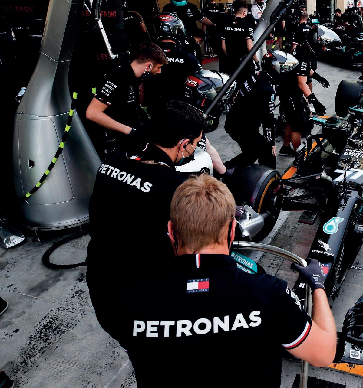

Sensor and sensibility
Racecar looks at the latest advances in sensor technology, and how Formula 1 in particular is using them to gain that ever-dwindling performance advantage
By Stewart Mitchell
PERFORMANCE | F1 SENSORS 96
1
Mercedes AMG Petronas Formula
The influence of data in contemporary motorsport cannot be understated. Formula 1 teams rely on it for almost every decision made, and most of that data is supplied by sensors onboard the car
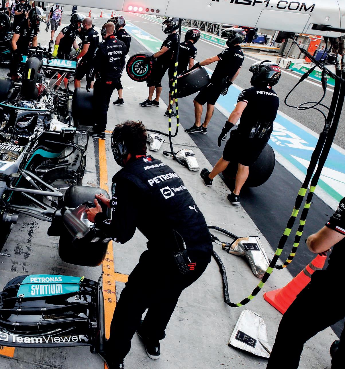
Acontemporary generation Formula 1 car is made up of around 25,000 components: 11,000 in the chassis; 6000 in the power unit (PU), electronics another 8500. Each of those must perform within a very specific window for the team and the driver to extract performance potential out of the car. To understand what the individual components are
doing, they must be instrumented and monitored by a host of sensors.
The most complex system onboard the cars is the power unit. Currently in F1, this comprises two motor generators, an internal combustion engine (ICE), battery store and control electronics. All of these are sub-systems in themselves and need constant supervising to ensure all elements are operating in the desired way.
97
Monitoring here involves using torque, pressure, temperature, position and speed sensors that relay information to the control electronics and via a telemetry link to trackside engineers and those back at the various factories. With power unit control strategies being the key to Formula 1 performance, this data flow is imperative in ensuring a car is always at its most competitive.
As with any racecar, packaging and weight are crucial design constraints, and every extra sensor added needs to be integrated, and accounted for, in the overall package. The challenge for teams and sensor manufacturers is to produce the smallest, lightest sensors possible, yet still ensure they will survive under race conditions and provide reliable data.
On top of the power unit engineers, the chassis engineers and aerodynamicists also have their own data demands. Engineers need to monitor the loads through chassis and suspension components to ensure they are operating within their design limits and are exploited for the desired performance when needed.
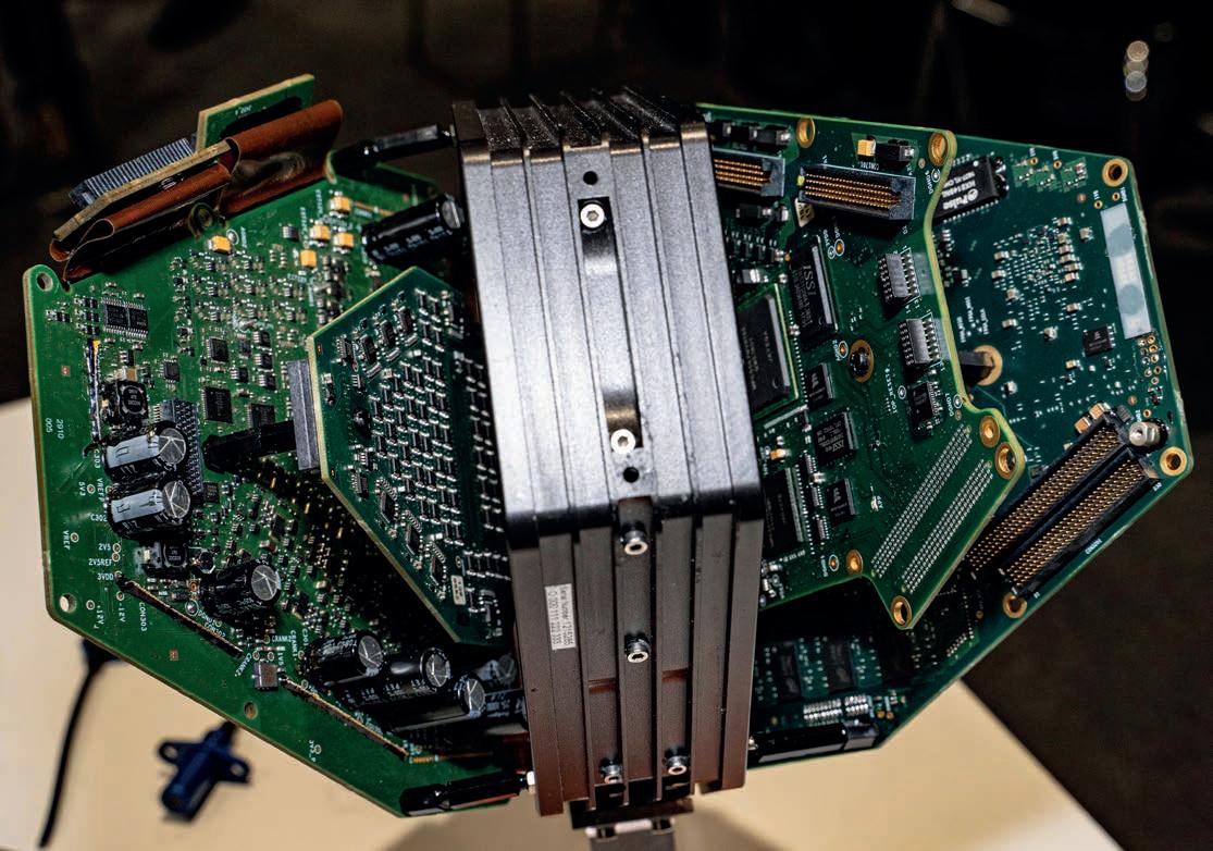
With the restrictions placed on ontrack testing and simulation resources in modern Formula 1, each track session is a vital data-gathering exercise.
Providing drive to the rear wheels is the power unit, which is a series of systems made up of components working in harmony, resulting in an output of torque. Measuring that torque is vital in a current Formula 1 car because the relationship between the accelerator pedal and the power unit is no longer an air metering device, it is essentially a torque controller.
Torque measurement
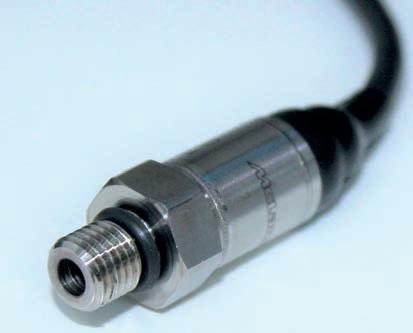
The car’s electronics determine how that torque is delivered, and govern the contribution of the ICE and energy recovery system (ERS) to the force that reaches the rear tyres. For power unit control strategies to be implemented, accurate torque measurement at various points in the system, including the kinetic motor generator unit (MGU-K) and the driveshafts, is mandatory.
Engineers use various methods for torque sensing. There are two core methods for measuring the torque applied to a shaft: twist angle and surface strain. The twist angle method unually requires a portion of the shaft being measured to be reduced in diameter, allowing twist under load. A pair of toothed discs attach at either end of this portion, and the twist angle can be determined using the phase difference
between magnetically or optically-detected tooth or gap patterns on each disc. Because the discs rotate at the same rate as the output shaft, torque can be measured during revolution. Adding extra toothed wheels at different degrees around the shaft can improve the accuracy of this measurement.
Another method, piezoresistive strain gauges, attach to the shaft to measure surface strain. Strain here is generally too small to be accurately measured directly, so standard practice is to use four gauges arranged in a Wheatstone bridge circuit. However, this arrangement
PERFORMANCE | F1 SENSORS 98
PMW Expo
Stewart Mitchell
Pressure sensors can be used to correlate air speed and applied load on aerodynamic components of racecars
The TAG 320 is the prescribed electronic control unit (ECU) for Formula 1. From here, driver and sensor inputs are processed to control the car as desired
isn’t ideal for rotating assemblies, as it requires coupling the sensor to a rotary transformer, or slip ring, to feed strainrelated current to the gauges, or receivers on static elements to acquire the signal from it in a non-contacting mode.
As such, the torque sensing technology favoured by the Formula1 fraternity is the magneto-elastic type. These produce current (signals) as a function of torsional stress, not strain. As a result, they are mechanically much stiffer than the conventional elastic torque sensors. They also offer a frequency response in the order of 2-4kHz, far higher than the other types.
Magneto-elastic surface stress measuring is also a non-contacting system and is ideal for measuring torque in a compact assembly.
There are two groups of magneto-elastic sensors and each measures magnetic quantities related to the surface shear stress in different ways. One measures magnetic permeability changes in the rotating element’s surface caused by stressinduced magnetic anisotropy. Magnetic anisotropy affects the permeance of a magnetic path and this sensor type uses a magnetising source and a sensing coil to measure the change in permeance. These are referred to as PB Type 1 sensors.
The second type, aptly named PB Type 2, uses the stress-inducing magnetic anisotropy to generate a measurable magnetic change in a permanently magnetised magnetoelastically active component.
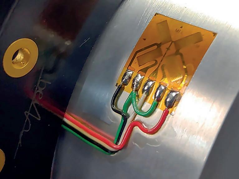
Magneto-elastic torque
Type 1 sensor are superior to traditional sensing methods because of their wireless transduction, combined with mechanical robustness. However, the permeabilitybased Type 1 magneto-elastic torque sensors suffer from the fact that permeability does not depend solely on applied torque. Even in a controlled environment, permeability can vary with temperature and magnetisation in any material composition. The result is that in many real-world settings, the changes due to these factors can exceed the changes in permeability caused by applied torque, making the measurements futile.
Type 2 sensors are therefore much more suitable for use in motorsport. They have many of the Type 1 sensor benefits and overcome most of the problems, too.
Type 2 sensors are made up of either a thin ring of magneto-elastically active material rigidly attached to a shaft, or by using a portion of the rotating element itself as the magneto-elastically active element. It still measures magneto-elastic energy associated with the principal stresses by which torque is transmitted along the shaft, though here, each moment will rotate towards the nearest positive main stress direction and away from the nearest negative one.
The re-orientation of the magnetisation results in a net axial magnetisation constituent. The divergence of this constituent at the poles of the magnetic field in the space around the shaft is measured with one or more magnetic field sensors. This gets around the problems associated with measuring permeability, allowing for very accurate and repeatable readings.
To achieve these, engineers can easily incorporate the polarised bands into the output shaft of a driveshaft on a racecar.
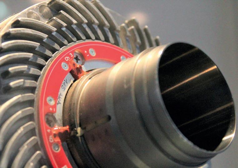
99
Binsfeld Engineering Inc
» Accurate torque measurement at various points in the system, including the kinetic motor generator unit (MGU-K) and the driveshafts, is mandatory [in Formula 1]
Stewart Mitchell
Strain sensor array arranged in a Wheatstone bridge pattern
Torque transducer coupled with electromagnetic frequency attenuating technology helps ensure the clear sensor readings required
Understanding the speed and acceleration of the rotating assemblies is fundamental in modern motorsport vehicle control and data acquisition. In the contemporary generation of F1 cars, the powertrain regulations present some challenges for sensor manufacturers in this arena. Since the dawn of the hybrid era, speed monitoring for the heat recovery motor generator unit (MGU-H) has been critical, and can see rotational speeds of 100,000rpm.
Measuring rotation
Rotational speed is generally measured using inductive, or Hall effect-type, sensors. Here, the magnetic field around a permanent magnet is manipulated by a ferrous toothed wheel that moves in front of an inductive sensor. A Hall effect sensor is a small sheet of semiconductor material arranged with a constant current flowing across it. A voltage proportional to the field strength and perpendicular to the current flow is then generated across the element in a magnetic field. A permanent magnet in the sensor supplies the magnetic field, so a magnetised wheel is unnecessary.
Voltage is the output, and this is generated in a coil of wire in a magnetic field. The coil and magnet are integrated into the sensor body for ease of installation. The induced voltage increases with the speed of movement of the ferrous object and decreases proportionally with distance from the end of the sensor and the moving element.
Hall effect sensors are used in the harshest of environments as they are robust and can measure very high rotational speeds. This makes them ideal for measuring turbo speed for example, or wheel speed.
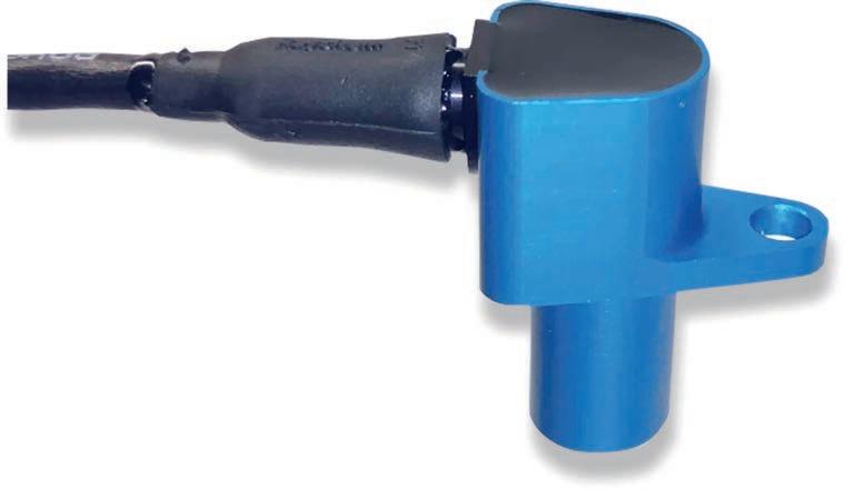
For MGU-H and turbocharger speed sensing, it is necessary to understand the rotating assembly’s characteristics, not just a simple speed reading. In the case of a turbocharger, the blades of the compressor rotor are highly stressed, and any degree of imbalance or vibration can result in catastrophic failure. Engineers can incorporate one or more optic or laser probes into the turbine housing to reflect a beam of light off the blade as it passes. If the blade is rotating at a constant rate, a particular blade should pass each sensor at a predictable time. Any deflection due to vibration causes blades to pass earlier or later than predicted.
The difference between these times can be used to calculate the deflection by measuring the delta from the measured and predicted position for each blade.
The most widespread method for monitoring the compressor blades is the tip timing method, which involves
taking an accurate measurement of the times the compressor blades pass by a series of unequally spaced sensors. A powerful laser with a small focus point and high-speed data acquisition can detect tiny vibrations at the turbine tips.
Stress and strain
Strain gauges are used predominantly in a Formula 1 car’s suspension and aerodynamic components. Wishbones and uprights are instrumented with several strain gauges to ascertain the loadings they are subject to. The part’s complexity and the axes along which it is loaded determine the orientation and number of gauges necessary, and the data type used to aid in understanding a car’s behaviour.
A strain gauge’s resistance varies as a force is applied across it. Stress and strain result when an external force is applied to an object. Stress is defined as the object’s internal resisting force, while a strain is any displacement or deformation that may occur. Load can be deduced by measuring these forces.
The most widely used type of strain gauges in motorsport are of the bonded foil type, a long standing and straightforward design that dates back to the sport’s origins. Here, a thin foil resistor grid bonds directly to the measured object’s surface. As the object is subjected to load and deforms, so too does the foil resistor. The resulting change alters the gauge’s resistance.
By measuring this change in resistance and comparing it to a value obtained by calibrating the sensor under laboratory conditions, the strain can be calculated.
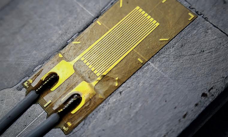
PERFORMANCE | F1 SENSORS 100
Strain gauge mounted to a measured component. In terms of a racecar, this is usually an aerodynamic or suspension component
A Hall effect sensor is a small sheet of semiconductor material arranged with a constant current flowing across it. Shown is a typical one for motorsport applications
Bosch Motorsport Michigan Scientific Corp
» Stress is defined as the object’s internal resisting force, while a strain is any displacement or deformation that may occur
The window gets smaller, PRESSURE is high.
Tyre wear management is key for championship-winning success. When critical data matters, choose Texense®!


Experts in bespoke sensing technologies
For over 20 years, TEXYS Group has remained a trusted supplier of championship winning teams, in providing reliable and accurate solutions for high end motorsport in single-seater, endurance racing, rallying and many more.
Contact us: sales@texense.com www.texysgroup.com
Photo: DR
TEMPERATURE gets hotter,
One of the problems with this type of gauge is the materials used to create the strain gauging elements are also prone to altering their resistance by external factors such as temperature. Differences in readings due to temperature come from two effects. Firstly, the gauge’s electrical resistance is somewhat temperature dependent, and so resistance will vary with temperature. The second factor is the differential in thermal expansion between the gauge and the test part, or substrate material.
A common method used to compensate for temperature changes is to have an additional gauge on one arm of the system isolated from any strain. This provides a reference output showing purely the change in resistance due to temperature. By isolating any environmental effects on the primary sensor, a more accurate value can then be calculated for the strain resistance.
When measuring strain in a part such as a wishbone, which will be subject to forces along several different axes as the car accelerates, brakes and turns, engineers will incorporate a number of strain gauges into the component, oriented with the various load paths to isolate each specific load case.
Load cells
Strain can also be measured by incorporating a load cell. Most Formula 1 teams use load cells in the front wing mounting struts to ascertain downforce distribution across a front wing. Similar units are mounted at the intersection between the rear wing pylons and the gearbox to do the same thing. The readings from both are fed into a model of the load paths and structural compensation models of the front and rear wing, from which the aerodynamic load distribution can be extrapolated.
In this example, gauges are bonded into the load cell structure, but they can also be tailored into functional components, minimising the impact on vehicle packaging.
All strain gauges need to incorporate a means of amplification to turn the output signal, in millivolts, into volts suitable for input into a data logger or ECU. Amplifiers will often fulfil other roles too, such as stabilising voltages to the strain gauges.
Some manufacturers also use dualoutput amplifiers that provide two different gain levels for different scenarios. As an example, when a car is driving along a straight, the load variations detected by a wishbone strain gauge will be reasonably small. To obtain detailed data here, engineers will use the high gain amplifier channel. But when the car runs over kerbs, loads spike and vary dramatically, so they might choose the data from the low gain amplifier channel.
Position technology
Measuring position or displacement on a given axis is the primary driver for understanding component operation and interrelation of systems in the car under dynamic scenarios.
Conventionally, F1 has used linear position technologies such as linear contacting potentiometers, linear variable differential transformers and magneto strictive sensors, though contemporary F1 cars use a non-contact position sensor that relies on magneto-resistive sensing technology to provide positional feedback.
The most significant benefit of this sensor type is the sensing element and target can be separated by most non-ferrous materials, including aluminium and stainless steel. Additionally, the sensing element and magnetic target can be separated by an air gap up to 40mm. This is particularly useful to power unit and drivetrain engineers, allowing sensor targets to be mounted in areas where it would not usually be possible to house a traditional sensor as
the sensitive sensing element is located outside the component it’s measuring.
As it consists of only a magnetic element, magneto-resistive sensing technology can be incorporated into existing components without significant design changes. This allows, for example, the movement of a piston within a complex hydraulic manifold to be measured, where it would be impossible to mount a conventional sensor. Here, the target element is embedded into the piston while the sensing element is located outside the manifold.
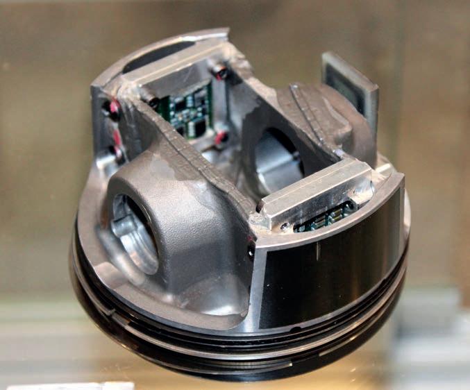
Some F1 teams, along with their sensor manufacturer partners, have created similar custom installations for both suspension and hydraulic applications.
Inevitably, sensor manufacturers will continue striving to produce smaller and more accurate sensing units, and to develop new techniques for measuring the previously un-measurable. Multiple functionalities embedded into singular sensor units is also likely to evolve, while detailed comprehension of the relationships between the various physical aspects being measured allows for extrapolation of multiple data sets from a single source.
In such multi-function sensor arrays, the extrapolation is achieved through algorithms coded into the receiver after measurement. Here, the multi-functional sensor data can be inputted into open loop models of system status, which engineers can feed into race strategy software or degradation models of the car. From there, teams can have a full picture of the car’s health and confidently decide on the next move. l
PERFORMANCE | F1 SENSORS 102
Position sensing technology embedded into a test piston. Using magneto-resistive technology, the sensor itself can be situated outside the piston chamber and still accurately record results
Stewart Mitchell
» Multiple functionalities embedded into singular sensor units is also likely to evolve


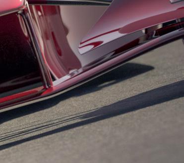


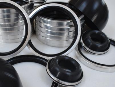

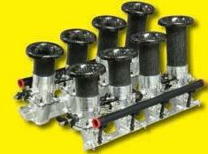


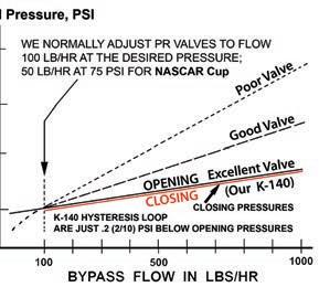


www.racecar-engineering.com 103 Call: +44 (0) 1264 316470 Email: enquiries@evolutionmeasurement.com www.EvolutionMeasurement.com Book a demonstration or request a quotation. Measurement without Compromise Gain the competitive advantage with on-car aroddynamic measurement Measurement without Compromise Gain the competitive advantage with on-car aerodynamic measurement EvoScann® miniature pressure scanner range includes: - Absolute or True-Differential measurement - 8 or 16 channels of digital data - Full-scale accuracy up to 0.1% - Scan speed up to 1000 Hz - Plug and play - Small, robust and lightweight GREGSEALTECHNOLOGYUKLT.indd1 9/12/0913:44:22 Tel +44(0)7756 515 772 E: richard.kennison@gstracing.co.uk www.gstracing.co.uk Custom Designed & Race Proven Polymer Sealing Solutions for Motorsport KINSLER We did the Lucas metering for the Can-Am: 60’s thru 70’s; still do. Any injection: Road race, Sprint cars, Boats, Indy 500, NASCAR Cup, Drags, Motorcycles, Bonneville, Pullers, Street, etc. EFI, Constant Flow, Lucas Mechanical sales@kinsler.com (248) 362-1145 Troy, Michigan USA Action Express Cadillac, ‘14, ‘15, ‘16, ‘17, IMSA Champs. ‘18, ‘21 Won driver & Mfr. Champs, overall ‘20 Daytona 24 Hrs. Pressure Relief Valve All the components, are carefully measured for each valve build, and recorded. This valve has the tightest loop of any valve we have tested: NASCAR Cup and INDY 500 cars EFI Injectors, all makes ofPressure ReliefValves and LucasMechanicalMeteringUnits,need 3 micron protection, but 3 micron filters plug up too quickly, so most racers use10 micron, which is too coarse. We made this new element for NASCAR Cup cars: 10 micron premium paper top layer to take out 95% of the dirt, with a 3 micron precision Fiberglass lower layer. Details: Kinsler.comhomepage. Monster MeshTM Filter 10/3 Element © Details: Kinsler.com Hard coated billet housing has four grooves above and below two diaphragms to lock them in place. Zero failures since introduction in 1996.
2030: a fuel odyssey
F1 is ramping up its search for the fuel of the future. Racecar looks at the new regulations and what we might expect to see happening in the next few years
By Peter Wright
The climate is changing. It is difficult to be unaware of the heat waves, wildfires, glacier and Arctic / Antarctic thawing and flooding emergencies currently affecting many nations as a consequence. Scientists agree that, even if the effect is a natural climate cycle, increased CO2 in the atmosphere is exacerbating the effect, and that only humans can do something about it.
More than 70 nations have pledged to achieve net zero CO2 emissions and so hopefully limit global temperature rise to under 1.5degC in 2050. To be successful requires immediate action to halve global emissions by 2030, and that is only around 90 months away from now.
Most people accept that F1’s emissions from the tailpipes of its cars is negligible in the great scheme of things, though the contributions of travelling fans is not. This issue is not confined to F1 among international sports, incidentally, but the difference is F1 has an increasing influence on the car buying and driving habits of consumers worldwide, there being around 1.5 billion cars serving the eight billion people currently living in the world.
Efficiency drive
In 2014, F1 set out to become more efficient with a set of power unit regulations that reduced the amount of fuel required to complete a race by one third. This has resulted

104 FORMULA 1 | ADVANCED SUSTAINABLE FUELS
» Hybrids are the type of power unit the automobile industry would like to sell, retaining their traditional ICEs while, at the same time, being able to claim sustainability credentials
Since 2014, F1 has been seeking to reduce its overall emissions, starting with fuel restrictions that drove hybrid power unit development, but that looks set to change again with the new 2026 Power Unit Technical Regulations that have been released in 2022


in hybrid powertrains that achieve over 50 per cent efficiency, compared with 30+ per cent of the high-revving V8s and V10s of the preceding generations.
In 2018, Liberty Media allowed Netflix to film Drive to Survive, and to repeat the process every year since. This excellent and entertaining documentary series has exposed F1 to a wider audience, especially in the USA. The resulting surge in popularity has caught the attention of, among others, the legacy motor industry and its essential partner, the energy industry.
These two industries, with their ICE factories, traditional dealer networks and fossil fuel reserves are under threat from EVs and renewable energy, and are staring the stranding of their assets in the face.
F1 cars are currently each limited to 110kg of petrol per race, an energy equivalent of about 1400kWh. Only a liquid hydrocarbon is able to achieve an acceptable energy density for storing this quantity of energy
in a car, and so F1 is inevitably limited to a hydrocarbon-burning ICE core power unit, topped up with as much energy as possible that can be recovered from the retarding of the car and from the exhaust ie a hybrid, compound-ICE power unit.
Hybrids are the type of power unit the automobile industry would like to sell, therefore retaining their traditional ICEs while, at the same time, being able to claim sustainability credentials.
Marketing partners
With the energy industry knowing it has to transition to zero net carbon, and hence find ways of making and supplying sustainable fuels, these two partners approached F1 (FIA and FOM) to encourage them to formulate new F1 power unit regulations along these lines. And then suggested they could become more involved in F1 as marketing partners. Just what FOM wanted, and the teams could see the value of their assets increasing.
In August this year, the FIA issued the 2026 F1 Power Unit Technical Regulations and this, in theory, allowed the auto manufacturers standing in the wings to step forward. These regulations are highly complex, but two fundamental changes stand out:
Firstly, the MGU-H is deleted. The consequence of this is that the overall efficiency of the power unit will decrease from something over 50 per cent to probably something under 40 per cent. Time will tell.
105
»
F1 has an increasing influence on the car buying and driving habits of consumers worldwide
Though emissions figures might grab the headlines, it’s the additional travel burden, including the legions of fans that go to watch races, that ramps up the global effect of motorsport
The argument for this is that the MGU-H is too high revving and too high temperature to use on a production ICE. Or, more likely, too hard for newcomers to catch up with the incumbents on development.
Secondly, the fuel used would be ‘Advanced Sustainable’ (AS). What are AS fuels? See Article 16.1, basic principles:
‘With regard to fuel, the detailed requirements of this Article are intended to ensure the use of Advanced Sustainable (AS) fuels comprising solely AS components, that are composed of certified compounds and refinery streams and fuel additives and to prohibit the use of specific power-boosting chemical compounds. The final, blended fuel must achieve a greenhouse gas (GHG) emissions savings, relative to fossilderived gasoline, of at least that defined for the transport sector in the EU Renewable Energy Directive RED(1), which was current on January 1st in the year prior to the relevant Formula One Championship.
‘The GHG savings calculation takes into account any net carbon emissions from landuse change, the energy used in harvesting and transporting the biomass and the production and processing of the advanced sustainable component. In any process where sustainable energy is used, this must be surplus to the local domestic requirements. Where available, GHG emission savings will be taken from the current EU Renewable Energy Directive (RED) or other equivalent, internationally recognised sources.
‘The use of these compounds and refinery streams in F1 fuel will be dependent on evidence indicating that the supplier is genuinely developing these compounds for use in commercial fuels and that they are available from plants capable of producing at least 5m3 per year or are commercially available at similar volumes from a third party. Acceptable compounds and compound classes are defined in 16.2 and 16.4.3.
‘In addition, to cover the presence of lowlevel impurities, the sum of components lying outside the 16.2 and 16.4.3 definitions are limited to 1% max m/m of the total fuel.’
Article 29, section 10(c) of Directive (EU) 2018 / 2001 for biofuels; Article 25, section 2 for RFNBO
In other words, they are defined in the same terms that global institutions have used to define the essential components of sustainability – net zero and zero carbon.
Advanced Sustainables
Whether you accept the need for any of these concepts being applied to CO2 emissions depends on your views on the scientific process of peer review and consensus, as applied to climate change.
However, under Article 16.2 Fuel Definitions, we find 16.2.8 Advanced Sustainable Component:

‘An Advanced Sustainable (AS) Component is one that is certified to have been derived from a carbon capture scheme, a renewable fuel of non-biological origin (RFNBO), municipal waste, or non-food biomass. Such biomass includes, but is not limited to, lignocellulosic biomass (including sustainable forest biomass), algae, agricultural residues
or waste, and dedicated non-food energy crops grown on marginal land unsuitable for food production. RFNBOs are considered renewable when the hydrogen component is produced in an electrolyser that uses new renewable electricity generation capacity.
‘Biocomponents from food crops can be regarded as an advanced sustainable component only if they have already fulfilled their food purpose (e.g. waste vegetable oil because it has already been used and is no longer fit for human consumption). Furthermore, the biomass, from which the advanced sustainable component was made, must not originate from land with high biodiversity such as undisturbed primary forest or woodland, land designated for nature protection or highly biodiverse grassland, and were in this state in or after January 2008.
‘Additionally, the biomass must not originate from any land with high-carbon stock such as wetlands and peatlands.’
106 FORMULA 1 | ADVANCED SUSTAINABLE FUELS
Zero carbon fuel, electrification and hydrogen are the favoured options on the table to meet the world’s transport needs but, rather than vote with our wallets, decision makers should look instead at sustainability and efficiency
»
The FIA has decided to encourage the energy industry to be heavily involved by making fuel supply competitive
This fuel component regulation is a mixture of permitted and banned sources, defined mainly in agricultural terms. These definitions apply to only 10 per cent of the current fuels, but in 2026 they will apply to the entirety of F1’s fuels.
So, the next question is how will they be policed on the ground? Article 16.5.1.c Fuel Approval states:
‘Certification must be presented to the FIA, from a recognised body, assuring the origin and the calculated GHG reduction of each AS compound and AS refinery stream blended into any Formula One fuel blend submitted to the FIA for approval.’

The FIA has therefore decided to encourage the energy industry to be heavily involved by making fuel supply competitive. While it will be interesting to see FIA inspectors in wellington boots checking fuel component sources, would it not have been

107
It is all well and good saying Advanced Sustainable fuels must be used, but their production and use then has to be policed
better if a single source AS fuel had been mandated, leading to the likes of ARAMCO and others bidding for the right to supply?
Drop-in solution
The physical properties of AS components are laid out in detail in the regulations and are very similar to conventional fossil fuel components used by F1. The idea being the new fuels will be a ‘drop-in’ solution.
But what exactly are Advanced Sustainable fuels, and what are their relevance to wheeled transport? Generally included in this category of fuels are e-fuels, synthetic fuels, e-methanol and hydrogen.
Why does society, or indeed F1, need them? To evaluate the various options, we have to look at the fundamentals, and to do that, we must go back to first principles. Please bear with me.
There are only two sources of energy available to us here on earth. Firstly, thermonuclear: the stars eg our sun; residual thermal energy ie geo-thermal; our attempts at nuclear fission and, one day, fusion. Secondly, orbital energy: energy extracted from tidal motion, powered by our moon orbiting the earth.
Avoiding the difficult and highly contentious subject of nuclear fission and fusion to generate electricity, our sun is the main and abundant source of energy exploited by humans. It takes a number of forms: solar thermal; solar voltaic; weather induced – wind, hydro; photosynthesis.
The latter generates hydrocarbons from the CO2 in the atmosphere and water, and provides biomass for consumption by animals such as humans, and combustion.
Historically, the biomass generated millions of years before we humans appeared has been stored as coal, oil and gas.
Only three atoms are essentially involved in the photosynthesis process: carbon, hydrogen, and oxygen. CO2 and H2O are combined with the energy of the photons from the sun that are absorbed by the green plant matter, and a variety of hydrocarbons are produced along with oxygen.
The natural world
The animal world uses the oxygen to burn the hydrocarbons it eats to power itself, emitting CO2 and water, and humans have learned to combust the hydrocarbons with oxygen to provide thermal energy from which heat and useful work can be derived, again emitting CO2 and water.
Clever humans figured out how to turn some of this work into electricity, which could be easily transmitted to provide heat, light or back into work. In the last century, they also figured out how to turn photons directly into electricity by liberating electrons from semiconductors such as silicon.
Left to its own devices, nature selects for efficiency. Examples, of which there are many, are streamlined fish, streamlined birds with hollow bones and tree leaves shaped for maximising photon absorption in the canopy.

But where there is an abundance of something, humans tend not to worry about efficiency or sustainability. Consider the plight of the 60 million buffalo roaming the North American plains in the late 18th century, reduced by the arrival of Europeans to a mere 500-600 by 1890. Humans have got away with 25 per cent efficient internal
combustion engines for wheeled transport for over 100 years, until the damage done by the waste products – CO2 and local pollutants – became evident, and the need to do something about them for our fundamental survival became clear.
The Stern Report of 1986 said the noninclusion of the cost of waste and emissions in the economics of energy production and use as the greatest and wide-ranging market failure the world has ever seen.
The options
The competition to find solutions have boiled down to two or three options for wheeled transport. They are as follows: ICE and net zero carbon fuel; ICE / hybrid and net zero carbon fuel; electrification; hydrogen.
Society tends to evaluate options economically, but the economics of energy supply are very complex – far too hard for an old engineer to fully understand. Politics, subsidies, speculation and taxes, amongst other things, cloud the issue. It is better then in the long term to evaluate and compare by considering efficiency and the sustainability of key resources. To do so can only be rigorously carried out using maths and science. One of the best sources of the maths and science on the subject is 100% Clean, Renewable Energy and Storage for Everything by Mark Z Jacobson, director of The Atmosheric / Energy Programme and professor of civil and environmental engineering at Stanford University.
The book lays out the science, technology, economics, policy and social aspects of the transition to renewable, sustainable energy in clear, easy to understand language. I recommend reading it.
Perhaps then, before we can understand why Formula 1 needs to implement Advanced Sustainable fuels, we must establish why society as a whole might need them, in preference to any of the other options currently on the table. l
108 FORMULA 1 | ADVANCED SUSTAINABLE FUELS
» The Stern Report of 1986 said the non-inclusion of the cost of waste and emissions in the economics of energy production and use as the greatest and wideranging market failure the world has ever seen
[include]
AdobeStock
» Left to its own devices, nature selects for efficiency. Examples
streamlined birds with hollow bones
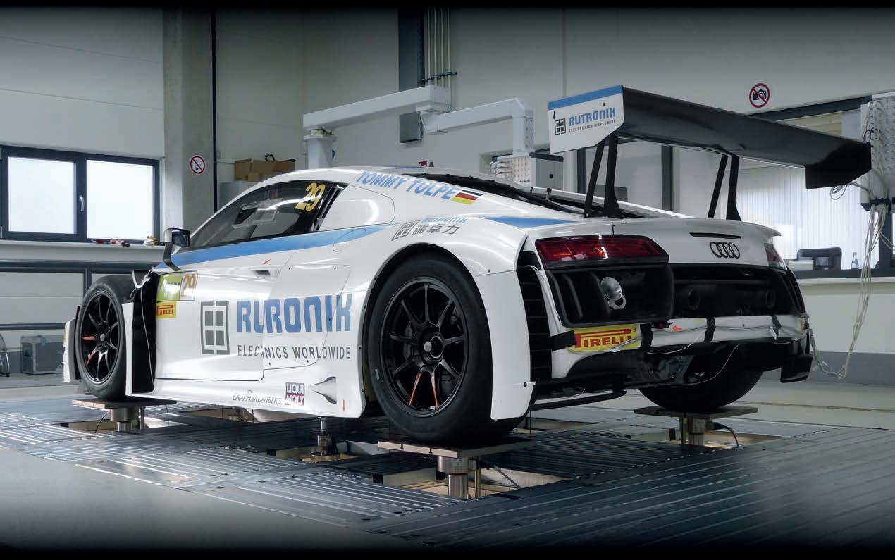


7-POST-RIG TESTING & SETUP OPTIMISATION SAVE YOUR TEST DATE NOW! TRE GmbH Nachtweide 35 67433 Neustadt/Germany Phone +49 6321 8786 0 info@tre-gmbh.com www.TRE-GmbH.com www.sevenposter.com www.TRE-GmbH.com Our state-of-the-art 7post rig is therefore equipped with twice as much travel as conventional poster rigs, which allows us to simulate tracks like the Nordschleife or even rally stages. We are already supporting many race and championship winning motorsport works teams in: Formula 1, DTM, GT3, GT4, LMP1, 24h Nordschleife, 24h Spa, Formula E, Pikes Peak Hill Climbing, WRC, WRX, TCR, Historic Motorsport, Club Racing & High Performance Cars.
TRE located near the Hockenheimring in Germany runs the latest and most advanced 7post rig and damper dyno in Europe. Our highest priority is to provide our customers with the best possible support, starting with the test planning, setup optimisation during the poster test and reporting. We can also support you during ontrack tests and data acquisition. Take full advantage of our Track-Replay feature to optimise and set your car up for every challenge.
The arguments for… and against
By Peter Wright
In the preceding article, we looked at the Advanced Sustainable (AS) fuels F1 has mandated for power units from 2026. In this follow-on feature, we look at why the world needs them to replace fossil fuels for combustion in increasingly obsolete internal combustion engines (ICE) for wheeled transport, and how they stack up against the alternative options available.
Currently, a medium-sized turbo diesel car returns around 45mpg. An imperial gallon of diesel embodies 49kWh, which means it travels 0.9 miles per kWh of energy in the tank. Add a hybrid system, and the mileage can be improved by around 30 per cent to 1.2m/kWh. Both these powertrains currently use carbon that is not present in the atmosphere and emit CO2 into it. They also emit local pollutants such as NOx and particulate matter (PM), reducing air quality
in urban areas and generating increasingly apparent public health issues.
If these ICEs use an AS fuel, one that derives carbon from the atmosphere, either from plants, biowaste or CO2 capture, they become roughly net zero carbon, but still emit local pollutants.
A medium-sized EV, on the other hand, will travel 4-5 miles per kWh, so it uses its available energy roughly four times more efficiently. Provided the energy is generated from a renewable source, it is zero carbon and produces zero local pollutants.
Using hydrogen in either a fuel cell EV or an ICE car is zero carbon, provided the energy used to make the hydrogen is renewable. NO x will be emitted by a hydrogen ICE but no PMs. A fuel cell EV is therefore inherently as efficient as a battery EV, but the conversion of hydrogen into electricity in the fuel cell is only
about 60 per cent efficient, therefore the miles per kWh are reduced to 2.5-3. A hydrogen-fuelled ICE is likely to be only as efficient as a hydrocarbon-fuelled version.
Intense development
Other factors come into the question of which powertrain will become the most economically and environmentally desirable. The energy density, including the storage system, favours liquid hydrocarbon, followed by hydrogen, and finally batteries. These parameters determine range, refuelling time and the cost of the vehicle.
Battery chemistries and construction are currently subject to intense development, and so-called ‘gigafactories’ to produce them are springing up all over the world. There is no shortage of lithium, just a demand that now outstrips supply of the refined product.

110 FORMULA 1 | ADVANCED SUSTAINABLE FUELS
soon-to-be-mandated
financially, environmentally and sustainably
How F1’s
Advanced Sustainable fuels stack up
against the alternative options
wayhomestudio/freepik.com
Formula 1 has backed the development of an e-Fuel, set to come into play with the series’ new power unit regulations in 2026, but not everyone agrees this is the answer
Lithium may well be replaced with sodium and, as there is no shortage of salt, we will not run out of electrolyte. Alternative cathodes and anodes are already in production that do not require cobalt or nickel.
In China, Geely has launched a car with a claimed 1000km range and 600kW charging in five minutes. When this technology comes to fruition, it will close the gap to hydrocarbonfuelled vehicles. Things are changing fast.

Source-to-tank
So far, we have only considered tank-to-wheel. A critical issue affecting the desirability and economics of the aforementioned energy options is the process to source / manufacture, refine/ distill and transport the energy, described as source-to-tank. These process technologies are also under intense development, but currently overall source-towheel efficiencies are as follows: battery EV – 70-80 per cent; hydrogen fuel cell – 25 per cent; e-fuel ICE – 15 per cent.
Converting the sun’s energy directly into electrons, either by photovoltaics, wind turbines or hydro-electric, and transporting that energy via copper wires to charging
points is overall around five times more efficient than converting biomass, waste or atmospheric CO2 to a hydrocarbon fuel in order to power wheels. There is no shortage of the sun’s energy, it is the best means of storing it that needs work.
Functionally, a ‘drop-in’ e-fuel will perform just the same as a fossil fuel equivalent. The difference is the fossil fuel was created out of the photosynthes of plant matter by natural high-temperature, high-pressure processes over a long time, at no cost. E-fuels, on the other hand, use a variety of speeded-up processes requiring an input of energy roughly equal to the energy embodied.
Whether this derives directly from the sun, as with algae, or from renewable electricity, or from fossil fuel determines its cost in monetary, environmental and sustainability terms.
Already EVs are more refined, have better secondary ride (unsprung to sprung mass ratio), more performance, require less maintenance, are lower cost to run and lower cost to own after around 10 to 20,000 miles than conventional ICE cars.
Personally, along with Elon Musk, Herbert Diess, the Chinese auto industry, Norway’s (and, increasingly, China’s, Europe’s and even now some car owners in the USA), I believe the future for wheeled transport, from micromobility to trucks, is electric. By 2030, the conversion to EVs will be well established. By then, F1’s e-fuel formula will be four years into its cycle, and maybe looking somewhat irrelevant to road transport systems, so why has the FIA and FOM gone down this route?
Making profit
In 2026, when the new F1 power unit regulations apply, the industry will be halfway to the generally accepted target of 2030 when no new ICE cars can be sold. The automobile industry outside China shakes its head and claims it is not possible. What they actually mean by that is they don’t know how to make a profit making EVs, especially small ones. Nor where the investment for the new production facilities required is going to come from.

And yet, existing and planned battery production investment is 5500GWh per year by 2030 – enough for 550 million 100kWh batteries – suitable for, but obviously not all for, cars. Wheeled vehicles will only require about one third of this energy storage capacity. What they say and what they do are not the same.
Meanwhile, the energy industry, with its vast fossil fuel reserves, shakes its head and suggests there will not be enough renewable
111
XPB Audi will enter F1 in 2026, and will be developing its own powertrain, citing sustainability as a key driver in its decision
» [The automobile industry] don’t know how to make a profit making EVs, especially small ones. Nor where the investment for the new production facilities required is going to come from
Williams Advanced Engineering recently launched its EVR, which focuses on the growing electric hypercar sector, with a lightweight composite structure and a high performance battery system
electricity to power all the vehicles the world will require. But with five times as much renewable electricity needed to produce the equivalent e-fuel for that number of vehicles, this argument falls down.
A continued commitment to ICE and hydrocarbon fuels would mean users have to revert to fossil fuels in the absence of sufficient e-fuel. Maybe this is what they hope for? I believe the automobile and energy industries simply want to delay the day car buyers have to buy EVs, and so stop purchasing hydrocarbon fuels for their personal transport. For sure, the energy industry will need to provide fuels for the residual ICE car park once consumers cease to purchase ICE cars, but it is likely the fuel will then be very expensive.
Marketing exercise
They see the new popularity of Formula 1 as a very effective way of marketing hydrocarbon-fuelled ICE vehicles. Take Porsche, for example, the EV expert that is also developing e-fuels. Porsche has hedged its bets with EVs, hybrids and traditional ICE models, yet already the electric Taycan is its third best seller after its ICE SUVs.

Porsche is right at the forefront of the performance car market, and decided to get involved in F1. How did it approach this?
Firstly, it planned to only become involved once the new power unit regulations were in place, and insisted the power unit was simplified (but less efficient) than the current ones, and that AS fuels were mandated.
Next, it chose to limit its allocation of resources to the development of the new Formula 1 ICE power unit by joining with Red Bull, using already established facilities, and benefitting from Honda’s (and effectively Mercedes’) F1 power unit technology by recruiting its experienced personnel.
Then Porsche sat down to negotiate control over Red Bull’s – very successful, it should be noted – F1 activities. It appears the manufacturer desired 50 per cent control of everything: technology, racing and marketing. Red Bull already brilliantly markets its core product – a canned energy drink. The company does this, not by demonstrating the technical superiority of its product, but simply by winning in F1 and a huge range of other exciting sports.
The management of the F1 team believes, rightly, that they succeed in this by maintaining total control over all relevant activities. Consequently, they could not agree on giving up partial control to Porsche.
To me, the most fascinating aspect of this unsuccessful negotiation is that Porsche’s primary desire to become involved in F1 was for the marketing of ICE engines and e-fuels. When it could not take control of one of the two most winning F1 teams, it walked away.
If, in the latter part of this decade, it becomes evident the world is converting to electricfication, and F1 is stuck with hydrocarbon combustion technology, will the remaining automobile and energy industries also walk away, leaving F1 with its need for high energy density hydrocarbon fuel simply as entertainment?
Advertising dollars
There is nothing wrong with this, in an era where media content competes intensely for advertising dollars, but this leads to the erosion of the sporting and technical aspects of the activity – the very foundations of F1.
If Formula 1 is no longer useful for marketing the power units of the automobile industry, and the fuels of the energy industry, where will the funding come from?
Alpine has stated it is investigating hydrogen as a possible future energy source for F1. Hydrogen is, of course, not a fuel, as it does not exist in any quantity on earth other than in combination with either oxygen or carbon. Rather, it is a storage medium for
electricity, which can then be converted back into electrons to power an EV, or combusted without CO2 emissions in an ICE.
It is unlikely hydrogen will become a significant energy source for road transport, but has potential as a substitute for natural gas as a source of thermal energy in industry. The logic for hydrogen as an F1 fuel needs further work, and is one of the questions F1 needs to address in the next 90 months. l

112 FORMULA 1 | ADVANCED SUSTAINABLE FUELS
BMW has introduced a fuel cell production system at its competence centre for hydrogen in Munich, clearly hinting at the German manufacturer’s vision for the future of mass motoring
» If F1 is no longer useful for marketing the power units of the automobile industry, and the fuels of the energy industry, where will the funding come from?
Polestar competed in the World Touring Car Championship with Volvo before evolving into an EV-only performance electric brand


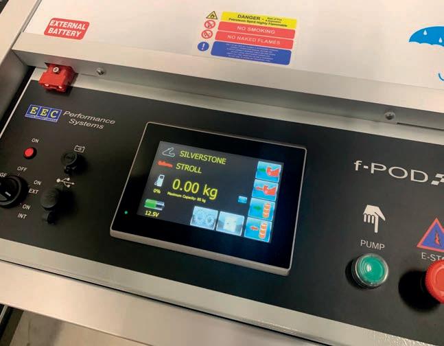

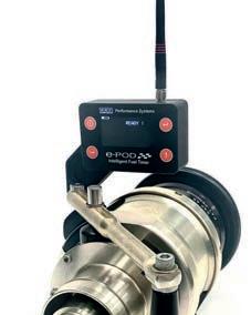


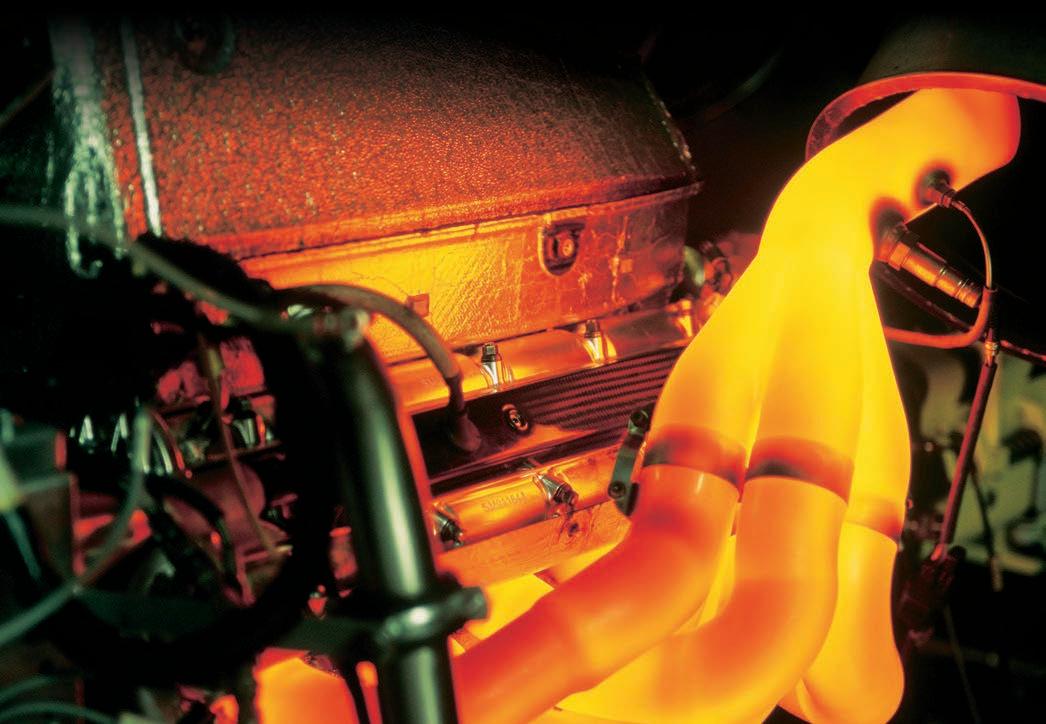


www.racecar-engineering.com 113 TitaniumEngineers.com ContactUs-UK@TitaniumEngineers.com Birmingham, UK: +44 (0)1675 464200 Leading Suppliers of High Strength Bars in Grades: Ti 6246 Ti Beta-C (Grade 19) Ti 6Al-4V (Grade 5) Nickel MP35N and more… Fast Reliable Service Technical Support with High Levels of Expertise Leading Suppliers of High Strength Bars in Grades: Ti 6246 Ti Beta-C (Grade 19) Ti 6Al 4V (Grade 5) Nickel MP35N and more… Fast Reliable Service Technical Support with High Levels of Expertise Capitalise: ContactUs UK@Titanium..... Update to: TitaniumEngineers.comIncluding: Endurance Fuel Rig Scales Wireless Intelligent Fuel Timer Wireless Fuel & Air Temperature Sensors Individual solutions You needa special solutionor a individual adjustment of our standard products? Simply contact us. Sensors for tyre and braking systems Sensors for exhaust gas systems Sensors for fluids Display devices and transmitters Thermocouples Accessories Therma Thermofühler GmbH Schreiner weg 8 51789 Lindlar Germany .Tel.:+492266 8026. www.therma-motorspor t.de The sophisticated Specialist in Thermo Sensor Technology for Motorsports. Temperature is our Business.
Fuel for thought
Iwrite this sat on an aeroplane to Charlotte. In my cabin there are three other people, 10 in Economy, none in Business and maybe some in First Class. Mid-pandemic, there is a daily flight from London to Charlotte and, instead of the usual nine hours, the reduced payload means it’s done in seven and a half hours. That’s not progress. The ’plane still burns one of earth’s most precious resources, albeit a bit less when it’s not full, and still owns an impressively large carbon footprint.
Now before anyone thinks, and then says it, I care deeply about my impact, and that of the motorsport industry, on the environment for a variety of reasons. Yes, I am aware I work in an industry that also burns a precious and finite resource, using transportation that isn’t clean and with materials that can be toxic. But that doesn’t mean I don’t care and that we don’t have a moral responsibility to our children.
I struggle with anyone that tells me my impact is minimal, or it’s hypocritical to work in racing and then try to be greener, especially industry insiders. It’s a bit like saying why bother using the toilet when you can just throw it out of the window, Middle Ages style.
Humans are resourceful and, in the case of transportation, we have seen a revolution in less than a century that was driven by the need to progress.
A new chapter
Alongside Formula E, now with an evolutionary car, we have also seen the debut of Extreme E, an electric World Touring Car Series and, in the future, a new electric GT series, which would bring pure electric racing into an endurance racing format. All of this is great. It’s a bit like 2006 when Audi re-introduced Le Mans to diesel and a new chapter in racing history was written.
Many at the time were appalled that such a fuel could even be considered in racing but, once you sift through the pessimism, you see progress was made in bringing a new technology to the track (nine overall Le Mans titles between Audi and Peugeot). However, I don’t think electric racing alone is enough.
An infrastructure is developing that is bringing electric technology to many Londoners, allowing them to move around the city in less noxious
gas-emitting vehicles. I don’t believe the London bubble is representative of anywhere else in the UK, though, and other areas are years away from enjoying the luxury of electric transportation.
For many smaller places, it simply won’t be economical to introduce electric charging structures because there isn’t local authority or central government investment available.
Thirty years ago, on a two-week placement in an engineering firm, I wrote an essay about a hydrogen car as part of a project on possible future projects. I’d been taught about climate change at school so this was exciting for me.
Sadly, that car was just a young engineer’s dream, and the options today are still too few. My interest in clean alternative fuels was spurred
about combining that fuel into a hybrid to achieve that? We haven’t done enough to find fuels that could be used in our current cars. I say this because in 2030 when no new ICE cars are sold, there are going to be lots of people stuck with ‘dirty’ cars paying high tariffs because they can’t afford an electric alternative, and without viable public transport because it is expensive and still being scaled back.
From race to road
Why does any of this apply to racing? Well, around 100 years ago, OEMs used racing to validate their road products and technology. But in the last 20 years, racing’s prowess hasn’t always revolutionised mainstream automotive engineering. In fact, on the powertrain front it could be argued that road cars are more advanced. Where OEMs might not want to commit to fully investing in alternative fuels for future models, they could finance niche racing products to explore alternatives on a small scale.
There are plenty of specialised engineering firms experimenting, and using their expertise could be an opportunity to develop a racing certified system.
This argument exists because we all want cars for movement and that is not likely to change anytime soon. So as a society, and an industry, we need to show what is possible. There can be options that still remain true to the art of racing, whilst perhaps sparking complementary technologies using fossil fuel alongside the battery industry.
by a research paper written by Aquafuel who provided Formula E with fuel to use in generators to charge the batteries. It looked into the use of glycerine from naturally occurring algae to power ICE, and with some success.
It doesn’t provide the same power and performance as petrol, but also doesn’t produce any NOx, CO or CO2. So, while it might not power the next Le Mans winner, it does have cleaner credentials for everyday use.

Except for electric, there is likely no other fuel source out there that provides torque and power with the same expectation of fossil fuel. So how
To be clear, electric has its own controversial and moral issues, so it isn’t the golden ticket to all our green, ethical and sustainable transport.
I feel the governing bodies are moving too slowly, with a hang up on equivalence and the past. There are so many clever minds in this business, it would be refreshing to see a partnership between racing and automotive bring a new perspective on our every day. It’s never too late to try something new! l
Leena Gade is race engineer at Multimatic Engineering UK

THE ASPHALT STORIES | LEENA GADE 114
Are OEMs and the motorsport industry missing a trick?
»
While OEMs might not want to commit to fully investing in alternative fuels for future models, they could finance niche racing products to explore alternatives
Audi diesel technology was a revolution at Le Mans. Motorsport needs its next fuel revolution
Ferdi Kräling Motorsport-Bild GmbH


Watch now
I’m not there to be second, especially when you know there’s a championship on the line, you are going to go for it. Performance comes from within For Max Verstappen performance comes from within, just like Mobil 1™ engine oil. Unleash your #Desire
© 2022 ExxonMobil. All trademarks used herein are trademarks or registered trademarks of Exxon Mobil Corporation or one of its subsidiaries. Other trademarks shown are the property of their respective owners.