17 minute read
ADDITIVE MANUFACTURING


Prints charming
Additive manufacturing is transforming motorsport engineering, but how does it work? Racecar spoke to experts involved in the 3D printing sector to get the inside line on this spellbinding technology
By STEWART MITCHELL
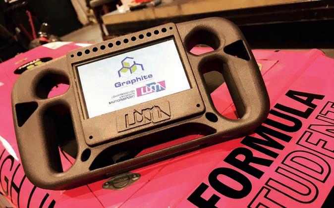
Graphite AM
You can’t really avoid additive manufacturing (AM) in motorsport these days. It’s everywhere, and for good reason. AM is a process of joining materials to make objects from 3D model data, usually layer upon layer, as opposed to traditional ‘subtractive’ manufacturing methodologies.
It is well understood that AM gives engineers more freedom to produce complex components, but it also has the potential to deliver a more significant impact on technology and manufacturing for industry than almost any other technology to date.
Motorsport is a constant exercise in continuously improving performance within rapid timeframes, so it’s not surprising to find this advanced manufacturing technology is a crucial element in implementing new designs and components. As Michael Fuller, CEO and founder of Conflux, a company that specialises in AM heat exchangers, says: ‘With AM, freedoms are simply realised in hitherto unmanufacturable geometries.’
The ‘sweet spot’ for AM lies in where designers want to create a component with only the required structures for its application, and optimise its size and weight. For example, designing hollow tubes and I-beams inside a component can help create a stiff internal structure with minimal weight.
How parts are loaded determines where material needs to be present, and often the centreline of a structure doesn’t require any material at all as the outside of the part carries the stress. ‘The key element is the part’s application, as this will dictate the technology, material and any post-processing requirements to ensure it is fit for purpose,’ says Samuel Persaud, head of projects at Graphite Additive Manufacturing.
‘Design for manufacture considerations are more relaxed for AM, allowing far greater ability to design without many of the constraints traditional manufacturing has,’ Fuller adds, ‘Limitations of imagination and creativity are common and, as with any industrialised manufacturing technology,

foundational training in design for additive manufacturing is a critical success factor for the roll out of the technology.’
With traditional manufacturing and surface fi nishing processes, manufacturers can produce tolerances of as little as 0.2microns, and a surface fi nish of Ra 0.2. This level of refi nement is not yet possible with AM without severe post-processing of the part after it is printed. Even then, it’s unlikely to be quite that precise.
‘3D printing struggles to meet the tighter tolerances yielded with other traditional manufacturing methods, typically falling within +/-.125mm x, y or z direction,’ says Michael Littrell, CEO of CIDEAS. ‘When used for additive manufacturing, it’s not uncommon to build a part, measure it and scale areas of the part fi le to dial in tighter tolerances against the printed part.’
But high accuracy is certainly not impossible with AM. Kevin Lambourne, managing director of Graphite Additive Manufacturing, explains: ‘The tolerance and accuracy will very much be technology and material specifi c. Ultra-high-resolution printers can build down to 25 microns these days, but these machines are limited in the materials they can use and are only really suitable for small components.’
The surface fi nish with an additive manufactured part is usually much higher, or ‘rougher’, than precision subtractive techniques, so there are still plenty of components in the racecar and marketplace that need to be manufactured using more traditional methods.
‘Surface roughness aside, the microstructure across bulk geometries (>0.5mm) can be consistent, and this is imminently achievable and measurable,’ says Fuller. ‘In the case of thin walls and microfl uidic channels, surface roughness can be in the same order of magnitude as the geometric features themselves.’
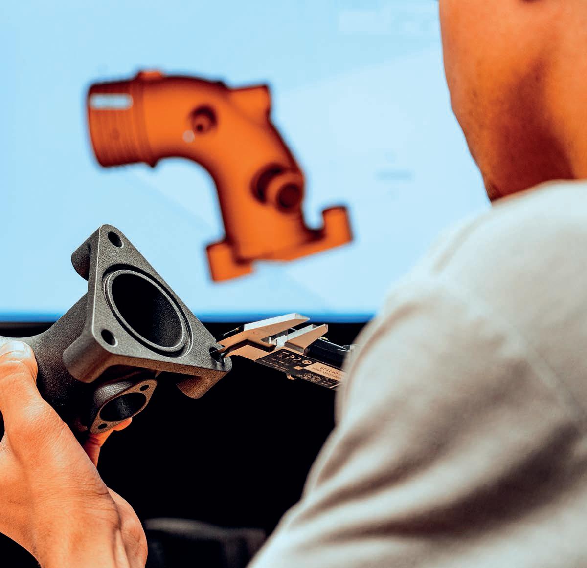
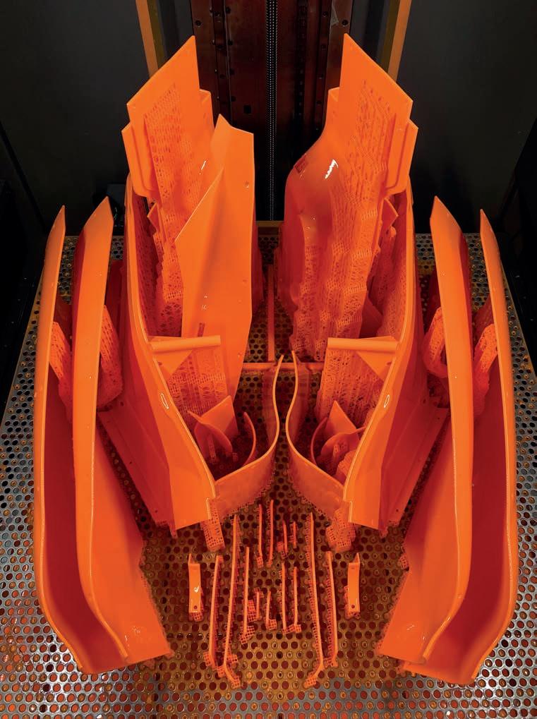
AM is particularly suited to complex geometries. This water outlet is made from carbon fibre-reinforced plastic Sinterworx C6 material
But whatever the limitations, there are plenty of 3D printing solutions to choose from. Indeed, Nathan Rawlings, UK manager at EOS, surmises that there are now so many types of additive manufacturing that there is likely a solution for most applications.
‘The market can appear quite confusing to someone with no previous experience in the fi eld, and it depends on what you are trying to achieve,’ he says. ‘Some technologies are ideal for wind tunnel testing, for example, but you wouldn’t make a test, or functional, part with that technology.
‘There are four key technologies that are currently the most used and established: SLA (stereolithography), curing a resin in a vat with UV light; SLS (selective laser sintering) sintering polymer powders into 3D shapes; DMLS (direct metal laser sintering) melting metal powders into a 3D shape using high-power lasers; and FDM (fusion deposition modelling) a printing method, but in a structural way.
‘By units sold, FDM is the most popular technology worldwide at the moment due to its low cost and ease of use,’ Rawlings continues. ‘Due to speed, build volume and repeatability, multi-jet fusion (MJF) and SLS are becoming increasingly popular because of their potential for low-to-medium volume production applications.’
DLMS and FDM technologies are often used for the most demanding motorsport applications. However, Tim Chapman, head of additive manufacturing at McLaren Racing says: ‘Stereolithography technology and the materials have evolved, changing the way we use it. We don’t just manufacture prototypes any more, we now produce many full-scale components and full-size tooling.
‘Wind tunnel testing is still the gold standard when assessing how every surface works together, either as an assembly or as a complete car. Our [Stratasys] Neo series of 3D printers have helped us to dramatically reduce the lead times of our aerodynamic wind tunnel components and projects.’
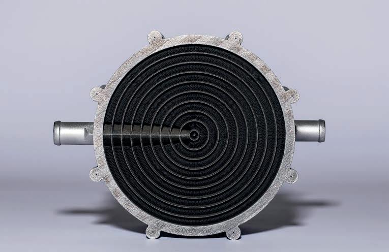
Conflux Technology’s 3D printed water to air charge cooler has very fine features and highly elaborate shapes on the inside
AM software
Additive manufacturing software is constantly improving, too. However, as Lambourne points out, ‘For most projects, the extra time and cost involved with FEA is not being utilised, but we hope to see this changing
» ‘Multi-jet fusion and
Nathan Rawlings, UK manager at EOS

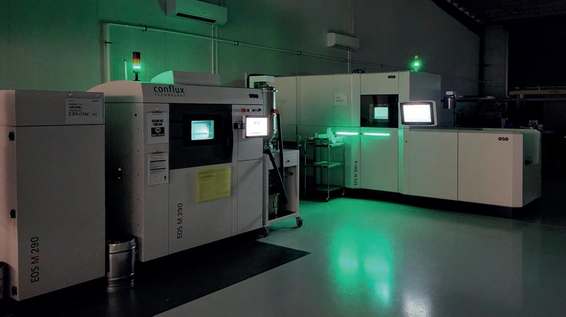
Producing parts on site at Conflux’s vertically integrated additive manufacturing facility. AM technology is ideal for the complicated heat exchangers the company specialises in
as the industry progresses further towards production. Designers have other great tools to optimise their parts, including 3D mesh structures to lightweight parts.’
A signifi cant challenge facing component designers who want to manufacture parts using AM is defi ning the properties of the layered construction. The problem is that much of the CAD and FEA software cannot defi ne a layered material’s properties because CAD programs work out each structure as an idealisation. The structure as it comes out of the AM machine is not ideal – it has rough surfaces and other imperfections – and the geometry at a microscopic level often diverges signifi cantly from the idealisation.
But Fuller says there have been huge strides made across all disciplines of the AM value chain when it comes to CAD and FEA software for defi ning the properties of AM construction.
‘Design automation and topological optimisation tools are now very well suited to AM. Multi-physics modelling and simulation of the process itself are utilised to predict manufacturing phenomena [akin to mould fl ow or weld analysis] and, critically, the advent of in-process monitoring supports a very high level of real-time QA.’
AM operation
Most parts produced using AM are designed in 3D CAD and run through a program that turns them into 2D sections, which are then fed into the AM machine software as instructions for the build.
‘Conventional CAD / FEM software is developing increasingly in the direction of AM design with new features,’ says Rawlings. ‘A typical example is thread modelling. For a few years now, a thread can be modelled and manufactured using the thread feature with just a few clicks. Before that, the thread was only hinted at for a drawing, but there was no physical thread.’
The AM software automatically chooses the laser power and the speed at which it passes across the powder bed.
‘There are standard parameters for which these values are already specifi ed,’ Rawlings explains. ‘Often, however, these parameters do not get the maximum out of the parts. With appropriate knowledge and experience, you can adapt or optimise the parameters for a specifi c part to achieve the best possible part quality and reduce the printing time.’
Detailing the popular polymer AM operations, Littrell comments: ‘The general principle of powder bed fusion is to print parts by solidifying the cross section of the CAD model into a fi ne layer of powder [usually a derivative of Nylon]. The un-solidifi ed powder acts as a support structure, enabling complex geometries to be built quickly and in one piece. But, most importantly, it allows for stacking parts above one another in the vertical z direction.
‘It’s very effi cient and can yield a high volume of plastic parts quickly,’ Littrell adds. ‘Fused fi lament, or FDM technologies feed a plastic fi lament from a spool into a computer-controlled head and then it deposits hair-thin strands of melted plastic layer by layer. It is a very linear process and build speeds are somewhat slow, but extremely large and durable parts in several exotic plastics can be achieved.
‘In this technology, parts can be built solid, or large cross sections can be built with a honeycomb interior to reduce material usage and improve throughput. This process is ideal for jigs, fi xtures, production aids, and may also be used in some aerospace applications.
‘Digital light processing (DLP) technologies have gained a lot of interest due to their small footprint, high speeds and extremely high detailed parts,’ Littrell continues. ‘Although production sizes are limited, complex resins have been developed recently that are very close to traditional production-grade plastics.
‘Due to the material capabilities and fi ne feature resolution, DLP parts are fi nding their way into mass customised products such as low production vehicles components, connectors, fasteners and more.’
The McLaren Formula 1 team uses Stratasys stereolithography 3D printing technology to help reduce its part production lead times
Metal AM
On the metal AM side of it, Samuel Persaud, head of projects at Graphite Additive Manufacturing, says: ‘SLS and MJF off ers the most design fl exibility, though restrictions that we watch for carefully are minimum wall thickness and getting access to remove unwanted material from inside components.’
It’s fair to say here that material science has been the key development path for AM.
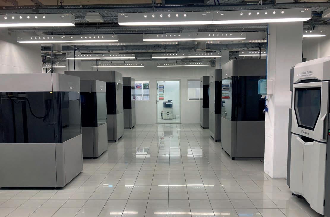
McLaren’s array of Stratasys 3D printers. The team says the technology allows it to produce wind tunnel parts and other components very quickly and to a high level of accuracy

Michael Littrell, CEO at CIDEAS
‘For any given technology, advancements in its materials has proven more benefi cial than incremental hardware changes,’ says Lambourne. ‘That’s the very reason we formulated our own high performance Sinterworx C6 [carbon] and G4 [graphite] fi lled SLS materials. It can seem that material innovation in the market is fairly slow but, looking at the bigger picture, AM materials have developed to a price and performance level where they are more widely accepted for production parts.
‘The demand in adopting AM in recent years has increased the number of available performance materials,’ says Littrell. ‘Traceability is paramount, and unique features such as fl ame, smoke, toxicity ratings, ESD, chemical resistance, UV resistance, durability and other exotic characteristics are starting to show up.
‘The most notable area of growth in recent years is within photopolymers. Chemists are now realising breakthrough combinations, inching closer to traditional thermoplastics.’
Usually, the machine’s computer will work out every layer’s power and speed to manufacture the part as desired.
‘In polymers, SLS machines have default settings and parameters that are embedded in the build profi les,’ explains Littrell. ‘An AM operator can fi ne tune and adjust the scanning speeds and laser intensity manually, even down to the individual part in a machine with varying part geometries. But the calibration of the optics, powder mixture, thermal management of the bed temperatures and proper cool down procedures are equally important.’
However, when it comes to the part’s surface vs its core volume, in some cases it might use diff erent laser parameters to create diff erent surface fi nishes or areas of the component. The resolution of each layer at the part’s boundary and its orientation determines the fi nish characteristics. If the surface takes the bulk of the load, it must be tailored diff erently from the interior section to create a diff erent structure.
Persaud notes that, generally speaking, FDM is the only AM technology where hollowing parts is common practice. Nearly all of the other technologies will build parts solid if they are modelled as such. Increasing the laser’s power at the surface increases the resolution of the layers in that area.
Suppose you understand the principles of how the layering works on a particular material and have the freedom in the software of the given machine to change the laser’s power and speed. In that case, using this technique, you can get down to feature sizes of between 100 and 200 microns.
Heat exchangers and other components requiring a high surface area and volume ratio can be made much more effi cient if the machine is tailored to the specifi c project.
‘The challenging and exacting nature of heat exchanger geometries necessitate bespoke process parameter sets to be developed, including, but not limited to, laser power and speed,’ says Fuller. ‘Surface fi nish is a function of multiple variables, including geometry orientation, process parameters, laser spot size, powder particle size distribution, gas fl ow, build plate geometry density, layer height, material type and quality and laser calibration.’
The trade off , then, is between speed and resolution – the higher the speed of the machine, the lower the resolution.
‘Largely, this is determined by the machine’s fi xed resolution and the technology,’ says Persaud. ‘SLA is resin-based, off ering a better surface fi nish over SLS or MJF, which requires bead blasting to remove surface powder. Vapour smoothing can be used to improve SLS and MJF as it removes layer lines and leaves a smooth, glossy surface.’
After the AM part is complete, postprocessing must take place to ensure it is going to perform as desired.
‘One of the most important elements is that the post-processing is already kept in mind when designing components, things like how to de-powder the component, or design the component so it needs little or no support structures,’ says Rawlings.
Post processing
Post-processing technology itself has evolved a long way in the last fi ve years, too.
‘In the past, it would often be obvious a part was produced using AM as you would be able to see the build lines,’ says Rawlings. ‘This is no longer the case as companies now specialise in providing automated postprocessing, making it almost impossible to distinguish an AM part from more traditionally manufactured parts.’
Confl ux utilises a Synchrotron light source to acquire a signifi cant amount of highresolution CT scan data on its parts.
‘These large CT data sets [>15TB] are analysed with our in-house software suite [Confl ux Quantify] to measure 3D pore density distribution and morphology, surface roughness, wall thickness, feature distances and identify critical defects,’ says Fuller.
Rawlings notes that AM machine development has been a process of continuous improvement too, where each new system is quicker, produces better quality parts and features more integrated quality controls as their evolution continues.
‘One characteristic about AM is the number of new machine manufacturers and start-ups joining, making it look like the evolution is happening over months. But, at the production end of the market, development is much slower, with the occasional jump,’ he says.
The need for speed
Formula 1 teams, for example, tend to use additive equipment 24/7, and full-scale production for AM parts has emerged in the past few years.
‘We fi nd the high-defi nition components from our [Stratasys] Neo machines require minimal hand fi nishing, which allows much faster throughput to the wind tunnel,’ says Chapman. ‘In addition to speed, we can now produce wind tunnel parts with supreme accuracy, detail and surface fi nish, enabling our team to enhance testing and fi nd innovative new ideas quickly and effi ciently to improve performance.
‘I cannot overstate how important these benefi ts are in F1,’ Chapman adds. ‘With supertight deadlines to deliver cars to the next race, and where the smallest design iteration can make the diff erence between winning, losing or making up positions on the grid.’
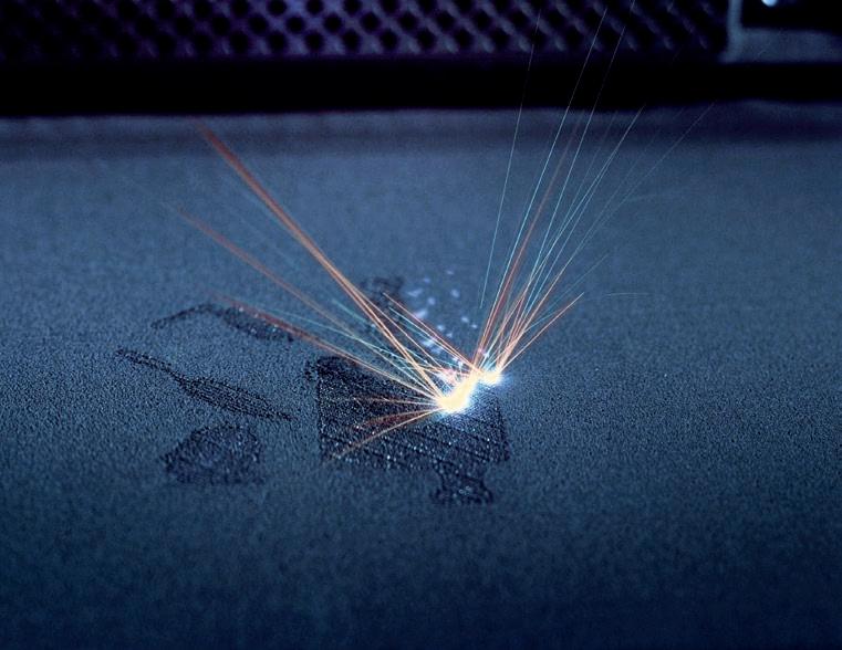
The metal AM build process. Direct metal laser sintering (DML) melts the powders into a 3D shape using very high-powered lasers
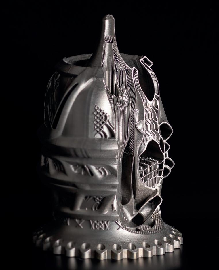
Hyperganic’s rocket engine design study. The possible applications of AM are almost unlimited and it’s already used in many sectors
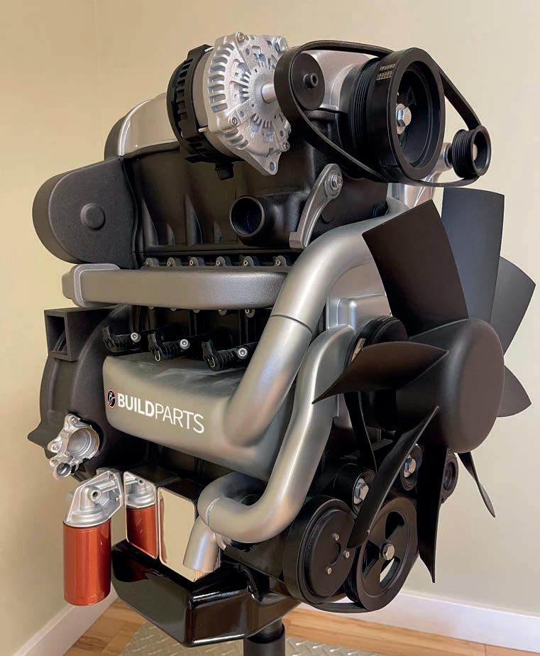
Build Parts by CIDEAS
CIDEAS used FDM, SLA and CLIP processes to create this highly detailed 100 per cent 3D printed trade show display engine model
SLA (stereolithography) was used to produce this HUD Navigation smart motorcycle helmet demonstrator. Accura 25 resin was chosen for its accuracy, durability and heat deflection. The process, which cures a resin with UV light, gives a good surface finish
Major machine manufacturers have demonstrated automated factory solutions that promise to dramatically improve productivity across the complete AM process chain, from CAD / CAM fi le preparation to part build, heat treatment and build plate removal. These systems remove some of the manual stages inherent in the AM production process and automate them into one system.
These AM production systems require the user to load the build plate, and then everything runs automatically until the part is complete. The systems are modular, so they can be built up to individual user requirements to complete a part from a CAD / CAM fi le upload to a serviceable component. They also often feature a control module for the fi lter system, cooling system, powder delivery pumps, lasers and other peripherals, as well as multiple build modules, a heat treatment module, post-processing module and an inspection module.
Two build chambers can even be used so two parts can be made simultaneously and, because the powder handling is integrated into each module, diff erent materials can be used in each build area.

Heat treatment
The heat treatment module in the system is critical as, when the build is complete, the heat treatment must be carefully controlled to ensure part quality is maintained. The AM process usually causes tension in a part and, if it is allowed to cool to room temperature before it is put through a heat treatment process, it can warp and be ruined.
Heat treatment does not occur in the build area. The modular system uses robotics to move the part to the heat treatment module.
After heat treatment, the component is transferred to a part removal module by robot, where it is turned upside down to remove any excess powder and then removed from its build plate by a roboticallycontrolled band saw. This must be done precisely to ensure the part is not damaged.
The part is then lowered into a bin with a foam inlay, turned upright, and then transferred into a fi nal machining area.
The user can automatically set the entire system to run each manufacturing and posttreatment process and then return to the machine later to retrieve a completed part, which makes it a very convenient and timeeffi cient manufacturing process.
The use of additive manufacturing in motorsport certainly shows no signs of abating, and it is likely that a much higher percentage of components on a racecar will soon be manufactured using this technology. We will undoubtedly also see the emergence of larger, faster and more precise machines, and a great many more materials from which components can be made. l