15 minute read
ELECTRIC MOTORS


Efficiency drive
With the growth in EV racing, the quest to improve efficiency in electric motors has gained pace in recent years, with new technologies and wonder materials emerging. Racecar assesses their impact
By Lawrence Butcher
Electric motorsport, probably more than any other genre of racing, is all about incremental gains, particularly in terms of powertrain development. Take Formula E, where, even in its first season of competition, the efficiency of the spec, McLaren-supplied motor and inverter package was around 96 per cent. A fair figure today would likely be somewhere between 98 and 99 per cent.
But however small the improvements, across the board – be it in WEC, F1 or FE – manufacturers have been chasing electrical efficiency gains from motors, inverters and battery systems. It is the first of these that we will focus on here.
An electric powertrain must be considered in terms of the motor and controller when thinking of efficiency (and, where used, the transmission). Each element is closely linked, and gains made in one area can easily be cancelled out if another part of the chain has excessive losses. Similarly, it is impossible to create a highly efficient motor without a suitably capable control system (just as an F1 engine would be useless without its ECUs).
To briefly recap the types of motor most found in racing applications, at one end of the scale are the very high output, but relatively crude, DC units, like those found in electric drag cars. These have excellent power characteristics but are hard to control and not suitable for applications that require energy recovery. Advanced hybrid and electric race vehicles tend to use AC (alternating current) motors and, amongst the various subsets of AC motors, synchronous motors are currently seen as the best solution. In most applications, this means the use of permanent magnet synchronous motors (PMSMs), of either the axial or radial flux type.
The majority of PMSMs utilise permanent magnets mounted on the surface of the rotor. This makes the motor appear magnetically ‘round’, and the motor torque is the result of the reactive force between the magnets on the rotor and the electromagnets of the stator. However, some PMSMs have magnets buried inside the rotor structure, referred to as Interior Permanent Magnet (IPM) motors.
Electrical losses
Common to ICE and electric machines are mechanical losses, though obviously they are far less significant in an electric motor. But whereas in an ICE there are losses in the combustion system, in a motor there are electrical losses to contend with.
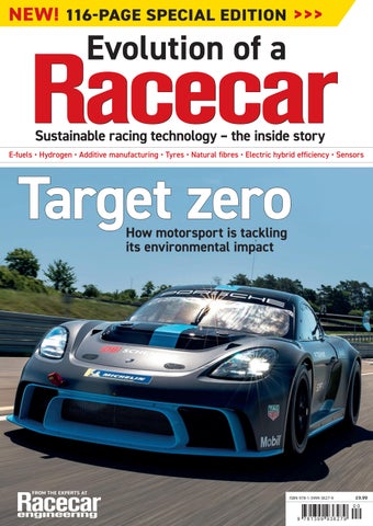
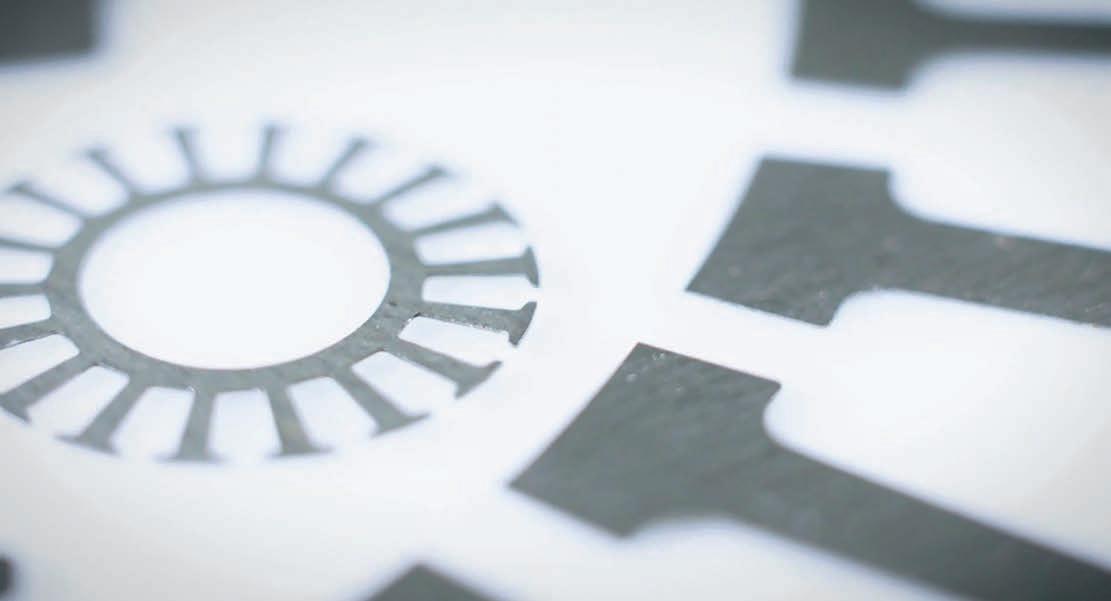
The arrangement of the copper windings is key to the performance of the electromagnet, as the pattern determines the direction of the electromagnetic field
Equipmake
»Each element of an electric powertrain is closely linked and gains made in one area can easily be cancelled out if another part of the chain has excessive losses
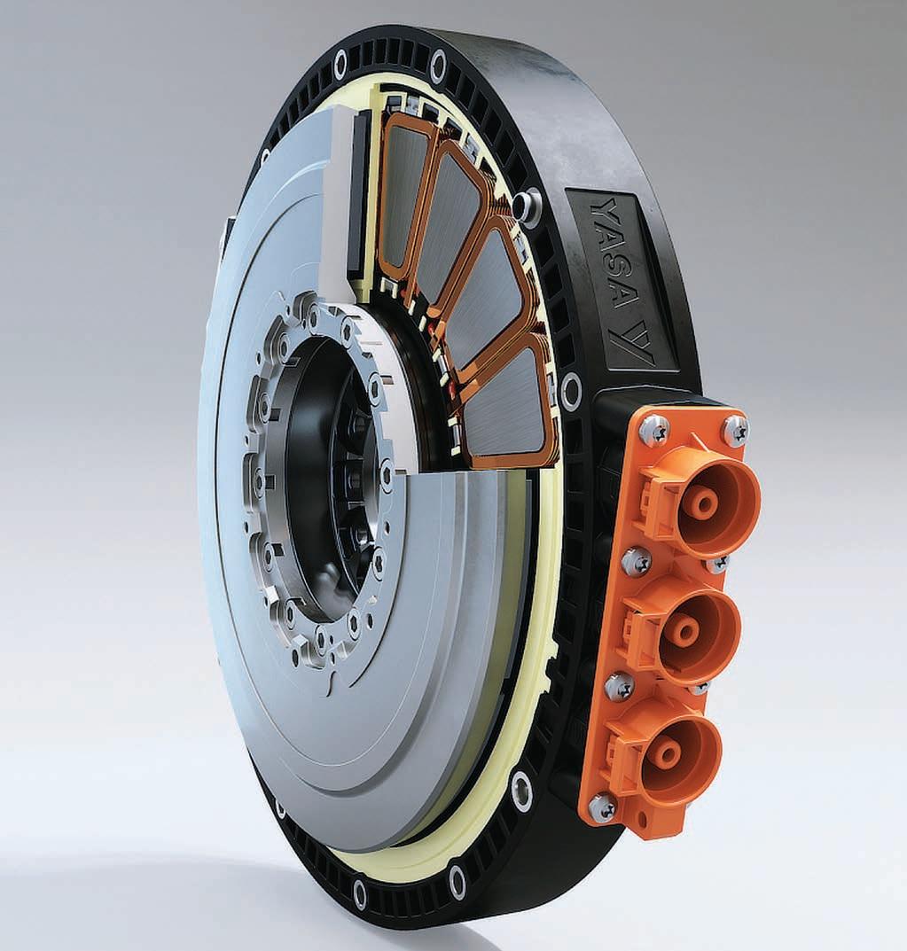
An axial flux e-motor with an integrated inverter unit. In this type of electric motor, the gap between the rotor and stator, or rather the flux between the two, is parallel to the axis of rotation
Furthermore, both ICE and electric motor losses tend to manifest themselves as heat, which must be managed, a subject which we will be returning to later.
Motor losses can be broken down into iron or core losses, and copper or ohmic losses, each with its own set of characteristics, both of which contribute to a reduction in efficiency. Typically, many of the phenomena that cause losses also increase in severity when one ups the power of a motor.
Iron losses
Starting with iron losses, normally shown as W/kg, these are comprised of eddy currents and hysteresis. Eddy currents, as their name suggests, are currents that swirl like eddies in a stream. They run perpendicular to the magnetic field of a stationary conductor (in this case the stator) and are induced by changing magnetic fields in a closed loop, according to Lenz’s law.
The problem is that as motor speed increases, so too do eddy current losses, which are proportional to the square of the electrical frequency of the motor. With the trend towards ever faster and more compact
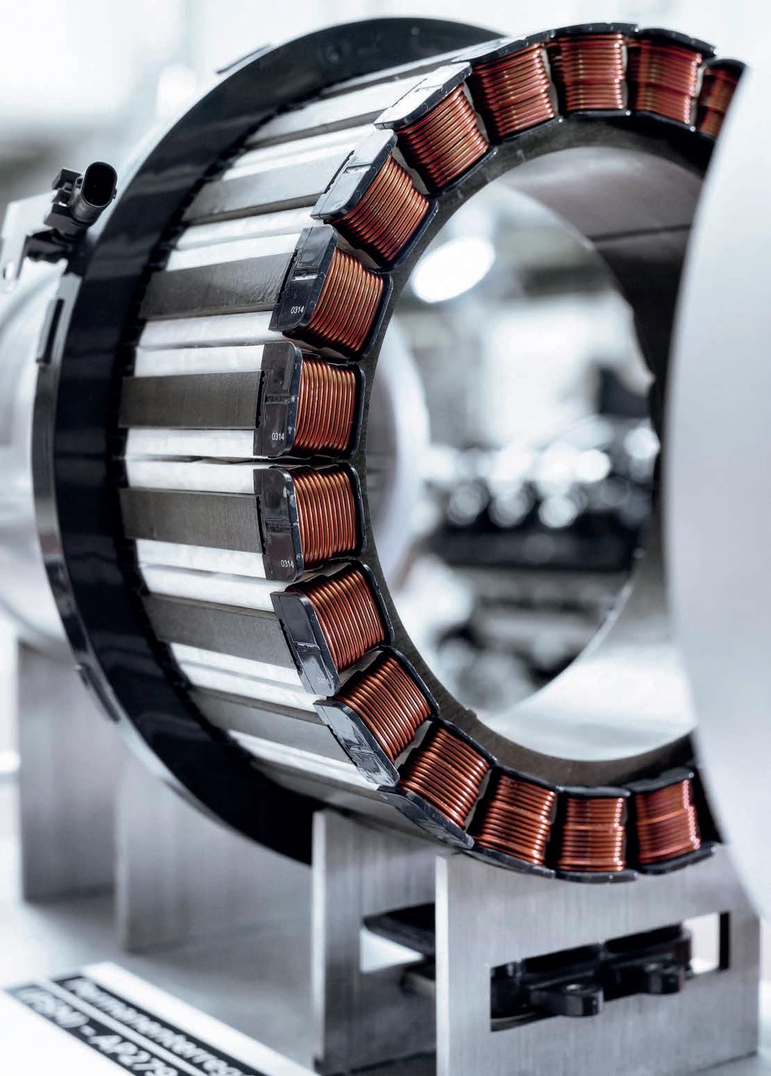
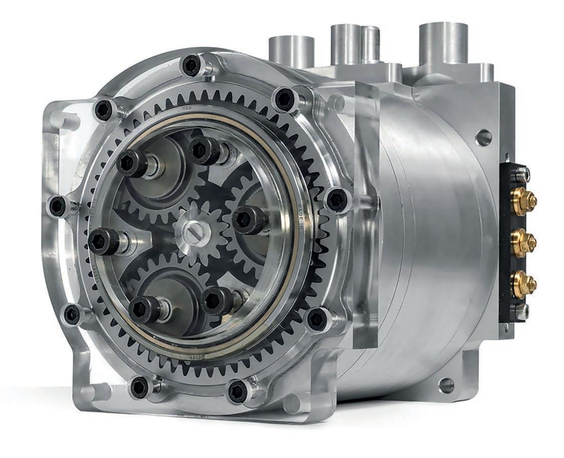
The permanent magnet radial flux motor is the choice for many motorsport applications. This APM 120R is an interior permanent magnet motor with samarium cobalt magnets
motors, iron losses are a major consideration for electric motor designers.
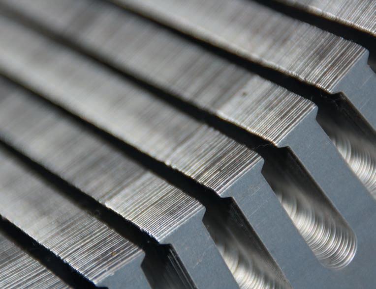
One of the main routes to reducing eddy current losses in the stator is through a combination of materials engineering and construction. Nearly every, but not all, contemporary high-performance motor features very thin steel laminations that form the stator stack, each separated by an insulation layer. Thin laminations create a smaller conduction path for the currents than if thicker laminations are employed.
With current being proportional to the area of the loop, reducing the area reduces the current that can flow. And as losses are proportional to the square of the current, even relatively small drops in current can net useful gains in efficiency.
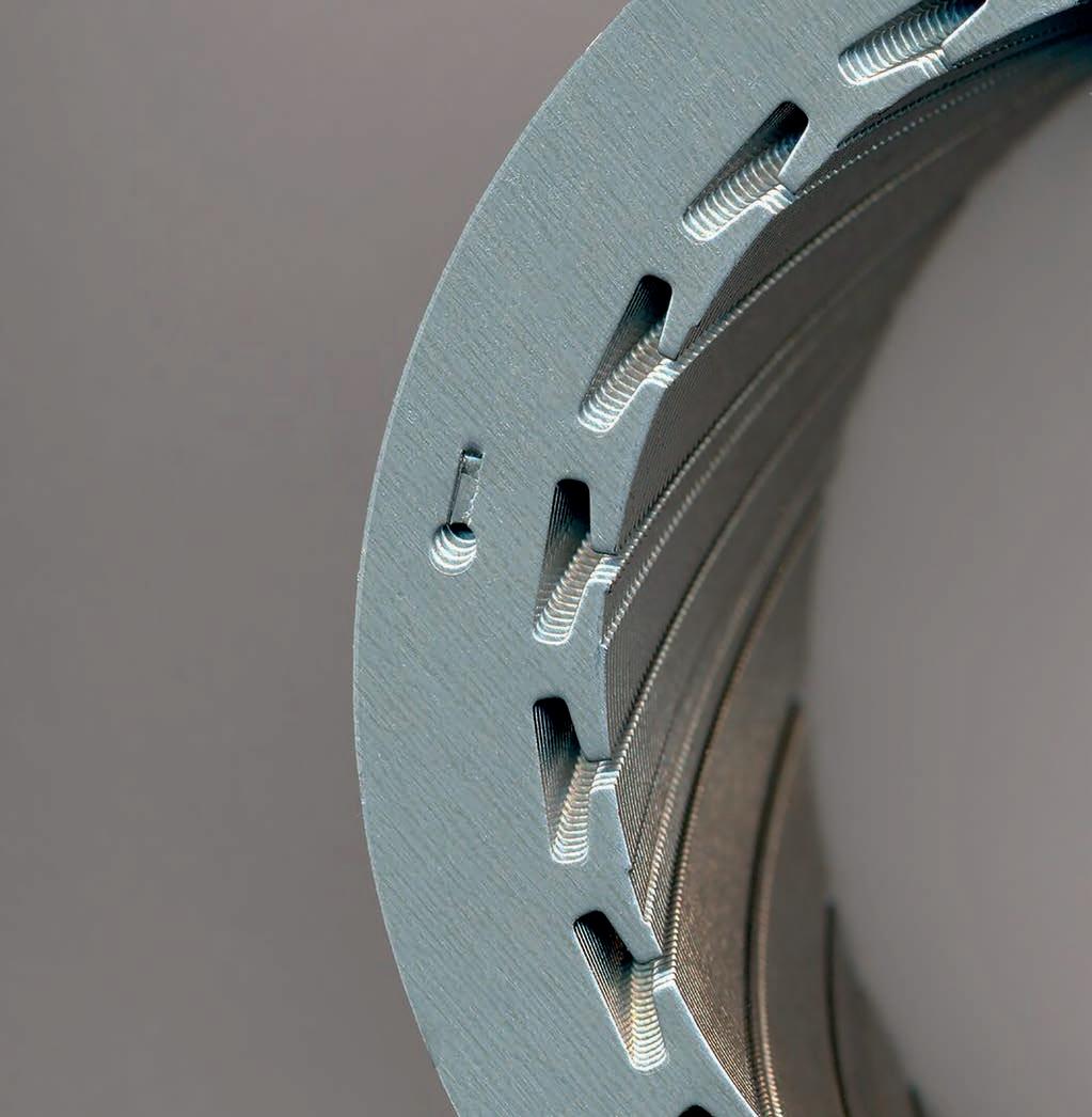
In the past, a thin lamination was considered to be in the region of 0.5mm, but advances in manufacturing techniques have seen much thinner laminations become available. For example, Arnold Magnetics produces its Arnon 5 and 7 laminations at 0.127mm and 0.178mm respectively. These are rolled from non-grain-orientated electrical steels (NGOES), which are ideal for motor use.
The company can also supply grainorientated electrical steels, more commonly used in transformers (which have different magnetic requirements) down to 0.025mm thickness. To put this into perspective, the Formula 1 regulations limit laminate to a minimum of 0.05mm in the MGU-K, though the MGU-H is not limited. According to Arnold Magnetics, a switch from a traditional 29 gauge (0.34mm) laminate to a 0.127mm production, can net in excess of a 60 per cent reduction in iron losses.
One issue with using exceptionally thin laminations is that the thinner the sheet, the harder it is to reliably stamp out the stator laminates. Factor in the ever-increasing complexity of stator design, coupled with the challenges of reliably joining – either mechanically or via bonding – the individual laminations together, and it is clear why the very thinnest materials are the preserve of high-value, low-volume motors where ultimate efficiency is required.
Another means of reducing eddy currents in the stator is to use high-resistivity steels, which will tend to be referred to as silicon or electrical steels and have low hysteresis. It used to be that these steels had the disadvantage of a low saturation flux density. In practice, this means a large and heavy stator was needed to achieve the same magnetic field as a material with a higher saturation flux density. But again, the past decade has seen new materials arrive on the market that have both high resistivity and good flux density.
Ultimate power density
Moving up another step, for ultimate power density, high-induction, low-loss cobalt alloys are favoured. For example, German firm, Vacuumschmelze, has long supplied its Vacoflux and Vacodur, 49 per cent cobalt-iron alloys into high-end racing. With exceptionally high saturation polarisation of 2.3T, they far outperform even the best silicon-steels, albeit at high cost.
To make such alloys more accessible, the company released its Vacoflux X1 in 2019, with a 17 per cent cobalt content. It claims that, compared to a motor using grade 20 NGOES, torque output can be increased by up to 12.5 per cent at a cost closer to electrical steel than the 49 per cent cobalt alloys.
Moving away from laminations, one of the latest developments in terms of stator materials are soft magnetic composites (SMCs), which have the potential to replace steel laminations in many motor applications. The great advantage of these is they have isotropic magnetic properties that allow for more complex magnetic design concepts than are possible with steel laminates, which have 2D magnetic properties.
SMCs are created using magnetic powder with an electrically resistive coating, which can be formed into complex 3D shapes using conventional powder metallurgy techniques. In addition to facilitating advanced magnetic designs, the insulating coating of the powder grains contains eddy currents within each grain of material, greatly reducing core losses at high frequencies (SMCs come into their own above 400Hz).
There are some challenges when it comes to processing these materials, though. For example, finished parts must be heat treated to remove micro stresses after the compaction process. However, because the insulation material degrades at a lower temperature than the base powder, iron, anneals at, it is hard to fully remove all stresses.
Hysteresis losses
All of the materials listed above also help reduce hysteresis losses. These are caused by the magnetisation and demagnetisation process within a motor core as current flow changes direction. As the magnetising force (current) increases, so too does the magnetic flux. However, as the magnetising force (current) decreases, the magnetic flux doesn’t decrease at the same rate, but less gradually. Therefore, when the magnetising force reaches zero, the flux density still has a positive value. In order for the flux density to reach zero, the magnetising force must be applied in the negative direction.
The relationship between the magnetising force and the flux density are represented on a hysteresis curve, or loop. The area of the hysteresis loop (rather like the area under the curve for an engine) shows the energy required to complete a full cycle of magnetising and de-magnetising. The greater the area of the loop, the higher the losses. So-called ‘soft’ magnetic materials, such as those detailed, are said to have a small area hysteresis loop.
It is worth noting that it is not only the magnetic material in the stator core that must be considered. The insulation between the individual laminations also needs to be kept to a minimum, while ensuring proper insulation is provided, and also allowing for thermal conductivity.
One favoured material for stator insulation is Nomex. While better known in racing for its use in fireproof equipment and honeycomb material for composites, Nomex paper is a widely used insulator. According to its manufacturer, DuPont, 80 per cent of BEVs utilise it in their traction motors, with the highest performance commercially available grade being Nomex 464 Lam, a lightweight, flexible paper insulation that can be supplied down to 0.05mm thickness.
DuPont is in fact a partner of the Alpine Renault F1 team, and Carlo Fiorella, the company’s global automotive manager, says that it uses Formula 1 as a test bed for its insulation materials, helping make them lighter, stronger and with better thermal conductivity. Taking this last factor, generally speaking, thermal conductivity and electrical insulation tend to work against each other. So how can these seemingly mutually exclusive properties be combined?
This edges toward the territory of confidential IP, but Fiorella was prepared to say: ‘We have materials that do enable high insulation with good thermal conductivity. Some of those are newer next-generation ones that are still in development, but it is a great area of research. We are always looking for ways to increase the thermal performance without decreasing safety.’
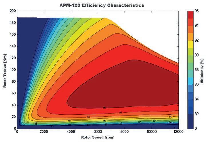
Efficiency map of an interior permanent magnet motor. With these, the magnets are positioned inside the rotor structure
Copper losses
Copper, or ohmic, losses occur predominantly within the stator windings of a PMSM, and can be broadly split into frequency dependent and frequency independent losses. These occur on the basis of I2R, where losses in Watts are equal to the current squared times the resistance of the wire. The key to lowering these is reducing the resistance in the winding wires.
Frequency-independent losses relate to the cross-sectional area, length and material of the stator windings, as well as their temperature. Pivotal to reducing the resistance of the windings for a given motor size (and increasing its torque density) is maximising the fill factor. This is the reason why most traction motors now rely on hairpin windings, where rectangular rather than round wire is used.
There are a host of other developments related to stator fill currently underway. For example, additive manufactured windings that can be created in forms impossible to achieve by regular winding processes.
Meanwhile, frequency-dependent losses revolve around a phenomenon called skin effect, whereby the effective diameter of a wire is reduced as the frequency of an alternating current increases. As the frequency goes up, the current flow moves to the surface of a wire, increasing the resistance
Carlo Fiorella, global automotive manager at DuPont
Changing the shape of the stator slots affects the magnetic path around them. This lamination steel is for the 200 to 2500Hz frequency range
and therefore temperature, which in turns increases resistance further.
The solution is to use smaller diameter wires, but this is only effective up to a point. The creation of eddy currents in wires adjacent to one another alters the distribution of current flowing through each wire, concentrating the current in areas of the conductor furthest away from adjacent wires with current flowing in the same direction. This is known as the proximity effect, and can have a significant impact on resistance. It is a careful balancing act to find the best ratio of conductor thickness and distribution.
In addition to good electrical design, effective cooling is vital to reducing copper losses in a motor. Most motors in a motorsport context will feature liquid cooling of one form or another, either direct cooling of the stator using dielectric fluid or, more commonly, the use of a cooling jacket around the stator, which interfaces using a cold plate.
Effective cooling
With the latter approach, one of the most important elements to consider is the interface between the stator and the cold plate. Maximising the thermal conductivity in this area is what produces efficient cooling. For example, if the contact between the windings and the plate is poor, or the cooling efficiency between the windings and the stator core is reduced, losses will increase. Therefore, elements such as the surface flatness of both the core and the cooling plates have a greater impact on cooling than the coolant flow within the cold plate.
The insulation material that encases the stator windings also plays an important role in cooling efficiency, with many motors using an insulating varnish. This has been an area of considerable development in recent years and single, double and triple-coated wires are available. Triple-coated wires are supposed to eliminate any pinholes in the insulation, which increases resistance to corona discharge (ionisation of air surrounding the wire). However, the thicker the coating, the lower the thermal conductivity, hence the development of varnishes that can be applied in a thin, pinhole-free coat and provide good corona resistance with high thermal conductivity.
Additionally, the thicker the insulation, the less space there is for wire, reducing fill factor, so the higher the resistance for a given current and the greater the temperate increase under load.
It’s worth noting that there are also some circumstances where absolutely maximising
YASA Motors
In YASA’s yokeless axial flux motor the flux jumps from the stator tooth to the magnets and back to the next stator tooth. Advantages of this design are the ability to have the flux interact with the two sets of magnets, significantly increasing the power density of the design – meaning less weight, less current, fewer losses and more power
fill factor may not be the route to optimum efficiency. For example, a particular stator design may be very good for cooling, but at the expense of copper fill, though the latter is cancelled out by the reduction in losses the additional cooling provides.
Complex matters
This article gives an introduction to some of the factors that drive motor efficiency, but there are a whole host of other mechanisms at work that create losses.
For example, PMSMs inherently suffer from a high level of ‘back’ EMF (electro motive force), a side effect of a magnet spinning within a stator. With a permanent magnet, the back EMF is proportional to motor speed so, once a motor reaches a certain speed, the back EMF will cancel out the available motor supply voltage, effectively limiting the maximum speed of a motor. This can be countered by ‘field weakening’ the motor, a process that injects extra currents into the winding, reducing the magnetic flux of the rotor magnets. Using this technique, motor speeds can be increased by a factor of five.
The use of different winding designs can also decrease back EMF, with distributed (where the windings are distributed across the air gap of the motor) generally proving more efficient than concentrated windings (where each winding only goes around a single slot in the motor). As always, there is a ‘however’, and in this case it is that well designed concentrated windings can also have low back EMF.
Then there are losses related to the rotor’s magnetic design, and even the sleeve used to constrain the magnets on an PMSM. For example, if the sleeve is conductive, this creates a distortion in the magnetic flux and causes eddy currents. The use of a nonconductive sleeve removes these losses, but there is a caveat here too, of course. If, for example, an Inconel sleeve is used, overall rotor losses can actually be lower due to it shielding the rotor. To achieve a similar level of performance with a non-conductive sleeve requires the use of laminated magnets, which have lower losses at the cost of a small amount of torque output.
Summing up, then, it would be fair to say that the exceptional performance and efficiency of current machines is down to a complex combination of innovative thinking, materials development and advances in modelling capabilities. l

Experience the advantage of outstanding performance.
The engineers of the world’s best performing electric motors have evolved. Helix now makes ultimate power density accessible through scalable core technology and volume production facilities. On the road and track, at sea, in the air and in a multitude of industrial applications, Helix electric power is the future.